
1st edition English September 2012
DOWNLOAD MANUAL
INTRODUCTION
Power Shuttle transmission
Power Shuttle transmission external controls
Power
Powered front axle
Front bevel gear set and dif ferential
Final drive steering and shafts front axle
Rear axle system
Powered rear axle
Rear bevel gear set and dif ferential
Planetary and final drives
Brakes and controls
Parking brake / Parking lock
Hydraulic service brakes
Pump control valves
Fixed displacement pump
hitch control valve
hitch cylinder
Remote control valves
Reservoir , cooler , and filters
Safety and main relief valves
Front loader bucket hydraulic system
T ool quick coupler hydraulic system
Rear hitch external controls
Frames and ballasting
Frame
Ballasts and supports
Steering
Steering control
Hydraulic control components
Cylinders
Wheels
Front wheels 1
Rear wheels
Cab climate control
Air conditioning
Electrical systems
Cab/Platform harnesses and connectors
Cab engine controls
F AUL T CODES
Front loader and bucket
Arm Bucket cab, and decals
Machine shields and guards
Protections - ROPS and FOPS
Cab


Safety rules DANGER
Improper operation service this machine can result accident. not operate this machine perform any lubrication, maintenance, repair until you have read and understood the operation, lubrication, maintenance, and repair information. Failure comply will result death serious injury
D0010A
W ARNING
Maintenance hazard!
Always perform all service procedures punctually the intervals stated this This ensures optimum performance levels and maximum safety during machine operation.
Failure comply could result death serious injury .
W ARNING
Pressurized system!
W0132A
Before attempting any service procedure, your responsibility know the number accumulators the and the correct procedure for releasing the pressure each accumulator
Failure comply could result death serious injury .
NOTICE: Extreme working and environmental conditions require shortened service
W0136A
Use Case fluids, lubricants, and filters for the best protection and performance your machine. All fluids, lubricants, and filters must disposed compliance with environmental standards and Contact your dealer with any questions regarding the service and maintenance this
Read the safety decals and information decals the Read the Operator ’ s Manual and safety Understand the operation the machine before you start any
Before you service the put a Not tag the steering wheel over the key Ensure the tag a location where everyone who might operate service the machine may see clearly One tag included with your new machine. Additional tags are available from your dealer .
Plastic and resin parts
• A void using gasoline, paint thinner , etc. when cleaning plastic parts, console, instrument cluster , etc.
• Use only water , mild and a soft cloth when you clean these
• Using gasoline, thinners, etc. can cause discoloration, cracking, deformation the part being cleaned.
Safety rules Ductile iron
DANGER
Improper operation service this machine can result accident. Any unauthorized modifications made this machine can have serious consequences. Consult authorized dealer modifications that may required for this not make any unauthorized modifications. Failure comply will result death serious injury .
Before you drill holes any part this make sure the part not cast ductile See your dealer you not know a part cast ductile The following are cast ductile iron parts:
• two wheel drive steering link
• dump links
• front axle
• Air Conditioning / compressor mounting bracket
Unauthorized modifications cast ductile iron parts can cause injury W drilling can cause cast ductile iron break. not weld, cut, drill repair attach items cast ductile iron parts this machine.
Safety rules
Before welding the machine you must the following. you have any questions about welding the machine contact your dealer
• Disconnect the
• Disconnect the alternator terminal
• Disconnect the instrument cluster
• Disconnect the engine control Disconnect all connectors from the engine harness the
• Disconnect the controller for the loader 4 1 bucket auxiliary hydraulics, equipped (one connector , located under the loader valve the rear , left derside the
DOWNLOAD MANUAL
Safety rules
Unless otherwise instructed, always perform these steps before you service the machine: Park the machine a level
Place the loader bucket the ground, with the bottom the loader bucket parallel the surface.
Place the direction control lever and the transmission you need open the hood perform raise the loader arms and install the support Shut down the
Place a Not tag the key switch that visible other workers remove the key
SER VICE MANUAL
570NXT
Engine - General specification
Engine - Speeds stall test check sheet

RAIL12UTL0338GA 1
Engine - Prepare for stall tests
Perform the stall test find the cause poor
The main relief valve must set within specifications achieve accurate readings when performing the following stall
The engine run full throttle and the transmission and hydraulic systems are engaged separately , and then gether .
Comparing the engine speeds from the stall test with the check sheets this section will help find the cause the problem. can necessary check a separate system find the exact cause the problem.
Use a photo tachometer other tachometer equal accuracy get accurate results from the stall
The transmission and hydraulic system must operating temperature before doing the stall Heat the oil according instructions this
Machines with standard transmission
NOTE: Check the throttle linkage
Apply the parking
Move the transmission gear selector into fourth gear
Lock the brake pedals together Put your foot the service brakes and hold the machine with service
Release the parking
With the engine running low move the tion control lever
Slowly increase the engine speed full the machine begins move any decrease the engine speed low idle and stop the
Procedure heat torque converter and hydraulic oil
Apply the parking
Start and run the engine low
Run the engine full hold the loader control lever the rollback position for
Return the loader control lever neutral for
Repeat steps 3 and 4 until the temperature the oil ( 126 ) The side the reservoir will very warm this
With the engine running low move the mission control fourth gear and the direction trol lever
Run the engine full throttle for seconds.
Decrease the engine speed low idle and move the direction control lever neutral for
Repeat steps 6 through 8 until the pointer the gauge for transmission oil temperature the ter the green zone the gauge for transmission oil
Stall test procedure
Prepare the machine for the stall test according instructions this
Heat the oil according instructions this
Apply the parking brake and start the
With the engine running full hold the loader control lever the lift position and read the ter Record the reading line 1 the check
Decrease the engine speed low
Move the transmission control lever fourth gear
Lock the brake pedals together Put your foot the service brakes and hold the machine with service
Release the parking
Move the direction control lever
Slowly increase the engine speed full throttle and read the tachometer Record the reading line 3 the check sheet.
1 With the transmission control lever fourth gear , the direction control lever forward, and the engine ning full hold the loader control lever the lift position and read the tachometer Record the reading line 4 the check
Decrease the engine speed low move the directional control lever
Run the engine low idle for two minutes and then stop the
See the check sheet understand the results the stall test.
Engine - Remove
Prior operation:
Drain the hydraulic
Prior operation:
Disconnect the
Prior operation: Remove the engine
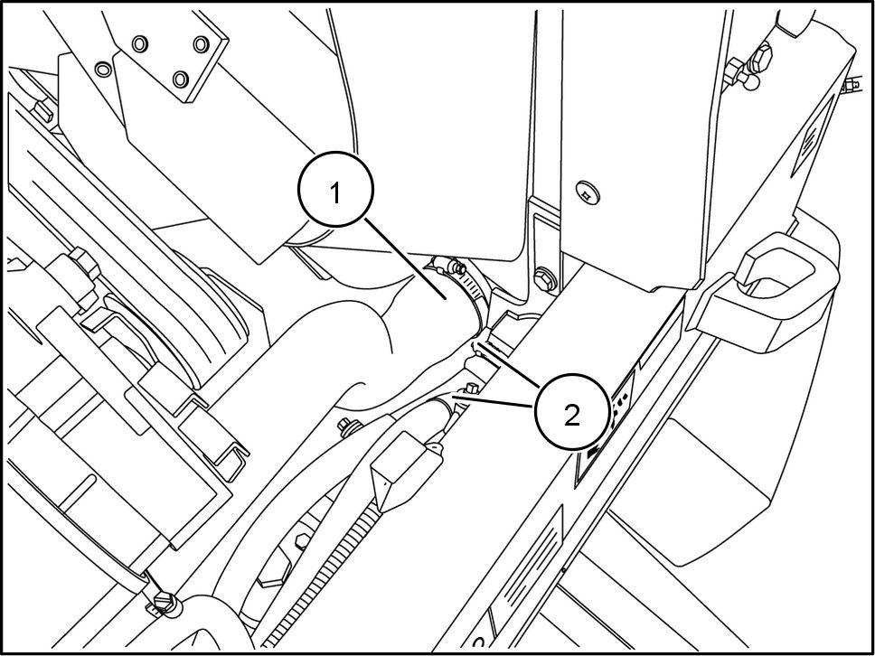
Remove the air intake tube support bracket bolts (1) and bracket (2)

Disconnect the A / C condenser inlet line (1) .
Disconnect the inlet fuel cooler line (2)
Disconnect the outlet fuel cooler line (3)
Disconnect the A / C condenser outlet line (4)

Remove the horn bracket nut (1) Place the horn and horn bracket away from the cooling

RAPH1
Loosen and remove the receiver / dryer hold - down clamps (1) Place the receiver / dryer away from the cooling package.

Support the cooling package housing wrapper

Remove the cooling package housing wrapper bolts (1) , (2)

RAPH1 1TLB0036BA 4
RAPH1 1TLB0038BA 5
RAPH1 1TLB0029BA 6
10. Carefully lift and remove the cooling package ing wrapper
1 Label and disconnect the hydraulic oil hoses (1) ing the hydraulic oil cooler

Disconnect the air intake tube (1) from the air cleaner

RAPH1 1TLB0038BA 7
RAPH1 1TLB0034BA 8
RAPH1 1TLB0031BA 9
13. Disconnect the lower radiator hose (1) from the ator
Label and disconnect the transmission oil cooler hoses (2) leading the transmission oil cooler .
Disconnect the turbo outlet tube (1) the
16. Disconnect the upper radiator hose (2) from the diator

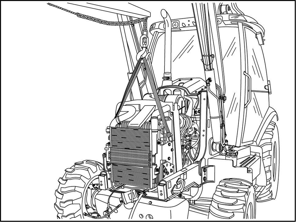
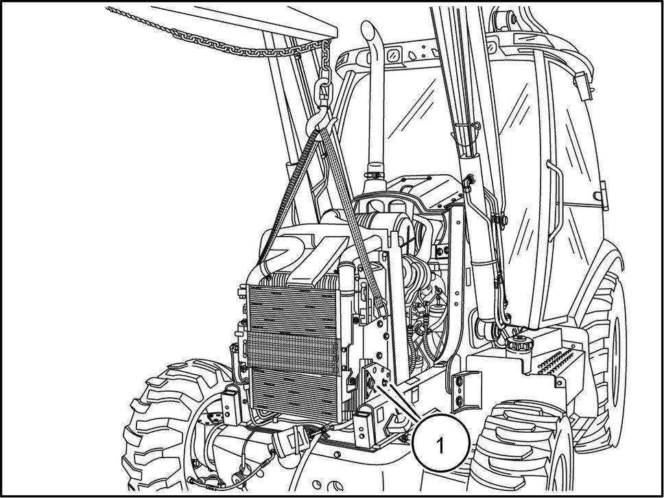
Support the cooling package using lifting
RAPH1 1TLB0033BA
RAPH1
RAPH1
18. Remove the hood strut post (2) and retainer (1) .
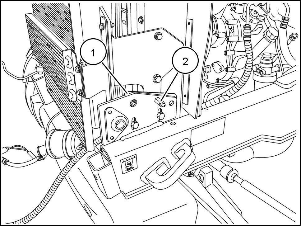
Remove the cooling package retaining bolts (1)
Carefully lift and remove the cooling
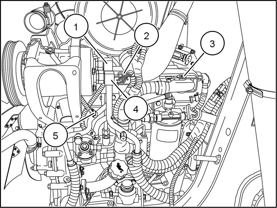
Disconnect the A / C high pressure line (1)
Disconnect electrical connectors (2) and (3)
22. Disconnect the A / C low pressure line (4) .
23. Disconnect the A / C condenser voltage wire (5) .
RAPH1 1TLB0028BA
RAPH1 1TLB0027BA
RAPH1 1TLB0045BA
24. Disconnect fuel lines (1) and (2) .

Disconnect the water sensor electrical connector (not
NOTE: W ater sensor located the bottom the primary fuel filter
Remove the diesel particulate filter (DPF)
See Particulate filters - Remove (10.501)
Remove the DPF tray (1)

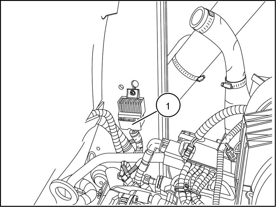
Disconnect the glow plug control unit electrical nector (1) .
RAPH1 1TLB0041BA
RAPH1 1TLB0022BA
RAPH1 1TLB0021BA
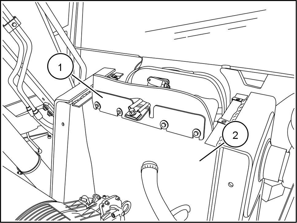
29. Remove the supporting bracket (1) and hanging rier curtain (2)
Disconnect the heater hose (1)
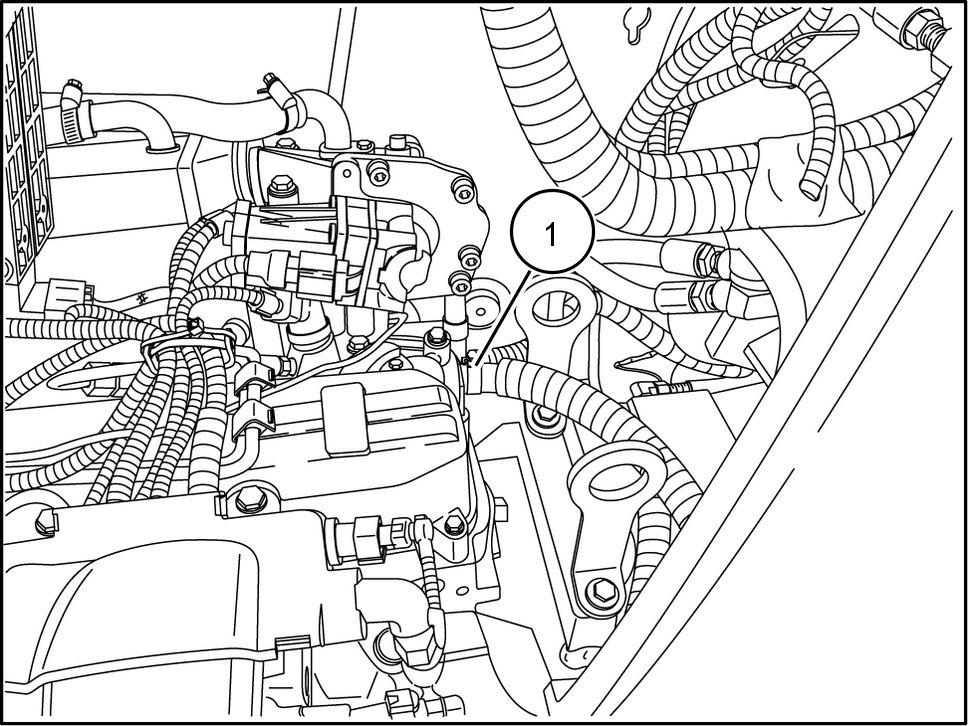
Label and disconnect the air sensor wires (1)

RAPH1 1TLB0040BA
RAPH1 1TLB0039BA
RAPH1 1TLB0044BA
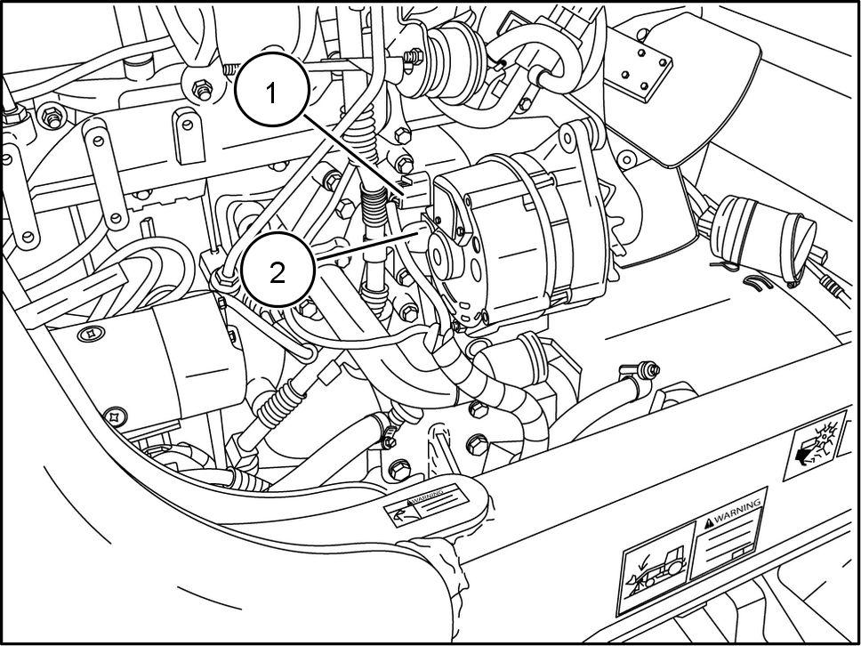
Label and disconnect the alternator electrical nector (1) and the alternator battery wire (2)
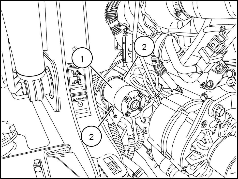
Remove the starter (1)
Remove the button plug and the insert flywheel ing part number 380000988


RAPH1 1TLB0043BA
RAPH1 1TLB0042BA
RAPH1 1TLB0017BA
35. Remove the cover . T urn the flywheel using the wheel turning tool expose the flywheel bolts (1)
Remove the flywheel bolts (1)

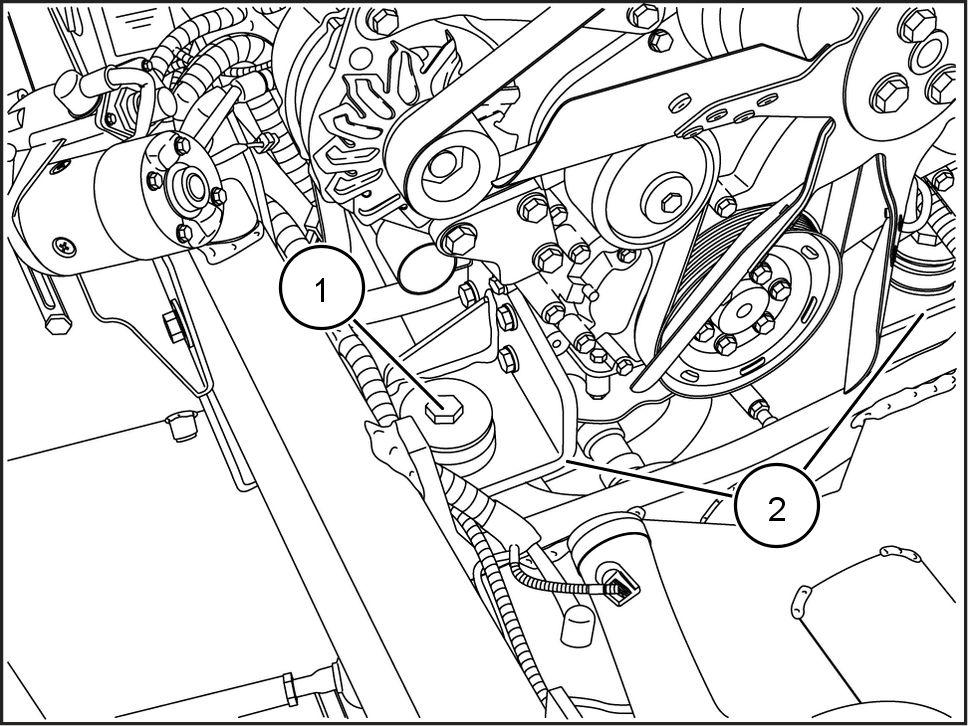
Support the engine using lifting

Removing the engine mounts (1)
NOTE: Lower radiator hose removed for picture clarity

RAPH1 1TLB0016BA
RAPH1 1TLB0018BA
RAPH1 1TLB0019BA
38. Remove the bell housing bolts (1) .

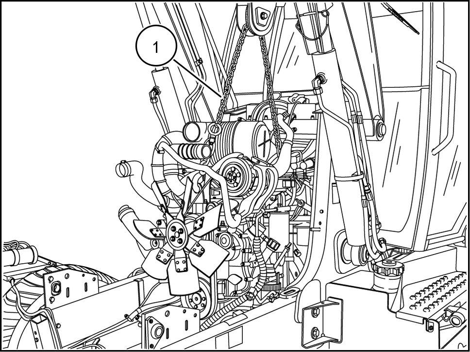
Carefully lift and remove the engine from the
RAPH1 1TLB0020BA
RAPH1 1TLB0018BA
Engine - Install
Carefully lower the engine into the
1
Install the bell housing bolts (1) T ighten the bell housing bolts (1) a torque - ()
Install the engine mounts (2) T ighten the mounting bolts (1) 212 - 241 N·m ( 156 - 178 )
NOTE: Lower radiator hose removed for picture clarity
RAPH1 1TLB0018BA
RAPH1
RAPH1
Remove the lifting equipment (1) .
Install the flywheel bolts (1) . T ighten the flywheel bolts N·m ( )
Install the bell housing flywheel bolt cover and button
Install the starter (1) T ighten starter bolts (2) a torque N·m ( )
RAPH1 1TLB0018BA 4
RAPH1
RAPH1
Connect the alternator electrical connector (1) and the alternator battery wire (2)
Connect the air sensor wires (1)
Connect the heater hose (1)
RAPH1 1TLB0043BA 7
RAPH1
RAPH1