
INTRODUCTION
DISTRIBUTIONSYSTEMSA
TRAVELLINGD
BODYANDSTRUCTURE E
INTRODUCTION
DISTRIBUTIONSYSTEMSA
TRAVELLINGD
BODYANDSTRUCTURE E
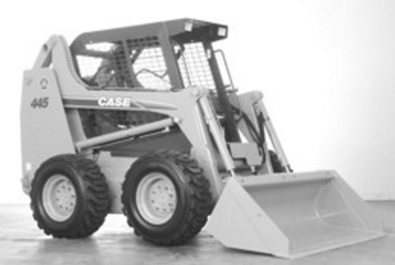
435,445,445CT
Thismanualhasbeenproducedbyanewtechnicalinformationsystem.Thisnewsystemisdesignedtodeliver technicalinformationelectronicallythroughCDROMandinpapermanuals.AcodingsystemcalledICEhasbeen developedtolinkthetechnicalinformationtootherProductSupportfunctionse.g.Warranty.
Technicalinformationiswrittentosupportthemaintenanceandserviceofthefunctionsorsystemsonacustomers machine.Whenacustomerhasaconcernonhismachineitisusuallybecauseafunctionorsystemonhismachine isnotworkingatall,isnotworkingefficiently,orisnotrespondingcorrectlytohiscommands.Whenyourefertothe technicalinformationinthismanualtoresolvethatcustomersconcern,youwill findalltheinformationclassified usingthenewICEcoding,accordingtothefunctionsorsystemsonthatmachine.Onceyouhavelocatedthe technicalinformationforthatfunctionorsystemthenyouwill findallthemechanical,electricalorhydraulicdevices, components,assembliesandsub-assembliesforthatfunctionorsystem.Youwillalso findallthetypesofinformation thathavebeenwrittenforthatfunctionorsystem,thetechnicaldata(specifications),thefunctionaldata(howit works),thediagnosticdata(faultcodesandtroubleshooting)andtheservicedata(remove,installadjust,etc.).
ByintegratingthisnewICEcodingintotechnicalinformation,youwillbeabletosearchandretrievejusttheright pieceoftechnicalinformationyouneedtoresolvethatcustomersconcernonhismachine.Thisismadepossibleby attaching3categoriestoeachpieceoftechnicalinformationduringtheauthoringprocess.
The firstcategoryistheLocation,thesecondcategoryistheInformationTypeandthethirdcategoryistheProduct:
• LOCATION-isthecomponentorfunctiononthemachine,thatthepieceoftechnicalinformationisgoingto describee.g.Fueltank.
• INFORMATIONTYPE-isthepieceoftechnicalinformationthathasbeenwrittenforaparticularcomponentor functiononthemachinee.g.CapacitywouldbeatypeofTechnicalDatathatwoulddescribetheamount offuelheldbytheFueltank.
• PRODUCT-isthemodelthatthepieceoftechnicalinformationiswrittenfor.
Everypieceoftechnicalinformationwillhavethose3categoriesattachedtoit.Youwillbeabletouseany combinationofthosecategoriesto findtherightpieceoftechnicalinformationyouneedtoresolvethatcustomers concernonhismachine.
Thatinformationcouldbe:
• thedescriptionofhowtoremovethecylinderhead
• atableofspecificationsforahydraulicpump
• afaultcode
• atroubleshootingtable
• aspecialtool
HowtoUsethisManual
ThismanualisdividedintoSections.EachSectionisthendividedintoChapters.Contentspagesareincludedat thebeginningofthemanual,theninsideeverySectionandinsideeveryChapter.AnalphabeticalIndexisincluded attheendofaChapter.Pagenumberreferencesareincludedforeverypieceoftechnicalinformationlistedin theChapterContentsorChapterIndex.
EachChapterisdividedintofourInformationtypes:
• TechnicalData(specifications)forallthemechanical,electricalorhydraulicdevices,componentsand, assemblies.
• FunctionalData(howitworks)forallthemechanical,electricalorhydraulicdevices,componentsand assemblies.
• DiagnosticData(faultcodes,electricalandhydraulictroubleshooting)forallthemechanical,electricalor hydraulicdevices,componentsandassemblies.
• Servicedata(removedisassembly,assemble,install)forallthemechanical,electricalorhydraulicdevices, componentsandassemblies.
Sections
Sectionsaregroupedaccordingtothemainfunctionsorasystemsonthemachine.EachSectionisidentifiedby aletterA,B,Cetc.TheamountofSectionsincludedinthemanualwilldependonthetypeandfunctionofthe machinethatthemanualiswrittenfor.EachSectionhasaContentspagelistedinalphabetic/numericorder.This tableillustrateswhichSectionscouldbeincludedinamanualforaparticularproduct.
SECTION
A-DistributionSystems
B-PowerProduction
C-PowerTrain
D-Travelling
E-BodyandStructure
F-FramePositioning
G-ToolPositioning
H-WorkingArm
J-ToolsandCouplers
K-CropProcessing
L-FieldProcessing
PRODUCT
TractorsXXXXXXXX
Vehicleswithworkingarms:backhoes, excavators,skidsteers,..... XXXXXXXXX
Combines,forageharvesters,balers,.... XXXXXXXXXX
Seeding,planting, floating,spraying equipment,.... XXXXXXXXX
Mountedequipmentandtools,.....XXXX
Chapters
EachChapterisidentifiedbyaletterandnumbercombinatione.g.EngineB.10.AThe firstletterisidenticaltothe Sectionletteri.e.ChapterB.10isinsideSectionB,PowerProduction.
CONTENTS
TheChapterContentslistsallthetechnicaldata(specifications),functionaldata(howitworks),servicedata (remove,installadjust,etc..)anddiagnosticdata(faultcodesandtroubleshooting)thathavebeenwritteninthat Chapterforthatfunctionorsystemonthemachine. Contents
TheChapterIndexlistsinalphabeticalorderallthetypesofinformation(calledInformationUnits)thathavebeen writteninthatChapterforthatfunctionorsystemonthemachine.
InformationUnitsandInformationSearch
Eachchapteriscomposedofinformationunits.EachinformationunithastheICEcodeshowninparentheseswhich indicatesthefunctionandthetypeofinformationwritteninthatinformationunit.Eachinformationunithasapage referencewithinthatChapter.Theinformationunitsprovideaquickandeasywayto findjusttherightpieceof technicalinformationyouarelookingfor.
exampleinformationunitStackvalve-SectionalView(A.10.A.18-C.10.A.30) InformationUnitICEcode
ICEcodeclassification

Navigatetothecorrectinformationunityouaresearchingforbyidentifyingthefunctionandinformationtype fromtheICEcode.
• (1) Functionand (2) Informationtype.
• (A) correspondstothesectionsoftherepairmanual. (B) correspondstothechaptersoftherepairmanual. (C) correspondstothetypeofinformationlistedinthechaptercontents,Technicaldata,FunctionalData, DiagnosticorService. (A) and (B) arealsoshowninthepagenumberingonthepagefooter. THERESTOFTHECODINGISNOTLISTEDINALPHA-NUMERICORDERINTHISMANUAL.
• Youwill findatableofcontentsatthebeginningandendofeachsectionandchapter. Youwill findanalphabeticalindexattheendofeachchapter.
• Byreferringto (A), (B) and (C) ofthecoding,youcanfollowthecontentsorindex(pagenumbers)andquickly findtheinformationyouarelookingfor.
Thepageheaderwillcontainthefollowingreferences:
• SectionandChapterdescription
Thepagefooterwillcontainthefollowingreferences:
• PublicationnumberforthatManual,SectionorChapter.
• Versionreferenceforthatpublication.
• Publicationdate
• Section,chapterandpagereferencee.g.A.10.A/9
435,445,445CT

WARNING

CSM118-Twopersonsarerequiredtoperformthe flowmetertestsforsafetytoavoidpossibleinjury.One personmustbeseatedintheoperatorsseatwiththeSeatBardownwhentheengineisrunning.The secondpersonistocontrolthe flowmeterandtakethereadings.
1.Parkthemachineonalevelsurface.Lowerthe loaderbuckettothe floor.Stoptheengine.
2.Disconnectthehosefromthepumppressureport atTestPoint1.Installapluginthehose.Connect the flowmeter inlethosetothe fittingatthepressure portofthepump.
3.Putthe flowmeteroutlethoseintothehydraulic reservoir.Usewiretofastenthe flowmeteroutlet hosebelowthesurfaceofthehydraulicoil.
4.Makesurethattheoillevelinthehydraulicreservoir iscorrect.
5.Makesurethatthepressurevalveofthe flowmeter isopenedcompletely.
6.Theoilmustbeatoperatingtemperature.Ifthe oilisnotatoperatingtemperature,runtheengine atfullthrottleandclosethepressurevalveofthe flowmeteruntilthepressuregaugeindicates103bar (1500psi).Continuetoruntheengineatfullthrottle untilthetemperatureoftheoilis52°C(125°F).Then openthepressurevalvecompletely.
7.Makesurethatthepressurevalveisopened completely.Adjusttheenginespeedto2300r/min (rpm)andreadthe flowgauge.Readthe flowand recordthereadingastestnumber1.
8.Slowlyclosethepressurevalveonthe flowmeter untilthepressuregaugeindicates97bar(1400psi). Keeptheenginerunningat2300r/min(rpm).Read the flowandrecordthereadingastestnumber2.
9.Slowlyclosethepressurevalveonthe flowmeter untilthepressuregaugeindicates124bar(1800 psi).Keeptheenginerunningat2300r/min(rpm). Readthe flowandrecordthereadingastest number3.
10.Slowlyclosethepressurevalveonthe flowmeter untilthepressuregaugeindicates152bar(2000 psi).Keeptheenginerunningat2300r/min(rpm). Readthe flowandrecordthereadingastest number4.
11.Openthepressurevalvecompletely.Decreasethe enginespeedtolowidleandstoptheengine.
NOTE: Understandingtheresultsofthetestsareoutlined inthestepsbelow.
12.Iftheoutputatminimumpressurewaslessthan thespecificationforGearPumpFlowtoLoader (MachineinNeutral)referto HydraulicpumpGeneralspecification(A.10.A.20-D.40.A.10),the problemcanbearestrictionbetweenthereservoir andthegearpump,ortheproblemcanbeabadly wornordamagedgearpump.
13.Iftheoutputatminimumpressurewasmorethan thespecificationreferto Hydraulicpump-General specification(A.10.A.20-D.40.A.10),thereareno problemsbetweenthereservoirandthegearpump. However,thegearpumpcanbewornordamaged andstillhavegood flowatminimumpressure.
14.Lossofoutputat152bar(2200psi)indicatesthat thegearpumpiswornordamaged.Todetermine theefficiencyofthegearpump,dividethe flow indicationfromtestnumber4bythe flowindication fromtestnumber1.Thisanswermultipliedby100 isthepercentefficiencyofthegearpump.Ifthe efficiencyofthegearpumpislessthan75%,repair orreplacethegearpump.Iftheefficiencyofthe gearpumpismorethan75%,thepumpisgood.
DISTRIBUTIONSYSTEMS-PRIMARYHYDRAULICPOWERSYSTEM
Hydraulicpump-Remove(A.10.A.20-F.10.A.10) 435,445,445CT
1.Loosenandremovethemountingboltsandwashers forthe floorplateandthecover.Removethe floor plateandthecovertogainaccesstothehydraulic pump.

2.Placeashoptowelunderthegearpump.
3.Removethecapfromthehydraulicreservoir. CAS1871
4.Connectavacuumpumptothehydraulicreservoir. CAS10192
5. Reservoir-Applyvacuum(A.10.A.22-F.35.A.50) Startthevacuumpump.
6.Taganddisconnectthehosefromthe fittingatthe suctionportofthegearpump.
7.Installapluginthehoseandacaponthe fitting.
8.Taganddisconnectthehosefromthe fittingatthe pressureportofthegearpump.
9.Installapluginthehoseandacaponthe fitting. 10.Stopthevacuumpump.
104/05/2005 A.10.A/32
DISTRIBUTIONSYSTEMS-PRIMARYHYDRAULICPOWERSYSTEM
11.Loosenandremovethepumpmountingboltsand washers.
12.Removethegearpumpfromthehydrostaticpump mountinglocation.
DISTRIBUTIONSYSTEMS-PRIMARYHYDRAULICPOWERSYSTEM
Hydraulicpump-Disassemble(A.10.A.20-F.10.A.25) 435,445,445CT
1.Drawalignmentmarksonthehousingwithawhite marker.Thesemarkswillbereferencedduring assembly.

2.Loosenandremovethesocketboltsandwashers.

3.Removethecover.

DISTRIBUTIONSYSTEMS-PRIMARYHYDRAULICPOWERSYSTEM
4.Removethegearplate.
5.Removethedowelpins.
6.Rotatethegearteethuntilonegeartoothis centered insidetwogearteeth.Drawamarkwitha whitemarker.Thismarkwillbereferencedduring assembly.


DISTRIBUTIONSYSTEMS-PRIMARYHYDRAULICPOWERSYSTEM
7.Removethedriveshaft.
8.Removetheidlershaft.
9.Removethewearplatefromthecover.


DISTRIBUTIONSYSTEMS-PRIMARYHYDRAULICPOWERSYSTEM
10.Removethewearplatefromthebody.

11.Removeanddiscardthesealringfromthecover.

12.Removeanddiscardthesealringfromthebody.

DISTRIBUTIONSYSTEMS-PRIMARYHYDRAULICPOWERSYSTEM
13.Removeanddiscardthetopsealfromthebody.

14.Removeanddiscardthebottomsealfromthebody.

DISTRIBUTIONSYSTEMS-PRIMARYHYDRAULICPOWERSYSTEM
Hydraulicpump-Visualinspection(A.10.A.20-F.40.A.10) 435,445,445CT
1.Inspectthebrasssurfacesofthewearplates.

2.Inspectthedriveandidlershaftsfordamage.

3.Inspectthebearingsleevesofthedriveandidler shaftsinthebodyandcover.

DISTRIBUTIONSYSTEMS-PRIMARYHYDRAULICPOWERSYSTEM
4.Inspectthebodyandcoversurfaces.

DISTRIBUTIONSYSTEMS-PRIMARYHYDRAULICPOWERSYSTEM
Hydraulicpump-Assemble(A.10.A.20-F.10.A.20) 435,445,445CT
1.Lubricateandinsertthebottomsealintothegroove ofthebody.
2.Lubricateandinsertthetopsealintothegrooveof thebody.
NOTE: Thetopsealwillbeplacedontopofthebottom seal.
3.Lubricateandinsertanewsealringintothegroove ofthebody.
DISTRIBUTIONSYSTEMS-PRIMARYHYDRAULICPOWERSYSTEM
4.Lubricateandinsertanewsealringintothegroove ofthecover.
5.Placethewearplateontopofthenewsealsonthe body.
6.Placethe wearplateontopofthenewsealonthe cover.
7.Inserttheidlershaftthroughthewearplate,and intothehousing.
8.Insertthedriveshaftthroughthewearplate,and intothehousing.
9.Duringthegearpumpdisassembly,thegearteeth werealignedandthenmarked.Pleasereferto Hydraulicpump-Disassemble(A.10.A.20F.10.A.25).Ensurethatthemeshedteethmarks, onthedriveshaftandtheidlershaft,areproperly aligned.
10.Inserttheguidedowelsintothehousing.
11.Alignandslidethegearplatedowntheshaftsand guidedowelsuntilitissnugagainstthebody.
12.Duringthegearpumpdisassembly,alignment markswereplacedonthehousingforthebody andcover.Pleasereferto HydraulicpumpDisassemble(A.10.A.20-F.10.A.25).Alignand placethe coverontopofthebody
DISTRIBUTIONSYSTEMS-PRIMARYHYDRAULICPOWERSYSTEM
13.Securethecoverontopofthebodywithwashers andsocketbolts.Tightenthesocketbolts.Donot overtighten.
435,445,445CT
Prioroperation: Beforepumpinstallation,applyMolykoteG-4700(P/N86983138)tothepumpandthecoupling splines.Pre-fillthepumpwithcleanhydraulicoil.InspectO-ringonthepumppilotandreplaceifnecessary. LubricatetheO-ringwithcleanhydraulicoil.
1.Holdthepumpinthemountinglocation.Rotate thegearpumpshaftuntilitalignswiththecoupling splinesattherearofthehydrostaticpump.Afterthe splinesarealigned,movethepumpinwarduntilthe mounting flangeis flushwiththemountingsurface ofthehydrostaticpump.
2.ApplyLoctite243tothepumpmountingbolts.Install washersontheboltsandinstalltheboltsintothe pumpmounting flange.Tightenthemountingbolts.
3. Reservoir-Applyvacuum(A.10.A.22-F.35.A.50) Startthevacuumpump.
4.Removethecapfromthe fittingandtheplugfrom thepressurehose.
5.Connectthehosetothepressureport fittingofthe pumpandtightenthe fitting.
6.Remove thecapfromthe fittingandtheplugfrom thesuctionhose.
7.Connectthehosetothesuctionport fittingofthe pumpandtightenthehoseclamp.
8.Stopthevacuumpump.Disconnectthevacuum pumpfromthehydraulicreservoirandinstallthe reservoircaponthereservoir fillerneck.
DISTRIBUTIONSYSTEMS-PRIMARYHYDRAULICPOWERSYSTEM
9.Loosentheclamponthesuctionhose fittingatthe hydraulicpumpuntilhydraulicoilbeginsto flowfrom aroundthe fitting.Retightentheclamp.
10.Cleanupanyhydraulicoilfromtheequipmentand floor.
11.Disconnect thefuelshutoffsolenoidconnector. (Photoisforreferenceonly.)

12.Turntheengineoverfor30secondstoallow hydraulicoilfromthereservoirto flowintothe hydraulicpump.Reconnectthefuelshutoffsolenoid connector.
13.Startandruntheengineatlowidlefor2to5minutes andcheckforanyleaks.
14.Stoptheengine.
15.Checkthehydraulicoillevelinthereservoirand addhydraulicoilasrequired. Reservoir-Filling (A.10.A.22-F.60.A.10)
