


Engine and crankcase
Powershift transmission external controls
Creeper Front axle system
Powered front axle
[25.102] Front bevel gear set and dif ferential
Rear axle system
Powered rear axle
Rear bevel gear set and dif ferential
Planetary and final drives [27.124] Final drive hub, steering knuckles, and shafts
Brakes and controls
Hydraulic service brakes
10] Parking brake parking lock
Front axle brake
Hydraulic systems
Pilot system
High flow hydraulics
Hydraulic travel system
Front loader arm hydraulic system
Front loader bucket hydraulic system
T ool quick coupler hydraulic system
Frames and ballasting
[39.140] Ballasts and supports
Steering
Steering control
Hydraulic control components
Cylinders
Electrical systems
[55.000] Electrical system
[55.100] Harnesses and connectors
[55.045] Front axle control system
[55.408] W arning indicators, alarms, and instruments
[55.DTC] F AUL T CODES
1
Basic instructions - Important notice regarding equipment servicing
All repair and maintenance work listed this manual must carried out only qualified dealership strictly complying with the instructions and whenever the special
Anyone who performs repair and maintenance operations without complying with the procedures provided herein shall responsible for any subsequent
The manufacturer and all the organizations its distribution chain, including - without limitationnational, regional, local reject any responsibility for damages caused parts and / components not approved the facturer , including those used for the servicing repair the product manufactured marketed the manufacturer any case, warranty given attributed the product manufactured marketed the manufacturer case damages caused parts and / components not approved the manufacturer
The information this manual - - date the date the the policy the manufacturer for continuous Some information could not updated due modifications a technical commercial type, changes the laws and regulations dif ferent countries.
case refer your CASE CONSTRUCTION Sales and Service
Basic instructions - Shop and assembly
Shimming
For each adjustment select adjusting shims and measure the adjusting shims individually using a eter , then add the recorded not rely measuring the entire shimming which may the rated value shown each
Rotating shaft seals
For correct rotating shaft seal proceed follows:
Before assembly , allow the seal soak the oil will sealing for least thirty
Thoroughly clean the shaft and check that the working surface the shaft not
Position the sealing lip facing the
NOTE: W ith hydrodynamic take into consideration the shaft rotation direction and position the grooves that they will move the fluid towards the inner side the
Coat the sealing lip with a thin layer lubricant (use oil rather than Fill the gap between the sealing lip and the dust lip double lip seals with grease.
Insert the seal its seat and press down using a flat punch seal installation not tap the seal with a hammer
While you insert the check that the seal perpendicular the When the seal make sure that the seal makes contact with the thrust
T o prevent damage the seal lip the position a protective guard during installation
O - ring seals
Lubricate the O - ring seals before you insert them the This will prevent the O - ring seals from overturning and which would jeopardize sealing ficiency
Sealing compounds
Apply a sealing compound the mating surfaces when specified the Before you apply the sealing compound, prepare the surfaces directed the product container .
Spare parts
Only use CNH Original Parts CASE
CONSTRUCTION Original Parts.
Only genuine spare parts guarantee the same quality , and safety original they are the same parts that are assembled during standard production. Only CNH Original Parts CASE CONSTRUCTION Original Parts can fer this
When ordering spare parts, always provide the following information:
• Machine model (commercial name) and Product Identification Number (PIN)
• Part number the ordered which can found the parts catalog 20/04/2015
Protecting the electronic and / electrical systems during charging and welding
T o avoid damage the electronic and / electrical systems, always observe the following practices:
Never make break any the charging circuit connections when the engine including the battery
Never short any the charging components
Always disconnect the ground cable from the battery before arc welding the machine any machine
• Position the welder ground clamp close the welding area
• you weld close proximity a computer then you should remove the module from the
• Never allow welding cables lie near , across any electrical wiring electronic component while you weld.
Always disconnect the negative cable from the battery when charging the battery the machine with a battery charger
NOTICE: you must weld the unit, you must disconnect the battery ground cable from the machine battery . The electronic monitoring system and charging system will damaged this not
Remove the battery ground
Special tools

W ARNING
Reconnect the cable when you complete
Battery acid causes burns. Batteries contain sulfuric acid.
A void contact with skin, eyes clothing. Antidote (external): Flush with water . Antidote (eyes): flush with water for minutes and seek medical attention immediately Antidote (internal): Drink large quantities water milk. not induce vomiting. Seek medical attention immediately . Failure comply could result death serious injury W01 1
The special tools that CASE CONSTRUCTION suggests and illustrate this manual have been specifically searched and designed for use with CASE CONSTRUCTION The special tools are essential for reliable repair The special tools are accurately built and rigorously tested fer ficient and long - lasting ation.
using these repair personnel will benefit from:
• Operating optimal technical conditions
• Obtaining the best results
• Saving time and fort
• W orking safe conditions
Safety rules
Personal safety

This the safety alert used alert you potential personal injury Obey all safety messages that follow this symbol avoid possible death injury
Throughout this manual you will find the signal words W and CAUTION followed special These precautions are intended for the personal safety you and those working with
Read and understand all the safety messages this manual before you operate service the DANGER indicates a hazardous situation not will result death serious injury
W ARNING indicates a hazardous situation not could result death serious injury
Machine safety
NOTICE: Notice indicates a situation not could result machine property
Throughout this manual you will find the signal word Notice followed special instructions prevent machine property The word Notice used address practices not related personal safety
Information
NOTE: Note indicates additional information which clarifies steps, procedures, other information this manual.
Throughout this manual you will find the word Note followed additional information about a other information the manual. The word Note not intended address personal safety property damage.
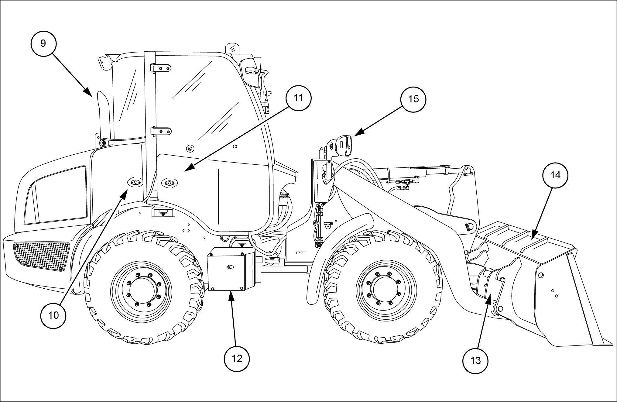
Product identification - Machine components
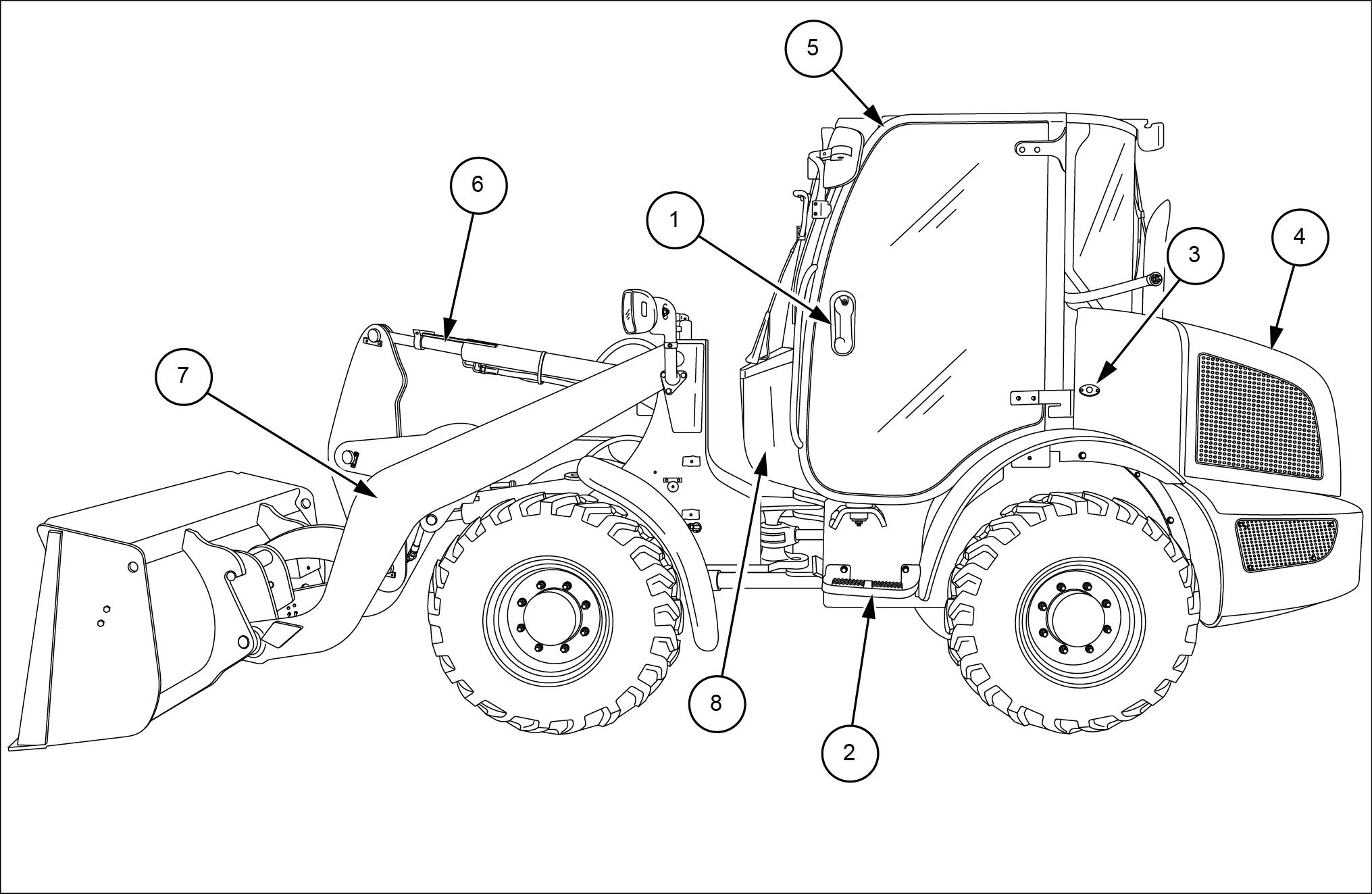
Cab door and hand holds
Steps
Fuel tank access)
Engine hood
LEIL14CWL0054FB 1
Roll Over Protection Structure (ROPS) and Falling Objects Protective Structure (FOPS) cab
Boom cylinder
Loader lift arms
Cab air filter access
Engine - Remove
NOTE: Emissions sensors mounted the exhaust stream are sensitive extreme Use tools that erate extreme such impact wrenches and will result damage emission A void using these tools during any service procedure close proximity emission sensors. the use these tools cannot remove the sensors using extreme caution prior performing any service
Park the machine level lower the bucket / attachment the
Drive the machine into such a position that the bores the holders are aligned one above the other Then secure with the pin The pin located inside the support the
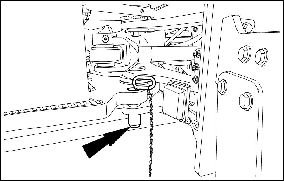
Stop the LEIL14CWL0005AB
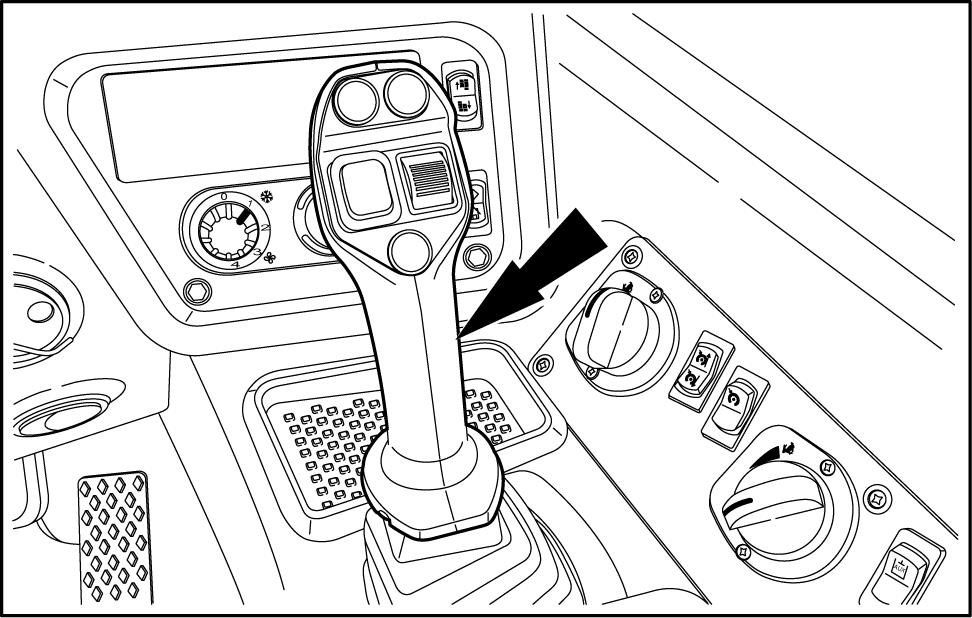
Keep all non - authorized personnel clear the T urn the ignition switch key the “ON”
Move the joystick slowly forward and backward and from the right - hand the left - hand approximately a dozen T urn the ignition key the OFF
Pump brakes approximately times bleed accumuBleed ride control accumulator (if equipped) with bleed screw
NOTE: before carrying out any service work the draulic necessary allow the system cool: the temperature should not more than ( )
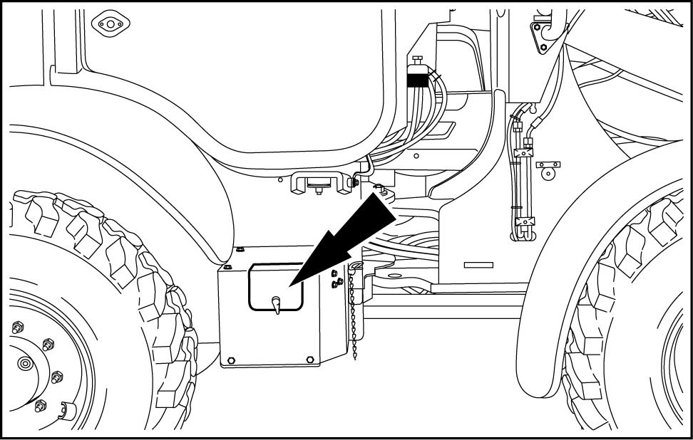
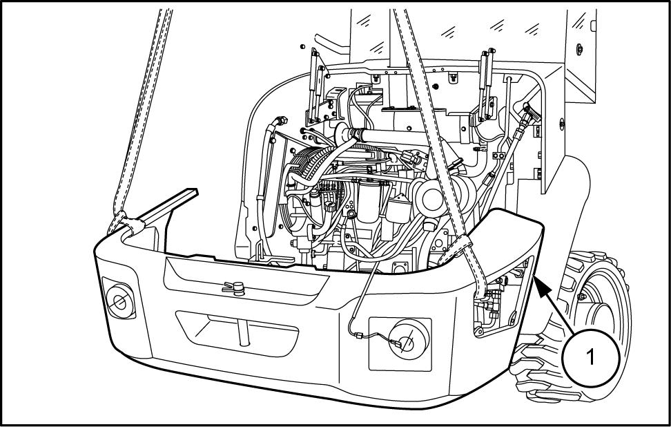
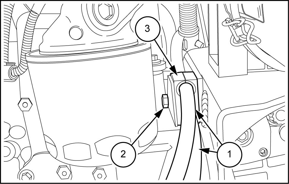
Open the outer panel access the battery main The battery main switch box located the right - hand side the below the operator ’ s
Engine - Engine and crankcase
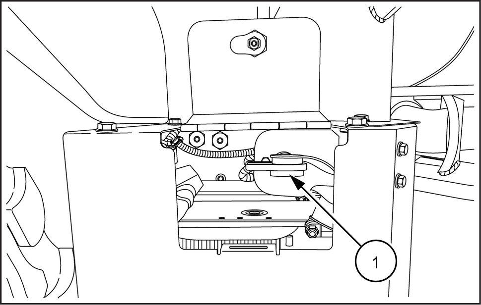
Put the battery main switch (1) the OFF position.
LEIL14CWL0017AA 4
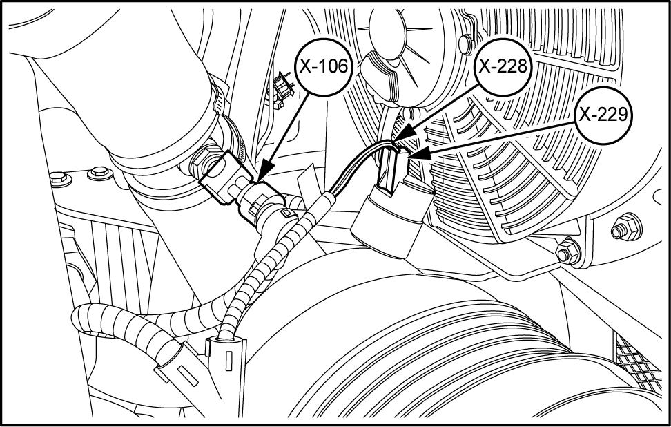
Disconnect the wiring harness - 228) and - 229) from the engine air filter
Disconnect the wiring harness - 106) from the air perature sensor
LEIL14CWL0171AB 5
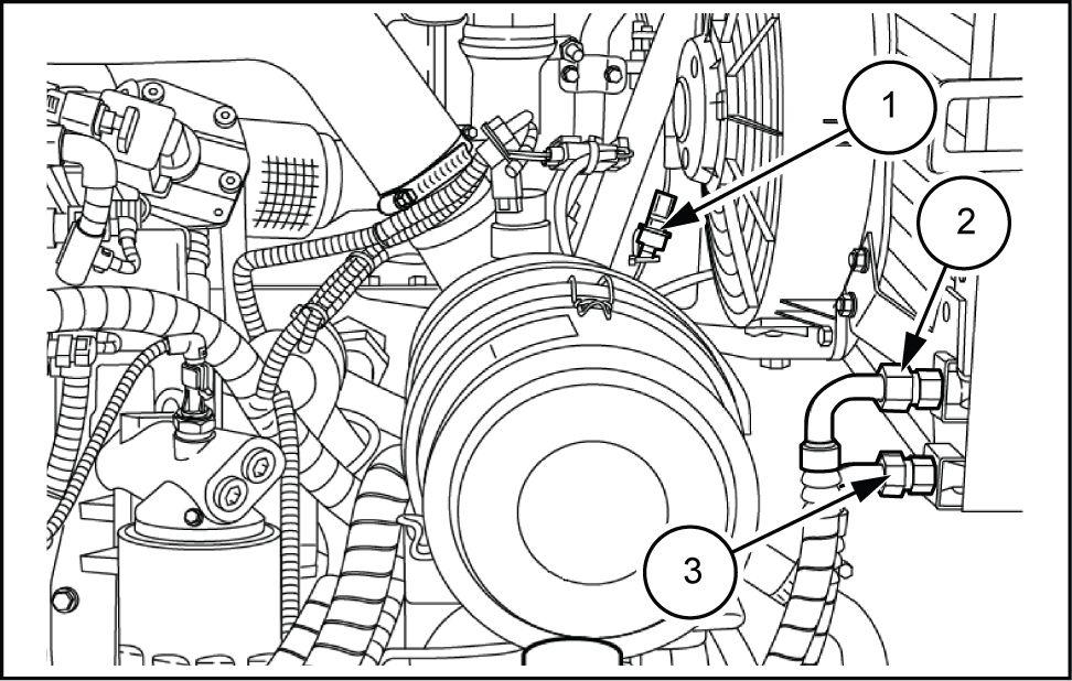
V ersions with air conditioning
Drain the air conditioning system and disconnect the fan electrical connector (1)
T and disconnect the condenser hoses (2) and (3)
LEIL14CWL0159A 6
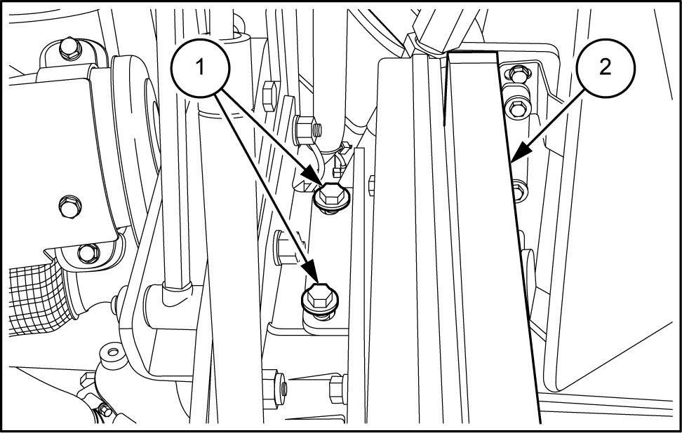
Remove the two lower bolts (1) the condenser bracket (2)
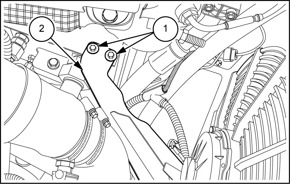
LEIL14CWL0160AB 7
Remove the two upper bolts (1) the condenser .
Remove the condenser (2)
All versions
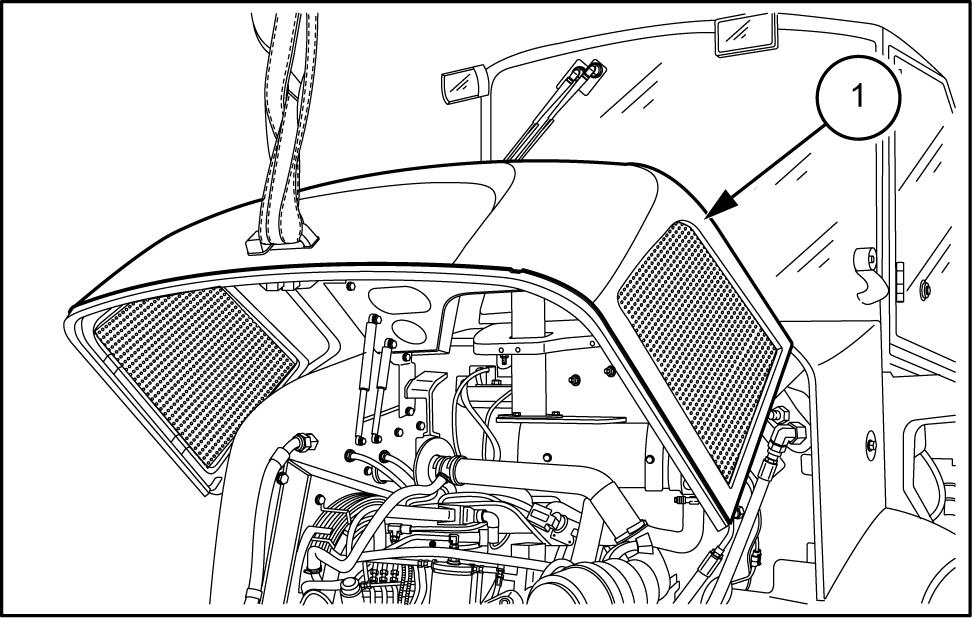
Secure the engine hood (1) with the nylon llifting
LEIL14CWL0161AB 8
LEIL14CWL0216AB 9
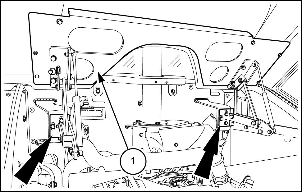
Have another person balance the hood and remove the hood hinge mounting bolts (arrows) from the chine
Carefully raise and remove the engine hood (1) from loader
Lower the engine hood onto suitable platform and disconnect lifting
LEIL14CWL0162AB
T and disconnect the left rear light connector (1)
Repeat this operation for the right rear light connector
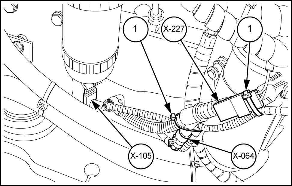
T and disconnect the water fuel wiring harness - 105)
T and disconnect the backup alarm wiring harness - 064)
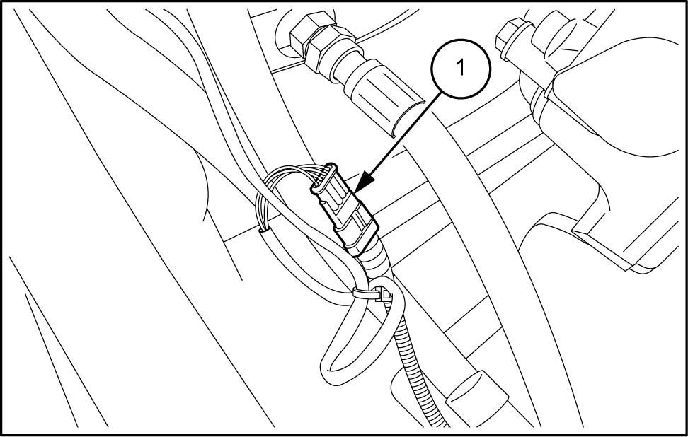
T and disconnect the filter pressure switch wiring ness - 227) . Cut the ties cable (1) .
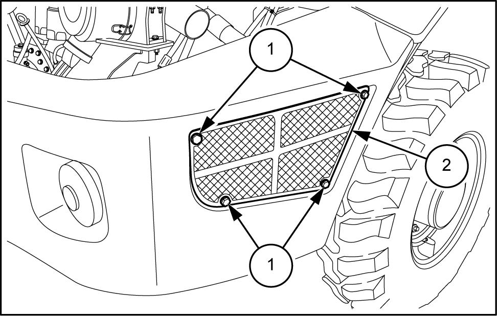
Remove the four mounting bolts (1) the right grid (2)
Remove the right grid (2) .
NOTE: repeat the same operation the left
Connect suitable lifting equipment counterweight fer Couterweight –
Remove the six bolts (arrows) the counterweight and remove
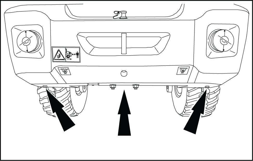
Slowly extract the counterweight (1) from rear sure all wire harness connections have been
Remove the counterweight (1) from the machine.
Lower the counterweight onto suitable platform and connect the lifting
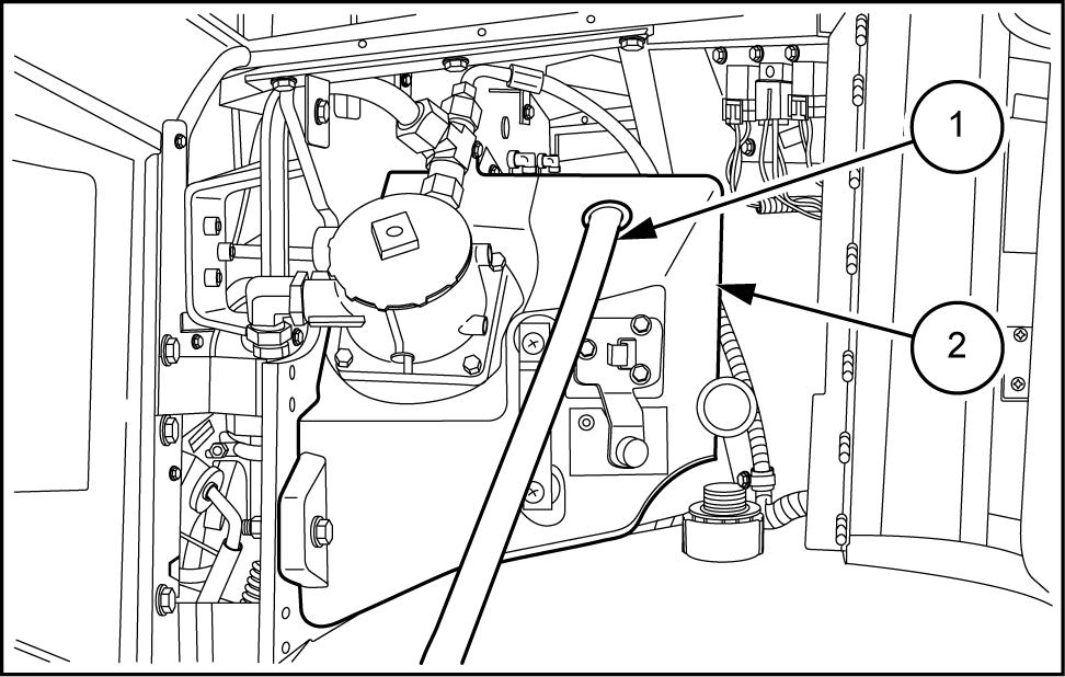
Remove the cap from the hydraulic tank (2) . into the the hose (1) connected a suction pump and suck the oil from the tank (2)
NOTE: use a suitable container for collection coolant and abide all local environmental laws for proper handling and
LEIL14CWL0219AB
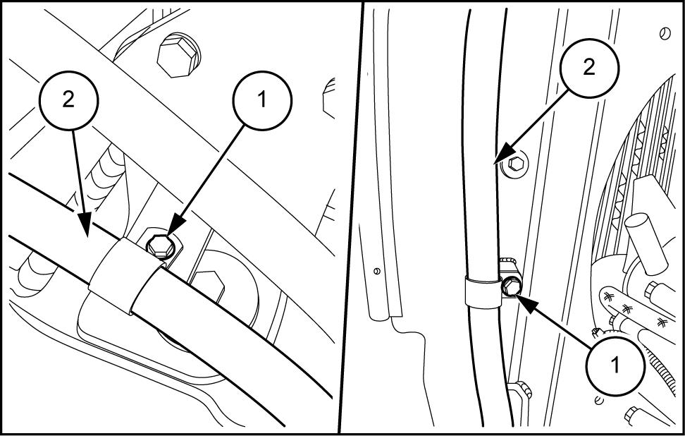
Loosen the clamp (2) the coolant hose (1) and connect from the radiator .
NOTE: use a suitable container for collection coolant and abide all local environmental laws for proper handling and disposal.
10. Unscrew the fitting and disconnect the hydraulic oil hose (3) from the radiator
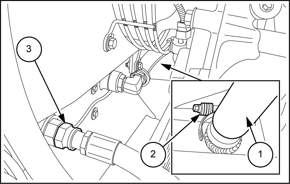
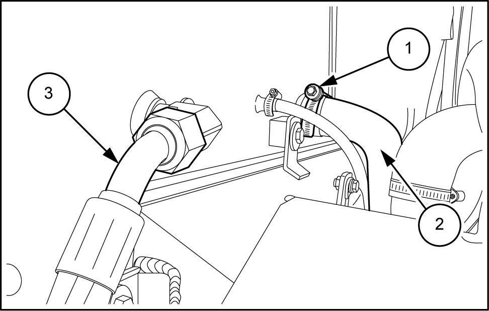
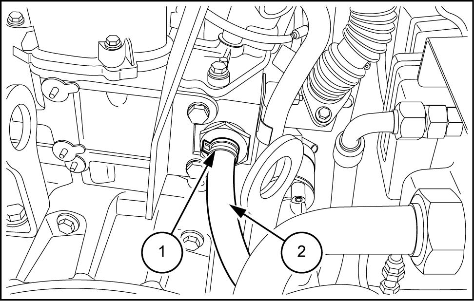
1 Loosen the clamp (1) and disconnect the coolant hose (2) from the radiator
Unscrew the fitting and disconnect the hydraulic oil hose (3) from the radiator
LEIL14CWL0232AB
LEIL14CWL0233AB
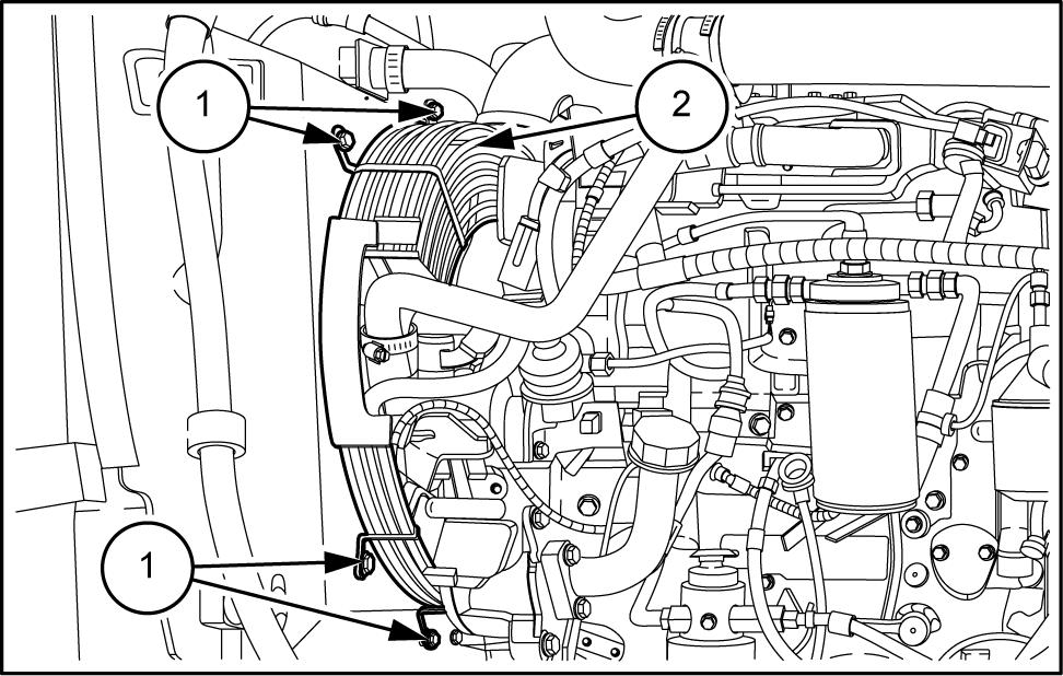
Remove the screws (1) securing the clamps the hydraulic oil hose (2)
LEIL14CWL0234AB
13. Remove the four screws (1) remove the fan guard (2)
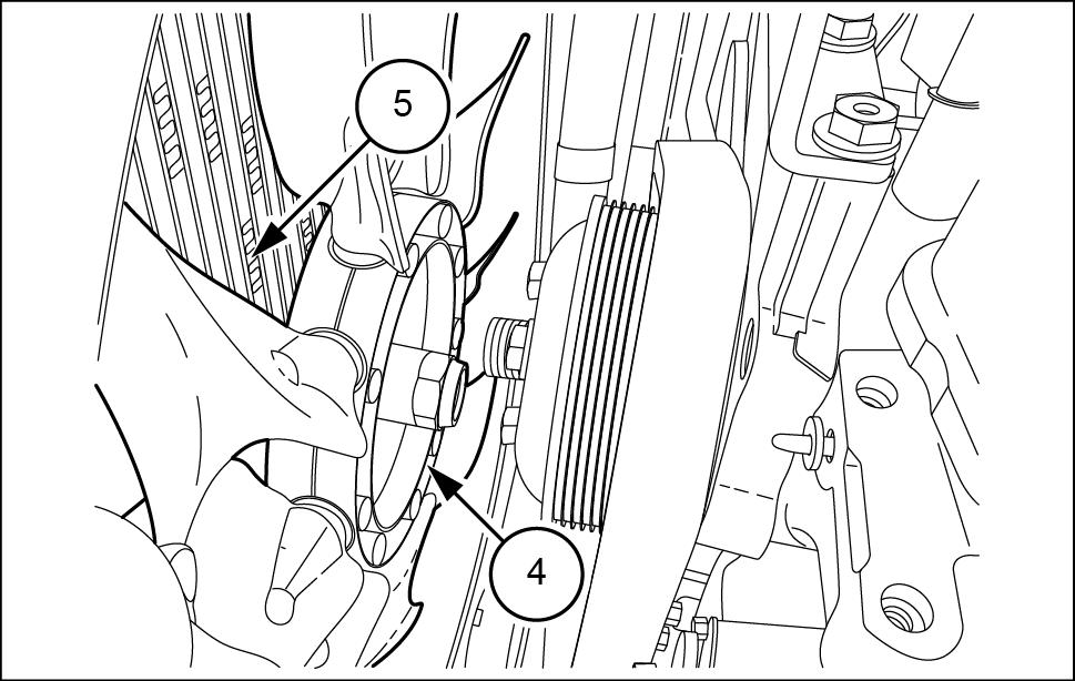
Loosen the nut (3) unscrew the fan (4)
The nut (3) left - handed: turn the nut (3) clockwise respect the engine loosen the nut (3)
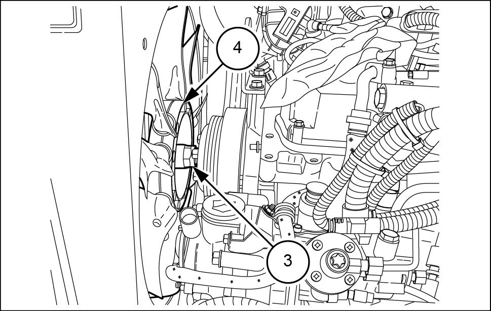
Lean the fan (4) against the radiator group (5)
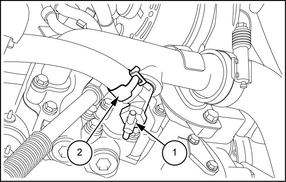
Remove the screw (1) and disconnect the earth strap (2) from the
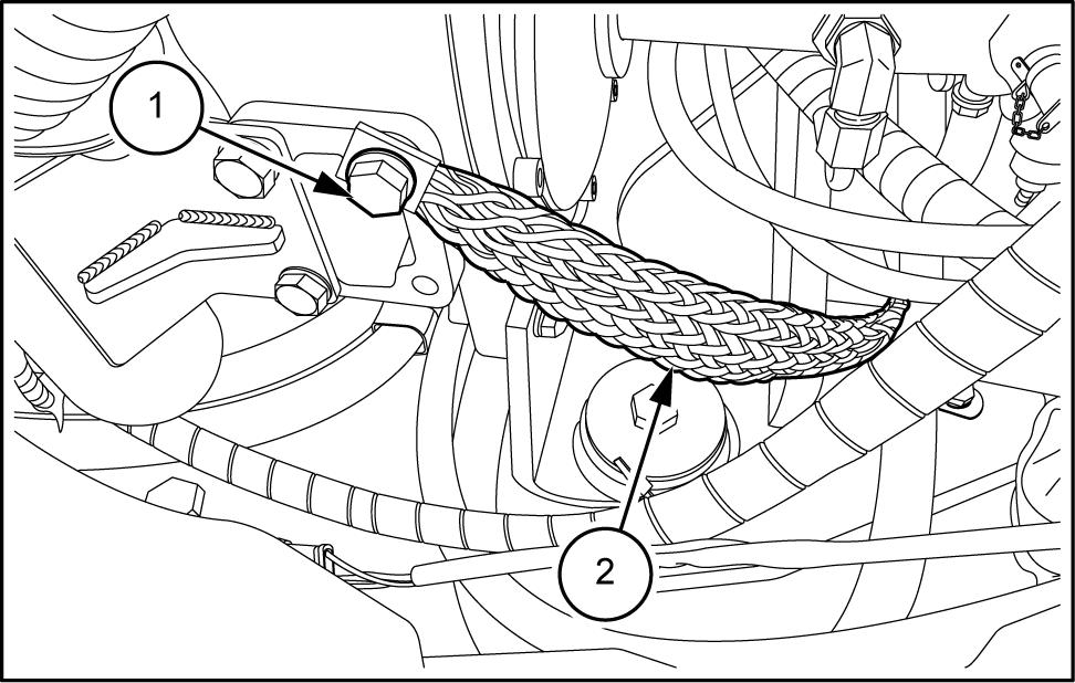
17. Loosen the clamp (1) and disconnect the oil steam recovery hose (2)
LEIL14CWL0220AB
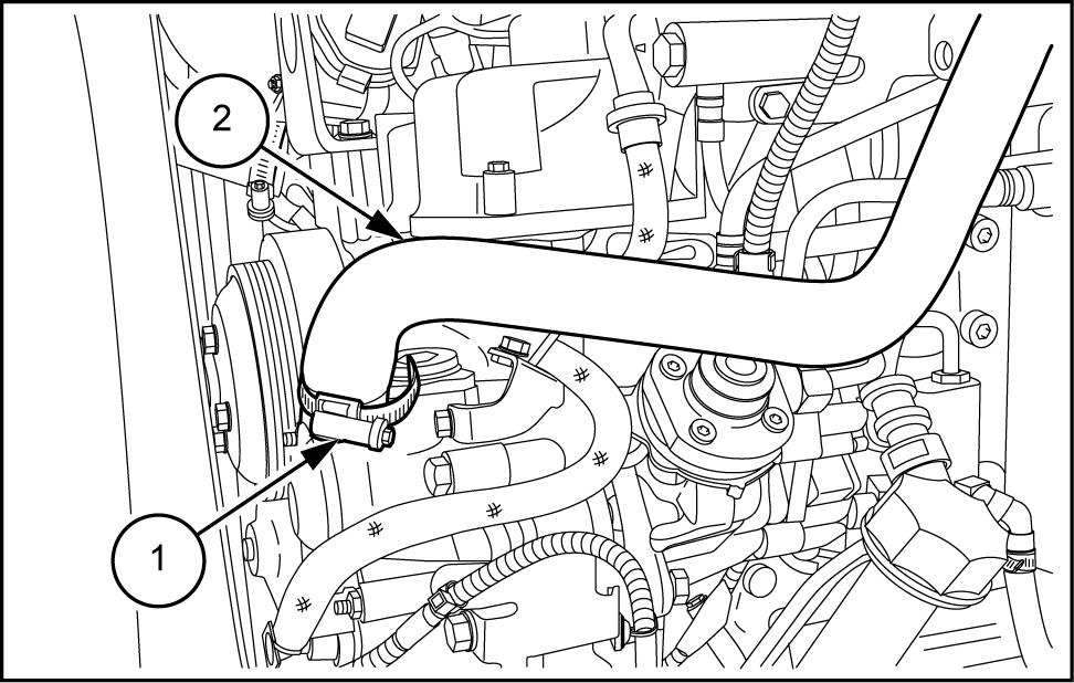
Loosen the clamp (1) and disconnect the air inlet hose (4)
. Remove the screws (2) from the bracket (3)
LEIL14CWL0221AB
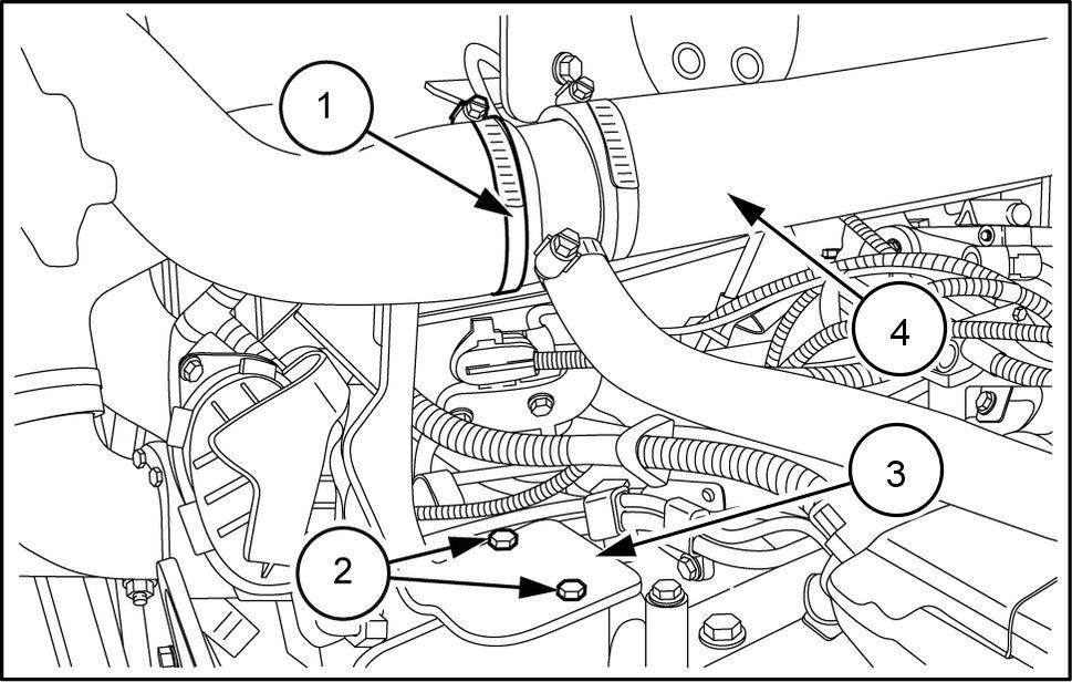
Remove the screw (2) release the air inlet hose (3) from the clamp (1)
LEIL14CWL0222AB
Remove the screw (2) the half guideway (3) for positioning fuel hoses (1)
LEIL14CWL0223AB
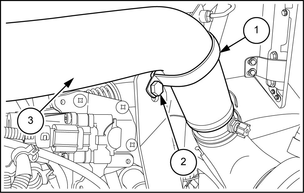
21. Remove the screws (1) the air filter bracket (2) .
Remove the air filter assembly (3) with the air inlet the oil vapor recovery pipe and bracket with O -
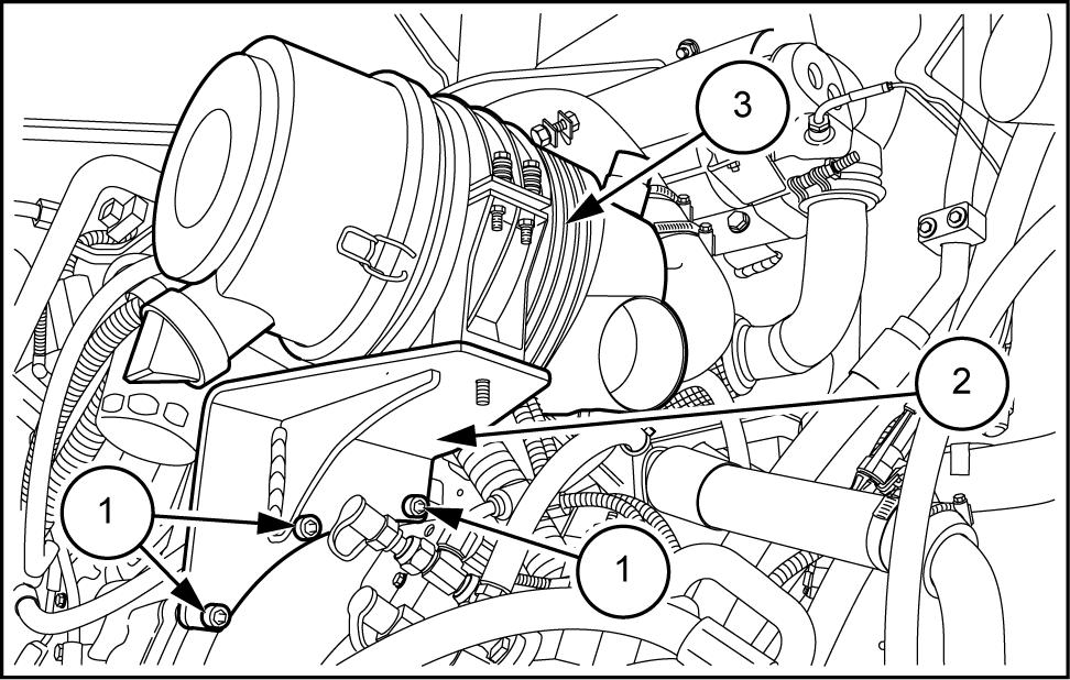
LEIL14CWL0224AB
Disconnect the wiring harness - 109) from the mediate connector signal.
Disconnect the wiring harness - 1 10) from the mediate connector injector
Disconnect the A / C clutch wiring harness - 226) (only air conditioning
Remove the clamp (1) and cut the ties cable (2) .
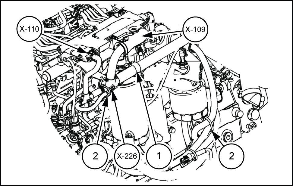
LEIL14CWL0172A
Behind the starter motor (1) , remove the screw (3) and disconnect the ground wiring harness - 232) , - 233) and - 234) .
Remove the ties cable (2)
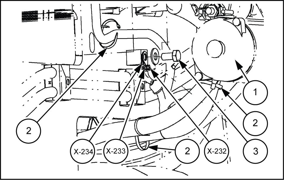
LEIL14CWL0174AB
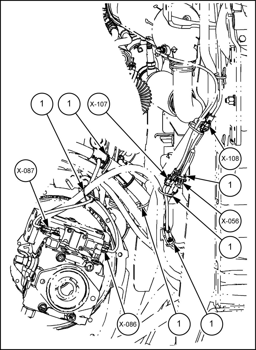
24. Fan condenser connector - 056) has already been disconnected when removing the condenser (only air conditioning
Disconnect reverse solenoid wiring harness - 086)
Disconnect the forward solenoid wiring harness - 087)
.
Disconnect the exhaust gas temperature sensor wiring harness - 107) and - 108)
Remove the ties cable (1)
LEIL14CWL0175BB
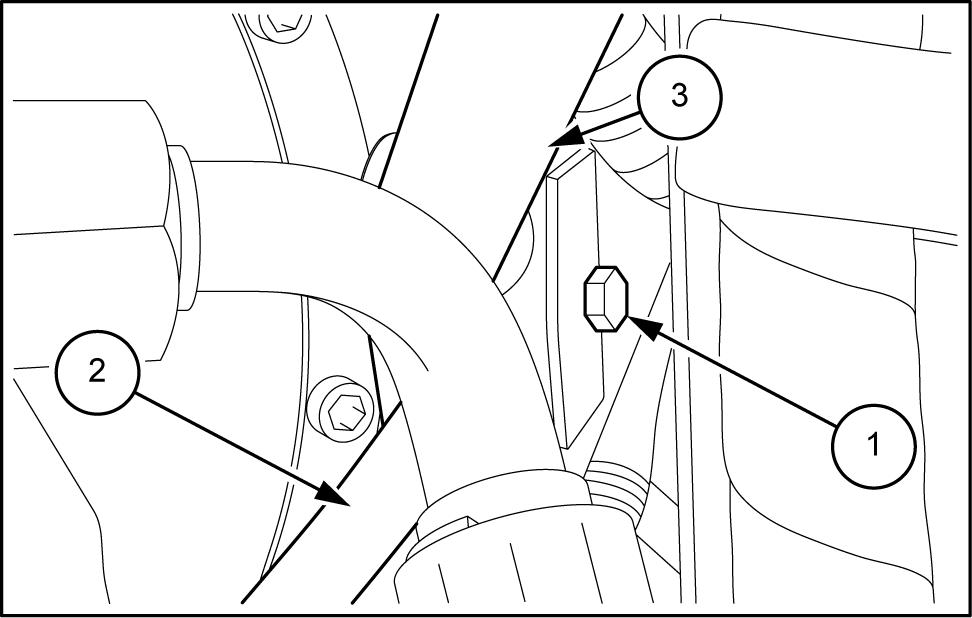
Remove the screws (1) securing the exhaust stack (2)
NOTE: the exhaust stack (2) must removed after the detachment the - Cat
Loosen the clamp (1) and disconnect the tion hose (2) from the - Cat system (3)
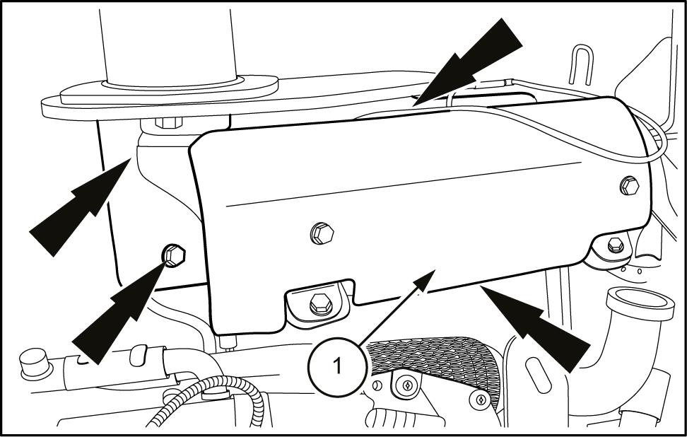
27. Remove the four screws (arrows) securing - Cat system (1) the
Remove the PM - Cat system (1) from the from the the exhaust
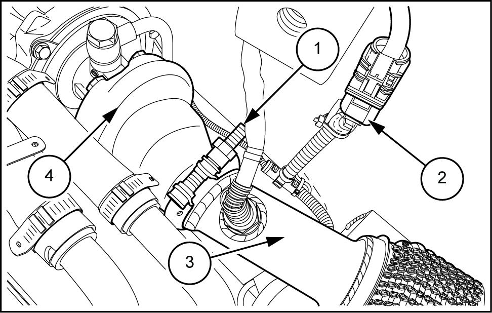
Disconnect the lambda probe connector (2) Loosen the clamp (1) and remove the compensation hose (3) from the turbocharger (4)
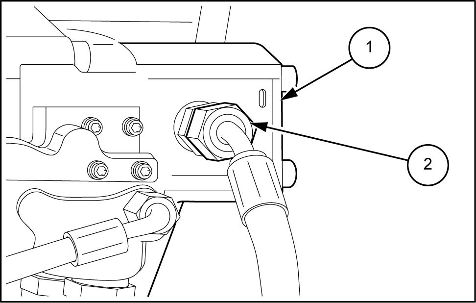
Acting from under the machine:
• turn f the tap (1) ;
• loosen the clamp (2) and disconnect the cab ing hose;
• open the tap (1) drain the coolant from the engine
NOTE: use a suitable container for collection coolant and abide all local environmental laws for proper handling and
From the right side the loosen the clamp (1) and disconnect the hose cab heating (2)
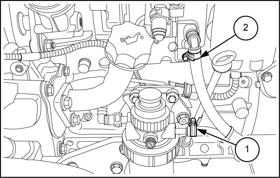
31. Remove the screw (1) the half guideway for tioning reverse hose (2) and forward hose (3)
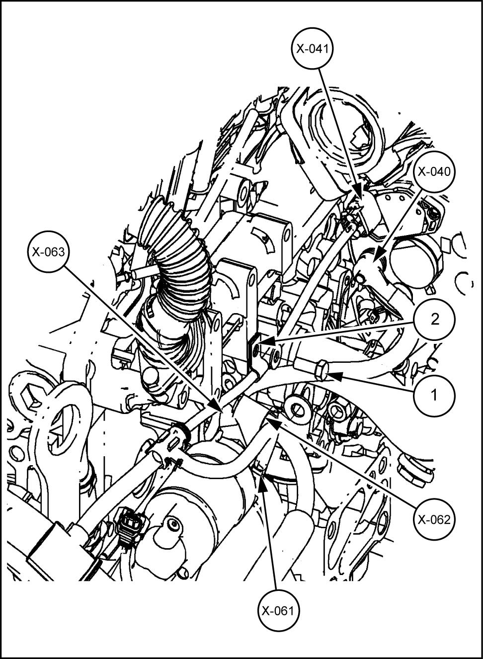
T and disconnect starter motor erminal 50) wiring harness - 061)
.
T and disconnect starter motor wiring harness - 062) and - 063)
T and disconnect alternator battery cable - 040)
T and disconnect alternator (D+) wiring harness - 041)
.
Unscrew the bolt (1) and remove the clamp (2) Remove eventually clamps and cut the ties cable not
Disconnect
34.
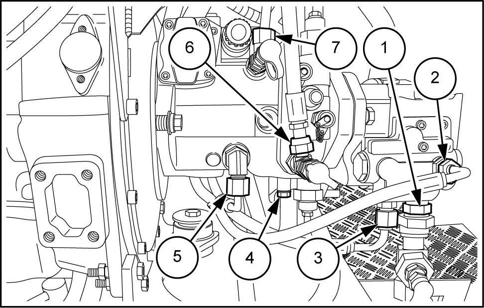
Unscrew the hydraulic fitting (1) , (2) and (3) and connect the hoses from the gear
Unscrew the hydraulic fitting (5) and (6) and nect the hoses from the hydrostatic
Remove the four screws and disconnect the pipe (4) from the hydrostatic pump.
Unscrew the hydraulic fitting (7) and disconnect the pipe from the hydrostatic
Unscrew the hydraulic fitting (1) and disconnect the hose from the hydrostatic pump.
Unscrew the hydraulic fitting (2) and disconnect the pipe from the hydrostatic
Remove the four screws and disconnect the pipe (4) from the hydrostatic
Remove the four screws and disconnect the pipe (3) from the gear
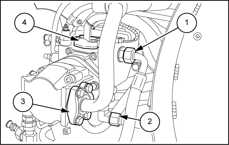
For the models equipped with auxiliary pump (1) , screw the hydraulic fitting (2) and disconnect the hose from the auxiliary pump.
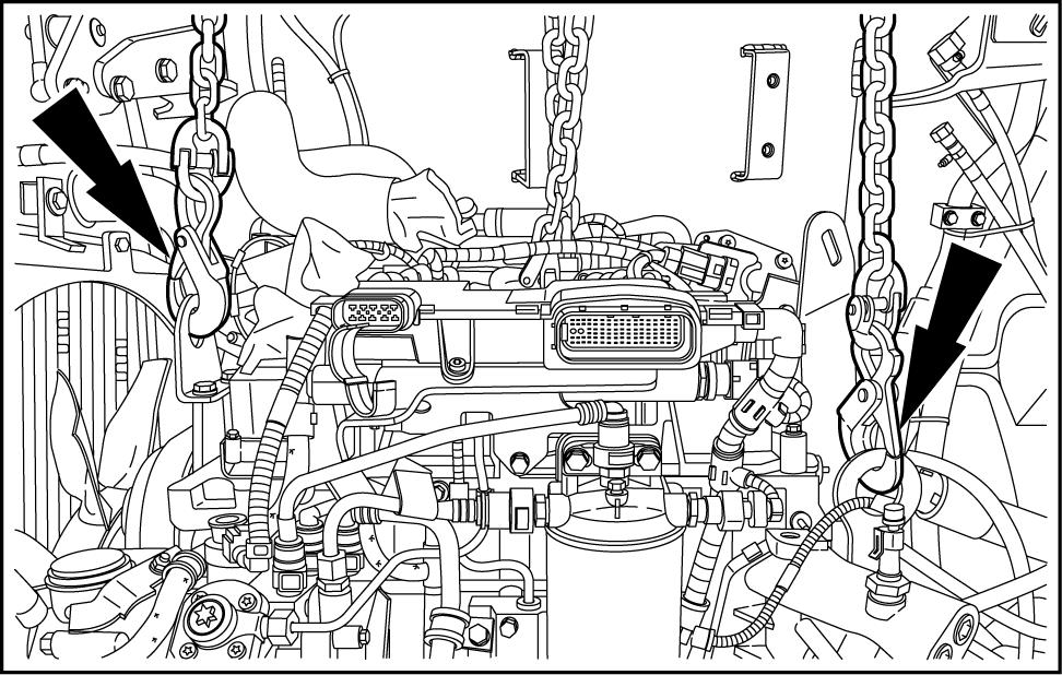
Connect suitable lifting equipment engine lifting
brackets T ake all slack lifting
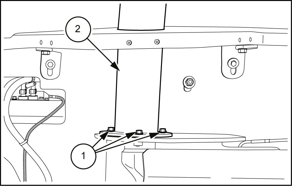
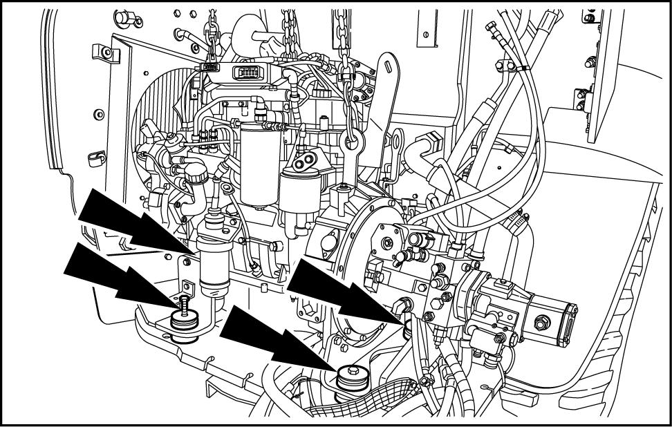
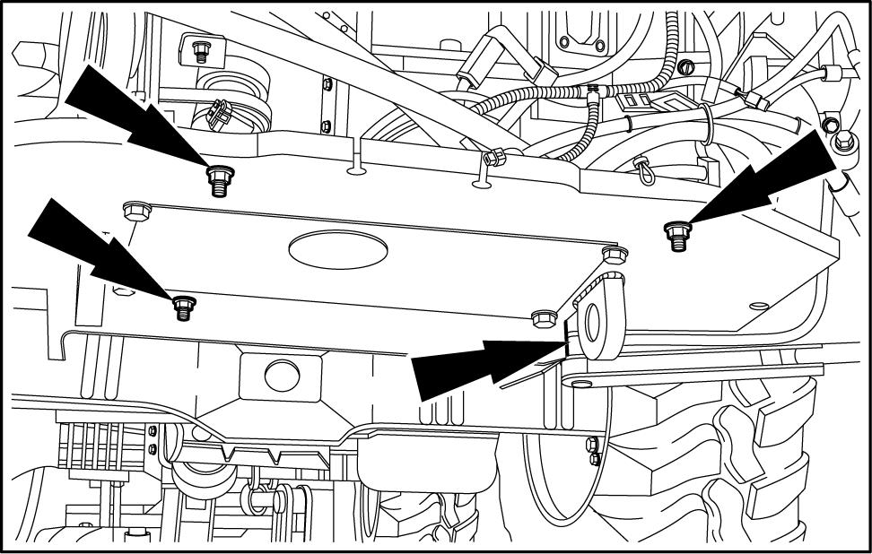
38. Remove the engine silent block (arrows) unscrewing the nuts from the lower part the Slowly raise engine from rear sure all wire harness connections and hoses have been nected and are clear the Remove engine from machine.
Engine - Install W ARNING
Hot liquid under pressure!
Never remove the filler cap the recovery tank cap while the engine running the coolant hot.
Let the system cool. T urn the filler cap the first notch and allow any pressure escape, and then remove the filler
Loosen the recovery tank cap slowly allow any pressure
Failure comply could result death serious injury . W0296A
NOTE: Emission sensors mounted the exhaust stream are sensitive extreme Use tools that erate extreme vibrations, such impact wrenches and hammers, will result damage emission sensors. A void using these tools during any service procedure close proximity emission the use these tools cannot remove the sensors using extreme prior performing any service
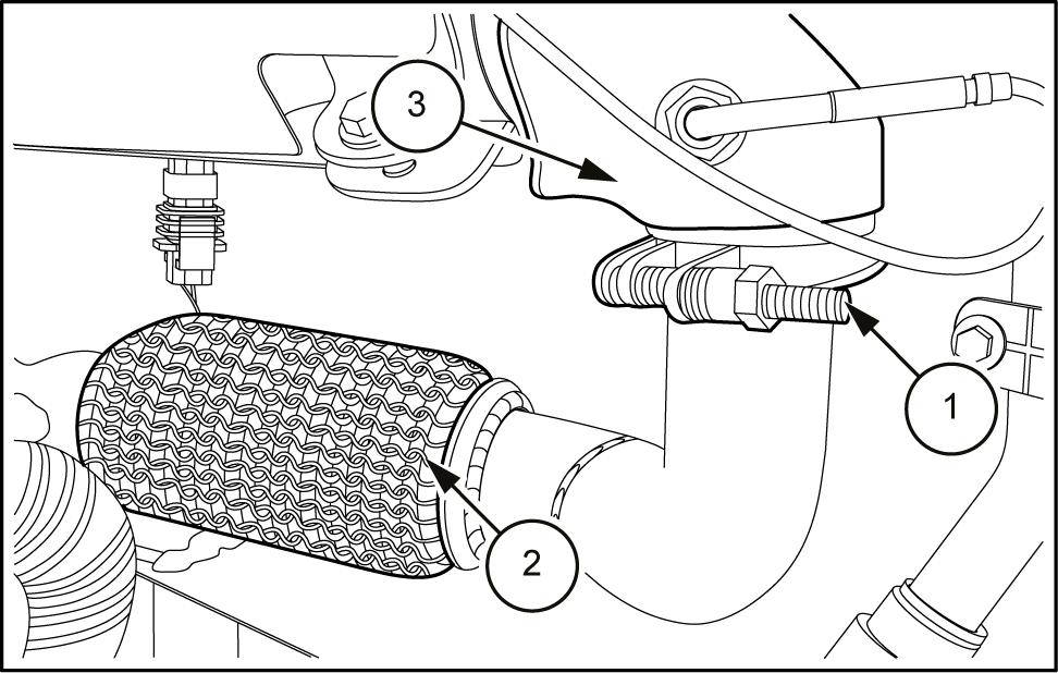
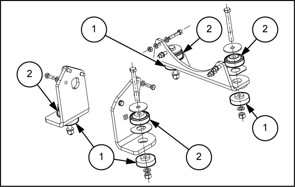
Inspect the engine the engine rubber tors require replacement, remove and discard the lators (1) and (2) Install new rubber isolator (2) , then rubber isolator (1)
Make sure that the tightening torque the fixing screws the brackets the engine 1 - 133 N·m () .
Attach suitable lifting device the engine and slowly move into position over the rear sure all harness connections and hoses are out the way positioned correctly for before lowering
Install the silent blocks (arrows) the
T
ighten the mounting bolts the engine a torque 244 - 298 N·m ( 180 - 220 )
LEIL14CWL0393AB 1
LEIL14CWL0235AB 2
LEIL14CWL0394AB 3
Disconnect lifting equipment from the engine lifting LEIL14CWL0236AB 4
For the models equipped with auxiliary pump (1) , connect the hydraulic hose the auxiliary pump and tighten the fitting (2)
LEIL14CWL0180AB 5
Connect the hydraulic pipe (3) the gear pump and tighten the four screws the half -
Connect the hydraulic pipe (4) the hydrostatic pump and tighten the four screws the half -
Connect the hydraulic hoses the hydrostatic pump and tighten the fittings (1) and (2)
LEIL14CWL0179AB 6
Connect the hydraulic hoses the gear pump and tighten the fittings (1) , (2) and (3)
Connect the hydraulic hoses the hydrostatic pump and tighten the fittings (5) and (6) .
Connect the hydraulic pipe (4) the hydrostatic pump and tighten the four screws the half -
Connect the hydraulic pipe the hydrostatic pump and tighten the fitting (7)