DOWNLOAD SERVICE MANUAL
7
8
9

TABLEOF CONTENTS


SERVICE MANUAL INTRODUCTION
DOWNLOAD SERVICE MANUAL
This service manual has been prepared with Page Numbers the latest service information available. Troubleshooting, removal, disassembly, inspection and installation procedures, and complete specifications and tightening references can be found in most sections. Some sections have drawings but no written procedure because the job is so easily done. This service manual is one of the most important tools available to the service technician.
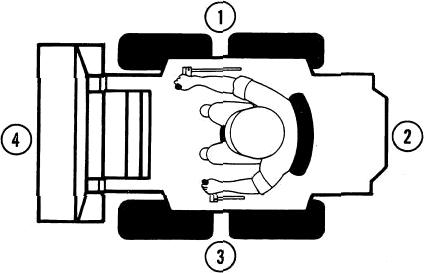
Right, Left, Front, and Rear
The terms right-hand and left-hand and front and rear as used in this manual indicate the right and left sides, and front and rear of the machine as seen from the operator's seat for correct operation ot the machine or attachment.
Text
If the service manual Is for more than one machine or different models of components (planetary axles, gear boxes, control valves, etc.) the procedures have the steps necessary to service each model.
Table ofConeni*
A Table of Contents is in the front of this manual. The Table of Contents shows the main divisions and the sections that are in each division. The individual sections, where necessary, have a Table of Contents on the cover or second page of that section.
All page numbers are made of two numbers separated by a dash, such as 4002-9. The number before the dash is the section number. The number following the dash is the page number in that section. Page numbers will be found at the upper right or left of each page.
Illustrations and Photos
Illustrations are put as near as possible to the text and are to be used as part of the text. Photos normally are put below the step to which they apply.
Special Tools
Special tools are needed to remove and install, disassemble and assemble, check, and adjust some component parts of this machine. Some special tools can be easily made locally and the necessary information to make the tool is in this service manual. Other special tools are more difficult to make locally and are available from Service Tools in the U.S. and from Jobborn Manufacturing in Canada. Use these tools according to the instructions in this service manual for your personal safety and to do the job correctly.
Order special tools from either of the following
companies: Service Tools P.O. Box 314 Owatonna, Minnesota 55060
Jobborn Manufacturing Co. 97 Frid Street Hamilton, Ontario L8P 4M3 Canada

COłTtponents


ROPs ser:al g„
LOCated łnaige pper-l•larią COmer


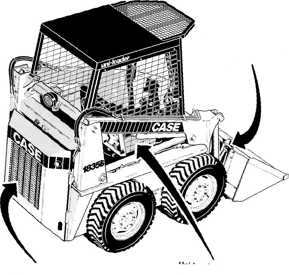

Buaket Pary No. Spilł Guanj LOCated on BuCketBack

ieset & Gasoi * fafed Lower L. Side Seriai NO '•^- <ocated Od L•H Of I•leeI P/ate n Side

TORQUE SPECIFICATIONS
{Use the following torques when special torques are not given.)
Grade S Bolts, Nuts and Studs (Dry Threads)


Grade 8 Bolts, Nuts and Studs (Dry Threads)
2549-3282
1/4-20
10-15 14-20 1.4-2.1 1/4-28 NF 15-2D
5/16-18
3/8-16


1/2-13
9/16-12
5/8-11

1-8 NC 810-990 1098-1342 112-137 1-12 NF 900-1100 1220-1491 124-152
1-1/8-7 NC 1150-1400 1559-1898 159-194 1-1/8-12 NF 1295-1585 1756-2149 179-219
1-1/4-7 NC 1640-2000 2224-2712 227-277 1-1/4-12 NF 1800-2200 2441-2983 249-304
1-3/8-6 NC 2140-2620 2902-3553 296-362 1-3/B-12 NF 2450-3000 3321-4068 339-415
1-1/2-6 NC 2845-3475 3858-4712 393-480 1-1/2-12 NF 3200-3900 4339-5288 442-539
TORQUE SPECIFICATIONS FOR STEEL HYDRAULIC FITTINGS
Split Flange Mounting Bolts (Grade 5, Dry Threads)
ENGINE REMOVALAND INSTALLATION, ACCESSORIES
TABLE OF CONTENTS

ENGINE REMOVAL
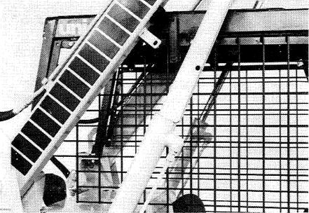
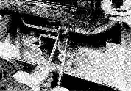
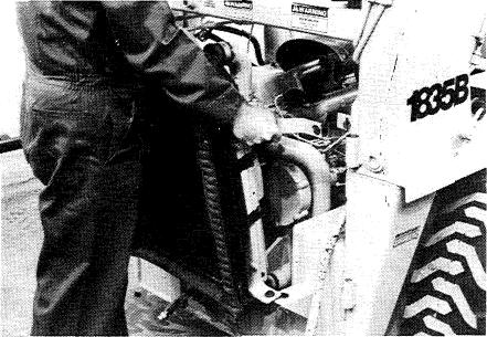
1. Remove the pins that hold the strut and lower the strut.
2. Start the engine and raise the Loader frame until the strut is against the end of the Iift cylinder. Install the pins in the strut.
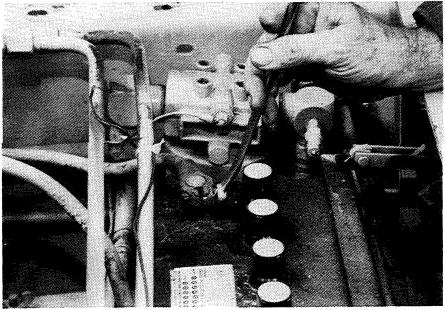
5. Cut the tie straps that holdthe wiring harness.
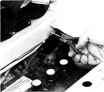
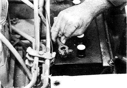
6. Loosen the cap screws that hold the instru- ment cluster.
7. Hold the instrument cluster and remove the cap screws, lock washers, flat washers, and spa- cers.
32011B
32O2Y
3@237
3. Remove the seat.
320120R
4. If equipped with lamps, cut the wire tothe front lamps.
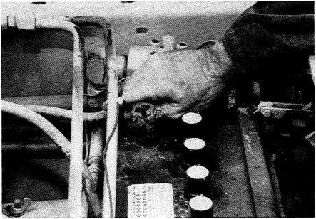
8. Put the instrument cluster out of the way.
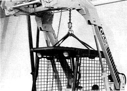
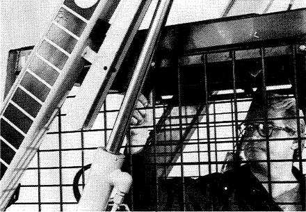
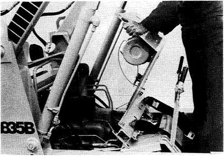
9. Connect lifting equipment to the ROPS canopy-
10.
11.
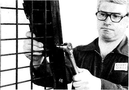
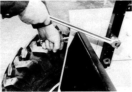
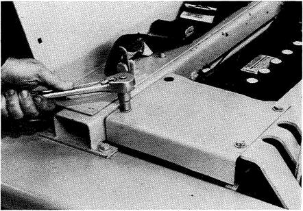
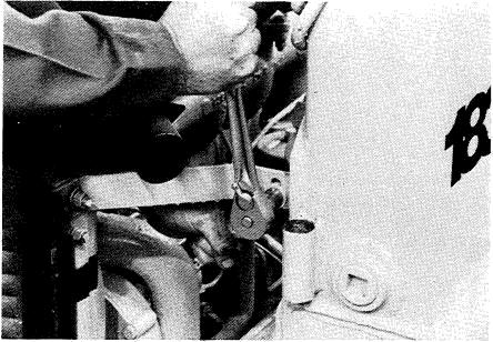
12. Loosen andremove thenuts,lock washers and bolts that fasten the front posts to the frame.
13. Start the engine, hold the strut away from the lift cylinder and Tower the loader frame.
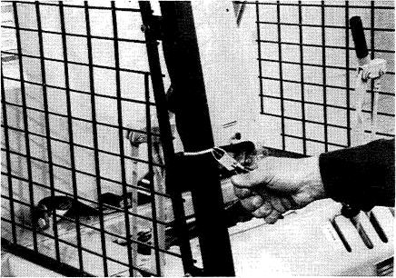
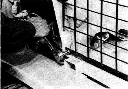
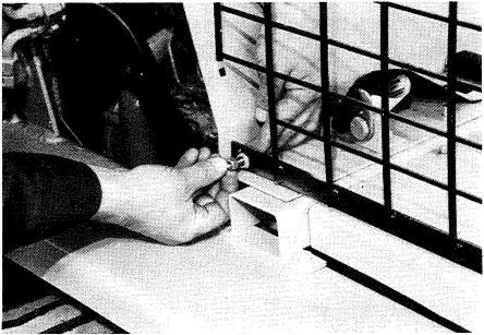
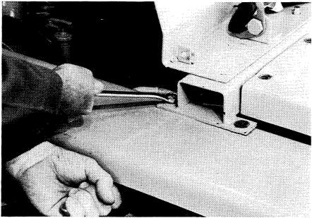
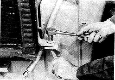
14. Loosen and remove the nut and lock washer from each bolt that fastens the posts to the
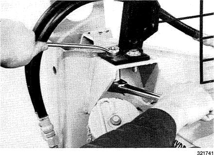
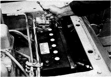
Loosen the nut on the bolt that fastens each screen to the heat shield.
Remove the nuts, lock washers, flat washers, and bolts.
frame.
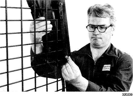
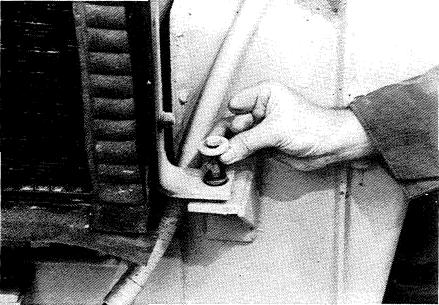
15. Remove the bolts.
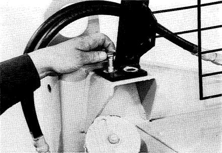
16. Carefully raise the ROPS canopy until the ROPS canopy is free of the machine.
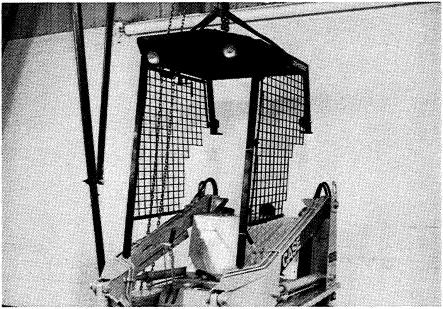
17. Remove the ROPS canopy.
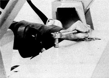
18. Loosen and remove the
hold the rear of the heat
19. Loosen end remove the cap screws at the rear of the right cover.
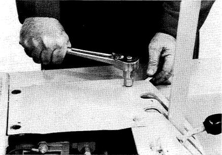
20. Loosen and remove the nuts, lock washers, flat washers, and bolts from each side of the cross- member.
nuts, lock washers, flat washers, and bolts that
shield.
21. Loosen and remove the cap screws that hold the left cover.
22. Remove the cover.
23. Loosen and remove the cap screws and lock washers that hold the charge circuit filter.
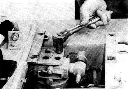
24. Loosen and remove the cap screw(s) and clamp(s) that fasten the tubes to the bottom of the crossmember.
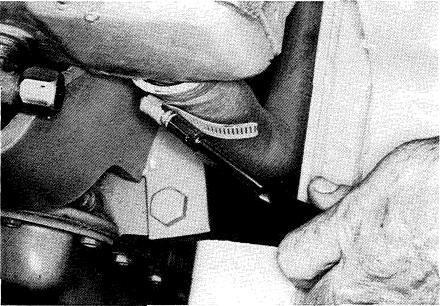
25. Loosen the clamp on the hose at the air cleaner and remove the hose. Oiesel engine shown, hose at other end for gasoline engine.
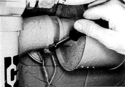
26. Disconnect the wires from theswitch for theair cleaner warning lamp.
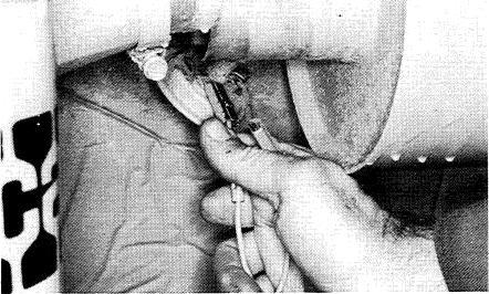
27. If equipped with ether injection, disconnect the tube from the intake manifold.
X2BJ0
28. Remove the heat shield.
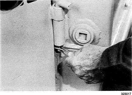
29. Remove the hair pins from the pins that hold the door.
30. Remove the pins.
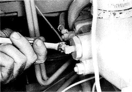
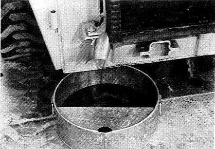
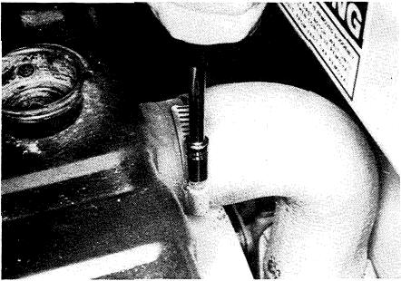
32. Loosen and remove the radiator cap, open the drain valve. and drainthe radiator.
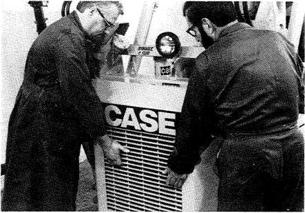
33. Disconnect the hoses at the bottom of the radi- ator.
34. Installasteel plug ineach hoseanda steel cap on each fitting.
35. Loosen and remove the nuts, lock washers, flat washers, and bolts that hold the top radiator sup-
36. Loosen and remove the self-locking nuts from the bolts that hold the bottom radiator supports.
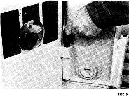
31. Remove the door.
37. Remove the bolts and flat washers.
38. Loosen the clamp on the bottom radiator hose and remove the bottom radiator hose 1rom the ra- diator.
39. Loosen the clamp on the top radiator hose and remove the top radiator hose from the radiator.
40. Remove the radiator.
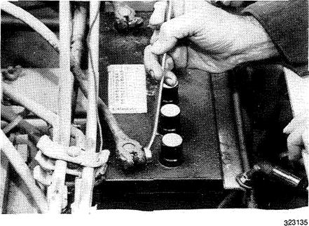
41. Loosen the nut on the bolt in the clamp for the negative battery cable.
42. Remove the negative battery cable.
43. Loosen the nut on the bolt in theclamp for the positive battery cable.
44. Remove the positive battery cable.
46. Remove the battery.
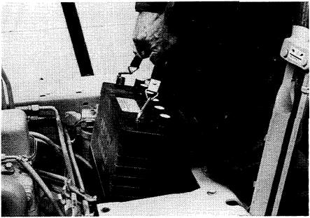
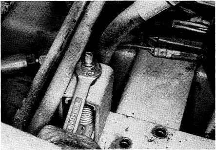
and remove the nuts, lock washers, and bolts that hold the battery carrier.
3@141
47. Loosen
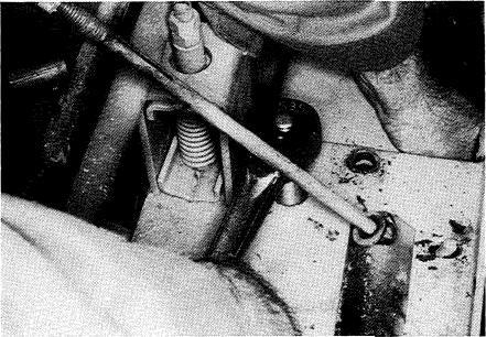
45. Loosen the nuts that hold the battery holder. 48. Loosen and remove the nuts from the neutral control rod.