

MAINTENANCE SAFETY
Instructions are necessary before operating or servicing machine. Read and understand the Operation & Maintenance Manual, Operator’s Handbook and signs (decals) on machine. Follow warnings and instructions in the manuals when making repairs, adjustments or servicing. Check for correct function after adjustments, repairs or service. Untrained operators and failure to follow instructions can cause injury or death.
Safety Alert Symbol: This symbol with a warning statement, means: “Warning, be alert! Your safety is involved!” Carefully read the message that follows.
Never service the Bobcat SkidSteer Loader without instructions.
Use the correct procedure to lift or lower operator cab.
Cleaning and maintenance are required daily.
Have good ventilation when welding or grinding painted parts. Wear dust mask when grinding painted parts. Toxic dust and gas can be produced. Avoid exhaust fume leaks which can kill without warning. Exhaust system must be tightly sealed.
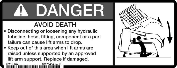
Disconnecting or loosening any hydraulic tubeline, hose, fitting, component or a part failure can cause lift arms to drop. Do not go under lift arms when raised unless supported by an approved lift arm support device. Replace it if damaged.
Never work on loader with lift arms up unless lift arms are held by an approved lift arm support device. Replace if damaged. Never modify equipment or add attachments not approved by Bobcat Company.
Stop, cool and clean engine of flammable materials before checking fluids.
Never service or adjust loader with the engine running unless instructed to do so in the manual.
Avoid contact with leaking hydraulic fluid or diesel fuel under pressure. It can penetrate the skin or eyes.
Never fill fuel tank with engine running, while smoking or when near open flame.
Keep body, jewelry and clothing away from moving parts, electrical contact, hot parts and exhaust.
Wear eye protection to guard from battery acid, compressed springs, fluids under pressure and flying debris when engines are running or tools are used. Use eye protection approved for type of welding. Keep rear door closed except for service. Close and latch door before operating the loader.
Lead-acid batteries produce flammable and explosive gases. Keep arcs, sparks, flames and lighted tobacco away from batteries. Batteries contain acid which burns eyes or skin on contact. Wear protective clothing. If acid contacts body, flush well with water. For eye contact flush well and get immediate medical attention.
Maintenance procedures which are given in the Operation & Maintenance Manual can be performed by the owner/ operator without any specific technical training. Maintenance procedures which are not in the Operation & Maintenance Manual must be performed ONLY BY QUALIFIED BOBCAT SERVICE PERSONNEL. Always use genuine Bobcat replacement parts. The Service Safety Training Course is available from your Bobcat dealer.
ACCESS PANEL (INSIDE).....................................50-01
ACCESS PANEL (INSIDE) (SJC)...........................50-01
AIR CLEANER........................................................70-01
AIR CLEANER SERVICE.......................................10-01
AIR CONDITIONING SYSTEM FLOW...................80-01
ALTERNATOR........................................................60-01
BACK-UP ALARM SYSTEM...................................60-01
BATTERY................................................................60-01
BLOWER FAN........................................................80-01
BOBCAT CONTROLLER (ACS)............................60-01
BOBCAT CONTROLLER (MAIN)............................60-01
BOBCAT CONTROLLER (SJC) (DRIVE)...............60-01
BOBCAT INTERLOCK CONTROL SYSTEM (BICS)...................................................60-01
BOB-TACH (HAND LEVER)........................10-01, 50-01
BOB-TACH (POWER).............................................10-01
BOB-TACH ([POWER-OPTION).............................50-01
BOB-TACH (POWER) BLOCK................................20-01
BRAKE (SINGLE SPEED)......................................40-01
BRAKE (TWO-SPEED)...........................................40-01
BUCKET POSITION VALVE...................................20-01
CALIBRATION........................................................60-01
CAMSHAFT AND TIMING GEARS.........................70-01
CASE DRAIN FILTER.............................................30-01
CHAINCASE...........................................................40-01
CHARGE PRESSURE ...........................................30-01
COMPRESSOR......................................................80-01
CONDENSER.........................................................80-01
CONTROL HANDLE/LEVER..................................50-01
CONTROL HANDLE/LEVER (ACS).......................50-01
CONTROL HANDLE/LEVER (SJC)........................50-01
CONTROL PANEL..................................................50-01
CONTROL PANEL (SJC)........................................50-01
CONTROL PANEL SETUP.....................................60-01
CONTROL PEDALS AND LINKAGE......................50-01
CONTROL PEDALS (ACS)....................................50-01
CONTROL SYSTEM (ACS)....................................60-01
CONVERSIONS................................................SPEC-01
CRANKSHAFT AND PISTONS .............................70-01
CYLINDER (BOB-TACH)........................................20-01
CYLINDER (LIFT)...................................................20-01
CYLINDER (TILT)...................................................20-01
CYLINDER HEAD...................................................70-01
DIAGNOSTICS SERVICE CODES.........................60-01
DRIVE BELT...........................................................30-01
DRIVE COMPONENTS..........................................40-01
ELECTRICAL/HYD. CONTROLS...........................60-01
ELECTRICAL/HYD. CONTROLS
REFERENCE (SJC)..............................................60-01
ELECTRICAL SYSTEM INFORMATION................60-01
ENGINE COOLING SYSTEM.................................10-01
ENGINE LUBRICATION SYSTEM .........................10-01
ENGINE COOLING SYSTEM.................................70-01
ENGINE INFORMATION.........................................70-01
ENGINE SPEED CONTROL...................................70-01
ENGINE SPEED CONTROL (SJC).........................70-01
EVAPORATOR........................................................80-01
EVAPORATOR/HEATER UNIT................................80-01
EXPANSION VALVE................................................80-01
FINAL DRIVE TRANSMISSION (CHAINCASE)......10-01
FLYWHEEL AND HOUSING...................................70-01
FLYWHEEL RPM SENSOR....................................60-01
FRONT AUXILIARY HYDRAULIC COUPLER BLOCK...............................................20-01
FUEL SYSTEM.............................................10-01, 70-01
HYDRAULIC CONNECTION SPECS...............SPEC-01
HYDRAULIC CONTROL VALVE (ACS) OR (SJC)..20-01
HYDRAULIC CONTROL VALVE (STANDARD)......20-01
HYDRAULIC/HYDROSTATIC FILTERS..................20-01
HYDRAULIC FLUID RESERVOIR..........................20-01
HYDRAULIC/HYDROSTATIC FLUID SPECIFICATIONS................................SPEC-01
HYDRAULIC/HYDROSTATIC SYSTEM..................10-01
HYDRAULIC PUMP (STANDARD)..........................20-01
HYDRAULIC PUMP (STANDARD) (HIGH FLOW)..20-01
HYDRAULIC PUMP (SJC)......................................20-01
HYDRAULIC PUMP (SJC) (HIGH FLOW)...............20-01
HYDRAULIC SYSTEM INFORMATION..................20-01
HYDROSTATIC MOTOR.........................................30-01
HYDROSTATIC MOTOR (TWO SPEED)................30-01
HYDROSTATIC MOTOR CARRIER (SINGLE ANDTWO-SPEED WITH MANUAL CONTROLS).........................................................30-01
HYDROSTATIC MOTOR CARRIER (SINGLE ANDTWO-SPEED WITH SJC CONTROLS).........................................................30-01
HYDROSTATIC PUMP............................................30-01
HYDROSTATIC PUMP (SJC)..................................30-01
HYDROSTATIC SYSTEM INFORMATION..............30-01
INSTRUMENT PANELS .........................................60-01
ALPHABETICAL INDEX (CONT’D)
LIFT ARMS..............................................................50-01
LIFT ARM BYPASS CONTROL VALVE...................20-01
LIFT ARM SUPPORT DEVICE................................10-01
LIFTING AND BLOCKING THE LOADER...............10-01
LIGHTS....................................................................60-01
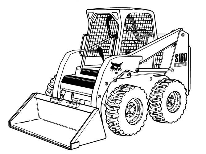
S150 LOADER SPECIFICATIONS....................SPEC-01
S160 LOADER SPECIFICATIONS....................SPEC-01
LOADER STORAGE AND RETURN TO SERVICE10-01
LUBRICATING THE LOADER.................................10-01
LUBRICATION SYSTEM.........................................70-01
MAIN RELIEF VALVE..............................................20-01
MAINTENANCE CLOCK.........................................60-01
MUFFLER................................................................70-01
OIL COOLER...........................................................20-01
OPERATOR CAB..........................................10-01, 50-01
OPERATOR SEAT...................................................50-01
OPERATOR SEAT (SUSPENSION)........................50-01
PASSWORD SETUP (IF EQUIPPED WITH KEYLESS START).................................................60-01
PIVOT PINS.............................................................10-01
REAR AUXILIARY DIVERTER VALVE....................20-01
REAR DOOR ..........................................................50-01
REAR GRILL ..........................................................50-01
RECEIVER/DRIER..................................................80-01
REGULAR MAINTENANCE....................................80-01
REMOTE START TOOL KIT-MEL1563...................10-01
REMOTE START TOOL (SERVICE TOOL) ‘ KIT - 6689779........................................................10-01
SEAT BAR...............................................................50-01
SEAT BAR SENSOR...............................................60-01
SERVICE PC (LAPTOP COMPUTER)....................60-01
SERVICE SCHEDULE.............................................10-01
SPARK ARRESTOR MUFFLER..............................10-01
STARTER................................................................60-01
STEERING DRIFT COMPENSATION.....................60-01
STOPPING THE ENGINE AND LEAVING THE LOADER.......................................10-01
SYSTEM CHARGING AND RECLAMATION..........80-01
THERMOSTAT.........................................................80-01
TORQUE SPECIFICATIONS FOR BOLTS........SPEC-01
TOWING THE LOADER..........................................10-01
TRACK CARRIAGE COMPONENTS......................40-01
TRACTION LOCK....................................................60-01
TRANSPORTING THE LOADER ON A TRAILER..10-01
TROUBLESHOOTING.............................................80-01
TURBOCHARGER..................................................70-01
TWO-SPEED VALVE...............................................30-01
WHEEL SPEED SENSOR (SJC)............................60-01 WINDOW (FRONT DOOR).....................................50-01 WINDOW (REAR)...................................................50-01
WINDOW (SIDE).....................................................50-01 WINDOW (TOP)......................................................50-01
FOREWORD. .
SAFETY INSTRUCTIONS
CONTENTS
SERIAL NUMBER LOCATIONS.
DELIVERY REPORT.
BOBCAT LOADER IDENTIFICATION.
SAFETY AND MAINTENANCE.
HYDRAULIC SYSTEM
HYDROSTATIC SYSTEM.
SYSTEM & ANALYSIS.
HEATING, VENTILATION, AIR CONDITIONING
SPECIFICATIONS.
.70-01
.80-01
SAFETY & HYDROSTATIC MAIN FRAME SYSTEM SYSTEM
DRIVE ELECTRICAL MAINTENANCE SYSTEM & ENGINE SERVICE SPECIFICATIONS HVAC SPECIFICATIONS
HYDRAULIC SYSTEM ANALYSIS
FOREWORD
This manual is for the Bobcat loader mechanic. It provides necessary servicing and adjustment procedures for the Bobcat loader and its component parts and systems. Refer to the Operation & Maintenance Manual for operating instructions, Starting procedure, daily checks, etc.
A general inspection of the following items must be made after the loader has had service or repair:
1.Check that the ROPS/FOPS (Including side screens) is in good condition and is not modified.
2.Check that ROPS mounting hardware is tightened and is Bobcat approved.
3.The seat belt must be correctly installed, functional and in good condition.
4.The seat bar must be correctly adjusted, clean and lubricated.
5.Check lift arm support device, replace if damaged.
6.Machine signs must be legible and in the correct location.
7.Steering levers and foot pedals must return to neutral.
9.The parking brake must function correctly.
10.Enclosure door latches must open and close freely.
11.Bob-Tach wedges and linkages must function correctly and be in good condition.
12.Safety treads must be in good condition.
13.Check for correct function of indicator lamps (Optional on some models).
14.Check hydraulic fluid level, engine oil level and fuel supply.
15.Inspect for fuel, oil or hydraulic fluid leaks.
8.Check for correct function of the work lights
16.Lubricate the loader.
17.Check the condition of the battery and cables.
18.Inspect the air cleaner for damage or leaks. Check the condition of the element.
19.Check the electrical charging system.
20.Check tires for wear and pressure.
22.Operate the loader and check all functions.
23.Check for any field modification not completed.
24.Check for correct function of the Bobcat Interlock Control System (BICS) before the machine is returned to the customer.
25.Recommend to the owner that all necessary corrections be made before the machine is returned to service.
21.Inspect for loose or broken parts or connections.
CALIFORNIA
PROPOSITION 65 WARNING
Diesel engine exhaust and some of its constituents are known to the State of California to cause cancer, birth defects and other reproductive harm.
Safety Alert Symbol
This symbol with a warning statement means: “Warning, be alert! Your safety is involved!” Carefully read the message that follows.
WARNING
Instructions are necessary before operating or servicing machine. Read and understand the Operation & Maintenance Manual, Operator’s Handbook and signs (decals) on machine. Follow warnings and instructions in the manuals when making repairs, adjustments or servicing. Check for correct function after adjustments, repairs or service. Untrained operators and failure to follow instructions can cause injury or death.
W-2003-0903
WARNING
Warnings on the machine and in the manuals are for your safety. Failure to obey warnings can cause injury or death.
W-2044-1285
IMPORTANT
This notice identifies procedures which must be followed to avoid damage to the machine.
I-2019-0284
The following publications provide information on the safe use and maintenance of the Bobcat machine and attachments:
•The Delivery Report is used to assure that complete instructions have been given to the new owner and that the machine is in safe operating condition.
•The Operation & Maintenance Manual delivered with the machine or attachment contains operating information as well as routine maintenance and service procedures. It is a part of the machine and can be stored in a container provided on the machine. Replacement Operation & Maintenance Manuals can be ordered from your Bobcat dealer.
•Machine signs (decals) instruct on the safe operation and care of your Bobcat machine or attachment. The signs and their locations are shown in the Operation & Maintenance Manual. Replacement signs are available from your Bobcat dealer.
•An Operator’s Handbook fastened to the operator cab. It’s brief instructions are convenient to the operator. The handbook is available from your dealer in an English edition or one of many other languages. See your Bobcat dealer for more information on translated versions.
•The AEM Safety Manual delivered with the machine gives general safety information.
•The Service Manual and Parts Manual are available from your dealer for use by mechanics to do shoptype service and repair work.
•The Skid-Steer Loader Operator Training Course is available through your local dealer or at www.training.bobcat.com or www.bobcat.com. This course is intended to provide rules and practices of correct operation of the Skid-Steer Loader. The course is available in English and Spanish versions.
•Service Safety Training Courses are available from your Bobcat dealer or at www.training.bobcat.com or www.bobcat.com. They provide information for safe and correct service procedures.
•The Skid-Steer Loader Safety Video is available from your Bobcat dealer or at www.training.bobcat.com or www.bobcat.com.

Maintenance
The machine and some attachments have components that are at high temperatures under normal operating conditions. The primary source of high temperatures is the engine and exhaust system. The electrical system, if damaged or incorrectly maintained, can be a source of arcs or sparks.
Flammable debris (leaves, straw, etc.) must be removed regularly. If flammable debris is allowed to accumulate, it can cause a fire hazard. Clean often to avoid this accumulation. Flammable debris in the engine compartment is a potential fire hazard.
The operator’s area, engine compartment and engine cooling system must be inspected every day and cleaned if necessary to prevent fire hazards and overheating.
All fuels, most lubricants and some coolants mixtures are flammable. Flammable fluids that are leaking or spilled onto hot surfaces or onto electrical components can cause a fire.
Operation
Do not use the machine where exhaust, arcs, sparks or hot components can contact flammable material, explosive dust or gases.
Electrical

Check all electrical wiring and connections for damage. Keep the battery terminals clean and tight. Repair or replace any damaged part or wires that are loose or frayed.
Battery gas can explode and cause serious injury. Use the procedure in the Operation & Maintenance Manual for connecting the battery and for jump staring. Do not jump start or charge a frozen or damaged battery. Keep any open flames or sparks away from batteries. Do not smoke in battery charging area.
Hydraulic System
Check hydraulic tubes, hoses and fittings for damage and leakage. Never use open flame or bare skin to check for leaks. Hydraulic tubes and hoses must be properly routed and have adequate support and secure clamps. Tighten or replace any parts that show leakage.
Always clean fluid spills. Do not use gasoline or diesel fuel for cleaning parts. Use commercial nonflammable solvents.
Fueling

Stop the engine and let it cool before adding fuel. No smoking! Do not refuel a machine near open flames or sparks. Fill the fuel tank outdoors.
Starting
Do not use ether or starting fluids on any engine that has glow plugs. These starting aids can cause explosion and injure you or bystanders.
Use the procedure in the Operation & Maintenance Manual for connecting the battery and for jump starting.
Spark Arrestor Exhaust System
The spark arrestor exhaust system is designed to control the emission of hot particles from the engine and exhaust system, but the muffler and the exhaust gases are still hot.
Check the spark arrestor exhaust system regularly to make sure it is maintained and working properly. Use the procedure in the Operation & Maintenance Manual for cleaning the spark arrestor muffler (if equipped).
FIRE PREVENTION (CONT’D)
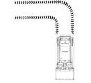
Welding And Grinding
Always clean the machine and attachment, disconnect the battery, and disconnect the wiring from the Bobcat controllers before welding. Cover rubber hoses, battery and all other flammable parts. Keep a fire extinguisher near the machine when welding.
Have good ventilation when grinding or welding painted parts. Wear dust mask when grinding painted parts. Toxic dust or gas can be produced.
Dust generated from repairing nonmetallic parts such as hoods, fenders or covers can be flammable or explosive. Repair such components in a well ventilated area away from open flames or sparks.
Fire Extinguishers
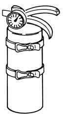
Know where fire extinguishers and first aid kits are located and how to use them. Inspect the fire extinguisher and service the fire extinguisher regularly. Obey the recommendations on the instructions plate.
SERIAL NUMBER LOCATIONS
Always use the serial number of the loader when requesting service information or when ordering parts. Early or later models (identification made by serial number) may use different parts, or it may be necessary to use a different procedure in doing a specific service operation.
Figure 1
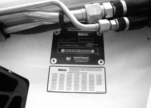
Loader Serial Number
The loader serial number plate is located on the outside of the loader frame [Figure 1]
Explanation of loader Serial Number:
Module 2. - Production Sequence (Series)
Module 1. - Model / Engine Combination
1. The four digit Model/Engine Combination Module number identifies the model number and engine combination.
2. The five digit Production Sequence Number identifies the order which the loader is produced.
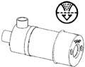
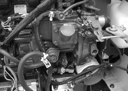
Engine Serial Number
Figure 2
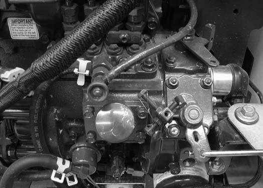
The engine serial number is located on the side of the engine [Figure 2]
P-45263
P-48387
The delivery report must be filled out by the dealer and signed by the owner or operator when the Bobcat loader is delivered. An explanation of the form must be given to the owner. Make sure it is filled out completely [Figure 3]
B-16315
OPERATOR SEAT with SEAT BELT & SEAT BAR
CYLINDERS
GRAB HANDLES
BUCKET STEPS
FRONT LIGHTS
† BUCKET
◆ REAR AUXILIARY QUICK COUPLERS
REAR GRILL
FRONT AUXILIARY QUICK COUPLERS
DOOR
REAR LIGHT
● OPERATOR CAB (ROPS / FOPS)

◆ Optional or Field Accessory (Not Standard Equipment)
✽ TIRES - Tires shown may not be standard. The machine is factory equipped with standard tires. Other tires are available.
† Bucket - Several different buckets and other attachments are available for this machine.
● ROPS, FOPS - Roll Over Protective Structure, per SAE / ISO 3471, and Falling Object Protective Structure per ISO 3449, Level I. Level I I is available.
B-19877A
B-19876A
SAFETY AND MAINTENANCE
AIR CLEANER SERVICE .
Replacing Filter Elements .
BOB-TACH (HAND LEVER)
Inspection And Maintenance
BOB-TACH (POWER). .
Inspection And Maintenance
ENGINE COOLING SYSTEM.
Checking Level
Cleaning.
Removing And Replacing Coolant.
ENGINE LUBRICATION SYSTEM .
Checking And Adding Engine Oil.
Engine Oil Chart.
Removing And Replacing Oil And Filter.
FINAL DRIVE TRANSMISSION (CHAINCASE).
Checking And Adding Oil.
Removing And Replacing Oil.
FUEL SYSTEM. .
Biodiesel Blend Fuel
Filling The Fuel Tank
Fuel Filter.
Fuel Specifications.
Removing Air From The Fuel System
HYDRAULIC / HYDROSTATIC SYSTEM.
Breather Cap
Checking And Adding Fluid
Hydraulic / Hydrostatic Fluid Chart
Removing And Replacing Hydraulic Fluid
Removing And Replacing Hydraulic / Hydrostatic Filter
10-80-1
10-80-1
10-140-1
10-140-1
10-141-1
10-141-1
10-90-1
10-90-2
10-90-1
10-90-3
10-110-1
10-110-1
10-110-1
10-110-2
10-130-1
10-130-1
10-130-1
10-100-1
10-100-1
10-100-2
10-100-3
10-100-1
10-100-3
10-120-1
10-120-7
10-120-1
10-120-1
10-120-2
10-120-2
Removing And Replacing Hydraulic Case Drain Filters (Single Speed Loaders).
10-120-3
Removing And Replacing Hydraulic Case Drain Filters (Two-Speed Loaders).
Removing And Replacing Hydraulic Charge Filter.
LIFT ARM SUPPORT DEVICE.
Installing.
Removing.
LIFTING AND BLOCKING THE LOADER
Procedure
Continued On Next Page
10-120-4
10-120-6
10-20-1
10-20-1
10-20-2
10-10-1
10-10-1
SAFETY AND MAINTENANCE (CONT’D)
LOADER STORAGE AND RETURN TO SERVICE
Return to Service. .
Storage.
LUBRICATING THE LOADER
Lubrication Locations.
OPERATOR CAB
Description.
Cab Door Sensor.
Lowering .
Raising.
Special Applications Kit
. 10-190-1
10-190-1
10-190-1
10-150-1
10-150-1
10-30-1
10-30-1
10-30-4
10-30-3
10-30-2
10-30-4
Special Applications Kit Inspection And Maintenance. . . . 10-30-4
PIVOT PINS
Inspection And Maintenance
REMOTE START TOOL KIT -MEL1563
Remote Start Procedure
Remote Start Tool - MEL1563
Service Tool Harness Communicator - MEL1566
Service Tool Harness Control - MEL1565
10-180-1
10-180-1
10-60-1
10-60-4
10-60-1
10-60-3
10-60-2
REMOTE START TOOL (SERVICE TOOL) KIT - 6689779 . . 10-61-1
Computer Service Tool Harness - 6689746.
Description.
Loader Service Tool Harness - 6689747
Remote Start Procedure
Remote Start Tool (Service Tool) - 6689778
SERVICE SCHEDULE
Chart
SPARK ARRESTOR MUFFLER
Cleaning Procedure.
10-61-4
10-61-1
10-61-3
10-60-5
10-61-2
10-70-1
10-70-1
10-170-1
10-170-1
STOPPING THE ENGINE AND LEAVING THE LOADER . . 10-200-1
Emergency Exit
Procedure
TIRE MAINTENANCE.
Mounting
Rotating
Wheel Nuts
10-200-2
10-200-1
10-160-1
10-160-1
10-160-1
10-160-1
Continued On Next Page
SAFETY AND MAINTENANCE (CONT’D)
TOWING THE LOADER
Procedure
TRANSPORTING THE LOADER ON A TRAILER
Fastening. .
Loading And Unloading
10-50-1
10-50-1
10-40-1
10-40-1
10-40-1
TIGHTEN ALL HARDWARE PER SIZE TO GRADE 5 TORQUE (SEE STANDARD TORQUE SPECIFICATIONS FOR BOLTS, SPEC SECTION) UNLESS OTHERWISE SPECIFIED.
LIFTING AND BLOCKING THE LOADER
Figure 10-10-1

WARNING
Instructions are necessary before operating or servicing machine. Read and understand the Operation & Maintenance Manual, Operator’s Handbook and signs (decals) on machine. Follow warnings and instructions in the manuals when making repairs, adjustments or servicing. Check for correct function after adjustments, repairs or service. Untrained operators and failure to follow instructions can cause injury or death.
W-2003-0903
Figure 10-10-2
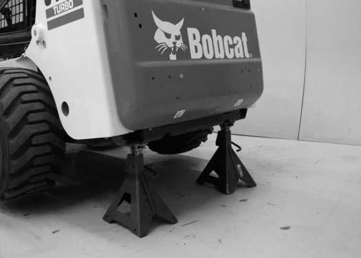
Put a floor jack under the rear of the loader.
Lift the rear of the loader and install jackstands [Figure 10-10-2]
Figure 10-10-3
Procedure
Always park the loader on a level surface.
WARNING
Put jackstands under the front axles and rear corners of the frame before running the engine for service. Failure to use jackstands can allow the machine to fall or move and cause injury or death.
W-2017-0286
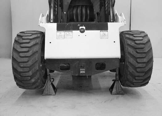
Put the floor jack under the front of the loader.
Lift the front of the loader and put jackstands under the axle tubes [Figure 10-10-3]
NOTE:Make sure the jackstands do not touch the tires. Make sure tires clear the floor and any obstacles.
B-7023A
P-45481
P-45482
Installing
Never work on a machine with the lift arms up unless the lift arms are secured by an approved lift arm support device. Failure to use an approved lift arm support device can allow the lift arms or attachment to fall and cause injury or death.
Service lift arm support device if damaged or if parts are missing. Using a damaged lift arm support or with missing parts can cause lift arms to drop causing injury or death.
W-2572-0407
Remove attachment from the loader. See BOB-TACH (HAND LEVER) on Page 50-40-1. OR See BOB-TACH (POWER-OPTION) on Page 50-41-1.
Figure 10-20-1
Figure 10-20-2
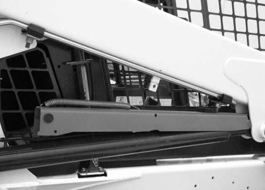
Lower the lift arm support device to the top of the lift cylinder. Hook the free end of the spring (Item 1) [Figure 10-20-2] to the lift arm support device so there will be no interference with the support device engagement.
Sit in the operator’s seat, fasten the seat belt and lower the seat bar. Start the engine.
Figure 10-20-3
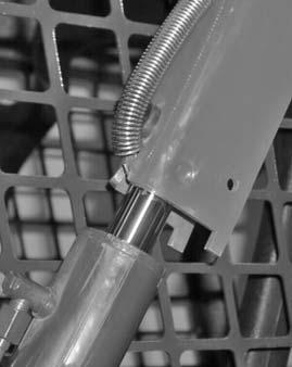
Raise the lift arms until the lift arm support device drops onto the lift cylinder rod (Item 1) [Figure 10-20-3]

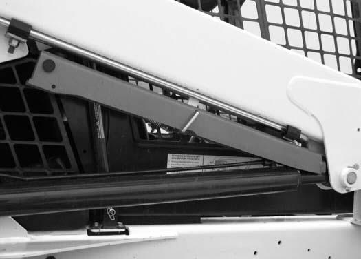
Put jackstands under the rear corners of the loader frame (Inset) [Figure 10-20-1]
Disconnect the spring (Item 1) from the lift arm support device retaining pin. Support the lift arm support device (Item 2) with your hand and remove the retaining pin (Item 3) [Figure 10-20-1]
Lower the lift arms slowly until the support device is held between the lift arm and the lift cylinder. Stop the engine. Raise the seat bar and move both pedals until both pedals lock.
Install pin (Item 2) [Figure 10-20-3] into the rear of the lift arm support device below the cylinder rod.
Removing
Remove the pin from the lift arm support device.
Figure 10-20-4
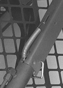
Connect the spring (Item 1) [Figure 10-20-4] from the lift arm support device to the bracket below the lift arms.
Sit in the operator’s seat fasten the seat belt and lower the seat bar.
Start the engine.
Figure 10-20-5
Raise the lift arms a small amount. The spring will lift the support device off the lift cylinder rod. Lower the lift arms. Stop the engine.
Raise the seat bar, disconnect the seat belt, move pedals until both pedals lock and exit the cab.
Disconnect the spring from the bracket.
Raise the support device into storage position and insert pin (Item 1) [Figure 10-20-5] through lift arm support device and bracket. Connect the spring to the pin.
Remove the jackstands.
P-45251
Description
The Bobcat Loader has an operator cab (ROPS and FOPS) as standard equipment to protect the operator from rollover and falling objects. Check with your dealer if the operator cab has been damaged. The seat belt must be worn for rollover protection.
ROPS / FOPS - Roll Over protective Structure per ISO 3471, and Falling Object Protective Structure per SAE J1043 and ISO 3449, Level I. Level II is available.
Level I - Protection from falling bricks, small concrete blocks, and hand tools encountered in operations such as highway maintenance, landscaping, and other construction sites.
Level II - Protection from falling trees, rocks: for machines involved in site clearing, overhead demolition or forestry.
WARNING
Never modify operator cab by welding, grinding, drilling holes or adding attachments unless instructed to do so by Bobcat Company. Changes to the cab can cause loss of operator protection from rollover and falling objects, and result in injury or death.
W-2069-0200
OPERATOR CAB (CONT’D)
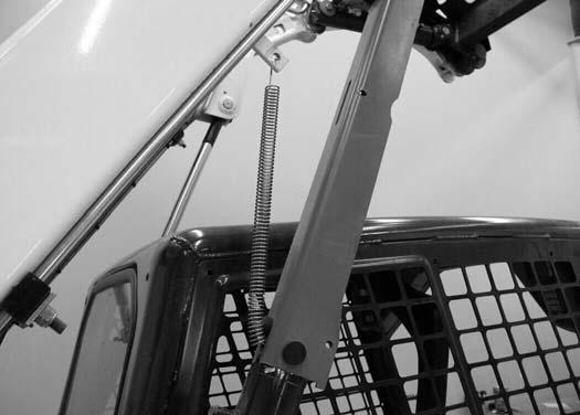
Raising
Always stop the engine before raising or lowering the cab.
Stop the loader on a level surface. Lower the lift arms. If the lift arms must be up while raising the operator cab, install the lift arm support device. (See LIFT ARM SUPPORT DEVICE on Page 10-20-1.)
Figure 10-30-1

Install jackstands under the rear of the loader frame [Figure 10-30-1]
Figure 10-30-2

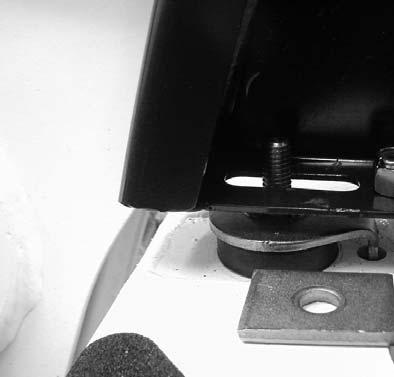
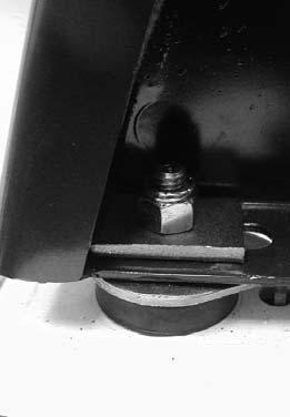
Remove the nuts and plates [Figure 10-30-2] (both sides) at the front corners of the cab.

NOTE:On Advanced Control System (ACS) equipped machines, the steering levers could contact the cab frame while raising or lowering the operator cab. The engine MUST be stopped before raising or lowering the cab.
10-30-3
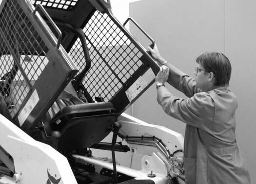
Lift on the grab handles and bottom of the operator cab [Figure 10-30-3] slowly until the cab is all the way up and the latching mechanism engages.
Figure
P-43747 P-31289
P-45261
OPERATOR CAB (CONT’D)
Lowering
Always stop the engine before raising or lowering the cab.
NOTE:Always use the grab handles to lower the cab.
Figure 10-30-4
PINCH POINT CAN CAUSE INJURY
Remove your hand from the latching mechanism when the cab is past the latch stop.

Figure 10-30-5
Pull down on the bottom of the operator cab until it stops at the latching mechanism [Figure 10-30-4].
NOTE: The weight of the cab increases when equipped with options and accessories such cab door, heater, air conditioning, etc. In these cases, the cab may need to be raised slightly from the latch to be able to release the latch.

NOTE:On Advanced Control System (ACS) equipped machines, the steering levers could contact the cab frame while raising or lowering the operator cab. The engine MUST be stopped before raising or lowering the cab.
Support the cab and release the latching mechanism (Inset) [Figure 10-30-4]. Remove your hand from latching mechanism when the cab is past the latch stop. Use both hands to lower the cab all the way.
Install the plates and nuts (both sides) [Figure 10-30-5] Tighten the nuts to 40-45 ft.-lb. (54-61 N•m) torque.
P-31289
P-31288
OPERATOR CAB (CONT’D)
Cab Door Sensor
This machine may be equipped with a Cab Door Sensor.
Figure 10-30-6

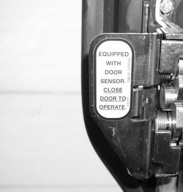
The cab door (option) has a sensor (Item 1) [Figure 1030-6] installed which deactivates the lift and tilt valves when the door is open.
CLOSE DOOR TO OPERATE (Item 2) [Figure 10-30-6] lift and tilt valves.
The LIFT & TILT VALVE light (Item 3) [Figure 10-30-6] will be ON when the door is closed and the PRESS TO OPERATE LOADER BUTTON is pressed.
Special Applications Kit
Figure 10-30-7
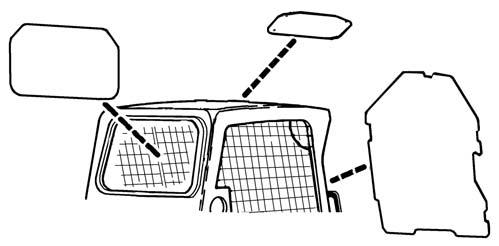
Available for special applications to restrict material from entering cab openings. Kit includes 1/2 inch polycarbonate front door, top and rear windows. [Figure 10-30-7]
See your Bobcat dealer for availability.
Special Applications Kit Inspection And Maintenance
•Inspect for cracks or damage. Replace if required.
•Pre-rinse with water to remove gritty materials.
•Wash with a mild household detergent and warm water.
•Use a sponge or soft cloth. Rinse well with water and dry with a clean soft cloth or rubber squeegee.
•Do not use abrasive or highly alkaline cleaners.
•Do not operate windshield wipers on a dry surface.
•Do not clean with metal blades or scrapers.
B-25286A
Loading And Unloading WARNING
AVOID SERIOUS INJURY OR DEATH
Adequately designed ramps of sufficient strength are needed to support the weight of the machine when loading onto a transport vehicle. Wood ramps can break and cause personal injury.
W-2058-0807
Be sure the transport and towing vehicles are of adequate size and capacity for weight of loader. (See Performance on Page SPEC-10-2) and (See Performance on Page SPEC-11-2)
Figure 10-40-1
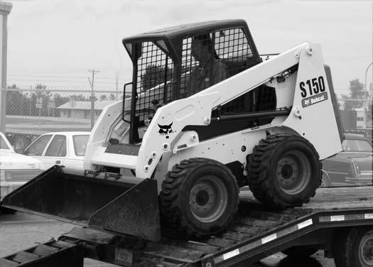
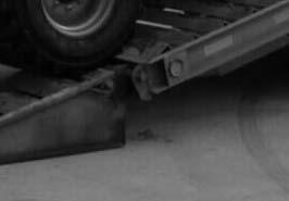

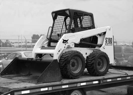
A loader with an empty bucket or no attachment must be loaded backward onto the transport vehicle [Figure 1040-1]
The rear of the trailer must be blocked or supported (Item 1) [Figure 10-40-1] when loading or unloading the loader to prevent the front end of the trailer from raising up.
Fastening
Figure 10-40-2

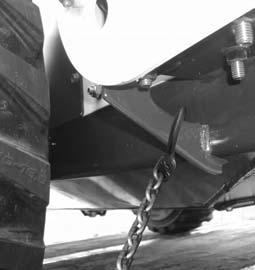

Use the following procedure to fasten the Bobcat Loader to the transport vehicle to prevent the loader from moving during sudden stops or when going up or down slopes [Figure 10-40-2]
•Lower the bucket or attachment to the floor.
•Stop the engine.
•Engage the parking brake.
•Install chains at the front and rear loader tie down positions [Figure 10-40-2]
•Fasten each end of the chain to the transport vehicle.
P-45215C
P-43631
P-45218C
P-45989
Alternate Front Tie-Down
P-31228
P-73276
Procedure
Because of the design of the loader, there is not a recommended towing procedure.
•The loader can be lifted onto a transport vehicle.
•The loader can be skidded a short distance to move for service (EXAMPLE: Move onto a transport vehicle.) without damage to the hydrostatic system. (The tires/tracks will not turn.) There might be slight wear to the tires/tracks when the loader is skidded.
The towing chain (or cable) must be rated at 1 & 1/2 times the weight of the loader. (See Performance on Page SPEC-10-2.) and (See Performance on Page SPEC-11-2.)
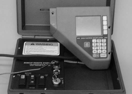
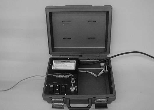
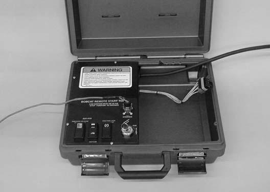
Remote Start Tool - MEL1563
Tools that will be needed to complete the following steps are:
MEL1563 - Remote Start Tool
MEL1565 - Service Tool Harness Control
MEL1566 - Service Tool Harness Communicator (Computer Interface)
10-60-1
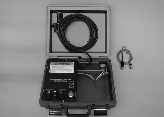
The remote start tool (Item 1) [Figure 10-60-1] is required when the service technician is checking the hydraulic/hydrostatic system or adjusting the steering linkage.
Figure 10-60-2
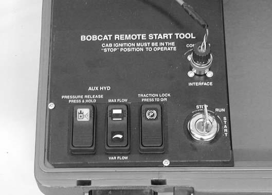
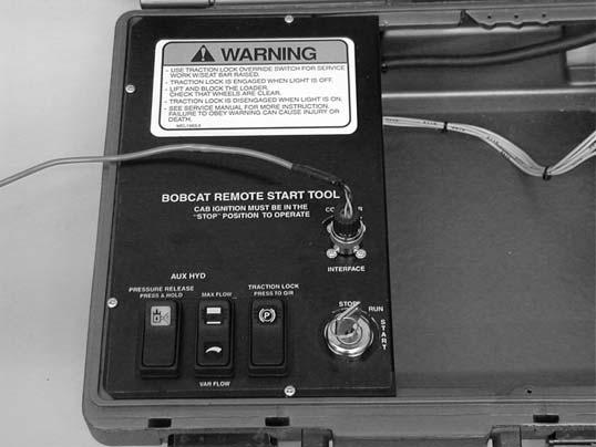
The traction lock switch (Item 1) [Figure 10-60-2] is used to turn traction lock ON or OFF. Push the switch to the override postion. The switch will illuminate to indicate traction lock OVERRIDE, in this position the wheels are able to turn.
The maximum flow/variable flow switch (Item 2) [Figure 10-60-2] is used to activate the auxiliary hydraulics. Pressing the switch once will activate maximum flow. Pressing the switch again will activate variable flow. The switch will illuminate to indicate which flow rate is active. Pressing the switch a third time will turn the flow OFF. The switch is used when checking pressures and flow rate.
The auxiliary pressure release (Item 3) [Figure 10-60-2] is used to release hydraulic pressure to the front and/or rear auxiliary couplers. To release pressure; push and hold the switch for a few seconds.
NOTE:With the engine running; pushing and holding the pressure release switch will cause the engine to stop. To relieve the pressure; press the switch until the engine stops.
Figure
P16114
P16117
REMOTE
START TOOL-MEL1563 (CONT'D)
Remote Start Tool - MEL1563 (Cont’d)
Figure 10-60-3
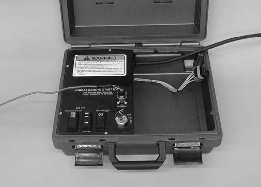
Figure 10-60-4
The 10-pin rectangular connector (Item 1) [Figure 10-603] is used to update software in the Deluxe Instrumentation Panel (Item 1) [Figure 10-60-4].
NOTE: The Service PC must be connected to the remote start tool to update the deluxe panel software.
The panel must be removed from inside the operator cab and plugged into this connector [Figure 10-60-3].
Service Tool Harness Control - MEL1565
Figure 10-60-5
The service tool harness control (Item 1) [Figure 10-605] is used to connect the remote start tool (Item 2) [Figure 10-60-5] to the electrical system on the loader.
Figure 10-60-6
Remove the plug (Item 1) [Figure 10-60-6] from the loader harness connector.
Connect the service tool harness control to the loader harness connector.
Service Tool Harness Control - MEL1565 (Cont’d)
Figure 10-60-7
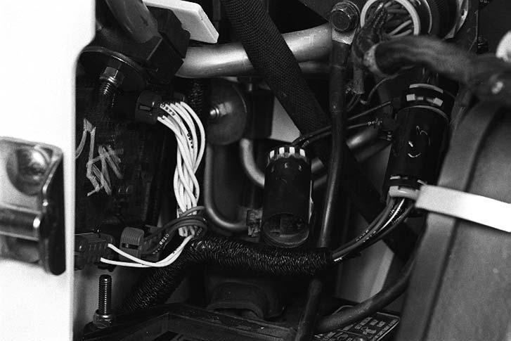
Loaders equipped with an attachment harness (Item 1) [Figure 10-60-7] must disconnect the attachment harness from the loader harness (Item 2) [Figure 10-607]
Connect the service tool harness to the ACD connector and the loader harness connector.
NOTE:To monitor, diagnose or load new software the Service PC must be connected to the Remote Start Tool Switch.
Service Tool Harness Communicator - MEL1566
Figure 10-60-8
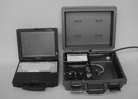
The service tool harness communicator (Item 1) [Figure 10-60-8] is required to connect remote start tool to the Service PC (Item 2) [Figure 10-60-8]
Remote Start Procedure
The tool listed will be needed to do the following procedure:
MEL1563: Remote Start Tool Kit
Figure 10-60-9
The remote start tool (Item 1) [Figure 10-60-9] is required when the operator cab is in the raised position for service and the service technician needs to turn the key switch on or start the engine. Example: adjusting the steering linkage.
Lift and block the loader.
Raise the lift arms (if required by the procedure) and install an approved lift arm support device.
Raise the operator cab (if required by the procedure).
Open the rear door of the loader.
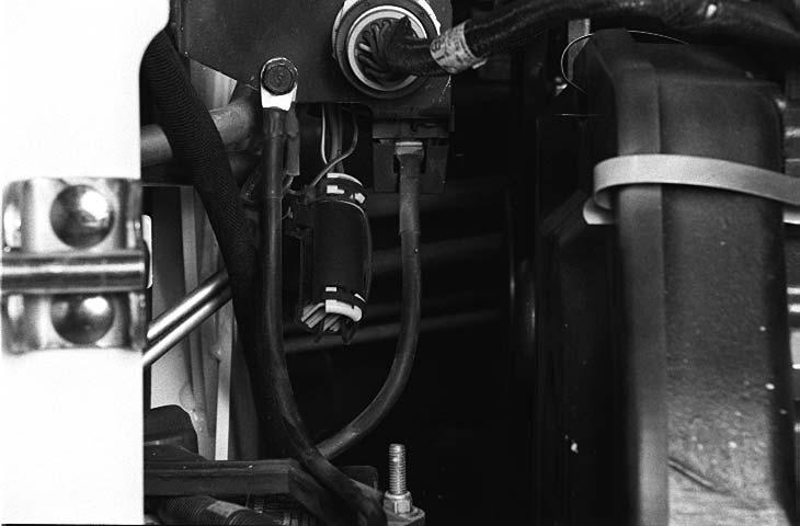
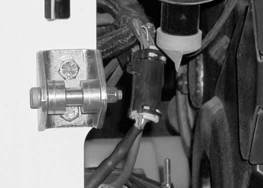
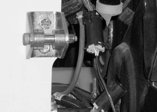
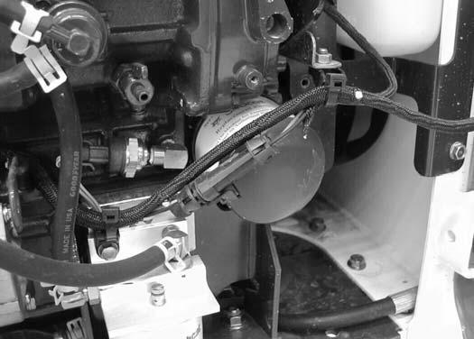
Figure 10-60-10
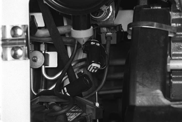
Figure 10-60-11
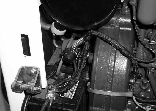
Remove the plug (Item 1) [Figure 10-60-10] or disconnect the attachment control harness (Item 1) [Figure 10-60-11] if connected.
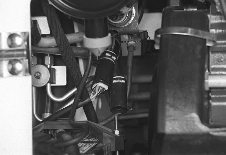
Figure 10-60-12
Connect the remote start tool to the engine harness connector [Figure 10-60-12]
NOTE:The key switch on the right-hand side operator panel must be in the off position or the Remote Start Kit will not operate.
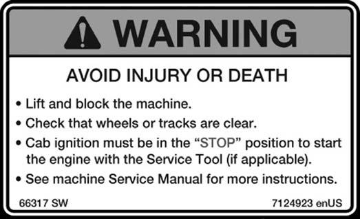
WARNING
AVOID INJURY OR DEATH
With the 7-pin connector plugged into the loader and the Remote Start Key Switch in the OFF position, the loader can still be started from the operator panel inside the cab. Placing the key switch of the remote start tool in the run position disconnects the operator panel key switch from the start circuit. If the service technician will be working in the engine area it is important to remove the operator panel keys.
W-2357-0899
Remote Start Procedure (Cont'd)
Figure 10-60-13
The remote start tool (Item 1) [Figure 10-60-13] has three rocker switches.
Figure 10-60-14
The traction lock switch (Item 1) [Figure 10-60-14] is used to turn traction lock on or off. Push the switch to the override position. The switch will illuminate to indicate traction lock OVERRIDE, in this position the wheels are able to turn.
The maximum flow/variable flow switch (Item 2) [Figure 10-60-14] is used to activate the auxiliary hydraulics. Pressing the switch once will activate variable flow. Pressing the switch again will activate maximum flow. The switch will illuminate to indicate which flow rate is active. Pressing the switch a third time will turn the flow OFF. The switch is used when checking pressures and flow rate.
The auxiliary pressure release (Item 3) [Figure 10-60-14] is used to release hydraulic pressure to the front and/or rear auxiliary couplers. To release pressure; push and hold the switch for three seconds.
NOTE:With the engine running; pushing and holding the pressure release switch will cause the engine to stop in three seconds. To relieve the pressure; continue to press the switch after the engine has stopped.
P16116
P16118
Remote Start Procedure (Cont'd)
NOTE:With the engine running; pushing and holding the pressure release switch will cause the engine to stop in three seconds. To relieve the pressure at the rear or right hand auxiliary, (If so equipped.) continue to hold the switch for three seconds after the engine has stopped.
Figure 10-60-15
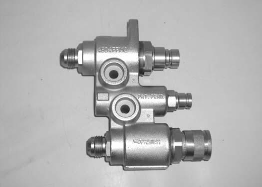
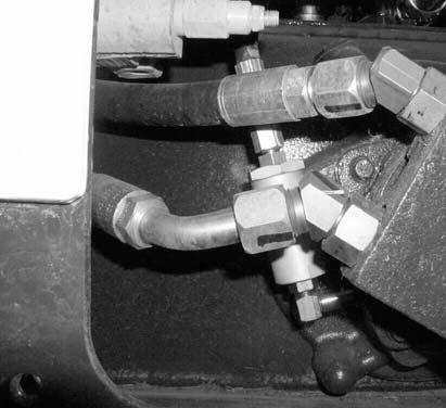
Push the couplers on the front auxiliary block toward the block and hold for five seconds to release the front auxiliary pressure [Figure 10-60-15] P-34661
Description
The Remote Start Tool (Service Tool) Kit is a replacement tool for MEL 1563 Remote Start Tool and MEL 1400BBOSS® Diagnostic Tool.
The Remote Start Tool (Service Tool) Kit, P/N 6689779, can be used to service older loaders with the BOSS® system using the supplied BOSS® Service Tool Harness P/N 6689745.
The Remote Start Tool (Service Tool) Kit, P/N 6689779, can be used to service newer loaders using the supplied harness P/N 6689747.
A computer can be connected to the Remote Start Tool (Service Tool) for diagnostics and software updates using the computer harness P/N 6689746 in conjunction with the loader harness.
Remote Start Tool (Service Tool) - 6689778
Tools that will be needed to complete the following steps are:
Order from Bobcat Parts P/N: 6689779 - Remote Start Tool (Service Tool) Kit
Kit Includes:
6689778 - Remote Start Tool (Service Tool)
6689747 - Loader Service Tool Harness
6689746 - Computer Service Tool Harness
6689745 - BOSS® Service Tool Harness
10-61-16

The remote start tool (Item 1) [Figure 10-61-16] is required when the service technician is checking the hydraulic / hydrostatic system or adjusting the steering linkage.
Figure 10-61-17

The Remote Start Tool (Service Tool) (Item 1) [Figure 1061-17] has five buttons.
The STOP button (Item 2) [Figure 10-61-17] is used to stop the Remote Start Tool (Service Tool) from communicating and stop the loader engine.
The RUN button (Item 3) [Figure 10-61-17] is used to turn the Remote Start Tool (Service Tool) on and activates the loader ignition power. The button will illuminate to indicate the service tool is active.
The START button (Item 4) [Figure 10-61-17] is used to start the loader engine.
The traction lock button (Item 5) [Figure 10-61-17] is used to turn traction lock ON or OFF. Push the button and the button will illuminate indicating the traction lock is disabled in which the wheels or tracks are able to turn.
Loader
S/N: xxxx60000 & Below
The auxiliary button (Item 6) [Figure 10-61-17] is used to activate the auxiliary hydraulics. The button will illuminate to indicate the auxiliary hydraulics are active. Pressing the button once will activate maximum flow. Pressing the button again will activate variable flow. Pressing the button a third time will turn the flow OFF. The button is used when checking pressures and flow rate.
Loader
S/N: xxxx60001 & Above
The auxiliary button (Item 6) [Figure 10-61-17] is used to activate the auxiliary hydraulics. The button will illuminate to indicate the auxiliary hydraulics are active. Pressing the button a second time will turn the flow OFF. The button is used when checking pressures and flow rate.
Figure
Loader Service Tool Harness - 6689747
Figure 10-61-18
The loader service tool harness (Item 1) [Figure 10-6118] is used to connect the remote start tool (service tool) (Item 2) [Figure 10-61-18] to the electrical system on the loader.
Figure 10-61-19
Loaders without an attachment control harness, remove the loader harness cap (Item 1) [Figure 10-61-19] and connect the Loader Service Tool Harness from the Remote Start Tool (Service Tool).
Figure 10-61-20
Loaders with an attachment control harness (7 pin or 14 pin), the attachment harness (Item 1) must be disconnected from the loader harness (Item 2) [Figure 10-61-20]
When the remote start procedure is completed, replace the loader connector cap (Item 1) [Figure 10-61-19] or reconnect the attachment control harness to the loader harness [Figure 10-61-20]
REMOTE START TOOL (SERVICE TOOL) KIT6689779 (CONT'D)
Loader Service Tool Harness - 6689747 (Cont’d)
Figure 10-61-21
NOTE:The Remote Start Tool (Service Tool) connection harness has two connectors (Item 1) and (Item 3). The main connector (Item 1) [Figure 10-61-21] is always used for connection to the loader harness.
The second connector (Item 3) [Figure 10-6121] is used for attachment ACD upgrades or attachment operational diagnostics only. This connector has a cap attached to it to prevent damage or corrosion when not in use.
Connect the Remote Start Tool (Service Tool) connector (Item 1) to the loader harness connector (Item 2) and the other Remote Start Tool (Service Tool) connector to the ACD harness connector (Item 3) [Figure 10-61-21]
NOTE:The right instrument panel (Key Switch or Keyless) must be in the off position or the Remote Start Tool (Service Tool) will not operate.
Computer Service Tool Harness - 6689746
Figure 10-61-22

The computer service tool harness (Item 1) [Figure 1061-22] is required to connect remote start tool (service tool) to the Service PC (Item 2) [Figure 10-61-22]
Remote Start Procedure
AVOID INJURY OR DEATH
With the 7-pin connector plugged into the loader and Remote Start Tool RUN button is not illuminated, the loader can still be started from the operator panel inside the cab.
Pressing the RUN button on the Remote Start Tool disconnects the operator panel from the start circuit. If the service technician will be working in the engine area it is important to remove the operator panel key or lock the keypad with a unique password.
W-2647-0707
The tool listed will be needed to do the following procedure:
6689779: Remote Start Tool (Service Tool) Kit
Figure 10-61-23
The Remote Start Tool (Service Tool) (Item 1) [Figure 1061-23] is required when the operator cab is in the raised position for service and the service technician needs to turn on the loader or start the engine. Example: adjusting the steering linkage.
Lift and block the loader.
Raise the lift arms (if required by the procedure) and install an approved lift arm support device.
Raise the operator cab (if required by the procedure).
Open the rear door of the loader.
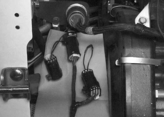
Figure 10-61-24
Loaders without an attachment control harness, remove the loader harness cap (Item 1) [Figure 10-61-24] and connect the Loader Service Tool Harness from the Remote Start Tool (Service Tool).
Figure 10-61-25
Loaders with an attachment control harness (7 pin or 14 pin), the attachment harness (Item 1) must be disconnected from the loader harness (Item 2) [Figure 10-61-25]
When the remote start procedure is completed, replace the loader connector cap (Item 1) [Figure 10-61-25] or reconnect the attachment control harness to the loader harness [Figure 10-61-25].
P-76451
P-76452
Remote Start Procedure (Cont'd)
Figure 10-61-26
NOTE:The Remote Start Tool (Service Tool) connection harness has two connectors (Item 1) and (Item 3). The main connector (Item 1) [Figure 10-61-26] is always used for connection to the loader harness.
The second connector (Item 3) [Figure 10-6126] is used for attachment ACD upgrades or attachment operational diagnostics only. This connector has a cap attached to it to prevent damage or corrosion when not in use.
Connect the Remote Start Tool (Service Tool) connector (Item 1) to the loader harness connector (Item 2) and the other Remote Start Tool (Service Tool) connector to the ACD harness connector (Item 3) [Figure 10-61-26]
NOTE:The right instrument panel (Key Switch or Keyless) must be in the off position or the Remote Start Tool (Service Tool) will not operate.
Figure 10-61-27
The Remote Start Tool (Service Tool) (Item 1) [Figure 1061-27] has five buttons.
The STOP button (Item 2) [Figure 10-61-27] is used to stop the Remote Start Tool (Service Tool) from communicating and stop the loader engine.
The RUN button (Item 3) [Figure 10-61-27] is used to turn the Remote Start Tool (Service Tool) on and activates the loader ignition power. The button will illuminate to indicate the service tool is active.
The START button (Item 4) [Figure 10-61-27] is used to start the loader engine.
The traction lock button (Item 5) [Figure 10-61-27] is used to turn traction lock ON or OFF. Push the button and the button will illuminate indicating the traction lock is disabled in which the wheels or tracks are able to turn.
Loader S/N: xxxx60000 & Below
The auxiliary button (Item 6) [Figure 10-61-27] is used to activate the auxiliary hydraulics. The button will illuminate to indicate the auxiliary hydraulics are active. Pressing the button once will activate maximum flow. Pressing the button again will activate variable flow. Pressing the button a third time will turn the flow OFF. The button is used when checking pressures and flow rate.
Loader S/N: xxxx60001 & Above
The auxiliary button (Item 6) [Figure 10-61-27] is used to activate the auxiliary hydraulics. The button will illuminate to indicate the auxiliary hydraulics are active. Pressing the button a second time will turn the flow OFF. The button is used when checking pressures and flow rate.
Remote Start Procedure (Cont'd)
Figure 10-61-28

The gear icon with the left facing arrows (Item 1) [Figure 10-61-28] will illuminate and blink when the RUN key is pressed and the loader is communicating with the service tool.
The computer icon with the right facing arrows (Item 2) [Figure 10-61-28] will illuminate and blink when the Remote Start Tool (Service Tool) is transmitting data to and from the computer.
Loader S/N: xxxx60000 & Below
NOTE:To relieve the pressure at the rear or secondary front auxiliary, (if equipped) press and hold the AUXILIARY PRESSURE RELEASE button on the left instrument panel for three seconds after the engine has stopped.
Loader S/N: xxxx60001 & Above
NOTE:To relieve the pressure at the rear or secondary front auxiliary, (if equipped) press the RUN button on the remote start tool. Then press the auxiliary (AUX) hydraulics button on the remote start tool and move the AUXILIARY Hydraulic Switch on the to the right and left several times.
10-61-29
Push the couplers on the front auxiliary block toward the block and hold for five seconds to release the front auxiliary pressure [Figure 10-61-29]
Figure
P-34661
SERVICE SCHEDULE
Chart
Maintenance work must be done at regular intervals. Failure to do so will result in excessive wear and early failures. The service schedule is a guide for correct maintenance of the Bobcat Loader.
WARNING
Instructions are necessary before operating or servicing machine. Read and understand the Operation & Maintenance Manual, Operator’s Handbook and signs (decals) on machine. Follow warnings and instructions in the manuals when making repairs, adjustments or servicing. Check for correct function after adjustments, repairs or service. Untrained operators and failure to follow instructions can cause injury or death. W-2003-0903
SERVICE SCHEDULE
ITEMSERVICE REQUIRED
Engine OilCheck the oil level and add as needed. Do not overfill.
Engine Air Filter and Air SystemCheck display panel. Service only when required. Check for leaks and damaged components.
Engine Cooling SystemClean debris from oil cooler, radiator and grill. Check coolant level COLD and add premixed coolant as needed.
Fuel FilterRemove the trapped water.
Lift Arms, Cylinders, Bob-Tach Pivot Pins and Wedges
Lubricate with multi-purpose lithium based grease.
TiresCheck for damaged tires and correct air pressure. Inflate to MAXIMUM pressure shown on the sidewall of the tire.
Seat Bar, Control Interlocks, Seat Belt, Seat Belt Retractors
Bobcat Interlock Control Systems (BICS)
Check the condition of seat belt. Clean or replace seat belt retractors as needed. Check the seat bar and control interlocks for correct operation. Clean dirt and debris from moving parts.
Check for correct function. Lift and Tilt functions MUST NOT operate with seat bar raised. See details in this Manual.
Safety Signs and Safety TreadsCheck for damaged signs (decals) and safety treads. Replace any signs or safety treads that are damaged or worn.
Operator CabCheck the fastening bolts, washers and nuts. Check the condition of the cab.
Indicators and LightsCheck for correct operation of all indicators and lights.
Heater and A/C Filters (If Equipped)
Hydraulic Fluid, Hoses and Tubelines
Clean or replace filters as needed.
Check fluid level and add as needed. Check for damage and leaks. Repair or replace as needed.
Final Drive Trans. (Chaincase), Check fluid level and add as needed.
Parking Brake, Foot Pedals, Hand Controls and Steering Levers or Joysticks
Check for correct operation. Repair or adjust as needed.
Wheel NutsCheck for loose wheel nuts and tighten to correct torque. (See TIRE MAINTENANCE in this manual.)
Spark Arrestor MufflerClean the spark chamber.
BatteryCheck cables, connections and electrolyte level. Add distilled water as needed.
Steering Lever PivotsGrease fittings.
Fuel FilterReplace filter element.
Engine / Hydro. Drive BeltCheck for wear or damage. Check idler arm stop.
Drive Belts (Alternator, air conditioner, water pump)
Bobcat Interlock Control System (BICS)
Hydraulic / Hydrostatic Filter, Charge Filter, Reservoir Breather
Check condition and tension. Adjust or replace as needed.
Check the function of the lift arm bypass control.
Replace the hydraulic / hydrostatic filter, charge filter, and the reservoir breather.
Engine Oil and FilterReplace oil and filter.
Final Drive Trans. (Chaincase)Replace the fluid.
Hydraulic ReservoirReplace the fluid.
Case Drain FiltersReplace the filters.
Engine ValvesAdjust the engine valves.
CoolantReplace the coolantEvery
■ Or every 12 months.
▲ Perform at first 50 hours, then as scheduled.
❏ Check every 8 - 10 hours for the first 24 hours, then at 50 hour intervals.
● Replace the hydraulic / hydrostatic filter element after the first 50 hours, then when the transmission warning light comes ON while operating or as scheduled.
✶ Change oil and filter every 250 hours when operating under severe conditions.
❍ Perform at first 500 hours, then as scheduled.
AIR CLEANER SERVICE
Replacing Filter Elements
Figure 10-80-1

It is important to change the air filter element only when the Air Cleaner Icon in the right panel is ON (Item 1) [Figure 10-80-1] and you hear three beeps from the alarm.
Replace the inner filter every third time the outer filter is replaced or as indicated.
Figure 10-80-2
Press and hold the LIGHT Button (Item 1) [Figure 10-802] for two seconds.
If the filter element needs replacement, the CODE [0117] (Air Filter Plugged) will show in the HOURMETER / CODE DISPLAY (Item 2) [Figure 10-80-2]
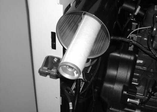
Outer Filter
Figure 10-80-3
Remove the wing nut and remove the dust cover (Item 1) [Figure 10-80-3]
Figure 10-80-4

Remove the wing nut and pull the outer filter element (Item 1) [Figure 10-80-4] out and discard.
NOTE:Make sure all sealing surfaces are free of dirt and debris.
Install new filter. Push all the way in until it contacts the base of the housing. Install wing nut.
Install the dust cover and the wing nut [Figure 10-80-3].
Check the air intake hose and the air cleaner housing for damage. Make sure all connections are tight.
AIR CLEANER SERVICE (CONT’D)
Replacing Filter Elements (Cont’d)
Inner Filter
Only replace the inner filter element under the following conditions:
•Replace the inner filter element every third time the outer filter is replaced.
•After the outer element has been replaced, start the engine and run at full RPM. If the HOURMETER / CODE DISPLAY shows [01-17] (Air Filter Plugged), replace the inner filter element.
10-80-5
Remove the inner filter element (Item 1) [Figure 10-805].
NOTE:Make sure all sealing surfaces are free of dirt and debris.
Install the new inner element [Figure 10-80-5]
Install the outer element.
10-80-6
Install the dust cover and the wing nut [Figure 10-80-6]
Figure
Figure
P-31838
P-31836
ENGINE COOLING SYSTEM
Check the cooling system every day to prevent overheating, loss of performance or engine damage.
Cleaning
Open the rear door and remove the rear grill. (See Removal And Installation on Page 50-60-1.)
Figure 10-90-1
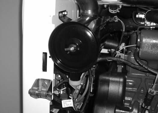
Use low air pressure or water pressure to clean the top of the air conditioning condenser (Item 1) [Figure 10-90-1], if equipped.
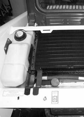
Figure 10-90-2
NOTE: Be careful when raising and lowering the air conditioning condenser so that the air conditioning condenser does not fall on the oil cooler and damage the fins.
Raise the air conditioning condenser (Item 1) and use low air pressure or water pressure to clean the top of the radiator (Item 2) [Figure 10-90-2].
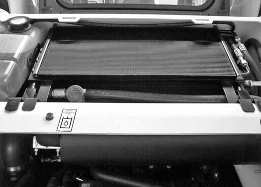
Figure 10-90-3
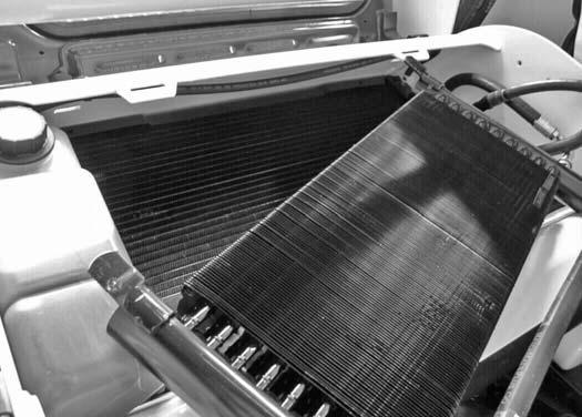
NOTE: Be careful when raising and lowering the oil cooler so that the oil cooler does not fall on the radiator and damage the fins.
Raise the oil cooler (Item 1) and use low air pressure or water pressure to clean the top of the radiator (Item 2) [Figure 10-90-3]
Lower the oil cooler.
Lower the air conditioning condenser, if equipped.
Check the cooling system for leaks.
Lower the rear grill and close the rear door.
P-76183
P-76182
ENGINE COOLING SYSTEM (CONT’D)
Checking Level
Open the rear door and raise the rear grill.
Figure 10-90-4
WARNING
AVOID INJURY OR DEATH

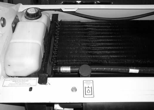
Remove the coolant fill cap (Item 1). Check the coolant level. The level markers are on the tank. Coolant must be at the bottom marker when the engine is cold; top marker when hot (Item 2) [Figure 10-90-4].
Close the rear door before operating the loader.
IMPORTANT
AVOID ENGINE DAMAGE
Always use the correct ratio of water to antifreeze.
Too much antifreeze reduces cooling system efficiency and may cause serious premature engine damage.
Too little antifreeze reduces the additives which protect the internal engine components; reduces the boiling point and freeze protection of the system.
Always add a premixed solution. Adding full strength concentrated coolant can cause serious premature engine damage. I-2124-0497
Wear safety glasses to prevent eye injury when any of the following conditions exist:
•When fluids are under pressure.
•Flying debris or loose material is present.
•Engine is running.
•Tools are being used.
W-2019-0907
ENGINE COOLING SYSTEM (CONT’D)
Removing And Replacing Coolant
Open the rear door and remove the rear grill.
Figure 10-90-5
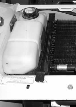
Remove the coolant fill cap (Item 1) [Figure 10-90-5]
Connect a hose to the engine block drain (Item 2) [Figure 10-90-5]. Open the drain valve and drain the coolant into a container. Close the drain valve.
Recycle or dispose of used coolant in an environmentally safe manner.
NOTE: The loader is factory filled with propylene glycol coolant (purple color). DO NOT mix propylene glycol with ethylene glycol.
Premix coolant (53% propylene glycol and 47% water) in a separate container. For correct capacity, (See Capacities on Page SPEC-4.) or (See Capacities on Page SPEC-4.)
One gallon and one pint of propylene glycol mixed with one gallon of water is the correct ratio (53%/47%) to provide -34°F (-37°C) freeze protection.
Fill the tank until it is at the lower marker on the tank.
Use a refractometer to check the condition of propylene glycol in the cooling system and replace the coolant fill cap.
NOTE:When installing the coolant fill cap, the cap must be tightened until it clicks.
Run the engine until it is at operating temperature. Stop the engine. Check the coolant level in the recovery tank when cool. Add coolant as needed.
Install the rear grill and close the rear door.
P-45490
P-45245
Fuel Specifications
Use only clean, high quality diesel fuel, Grade No. 2 or Grade No. 1.
The following is one suggested blending guideline which should prevent fuel gelling during cold temperatures:
TEMPERATURE F (C) NO. 2 NO. 1
+15° (9°)100%0%
Down to -20° (-29°)50%50%
Below -20° (-29°)0%100%
The following fuels may be used in this machine:
•Low Sulfur (500 ppm sulfur) Diesel Fuel.
•Ultra Low Sulfur (15 ppm sulfur) Diesel Fuel.
•Biodiesel Blend Fuel - Must contain no more than five percent biodiesel mixed with low sulfur or ultra low sulfur petroleum based diesel. This is commonly marketed as B5 blended diesel fuel. B5 blended diesel fuel must meet ASTM D975 (US Standard) or EN590 (EU Standard) specifications.
Biodiesel Blend Fuel
Biodiesel blend fuel has unique qualities that should be considered before using in this machine:
•Cold weather conditions can lead to plugged fuel system components and hard starting.
•Biodiesel blend fuel is an excellent medium for microbial growth and contamination which can cause corrosion and plugging of fuel system components.
•Use of biodiesel blend fuel may result in premature failure of fuel system components, such as plugged fuel filters and deteriorated fuel lines.
•Shorter maintenance intervals may be required, such as cleaning the fuel system and replacing fuel filters and fuel lines.
•Using biodiesel blended fuels containing more than five percent biodiesel can affect engine life and cause deterioration of hoses, tubelines, injectors, injector pump and seals.
Apply the following guidelines if biodiesel blend fuel is used:
•Ensure the fuel tank is as full as possible at all times to prevent moisture from collecting in the fuel tank.
•Ensure that the fuel tank cap is securely tightened.
•Biodiesel blend fuel can damage painted surfaces, remove all spilled fuel from painted surfaces immediately.
•Drain all water from the fuel filter daily before operating the machine.
•Do not exceed engine oil change interval. Extended oil change intervals can cause engine damage.
•Before vehicle storage; drain the fuel tank, refill with 100% petroleum diesel fuel, add fuel stabilizer and run the engine for at least 30 minutes.
NOTE:Biodiesel blend fuel does not have long term stability and should not be stored for more than three months.
Filling The Fuel Tank
WARNING
AVOID INJURY OR DEATH
Stop and cool the engine before adding fuel. NO SMOKING! Failure to obey warnings can cause an explosion or fire.
W-2063-0807
Figure 10-100-2
Open the rear door.
Figure 10-100-1
Remove the fuel fill cap (Item 1) [Figure 10-100-1]
Use a clean, approved safety container to add fuel of the correct specification. Add fuel only in an area that has free movement of air and no open flames or sparks. NO SMOKING! [Figure 10-100-2]
Install and tighten the fuel fill cap (Item 1) [Figure 10100-1]
WARNING
AVOID INJURY OR DEATH
Always clean up spilled fuel or oil. Keep heat, flames, sparks or lighted tobacco away from fuel and oil. Failure to use care around combustibles can cause explosion or fire which can result in injury or death.
W-2103-0807
FUEL SYSTEM (CONT’D)
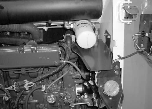
Fuel Filter
For the service interval for removing water from, or replacing the fuel filter (See SERVICE SCHEDULE on Page 10-70-1.)
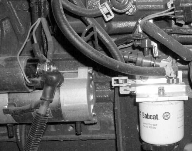
Figure 10-100-3
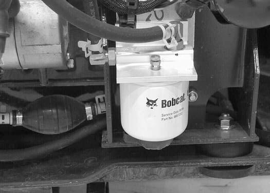
Removing Water
Loosen the drain (Item 1) [Figure 10-100-3] at the bottom of the filter element to remove water from the filter.
Replacing Element
Remove the filter element (Item 2) [Figure 10-100-3]
Clean the area around the filter housing. Put clean oil on the seal of the new filter element. Install the fuel filter, and hand tighten.
Remove air from the fuel system. (See Removing Air From The Fuel System below.)
Removing Air From The Fuel System
After replacing the filter element or when the fuel tank has run out of fuel, the air must be removed from the fuel system before starting the engine.
WARNING
AVOID INJURY OR DEATH
Diesel fuel or hydraulic fluid under pressure can penetrate skin or eyes, causing serious injury or death. Fluid leaks under pressure may not be visible. Use a piece of cardboard or wood to find leaks. Do not use your bare hand. Wear safety goggles. If fluid enters skin or eyes, get immediate medical attention from a physician familiar with this injury.
W-2072-0807
10-100-4
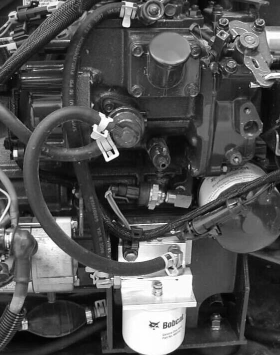
Open the vent (Item 1) [Figure 10-100-4] on the fuel filter housing.
Squeeze the hand pump (priming bulb) (Item 2) [Figure 10-100-4] until fuel flows from the vent with no air bubbles.
Close the vent (Item 1) [Figure 10-100-4] on the fuel filter housing.
It may be necessary to open the vent (Item 3) [Figure 10100-4] briefly while engine is running. Close the vent when the engine runs smoothly.
Figure
P-48388
P-48389
ENGINE LUBRICATION SYSTEM
Checking And Adding Engine Oil
Check the engine oil level every day before starting the engine for the work shift.
Figure 10-110-1
Park the machine on level ground. Open the rear door and remove the dipstick (Item 1) [Figure 10-110-1].
Keep the oil level between the marks on the dipstick.
Engine Oil Chart
Figure 10-110-2
Use a good quality motor oil that meets API Service Classification of CD or better See Oil Chart [Figure 10110-2]
Install the dipstick and close the rear door.
P-48392
P-48390
ENGINE LUBRICATION SYSTEM (CONT’D)
Removing And Replacing Oil And Filter
For the service interval for replacing the engine oil and filter.(See SERVICE SCHEDULE on Page 10-70-1.)
Run the engine until it is at operating temperature. Stop the engine.
Figure PM-3
WARNING
AVOID INJURY OR DEATH
Always clean up spilled fuel or oil. Keep heat, flames, sparks or lighted tobacco away from fuel and oil. Failure to use care around combustibles can cause explosion or fire which can result in injury or death.
Open the rear door and remove the drain hose from its storage position (Item 1) [Figure PM-3]
Remove the drain plug (Item 2) [Figure PM-3] and drain the oil into a container and recycle or dispose of used oil in an environmentally safe manner.
Reinstall the drain plug.
Remove the oil filter (Item 3) [Figure PM-3] and clean the filter housing surface.
Use genuine Bobcat filter only.
Put oil on the new filter gasket, install the filter and hand tighten.
Remove the fill cap (Item 3) [Figure 10-110-1].
Put oil in the engine. For the correct quantity (See Capacities on Page SPEC-10-4) and (See Capacities on Page SPEC-11-4). Install the fill cap. Do not overfill.
Start the engine and let it run for several minutes. Stop the engine and check for leaks at the filter.
Remove the dipstick (Item 1) [Figure 10-110-1] and check the oil level.
Add oil as needed if it is not at the top mark on the dipstick.
Install the dipstick and close the rear door.
W-2103-0807
HYDRAULIC / HYDROSTATIC SYSTEM
Checking And Adding Fluid
Use only recommended fluid in the hydraulic system. (See HYDRAULIC/HYDROSTATIC FLUID SPECIFICATIONS on Page SPEC-40-1.)
Put the loader on a level surface.
Lower the lift arms and tilt the Bob-Tach fully back.
Stop the engine.
Figure 10-120-1

Check the fluid level in the sight gauge (Item 1) [Figure 10120-1]
Open the rear door and raise the rear grill. Remove the fill cap (Item 2) [Figure 10-120-1]
Add fluid as needed to bring the level to the center of the sight gauge (Item 1) [Figure 10-120-1].
Install the fill cap (Item 2) [Figure 10-120-1].
Lower the rear grill and close the rear door.
Hydraulic / Hydrostatic Fluid Chart
Figure 10-120-2
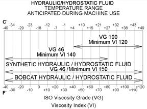
Use the correct hydraulic / hydrostatic fluid shown in hydraulic / hydrostatic fluid chart [Figure 10-120-2]
P-64023A
HYDRAULIC / HYDROSTATIC SYSTEM (CONT’D)
Removing And Replacing Hydraulic Fluid
See the SERVICE SCHEDULE for the service interval. (See SERVICE SCHEDULE on Page 10-70-1.)
Replace the fluid if it becomes contaminated or after major repair.
Always replace the hydraulic / hydrostatic filter, the hydraulic case drain filters and the hydraulic charge filter whenever the hydraulic fluid is replaced. (See Removing And Replacing Hydraulic / Hydrostatic Filter on Page 10120-2.)
Open the rear door and remove the fill cap.
Figure 10-120-3
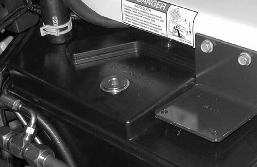
Raise the cab. (See Raising on Page 10-30-2.)
Remove the plug from the top of the reservoir (Item 1) [Figure 10-120-3]. Pump the fluid out of the reservoir and into a container.
Recycle or dispose of the used fluid in an environmentally safe manner.
WARNING
AVOID INJURY OR DEATH
Always clean up spilled fuel or oil. Keep heat, flames, sparks or lighted tobacco away from fuel and oil. Failure to use care around combustibles can cause explosion or fire which can result in injury or death.
W-2103-0807
Lower the cab. (See Lowering on Page 10-30-3.)
Add the correct fluid to the reservoir until the fluid level is at the center of the sight gauge. (See Checking And Adding Fluid on Page 10-30-1.)
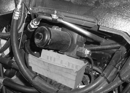
Removing And Replacing Hydraulic / Hydrostatic Filter
For the correct service interval (See SERVICE SCHEDULE on Page 10-70-1.)
Open the rear door.
Figure 10-120-4
Remove the filter element (Item 1) [Figure 10-120-4].
Clean the surface of the filter housing where the filter seal contacts the housing.
Put clean oil on the seal of the new filter element.
Install and hand tighten the filter element.
WARNING
AVOID INJURY OR DEATH
Always clean up spilled fuel or oil. Keep heat, flames, sparks or lighted tobacco away from fuel and oil. Failure to use care around combustibles can cause explosion or fire which can result in injury or death.
W-2103-0807
Close the rear door before operating the loader.
Start the engine and operate the loader hydraulic controls.
Stop the engine and check for leaks at the filter.
Check the fluid level in the reservoir and add as needed. (See Checking And Adding Fluid on Page 10-30-1.)
HYDRAULIC / HYDROSTATIC SYSTEM (CONT’D)
Removing And Replacing Hydraulic Case Drain Filters (Single Speed Loaders)
See the SERVICE SCHEDULE for the service interval. (See SERVICE SCHEDULE on Page 10-70-1.)
Figure 10-120-5
Remove both hydrostatic motor covers (Item 1) [Figure 10-120-5].
Figure 10-120-6
Remove the case drain filter assemblies (Item 1) [Figure 10-120-6] near the hydrostatic motors. Install the fittings from the old filter assembly onto the new filter assembly. Install motor covers.
Recycle or dispose of used fluid in an environmentally safe manner.
Start the engine and operate the loader hydraulic controls.
Stop the engine and check for leaks at the filter assemblies.
Check the fluid level in the reservoir and add as needed. (See Checking And Adding Fluid on Page 10-30-1.)
P-45492
P-45493
HYDRAULIC / HYDROSTATIC SYSTEM (CONT’D)
Removing And Replacing Hydraulic Case Drain Filters (Two-Speed Loaders)
Raise the lift arms. (See LIFT ARM SUPPORT DEVICE on Page 10-20-1.)
Raise the cab. (See Raising on Page 10-30-2.)
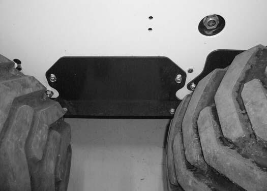
10-120-7
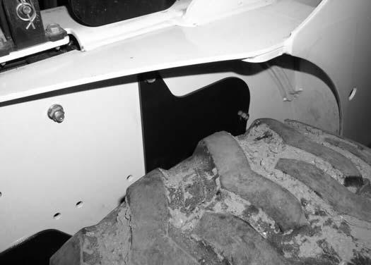
Remove the left side access cover (Item 1) [Figure 10120-7] near the rear tire.
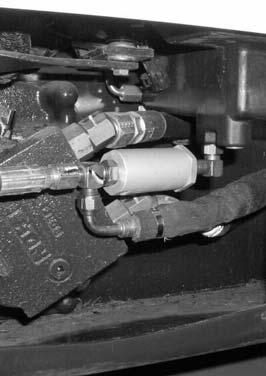
Figure 10-120-8
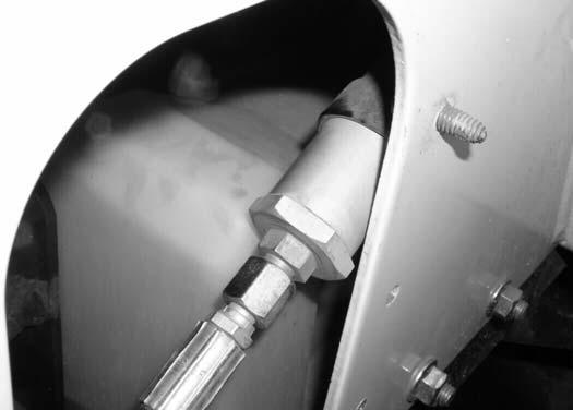
Remove the case drain filter assembly (Item 1) [Figure 10-120-8]. Install the fittings from the old filter assembly onto the new filter assembly.
Install new case drain filter assembly and replace the side access cover.
Recycle or dispose of used fluid in an environmentally safe manner.
SJC equipped machines skip ahead to [Figure 10-12010]
Figure 10-120-9
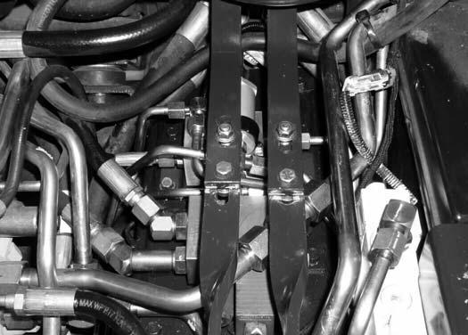
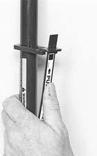
Scribe a mark across the top of the steering linkage bars (Item 1) [Figure 10-120-9] which are connected to the steering shaft on the control panel.
Remove the four steering linkage mounting bolts (Item 2) [Figure 10-120-9]
Figure
HYDRAULIC / HYDROSTATIC SYSTEM (CONT’D)
Removing And Replacing Hydraulic Case Drain Filters (Two-Speed Loaders) (Cont’d)
Figure 10-120-10
Remove the case drain filter assembly (Item 1) [Figure 10-120-10]. Install the fittings from the old filter assembly onto the new filter assembly.
Install new case drain filter assembly.
WARNING
AVOID INJURY OR DEATH
Always clean up spilled fuel or oil. Keep heat, flames, sparks or lighted tobacco away from fuel and oil. Failure to use care around combustibles can cause explosion or fire which can result in injury or death.
W-2103-0807
Standard Controls and ACS only: Align the marks on the steering linkage bars. Install the steering linkage mounting bolts (Item 2) in the proper orientation (two bolts facing up and two bolts facing down). Tighten the steering linkage mounting bolts to 35-40 ft.-lb. (47,5-54,2 N•m).
Recycle or dispose of the used fluid in an environmentally safe manner.
Lower the cab. (See Lowering on Page 10-30-3.)
Remove the lift arm support device and lower the lift arms (See LIFT ARM SUPPORT DEVICE on Page 10-20-1.)
Start the engine and operate the loader hydraulic controls.
WARNING
AVOID INJURY OR DEATH
Diesel fuel or hydraulic fluid under pressure can penetrate skin or eyes, causing serious injury or death. Fluid leaks under pressure may not be visible. Use a piece of cardboard or wood to find leaks. Do not use your bare hand. Wear safety goggles. If fluid enters skin or eyes, get immediate medical attention from a physician familiar with this injury.
W-2072-0807
Stop the engine and check for leaks at the filter assemblies.
Check the fluid level in the reservoir and add as needed. (See Checking And Adding Fluid on Page 10-120-1.)
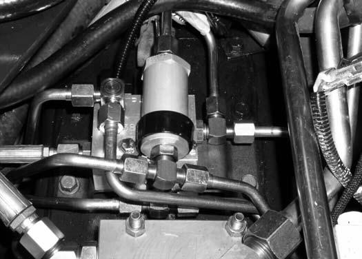
HYDRAULIC / HYDROSTATIC SYSTEM (CONT’D)
Removing And Replacing Hydraulic Charge Filter
See the SERVICE SCHEDULE for the service interval. (See SERVICE SCHEDULE on Page 10-70-1.)
Raise the cab. (See Raising on Page 10-30-2.)
Earlier Models
Figure 10-120-11
Remove the filter (Item 1) [Figure 10-120-11]
Clean the surface of the filter housing where the filter seal contacts the housing.
Put clean oil on the seal of the new filter. Install and hand tighten the new filter.
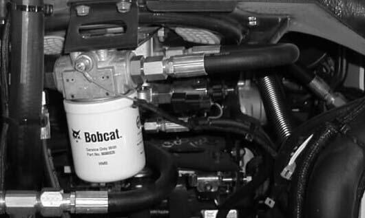
Later Models
Figure 10-120-12
Place a suitable container below the filter housing and remove the filter housing (Item 1) [Figure 10-120-12]
Recycle or dispose of used fluid in an environmentally safe manner.
Figure 10-120-13
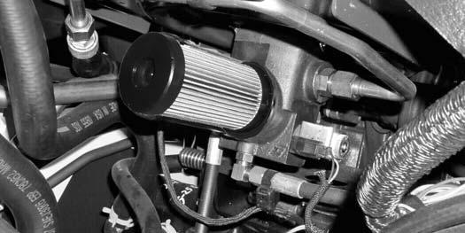
Remove and discard the filter element (Item 1) [Figure 10-120-13]
Clean the surface of the filter housing and the filter base where they contact the filter element seal.
Put clean oil on the seal of the new filter element. Install the element on the filter base. Install and tighten the filter housing to 35-40 ft.-lb. (47-54 N•m) torque.
All Models
AVOID INJURY OR DEATH
Always clean up spilled fuel or oil. Keep heat, flames, sparks or lighted tobacco away from fuel and oil. Failure to use care around combustibles can cause explosion or fire which can result in injury or death.
AVOID INJURY OR DEATH
Diesel fuel or hydraulic fluid under pressure can penetrate skin or eyes, causing serious injury or death. Fluid leaks under pressure may not be visible. Use a piece of cardboard or wood to find leaks. Do not use your bare hand. Wear safety goggles. If fluid enters skin or eyes, get immediate medical attention from a physician familiar with this injury.
W-2072-0807
Lower the operator cab. (See Lowering on Page 10-303.)
Start the engine and operate the loader. Stop the engine and check for leaks at the filter.
Check the fluid level in the reservoir and add as needed. (See Checking And Adding Fluid on Page 10-120-1.)
HYDRAULIC / HYDROSTATIC SYSTEM (CONT’D)
Breather Cap
See the SERVICE SCHEDULE for the correct replacement interval. (See SERVICE SCHEDULE on Page 10-70-1.)
Raise the cab. (See Raising on Page 10-30-2.)
Figure 10-120-14
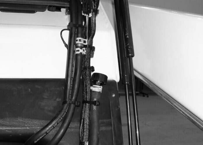
Remove and discard the hydraulic breather cap (Item 1) [Figure 10-120-14].
Install new breather.
Lower the cab. (See Lowering on Page 10-30-3.)
P-48091
FINAL DRIVE TRANSMISSION (CHAINCASE)
Checking And Adding Oil
The chaincase contains the final drive sprockets and chains and uses the same type of oil as the hydraulic / hydrostatic system (See Hydraulic System on Page SPEC-10-3.) and (See Hydraulic System on Page SPEC11-3.)
Stop the loader on a level surface.
Stop the engine.
Figure 10-130-1
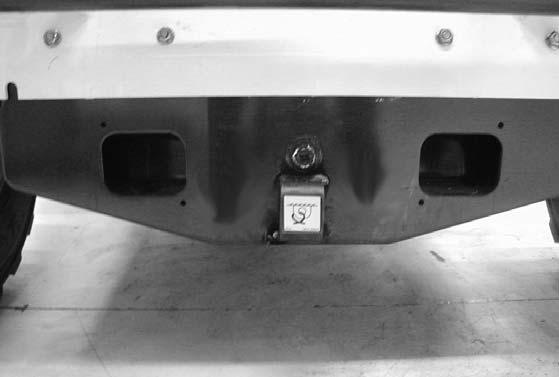
Remove the drain plug (Item 1) [Figure 10-130-1] from the front of the chaincase housing.
If oil can be reached with the tip of the your finger through the hole, the oil level is correct.
If the level is low, add oil through the check plug hole until the oil flows from the hole.
Install and tighten the plug.
Removing And Replacing Oil
Remove the check plug (Item 1) [Figure 10-130-1] from the front of the chaincase housing.
Figure 10-130-2
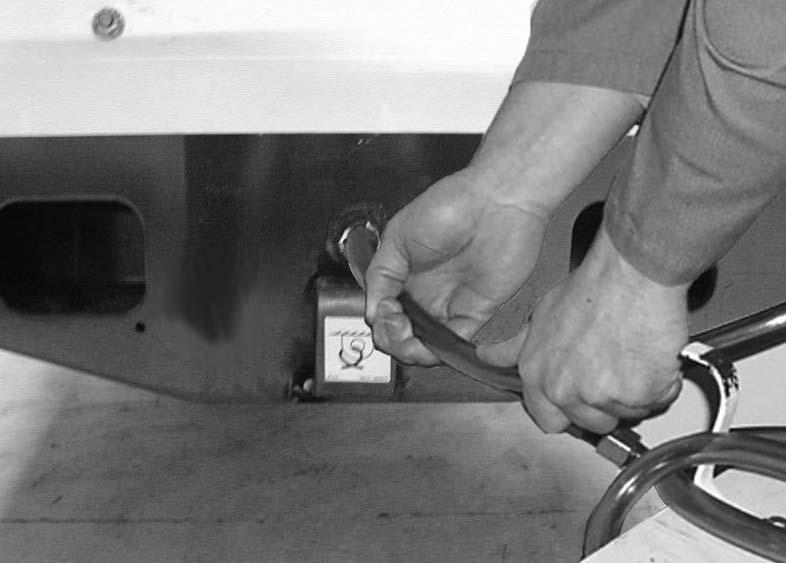
Use a pump to remove the oil from the chaincase [Figure 10-130-2]
Recycle or dispose of the used oil in an environmentally safe manner.
P-31287A
BOB-TACH (HAND LEVER)
Inspection And Maintenance
Figure 10-140-1
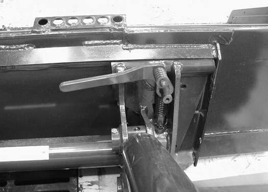
Move the Bob-Tach levers to engage the wedges [Figure 10-140-1]
The levers and wedges must move freely.
WARNING
Bob-Tach wedges must extend through the holes in attachment. Lever(s) must be fully down and locked. Failure to secure wedges can allow attachment to come off and cause injury or death.
W-2102-0497
Figure 10-140-2
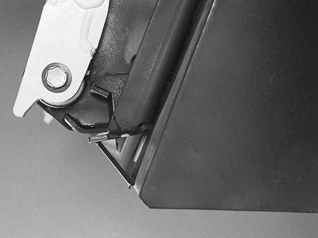
2 1
Wedge must contact lower edge of hole in the attachment.
The wedges (Item 1) [Figure 10-140-2] must extend through the holes in the attachment mounting frame.
The spring loaded wedge (Item 1) [Figure 10-140-2] must contact the lower edge of the hole in the attachment (Item 2) [Figure 10-140-2]
If the wedge does not contact the lower edge of the hole [Figure 10-140-2], the attachment will be loose and can come off the Bob-Tach.
Figure 10-140-3
Inspect the mounting frame on the attachment and BobTach, linkages and wedges for excessive wear or damage [Figure 10-140-3]. Replace any parts that are damaged, bent or missing. Keep all fasteners tight.
Look for cracked welds. Contact your Bobcat dealer for repair or replacement parts.
Lubricate the wedges. (See SERVICE SCHEDULE on Page 10-70-1) and (See LUBRICATING THE LOADER on Page 10-150-1).
P-31693
N-17022
B-15177
B-17460
BOB-TACH (POWER)
This machine may be equipped with a Power Bob-Tach.
Inspection And Maintenance
Figure 10-141-1
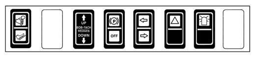
Figure 10-141-2
Wedge must contact lower edge of hole in the attachment.
Push and hold the BOB-TACH "WEDGES UP" switch until wedges are fully raised. Push and hold the BOBTACH "WEDGES DOWN" switch [Figure 10-141-1] until the wedges are fully down.
The levers and wedges must move freely.
WARNING
Bob-Tach wedges must extend through the holes in attachment. Lever(s) must be fully down and locked. Failure to secure wedges can allow attachment to come off and cause injury or death.
W-2102-0497
The wedges must extend through the holes in the attachment mounting frame (Item 1) [Figure 10-141-2]
The spring loaded wedge (Item 1) must contact the lower edge of the hole in the attachment (Item 2) [Figure 10141-2]
If the wedge does not contact the lower edge of the hole [Figure 10-141-2], the attachment will be loose and can come off the Bob-Tach.
B-15993N
N-17022
B-15177
BOB-TACH (POWER)
Inspection And Maintenance (Cont’d)
Figure 10-141-3
Inspect the mounting frame on the attachment and the Bob-Tach, linkages and wedges for excessive wear or damage [Figure 10-141-3]. Replace any parts that are damaged, bent, or missing. Keep all fasteners tight.
Look for cracked welds. Contact your Bobcat dealer for repair or replacement parts.
Lubricate the wedges. (See SERVICE SCHEDULE on Page 10-70-1) and (See LUBRICATING THE LOADER on Page 10-150-1).
B-17460
LUBRICATING THE LOADER
Lubrication Locations
Lubricate the loader as specified for the best performance of the loader. (See SERVICE SCHEDULE on Page 10-70-1.)
Record the operating hours each time you lubricate the Bobcat Loader.
Always use a good quality lithium based multi-purpose grease when you lubricate the loader. Apply the lubricant until extra grease shows.
Lubricate the following locations on the loader:
10-150-4
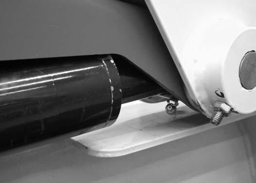
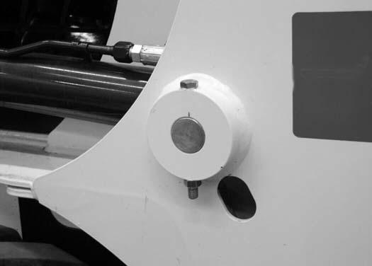
10-150-6
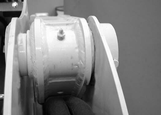
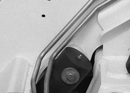
Figure
1.Rod End Lift Cylinder (Both Sides) [Figure 10-150-4]
Figure 10-150-5
2.Base End Lift Cylinder (Both Sides) [Figure 10-1505]
Figure
3.Lift Arm Pivot Pin (Both Sides) [Figure 10-150-6]
Figure 10-150-7
4.Base End Tilt Cylinder (Both Sides) [Figure 10-1507] P-43782
LUBRICATING THE LOADER (CONT’D)
Lubrication Locations (Cont’d)
Figure 10-150-8
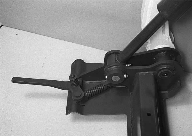
5.Rod End Tilt Cylinder (Both Sides) [Figure 10-150-8]
6.Bob-Tach Pivot Pin (Both Sides) [Figure 10-150-8]
Figure 10-150-9
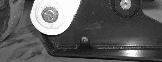
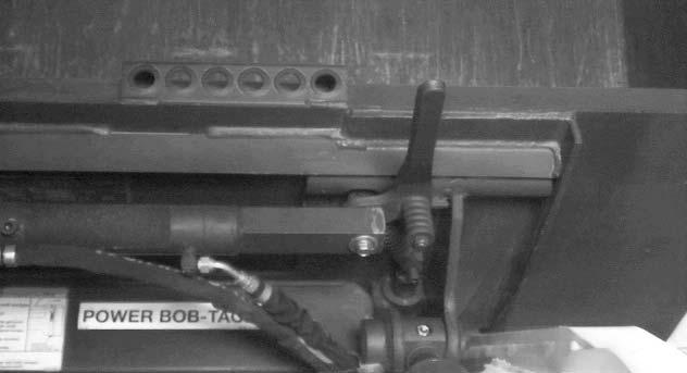
7.Bob-Tach Wedge (Both Sides) [Figure 10-150-9]
8.Power Bob-Tach linkage (Both Sides) [Figure 10150-9].
Figure 10-150-10
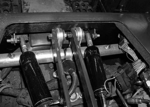
9.250 Hours: Steering Lever Shaft (2) [Figure 10-15010]
Wheel Nuts
Figure PM-11
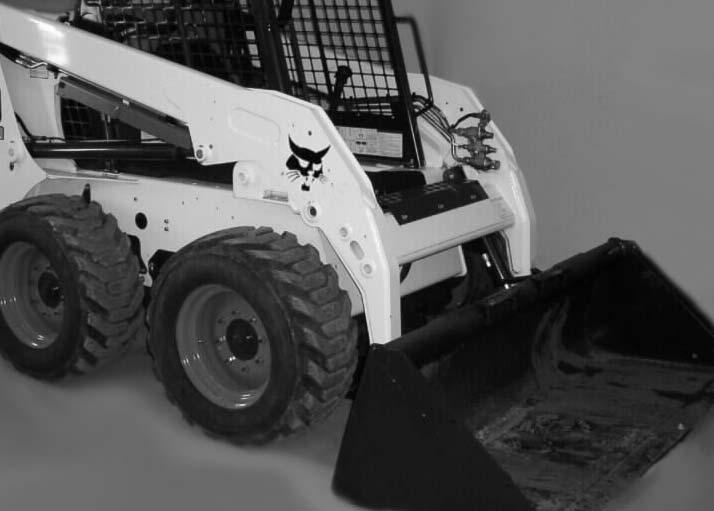
See the SERVICE SCHEDULE for the service interval to check the wheel nuts [Figure PM-11]. (See SERVICE SCHEDULE on Page 10-70-1.)
When installing wheel nuts, tighten to 160 ft.-lb. (217 N•m) torque.
When checking wheel nut torque, set the torque wrench to 140 ft.-lb. (190 N•m) to prevent over-tightening.
Rotating
Check the tires regularly for wear, damage and pressure. Inflate tires to the maximum pressure shown on the sidewall of the tire.
Figure 10-160-12
Rear tires usually wear faster than front tires. To keep tire wear even, move the front tires to the rear and rear tires to the front [Figure 10-160-12]
It is important to keep the same size tires on each side of the loader. If different sizes are used, each tire will be turning at a different rate and cause excessive wear. The tread bars of all the tires must face the same direction.
Recommended tire pressure must be maintained to avoid excessive tire wear and loss of stability and handling capability. Check for correct pressure before operating the loader.
Mounting
Tires are to be repaired only by an authorized person using the proper procedures and safe equipment.
Tires and rims must always be checked for correct size before mounting. Check rim and tire bead for damage.
The rim flange must be cleaned and free of rust.
The tire bead and rim flange must be lubricated with a rubber lubricant before mounting the tire.
Avoid excessive pressure which can rupture the tire and cause serious injury or death.
During inflation of the tire, check the tire pressure frequently to avoid over inflation.
WARNING
AVOID INJURY OR DEATH
Do not inflate tires above specified pressure. Failure to use correct tire mounting procedure can cause an explosion which can result in injury or death.
W-2078-1007
Inflate tires to the MAXIMUM pressure shown on the sidewall of the tire. DO NOT mix brands of tires used on the same loader.
I-2057-0794
Cleaning Procedure
Use the correct service interval for cleaning the spark arrestor muffler. (See SERVICE SCHEDULE on Page 10-70-1.)
Do not operate the loader with a defective exhaust system.
IMPORTANT
This loader is factory equipped with a U.S.D.A. Forestry Service approved spark arrestor muffler. It is necessary to do maintenance on this spark arrestor muffler to keep it in working condition. The spark arrestor muffler must be serviced by dumping the spark chamber every 100 hours of operation.
If this machine is operated on flammable forest, brush or grass covered land, it must be equipped with a spark arrestor attached to the exhaust system and maintained in working order. Failure to do so will be in violation of California State Law, Section 4442 PRC.
Consult local laws and regulations for spark arrestor requirements I-2022-0807
Stop the engine and open the rear door.
Figure 10-170-1
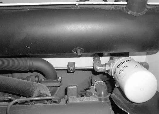
Remove the plug (Item 1) [Figure 10-170-1] from the bottom of the muffler.
WARNING
When the engine is running during service, the steering levers must be in neutral and the parking brake engaged. Failure to do so can cause injury or death.
W-2006-0284
Start the engine and run for about 10 seconds while a second person, wearing safety goggles, holds a piece of wood over the outlet of the muffler.
This will force contaminants out through the cleanout hole.
Stop the engine.
Install and tighten the plug.
Lower the rear grill and close the rear door.
WARNING
AVOID INJURY OR DEATH
When an engine is running in an enclosed area, fresh air must be added to avoid concentration of exhaust fumes. If the engine is stationary, vent the exhaust outside. Exhaust fumes contain odorless, invisible gases which can kill without warning.
W-2050-0807
WARNING
Stop engine and allow the muffler to cool before cleaning the spark chamber. Wear safety goggles. Failure to obey can cause serious injury.
W-2011-1285
WARNING
Never use machine in atmosphere with explosive dust or gases or where exhaust can contact flammable material. Failure to obey warnings can cause injury or death.
W-2068-1285