

Document Title: Function Group: Information Type: Date:
Description 400
Profile:
Description
Information 2014/6/9 0
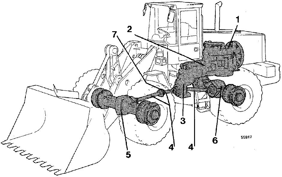
The engine output torque is transferred to the transmission via the torque converter. The converter has a fixed stator. The stator multiplies the torque. The multiplication is at its greatest when the engine is running at high speed and the turbine rotor is stationary, e.g. when starting the machine. The torque from the torque converter passes through the transmission and dropbox to the drive axles. In the differential gear the torque is divided out to the planetary hub gears and the wheels. The transmission has four speed gears and two directional gears.
Document Title: Function Group: Information Type: Date: APS (Automatic Power Shift) 420 Service Information 2014/6/9 0
Profile:
APS (Automatic Power Shift)
Description
L150 and L180 are as standard provided with APS (Automatic Power Shift), which is included in the control unit of the Contronic system.
2nd gear is the basic gear and the gear in which the machine normally starts when operating with the selector in the "A" (Automatic) position. During engine braking the accelerator control is fully released and the downshifting / engine braking button, SW105, is pressed in. Downshifting takes place at the correct moment for the greatest possible engine braking from 4th via 3rd to 2nd. If 1st gear is required, press in the kick-down button and 1st gear will be engaged, if the travelling speed is below 10 km/h (6 mph). This takes place regardless of which gear was engaged initially.
Upshifting from 2nd to 3rd reverse takes place at a comparatively high speed. In that way the operator can decide when upshifting should occur with the aid of the accelerator control.
If the downshifting / engine braking button, SW105, is kept pressed in while accelerating, upshifting is prevented, see also [Invalid linktarget] .
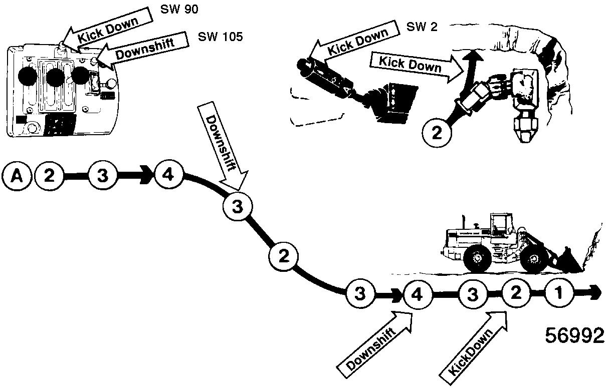
Figure 1
Gear shifting, general principle
Description of function of manual gear shifting
Gear shifting
Gear selector control positions 1, 2 and 3 are manual positions, i.e. the operator selects the gear he or she prefers.
Over-speeding protection
During downshifting the control programme always checks that the speed is not too high for the selected gea. In which case the engaged gear remains engaged until the speed has dropped to within the permissible range.
Kick-down function
Kick-down can only be activated in selector position 2.
1st gear is engaged if the speed is below 10 km/h (6 mph) within 5 seconds from when the kick-down switch is activated. 1st gear remains engaged for at least 5 seconds, then upshifting to 2nd gear takes place when the gear-shifting point has been reached. When changing travelling direction, the kick-down function ceases immediately and upshifting to 2nd gear takes place.
Changing travelling direction
The machine starts off in the new direction in the same gear as before the new direction was selected.
Description of function during automatic gear shifting
Start (selector position A)
When starting from stationary, the machine moves off in 2nd gear. If the machine is already moving, 3rd gear will be engaged.
Gear shifting
Gear shifting is automatic. Conditions for gear shifting are a combination of travelling speed and engine speed. Gear shifting takes place between gears:
Forward: 2nd-3rd-4th
Reverse: 2nd-3rd
Gear shifting down to 1st takes place only after the kick-down switch has been activated. Upshifting to 2nd then takes place automatically or when changing travelling direction. The gear-shifting points vary depending on whether the engine is pulling or braking, according to the table shown below.
Kick-down function
Kick-down means that the operator requests gear shifting to 1st gear by activating the kick-down switch. 1st gear will be engaged, if the speed is below 10 km/h (6 mph) within 5 seconds from when the kick-down switch is activated.
1st gear remains engaged for at least 5 seconds, then upshifting takes place according to the gear-shifting programme. When changing travelling direction the kick-down function ceases immediately and upshifting to 2nd takes place.
Changing travelling direction
At low speed a change of direction takes place in 2nd gear and at higher speed in 3rd gear and downshifting to 2nd only takes place when the machine has stopped and before it begins to move off in the opposite direction.
Speeds below approx. 18 km/h (11.2 mph):
2nd forward to 2nd reverse
3rd forward to 2nd reverse
4th forward to 2nd reverse
Speeds above approx. 18 km/h (11.2 mph):
3rd forward to 3rd reverse to 2nd reverse
4th forward to 3rd reverse to 2nd reverse
NOTE!
4th gear is blocked in connection with reverse gear, otherwise downshifting from reverse to forward takes place according to the description above.
Document Title: Function Group: Information Type: Date: Downshifting switch, engine braking 420 Service Information 2014/6/9 0
Profile:
Downshifting switch, engine braking
With the aid of switch SW105 the operator can achieve immediate downshifting in order to retard (brake) the machine. When SW105 is activated, current is supplied to ECU connection EB14 and downshifting takes place as shown below. At speeds above approx. 22 km/h (13.7 mph):
downshifting 4th to 3rd 3rd gear – no downshifting
At speeds below approx. 22 km/h (13.7 mph):
downshifting 4th to 2nd downshifting 3rd to 2nd
If the switch remains activated, upshifting is prevented as long as the engine and/or transmission overspeeding protection do not force upshifting to take place.
Document Title: Function Group: Information Type: Date: Dual control, gear shifting forward – reverse 420
Service Information 2014/6/9 0
Profile:
Dual control, gear shifting forward – reverse
General description
When the equipment dual control is fitted, the operator can shift between forward – neutral and reverse with toggle switch SW108 on the control lever carrie.
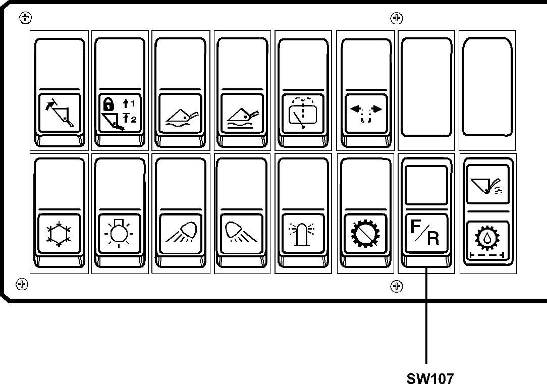
The system is activated with switch SW107 on the right instrument panel.
The ordinary selector control has priority over the switch on the control lever carrie. This means that the dual control becomes disengaged if the gear selector control is moved to position forward or reverse and dual control must be activated again with switch SW107.
Description of function
With the ignition key in position 1, current is supplied to switch SW107 via fuse FU29 and relay RE20 (30 – 87A). When switch SW107 is activated, the coil in relay RE21 is supplied with current. Relay RE21 is activated and then receives holding current via terminals 30 – 87 (RE21).
Switch SW108 now receives current via relay RE20 (30 – 87A), relay RE21 (30 – 87) and diode Di 2.21
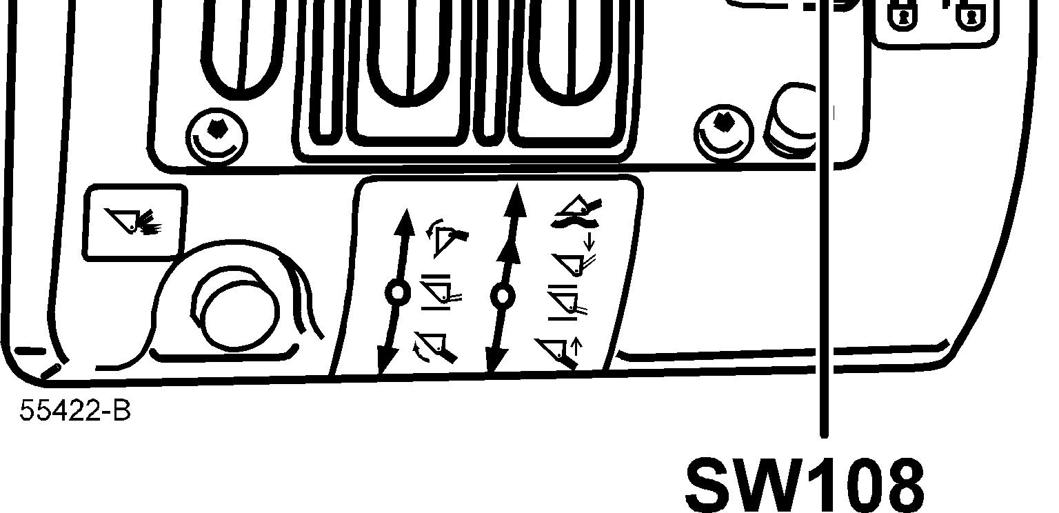
Figure 1
Control lever carrier, working hydraulics
Gear shifting
When switch SW108 is moved to position forward (F) current is supplied to the ECU connection EA17 and to the coil in relay RE11 which is activated, see also description [Invalid linktarget]. When switch SW108 is moved to position reverse (R) current is supplied to the ECU connection EA18 and to the coil in relay RE11 which is activated.
The function of relay RE11 and condenser C2.1 is shown in description [Invalid linktarget]
If the ordinary selector control SW2A is moved for example to position forward (F) the coil in relay RE20 receives current via fuse FU29, SW2A (GA1 – F) and diode Di 2.13.
Relay RE20 is activated and then receives holding current via terminals 30 – 87 (RE20) and switch SW107 (6 – 8).
When relay RE20 is activated, the current supply to the dual control switch SW108 is interrupted, and the dual control is disconnected.
The dual control must be re-activated with switch SW107, and the selector control SW2A must be in neutral position.


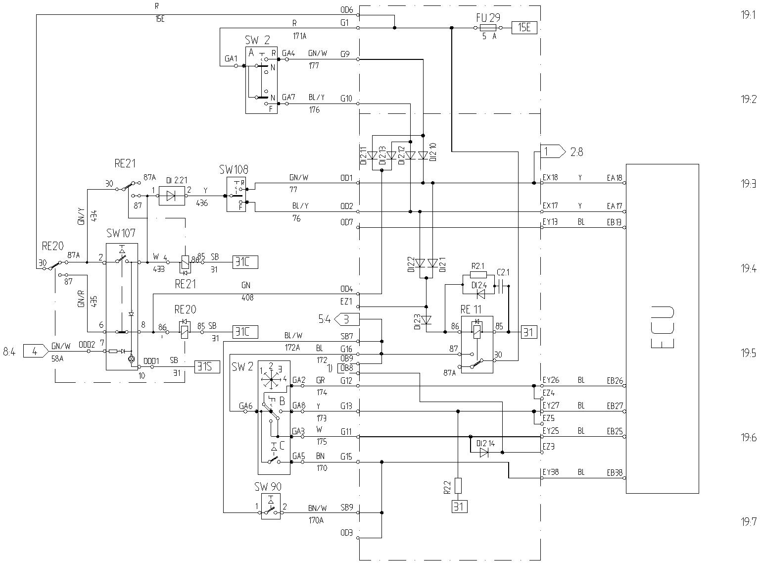
Wiring diagram, Dual control, forward
Document Title: Function Group: Information Type: Date: Engine power reduction when changing travelling direction 420 Service Information 2014/6/9 0
Profile:
Engine power reduction when changing travelling direction
Stop solenoid MA64 which is connected to the injection pump stop control is also used to limit the engine power when changing travelling direction at too high a speed.
Earlier type control unit
When operating in 3rd or 4th gea, engine power reduction takes place if the travelling speed exceeds approx. 18 km/h (11.2 mph) at the same time as the engine speed exceeds approx. 1900 rpm.
Later type control unit (w.e.fr. programme version 06)
When operating in 2nd, 3rd or 4th gea, engine power reduction takes place if the travelling speed exceeds approx. 14 km/h (8.7 mph) at the same time as the engine speed exceeds approx. 1800 rpm.
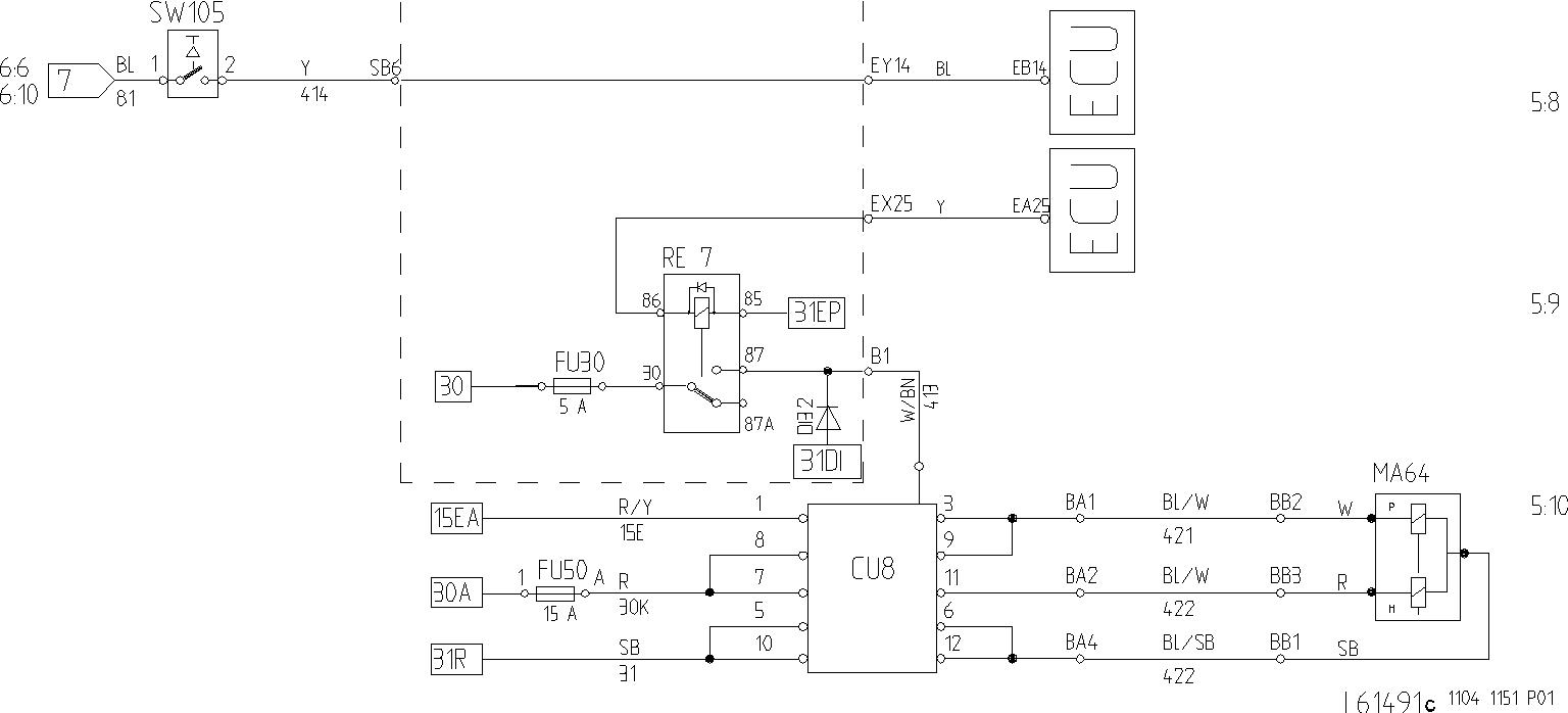
Description
See [Invalid linktarget]
Current is supplied via ECU connection EA25 to the coil in relay RE7 which is then activated.
The electronic control unit CU8 is now supplied with current via fuse FU30 and relay RE7 (30 – 87).
The electronic control unit CU8 now interrupts the earth connection to stop solenoid MA64 and engine power reduction takes place.
When the engine speed is below approx. 1400 rpm, the stop solenoid is again connected to earth and returns to normal operating position.
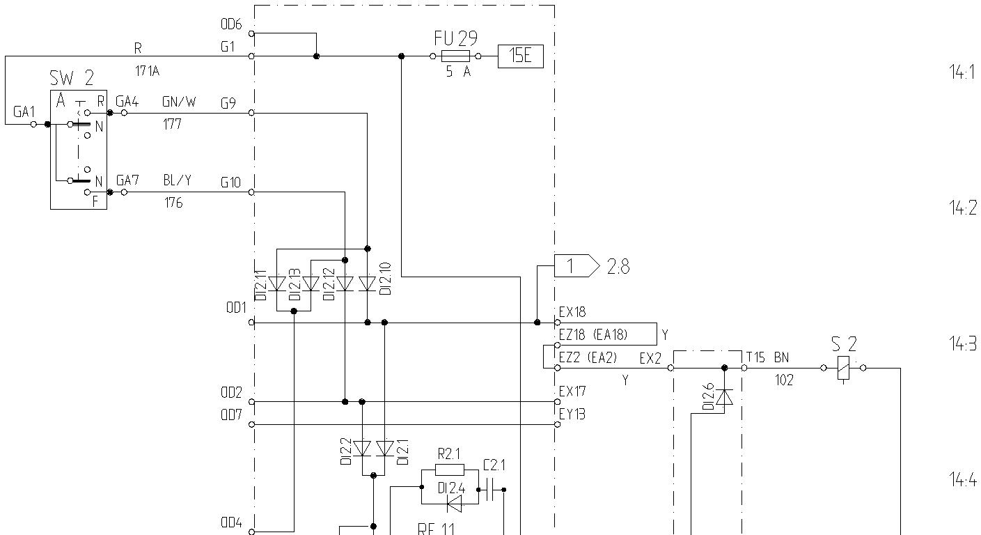
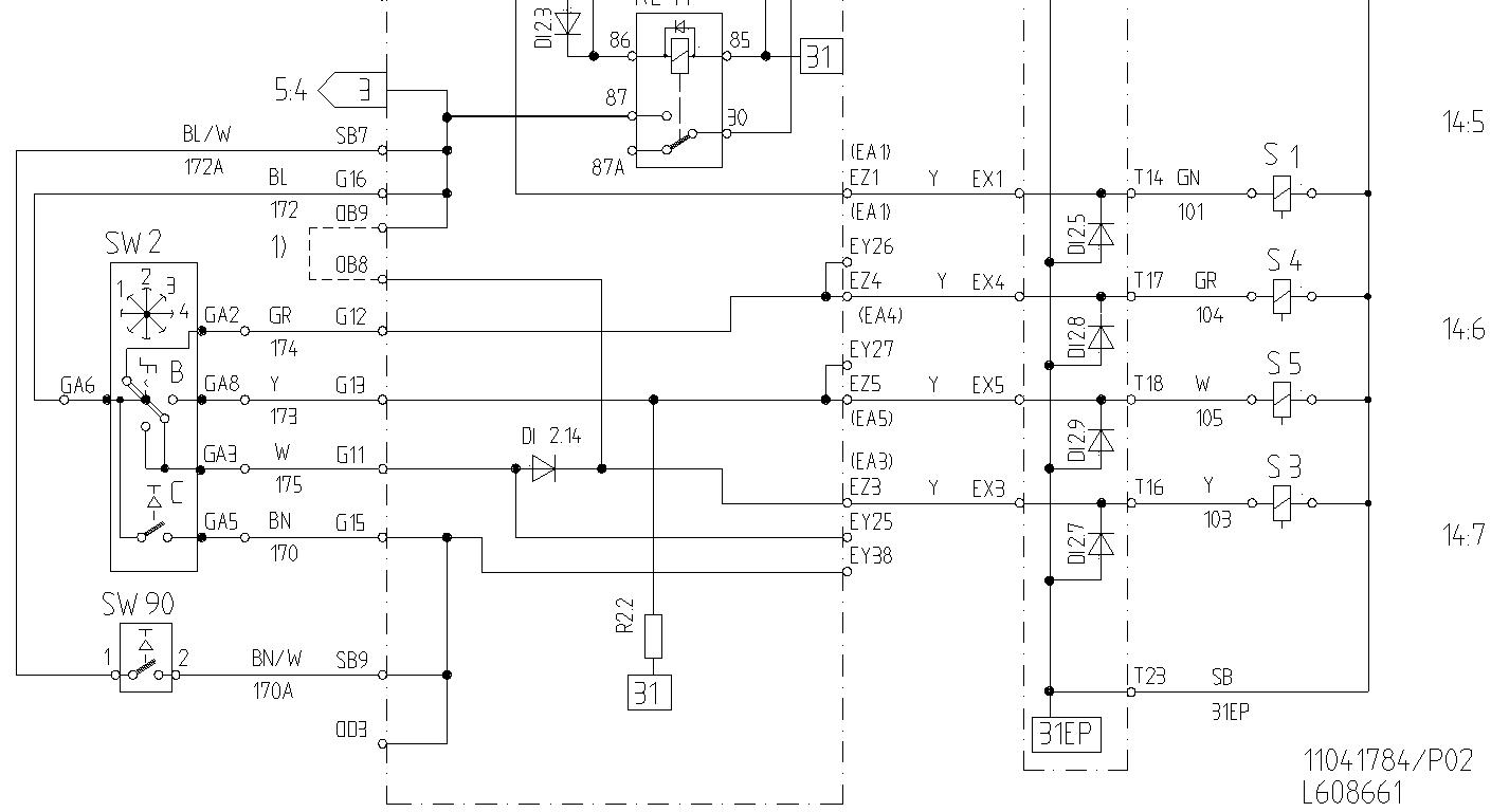
Figure 1
Wiring diagram, gear shifting
GEAR SHIFTING, signal to ECU from selector control, see
Gear
Forward 1
ECU
Signal,in
EA17
EB25
EB26
Feed, out
Current to solenoid
Forward 2 EA17 EA1 S1
EB25 EA3 S3
Forward 3 EA17
Forward 4 EA17 EA1 S1
Reverse 1
EB27 EA5 S5
EB25 EA3 S3
EB26 EA4 S4
Reverse 2
Reverse 3
EB25
EA18
Reverse 4 EA18
EB27
Kick-down
EA3
EA1
EA2
EA1
EA2
EA5
EB38
S3
S1
S2
S1
S2
S5
See Gear 1 forward and Gear 1 reverse
If an open circuit or a short circuit should occur in the circuit from the ECU out to solenoids S1 or S2 the ECU will block the feed to all solenoids (S1 – S5).
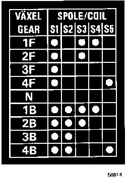
Figure 2
The gear shifting diagram shows the solenoid which are activated for the respective gear. For instance for 1F: S1,S3 nad S4 are activated

S1 =Neutral – Drive
S2 =Forward – Reverse
S3 =High – Low
(3rd-4th) – (1st-2nd)
S4 =2nd – 1st
S5 =3rd – 4th = Activated solenoid
Document Title: Function Group: Information Type: Date: Gear shifting, signal to the ECU from the selector control 420 Service Information 2014/6/9 0
Profile:
Gear shifting, signal to the ECU from the selector control
See Figure 1
For example 2nd gear forward
The selector control SW2A for forward/reverse is supplied with current via fuse FU29. When the selector control is moved to 2nd gear forward, the following happens:
The ECU connection EA17 is supplied with current via fuse FU29, gear selector control SW2A (GA1 – F), diode DI 2.12 and the circuit board connection EX17. Solenoid S1 is supplied with current from the ECU connection EA1.
The coil in relay RE11 and the condenser C2.1 also obtain current via gear selector control SW2A (GA1-F), diodes DI 2.12, Di 2.2 and Di 2.3. Relay RE11 is activated and current is now supplied via 30 – 87 to the selector control SW2B for the speed gears 1 – 4 and to switch SW2C (kick-down) and SW90 (separate kick-down).
The ECU connection EB25 obtains current via speed selector control SW2B (GA6 – GA3) and the circuit board connection EY25. Solenoid S3 receives current from the ECU connection EA3 and 2nd gear forward is engaged. Relay RE11 also supplies current to the coil in relay RE13 via terminals 30 – 87 and also to circuit 5:3. Relay RE13 works as a starter lock-out when the selector control for forward/reverse has been moved to either forward or reverse, see also Section 2.
The condenser C2.1 delays the engine power reduction for relay RE11 by approx. 0.8 seconds. The condenser C2.1 supplies the coil in relay RE11 with current when the selector control is moved from position forward to reverse or vice versa. This means that relay RE11 is maintained in activated position and the speed gears (1 – 4) are not disengaged when shifting from forward to reverse or vice versa.
1
Wiring diagram
S1 and S3, see circuit 4:1 – 4:2
Connections OB9 – OB8, see explanationin Section 6, secondary steering
Document Title: Function Group: Information Type: Date:
Operating with ECU disconnected<br />HT210 product no. 30882<br / >HT220 product no. 30883
Profile:
420
Service Information 2014/6/9 0
Operating with ECU disconnected
Tools:
Nipple, part no. 957030, 2 pcs forward drive, 4 pcs reverse drive
Hose, part no. 13932807, 1 pc forward drive, 2 pcs reverse drive
NOTE!
Always turn off the engine before connecting oil hoses. Otherwise the machine is set in motion with increased risk of accidents as a consequence.
Operating forward with ECU disconnected
Remove the pressure checking point for the main pressure on the pressure checking panel and the plug N/D on the gear selector valve and fit nipples according to . Figure 2
Connect an oil line between the nipples. Keep the selector control in the neutral position and start the engine. 3rd gear forward will now be engaged.
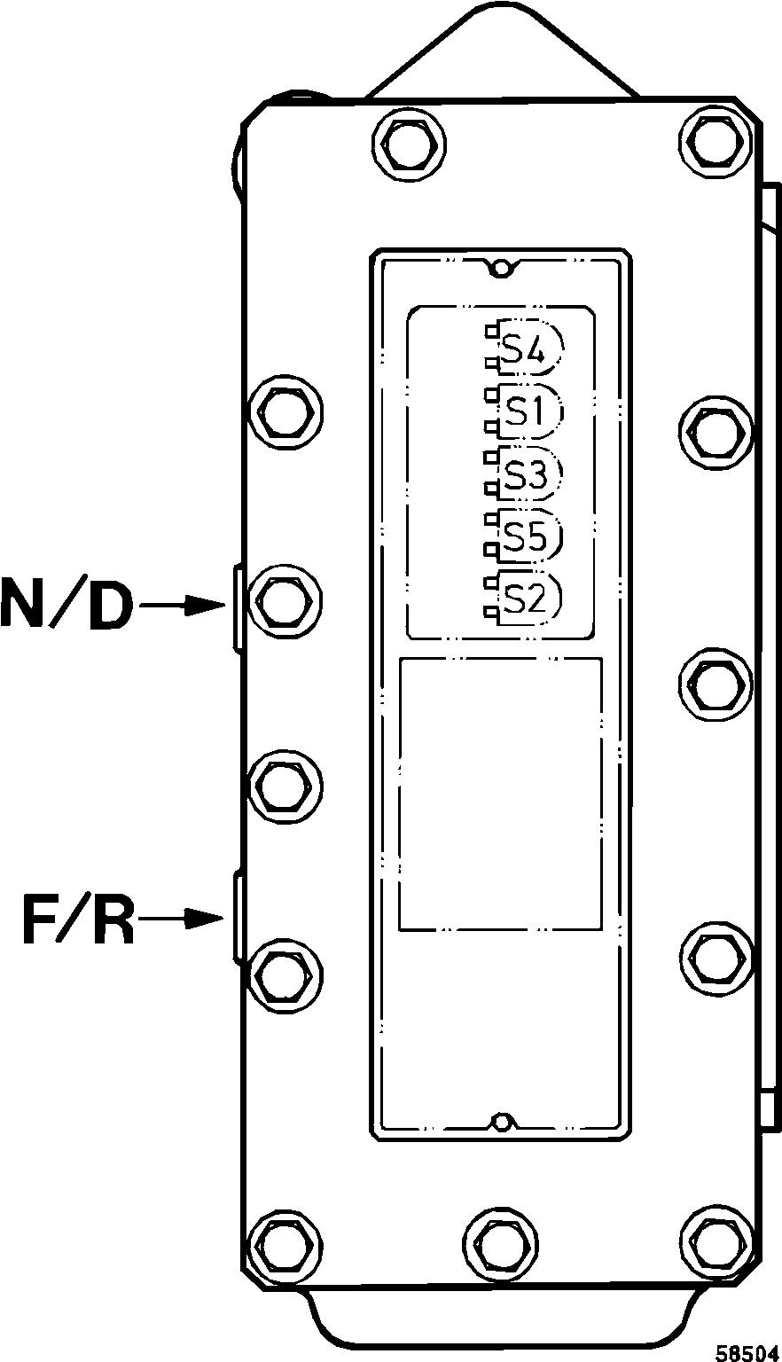
1
Gear selector valve
N/D
F/R
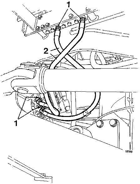
Operating rearward with ECU disconnected
Valve spool Neutral – Drive
Valve spool Forward – Reverse
Remove the measuring points for the main pressure and the 3rd clutch pressure on the pressure checking panel and plugs
N/D and F/R on the gear selector valve. Fit nipples according to Figure 3
Connect an oil line between the nipples. Keep the selector control in neutral position and start the engine.
3rd gear reverse will now be engaged.
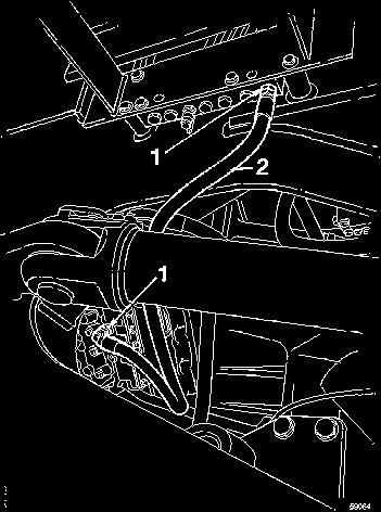
Connection for operating forward with ECU disconnected
1
2
3
Connection for operating rearward with ECU disconnected
1
Nipple, part no. 957030
Hose, part no. 13932807
Nipple, part no. 957030 2
Hose, part no. 13932807
4
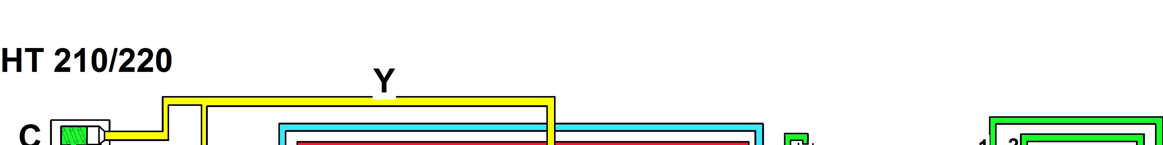
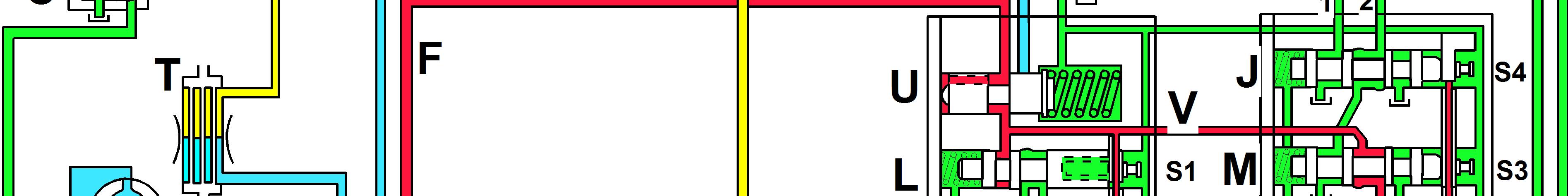
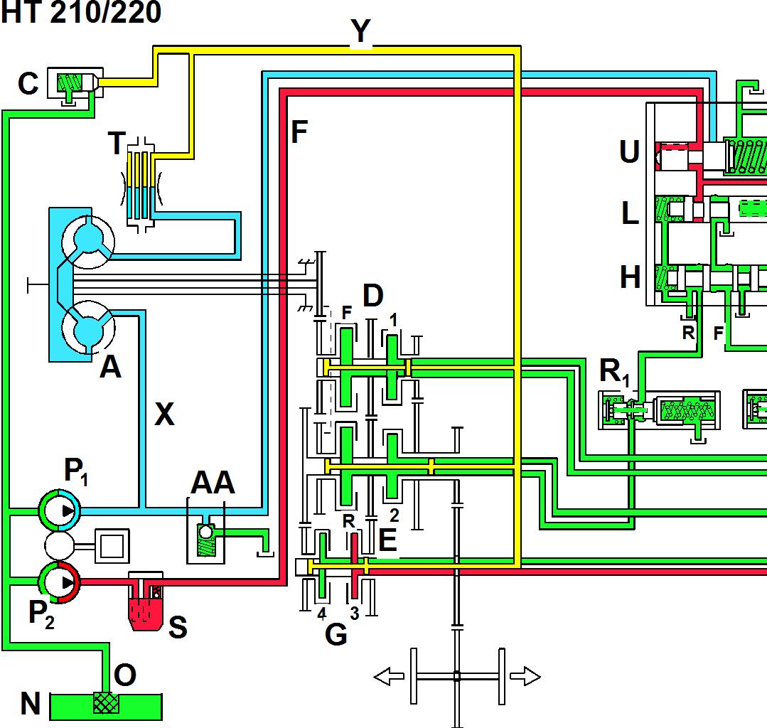
Diagram, neutral position
A e converter
C Lubricating oil valve
D Clutch, forward – 1st
E Clutch, reverse – 2nd
F Connecting line, filter – gear selector valve
G Clutch, 3rd – 4th
H Selector spool, forward and reverse
J Selector spool, 1st and 2nd
K Selector spool, 3rd and 4th
L Selector spool, neutral and drive
M Selector spool, high and low
N Oil tank
O Strainer

Suggest:
If the above button click is invalid.
Please download this document first, and then click the above link to download the complete manual.
Thank you so much for reading
P1
P2
R1
R2
Pump, torque converter / lubrication
Pump, gear selector valve
Reverse gear trimmer valve
Forward gear trimmer valve
S Filter
T
U
Oilcooler
Pressure-limiting valve
V Pressure line
X Line to torque converter
Y Lubricating oil line
AA
Colour designation
Torque converter safety valve
Red Clutch pressure
Blue Torque converter pressure
Yellow Lubricating oil pressure
Green Atmospheric pressure
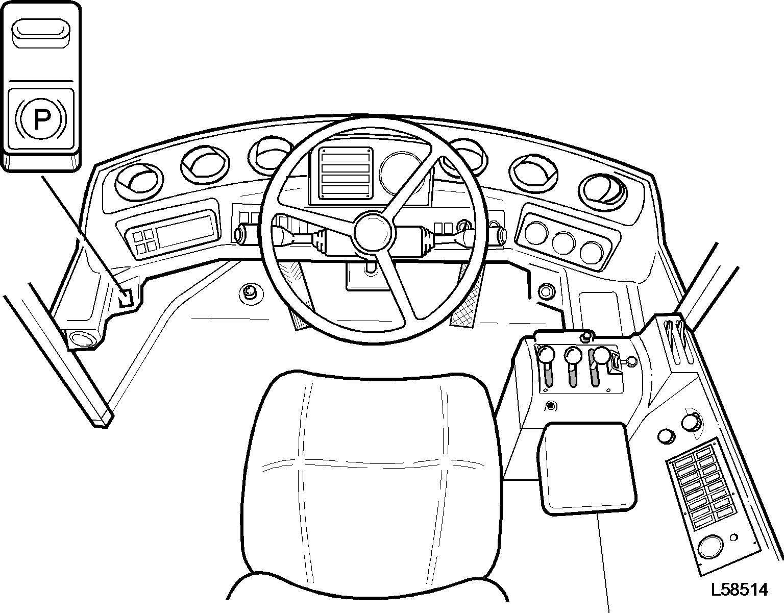
Figure 5
The gear-shifting diagram shows the solenoids which are activated for the respective gear. For instance for 1F: S1, S3 and S4 are