FOREWORD CONTENTS
SECTION 1
SECTION 2
WHEEL EXCAVATOR
Safety Hints Specifications
STRUCTURE AND FUNCTION
Group 1 Pump Device
Group 2 Main Control Valve
Group 3 Swing Device
Group 4 Travel Motor
Group 5 RCV Lever
Group 6 RCV Pedal
Group 7 Brake Pedal(Valve)
Group 8 Gear box
Group 9 Steering Valve
Group 10 Axle
SECTION 3
HYDRAULIC SYSTEM
Group 1
Group 2
Group 3
Group 4
Group 5
SECTION 4
ELECTRICAL SYSTEM
Hydraulic Circuit Main Circuit Pilot Circuit Single Operation Combined Operation
Group 1 Component Location
Group 2
Group 3
Group 4
Monitoring System
Electrical Circuit
Electrical Component Specification
Group S Connectors
SECTION 5
TROUBLESHOOTING
Group 1
Group 2
Group 3
SECTION 6 Before Troubleshooting Hydraulic and Mechanical System Electrical System Axle
Group 4
lft pTENANCE STANDARD Operating Performance Test Major Components
SECTION 7
DISASSEMBLY AND ASSEMBLY
Group 1 Precaution
Group 2 Tightening Torque
Group 3 Pump Device
Group 4 Main Control Valve
Group S Swing Device
Group 6 Travel Motor
Group 7 Gear box
Group 8 Steering Valve
Group 9 Axle
Group 10 RCV Lever
Group 11 Turning joint
Group 12 Boom, Arm, Bucket Cylinder
Group 13 Work Equipment
SECTION 8
COMPONENT Mou NTiNG TORQUE
Group 1 Introduction Guide
Group 2 Engine System
Group 3 Electric System
Group 4
Hydraulic System
Group S Undercarriage
R55W-9 Service Manual
SECTION 1 GENERAL
Group
SECTION 2 STRUCTURE AND FUNCTION
Group
SECTION 3 HYDRAULIC SYSTEM
SECTION 4 ELECTRICAL SYSTEM Group
SECTION 5 TROUBLESHOOTING
GROUP 6 TRAVEL MOTOR
1. REMOVAL AND INSTALL
1) REMOVAL
(1) Lower the work equipment to the ground and stop the engine.
(2) Operate the control levers and pedals several times to release the remaining pressure inthehydraulicpiping.
(3) Loosen the breather slowly to release the pressure inside the hydraulic tank. Escaping fluid under pressure can penetrate the skin causing serious injury.
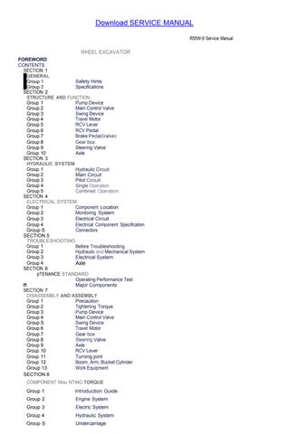
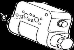
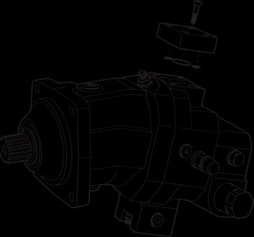
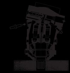
(4) Loosen the socket stud (1) and remove the pipe assy (2).
(5) Disconnect hoses (3,4,5).
(6) Loosen the hex bolt (6) and remove travel motor (7).
Weight :80 kg(180 lb)
※ When removing the travel motor assembly, check that all the hoses have been disconnected.
2) INSTALL
(1) Carry out installation in the reverse order to removal.
(2) Confirm the hydraulic oil level and check the hydraulic oil leak or not.
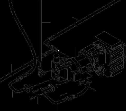
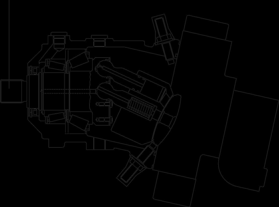
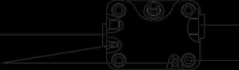
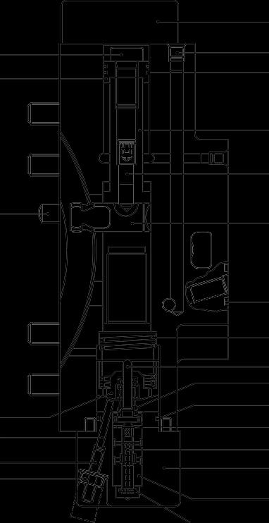
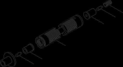
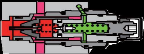
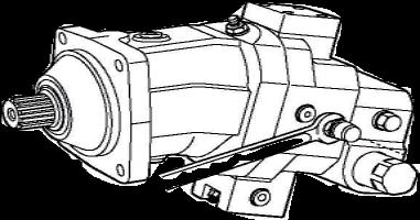
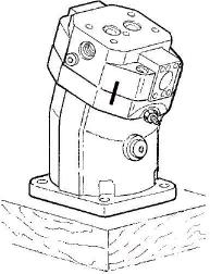
2. STRUCTURE
UNIT
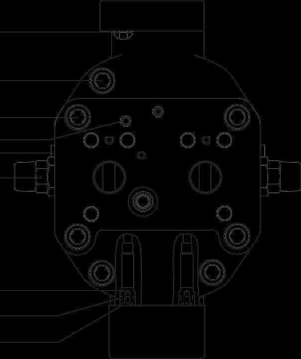
3.TIGHTENING TORQUE
The torques given are standard figures.Any figures specifically described in the procedure has priority.
4. DISASSEMBLY AND ASSEMBLY
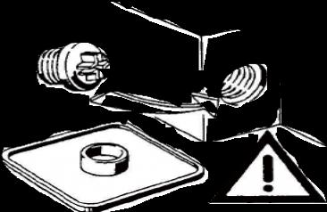
1) GENERAL PRECAUTIONS
(1) Disassembly
① Before disassembling the motor, check the items to be inspected and, for remedy against trouble, closely examine the nature of the trouble, so that the motor can be disassembled effectively.
Ⓒ To disassemble the motor, use the disassembling procedures described in section 2) and select a clean place.
③ Place a rubber or vinyl sheet or other such protective materials on your working bench to protect the surface of the motor to be serviced.
④ During disassembly, give a match mark to the mating surfaces of each part.
⑤ Arrange removed parts in order so that they will not become damaged or missing during disassembly.
⑥ Once seals have been disassembled, they should be replaced even if damage is not observed. Have replacement seals ready on hand before starting your disassembling job.
(2) Assembly
① Reassemble in a work area that is clean and free from dust and grit.
Ⓒ Handle parts with bare hands to keep them free of linty contaminants.
③ Repair or replace the damaged parts. Each parts must be free of burrs its corners.
④ Do not reuse O-ring oil seal and floating seal that were removed in disassembly. Provide the new parts.
⑤ Wash all parts thoroughly in a suitable solvent. Dry thoroughly with compressed air. Do not use the cloths.
⑥ When reassembling oil motor components of motor, be sure to coat the sliding parts of the motor and valve with fresh hydraulic oil.(NAS class 9 or above)
Ⓒ Use a torque wrench to tighten bolts and plugs, to the torque specified as follows.
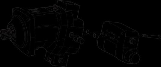
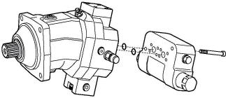
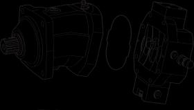
2) SEAL KITS AND COMPONENT GROUPS
Observe the following notices when carrying out repair work at hydraulic aggregates.
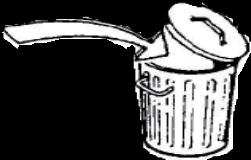
(1) Close all por ts of the hydraulic aggregates.
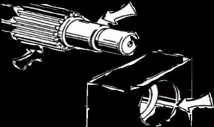
(2) Replace all seals. Use only original hydromatik spare parts.
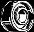
(3) Check all seal and sliding surfaces for wear.
※ Rework of sealing area f.ex. with abrasive paper can damage surface.
14W7TM007
14W7TM004
14W7TM005
14W7TM006
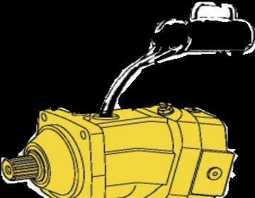
(4) Fill up hydraulic aggregates with hydraulic oil before start up.
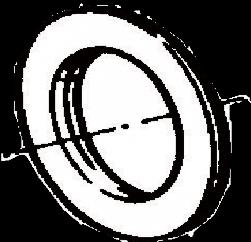
(6) External seal kit.
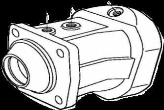
(7) Housing.
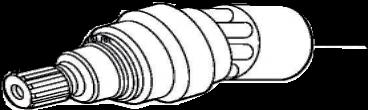
(5) Seal kit for drive shaft
14W7TM008
14W7TM009
14W7TM010
14W7TM011
(8) Complete rotary group.
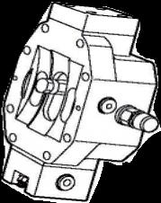
(9) Port plate with control piston.
(10)Counter balance valve.
(11)Relief valve / Make up check valve.
14W7TM014
14W7TM012
14W7TM013
14W7TM015
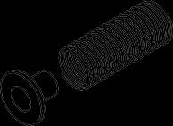
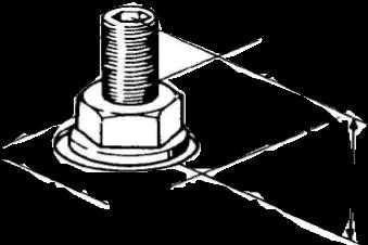
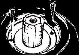
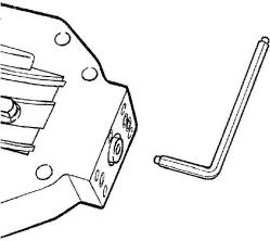
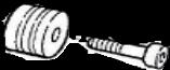
3) SEAL NUT
(1) Replace seal nut. First measure and record setting height.
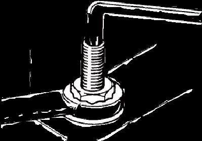
(2) When tightening, counterhold setting screw, then check setting height.
14W7TM016
14W7TM017
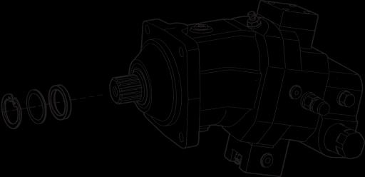
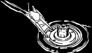
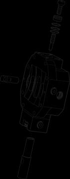
4) SEALING THE DRIVE SHAFT
(1) Protecting the drive shaft. Removeretainingring andshim.
(2) Screw in sheet metal screw into the holes fitted withrubber. Pull out seal with pliers.
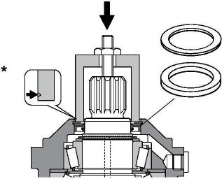
(3) Press in shaft seal and shim with bush to stop.
Pay attention to pressing depth.
* Mark for pressing depth. Assemble retaining ring.
14W7TM020
14W7TM019
20W78TO18
14W7TM021
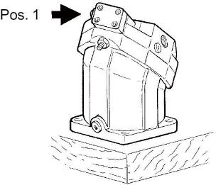
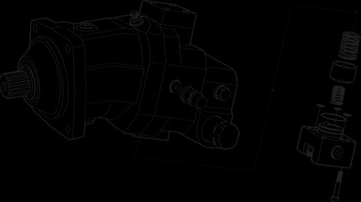
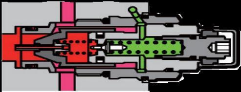
5) SEALING OF THE CONTROL PARTS
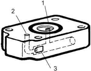
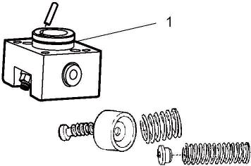
(1) Disassembly position
Remove cover 1.
1 O-ring
2 Input flow of oil control
3 Throttle pin
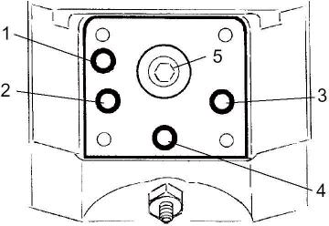
※ Installation position differs according to the control components.
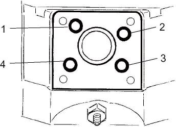
1 Input flow of oil control
2 High pressure / Low pressure
3 High pressure / Low pressure
4 Leakage oil
5 Control piston
14W7TM023
20W78TO22 14W7TM024
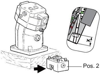
(2) Disassembly position : Remove cover 2.
※ Attentionspringload.
※ Dimension X :Note dimension (begin of regulation)
1 Check of O-ring
1 O-ring / High pressure-small control position side
2 O-ring / Control pressure
3 O-ring / High pressure-check valve
4 O-ring / High pressure-check valve
14W7TM027
20W78TO26
14W7TM028
14W7TM029
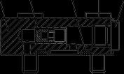
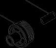
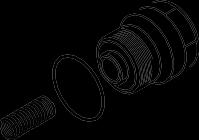
6) SEALING OF THE RELIEF VALVE / COUNTER BALANCE VALVE
Remove counter balance valve
Inspect O-ring
(1) Remove relief valve
(2) Inspect O-ring
(3) Removecounter-balancevalve.
Inspect O-ring
14W7TM031
14W7TM073
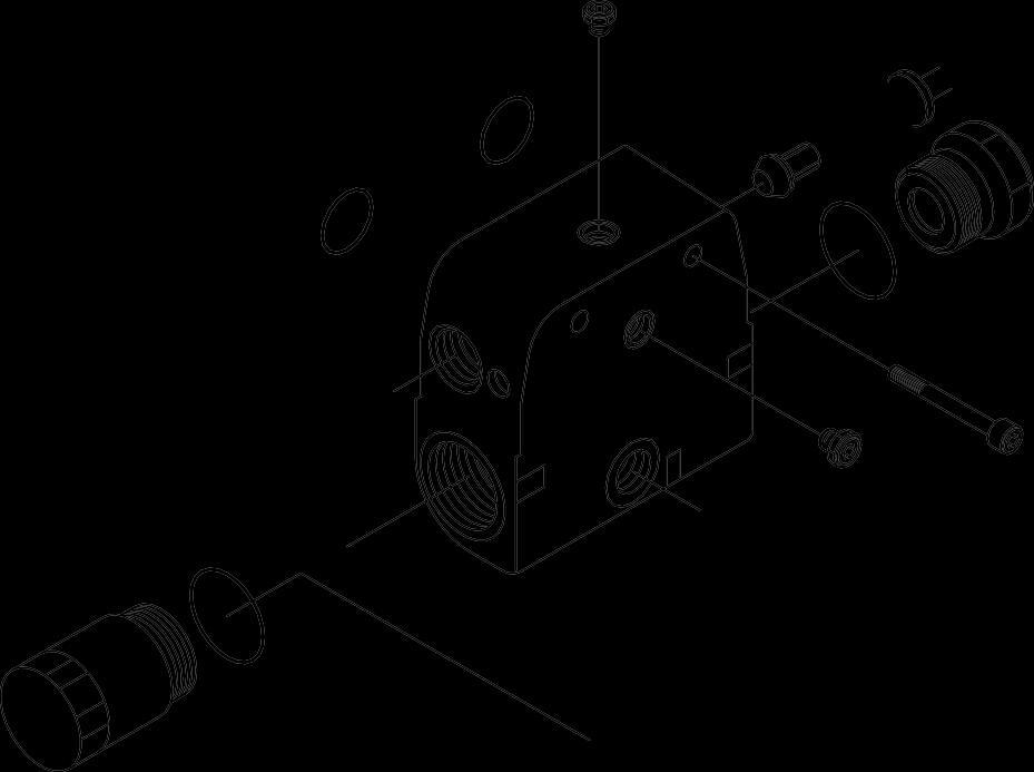
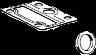
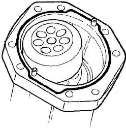
7) DISASSEMBLY OF THE PORT PLATE
Note dimension X Remove Qmin screw Swivel rotary group to zero P
(1) Port plate. Markposition. Loosen screws. Removal.
(2) Check O-ring.
※ SticknewO-ring withsomegrease. Do not swivel rotary group. Piston rings to hang out from the cylinder boring.
14W7TM039
14W7TM040
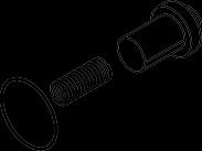
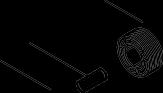
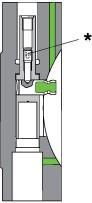
8) REMOVE OF THE POSITIONING PISTON
(1) Loosen fixing screw. Use only socketwrench.
(2) Remove piston with piston ring.
(3) Warm up fixation screw *for positioning plug viaboring(screw glued-toturnout).
※ Use new screw. Precode coating. Note tightening torque.
14W7TM042
20W78TO041
14W7TM043
14W7TM044