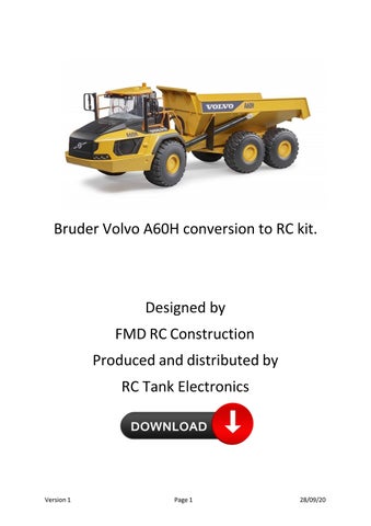

Bruder Volvo A60H conversion to RC kit.
Designed by
FMD RC Construction
Produced and distributed by
RC Tank Electronics

Skill Level
This conversion kit for the Bruder Vovlo A60H is recommended to users with medium and above competence.
The following instructions are deemed a guide to “how to do the conversion” not a concise step by step procedure.
Caution Note
• Carefully read and fully understand the instructions before commencing assembly. A supervising adult should also read and understand the instructions if a child assembles the model.
• When assembling this kit, tools including knives and heat gun are used. Extra care should always be taken to avoid personal injury and damage to the kit.
• All instructions relating to tools, glues, etc (not included in the kit) must be adhered to at all times.
• Keep out of reach of small children. Kit contains small parts and plastic bags which are harmful to children if swallowed.
Recommended Tools
• Philips screw driver
• Allen keys
• Hex socket
• HSS drill bits 2mm, 3mm, 3.5mm, 4mm, 5mm, 6mm, 10mm
• File
• Pliers
• Soldering Iron
• Side cutters
• Hot glue gun
• Knife
• G clamp (for pushing motors into 3D printed parts)
Parts not included in kit
• Servo double horn (60mm)
• Servo rod/stiff wire
• Heat shrink
• Glue
Parts List
Note depending on the kit purchased you may not have all the listed parts supplied.
Instructions
1. Disassemble Bruder model. (See Appendix A)
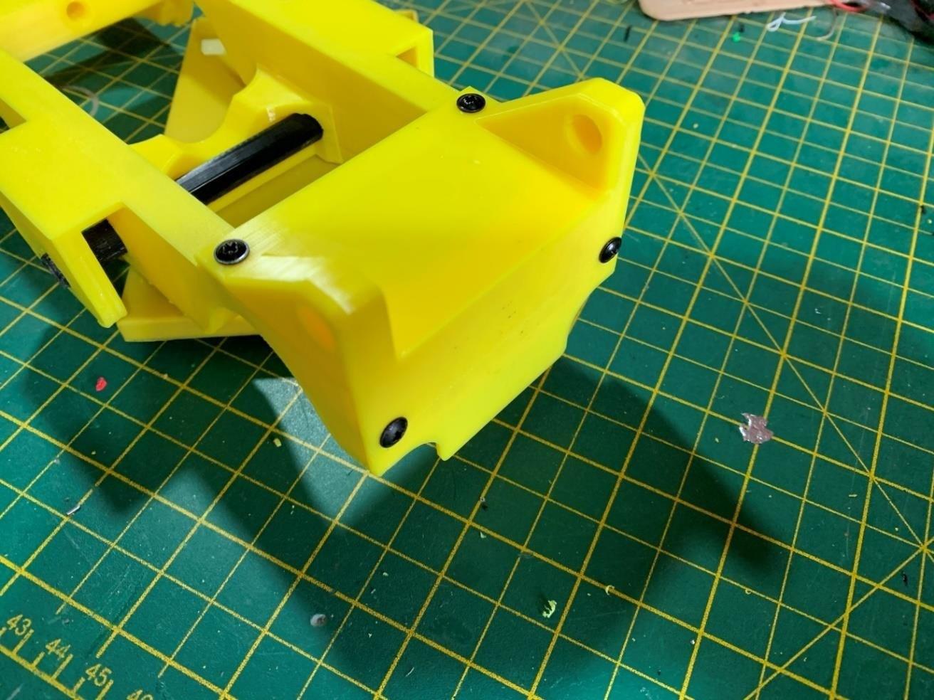
2. Cut front chassis to accept part number #A01.


3. Insert motors and steering servo into part number #A01. Secure each motor using 2no M3x8mm bolts. Note for easier access soldering on the cable to the motor terminals should be done before installing the motors.
4. Place the front axle (part number A#01) into the front chassis. Drill 4 fixing holes of 3.5mm diameter. Fix in place using M3x20mm bolts and nuts.


7. Install servo, servo horn and steering rods.

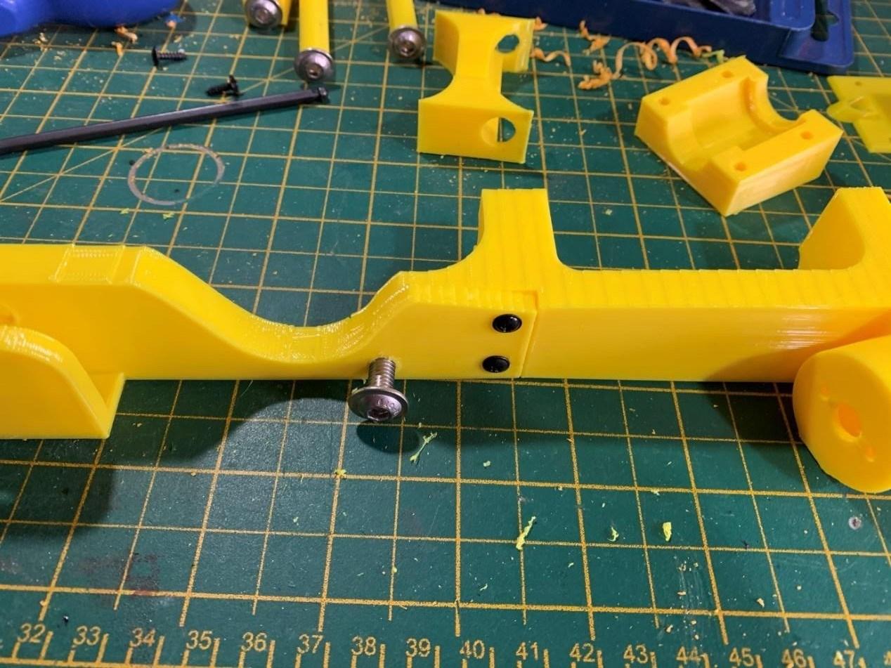
8. Place part numbers #A05 & #A07 together and upside down on a flat surface. Insert a M6 bolt through the large hole to hold in place. Drill the 2 smaller holes with a 2mm drill bit, 12mm deep. Use 2 self tapping screws to hold together.
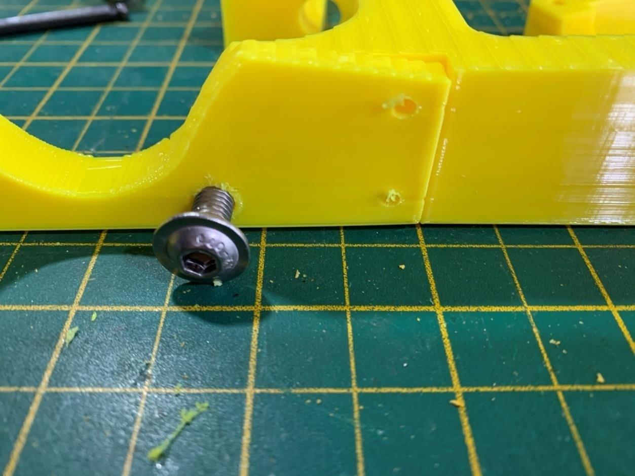
9. Do the same for parts #A06 & #A08.
10. Screw the M6 x16mm bolts into part #A09, M6x30mm bolts into parts #A09A and #A12. Make sure the bolts are square when put in. This action will form a thread ready for later installation process.

11. Place the 2 parts from step 8 & 9 above together, position part number #A09 between them (note flat edge to top). Using M6 x 30mm bolts fix through the chassis side into part number #A09 and repeat from other side.

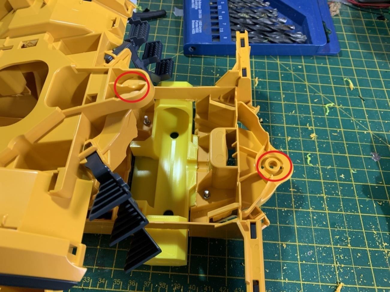
12. Position part number #A09A as shown, glue in place. Part number #A10 can be inserted to aid correct alignment.

13. Position part number #A11 at the rear of the chassis. Using 2mm drill bit, drill pilot holes 12mm deep into the chassis at the top and back. Secure with glue and 4 self tapping screws.

14. Insert the lift motors into the openings. Soldering the wires to the motor before hand is mandatory as you wont have clear access later. The fit is tight, so the using of a press or G clamp will assist in pushing in the motors.


15. Make sure the fixing holes line up with the motor when pushing in and fix in place with 2 x m3 x 8mm bolts
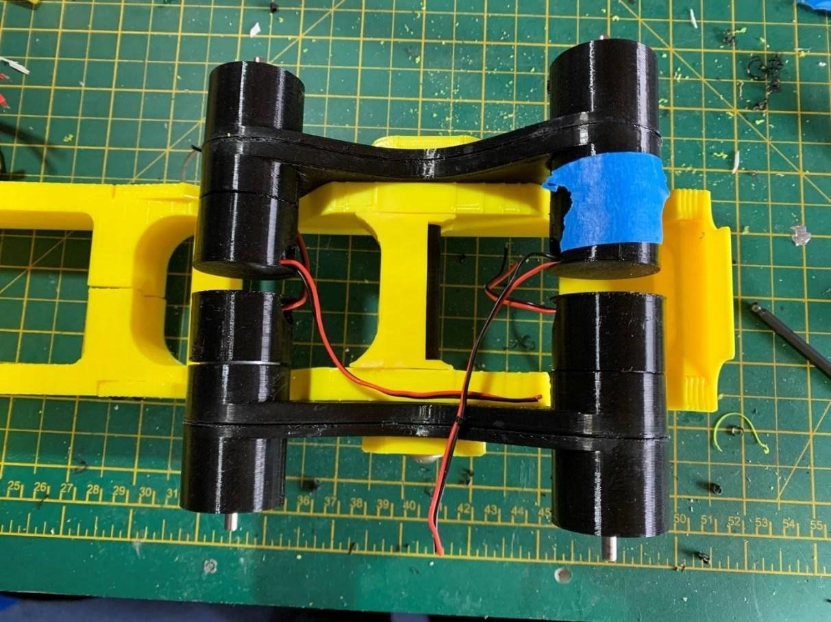
16. Glue part #A13 and #A14 together x2. Clamp or tape together whilst the glue sets. Note inserting the motors will aid alignment of the parts.


17. Place the motors into part number #A13/14 (2No). Secure each motor using 2no M3x8mm bolts. Note for easier access soldering on the cable to the motor terminals should be done before installing the motors. Note polarity needs swapping on one side of the vehicle.

18. Add part number #A15 to the back of each rear motor. Hold in place with a dab of hot glue. Note adding identification to the side which is wired with reversed polarity to aid correct wiring later.

19. Position the 2 No part number #A13/14 into the chassis so the drive shafts face outwards. Hold in place with part number #A09A & #A10. Secure in place with M6 x 30mm bolt each side.

20. Turn the chassis upside down. Position the front half of the truck so to place part number #A02 at the front and place part number #A04 over it. Hold in place and turn over, and place part #A03 on top and secure with M3x25mm bolts.
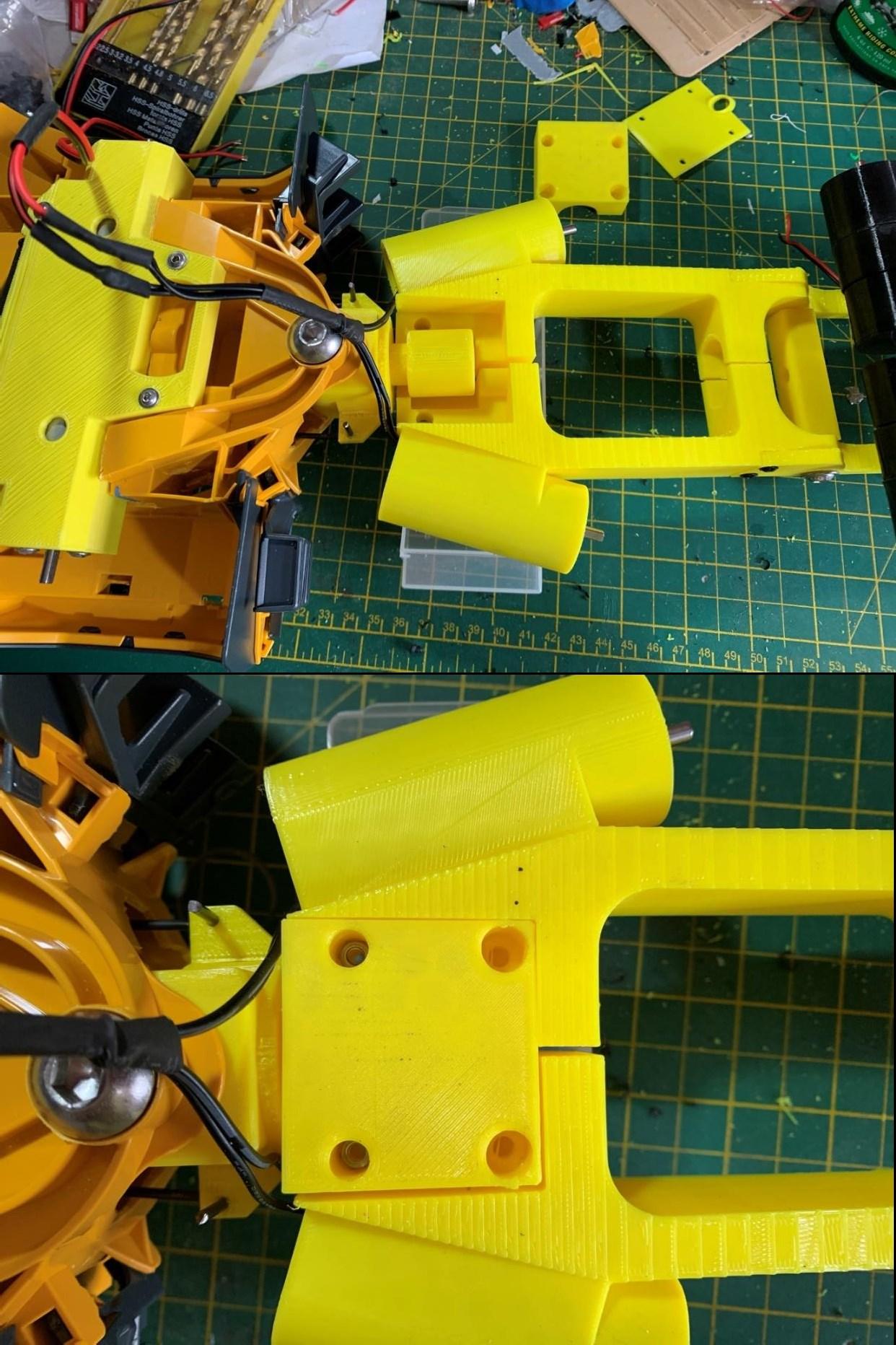

Then using a 2mm drill bit, drill pilot holes through part #A04 and secure with self tapping screws.

Then using a 2mm drill bit, drill pilot holes at the back of the cover plate and secure with self tapping screws.

21. Glue the lift nut into part number #A17, drill 2mm pilot holes and attach with self tapping screws. For both parts.


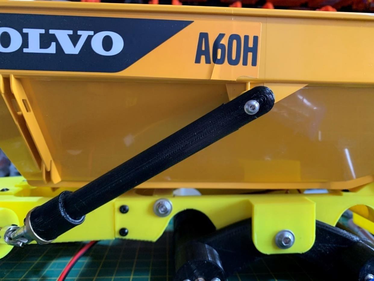
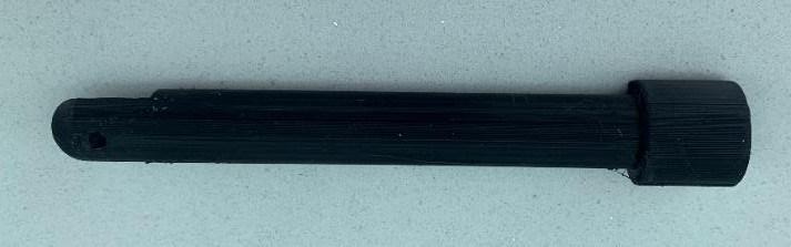
22. Grind down one end of the T8 lead screw to 6mm diameter and attach to the motor coupler. Also cut down to the required length. (Approx. 12cm)
Attach the 4-6mm universal coupler to the motor shaft using the 4mm side.


23. Attach the universal coupler to the lift motor shaft and tighten the grub screw.

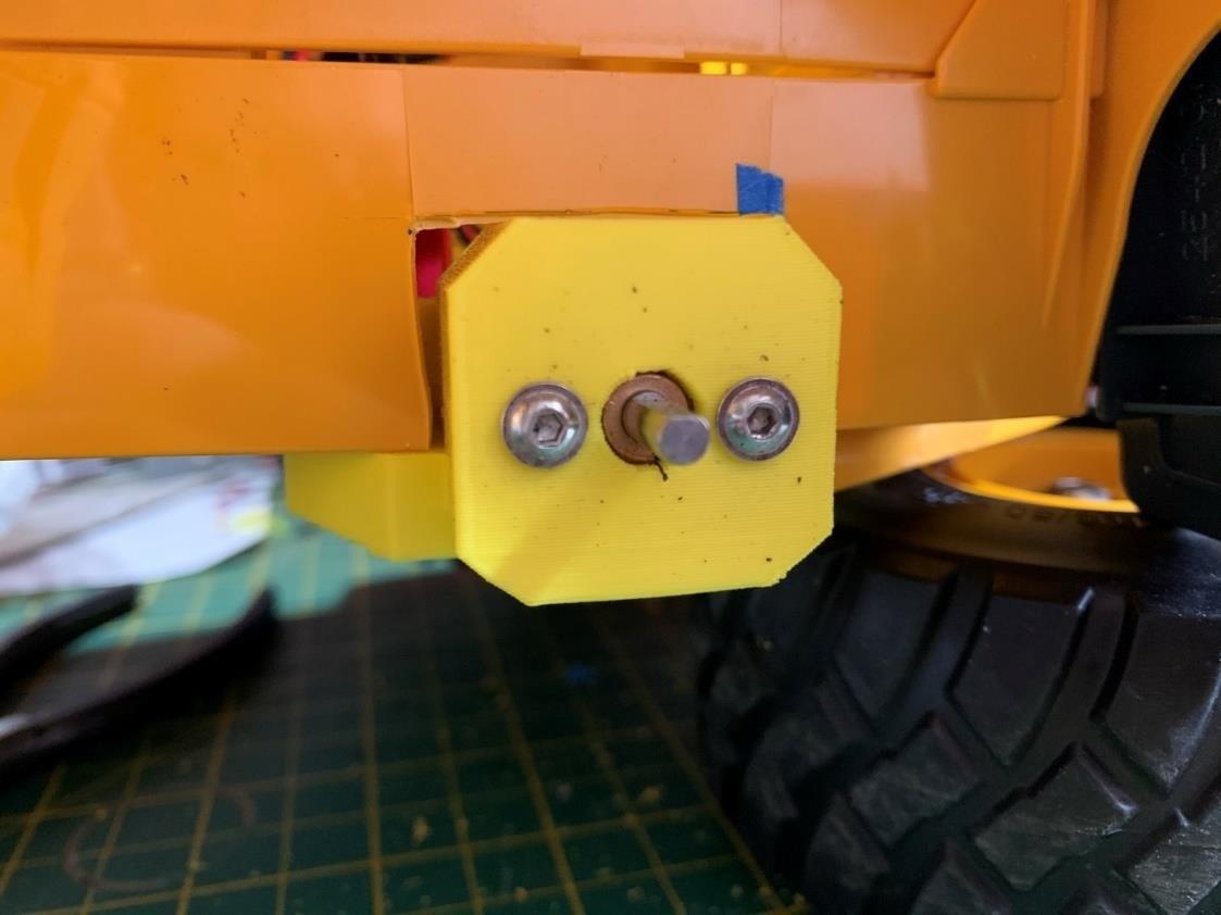
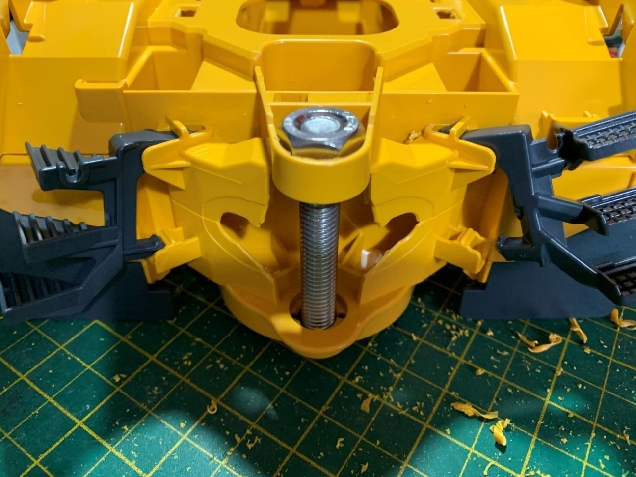
24. Add the Bruder dump body to the hinge and secure using a M6x30mm bolt in each side into part #A12.

25. Add the T8 lead screw nut and part #A17, wind down to the motor end.
26. Attached part number #A17 to the dump body bracket using M3 x 20nn bolt and nut. Note Don’t over tighten as the joint needs a little flexibility.
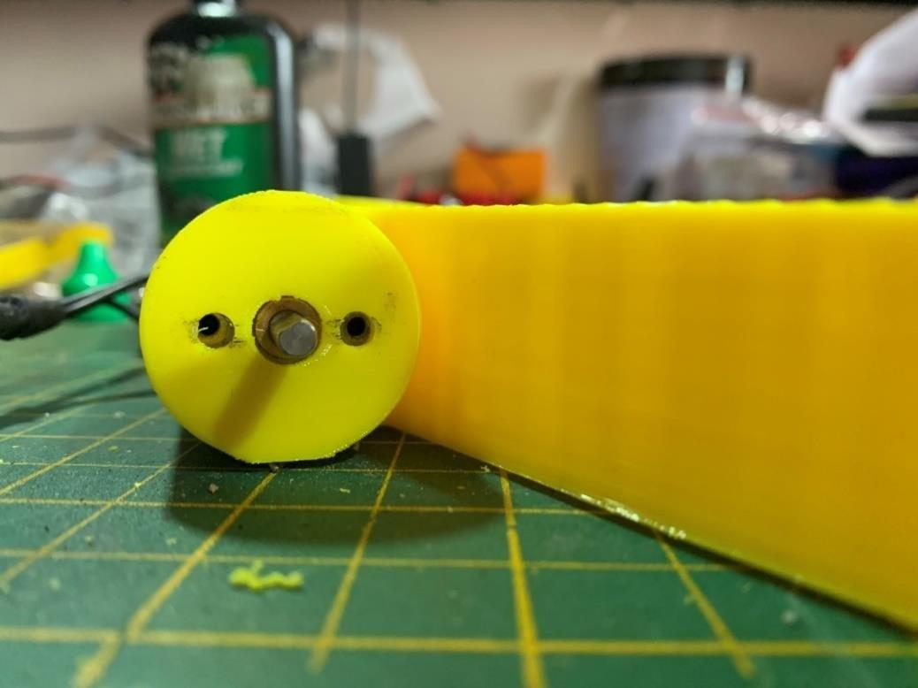
27. Part number #A16 (6No) screw in the 2 x M3x12mm bolt but don’t block the shaft opening.

28. Drill 5mm hole in the Bruder wheel from the inside tube (this allows for perfect centering of the hole)

Cut away the internal plastic to leave a flat surface on the inside. Now enlarge the hole with a 6mm drill bit.

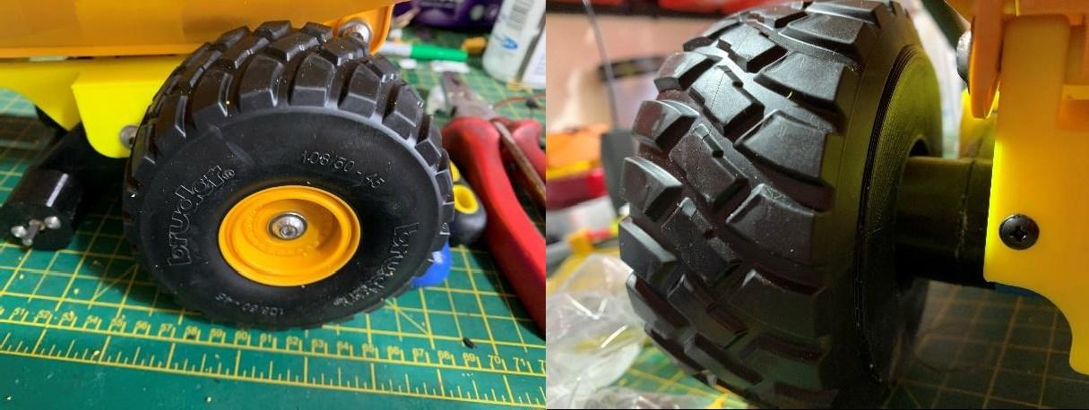
29. Push part number #A16 onto the 6 motor shafts noting the flat side on the shaft needs to align with one of the M3 bolt mentioned in above. Once pushed on, tighten the bolt opposite the shaft flat first then tighten the bolt on the shaft flat side, this helps keep the wheel square on the shaft.
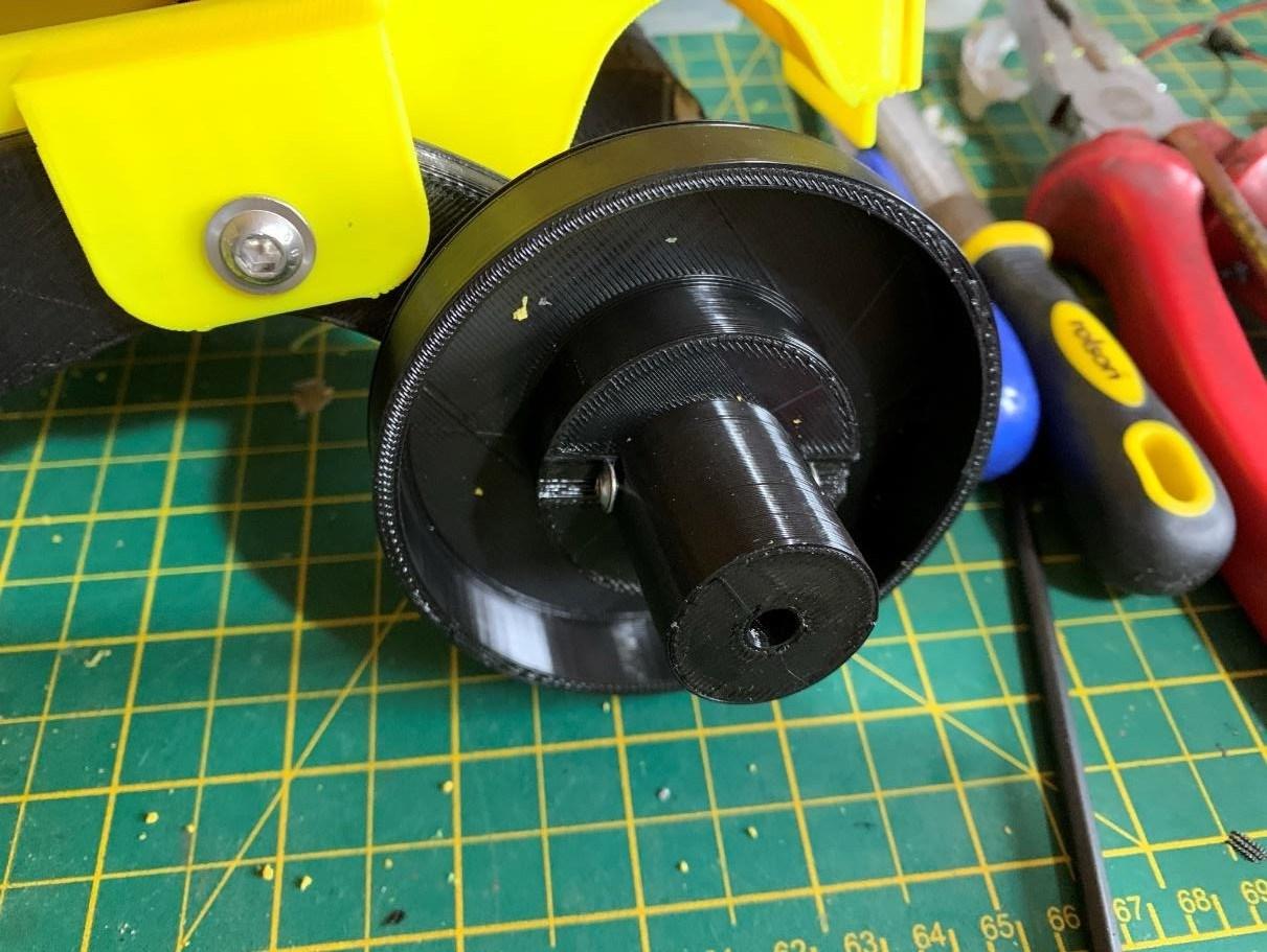
30. Using M6x16mm bolt attached Bruder wheel over supplied re-enforced wheel. Repeat for all 6 wheels.
31. Feed motor wires through the cable holes in the chassis back to the front cab.
32. Install battery, ESC’s, receiver and connect up to the motors and receiver.
33. Test operation.
Controls (RTR version)
Left stick up/down
Drive forward/reverse
Right stick up/down Bucket tilt up/down
Right stick left/right Steer left/right
Switch A Lights if installed
Switch D Orange beacon if installed
Notes
• If sound unit is installed the sound will automatically start when drive forward/reverse is activated, engine sound will idle for 15 seconds then stop if no further input is detected.
• If orange beacon is installed, when powered on the unit will do fast rotation effect, to cycle through different effects move switch D down then up to move along one sequence. Sequences are Fast rotation
Slow rotation
Fast flash Slow flash Off
• There are no limit switches on the bucket lift or lower. DON’T keep going down when already down. Going to far up will cause the lift rods to unscrew.
Dismantling the Bruder model can be difficult as are bult not to come apart as intended for 3 year + children. The following is given to assist in the dismantling of the model ready to be modified for the conversion.
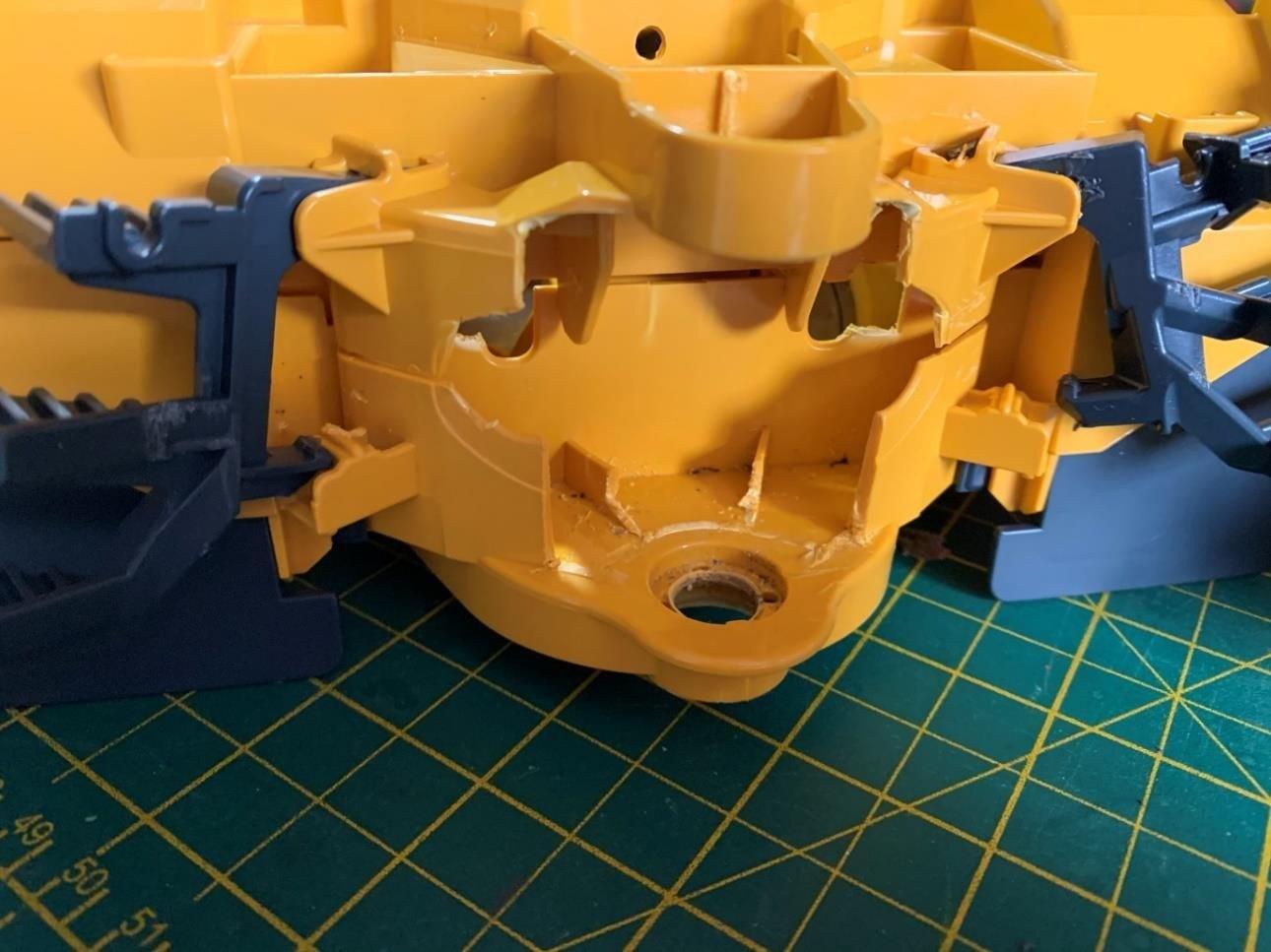
Remove the dump tub plastic cylinders. A flat headed screwdriver or similar can be used to prise the cylinder from the dump tub. It’s not necessary to remove the end attached to the chassis but can be for easier access later on removing the wheels.

Remove the dump tub by prising the lugs over the hinge.
Remove the lower part of the access ladders to the cab the front to rear umbilical attachment.
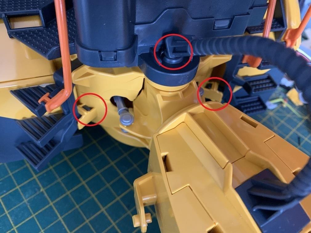
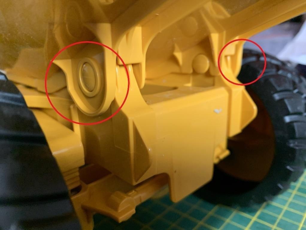
Turn upside down and release or snap off the 7 clips under the cab. You should now be able to separate the front lower and top section which will also disconnect the rear chassis.

Separate the front middle and top section by releasing the indicated clips.

To remove the wheels from the metal axle. 2 options.
1. Brute force hold one wheel in a vice or something and pull on the other. Note considerable force is needed so be careful not to injure yourself, others or property.
2. Using a sharp knife cut a slot down the plastic wheel shaft, then twist the wheel and it should come away from the shaft.


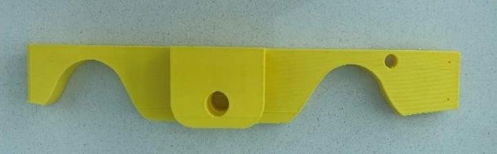
Part number #A01
Description Front axle
Quantity 1

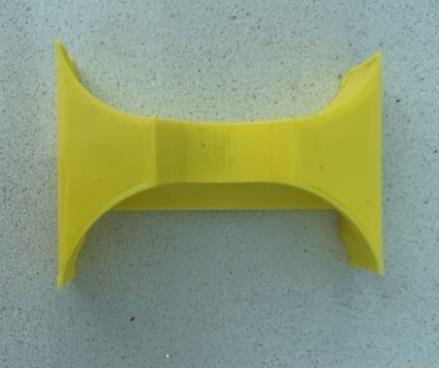
Part number #A02
Description Swivel
Quantity 1

Part number #A03
Description Chassis plate
Quantity 1

Part number #A04
Description Swivel Cover
Quantity 1
Part number #A05
Description Chassis a
Description 1

Part number #A06
Description Chassis b
Description 1
Part number #A07
Description Chassis c
Description 1
Part number #A08
Description Chassis d
Description 1
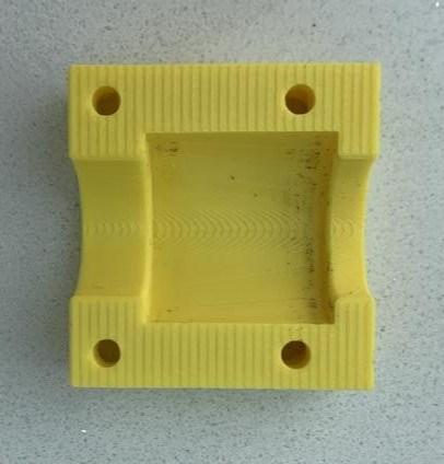
Part number #A09
Description Chassis cross brace
Description 1
Part number #A09a
Description Chassis cross brace
Description 1

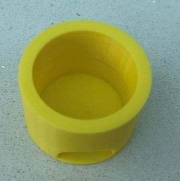
Part number #A10
Description Axle sleeve
Description 1

Part number #A11
Description Dump hinge bracket
Description 1

Part number #A12
Description Hinge sleeve
Description 2
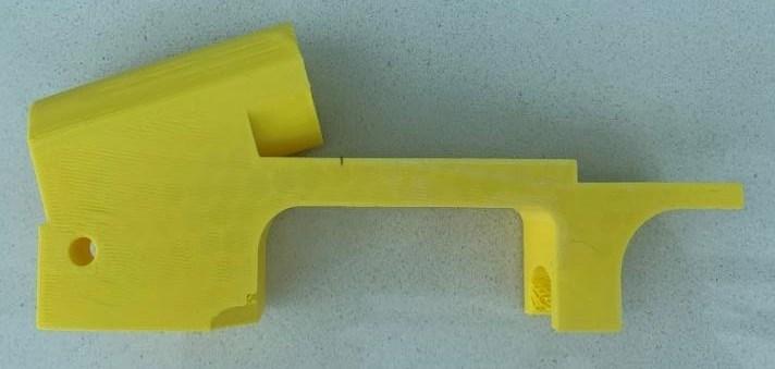
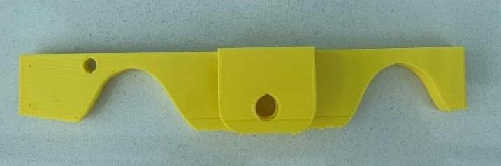
Part number #A13
Description Rear axle arm a
Description 2


Part number #A14
Description Rear axle arm b
Description 2

Part number #A15
Description Motor caps
Description 4
Part number #A16
Description Wheel Complete
Description 6

Part number #A17
Description Piston Arms
Description 2
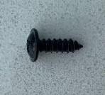
Part number #B01
Description Self tapping screw
Description 10
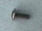
Part number #B02
Description M3 x 12mm motor shaft bolt
Description 12
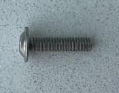
Part number #B03
Description M3 x 8mm motor bolt
Description 16
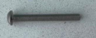
Part number #B04
Description M6 x 30 Rear axle & hinge bolt
Description 5
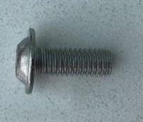
Part number #B05
Description M6 x 16 Wheel to hub bolt
Description 6
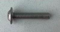
Part number #B06
Description M3 x 20 Front axle fixing bolt
Description 4
Part number #B07
Description M3 x 20 Swivel cover bolt
Description 2
Part number #B08
Description M3 nut
Description 6
Part number #B09


Description M10 x 65mm Swivel nut and bolt
Description 1