
SHOP MANUAL CASE/INTERNATIONAL
MODELS 5120, 5130 & 5140
IDENTIFICATION
Tractor modelnumber andidentificationseriai numberare located on a plate on lower ieft side of instrument panel cover on tractors equipped with a cab or lower ieft front side of operator's platform on tractors equipped with a ROPS frame Engine seriai number is located on a plate on left side of timing gear housing. Transmission seriai number is located ona plate on right side of transmission housing. On models equipped with mechanical frontwheel-drive axle, the axie seriai number is located on a plate on right rear side of front axle housing.
INDEX (By Starting Paragraph)
INDEX (CONT.)
INDEX (CONT.)
INDEX (CONT.)
RANGE TRANSMISSION &FORWARDREVERSE SHUTTLE TRANSMISSION Inching Pedal & Transmission
Adjustment
Shuttle Valve
and Overhaul
Displacement
CONDENSED SERVICE DATA
(4.72 in.) (4.72 in.)
L (239 cu. in.) (359 cu. in.) Compression
TUNE-UP
(0.010 in.)
mm (0.020 in.)
Injection Timing Paragraph 61 Paragraph 60
Injector Opening Pressure 24,500-25,305 kPa (3553-3670 psi) Engine Low Idle
(4.02 in.)
(4.72 in.)
L (359 cu in.)
Paragraph 61
CONDENSED SERVICE DATA (CONT.)
Models
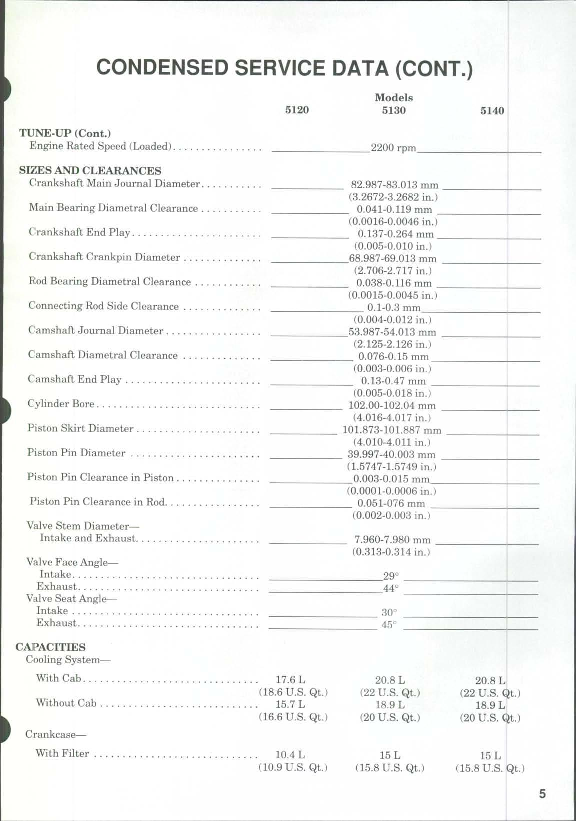
TUNE-UP (Cont.)
Engine Rated Speed (Loaded)
SIZES AND CLEARANCES
Crankshaft Main Journal Diameter
Main Bearing Diametral Clearance
C!rankshaft End Play
Crankshaft Crankpin Diameter
Rod Bearing Diametral Clearance
Connecting Rod Side Clearance
Ciamshaft Journal Diameter
Camshaft Diametral Clearance
Camshaft End Play
Cylinder Bore
Piston Skirt Diameter
Piston Pin Diameter
Piston Pin Clearance in Piston
Piston Pin Clearance in Rod
Valve Stem Diameter Intake and Exhaust
Valve Face Angle Intake Exhaust
Valve Seat Angle Intake Exhaust
CAPACITIES
Cooling System
With Cab Without Cab
Crankcase With Filter
2200 rpm
82.987-83.013 mm
(3.2672-3.2682 in.)
0.041-0.119 mm
(0.0016-0.0046 in.)
0.137-0.264 mm
(0.005-0.010 in.)
68.987-69.013 mm
(2.706-2.717 in.)
0.038-0.116 mm
(0.0015-0.0045 in.)
0-1-0.3 mm
(0.004-0.012 in.)
53.987-54.013 mm
(2.125-2.126 in.)
0.076-0.15 mm
(0.003-0.006 in.)
0.13-0.47 mm
(0.005-0.018 in.)
102.00-102.04 mm
(4.016-4.017 in.)
101.873-101.887 mm
(4.010-4.011 in.)
39.997-40.003 mm
(1.5747-1.5749 in.)
0.003-0.015 mm
(0.0001-0.0006 in.)
0.051-076 mm
(0.002-0.003 in.)
7.960-7.980 mm
(0.313-0.314 in.)
CONDENSED SERVICE DATA (CONT.)
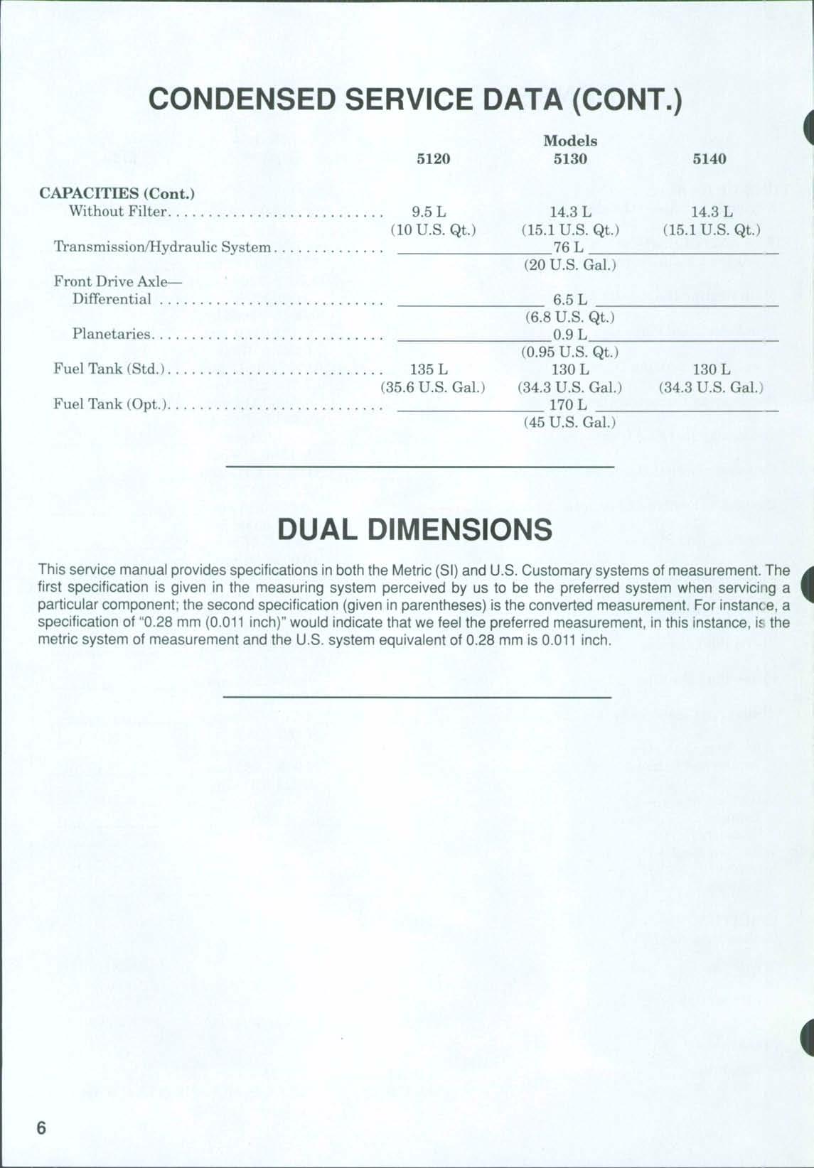
(Cont.)
DUAL DIMENSIONS
This service manual provides specifications in both the Metric (SI) and U.S Customary systems of measurement The first specification is given in the measuring systenn perceived tDyus to be the preferred system when servicing a particular component; the second specification (given inparentheses) isthe converted measurement. Forinstanc e,a specification of "0.28 mm (0.011 inch)" would indicate that we feel thepreferred measurement, inthis instance, is the metric system of measurement and the U.S system equivalent of 0.28 mm is 0.011 inch
FRONT AXLE (TWO-WHEEL DRIVE)
FRONT WHEEL BEARINGS
All Models
1 Refer to Fig 1 for typical wheel hub and bearing assembly.
The tapered inner and outer roller bearings (4 and 10) are not interchangeable Clean and inspect bearing cups and cones and renev^ as necessary.
Install inner bearing cone (4) on steering knuckle spindle Install bearing cups (5 and 9) in hub Install oil seal (3) and clamping ring (2) in inner bore of hub Pack bearing cones and fill hub with No 2 lithium base grease. Install hub on steering knuckle, then install outer bearing cone (10), washer (11) and nut (12;'
TD adjust the bearings, tighten nut to a torque of 100 N.m (74 ft.-lbs.) while rotating the hub. Then, back nut off until next cotter pin slot is aligned. Install cotter pin Install and tighten dust cover (13)
Install wheel and tire, and tighten lug nuts (8)to a torque of 300 N.m (220 ft. lbs.).
STEERING KNUCKLES
All models
2.REMOVEAND REINSTALL. To remove either steering knuckle, raise front of tractor and place a stand under axle extension. Remove wheel and tire assembly. Disconnect tie rod ball joint from steering arm (8—Fig 2) and steering cylinder ball joint (13) from right steering arm Support hub and steering knuckle and remove steering arm clamping bolt. Lift off steering arm and shims (9). Lower steering knuckle from axle extension (12)
Remove felt seal (10) and upper bushing (11) from axle extension. Remove lower bushing (17) and thrust bearing (18) from steering knuckle. Split bushings (11 and 17) are not a tight fit in axle extensions If necessary, remove hub and wheel bearings as outlined in paragraph 1
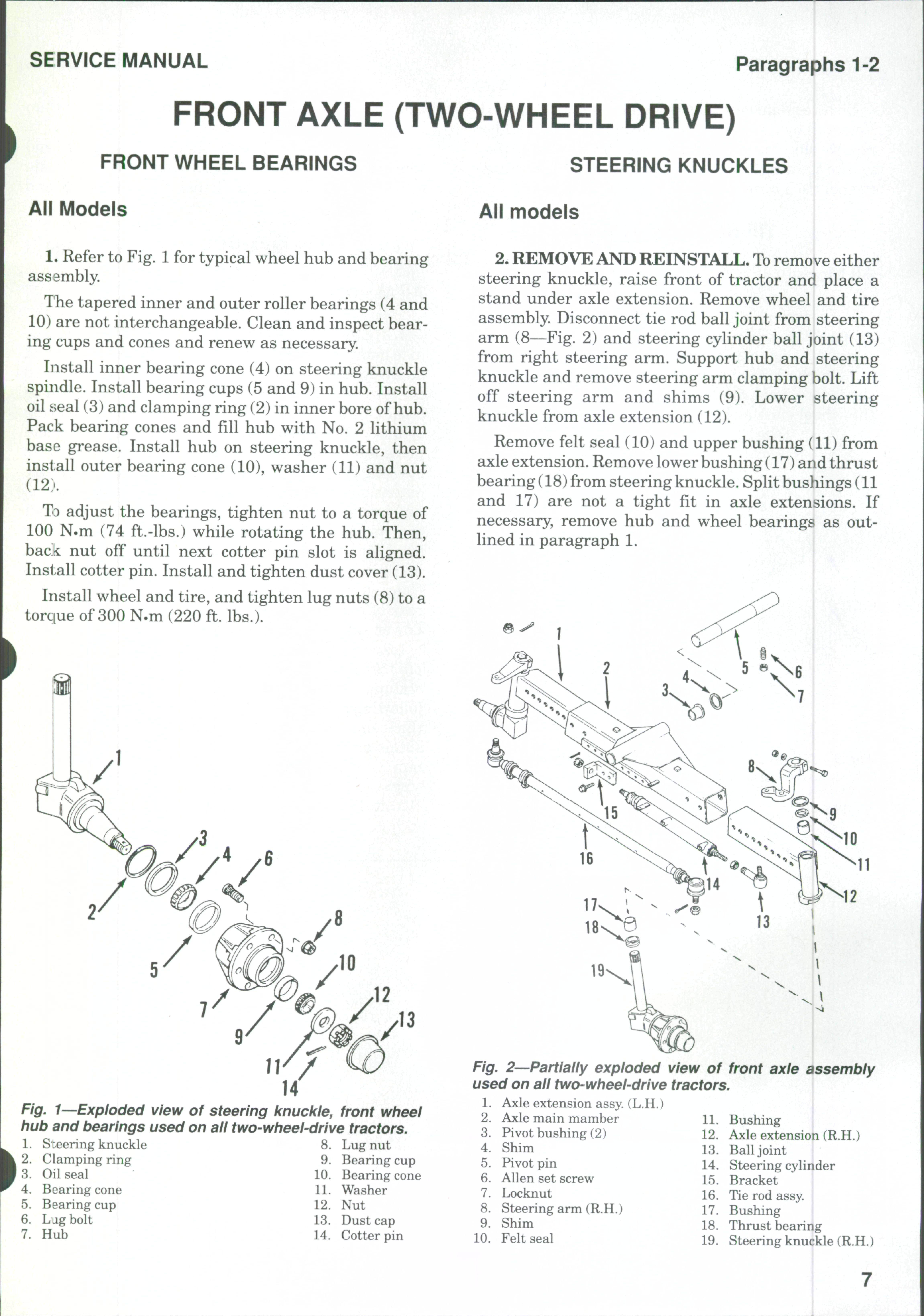
1—Exploded view of steering knuckle, front wheel hub and bearings used on all two-wheel-drive tractors.
S:eering knuckle
Clamping ring
Oil seal
Bearing cone
Fig. 2 Partially exploded view of used on all two-wheel-drive tractors
1 Axle extension assy (L.H.)
2 Axle main mamber 11
3 Pivot bushing (2) 12
4. Shim 13.
5 Pivot pin 14,
6 Allen set screw 15
7 Locknut 16
8. Steering arm (R.H.) 17.
9 Shim 18
10 Felt seal 19
front axle assembly
Bushing Axle extension (R.H.)
Ball joint
Steering cylinder
Bracket
Tie rod assy.
Bushing
Thrust bearing
Steering knuckle (R.H.)
Fig.
Paragraphs 3-4
Clean and inspect all parts and renew as required Reinstall by reversing the removal procedure Add or remove shims (9) to obtain 0.1mm (0.004in.)end play for the steering knuckle Tighten steering arm clamping bolt to a torque of 280 N.m (206 ft.-lbs.)
TIE ROD AND TOE-IN
All Models
3. Disassembly of the tie rod is obvious after an examination of the unit and reference to Fig 3
Front wheel toe-in should be 2-4 mm (0.080-0.160 in.) To check toe-in, measure the distance between the front wheel rims at the front and at the rear of the wheel rims at hub height The measurement at
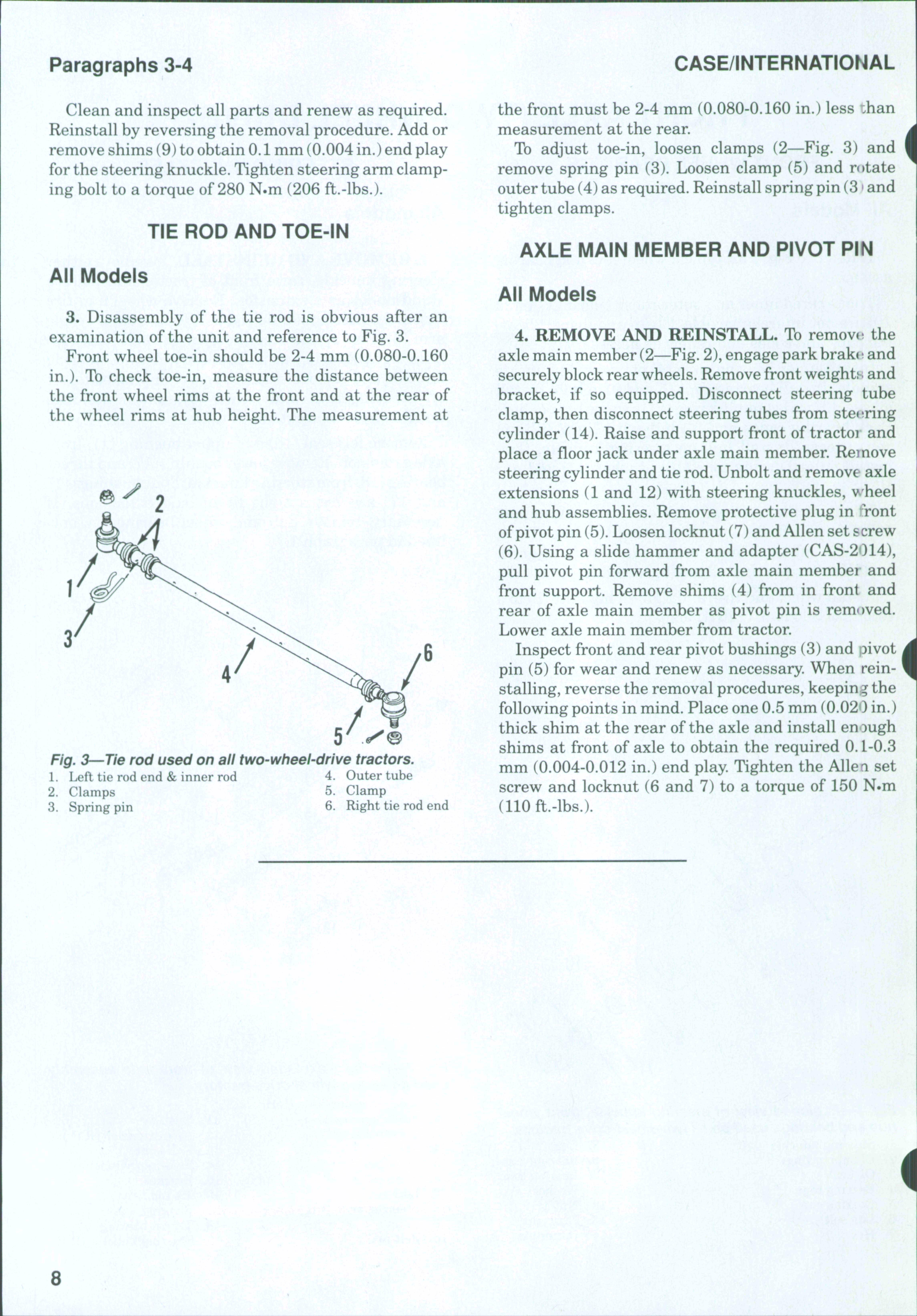
Fig. 3—Tie rod used on all two-wheel-drive tractors.
1 Left tie rod end & inner rod
4 Outer tube
2 Clamps 5 Clamp
3 Spring pin
6 Right tie rod end
the front must be 2-4 mm (0.080-0.160 in.) less ihan measurement at the rear
To adjust toe-in, loosen clamps (2—Fig 3) and remove spring pin (3) Loosen clamp (5) and r(»tate outer tube (4) as required Reinstall spring pin (3 • and tighten clamps.
AXLE MAIN MEMBER AND PIVOT PIN
All Models
4. REMOVE AND REINSTALL. To remove the axle main member (2—Fig 2),engage park brake and securely blockrear wheels Remove front weights and bracket, if so equipped. Disconnect steering tube clamp, then disconnect steering tubes from steering cylinder (14). Raise and support front of tractor and place a floor jack under axle main member. Remove steering cylinder and tie rod. Unbolt and remove axle extensions (1 and 12) with steering knuckles, wheel and hub assemblies. Remove protective plug in *Tont ofpivot pin (5) Loosen locknut (7) and Allen set screw (6) Using a slide hammer and adapter (CAS-2014), pull pivot pin forward from axle main member and front support Remove shims (4) from in front and rear of axle main member as pivot pin is rem<»ved Lower axle main member from tractor Inspect front and rear pivot bushings (3) and pivot pin (5) for wear and renew as necessary. When reinstalling, reverse the removal procedures, keeping the following points in mind. Place one 0.5 mm (0.020 in.) thick shim at the rear of the axle and install enough shims at front of axle to obtain the required 0. L-0.3 mm (0.004-0.012 in.) end play Tighten the Allen set screw and locknut (6 and 7) to a torque of 150 N.m (110 ft.-lbs.)
FRONT DRIVE AXLE
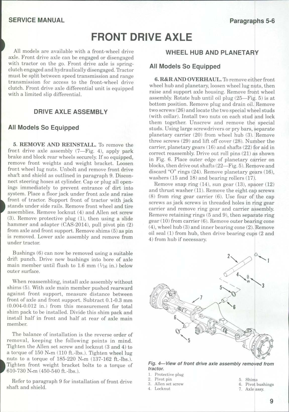
All models are available with a front-wheel drive axle. Front drive axle can be engaged or disengaged with tractor on the go. Front drive axle is springclutch engaged and hydraulically disengaged TVactor must be split between speed transmission and range transmission for access to the front-wheel drive clutch. Front drive axle differential unit is equipped witli a limited slip differential.
DRIVE AXLE ASSEMBLY
All Models So Equipped
5 REMOVE AND REINSTALL. To remove the frort drive axle assembly (7—Fig. 4), apply park bra]i:e and block rear wheels securely. If so equipped, remove front weights and weight bracket Loosen front wheel lug nuts Unbolt and remove front drive shaft and shield as outlined in paragraph 9. Disconnect steering hoses at cylinder. Cap or plug all openings immediately to prevent entrance of dirt into system Place a fioor jack under front axle and raise front of tractor Support front of tractor with jack I stands under side rails. Remove front wheel and tire assemblies. Remove locknut (4) and Allen set screw (3) Remove protective plug (1), then using a slide hammer and adapter (CAS-2014), pull pivot pin (2) from axle and front support Remove shims (5) as pin is removed. Lower axle assembly and remove from under tractor.
Bushings (6) can now be removed using a suitable drift punch. Drive new bushings into bore of axle main member until fiush to 1.6 mm (Vi6 in.) below outeir surface.
When reassembling, install axle assembly without shims (5) With axle main member pushed rearward against front support, measure distance between front of axle and front support Subtract 0.1-0.3 mm (0.004-0.012 in.) from this measurement for total shim pack to be installed. Divide this shim pack and install half in front and half at rear of axle main member
Tlie balance of installation is the reverse order of removal, keeping the following points in mind Tighten the Allen set screw and locknut (3 and 4) to a torque of 150 N.m (110 ft.-lbs.) Tighten wheel lug nuts to a torque of 185-220 N.m (137-162 ft.-lbs.). I Tighten front weight bracket bolts to a torque of 610-730 N.m (450-540 ft.-lbs.)
Refer to paragraph 9 for installation of front drive shaft and shield.
WHEEL HUB AND PLANETARY
All Models So Equipped
6. R&RAND OVERHAUL.To remove either front wheel hub and planetary, loosen wheel lug nuts, then raise and support axle housing Remove front wheel assembly. Rotate hub until oil plug (25—Fig. 5) is at bottom position. Remove plug and drain oil. Remove two screws (26)and locate the two special wheel studs (with collar) Install two nuts on each stud and lock them together Unscrew and remove the special studs. Using large screwdrivers or pry bars, separate planetary carrier (20) from wheel hub (3). Remove three screws (29) and lift off cover (28) Number the carrier, planetary gears (16) and shafts (22) for aid in correct reassembly Drive out roll pins (21) as shown in Fig. 6. Place outer edge of planetary carrier on blocks,then drive out shafts (22—Fig.5).Remove and discard "O" rings (24) Remove planetary gears (16), washers (15 and 18) and bearing rollers (17)
Remove snap ring (14), sun gear (13), spacer (12) and thrust washer (11). Remove the eight cap screws (8) from ring gear carrier (6) Use four of the cap screws as jack screws in threaded holes in ring gear carrier and remove ring gear and carrier assembly Remove retaining rings (5 and 9), then separ'ate ring gear (10) from carrier (6). Remove outer bearing cone (4), wheel hub (3) and inner bearing cone (2) Remove oil seal (1) from hub, then drive bearing cups (2 and 4) from hub if necessary I
Fig. 4—View of front drive axle assembly removed from tractor.
Paragraph 7
Clean and inspect all parts and renew any showing excessive wear or other damage. Reinstall by reversing removal procedures keeping the following points in mind: Use new oil seal (1) and "0" rings (24). Tighten ring gear carrier cap screws (8) to a torque of 200 N.m (162 ft.-lbs.). When installing planetary carrier (20) on wheel hub (3), apply Activator (CAS345153) to face of planetary carrier and Sealant (CAS-345152) to face of hub. Within five minutes after assembly, tighten the two special wheel studs to a torque of 70 N.m (51 ft.-lbs.) and the two countersunk screws (26) to a torque of 80 N.m (59 ft.-lbs.) Install cover (28) and tighten the three screws (29) to a torque of 34 N.m (25 ft.-lbs.)
Rotate hub until the word CASE is horizontal, then fill the unit to level plug opening with SAE 85W-140 gear lubricant Capacity is approximately 1.0 liter (1.06 U.S. qt.). Install plug (25). Install wheel and tighten lug nuts to 300 N.m (220 ft.-lbs.) torque
Repeat operation on opposite wheel hub and planetary if necessary
PIVOT HOUSING AND AXLE SHAFT
All Models So Equipped
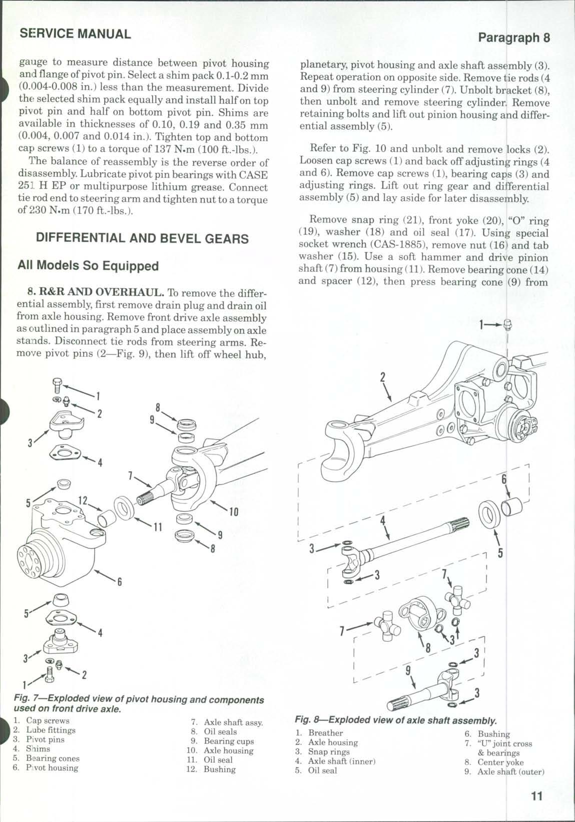
7. REMOVE AND REINSTALL. To removt the pivot housing (6—Fig. 7), first remove the wheel hub and planetary as outlined in paragraph 6. Disconnect tie rod end from steering arm. Remove cap screws (1), then remove pivot pins (3)with shims (4) and bearing cones (5) Lift off pivot housing (6) Remove oil seal (11) and, if necessary, remove bushing (12)from pivot housing Remove oil seals (8) and bearing cups (9) Use a suitable puller toremove bearing cones(5) from pivot pins
Withdraw axle shaft assembly (7) Remove oil seal (5—Fig 8) and, if necessary, remove bushing (6
Clean and inspect all parts and renew any showing excessive wear or other damage. "U" joint cross and bearings (7) are available only as a unit. Renev al of "U"joints is obvious after examination of the assembly and reference to Fig. 8.
When reassembling, use all new oil seals Install seal (5—Fig 8) in axle housing (2), then care fully install axle shaft assembly (7—Fig. 7).Install oi! seal (11) in pivot housing (6). Install bearing cups (9' and oil seals (8) in axle housing (10). Carefully install pivot housing over outer axle shaft and axle housing. Install lower pivot pin (3) with bearing cone (5 , but without shims (4). Tighten lower cap screws (1 to a torque of 83 N.m (60 ft.-lbs.). Install upper pivot pin (3) with bearing cone (5), but without shims (4) Use a jack under lower pivot pin to hold pivot housing upward While holding down on pivot pin,use a feeler
iFig^ e^When disassembling planetary, drive out shaft roll pins as shown.
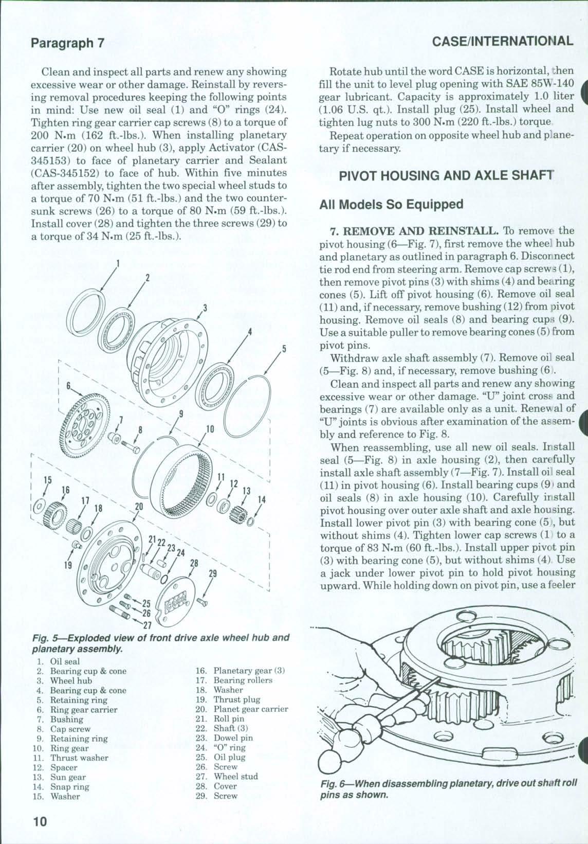
Fig. 5—Exploded view of front drive axle wheel hub
assembly.
gauge to measure distance between pivot housing and fiange ofpivot pin. Select a shim pack 0.1-0.2 mm (0.1)04-0.008 in.) less than the measurement. Divide the selected shim pack equally and install half on top pivot pin and half on bottom pivot pin. Shims are available in thicknesses of 0.10, 0.19 and 0.35 mm (0.004, 0.007 and 0.014 in.) Tighten top and bottom cap screws (1) to a torque of 137 N.m (100 ft.-lbs.)
The balance of reassembly is the reverse order of disassembly Lubricate pivot pin bearings with CASE 251 H EP or multipurpose Hthium grease Connect tie rod end to steering arm and tighten nut to a torque of230 N.m (170 ft.-lbs.)
DIFFERENTIAL AND BEVEL GEARS
All Models So Equipped
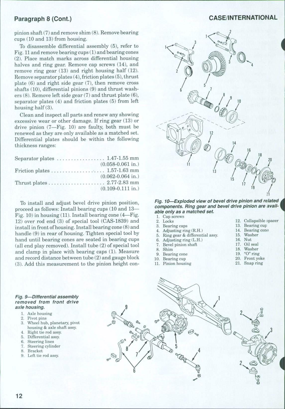
8. R&R AND OVERHAUL. To remove the differential assembly, first remove drain plug and drain oil from axle housing Remove front drive axle assembly as outlined in paragraph 5 and place assembly on axle stands Disconnect tie rods from steering arms Remove pivot pins (2—Fig. 9), then lift off wheel hub.
planetary, pivot housing and axle shaft assembly (3). Repeat operation on opposite side. Remove tie rods (4 and 9) from steering cylinder (7) Unbolt bracket (8), then unbolt and remove steering cylinder Remove retaining bolts and lift out pinion housing and differential assembly (5).
Refer to Fig. 10 and unbolt and remove locks (2). Loosen cap screws (1) and back off adjusting rings (4 and 6). Remove cap screws (1), bearing caps (3) and adjusting rings. Lift out ring gear and differential assembly (5) and lay aside for later disassembly.
Remove snap ring (21), front yoke (20), "O" ring (19), washer (18) and oil seal (17) Using special socket wrench (CAS-1885), remove nut (16) and tab washer (15) Use a soft hammer and drive pinion shaft (7)from housing (11) Remove bearing cone (14) and spacer (12), then press bearing cone (9) from
Fig. 7—Exploded view of pivot housing and components used on front drive axle.
Fig. 8—Exploded view of axle shaft assembly.
pinion shaft (7) and remove shim (8).Remove bearing cups (10 and 13) from housing.
To disassemble differential assembly (5), refer to Fig 11 and remove bearing cups (1) and bearing cones (2) Place match marks across differential housing halves and ring gear Remove cap screws (14), and remove ring gear (13) and right housing half (12) Remove separator plates (4),friction plates (5), thrust plate (6) and right side gear (7), then remove cross shafts (10), differential pinions (9) and thrust washers (8). Remove left side gear (7) and thrust plate (6), separator plates (4) and friction plates (5) from left housing half (3).
Clean and inspect all parts and renew any showing excessive wear or other damage If ring gear (13) or drive pinion (7—Fig 10) are faulty, both must be renewed as they are only available as a matched set. Differential plates should be within the following thickness ranges:
Separator plates
Friction plates
Thrust plates
1.47-1.55 mm
(0.058-0.061 in.)
1.57-1.63 mm (0.062-0.064 in.)
2.77-2.83 mm (0.109-0.111 in.)
To install and adjust bevel drive pinion position, proceed as follows: Install bearing cups (10 and 13 Fig. 10) in housing (11). Install bearing cone (4—Fig. 12) over rod end (3) of special tool (CAS-1839) and install in front ofhousing Install bearing cone(8) and handle (9) in rear of housing Tighten special tool by hand until bearing cones are seated in bearing cups (all end play removed) Install tube (2) of special tool and clamp in place with bearing caps (1). Measure and record distance between tube (2)and gauge block (3). Add this measurement to the pinion height con-
Fig. 10—Exploded view of bevel drive pinion and related components. Ring gear and bevel drive pinion are avail-
yoke
9—Differential assembly removed from front drive axle housing.
1. Axle housing
2 Pivot pins
3 Wheel hub, planetary, pivot housing &axle shaft assy
4 Right tie rod assy
5. Differential assy.
6 Steering lines
7 Steering cylinder
8 Bracket
9 Left tie rod assy
Fig.
stant, 109.75 mm (4.32 in.) Then, subtract the measurement etched on pinion shaft in millimeters from the previous sum to obtain the correct thickness of shims (8—Fig. 10)to be installed. Remove the special too] (CAS-1839) and bearing cones Shims are available in ten thicknesses from 2.5-3.4 mm (0.098 to 0.134 in.)
Install the previously determined shim pack (8) on pinion shaft (7). Heat bearing (9) to a temperature of 80-90° C (175-195° F) and install on pinion shaft. Insi:all collapsible spacer (12) on shaft, then install pimon shaft assembly in housing (11). Heat and install bearing cone (14)and install tab washer (15) and a nt^w nut (16). Tighten nut only until shaft end play is removed Use a cord wrapped around splined end ofpinion shaft and a spring scale to measure the force required to rotate the pinion shaft Bearing preload is correct when a spring scale reading of 92-137 N (20.7-30.8 lbs.) is obtained Tighten pinion shaft nut until desired spring scale reading (bearing preload) is obtained When preload is correct, use a hammer
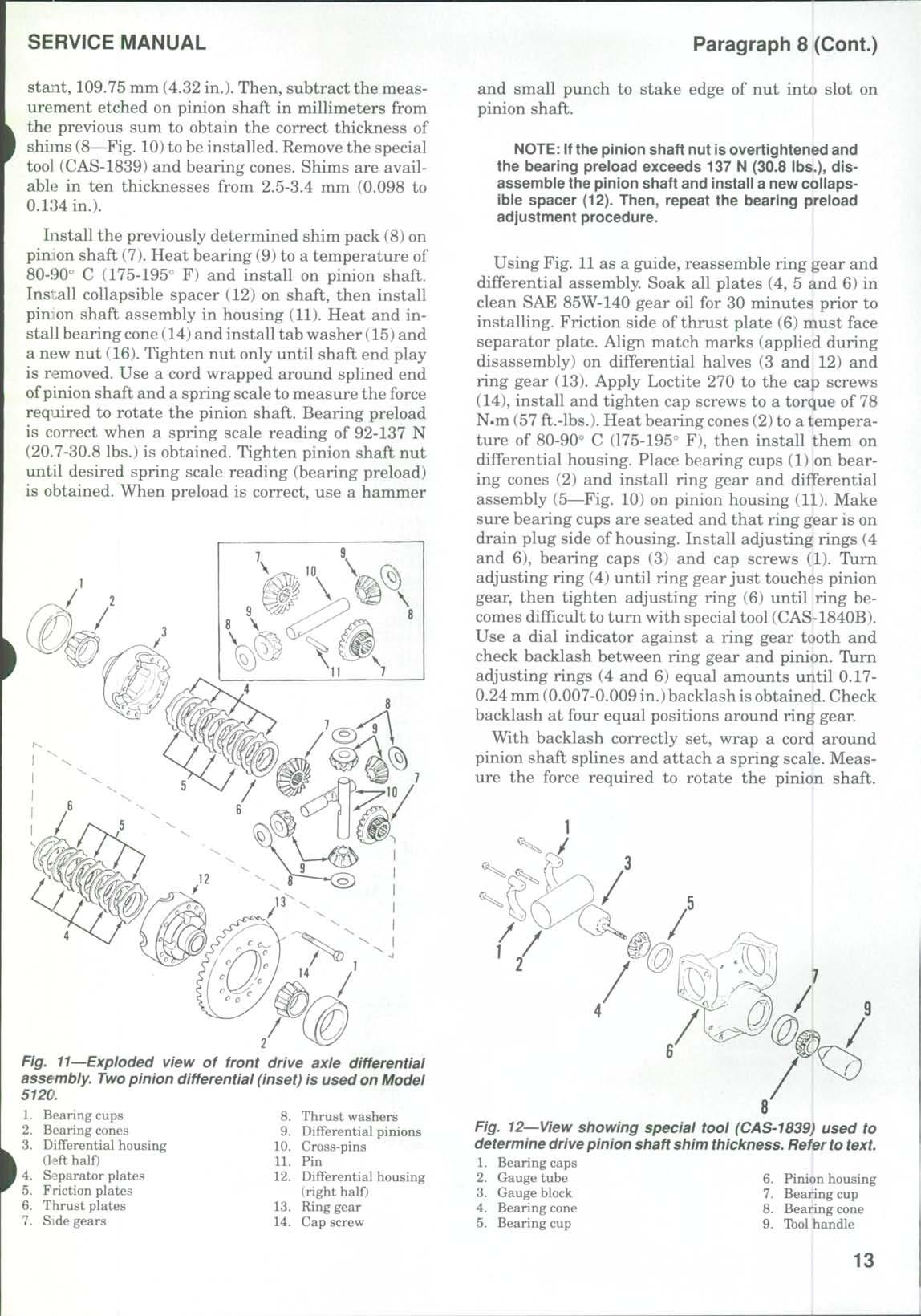
and small punch to stake edge of nut into slot on pinion shaft
NOTE: If the pinion shaft nut isovertightened and the bearing preload exceeds 137 N (30.8 lbs.), disassemble the pinion shaft and install a new collapsible spacer (12) Then, repeat the bearing preload adjustment procedure. |
Using Fig. 11as a guide, reassemble ring gear and differential assembly. Soak all plates (4, 5 and 6) in clean SAE 85W-140 gear oil for 30 minutes prior to installing Friction side of thrust plate (6) must face separator plate. Align match marks (applied during disassembly) on differential halves (3 and 12) and ring gear (13) Apply Loctite 270 to the cap screws (14), install and tighten cap screws to a torque of 78 N-m (57 ft.-lbs.) Heat bearing cones (2)to a temperature of 80-90° C (175-195° F), then install them on differential housing. Place bearing cups (1) on bearing cones (2) and install ring gear and differential assembly (5—Fig 10) on pinion housing (11) Make sure bearing cups are seated and that ring gear is on drain plug side of housing. Install adjusting rings (4 and 6), bearing caps (3) and cap screws (1). Turn adjusting ring (4) until ring gear just touches pinion gear, then tighten adjusting ring (6) until ring becomes difficult to turn with special tool (CAS-1840B). Use a dial indicator against a ring gear tooth and check backlash between ring gear and pinion. Turn adjusting rings (4 and 6) equal amounts until 0.170.24 mm (0.007-0.009 in.)backlash isobtained Check backlash at four equal positions around ring gear.
With backlash correctly set, wrap a cord around pinion shaft splines and attach a spring scale. Measure the force required to rotate the pinion shaft.
Fig. 11-^Exploded view of front drive axle differential assembly. Two pinion differential (inset) is used on Model 5120.
Spring scale reading (bearing preload) should be3146 N (7-10 lbs.) above the pinion bearing preload of 92-137 N (20.7-30.8 lbs.) previously set Tighten both adjusting rings an equal amount to get the recommended preload Recheck backlash and readjust if necessary Tighten cap screws (1) to 266 N»m (196 ft.-lbs) torque Install locks (2) and secure with cap screws tightened to 10 N*m (7 ft.-lbs.) torque
Install thrust washer (18) and new "O" ring (19) over end of pinion shaft. Apply Loctite 515 to metal cover of new oil seal (17) and install seal until seated in pinion housing. Install front yoke (20) and snap ring (21).
When reinstalling the bevel gears and differential assembly, apply Loctite 515 to pinion housing mounting face and tighten retaining bolts to a torque of 120 N»m (88 ft.-lbs.) on axles equipped with bolts and washers or 169 N.m (125 ft.-lbs.) on axles equipped with self-locking bolts
Install steering cylinder (7—Fig.9)and bracket (8). Tighten retaining cap screws to a torque of 90 N.m
Oil drain rubber protector (66 ft.-lbs.). Install tie rod assemblies (4 and 9) and tighten into cylinder rod to a torque of 300 N.m (221 ft.-lbs.). Install the wheel hub, planetary, pivot housing and axle shaft assemblies (3) by reversing the removal procedures Tighten pivot pin cap screws to a torque of 137 N.m (101 ft.-lbs.) Connect tie rod (nds to steering arms and tighten nuts to 230 N.m < 170 ft.-lbs.) torque Reinstall drive axle assembly as outlined in paragraph 5 Fill axle housing with SAE 85W-140 gear oil to level plug opening Capacity is approximately 6.0 liters (6.3 U.S qt.) Use new "O" rings and reconnect steering lines The balance of reassembly is the reverse of disassembly.
FRONT DRIVE SHAFT
All Models So Equipped
9. R&R AND OVERHAUL. Toremove front drive shaft, block rear wheels securely Refer to Fig 13 and unbolt and remove shield (5) with engine oil d'-ain plug rubber protector (6) Unbolt "U"joints from front and rear yokes and remove drive shaft assembly Unbolt "U"joints from drive shaft Place mark on^^ear yoke (2)and transmission housing for aid in reassembly Pull rear yokefrom transmission Remove oil seal (1) from rear yoke If necessary, remove snap ring (21—Fig 10) and remove front yoke (20) Clean and inspect all parts for excessive wear or other damage and renew as necessary Install new oil seal and reassemble drive shaft assembly Reinstall by reversing removal procedure Tighten bolts in "U" joints to a torque of 39-44 N.m (29-32 ft.-lbs.) Install shield with engine oil drain plug rubber protectc-r
TIE RODS AND TOE-IN
All Models So Equipped
10. ADJUSTMENT. To check and adjust the toein, refer to Fig. 14 and measure distance "A" and
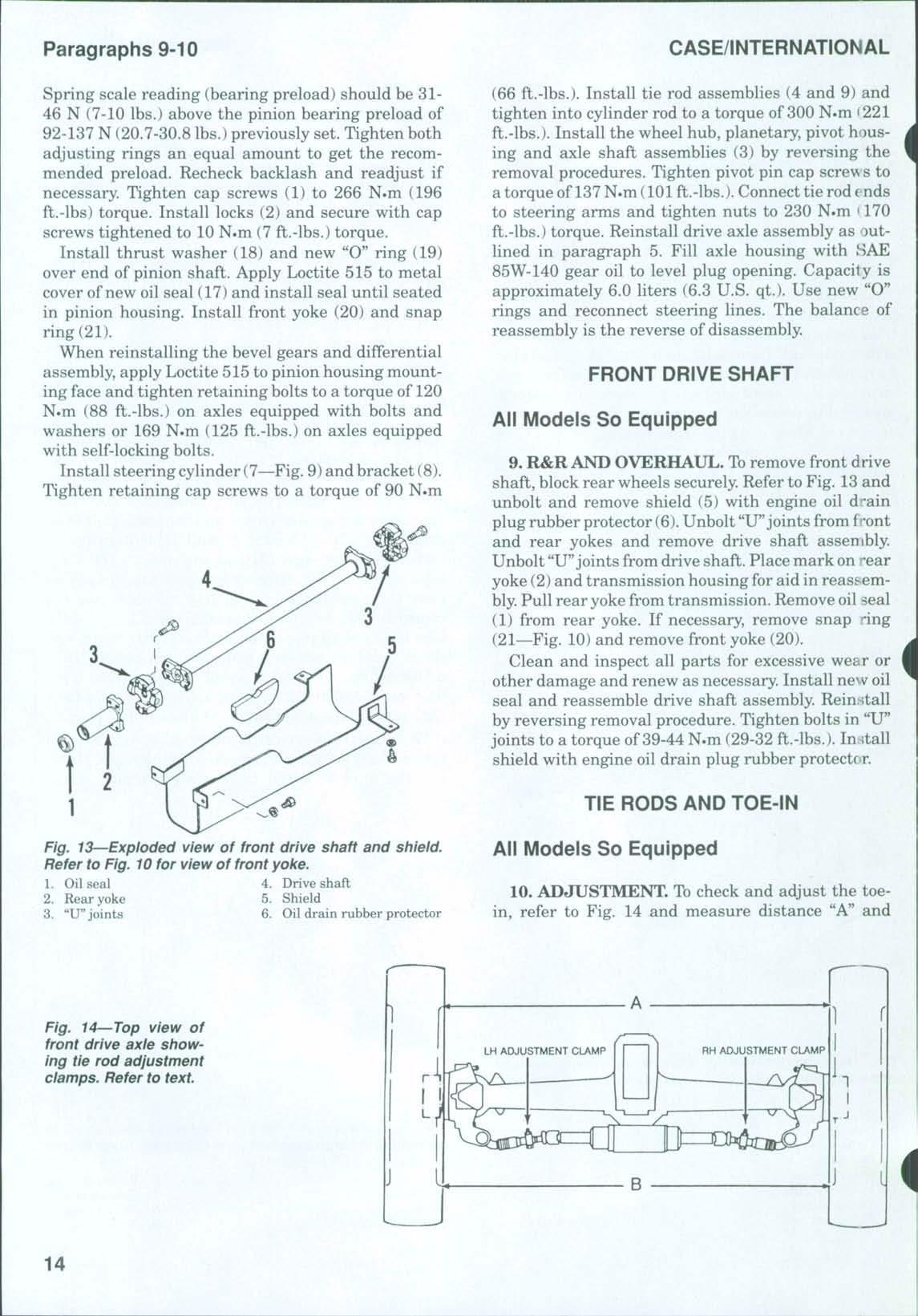
Fig. 14 Top view of front drive axle showing tie rod adjustment clamps. Refer to text.
Fig. 13 Exploded view of front drive shaft and shield. Refer to Fig. 10 for view of front yoke.

distance "B" from rim to rim at hub height. Distance "A" at front of wheel rim should be equal to or up to 5.0 mm (0.197 in.) less than distance "B" at rear of wheel rim.
If toe-in is incorrect, loosen adjustment clamps, then rotate steering cylinder piston rod as required to increase or decrease toe-in. Retighten tie rod clamps.
FRONT DRIVE AXLE CLUTCH
All Models So Equipped
1]. CLUTCH TORQUE TEST. Tocheck the front drive clutch slip torque, remove front drive shaft and shield as outlined in paragraph 9 Install special adapter (CAS-2131) to rear yoke (2—Fig 13) using "U" joint bolts. Tighten bolts to 29-32 ft.-lbs. (39-44 N.m). Have an assistant apply the service brakes and, using a torque multiplier (OEM-6107) and torque meter (OEM-6481), check torque required to turn the output shaft Torque should be as follows:
New clutch
2100 N.m (1550 ft.-lbs.)
Used clutch 1260-1540 N.m (930-1135 ft.-lbs.)
Clutch with worn plates 1000 N.m or less (738 ft.-lbs or less)
If clutch slips at a torque of 1000 N.m (738 ft.-lbs.) or less, remove and overhaul clutch as outlined in paragraph 12
12. R&R AND OVERHAUL. To remove the clutch, tractor must be split between the speed and range transmissions as follows: Block front wheels securely Install wood wedges between front axle housing and front support. Disconnect battery cables and drain transmission oil. Unbolt and remove seat assembly. Identify electrical connections and disconnect shuttle valve solenoids, pressure switches and ground leads Disconnect and cap hydraulic lines as required. Disconnect the inching clutch cable and the park brake cable. Unbolt and remove left step assembly. Drain fuel tank and disconnect breather hose, return hose and fuel supply hose Unbolt and remove fuel bank Remove the bottom three bolts from transmission Install transmission splitting rail (CAS10853) under range transmission and install a suitfLble safety stand under speed transmission. Remove the right rear wheel Install cab stands (CAS3389) under cab frame Disconnect pto cable, then I remove cable and switch from the bracket Unbolt ^and remove trailer electrical socket. Disconnect
•ground speed sensor connector and disconnect remote
I valv<3 control rods. Disconnect and cap brake hoses. Unbolt and remove the shield, then disconnect the
steering pressure switch connector, draft control solenoid connector and range switch connectors. Disconnect range selector rods and disconnect front-wheel drive solenoid connector. If so equipped, disconnect creeper transmission cable. Disconnect and cap hydraulic tubes from front-wheel drive valve and compensator valve. Raise the hood, remove exhaust extension and rear hood panel. Disconnect ground cables on both sides of cab. Remove rear cab mounting nuts and loosen front cab mounting bolts. Using the three cab support stands, raise cab. Remove speed to range transmission mounting bolts and carefully separate range transmission from speed transmission
Remove clutch assembly from front ofrange transmission as follows: Remove cap screws (22—Fig. 15) and front shield (23). Remove snap ring (1),shims (2)
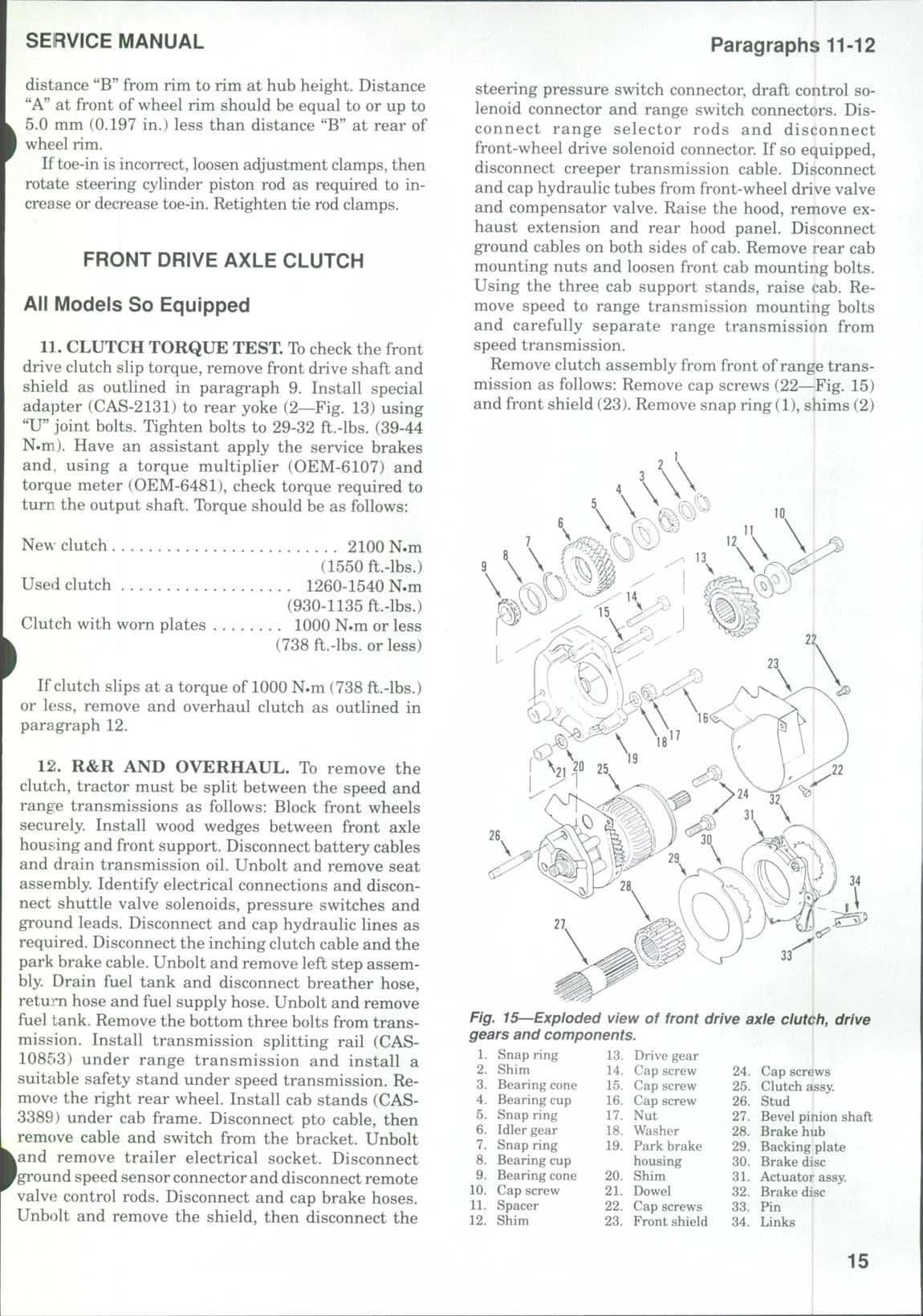
Snap ring
Idler gear
Snap ring
Bearing cup
Bearing cone
Cap screw
Spacer
Shim
Drive gear
Cap screw
Cap screw
Cap screw
Nut
Washer
Park brake housing
Shim
Dowel
Cap screws
Front shield 24 Cap screws
25. Clutch assy. 26 Stud 27 Bevel pinion shaft
28 Brake hub
29 Backing plate
30 Brake disc 31 Actuator assy 32. Brake disc 33 Pin 34. Links
Fig. 15 Exploded view of front drive axle clutch, drive gears and components.
Snap ring
Shim
Bearing cone
Bearing cup
and bearing cone (3). Turn cap screw (10), drive gear (13) and pinion shaft (27) until idler gear (6) can be removed. See Fig. 16.Gear teeth will align in only one position for gear removal. Remove idler gear (6—Fig. 15) and bearing cone (9). Remove bearing cups (4 and 8) and snap rings (5 and 7) from idler gear Remove cap screw (10), spacer (11), shims (12) and drive gear (13) Remove park brake pin (33) Remove park brake housing cap screws (15 and 16) and install two long alignment studs (CAS-1995), then remove cap screw (14) Remove nut (17), washer (18) and cap screws (24) Carefully slide the clutch assembly and park brake assembly forward until clutch assembly can be removed Do not lose shims (20) If dowel (21) holds brake housing to clutch assembly (25), use extreme care when removing the units as an assembly. Lay the assembly on a bench and separate. Remove park brake components (28 through 32).
To disassemble the front-wheel drive clutch, use a sharp knife to cut and remove seal ring (1—Fig 17) Remove snap ring (2), thrust washers (3 and 5) and thrust bearing (4). Remove snap ring (6) and shims (7), then using a suitable press, remove gear and clutch housing (19) from bearing housing (10). Remove bearing cone (8) Remove seal (17), spring (16), cap screws (15), shield (14) and cap screws (11) Remove bearing cups (9 and 12) from bearing housing (10).Using a suitable puller, removebearing cone(13) from gear assembly (19). Remove bearings (18 and 20) Remove thrust washer (21), thrust bearing (22) and recessed thrust washer (23) Using a press (Fig 17A), compress Belleville springs (39—Fig. 17). Remove snap ring (24) and thrust washer (25), then release press and remove shaft (40) and Belleville washers (39) Remove and discard "O" rings (36 and 38)from shaft (40) Remove snap ring (26),shims (27)
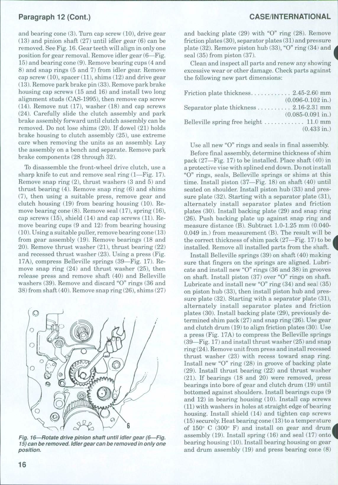
Fig. 16 Rotate drive pinion shaft until idler gear (6 Fig. 15) can be removed. Idlergear can be removed in only one position.
and backing plate (29) with "O" ring (28) Remove friction plates (30), separator plates (31)and pressure plate (32) Remove piston hub (33), "O" ring (341and seal (35) from piston (37)
Clean and inspect all parts and renew any showing excessive wear or other damage. Check parts against the following new part dimensions:
Friction plate thickness
Separator plate thickness
2.45-2.6(' mm (0.096-0.10:2 in.)
2.16-2.31 mm (0.085-0.09 Lin.)
Belleville spring free height ll.( mm (0.433 in.)
Use all new "O" rings and seals in final assembly. Before final assembly, determine thickness of shim pack (27—Fig 17) to be installed Place shaft (40) in a protective visewith splined end down. Donot ii stall "O" rings, seals, Belleville springs or shims at this time Install piston (37—Fig 18) on shaft (40) until seated on shoulder Install piston hub (33) and pressure plate (32) Starting with a separator plate (31), alternately install separator plates and friction plates (30). Install backing plate (29) and snap ring (26) Push backing plate up against snap ring and measure distance (B) Subtract 1.0-1.25 mm (0 0400.049 in.) from measurement (B) The result w.U be the correct thickness of shim pack (27—Fig. 17) to be i installed. Remove all installed parts from the shaft. Install Belleville springs (39) on shaft (40) making sure that fingers on the springs are aligned. Lubricate and install new "0" rings (36 and 38) in grooves on shaft Install piston (37) over "O" rings on shaft Lubricate and install new "O" ring (34) and sea (35) on piston hub (33), then install piston hub and pressure plate (32) Starting with a separator plate (31), alternately install separator plates and friction plates (30) Install backing plate (29), previously determined shim pack (27) and snap ring (26).Use gear and clutch drum (19) to align friction plates (30) Use a press (Fig 17A) to compress the Belleville spdngs (39—Fig 17)and install thrust washer (25) and snap ring (24) Removeunit from press and install recessed thrust washer (23) with recess toward snap ring. Install new "O" ring (28) in groove of backing plate (29) Install thrust bearing (22) and thrust washer (21) If bearings (18 and 20) were removed, press bearings into bore ofgear and clutch drum (19) until bottomed against shoulders. Install bearings cups (9 and 12) in bearing housing (10). Install cap screws (11)with washers in holes at straight edge of bearing housing Install shield (14) and tighten cap screws (15)securely. Heat bearing cone(13)to a temperature of 150° C (300° F) and install on gear and drumj assembly (19). Install spring (16) and seal (17) onto* bearing housing (10) Install bearing housing on gear and drum assembly (19) and press bearing core (8)