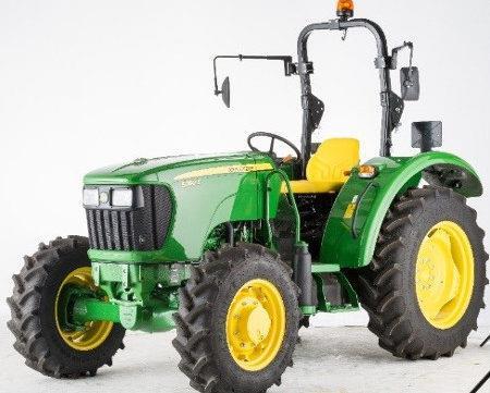
John Deere 5055E Workshop Service Manual

Page 1


John Deere Agriculture

5050E, 5055E, 5065E and 5075E Tractors

TECHNICAL MANUAL

5055E, 5065E, 5075E, 5050E

TM900319, July 2013

Table of contents

FOREWORD

Section 10 - GENERAL INFORMATION

Group 05 - Safety

Group 10 - General Specifications

Group 20 - Fuel and Lubricants

Group 25 - Serial Number Locations

Group 30 - Features and Accessories

Section 20 - ENGINE REPAIR

Group 05 - Engine

Group 10 - Cylinder Head and Valves

Group 15 - Cylinder Block, Liners, Pistons and Rods

Group 20 - Crankshaft, Main Bearings and Flywheel

Group 25 - Camshaft and Timing Gear Train

Group 30 - Lubrication System

Group 35 - Cooling System

Section 30 - FUEL AND AIR INTAKE SYSTEM REPAIR

Group 05 - Fuel System

Group 10 - Air Intake and Exhaust System

Group 15 - Speed Control Linkage

Section 40 - ELECTRICAL REPAIR

Group 05 - Battery, Starter and Alternator

Group 10 - Electrical System Components

Group 15 - Wiring Harness

Section 50 - POWER TRAIN REPAIR

Group 05 - Clutch Housing

Group 10 - Clutch Assembly

Group 15 - Transmission

Group 20 - Rear PTO Drive Shaft

Group 25 - Differential

Group 30 - Final Drives

Group 35 - Mechanical Front Wheel Drive – If Equipped

Section 60 - STEERING AND BRAKE REPAIR

Group 05 - Steering Repair

Group 10 - Brake Repair

Section 70 - HYDRAULIC REPAIR

Group 05 - Hydraulic Pump and Filter

Group 10 - JD Rockshaft

Group 15 - Selective Control Valve (SCV)

Section 80 - MISCELLANEOUS REPAIR

Group 05 - Front Axle

Group 10 - Wheels

Group 15 - 3-Point Hitch

Group 20 - Hood

Group 25 - Ballast

Section 90 - OPERATOR STATION REPAIR

Group 05 - Seat and Support

Group 06 - Right Console

Group 10 - Roll-GardRoll-Gard is a trademark of Deere & Company.

Group 15 - Center Console

Group 20 - Operator Station

Group 25 - Fenders

Section 210 - OPERATIONAL CHECKOUT PROCEDURES

Group 10 - Operational Checkout Procedures

Section 220 - ENGINE OPERATION, TESTS AND ADJUSTMENTS

Group 05 - Component Location

Group 10 - Theory of Operation

Group 15 - Diagnosis, Tests and Adjustments

Section 230 - FUEL/AIR OPERATION, TESTS AND ADJUSTMENTS

Group 05 - Component Location

Group 10 - Theory of Operation

Group 15 - Diagnosis, Tests and Adjustments

Section 240 - ELECTRICAL SYSTEM OPERATION, TESTS AND ADJUSTMENTS

Group 05 - Component Location

Group 10 - Theory of Operation

Group 15 - Diagnosis, Tests and Adjustments

Group 20 - Wiring Schematics

Group 25 - Component Information Connectors

Section 250 - POWER TRAIN OPERATION, TESTS AND ADJUSTMENTS

Group 05 - Component Location

Group 10 - Theory of Operation

Group 15 - Diagnosis, Tests and Adjustments

Section 260 - STEERING AND BRAKE OPERATION, TESTS & ADJUSTMENTS

Group 05 - Component Location

Group 10 - Theory of Operation

Group 15 - Diagnosis, Tests and Adjustments

Section 270 - HYDRAULIC SYSTEM OPERATION, TESTS AND ADJUSTMENTS

Group 05 - Component Location

Group 10 - Theory of Operation

Group 15 - Diagnosis

Group 20 - Hydraulic Tests With SCV

Group 25 - Hydraulic Tests With Mid-Mount Control Valve

Group 30 - Hydraulic Tests Whole System

Group 40 - Adjustments Hitch

Group 45 - Hydraulic Schematics

Foreword

This manual is written for an experienced technician. Essential tools required in performing certain service work are identified in this manual and are recommended for use.

Live with safety: Read the safety messages in the introduction of this manual and the cautions presented throughout the text of the manual.

CAUTION:

This is the safety-alert symbol. When you see this symbol on the machine or in this manual, be alert to the potential for personal injury.

Technical manuals are divided in two parts: repair and operation and tests. Repair sections tell how to repair the components. Operation and tests sections help you identify the majority of routine failures quickly.

Information is organized in groups for the various components requiring service instruction. At the beginning of each group are summary listings of all applicable essential tools, service equipment and tools, other materials needed to do the job, service parts kits, specifications, wear tolerances, and torque values.

Technical Manuals are concise guides for specific machines. They are on-the-job guides containing only the vital information needed for diagnosis, analysis, testing, and repair.

Fundamental service information is available from other sources covering basic theory of operation, fundamentals of troubleshooting, general maintenance, and basic type of failures and their causes.

Section 10 - GENERAL INFORMATION

Group 05 - Safety

Recognize Safety Information

Safety-alert symbol

This is a safety-alert symbol. When you see this symbol on your machine or in this manual, be alert to the potential for personal injury.

Follow recommended precautions and safe operating practices.

Understand Signal Words

Signal Words

A signal word DANGER, WARNING, or CAUTION is used with the safety-alert symbol. DANGER identifies the most serious hazards.

DANGER or WARNING safety signs are located near specific hazards. General precautions are listed on CAUTION safety signs. CAUTION also calls attention to safety messages in this manual.

Follow Safety Instructions

Safety Messages

Carefully read all safety messages in this manual and on your machine safety signs. Keep safety signs in good condition. Replace missing or damaged safety signs. Be sure new equipment components and repair parts include the current safety signs. Replacement safety signs are available from your John Deere dealer.

There can be additional safety information contained on parts and components sourced from suppliers that is not reproduced in this operator′s manual.

Learn how to operate the machine and how to use controls properly. Do not let anyone operate without instruction.

Keep your machine in proper working condition. Unauthorized modifications to the machine may impair the function and/or safety and affect machine life.

If you do not understand any part of this manual and need assistance, contact your John Deere dealer.

Prepare for Emergencies

First Aid Kit

Be prepared if a fire starts.

Keep a first aid kit and fire extinguisher handy.

Keep emergency numbers for doctors, ambulance service, hospital, and fire department near your telephone.

Wear Protective Clothing

Protective Clothing

Wear close fitting clothing and safety equipment appropriate to the job.

Operating equipment safely requires the full attention of the operator. Do not wear radio or music headphones while operating machine.

Protect Against Noise

Noise Exposure

Prolonged exposure to loud noise can cause impairment or loss of hearing.

Wear a suitable hearing protective device such as earmuffs or earplugs to protect against objectionable or uncomfortable loud noises.

Handle Fuel Safely—Avoid Fires

Avoid Fires

Handle fuel with care: it is highly flammable. Do not refuel the machine while smoking or when near open flame or sparks.

Always stop engine before refueling machine. Fill fuel tank outdoors.

Prevent fires by keeping machine clean of accumulated trash, grease, and debris. Always clean up spilled fuel.

Use only an approved fuel container for transporting flammable liquids.

Never fill fuel container in pickup truck with plastic bed liner. Always place fuel container on ground before refueling. Touch fuel container with fuel dispenser nozzle before removing can lid. Keep fuel dispenser nozzle in contact with fuel container inlet when filling.

Do not store fuel container where there is an open flame, spark, or pilot light such as within a water heater or other appliance.

Fire Prevention

To reduce the risk of fire, your tractor should be regularly inspected and cleaned.

Birds and other animals may build nests or bring other flammable materials into the engine compartment or onto the exhaust system. The tractor should be inspected and cleaned prior to the first use each day.

A build up of grass, crop material and other debris may occur during normal operation. This is especially true when operating in very dry conditions or conditions where airborne crop material or crop dust is present. Any such build up must be removed to ensure proper machine function and to reduce the risk of fire. The tractor must be inspected and cleaned periodically throughout the day.

Regular and thorough cleaning of the tractor combined with other routine maintenance procedures listed in the Operator’s Manual greatly reduce the risk of fire and the chance of costly downtime.

Do not store fuel container where there is an open flame, spark, or pilot light such as within a water heater or other appliance.

Check fuel lines, tank, cap, and fittings frequently for damage, cracks or leaks. Replace if necessary.

Follow all operational and safety procedures posted on the machine and the Operator’s Manual. Be careful of hot engine and exhaust components during inspection and cleaning. Before carrying out any inspection or cleaning, always shut OFF the engine, place the transmission in PARK or set parking brake, and remove the key. Removal of the key will prevent others from starting the tractor during inspection and cleaning.

Use Foldable ROPS and Seat Belt Properly

Fasten Your Seat Belt

If this tractor is equipped with a foldable ROPS, keep the ROPS in the fully extended and locked position. If the tractor is ever operated with ROPS folded (e.g., to enter a low building), drive with extreme caution. Do NOT use seat belt with the ROPS folded.

Return the ROPS to the raised, fully extended and locked position as soon as the tractor is operated under normal conditions. Always fasten your seat belt when the ROPS is fully extended and locked.

Stay Clear of Rotating Drivelines

Rotating Drivelines

Drivelines

Entanglement in rotating driveline can cause serious injury or death.

Keep tractor master shield and driveline shields in place at all times. Make sure rotating shields turn freely.

Wear close fitting clothing. Stop the engine and be sure that PTO driveline is stopped before making adjustments, connections, or cleaning out PTO driven equipment.

Do not install any adapter device between the tractor and the primary implement PTO drive shaft that will allow a 1000 rpm tractor shaft to power a 540 rpm implement at speeds higher than 540 rpm.

Do not install any adapter device that results in a portion of the rotating implement shaft, tractor shaft, or the adapter to be unguarded. The tractor master shield shall overlap the end of the splined shaft and the added adaptor device as outlined in the table.

Use Steps and Handholds Correctly

Use Handholds and Steps

Prevent falls by facing the machine when getting on and off. Maintain 3-point contact with steps, handholds, and handrails.

Use extra care when mud, snow, or moisture present slippery conditions. Keep steps clean and free of grease or oil. Never jump when exiting machine. Never mount or dismount a moving machine.

Read Operator Manuals for ISOBUS Implements

In addition to GreenStar Applications, this display can be used as a display device for any implement that meets ISO 11783 standard. This includes capability to control ISOBUS implements. When used in this manner, information and implement control functions placed on the display are provided by the implement and are the responsibility of the implement manufacturer. Some of these implement functions could provide a hazard either to the Operator or a bystander. Read the operator manual provided by the implement manufacturer and observe all safety messages in manual and on implement prior to use.

Turn static files into dynamic content formats.

Create a flipbook
Issuu converts static files into: digital portfolios, online yearbooks, online catalogs, digital photo albums and more. Sign up and create your flipbook.
John Deere 5055E Workshop Service Manual by The Service Repair Manual - Issuu