ABBREVIATIONS USED IN THIS MANUAL (TERMS)
AIRFLOW METER (2RZ-FE, 3RZ-FE)
ALTERNATOR

ABBREVIATIONS USED IN THIS MANUAL (TERMS)
AIRFLOW METER (2RZ-FE, 3RZ-FE)
ALTERNATOR
ALPHABETICAL INDEX (A - L)
ENGINE SERIAL NUMBER (IDENTIFICATION INFORMATION)
EVAPORATIVE EMISSION (EVAP) CONTROL SYSTEM
EXHAUST GAS RECIRCULATION (EGR) SYSTEM (2RZ-FE)
CAMSHAFT POSITION SENSOR (2RZ -FE, 3RZ -FE)
CHARGING (PREPARATION)
CHARGING (SERVICE SPECIFICATIONS)
CHARGING SYSTEM
CIRCUIT INSPECTION (ENGINE (1RZ -E)) (DIAGNOSTICS)
CIRCUIT INSPECTION (ENGINE (2RZ-FE, 3RZ-FE)) (DIAGNOSTICS)
CIRCUIT OPENING RELAY
CO (1RZ, 3RZ-F)
CO (1RZ-E, 3RZ-FE)
CO/HC (2RZ-FE)
COMPRESSION (2RZ -FE)
COOLANT
COOLING (PREPARATION)
COOLING (SERVICE SPECIFICATIONS)
CRANKSHAFT POSITION SENSOR (2RZ-FE, 3RZ-FE)
CUSTOMER PROBLEM ANALYSIS CHECK (ENGINE (1RZ -E))
(DIAGNOSTICS)
CUSTOMER PROBLEM ANALYSIS CHECK (ENGINE (2RZ -FE, 3RZ -FE)) (DIAGNOSTICS)
CYLINDERBLOCK (2RZ-FE, 3RZ-F)
CYLINDER HEAD (1RZ-E)
CYLINDER HEAD (2RZ-FE)
CYLINDER HEAD (3RZ-FE)
DIAGNOSTICTROUBLE CODE CHART (ENGINE (1RZ -E)) (DIAGNOSTICS)
DIAGNOSTICTROUBLE CODE CHART (ENGINE (2RZ -FE, 3RZ -FE)) (DIAGNOSTICS)
EFI MAIN RELAY
EFI SYSTEM
ELECTRONIC FUEL INJECTION
(PREPARATION)
ELECTRONIC FUEL INJECTION
(SERVICE SPECIFICATIONS)
EMISSION CONTROL (PREPARATION)
EMISSION CONTROL (SERVICE SPECIFICATIONS)
EMISSION CONTROL SYSTEM
ENGINE (1RZ -E) (DIAGNOSTICS)
ENGINE (2RZ -FE, 3RZ -FE) (DIAGNOSTICS)
ENGINE CONTROL UNIT (ECU)
ENGINE MECHANICAL (PREPARATION)
ENGINE MECHANICAL (SERVICE SPECIFICATIONS)
FUEL CUT RPM
FUEL PRESSURE PULSATION DAMPER (2RZ -FE, 3RZ -FE)
FUEL PRESSURE REGULATOR (2RZ -FE)
FUEL PUMP
GENERAL INFORMATION (HOW TO TROUBLESHOOT ECU CONTROLLED SYSTEMS)
GENERAL INFORMATION
-3
-5 (HOW TO USE THIS MANUAL)
GENERAL INFORMATION
-7 (REPAIRINSTRUCTIONS)
HOW TOPROCEED WITH TROUBLESHOOTING (ENGINE (1RZ-E)) (DIAGNOSTICS)
HOW TOPROCEED WITH TROUBLESHOOTING (ENGINE (2RZ -FE, 3RZ -FE)) (DIAGNOSTICS)
HOW TOPROCEED WITH TROUBLESHOOTING (HOW TO TROUBLESHOOT ECU CONTROLLEDSYSTEMS)
HOW TO TROUBLESHOOT ECU CONTROLLED SYSTEMS
60
-15
-1
HOW TO USE THE DIAGNOSTICCHART AND INSPECTION PROCEDURE (HOW TO TROUBLESHOOT ECU CONTROLLEDSYSTEMS)
HOW TO USE THIS MANUAL
IDENTIFICATIONINFORMATION
IDLESPEED (1RZ-E)
IDLE SPEED (2RZ-FE, 3RZ-FE)
IDLE SPEED CONTROL (ISC) VALVE (2RZ -FE)
IGNITION (PREPARATION)
IGNITION (SERVICE SPECIFICATIONS)
IGNITION COIL (2RZ-FE, 3RZ-FE)
IGNITIONSYSTEM (2RZ-FE, 3RZ-FE)
TIMING (1RZ -E)
IGNITION TIMING (2RZ-FE, 3RZ-FE)
INJECTOR (2RZ-FE, 3RZ-FE)
KNOCKSENSOR (2RZ-FE, 3RZ-FE)
LUBRICATION (PREPARATION)
LUBRICATION (SERVICE SPECIFICATIONS)
OIL PUMP
OXYGENSENSOR (2RZ-FE)
PARTS LAYOUTAND SCHEMATIC DRAWING
PARTS LOCATION (ENGINE (1RZ -E)) (DIAGNOSTICS)
PARTS LOCATION (ENGINE (2RZ -FE, 3RZ -FE)) (DIAGNOSTICS)
POSITIVE CRANKCASE VENTILATION (PCV)SYSTEM
PRE -CHECK (ENGINE (1RZ -E)) (DIAGNOSTICS)
PRE -CHECK (ENGINE (2RZ -FE, 3RZ -FE)) (DIAGNOSTICS)
PRECAUTION (FOR ALL OF VEHICLES)
PROBLEM SYMPTOMS TABLE (ENGINE (1RZ -E)) (DIAGNOSTICS)
PROBLEMSYMPTOMS TABLE (ENGINE (2RZ -FE, 3RZ -FE)) (DIAGNOSTICS)
BOLT (SERVICE SPECIFICATIONS)
(PREPARATION)
(SERVICE SPECIFICATIONS)
TERMINALS OF ECU (ENGINE (1RZ -E)) (DIAGNOSTICS)
TERMINALS OF ECU (ENGINE (2RZ -FE, 3RZ -FE)) (DIAGNOSTICS)
TERMS
THERMOSTAT
THREE -WAY CATALYTIC CONVERTER
-26
-7 (TWC) SYSTEM (2RZ -FE)
THROTTLE BODY (1RZ-E)
THROTTLE BODY (2RZ -FE, 3RZ -FE)
TIMING CHAIN (1RZ, 1RZ-E)
TIMING CHAIN (2RZ-FE)
TIMING CHAIN (3RZ-F, 3RZ-FE)
VALVE CLEARANCE (2RZ-FE)
VARIABLE RESISTOR
VSV FOR EVAPORATIVE EMISSION (EVAP) (2RZ-FE, 3RZ-FE)
VSV FOR EXHAUST GAS RECIRCULATION (EGR) (2RZ-FE)
-10
-8
-56
-53
This SUPPLEMENT has been prepared to provide information covering general service repairs for the 1RZ,1RZ - E, 2RZ-FE, 3RZ - F and 3RZ - FE ENGINES equipped on the TOYOTA HILUX.
Applicable models: RZN142, 144, 147, 148, 149, 154, 168, 169, 173, 174, 193 series
Fortheservicespecificationsandrepairproceduresof theabovemodelotherthanthose listedin thissupplement, refer to the following manuals.
S 1RZ, 2RZ, 2RZ-E Engine Repair Manual
S 2RZ, 2RZ-E Engine Repair Manual Supplement N/A FOR THE HILUX
S 3RZ-F, 3RZ-FE Engine Repair Manual
S 1RZ-E Engine Repair Manual
S 1RZ, 2RZ-E Repair Manual For Emission Control N/A FOR THE HILUX
S 3RZ-F Repair Manual For Emission Control N/A FOR THE HILUX
All information in this manual is based on the latest product information at the time of publication. However, specifications and procedures are subject to change without notice.
1997TOYOTA MOTORCORPORATION
All rights reserved. This CD may not be reproduced or copied, in whole or in part, without the writtenpermission of Toyota Motor Corporation.
First Printing: Aug. 18. 1997 01-970818-00
This manual does not include all the necessary items about repair and service. This manual is made for the purpose of the use for the persons who have special techniques and certifications. In the cases that non -specialized or uncertified technicians perform repair or service only using this manual or without proper equipment or tool, that may cause severe injury to you or other people around and also cause damage to your customer’s vehicle.
In order to prevent dangerous operation and damages to your customer’s vehicle, be sure to follow the instruction shown below.
S Must read this manual thoroughly. It is especially important to have good understanding all the contents written in the PRECAUTION of ”IN” section.
S The service method written in this manual is very effective to perform repair and service. When performing the operations following the procedures using this manual, be sure to use tools specified and recommended. If using non -specified or recommended tools and service method, be sure to confirm safety of the technicians and any possibility of causing personal injury or damage to the customer’s vehicle before starting the operation.
S If part replacement is necessary, must replace the part with the same part number or equivalent part. Do not replace it with inferior quality.
S It is important to note that this manual contains various ”Cautions” and ”Notices” that must be carefully observed in order to reduce the risk of personal injury during service or repair, or the possibility that improper service or repair may damage the vehicle or render it unsafe. It is also important to understand that these ”Cautions” and ”Notices” are not exhaustive, because it is important to warn of all the possible hazardous consequences that might result from failure to follow these instructions.
MAIN INDEX: HILUX
SUPPLEMENT: ENGINE 3RZ-F & 3RZ-FE
August 1997
INTRODUCTION PREPARATION
SERVICE SPECIFICATIONS
DIAGNOSTICS
ENGINE MECHANICAL
EMISSION CONTROL
ELECTRONIC FUEL INJECTION
COOLING
LUBRICATION
IGNITION
STARTING CHARGING
ALPHABETICAL INDEX


HOW TO USE THIS MANUAL IN -1
GENERAL INFORMATION
IDENTIFICATION INFORMATION .......... IN
ENGINE SERIAL NUMBER IN-3
REPAIR INSTRUCTIONS IN -4
GENERAL INFORMATION FOR ALL OF VEHICLES
PRECAUTION HOW TO TROUBLESHOOT IN
ECU CONTROLLED SYSTEMS IN -8
GENERAL INFORMATION
HOW TO PROCEED WITH TROUBLESHOOTING
HOW TO USE THE DIAGNOSTIC CHART AND INSPECTION PROCEDURE IN
TERMS IN -26
ABBREVIATIONS USED IN THIS MANUAL IN-26
1.□□ I□ NDE□ X
An INDEX is provided on the first page of each section to guide you to the item to be repaired. To assist you in finding your way through the manual, the Section Title and major heading are given at the top of every page.
2. □□ G□ E□ NE□ RAL□DE□ S□ CRI□ P□ TI□□ O□ N
At the beginning of each section, a General Description is given that pertains to all repair operations contained in that section.
Read these precautions before starting any repair task.
3. □ TROUBLESHOOTING TROUBLESHOOTING tables are included for each system to help you diagnose the problem and find the cause. The fundamentals of how to proceed with troubleshooting are described on page IN -8
Be sure to read this before performing troubleshooting.
4. □ PREPARATION
Preparation lists the SST (Special Service Tools), recommended tools, equipment, lubricant and SSM (Special Service Materials) which should be prepared before beginning the operation and explains the purpose of each one.
5. □□ RE□ PAI□ R□ P□ RO□ CE□ DURE□ S
Most repair operations begin with an overview illustration. It identifies the components and shows how the parts fit together.
Example:
18(185, 13)
Throttle Body
Throttle Position Sensor Connector
Vacuum Hose
Gasket Water Bypass Hose

INTRODUCTION -- HOW TO USE THIS MANUAL
The procedures are presented in a step -by -step format:
S The illustration shows what to do and where to do it.
S The task heading tells what to do.
S The detailed text tells how to perform the task and gives other information such as specifications and warnings.
Example:

Illustration: what to do and where
Task heading : what to do

(a) PlaceSSTandadialindicatorontotheoverdrivebrake Piston as shown in the illustration.
SST 09350 -30020 (09350 -06120)

Set part No.

Component part No.
Detailed text : how to do task

(b) Measure the stroke applying and releasing the compressed air (392 785 kPa, 4 8 kgf/cm2 or 57 114psi) asshown in the illustration.
Piston stroke: 1.40 — 1.70 mm (0.0551 — 0.0669 in.)

Specification
This format provides the experienced technician with a FAST TRACK to the information needed. The upper case task heading can be read at a glance when necessary, and the text below it provides detailed information. Important specifications and warnings always stand out in bold type.
6. □□ RE□ FE□ RE□ NCE□ S
References have been kept to a minimum. However, when they are required you are given the page to refer to.
7. □ SPECIFICATIONS
Specifications are presented in bold type throughout the text where needed. You never have to leave the procedure to look up your specifications. They are also found in Service Specifications section, for quick reference.
8. □□ CAUTI□ O□ NS,□□NO□ TI□ CE□ S,□□HI□ NTS:□
S CAUTIONS are presented in bold type, and indicate there is a possibility of injury to you or other people.
S NOTICES are also presented in bold type, and indicate the possibility of damage to the components being repaired.
S HINTS are separated from the text but do not appear in bold. They provide additional information to help you perform the repair efficiently.
9. □□ SI□□UNI□ T
The UNITS given in this manual are primarily expressed according to the SI UNIT (International System of Unit), and alternately expressed in the metric system and in the English System.
Example:
Torque:30 N∙m (310 kgf∙cm,22 ft∙lbf)

INTRODUCTION -- IDENTIFICATION INFORMATION
The engine serial number is stamped on the engine block as shown.

INTRODUCTION -- REPAIR INSTRUCTIONS
(a) Use fender, seat and floor covers to keep the vehicle clean and prevent damage.
(b) During disassembly, keep parts in the appropriate order to facilitate reassembly.
(c) Observe the following:
(1) Before performing electrical work, disconnect the negative ( -) terminal cable from the battery.
(2) If it is necessary to disconnect the battery for inspection or repair, always disconnect the negative ( -) terminal cable which is grounded to the vehicle body.
(3) To prevent damage to the battery terminal, loosen the cable nut and raise the cable straight up without twisting or prying it.
(4) Clean the battery terminals and cable ends with a clean shop rag. Do not scrape them with a file or other abrasive objects.
(5) Install the cable ends to the battery terminals with the nut loose, and tighten the nut after installation. Do not use a hammer to tap the cable ends onto the terminals.
(6) Be sure the cover for the positive (+) terminal is properly in place.
(d) Check hose and wiring connectors to make sure that they are secure and correct.
(e) Non -reusable parts
(1) Always replace cotter pins, gaskets, O -rings and oil seals etc. with new ones.
(2) Non -reusable parts are indicated in the component illustrations by the ” z ” symbol.
(f) Precoated parts
Precoated parts are bolts and nuts, etc. that are coated with a seal lock adhesive at the factory.
(1) If a precoated part is retightened, loosened or caused to move in any way, it must be recoated with the specified adhesive.
(2) When reusing precoated parts, clean off the old adhesive and dry with compressed air. Then apply the specified seal lock adhesive to the bolt, nut or threads.
(3) Precoated parts are indicated in the component illustrations by the ” L ” symbol.
(g) When necessary, use a sealer on gaskets to prevent leaks.
INTRODUCTION -- REPAIR INSTRUCTIONS
(h) Carefully observe all specifications for bolt tightening torques. Always use a torque wrench.
(i) Use of special service tools (SST) and special service materials (SSM) may be required, depending on the nature of the repair. Be sure to use SST and SSM where specified and follow the proper work procedure. A list of SST and SSM can be found in the preparation part at the front of each section in this manual.
Medium Current Fuseand HighCurrentFuse Equal Amperage Rating

Illustration
(j) When replacing fuses, be sure the new fuse has the correct amperage rating. DO NOT exceed the rating or use one with a lower rating.

MEDIUM CURRENTFUSE M FUSE HIGH CURRENT FUSE H FUSE FUSIBLE LINK FL
CIRCUIT BREAKER CB
(k) Care must be taken when jacking up and supporting the vehicle. Be sure to lift and support the vehicle at the proper locations.
(1) If the vehicle is to be jacked up only at the front or rear end, be sure to block the wheels at the opposite end in order to ensure safety.
(2) After the vehicle is jacked up, be sure to support it on stands. It is extremely dangerous to do any work on a vehicle raised on a jack alone, even for a small job that can be finished quickly.
INTRODUCTION -- REPAIR INSTRUCTIONS
(l) Observe the following precautions to avoid damage to the following parts:
(1) Do not open the cover or case of the ECU unless absolutely necessary. (If the IC terminals are touched, the IC may be destroyed by static electricity.)


(2) To disconnect vacuum hoses, pull on the end, not the middle of the hose.
(3) To pull apart electrical connectors, pull on the connector itself, not the wires.
(4) Be careful not to drop electrical components, such as sensors or relays. If they are dropped on a hard floor, they should be replaced and not reused.
(5) When steam cleaning an engine, protect the electronic components, air filter and emissions -related components from water.
(6) Never use an impact wrench to remove or install temperature switches or temperature sensors.
(7) When checking continuity at the wire connector, insert the tester probe carefully to prevent terminals from bending.
(8) When using a vacuum gauge, never force the hose onto a connector that is too large. Use a step -down adapter instead. Once the hose has been stretched, it may leak.
(m) Tag hoses before disconnecting them:
(1) When disconnecting vacuum hoses, use tags to identify how they should be reconnected.
(2) After completing a job, double check that the vacuum hoses are properly connected. A label under the hood shows the proper layout.
(n) Unless otherwise stated, all resistance is measured at an ambient temperature of 20˚C (68˚F). Because the resistance may be outside specifications if measured at high temperatures immediately after the vehicle has been running, measurements should be made when the engine has cooled down.
INTRODUCTION -- FOR ALL OF VEHICLES
1.□ FOR□VEHICLES□EQUIPPED□WITH□ A□CATALYTIC□CONVERTER
CAUTION:
If large amounts of unburned gasoline flow into the converter, it may overheat and create a fire hazard. To prevent this, observe the following precautions and explain them to your customer.
(a) Use only unleaded gasoline
(b) Avoid prolonged idling
Avoid running the engine at idle speed for more than 20 minutes.
(c) Avoid spark jump test
(1) Performspark jump test only when absolutely necessary. Perform this test asrapidly aspossible.
(2) While testing, never race the engine.
(d) Avoid prolonged engine compression measurement
Engine compression tests must be done as rapidly as possible.
(e) Do not run engine when fuel tank is nearly empty
This may cause the engine to misfire and create an extra load on the converter.
(f) Avoid coasting with ignition turned off and prolonged braking
(g) Do not dispose of used catalyst along with parts contaminated with gasoline or oil
2.□ IF□VEHICLE□IS□EQUIPPED□WITH□MOBILE□COMMUNICATION□SYSTEM
For vehicles with mobile communication systems such as two -way radios and cellular telephones, observe the following precautions.
(1) Install the antenna as far as possible away from the ECU and sensors of the vehicle’s electronic system.
(2) Install the antenna feeder at least 20 cm (7.87 in.) away from the ECU and sensors of the vehicle’s electronics systems. For details about ECU and sensors locations, refer to the section on the applicable component.
(3) Do not wind the antenna feeder together with the other wiring. As much as possible, also avoid running the antenna feeder parallel with other wire harnesses.
(4) Confirm that the antenna and feeder are correctly adjusted.
(5) Do not install powerful mobile communications system.
3.□□ FO□ R□USI□□NG□HAND□□ HE□ LD□TE□ S□ T□ E□ R CAUTION:
Observe the following for safety reasons:
S Before using the hand-held tester, the hand-held tester’s operator manual should be read throughly.
S Be sure to route all cables securely when driving with the hand-held tester connected to the vehicle. (i.e. Keep cables away from feet, pedals, steering wheel and shift lever.)
S Twopersons arerequired whentest driving withthehand-heldtester, onepersonto drivethe vehicle and one person to operate the hand -held tester.
INTRODUCTION -- HOW TO TROUBLESHOOT ECU CONTROLLED SYSTEMS
A large number of ECU controlled systems are used in the HILUX. In general, the ECU controlled system is considered to be a very intricate system requiring a high level of technical knowledge and expert skill to troubleshoot. However, the fact is that if you proceed to inspect the circuits one by one, troubleshooting of these systems is not complex. If you have adequate understanding of the system and a basic knowledge of electricity, accurate diagnosis and necessary repair can be performed to locate and fix the problem. This manual is designed through emphasis of the above standpoint to help service technicians perform accurate and effective troubleshooting, and is compiled for the following major ECU controlled systems: System
The troubleshooting procedure and how to make use of it are described on the following pages.
HOW TO PROCEED WITH TROUBLESHOOTING IN-9
1. CUSTOMER PROBLEM ANALYSIS IN-10
2. SYMPTOM CONFIRMATION AND DIAGNOSTIC TROUBLE CODE CHECK IN-11/12
3. SYMPTOM SIMULATION IN-13/14
4. 1RZ-E: DIAGNOSTIC TROUBLE CODE CHART IN-15
5. 2RZ-FE, 3RZ-FE: DIAGNOSTIC TROUBLE CODE CHART IN-16
6. PROBLEM SYMPTOMS TABLE IN-17
7. 1RZ-FE: CIRCUIT INSPECTION IN-18
8. 2RZ-FE, 3RZ-FE: CIRCUIT INSPECTION IN-19/20
Carry out troubleshooting in accordance with the procedure on the following page. Here, only the basic procedure is shown. Details are provided in each section, showing the most effective methods for each circuit. Confirm the troubleshooting procedures first for the relevant circuit before beginning troubleshooting of that circuit.
Vehicle Brought Workshop
Customer Problem Analysis
Ask the customer about the conditions and the environment when the problem occurred.
Confirm the symptoms and the problem conditions, and check the diagnostic trouble codes. (When the problem symptoms do not appear during confirmation, use the symptom simulation method described later on.)

Check the results obtain in Step 2, then confirm the inspection procedure for the system or the part which should be checked using the diagnostic trouble code chart or the matrix chart of problem symptoms.
Check and repair the affected system or part in accordance with the instructions in Step 6.
After completing repairs, confirm that the problem has been eliminated. (If the problem is not reproduced, perform the confirmation test under the same conditions and in the same environment as when it occurred for the first time.)
In troubleshooting, the problem symptoms must be confirmed accurately and all preconceptions must be cleared away in order to give an accurate judgment. To ascertain just what the problem symptoms are, it is extremely important to ask the customer about the problem and the conditions at the time it occurred. Important Point in the Problem Analysis:
The following 5 items are important points in the problem analysis. Past problems which are thought to be unrelated and the repair history, etc. may also help in some cases, so as much information as possible should be gathered and its relationship with the problem symptoms should be correctly ascertained for reference in troubleshooting. A customer problem analysis table is provided in the troubleshooting section for each system for your use.
Important Points in the Customer Problem Analysis
D What Vehicle model, system name
D When Date, time, occurrence frequency

D Where Road conditions
D Under what conditions? Running conditions, driving conditions, weather conditions
D How did it happen? Problem symptoms
(Sample) Engine control system check sheet.
Customer’s
Driver’s
The diagnostic system in the HILUX fulfills various functions. The first function is the Diagnostic Trouble Code Check in which a malfunction in the signal circuits to the ECU is stored in code in the ECU memory at the time of occurrence, to be output by the technician during troubleshooting. Another function is the Input Signal Check which checks if the signals from various switches are sent to the ECU correctly. By using these check functions, the problem areas can be narrowed down quickly and troubleshooting can be performed effectively. Diagnostic functions are incorporated in the following systems in the HILUX.
Trouble Input Signal Check Other Diagnosis Code Check (Sensor Check) Function
f Diagnostic Test (with Check Mode) Mode
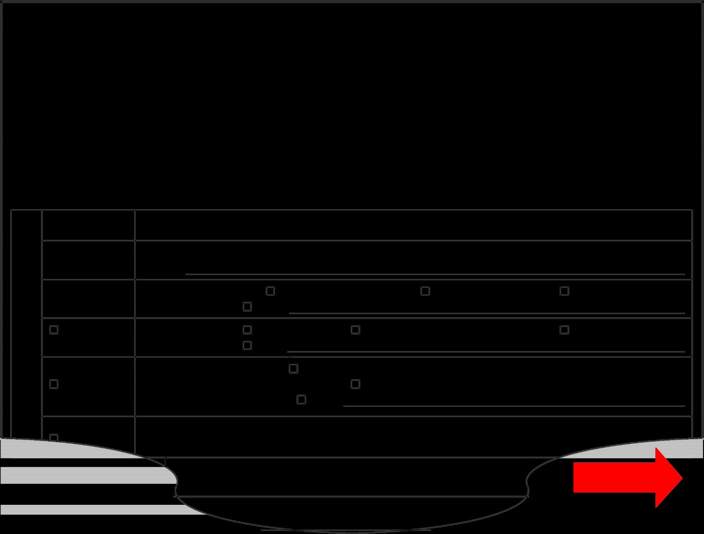
In diagnostic trouble code check, it is very important to determine whether the problem indicated by the diagnostic trouble code is still occurring or occurred in the past but returned to normal at present. In addition, it must be checked in the problem symptom check whether the malfunction indicated by the diagnostic trouble code is directly related to the problem symptom or not. For this reason, the diagnostic trouble codes should be checked before and after the symptom confirmation to determine the current conditions, as shown in the table below. If this is not done, it may, depending on the case, result in unnecessary troubleshooting for normally operating systems, thus making it more difficult to locate the problem, or in repairs not pertinent to the problem. Therefore, always follow the procedure in correct order and perform the diagnostic trouble code check.
Diagnostic Trouble Code Check (Make a note of and then clear)
Diagnostic Trouble Code Display
Normal Code Display
Confirmation of Symptoms
Problem symptoms exist
Diagnostic Trouble Code Check
Same diagnostic trouble code is displayed
Normal code is displayed
No problem symptoms exist
Problem symptoms exist
No problem symptoms exist
Normal code is displayed
Normal code is displayed
Problem Condition
Problem is still occurring in the diagnostic circuit
The problem is still occurring in a place other than in the diagnostic circuit. (The diagnostic trouble code displayed first is either for a past problem or it is a secondary problem.)
The problem occurred in the diagnostic circuit in the past.
The problem is still occurring in a place other than in the diagnostic circuit. The problem occurred in a place other than in the diagnostic circuit in the past.

INTRODUCTION -- HOW TO TROUBLESHOOT ECU CONTROLLED SYSTEMS
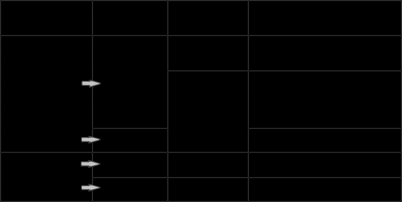
Taking into account the above points, a flow chart showing how to proceed with troubleshooting using the diagnostic trouble code check is shown below. This flow chart shows how to utilize the diagnostic trouble code check effectively, then by carefully checking the results, indicates how to proceed either to diagnostic trouble code troubleshooting or to troubleshooting of problem symptoms.
Diagnostic trouble code check
Makinganote of and clear ing of the diagnostictrouble codes displayed
Symptom confirmation
Problem symptoms exist No problem symptoms exist
Simulation test using the symptom simulation methods
Diagnostic trouble code check

D Diagnostic trouble code displayed
D Problem symptoms exist
Troubleshooting of problem indicated by diagnostic trouble code
D Normal code displayed
D Problem symptoms exist
Troubleshooting of each problem symptom

D Normal code displayed
D No problem symptoms exist
System Normal
If a diagnostic trouble code was displayed in the initial diagnostic trouble code check, it indicates that thetrouble may have occurred in a wire harness or connector in that circuit in the past. Therefore, check the wire harness and connectors (See page IN -21).
The most difficult case in troubleshooting is when there are no problem symptoms occurring. In such cases, a thorough customer problem analysis must be carried out, then simulate the same or similar conditions and environment in which the problem occurred in the customer’s vehicle. No matter how much experience a technician has, or how skilled he may be, if he proceeds to troubleshoot without confirming the problem symptoms he will tend to overlook something important in the repair operation and make a wrong guess somewhere, which will only lead to a standstill. For example, for a problem which only occurs when the engine is cold, or for a problem which occurs due to vibration caused by the road during driving, etc., the problem can never be determined so long as the symptoms are confirmed with the engine hot condition or the vehicle at a standstill. Since vibration, heat or water penetration (moisture) are likely causes for problems which are difficult to reproduce, the symptom simulation tests introduced here are effective measures in that the external causes are applied to the vehicle in a stopped condition.
Important Points in the Symptom Simulation Test: In the symptom simulation test, the problem symptoms should of course be confirmed, but the problem area or parts must also be found out. To do this, narrow down the possible problem circuits according to the symptoms before starting this test and connect a tester beforehand. After that, carry out the symptom simulation test, judging whether the circuit being tested is defective or normal and also confirming the problem symptoms at the same time. Refer to the matrix chart of problem symptoms for each system to narrow down the possible causes of the symptom.

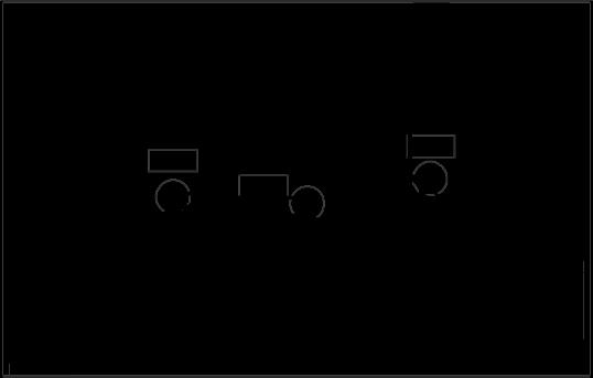
CONNECTORS
Slightly shake the connector vertically and horizontally.
Shake Slightly
WIRE
Slightly shake the wire harness vertically and horizontally. The connector joint, fulcrum of the vibration, and body throughportion are the major areas tobe checked thoroughly.
PARTS
Apply slight vibration with a finger to the part of the sensor considered to be the problem cause and check if the malfunction occurs.
HINT: Applying strong vibration to relays may result in open relays.
Swing Slightly
Vibrate Slightly
Heat the component that is the likely cause of the malfunction with a hair dryer or similar object. Check to see if the malfunction occurs.
NOTICE:
(1)Do not heat to more than 60 ˚C (140 ˚F). (Temperature limit that no damageis doneto the component.)
(2) Do not apply heat directly to parts in the ECU.

Sprinkle water onto the vehicle and check to see if the malfunction occurs.
NOTICE:
(1) Neversprinklewater directly intothe engine compartment, but indirectly change the temperature and humidity by applying water spray onto the radiator front surface.
(2)Never apply water directly onto the electronic components.
(Service hint)
If a vehicle is subject to water leakage, the leaked water may contaminate the ECU. When testing a vehicle with a water leakage problem, special caution must be used.
4□
Turn on all electrical loads including the heater blower, head
lights, rear window defogger, etc. and check to see if the malfunction occurs.
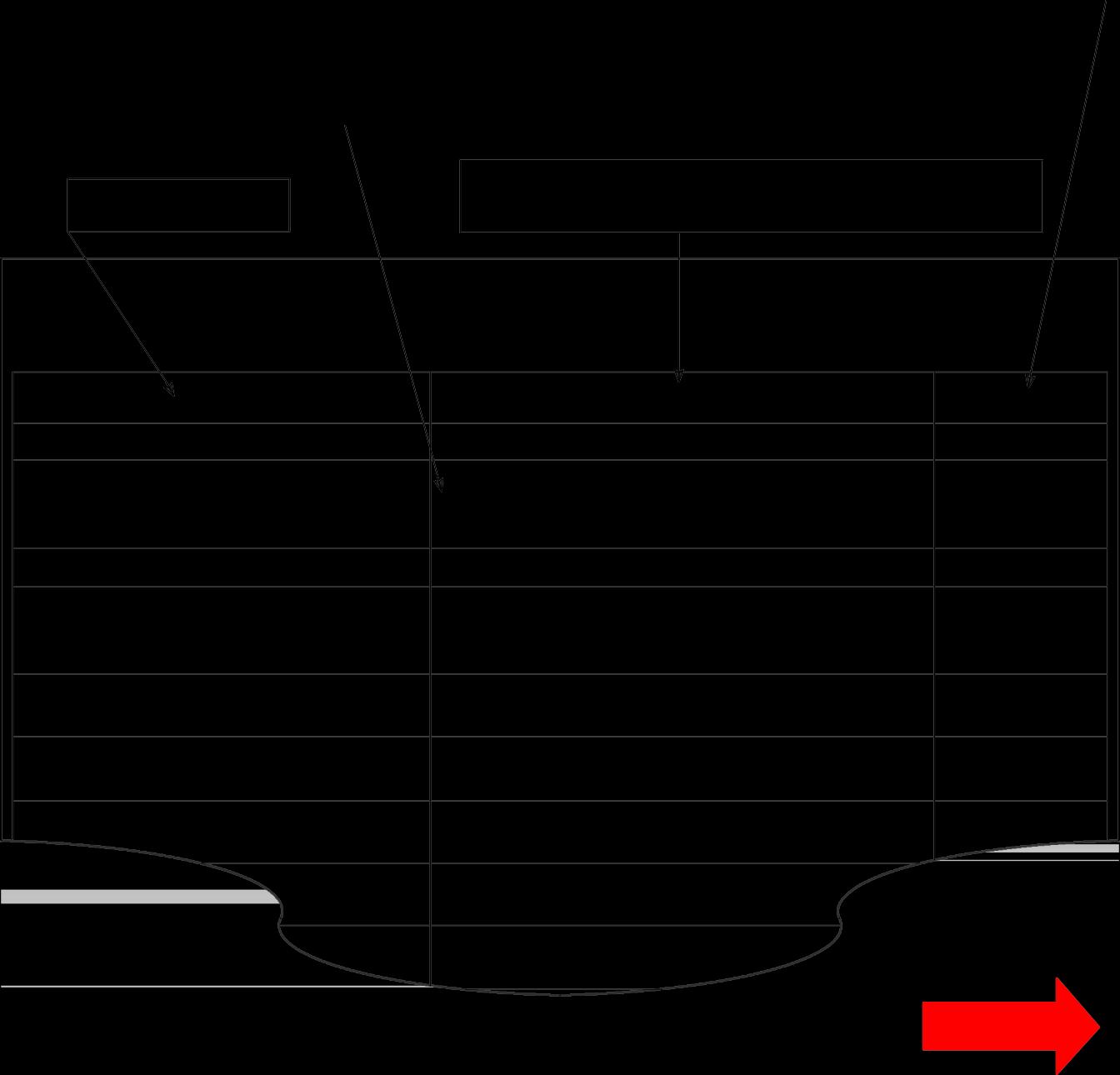
The inspection procedure is shown in the table below. This table permits efficient and accuratetroubleshooting using the diagnostic trouble codes displayed in the diagnostic trouble code check. Proceed with troubleshooting in accordance with the inspection procedure given in the diagnostic chart corresponding to the diagnostictrouble codesdisplayed. Theengine diagnostictrouble codechart isshown belowasanexample.
D DTC No.
Indicates the diagnostic trouble code.
D Page or Instructions
Indicates the page where the inspection procedure for each circuit is to be found, or gives instructions for checking and repairs.
D Detection Item
D Trouble Area
Indicates the suspect area of the problem.
Indicates the system of the problem or contents of the problem.
HINT: Parameters listed in the chart may not be exactly the same as your reading due to the type of instrument or other factors.
If a malfunction code is displayed during the DTC check in check mode, check the circuit for that code listed in the table below. For details of each code, turn to the page referred to under the ”See page” for the respective ”DTC No.” in the DTC chart.
page)
The inspection procedure is shown in the table below. This table permits efficient and accuratetroubleshooting using the diagnostic trouble codes displayed in the diagnostic trouble code check. Proceed with troubleshooting in accordance with the inspection procedure given in the diagnostic chart corresponding to the diagnostictrouble codesdisplayed. Theengine diagnostictrouble codechart isshown belowasanexample.
D DTC No.
Indicates the diagnostic trouble code.
D Page or Instructions
Indicates the page where the inspection procedure for each circuit is to be found, or gives instructions for checking and repairs.
D Detection Item
D Trouble Area
Indicates the suspect area of the problem.
Indicates the system of the problem or contents of the problem.
HINT: Parameters listed in the chart may not be exactly the same as your reading due to the type of instrument or other factors.
If a malfunction code is displayed during the DTC check in check mode, check the circuit for that code listed in the table below. For details of each code, turn to the page referred to under the ”See page” for the respective ”DTC No.” in the DTC chart.

DTC No. (See page) Detection Item Trouble Area
D Open or short in air flow meter circuit
P0100/31 (DI - 12) Air Flow Circuit Malfunction
P0110/24 (DI - 28) Intake Air Temp. Circuit Malfunction
P0115/22 (DI - 31) Water Temp. Circuit Malfunction
P0120/41 (DI - 32) Throttle Position Sensor circuit Malfunction

D Air flow meter
D Engine ECU
D Open or short in intake air temp. sensor circuit
D Intake air temp. sensor
CHK ENG *1 *Memory


D Engine ECU --
D Open or short in water temp. sensor circuit
D Water temp. sensor
D Engine ECU
D Open or short in throttle position sensor circuit
D Throttle position sensor
D Engine ECU
D Open or short in Oxygen sensor circuit
D Oxygen sensor


The suspect circuits or parts for each problem symptom are shown in the table below. Use this table to troubleshooting the problem when a ”Normal” code is displayed in the diagnostic trouble code check but the problem is still occurring. Numbers in the table indicate the inspection order in which the circuits or parts should be checked.
HINT:
When the problem is not detected by the diagnostic system even though the problem symptom is present, it is considered that the problem is occurring outside the detection range of the diagnostic system, or that the problem is occurring in a system other than the diagnostic system.
D Page
Indicates the page where the flow chart for each circuit is located.
D Circuit Inspection, Inspection Order Indicates the circuit which needs to be checked for each problem symptom. Check in the order indicated by the numbers.
D Problem Symptom
D Circuit or Part Name Indicates the circuit or part which needs to be checked.
How to read and use each page is shown below.
D Diagnostic Trouble Code No. and Detection Item
D Circuit Description
The major role and operation, etc. of the circuit and its component parts are explained.
DTC 43 Starter Signal Circuit
CIRCUIT DESCRIPTION
When the engine is cranked, the intake air flow is slow, so fuel vaporization is poor. A rich mixture is these fore necessary in order to achieve good startability. While the engine is being cranked, the battery positive voltage is applied to terminal STA of the ECU.
WIRING DIAGRAM

D Indicates the diagnostic trouble code, diagnostic trouble code set parameter and suspect area of the problem.
D Wiring Diagram
This shows a wiring diagram of the circuit. Use this diagram together with ELECTRICAL WIRING DIAGRAM to thoroughly understand the circuit.
Wire colors are indicated by an alphabetical code.
B = Black, L = Blue, R = Red, BR = Brown, LG = Light Green, V = Violet, G = Green, O = Orange, W = White, GR = Gray, P = Pink, Y = Yellow
The first letter indicates the basic wire color and the second letter indicates the color of the stripe.
How to read and use each page is shown below.
D Diagnostic Trouble Code No. and Detection Item
D Circuit Description
The major role and operation, etc. of the circuit and its component parts are explained.
DTC P0325/52 Knock Sensor Circuit Malfunction
CIRCUIT DESCRIPTION
Knock sensor are fitted to the cylinder block to detect engine knocking. This sensor contains a piezoelectric element which generates a voltage when it becomes deformed, which occurs when the cylinder block vibrates due to knocking.
P0325/52
No knock sensor 1 signal to engine ECU with engine speed between 1,700 rpm and 5,200 rpm
sensor circuit ess) D Open or short in knoc D Knock sensor (Loosen D Engine ECU
WIRING DIAGRAM
D Indicates the diagnostic trouble code, diagnostic trouble code set parameter and suspect area of the problem.
D Wiring Diagram
This shows a wiring diagram of the circuit. Use this diagram together with ELECTRICAL WIRING DIAGRAM to thoroughly understand the circuit.
Wire colors are indicated by an alphabetical code.
B = Black, L = Blue, R = Red, BR = Brown, LG = Light Green, V = Violet, G = Green, O = Orange, W = White, GR = Gray, P = Pink, Y = Yellow
The first letter indicates the basic wire color and the second letter indicates the color of the stripe.
D Indicates the position of the ignition switch during the check

LOCK Ignition Switch LOCK (OFF)

START Ignition Switch START ON Ignition Switch ON ACC Ignition Switch ACC
INSPECTION PROCEDURE LOCK KNK E 6 Connec tor
D Inspection Procedure
Use the inspection procedure to determine if the circuit is normal or abnormal, and, if it is abnormal, use it to determine whether the problem is located in the sensors , actuators , wire harness or ECU.
Check continuity between terminal KNK of ECM connect or and body ground.


PREPARATION :
(a) Remove the glove compartment ( See page F I 37) (b) D is connect the E 6 connector of ECM.
CHECK:
Measure resistance between terminal K N K of E C U connector and body ground.
OK:
Resistance: 1M. or higher
Go to step 3.
Check knock sensor ( See page F I 34)
Replace knock sensor.
D Indicates the place to check the voltage or resistance.
D Indicates the connector position to checked, from the front or back side.

Check from the connector back side. ( with harness )

Check from the connector front side. ( without harness ) In this case, care must be taken not to bend the terminals
D Indicates the condition of the connector of ECU during the check KNK KNK E 6 Connector E 6 Connector

Connector being checked is connected.

Connect or being checked is disconnected.


S For troubleshooting, diagnostic trouble code charts or problem symptom charts are provided for each circuit with detailed inspection procedures on the following pages.
S When all the component parts, wire harnesses and connectors of each circuit except the ECU are found to be normal in troubleshooting, then it is determined that the problem is in the ECU. Accordingly, if diagnosis is performed without the problem symptoms occurring, the instruction will be to check and replace the ECU, even if the problem is not in the ECU. So always confirm that the problem symptoms are occurring, or proceed with inspection while using the symptom simulation method.
S The instructions ”Check wire harness and connector” and ”Check and replace ECU” which appear in the inspection procedure, are common and applicable to all diagnostic trouble codes. Follow the procedure outlined below whenever these instructions appear.
OPEN CIRCUIT:
This could be due to a disconnected wire harness, faulty contact in the connector, a connector terminal pulled out, etc.
HINT:
S It is rarely the case that a wire is broken in the middle of it. Most cases occur at the connector. In particular, carefully check the connectors of sensors and actuators.
S Faulty contact could be due to rusting of the connector terminals, to foreign materials entering terminals or a drop in the contact pressure between the male and female terminals of the connector. Simply disconnecting and reconnecting the connectors once changes the condition of the connection and may result in a return to normal operation. Therefore, in troubleshooting, if no abnormality is found in the wire harness and connector check, but the problem disappears after the check, then the cause is considered to be in the wire harness or connectors.
SHORT CIRCUIT:
This could be due to a short circuit between the wire harness and the body ground or to a short inside the switch etc.
HINT:
When there is a short between the wire harness and body ground, check thoroughly whether the wire harness in the body or is clamped properly.


(a) Disconnect the connectors at both ECU and sensor sides.
(b) Measuretheresistance betweenthe applicableterminals of the connectors.
Resistance: 1 Ω or less
HINT:
S Measure the resistance while lightly shaking the wire harness vertically and horizontally.
S When tester probes are inserted into a connector, insert the probes from the back. For waterproof connectors in which the probes cannot be inserted from the back, be careful not to bend the terminals when inserting the tester probes.
(a) Disconnect the connectors at both ends.
(b) Measuretheresistance betweenthe applicableterminals of the connectors and body ground. Be sure to carry out this check on the connectors on both ends.
Resistance: 1 MΩ or higher
HINT:
Measure the resistance while lightly shaking the wire harness vertically and horizontally.
(a) Disconnect the connectors at both ends.
(b) Check for rust or foreign material, etc. in the terminals of the connectors.
(c) Check crimped portions for looseness or damage and check if the terminals are secured in lock portion.
HINT:
The terminals should not come out when pulled lightly.
(d) Prepareatestmaleterminalandinsertit inthefemaleterminal, then pull it out.
NOTICE:
Whentesting a gold-platedfemale terminal, always use a gold-platedmaleterminal.
HINT:
When the test terminal is pulled out more easily than others, there may be poor contact in that section.


2
3

When inserting tester probes into a connector, insert them from the rear of the connector. When necessary, use mini test leads. For water resistant connectors which cannot be accessed from behind, take good care not to deform the connector terminals.
For the open circuit in the wire harness in Fig.1, perform ”(a) Continuity Check” or ”(b) Voltage Check” to locate the section.
(a) Check the continuity.
(1)
Disconnect connectors ”A” and ”C” and measure the resistance between them.
In the case of Fig.2, Between terminal 1 of connector ”A” and terminal 1 of connector ”C” → No continuity (open)
Between terminal 2 of connector ”A” and terminal 2 of connector ”C” → Continuity
Therefore,itisfoundoutthatthere isan opencircuit between terminal 1 of connector ”A” and terminal 1 of connector ”C”.
(2) Disconnect connector ”B” and measure the resistance between them.
In the case of Fig.3,
Between terminal 1 of connector ”A” and terminal 1 of connector ”B1” → Continuity
Between terminal 1 of connector ”B2” and terminal 1 of connector ”C” → No continuity (open)
Therefore,itisfoundoutthatthere isan opencircuit between terminal 1 of connector ”B2” and terminal 1 of connector ”C”.
INTRODUCTION -- HOW TO TROUBLESHOOT ECU CONTROLLED SYSTEMS
(b) Check the voltage.
In a circuit in which voltage is applied (to the ECU connector terminal), an open circuit can be checked for by conducting a voltage check.
As shown in Fig.4, with each connector still connected, measure the voltage between body ground and terminal 1 of connector ”A” at the ECU 5V output terminal, terminal 1 of connector ”B”, and terminal 1 of connector ”C”, in that order.
If the results are:
5V: Between Terminal 1 of connector ”A” and Body Ground
5V: Between Terminal 1 of connector ”B” and Body Ground
0V: Between Terminal 1 of connector ”C” and Body Ground
Then it is found out that there is an open circuit in the wire harness between terminal 1 of ”B” and terminal 1 of ”C”.


If the wire harnessis ground shorted asin Fig.5, locate the section by conducting a ”continuity check with ground”.
Check the continuity with ground. (1)
Disconnect connectors ”A” and ”C” and measure the resistance between terminal 1 and 2 of connector ”A” and body ground.
In the case of Fig.6
Between terminal 1 of connector ”A” and body ground → Continuity (short)
Between terminal 2 of connector ”A” and body ground → No continuity
Therefore, it is found out that there is a short circuit between terminal 1 of connector ”A” and terminal 1 of connector ”C”.
INTRODUCTION -- HOW TO TROUBLESHOOT ECU CONTROLLED SYSTEMS IN -25

(2)
Disconnect connector ”B” and measure the resistance between terminal 1 of connector ”A” and body ground, and terminal 1 of connector ”B2” and body ground.
Between terminal 1 of connector ”A” and body ground → No continuity Between terminal 1 of connector ”B2” and body ground → Continuity (short) therefore, it is found out that there is a short circuit between terminal 1 of connector ”B2” and terminal 1 of connector ”C”.
First check the ECU ground circuit. If it is faulty, repair it. If it is normal, the ECU could be faulty, so replace the ECU with a known good one and check if the symptoms appear.


(1) Measure the resistance between the ECU ground terminal and the body ground.
Resistance: 1 Ω or less
(2) Disconnect the ECU connector, check the ground terminals on the ECU side and the wire harness side for bend and check the contact pressure.
INTRODUCTION -- TERMS
Abbreviations
A/C Air Conditioner
A/T Automatic Transmission
BTDC Before Top Dead Center
ECU Electronic Control Unit
EFI Electronic Fuel Injection
EGR Exhaust Gas Recirculation
EVAP Evaporative Emission Control
FIPG Formed In Place Gasket
FL Fusible Link
M/T Manual Transmission
IG Ignition
IIA Integrated Ignition Assembly
ISC Idle Speed Control
J/B Junction Block
O/S Oversize
PCV Positive Crankcase Ventilation
SSM Special Service Materials
SST Special Service Tools
SW Switch
TDC Top Dead Center
TWC Three - Way Catalyst
VSV Vacuum Switching valve
w/ With
w/ o Without
Meaning