
Hydronic
Fan
Air flow: 510~2380 m3/h
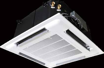
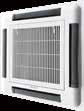
42GWC
Cassette
Coil Unit
I n 1998 , Time magazine named D r Carrie r one o f i ts 20 mos t in f luen t ial builder s and t i t an s o f t he 20 t h c en t ur y
Carrier is a leading global pro v ider o f innova t i v e H VA C , re f rigera t ion , f ire , securi t y and building au t oma t ion t e c hnol o gie s. S uppor t ed by t he iconi c Carrier name , t he compan y ’ s por tf olio includes indus t ryleading brand s such as Carrie r, K idde , E dward s, Lenel S 2 and A u t oma t ed Logic Carrie r ’ s busine s se s enable modern li f e , delivering e f f i c ienc y, sa f e t y, s ecuri t y, com f or t, produc t ivi ty and s u st ainabili ty across a wide

range o f residen t ial , commercial and indu st rial applica t ion s.

Model number Nomenclature
Unit body:
42 GWC 003 02 0 0 5 CARS
Manufacture Code
CARS: Manufacture Code
Product Re-design Key
5: 5rd Modify
Unit Packing
0: Standard Packing
Option
A: Export Standard Unit
B: Export Unit With Valve Kit
Electrics Power
0 2 : 220v - 1ph - 50hz
0C: 230v - 1ph - 60hz
0K: DC Motor (0~10v) (Not Available For 010/012/014)
Unit Size (Cooling Capacity kw)
003: 3.2 kW 004: 4.0 kW
005: 5.2 kW 006: 6.25 kW
008: 7.8 kW 010: 9.1 kW
012: 10.9 kW 014: 12.6 kW
Model Letters
GWC: Hydraulic Cassette - 2 Pipe
Product Series
42: Fan Coil Unit
Manufactory Code
CARS: Manufacture Code
Product Re-design Key
5: 5rd Modify
Unit Packing
0: Standard Packing
Option
A: Export Standard Panel Kit, Without Wireless Remote Control
Electrics Power
00: No Power (For Hydraulic Cassette Only)
Unit Size
00L : Large Chassis (Used For 42GWC005/006/008)
00S: Small Chassis (Used For 42GWC003/004)
00X: X-large Chassis (Used For 42GWC010/012/014)
Model Letters
GWC: Hydraulic Cassette
Product Series
42: Fan Coil Unit
2
00 0 0 5 CARS
Compact design for easy installation.
Four-way air distribution gives individual comfort while for localized control each diffuser may be adjusted or even shut down completely.
The unique design of centrifugal fan ensures the quiet running of the unit. This thoroughly eliminates the bothering throttle noise inside the room.
High-performance condensate drain pump.
Return air enters the cassette unit through a large grille, cleaned by an easily removable, washable filter, and then keep the room air fresh through constant circulation.
The Special design of the diffuser ensures rapid blending of the supply and room air. A Large LCD screen thermostat is optioned.
Motor and Fan
Optimized designed centrifugal fan design for 42GWC. High efficiency.
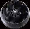
Quite running with anti-vibration pads of motor.
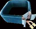
Coil
Optimized designed 7 mm coil.
Air return grille and filter
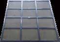
The filter inside the air return grille can be easily removed and washed. The front panel and frill of the unit are designed with stylish appearance makes it suitable to match various room decorations.
Features 3
High performance condensate drain pump inbuilt the unit. Drain out the condensate water quietly. Keeps running when the unit standby.
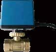
To avoid the leakage of the condensate water, it’s recommended to install the twoway valve or three-way valve in the water system.
Compared with conventional AC FCU, BLDC FCU can stepless modulating the airflow, and have big advantages in efficiency, noise and energy saving.
Set precision of THT420 thermostat for 42GWC BLDC is up to 0.5℃.
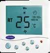
42GWC BLDC can not only match THT420 thermostat, but also be compatible with common 0~10V thermostat on the market.

The unit can provide stand alone or group control and can be connected to the room control unit (RCU).

The MODBUS type controller is equipped with RS485 communication interface, supports standard Modbus communication protocol, and facilitates access to the building automation (BA) system.
THT420 thermostat have timing function and convenient to set start and turn off time. Using IPM drive module, it has protections of overcurrent, overvoltage, undervoltage, rotor locking, overspeed, etc.
Accessories (Optional)
4
Condensate drain pump
TMS810R
Electric two-way ball valve
Brushless DC motor (option)
THT420 series
BLDC motor
Features and applications of brushless DC motor FCU
Compared to traditional fan coils, brushless DC motor fan coils are featured by energy-saving, supreme comfort, intelligent control and reliability with up-to-date brushless DC stageless motor and advanced control technology. Carrier brushless DC fan coil is ideal choice for buildings seeking for both green and comfort.
The BLDC fan coil offers an average energy saving of 50% or more, compared to conventional AC fan coil units. In automatic mode, energy consumption can be reduced even further as the unit’s advanced intelligent control technology gradually adjusts the motor speed for optimal energy saving. This adds up to a significant reduction in the total HVAC system running cost.
Conventional AC fan coil units regulate room temperature by water flow control and fan speed, which is set at high, medium, or low. Considerable fluctuation in actual room temperature is inevitable and poor humidity control is a common problem. Through its AC/DC converter, the BLDC fan coil linearly regulates motor speed using pulse-width modulation. Airflow and water flow are regulated according to room load change or a customized temperature/humidity control scheme. In contrast to the traditional fan coil unit, the BLDC fan coil delivers precise temperature and humidity control in accordance with actual demand and is able to stabilize the room temperature to within ± 0.5°C in automatic mode.
Super-quiet operation
The 42GWC series fan coil unit was developed for quiet operation. Engineered with advanced low-noise fan technology, it is manufactured with state-of-art craftsmanship, adopting a large fan wheel structure and NSK bearings. Carbon brush noise, unavoidable in conventional AC fan coil units, is eliminated in the BLDC fan coil. Most of the time, the unit is operating at medium or low speeds, where quiet operation is all the better.
Flexible and convenient
With factory default settings for both the fan coil, the 42GWC BLDC fan coil unit is ready to operate by simply wiring the fan coil and thermostat.
Safe and reliable
The 42GWC fan coil comes with a power factor correction (PFC) module for surge protection and improved efficiency. The high voltage power module ensures safe and stable operation under a wide range of power environment. Overload and over-current protection prevents motor burnout.
5
Power Consumption Comparison 200 400 600 800 1000 Ordinary AC Motor 0 10 20 30 40 50 60 70 80 90 W Power Input Air Flow m 3 /h Between AC Motor and DC Motor Time Set Temperature Room Temperature DC brushless Motor Supreme comfort Significant energy saving
Technical Data
Note: 1.Cooling Conditions: 27℃ DB/19.5℃ WB entering air temperature, 7℃ entering water and 5℃ temperature rise.
2. Heating Conditions: 21℃ entering air temperature, 60℃ entering water temperature,the same water flow as the cooling conditions.
3.Sound level is tested per GB/T 19232-2019.
4.Water pressure drop shown in above table doesn't include valve pressure drop.
5.FCEER means fan coil cooling energy efficiency ratio and FCCOP means fan coil heating coefficiency of performance, defined per GB/T 19232-2019.
Operating Limits
If the room temperature goes down to 0℃, it is advisable to empty the water circuit to avoid damage caused by frozen.
6
Water Circuit Water Circuit Water Circuit Maximum water-side pressure 1400kPa Maximum temperature 5℃ Nominal single-phase vohage 220V, 50Hz Minimum entering water temperature 4℃ Maximum temperature 32℃ Operating voltage limits 198V~242V Maximum entering water temperature 80℃ Model 003 004 005 006 008 010 012 014 Nominal Air flow m3/h ( H ) 510 680 850 1020 1360 1700 2040 2380 ( M ) 420 560 650 780 1050 1300 1570 1830 ( L ) 350 460 520 600 800 1010 1210 1410 Cooling Capacity W 3200 4000 5200 6250 7800 9100 10900 12600 Heating Capacity W 4830 6000 7850 9450 10800 13700 16300 18900 Power Input- AC motor W 35 55 65 80 114 150 160 190 Power Input - DC motor W 15 20 23 29 55 / / / Noise Level dB ( A ) ( H ) 38 41 40 41 45.5 48 50 52 ( M ) 34 38 36 37 41 45 47 49 ( L ) 31 34 33 34 39 41 44 46 Water Flow l/min 9.2 11.5 14.9 17.9 22.4 26.1 31.2 36.1 Water Pressure Drop KPa 25 22 24 30 40 30 35 50 Water Connection inch Rc 3/4" Rc 3/4" Rc 3/4" Rc 3/4" Rc 3/4" Rc 3/4" Rc 3/4" Rc 3/4" Unit Body Dimension mm 650*650 850*850 1050*1050 Panel Dimension mm 570*570*250 730*730*290 930*930*290 Panel Weight Kg 2.5 4.5 6.5 Unit Body Weight Kg 25 26 33 43.5 79/120 65/98 71/107 67/102 58/80 54/81 59/88 54/82 FCEER/FCCOP(AC)w/w 159/240 156/234 168/253 152/230 104/144 / / / FCEER/FCCOP(DC)w/w
Physical Dimensions
Electrical Data
7 42GWC 003-004 without ball valve 42GWC 005-008 without ball valve 42GWC 005-008 with ball valve 250 280 616 580 148 183 205 125 580 RC3/4 650 650 380 20 20 35 60 100 Bypass Flash air Bypass 250 280 616 580 20 125 645 RC3/4 650 650 380 60 20 580 100 Flash air 35 35 148 183 205 RC3/4 20 305 155 100 440 776 850 850 450 735 735 20 35 60 Bypass Flash air 223 188 245 305 155 100 440 776 735 730 RC3/4 20 850 450 850 20 35 60 Bypass Flash air 223 188 245 640 976 935 1050 650 640 976 935 935 1050 650 42GWC 003-004 with ball valve Performance Models 003 004 005 006 008 010 012 014 Power Input (AC) W 35 55 65 80 114 150 160 190 Power Input (DC) W 15 20 22 28 63 / / / Current (AC) A 0.16 0.25 0.3 0.37 0.52 0.7 0.74 0.88 Current (DC) A 0.07 0.09 0.1 0.13 0.29 / / / RC-3/4" 205 165 255 20 305 35 155 Bypass Flash air Bypass Flash air 100 100 155 100 42GWC 010-014 without ball valve 42GWC 010-014 with ball valve 1050 935 1050 20 RC-3/4" 205 165 255 305 35 Note: Power input data and current data in above table is based on 220V-1Ph-50Hz.
42GWC 003-014 AC
Attention: Any warranty is declined in case of field changes of factory wiring and settings
8
Wiring Diagram
Orange ( L ) Brown ( M ) Yellow ( H ) Red R2 R1 JP12 M ~ JP14 JP6 CPU Yellow/Green M JP8 JP2 JP4 JP7 JP1 Blue Black 3 4 5 2 1 TB N L Black JP3 Thermostat VALVE ON H M L N L S N L Legend : JP1 ---Transformer JP2 ---Power supply JP3 ---3-way valve JP4 ---Drainage pump JP12 ---220VAC
signal JP14 ---Float switch Factory
---Field wiring JP10 JP9
input
wiring
9
003-008 DC Legend : Factory Wiring Field Wiring Terminal Block Indoor Fan Motor Water Valve Float Valve Drain Pump IDF CV1 FS PS Cable color : Brown Blue Black Gray Red White Yellow Yellow-Green BN BU BK GY RD WH YE GNYE Y-G FS N L CV1 S BK BN BU RD BU Pump Control Board Driver Board PCB W V U FAN1 PE1 N V G L IDF1 N L PUMP DI PS N L V G 5 User wiring 220V-1Ph-50Hz Protective earth Live line V control signal G control signal Valve ON Neural line Attention: Any warranty is declined in case of field changes of factory wiring and settings
Wiring Diagram
42GWC
Ordering Information
When ordering, please clearly indicate product information based on product nomenclature, including unit model, power-supply, options etc.
Please read instruction manual shipped with unit thoroughly before starting installation. Choose proper installation position and comply with national and local safety code requirements.
If unit without valve is ordered, please local-supply and mount motorized valve on the unit after the unit installation. If unit with valve is ordered, the valve will be mounted to unit in factory.
High performance condensate drain pump is inbuilt in the unit, with draining distance 200mm higher than unit top.
If it is necessary to discharge the condensate from a level above 200 mm, install an auxiliary water discharge pump and float valve. ·The float valve is recommended to stop the flow switch if there is a fault at the auxiliary pump.
Please refer to instruction manual for water connection, motorized valve and control wiring etc.
Please refer to instruction manual for fresh air renewal and conditioned air supply to an adjacent room, otherwise condensate may drip.
Cleaning and maintenance operations must be carried out by specially trained personnel. Before performing any service or maintenance operations, turn OFF the main power switch.
Please refer to instruciton manual for more informations.
10
The Manufacturer reserves the right to change any produt specifications without prior notices
Version:
Supersede:
Effective Date:
CAT_42GWC_E-202010_06
CAT_42GWC_E-1909_05
