Architecture Student at Thomas Jefferson University
About Me
Spiritual Connections
Designed by Carrie Finfrock, Dean Palahniuk, & Mauricio Vivero, Fall 2024
Northern Liberties Multimedia Library
Designed by Carrie Finfrock, Fall 2023
Designed by Carrie Finfrock & Alex Martz, Spring 2024
Draw by Carrie Finfrock, Mauricio Vivero & Dean Palahniuk, Fall 2024
Garden Wall
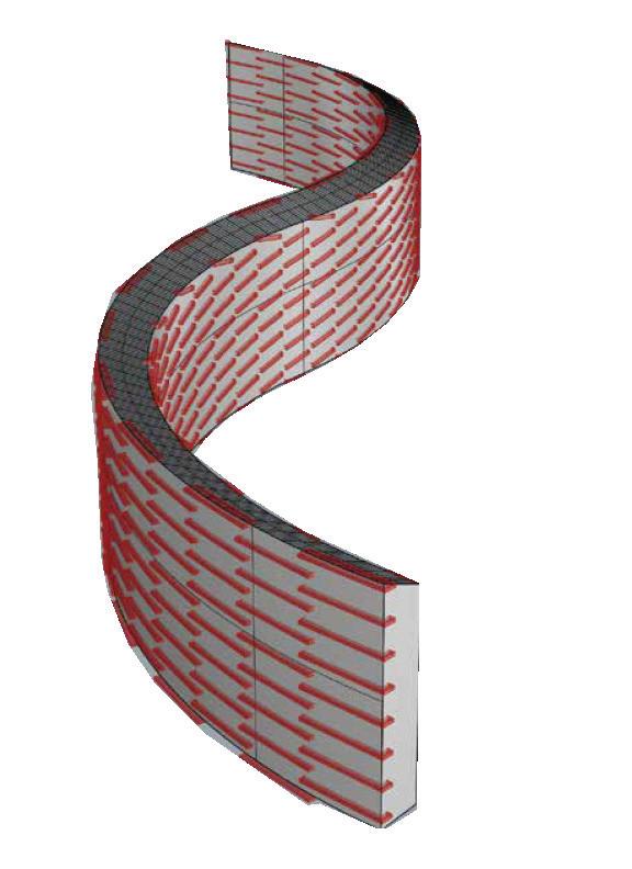
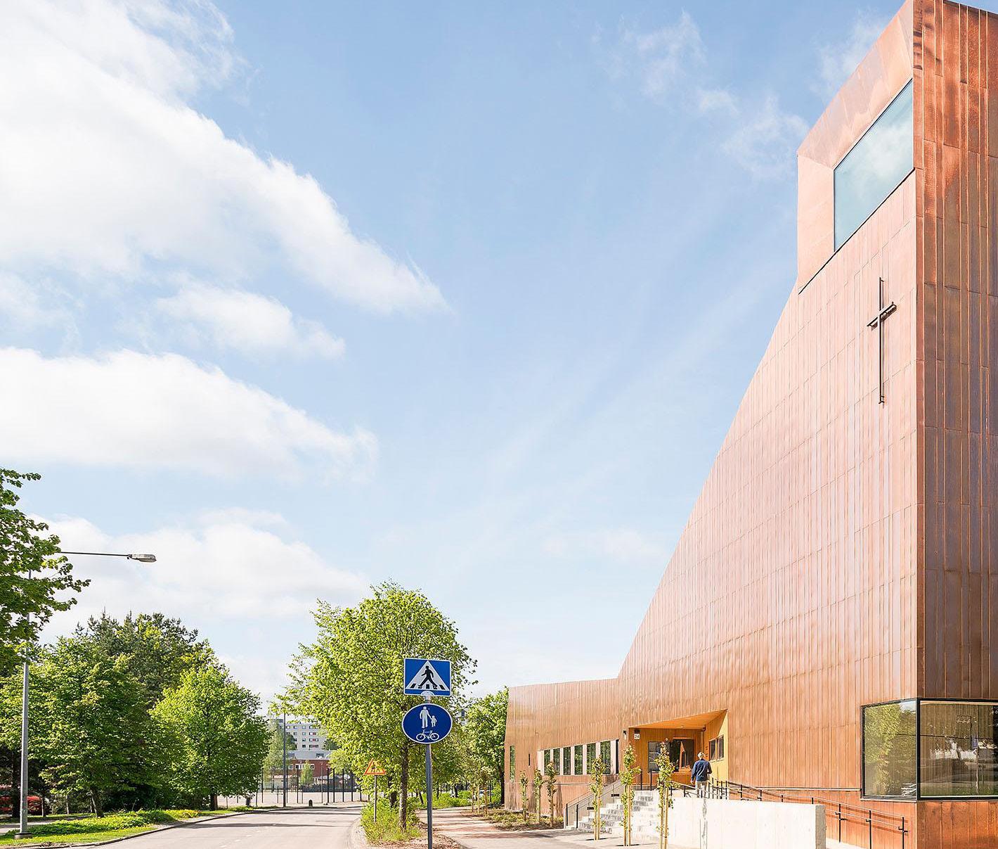
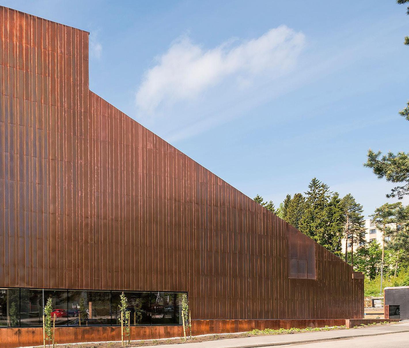
Suvela Chapel Modeling Activity
About Me:
Carrie Finfrock
Fourth year Architecture Student
Born and raised in Columbus, Ohio, I am currently a fourth year architecture student at Thomas Jefferson University, Philadelphia, Pennsylvania. I have experience designing in Revit, Rhino, AutoCAD, and Adobe software programs. My Midwestern background has instilled in me a strong work ethic and years of experience in customer relations. My goal is to obtain experience in all aspects of architecture and in designing a variety of different structures.
Education:
Thomas Jefferson University, Philadelphia, PA Bachelor of Architecture, Anticipated Graduation May 2026
Bishop Watterson High School, Columbus Ohio Class of 2021
Experience:
Thomas Jefferson University, Dean’s Office for the College of Architecture & the Built Environment Student Worker March 2024 to Present
Assists the Dean’s staff with organizing admitted student events and other administrative duties.
Westerville Parks and Recreation Camp Counselor May 2024-August 2024
Facilitated several different games and activities for children ages 9-12
Columbus Zoo & Aquarium, Food and Beverage Staff/ Supervisor June 2019 - August 2023
Operated and supervised Wild Burger food stand and food and beverage carts.
Awards:
Nexus Scholarship Dean’s List
Affiliation:
Nexus Scholarship Advisory Committee
American Institute of Architecture Students Students for Historical Preservation
Softwares:
AutoCAD
Adobe:
Enscape
Grasshopper
Lumion
Rhino
Revit
Sketchup
Twinmotion
MS Office Contact:
Linkedin ULR:
O1.
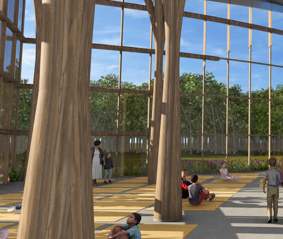
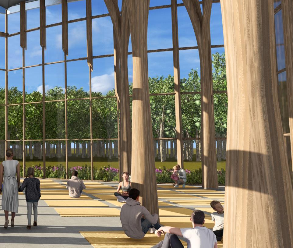
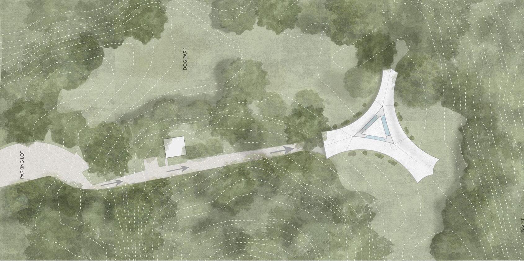
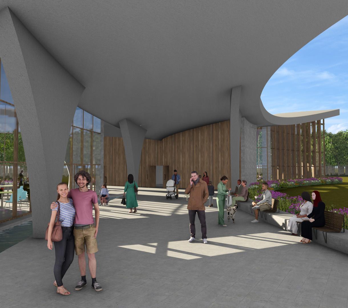
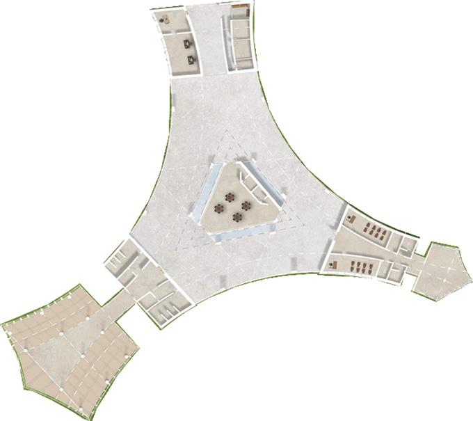
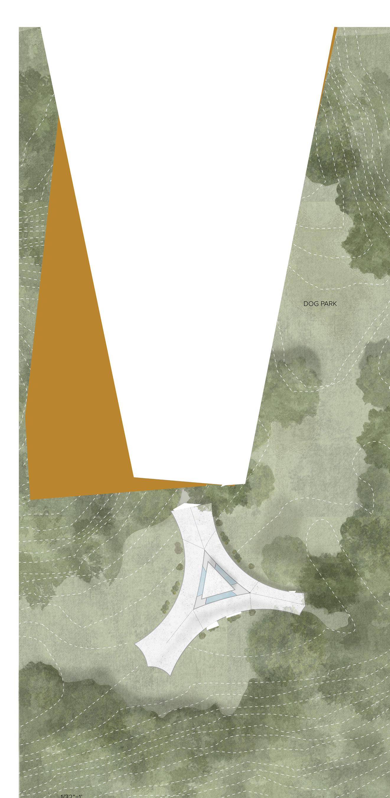
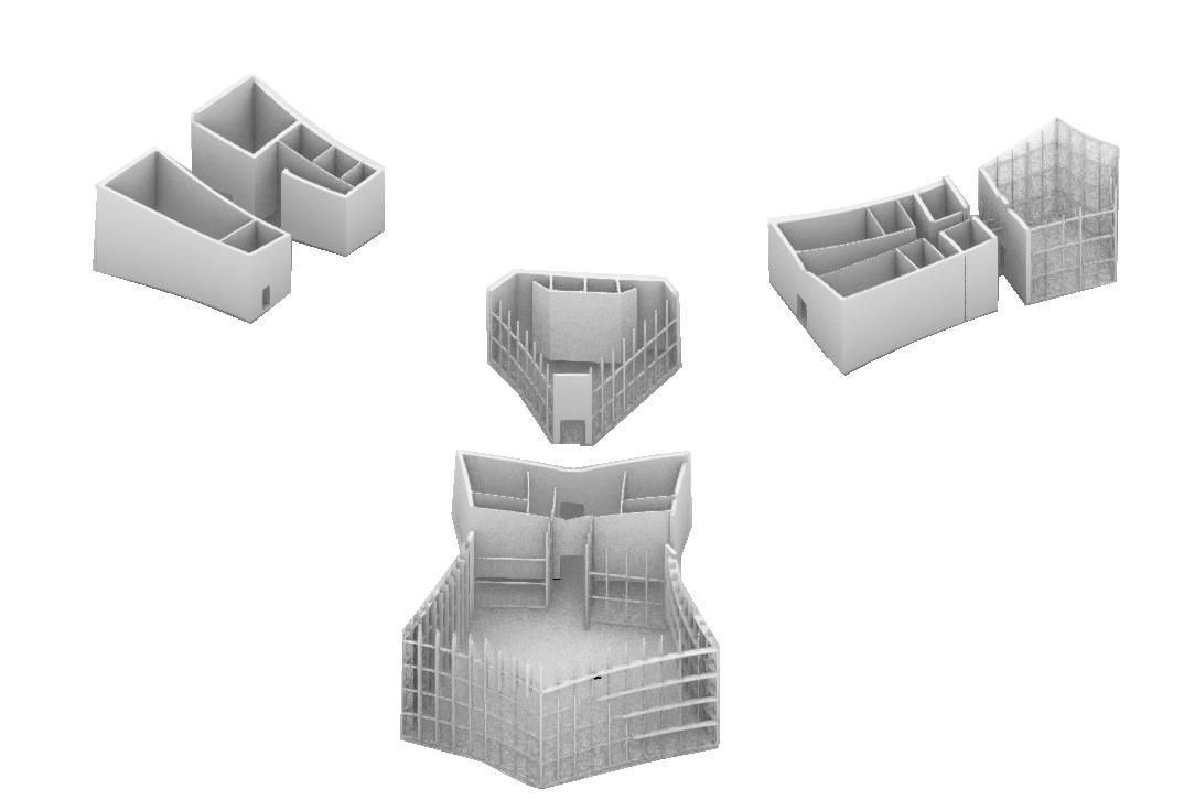
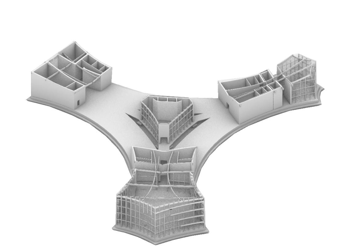
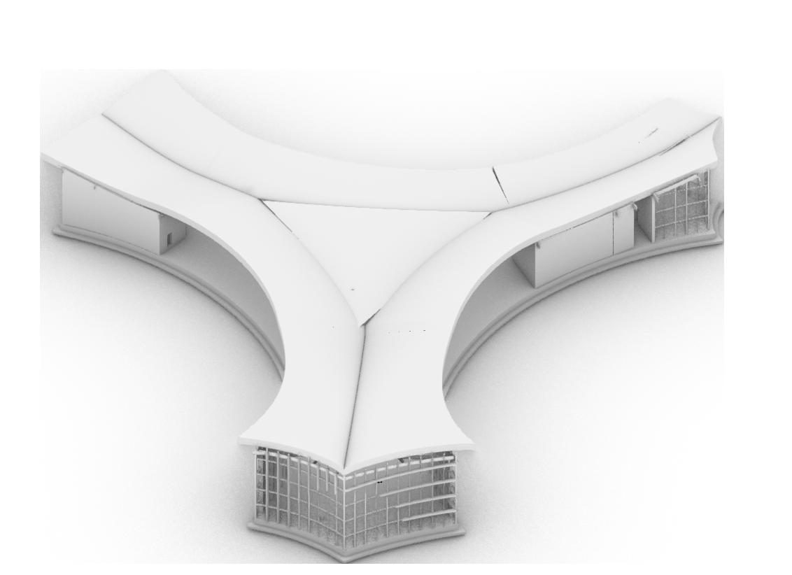
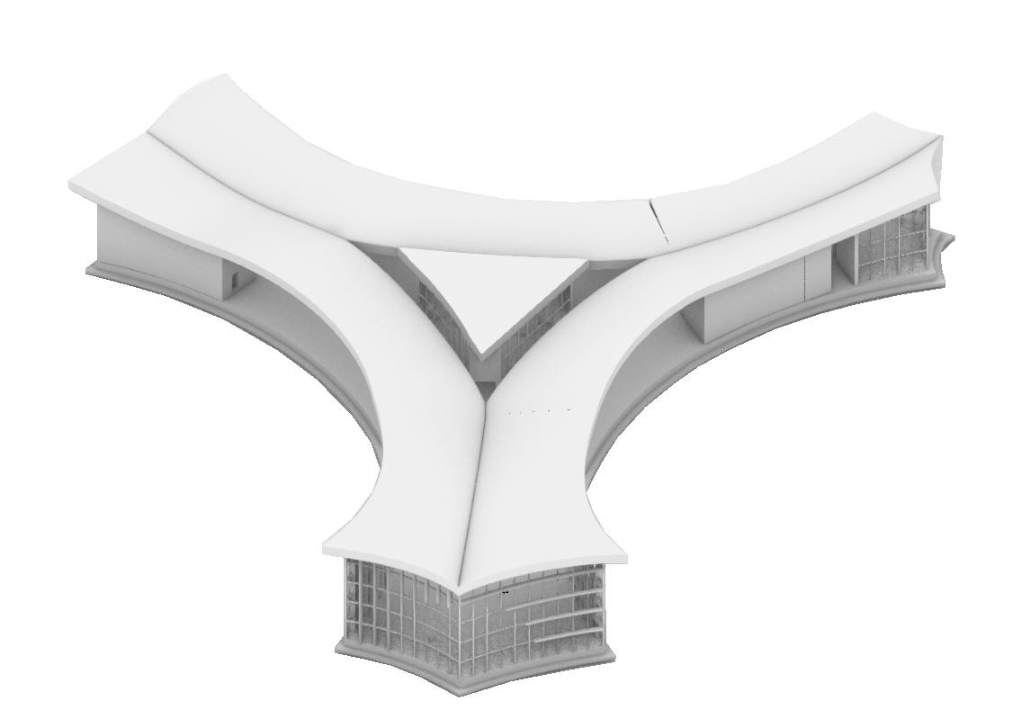
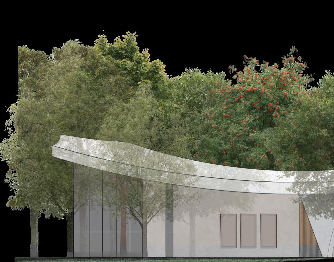
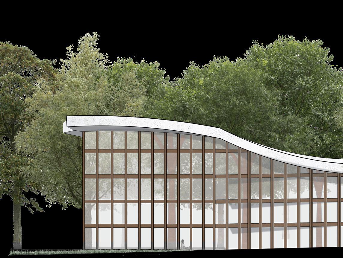
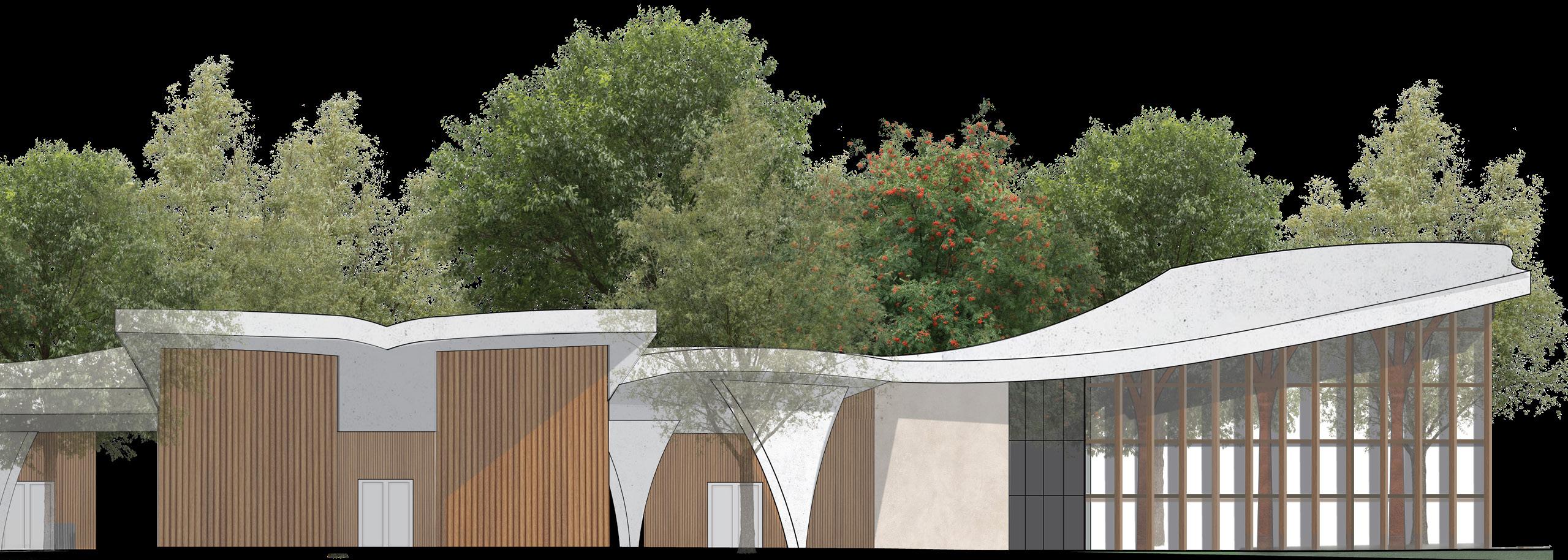
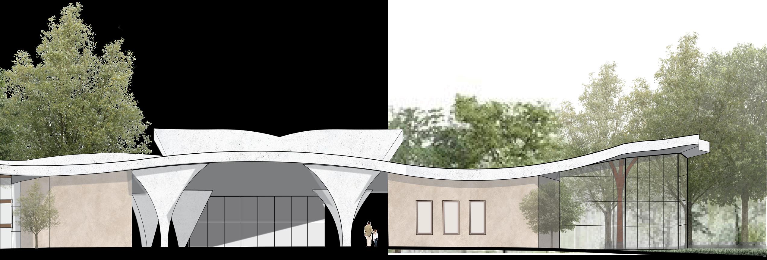
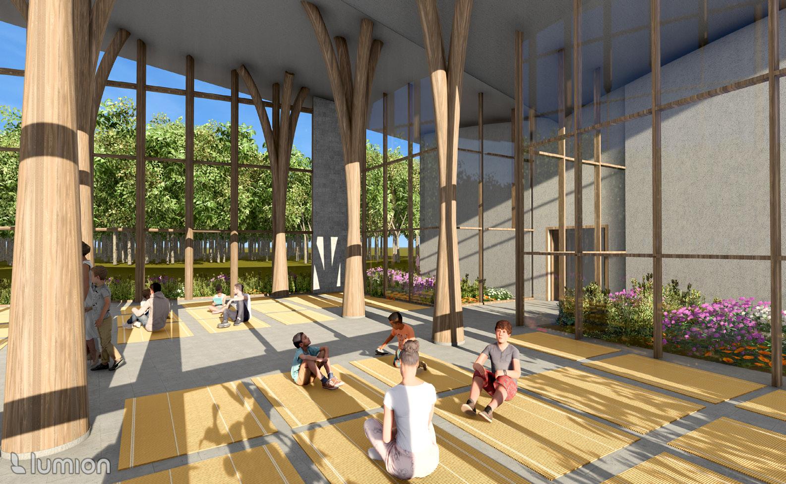
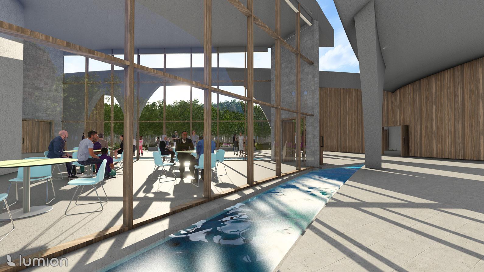
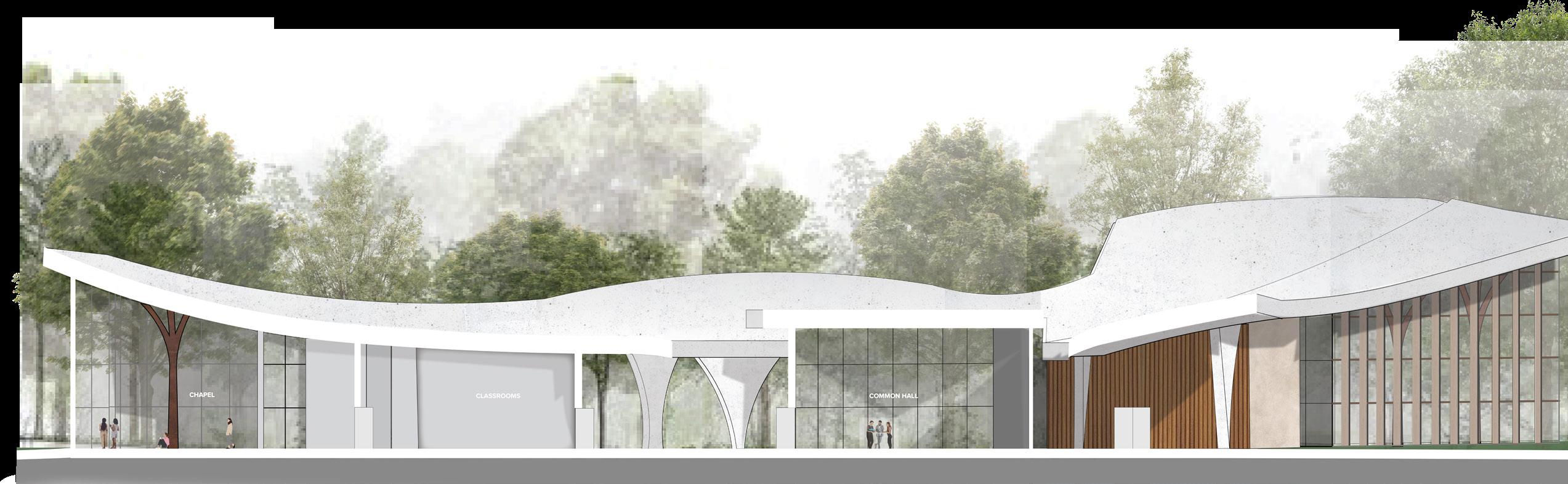
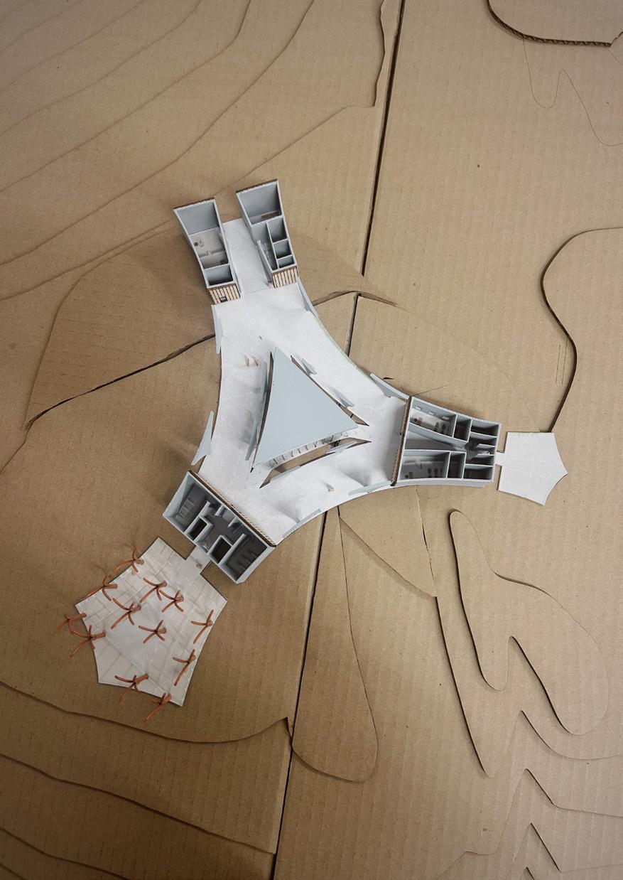
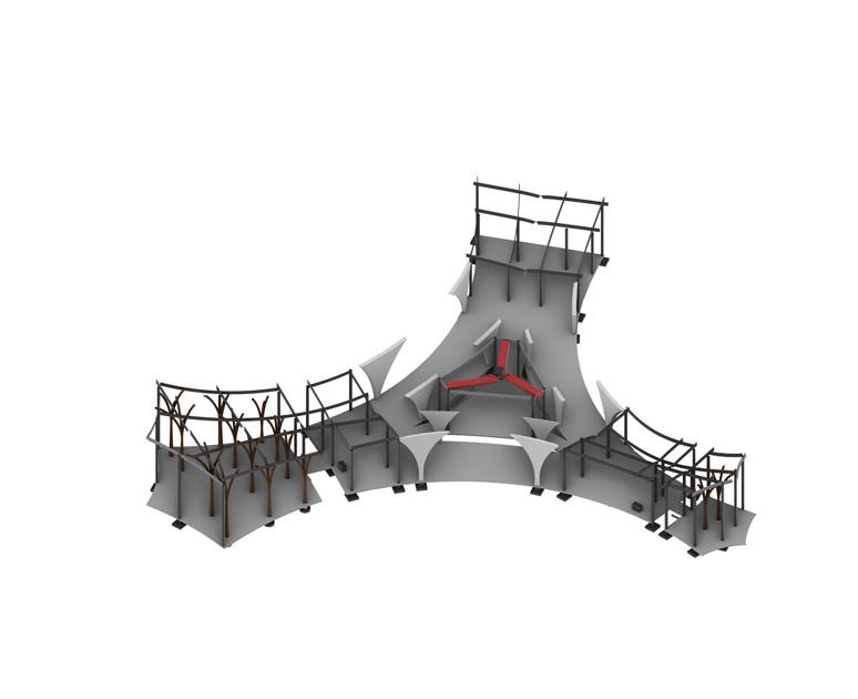
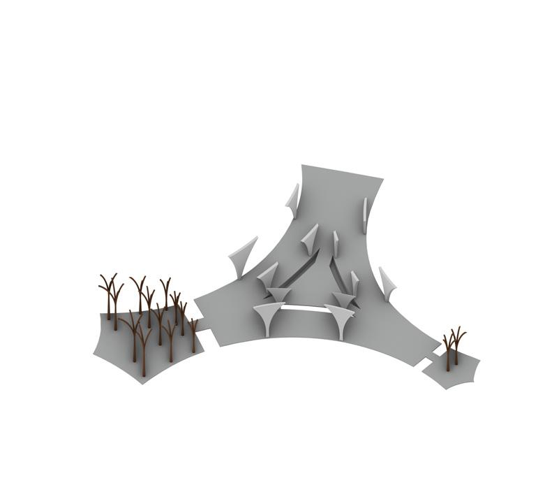
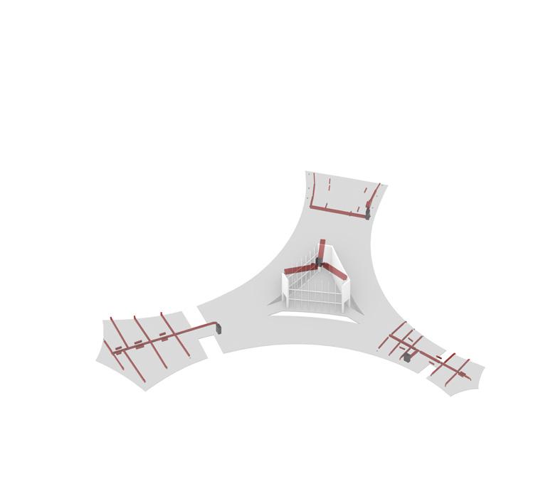
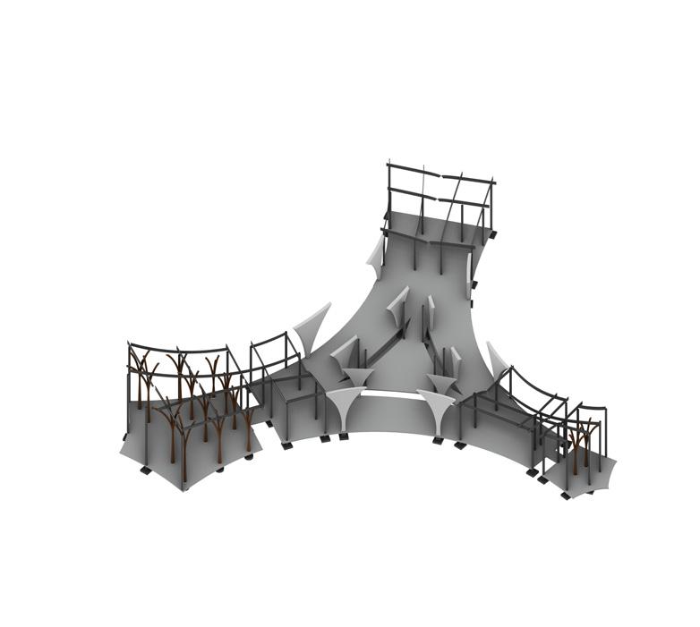
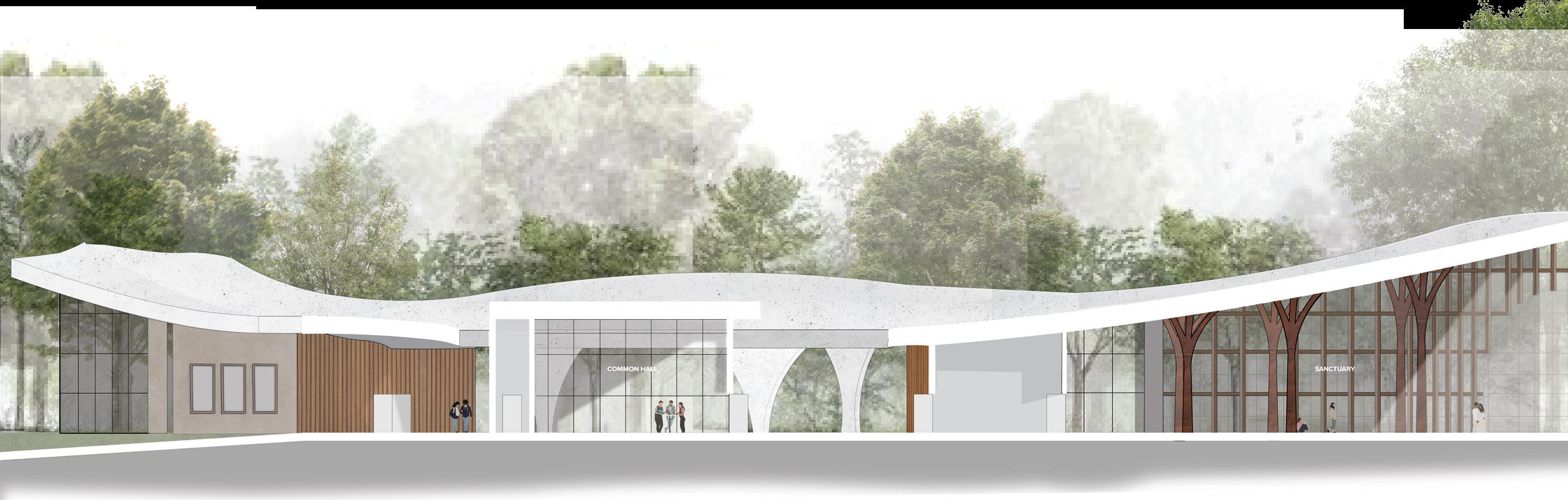
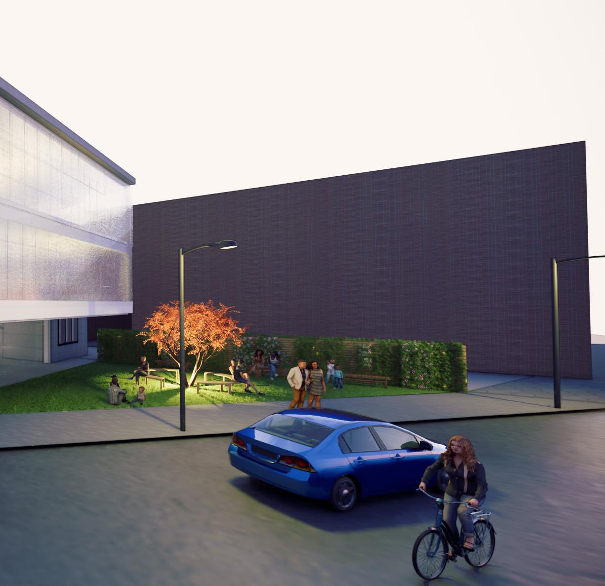
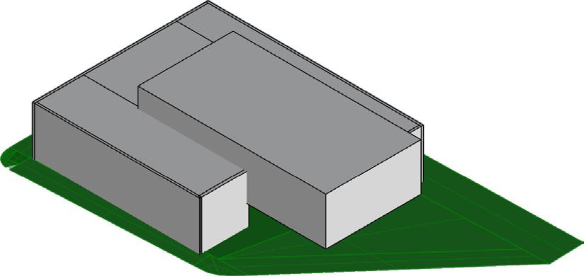
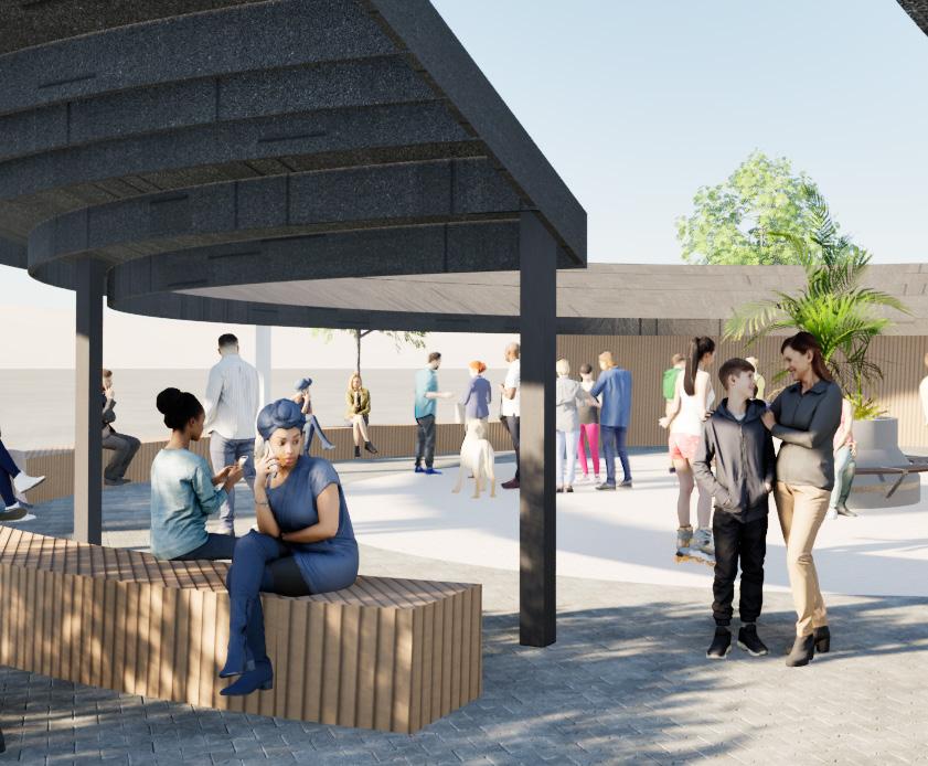
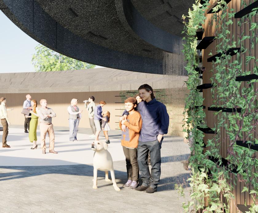
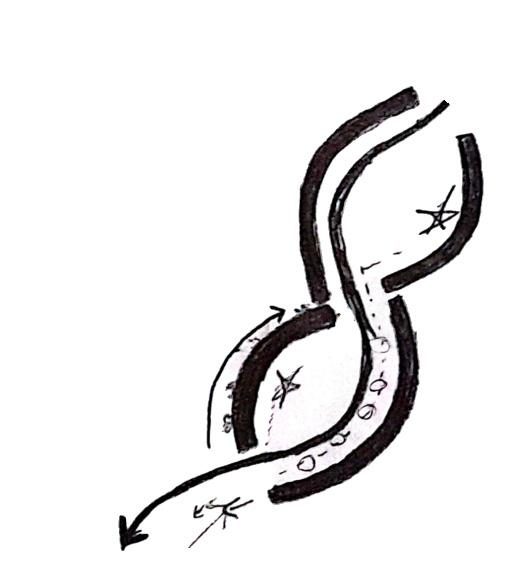
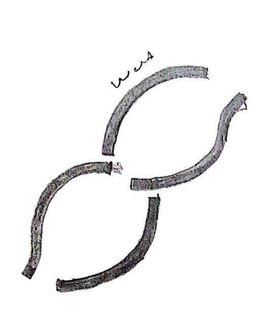
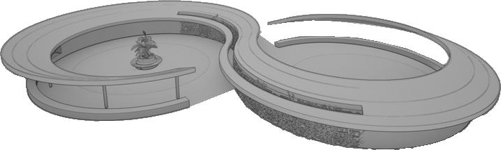
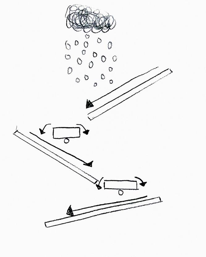
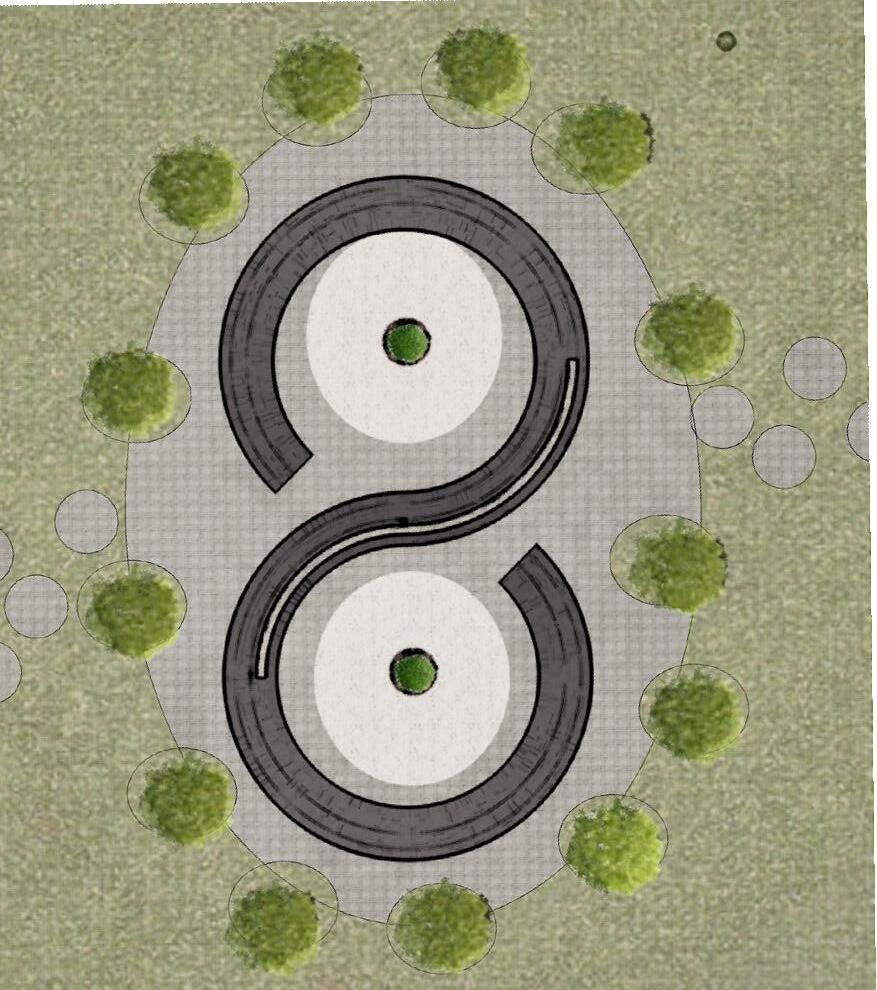
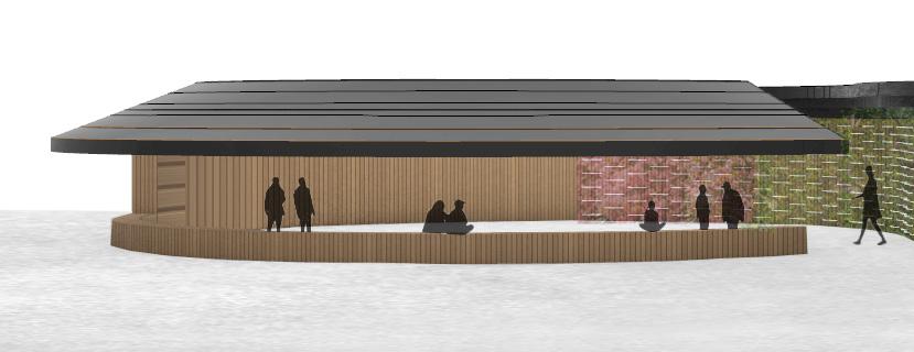
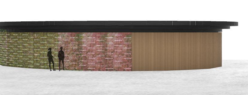
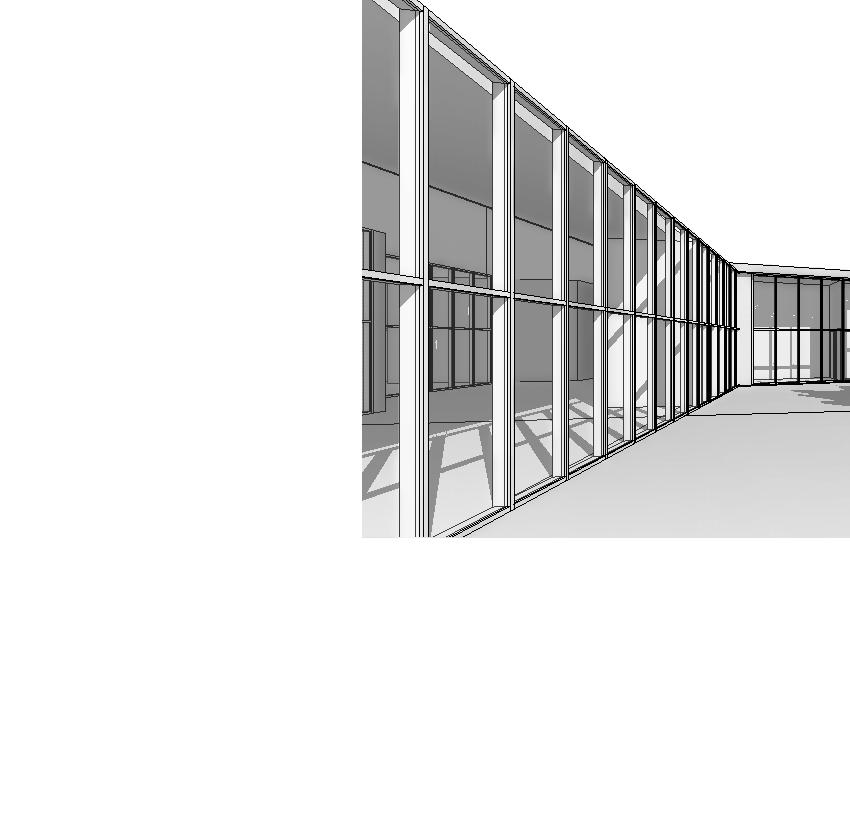
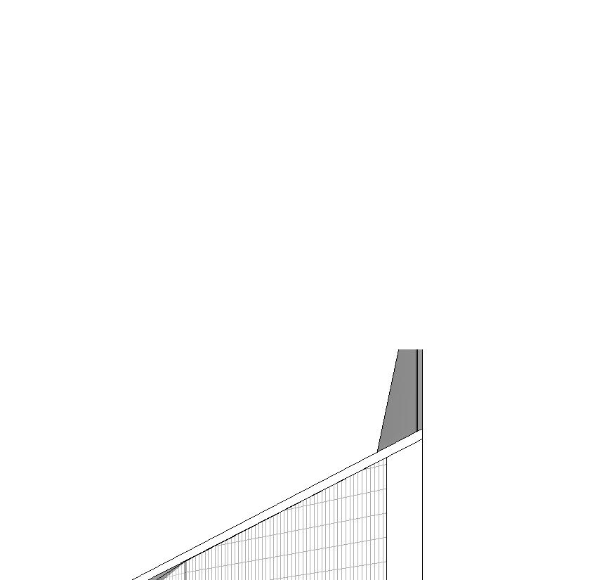
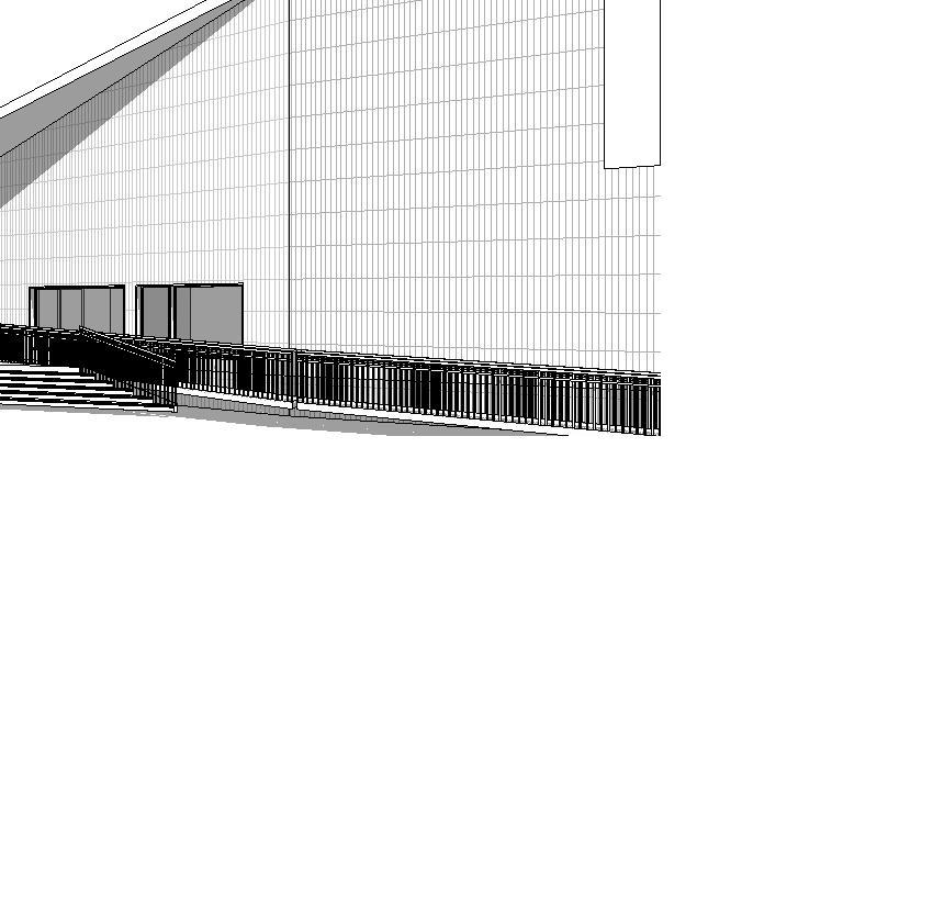
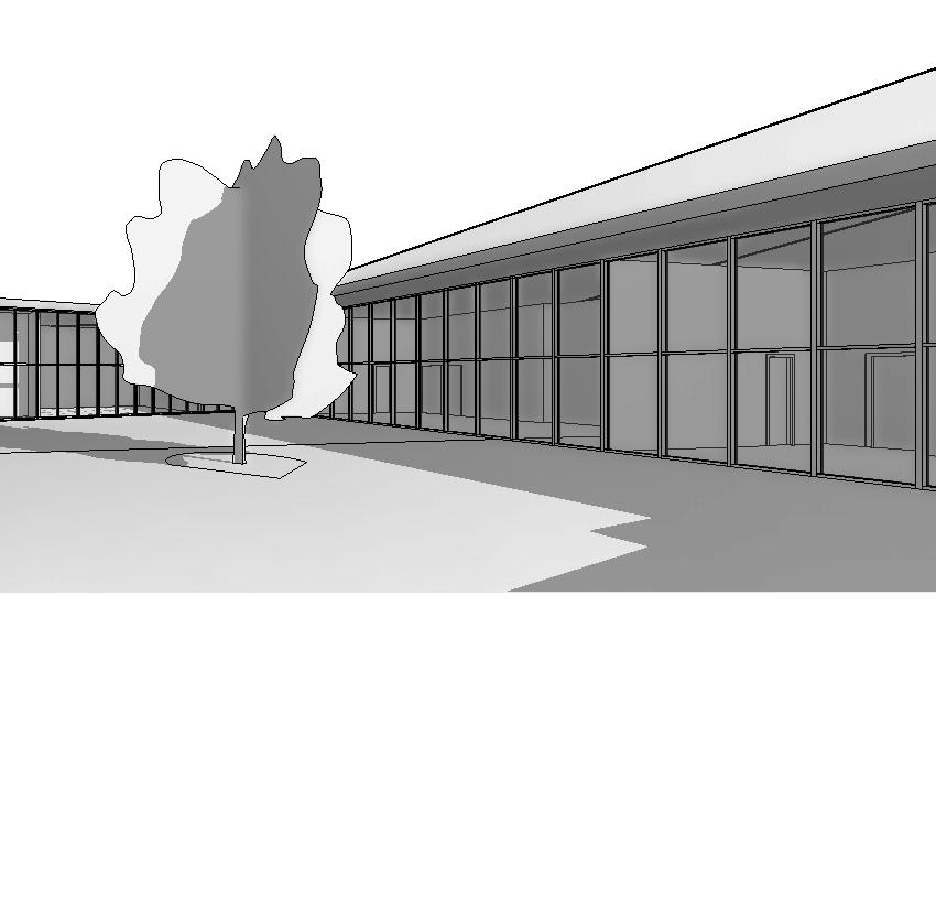
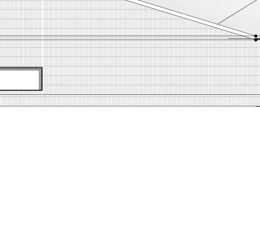
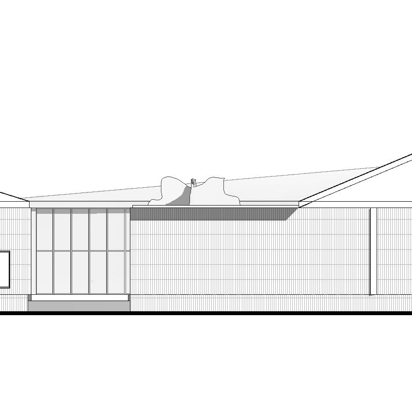
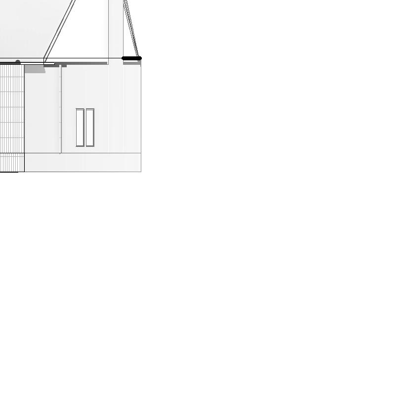
Spiritual Connections
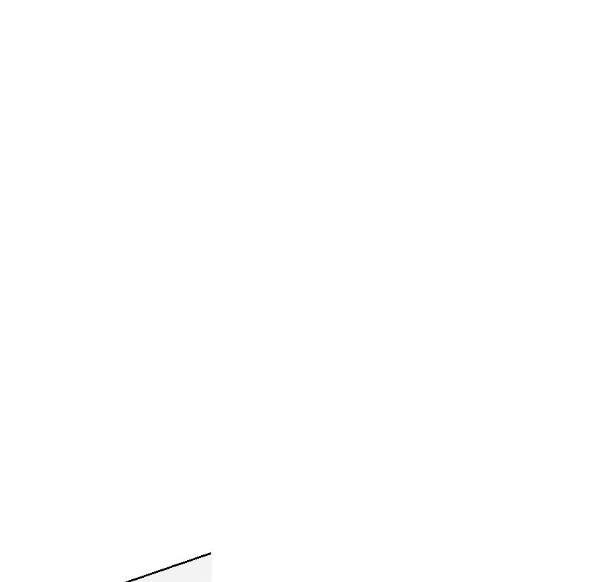
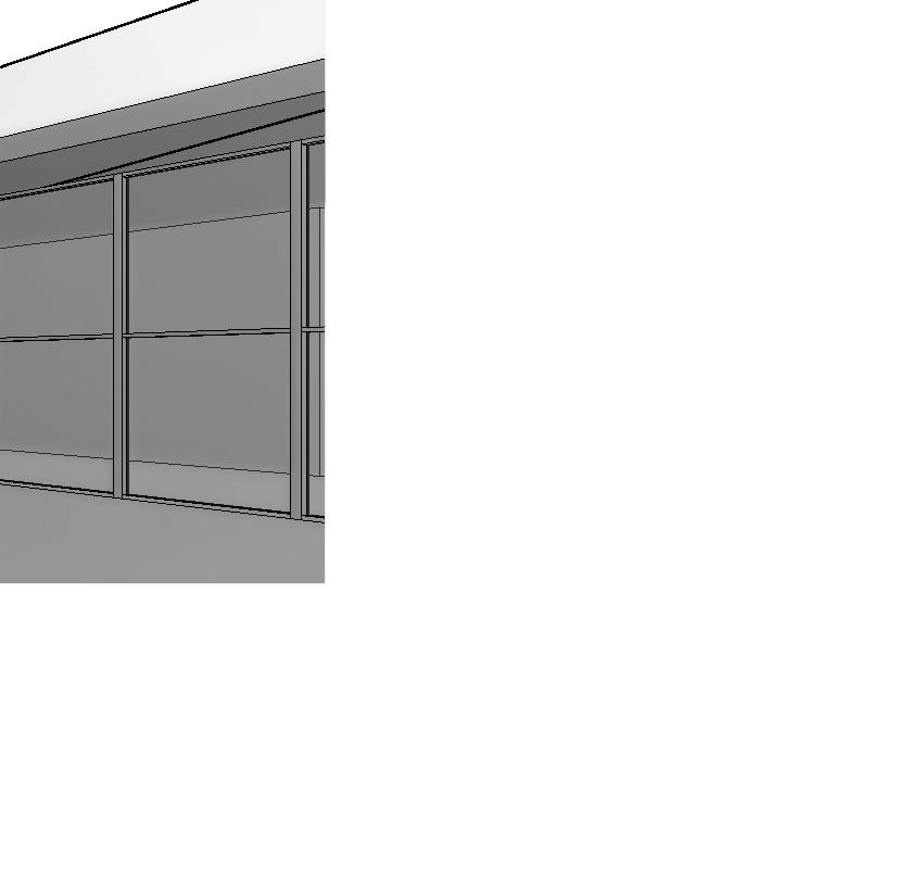
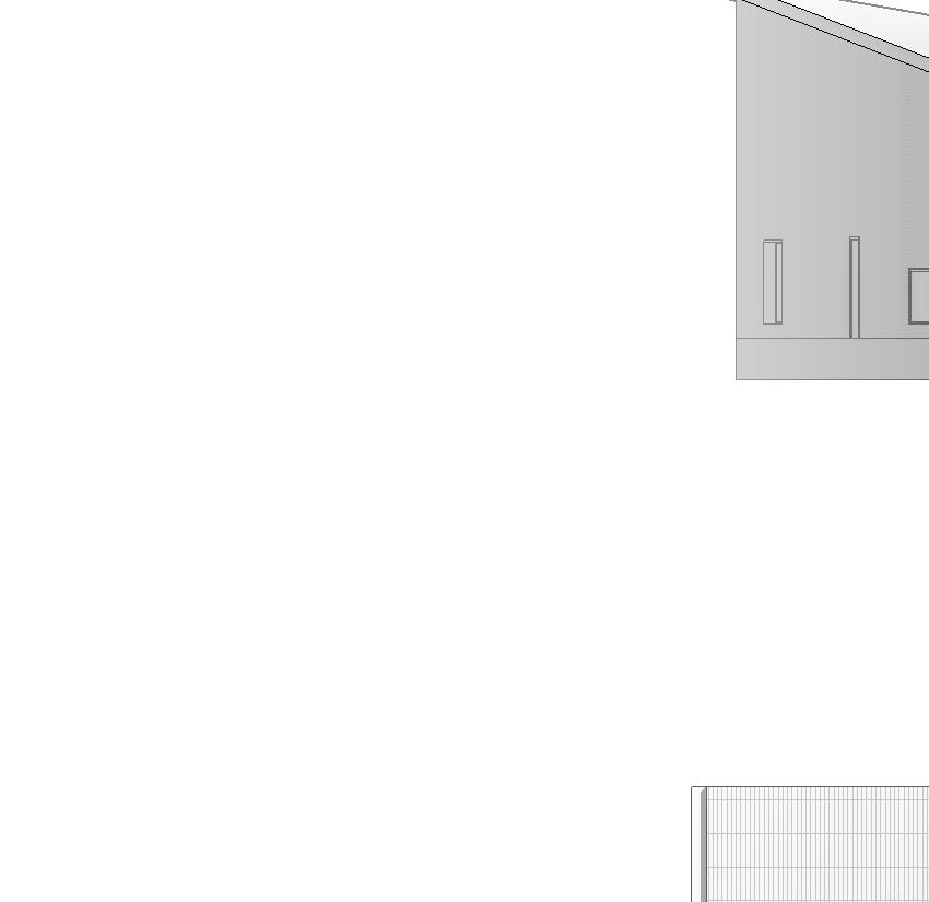
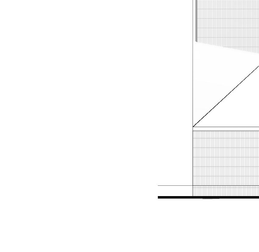
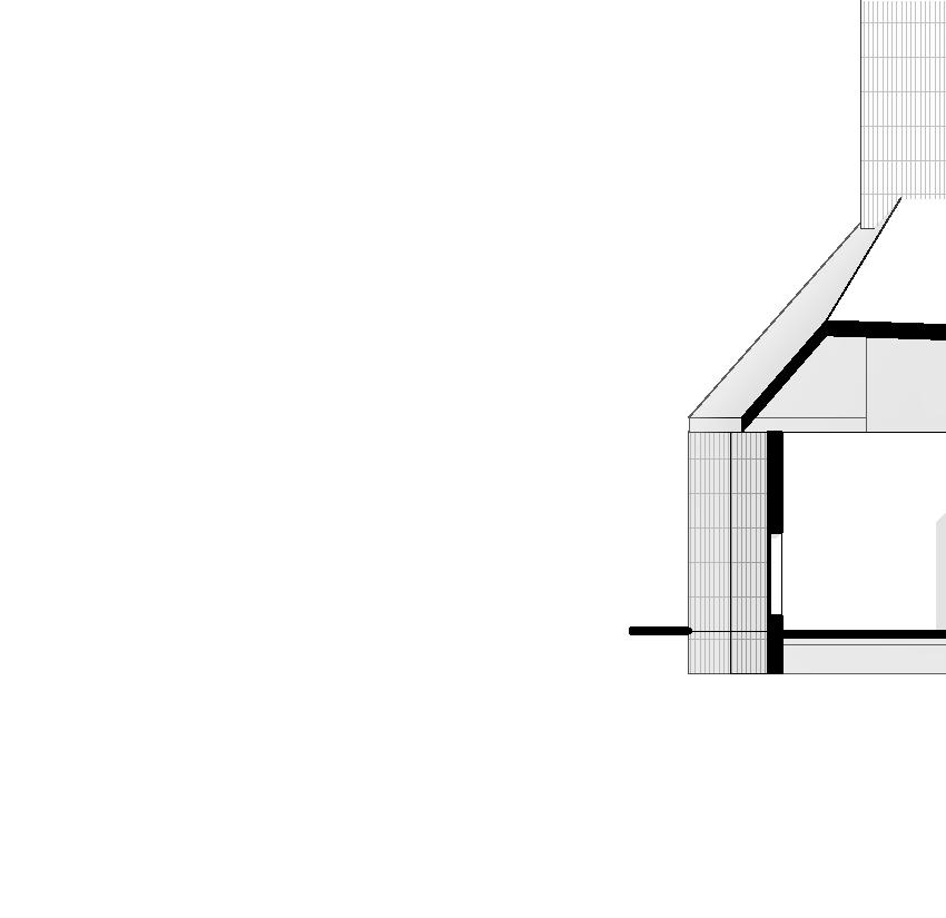
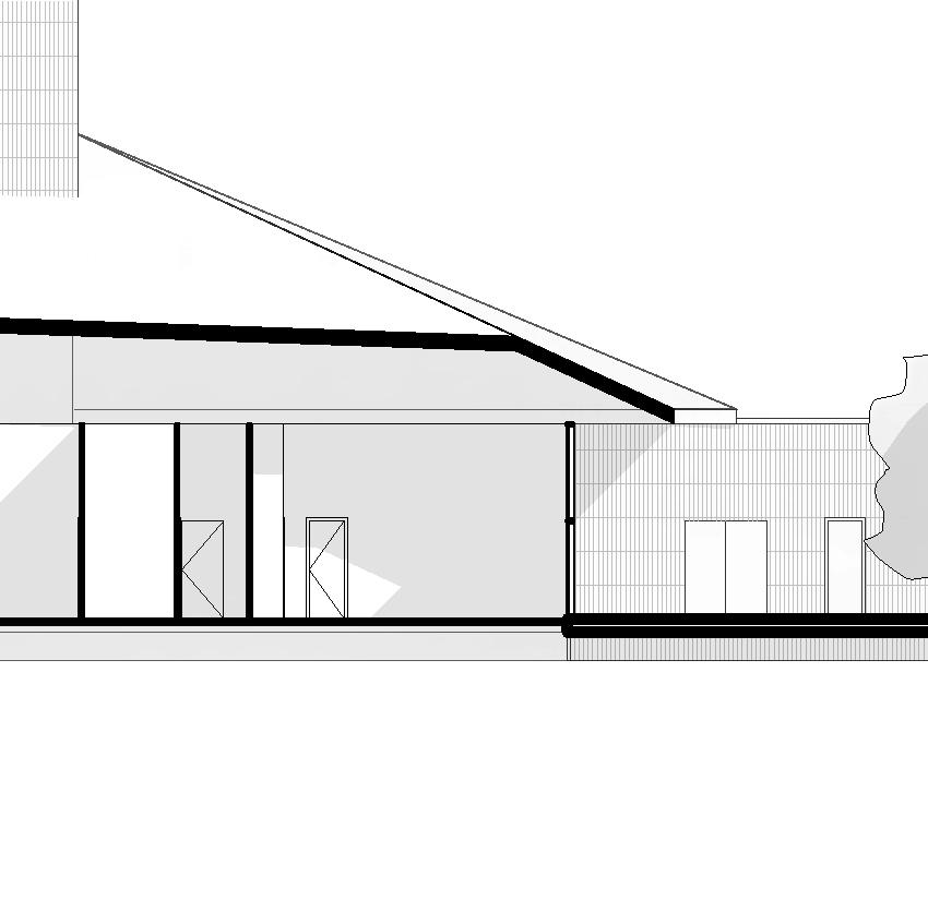
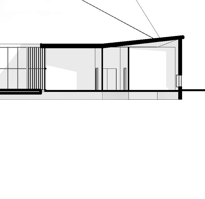
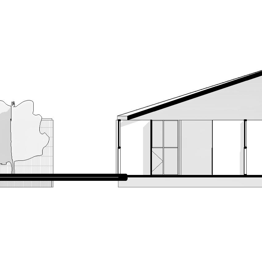
In order to allow occupants to fully embrace spirituality through space, we have created and manipulated forms to be specific to each of the programs that are connected with nature by having a covered walkway between each of them. Different room heights and sizes allow spaces, like the sanctuary, to feel more intimate, while others to be for large gatherings. The roof curves in all directions, not only to allow for sunlight and sunshade, but to allow the occupant to go between each of the spaces.
Designed by Carrie Finfrock, Dean Palahniuk, & Mauricio Vivero, Fall 2024
Image Key:
Floor plan
Site Plan
Walkway Perspective
HVAC Diagram
Indoor vs Outdoor Perspective
Rain Water Roof Circulation
Revit, Illustrator
Photoshop & Illustrator
Rhino & Lumion
Revit
Revit & Illustrator
Revit & Illustrator
West Elevation
South Elevation
Structural Axon
Structural Columns
HVAC Columns and Beams
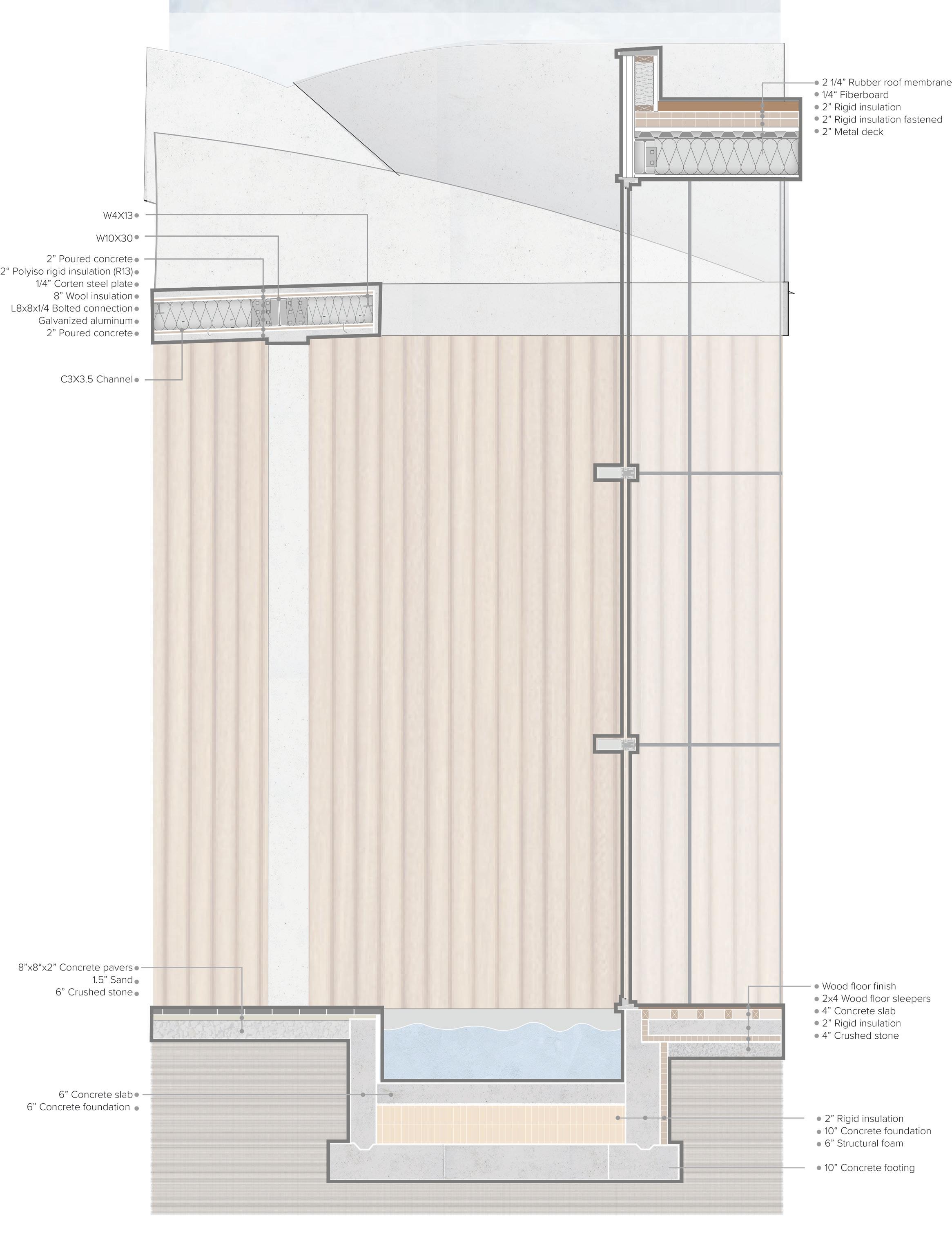
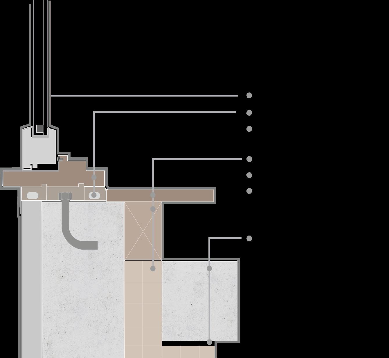
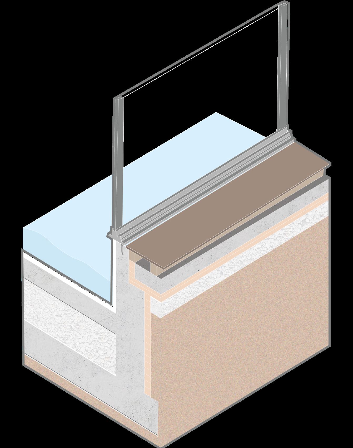
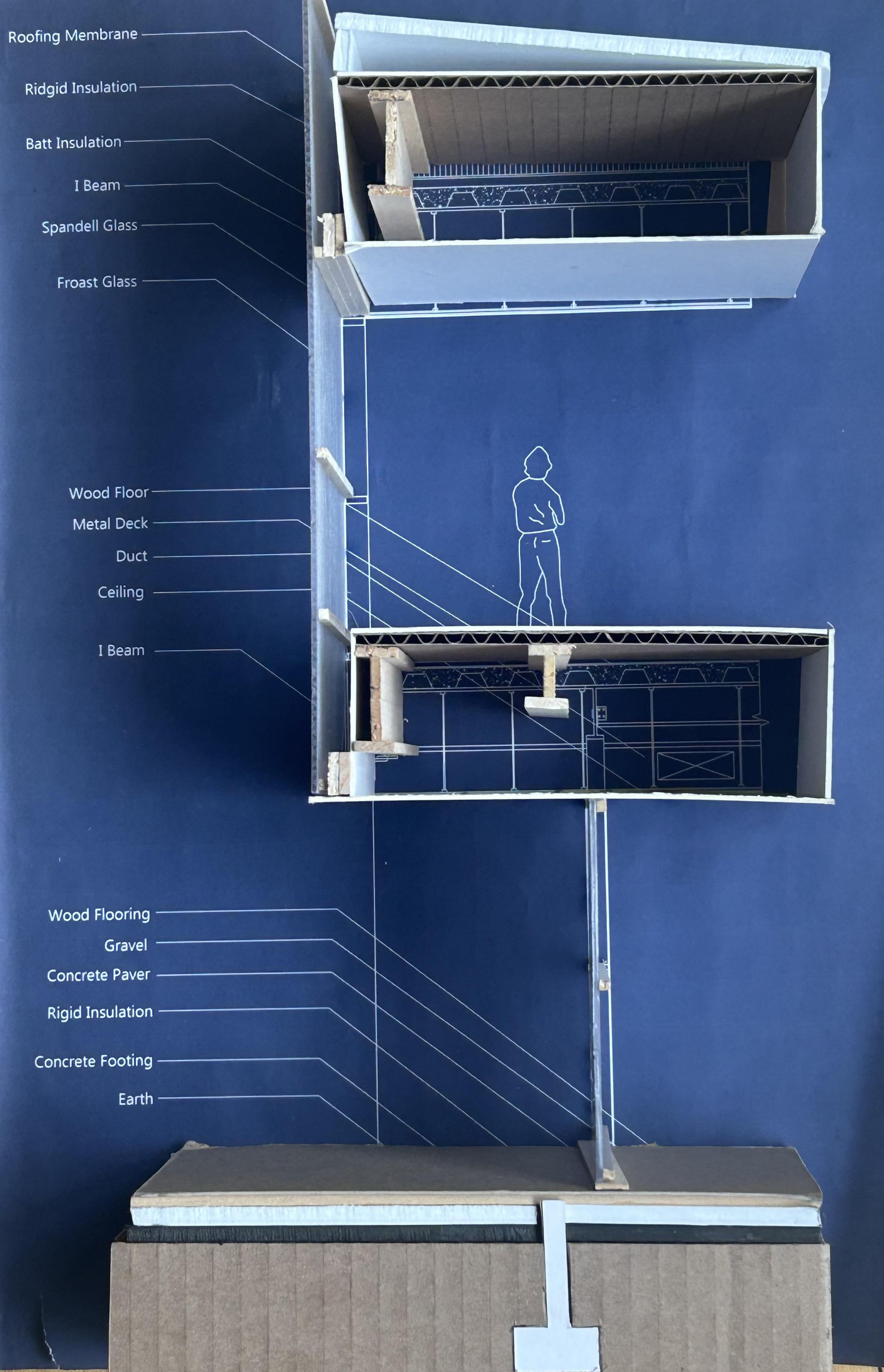
Common Hall Section Detail
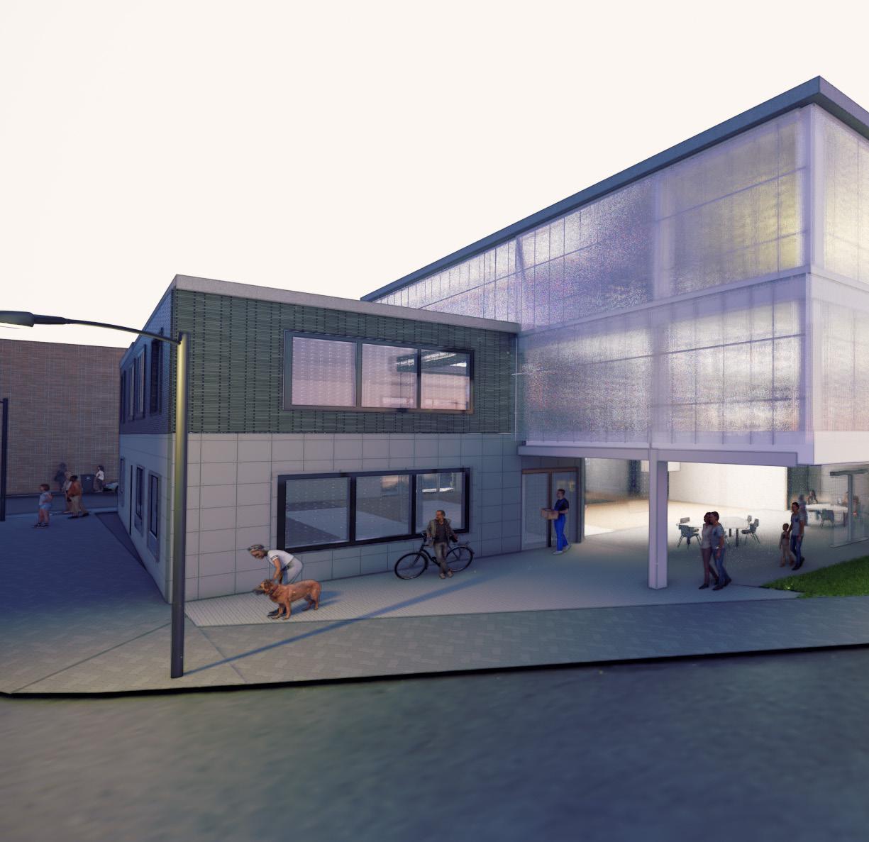
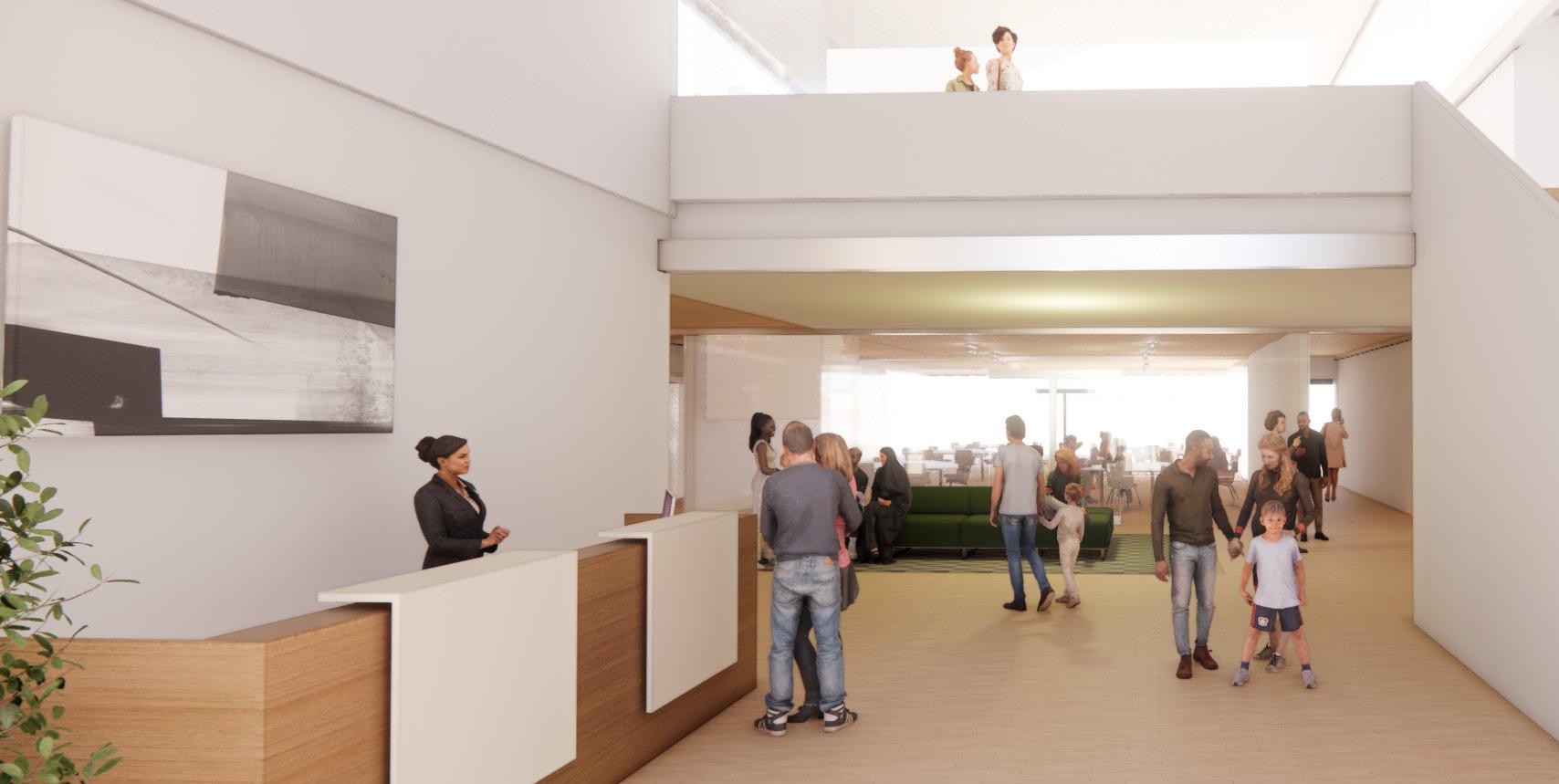
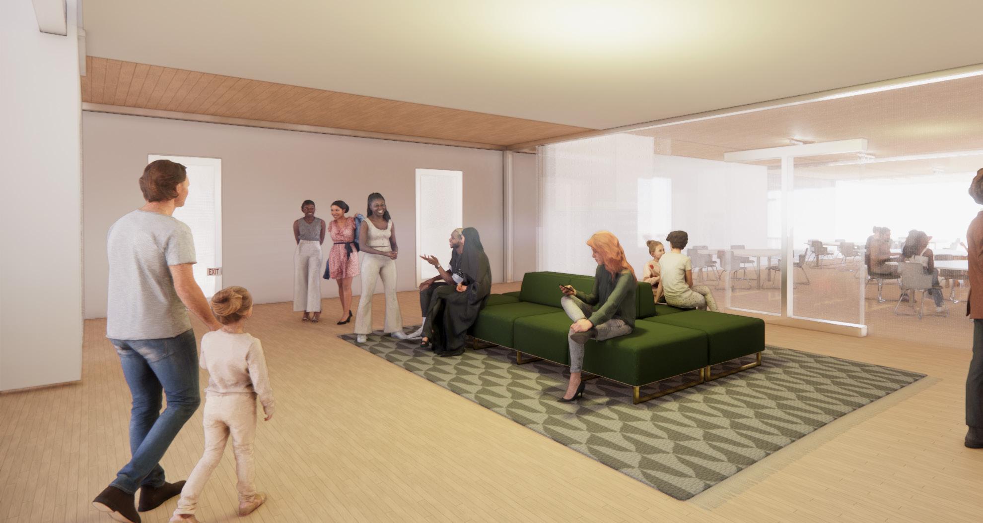
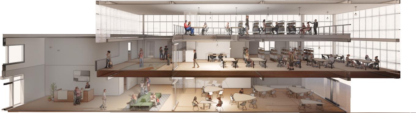
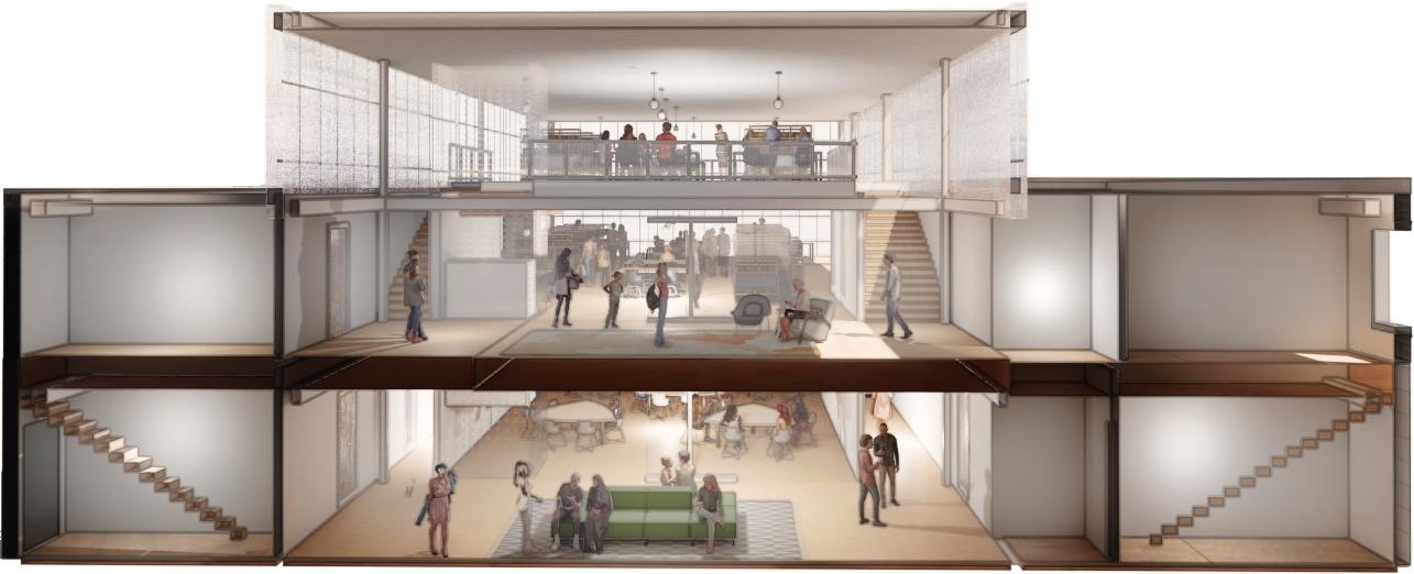
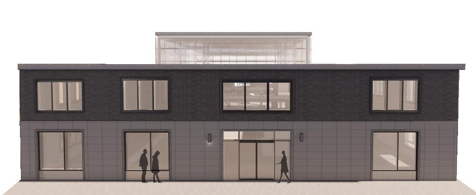
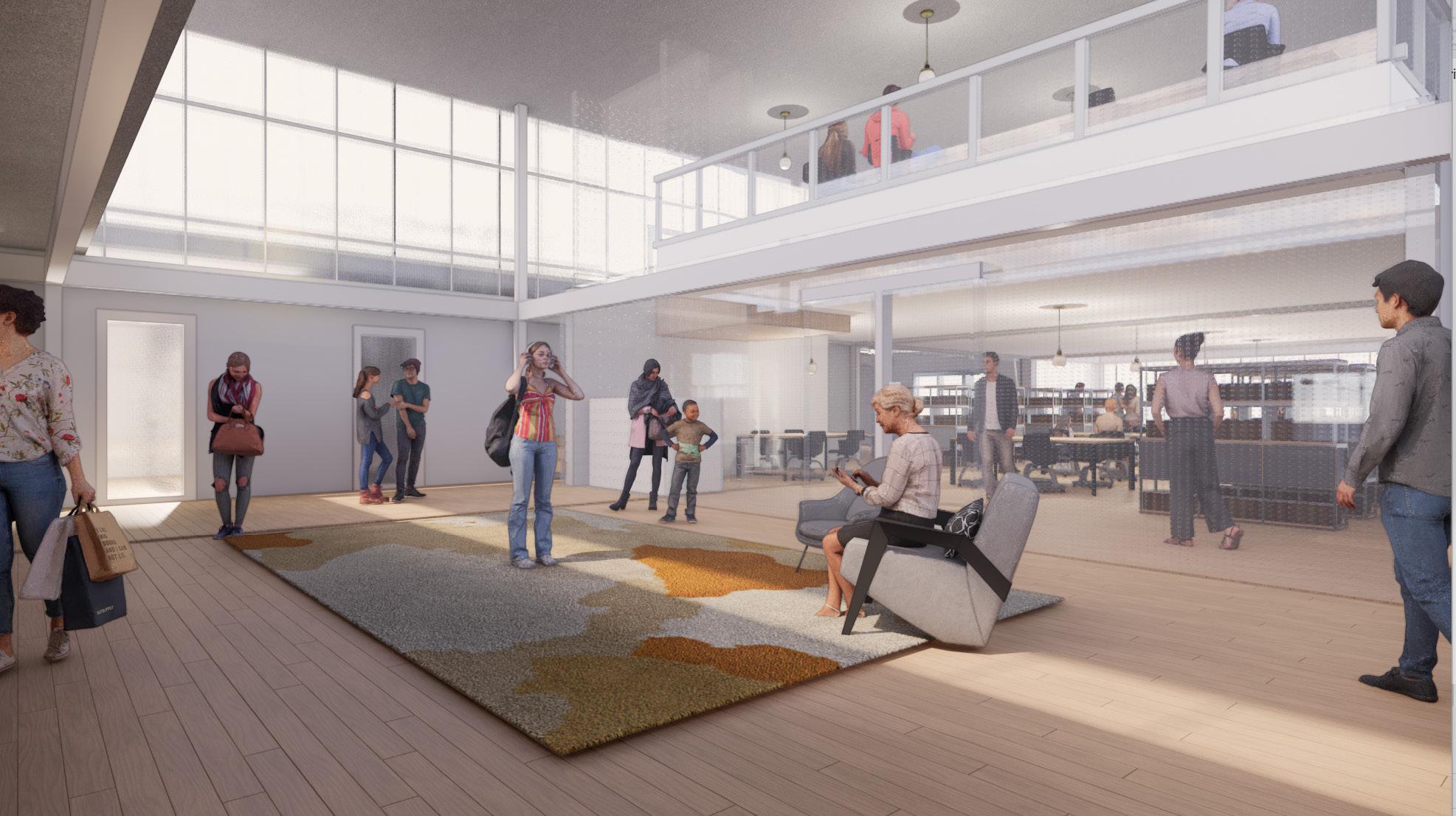
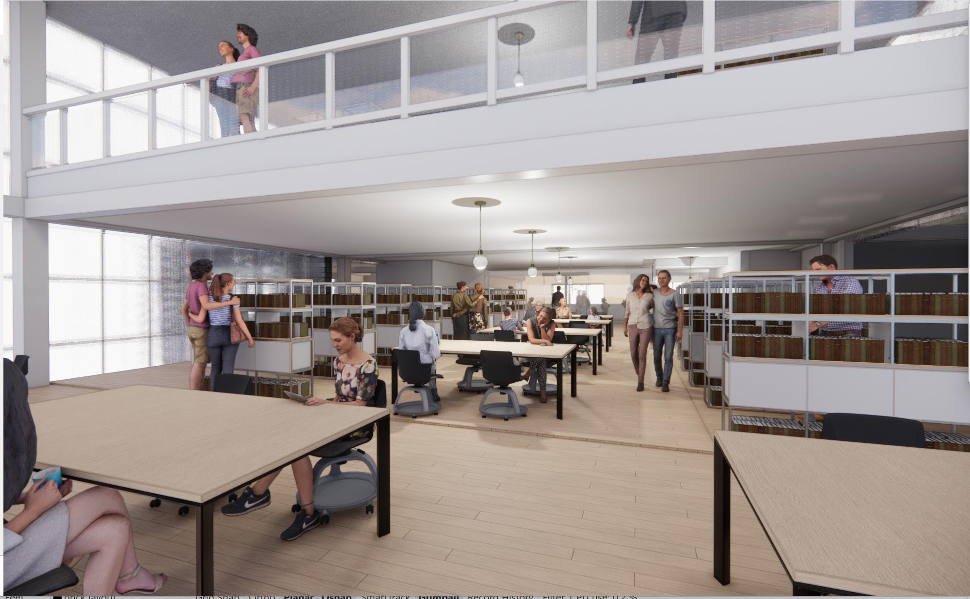
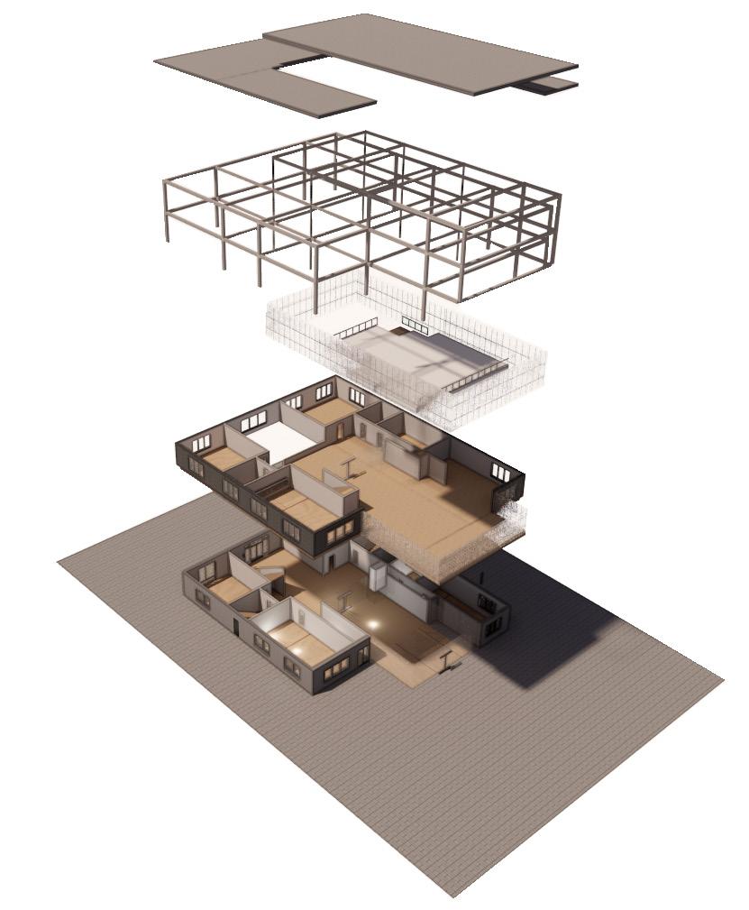
Northern Liberties Multimedia Library
Designed by Carrie Finfrock, Fall 2023
The Northern Liberties Multi-Media library is designed to reflect the rich history of the surrounding neighborhood while providing an open and inviting space for visitors. The ground level of the facade is designed to blend into the surrounding environment while the upper two levels are designed to allow in the warm glow of morning and afternoon sunlight.
Softwares Used: Rhino, Enscape, AutoCAD, and Adobe: Indesign, Photoshop, and Illustrator
Image Key: 01. Lobby perspective
Exhibition space waiting room
Building plans
Softwares Used:
01. Rhino and Enscape 02. Rhino and Enscape
03. AutoCAD
Parti Diagram
Open Stacks Level 2
Open Stacks Level 1
Main Entrance
Exhibition Space
Exhibition Space Lobby
Outside Green Space
Double Height Space
Open Stacks
Exhibition Space Lobby
Fire Stair
Section A
West Elevation
Section B
Facade Material
Grey Brick
Concrete Blocks
Frosted Glass
Gravel
Concrete Footing
Rigid Insulation Concrete Paver Interior Wood Flooring Support For Cladding
Beam
Insulation
Deck with Concrete Slab
Insulation
O3.
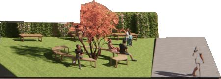
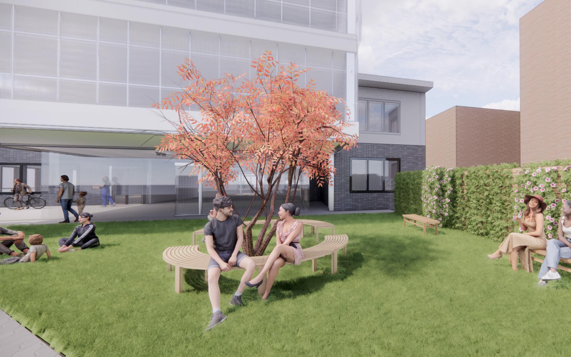
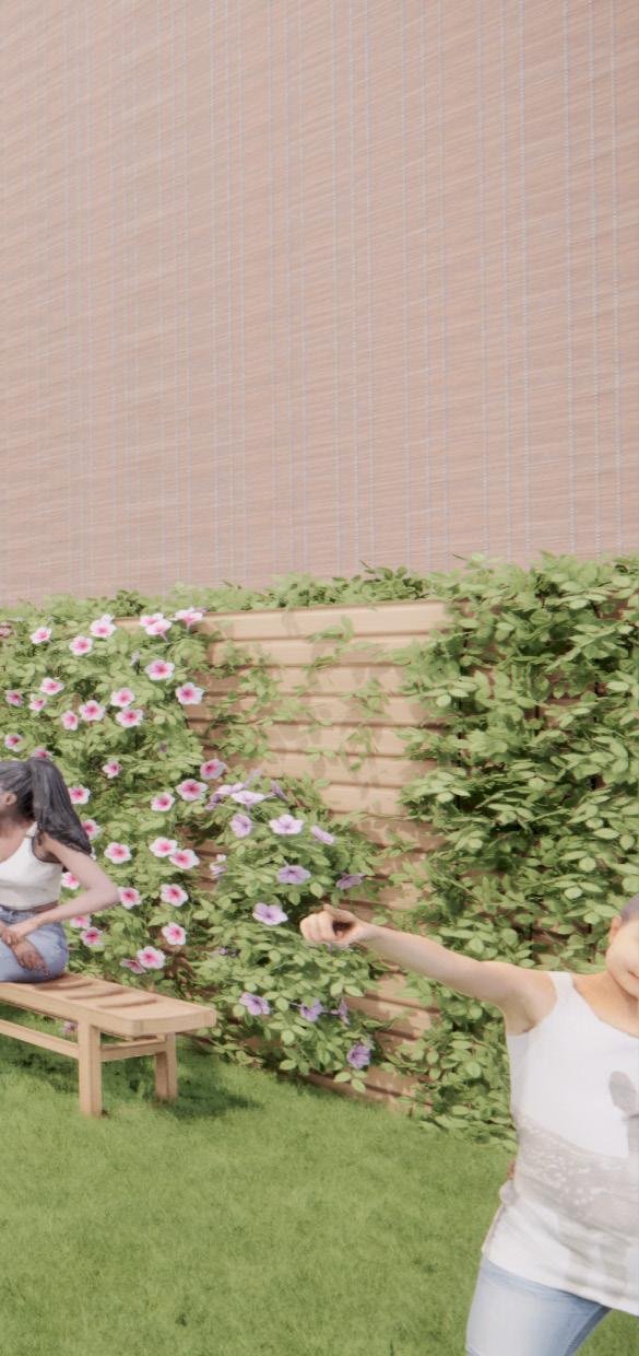
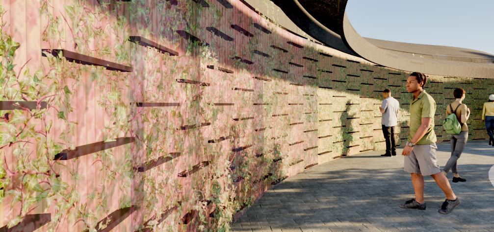
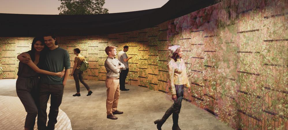
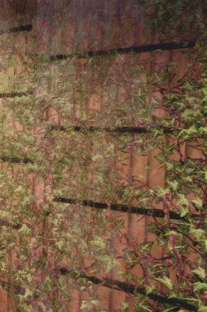
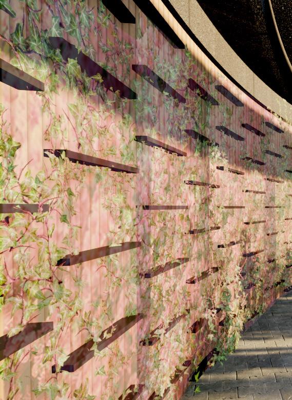
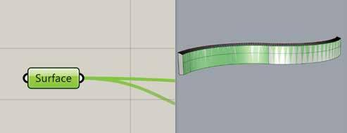
Garden Wall
Designed by Carrie Finfrock & Alex Martz, Spring 2024
The Living Garden Wall was designed to grow plants in an urban environment. The wall’s design allows a variety of plants to be grown that require different exposures of light. The wall utilizes a recirculating drip irrigation system.
Softwares Used: Rhino, Grasshopper, Twin Motion, and Adobe: Indesign, Photoshop, and Illustrator
Image Key:
01. Garden Wall at daytime
02. Garden Wall at nigh time
Softwares Used:
01. Rhino and Twin Motion
02. Rhino and Twin Motion
Bench
Circulation Courtyard
Vertical Garden
Mirror Half’s
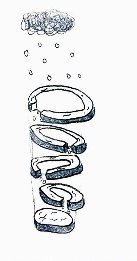
Final Form with Program
Original Concept Diagram
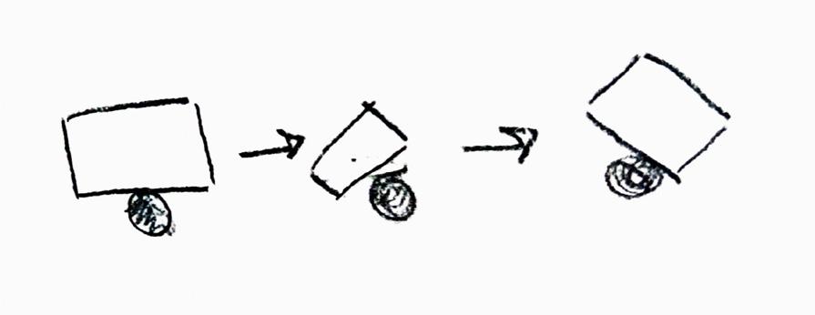
Water falling down (input)
More Sound Less Sound
Rotating mechanism (Process)
Plate moves left of right depending on water placement (Output)
Preliminary Sketches
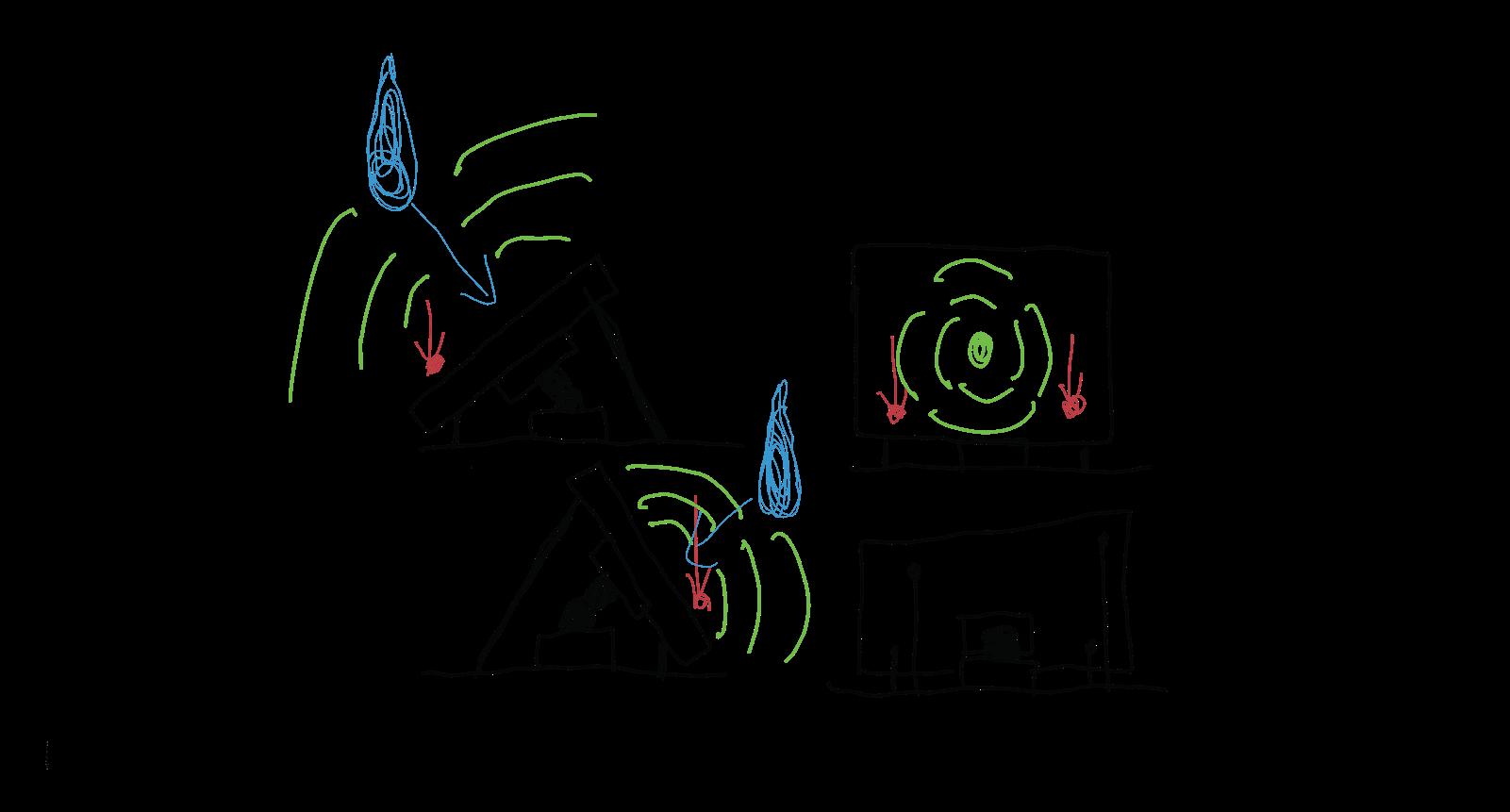
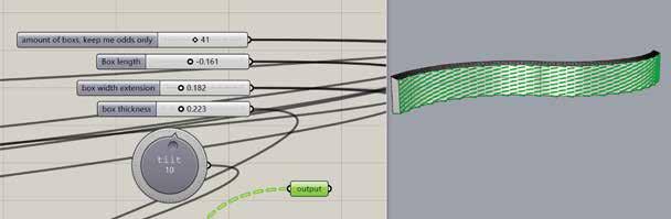
Tilting box
Exterior Pathway
Pathway
Installation Plants
Pansies:
Love well-drained and fertile soil, direct morning sun, and afternoon shade. They grow well in spring and fall.
Strawberries:
Take well to vertical growing conditions and enjoy direct sunlight and rich, well draining soil
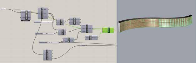
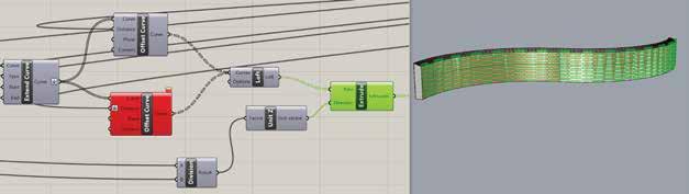
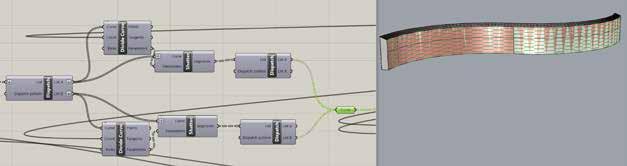
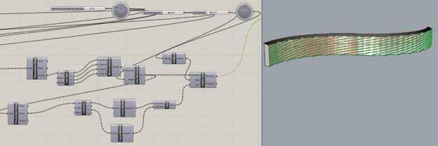
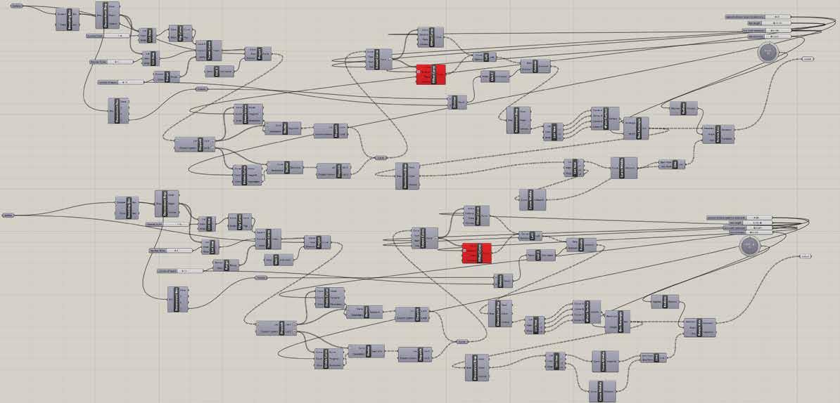
Steps of the Grasshopper Script
Whole Grasshopper Script
The Garden Wall was designed using the Grasshopper script to create the form of the structure as well as the rotating plates.
O6.
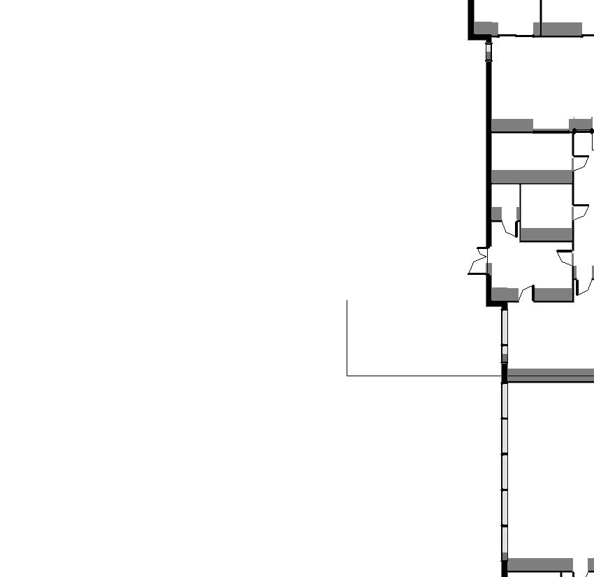
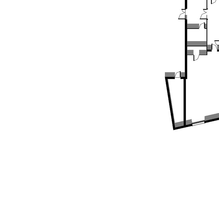
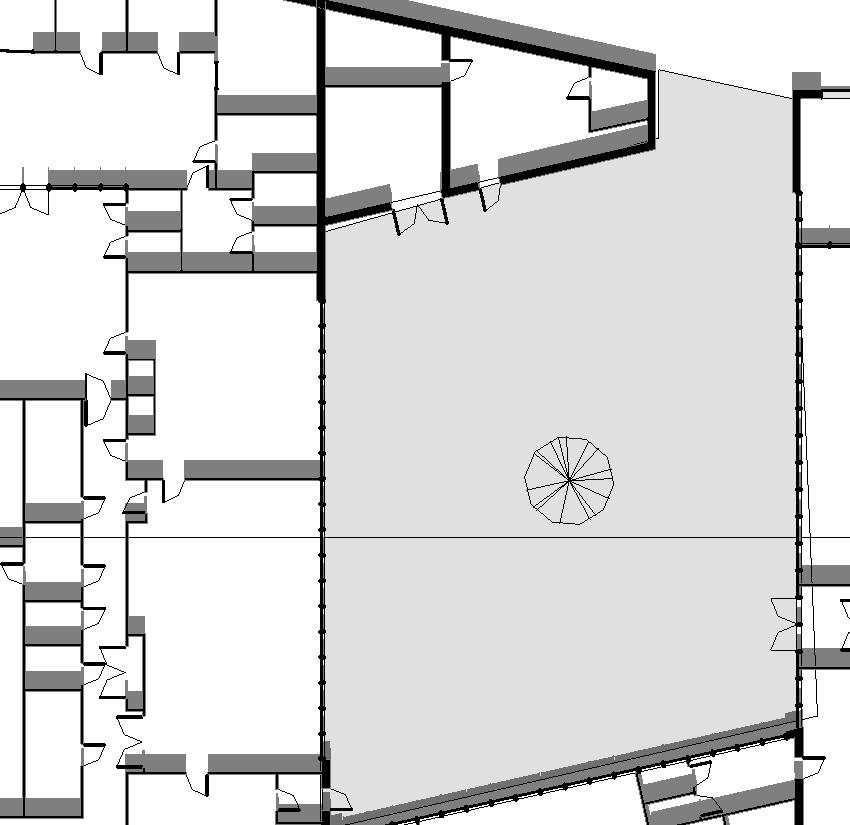
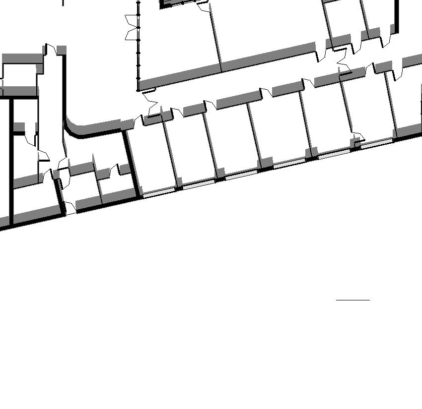
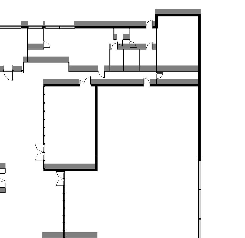
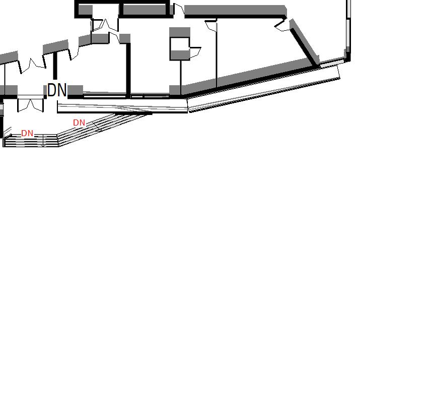
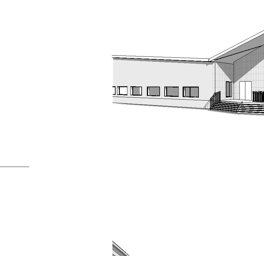
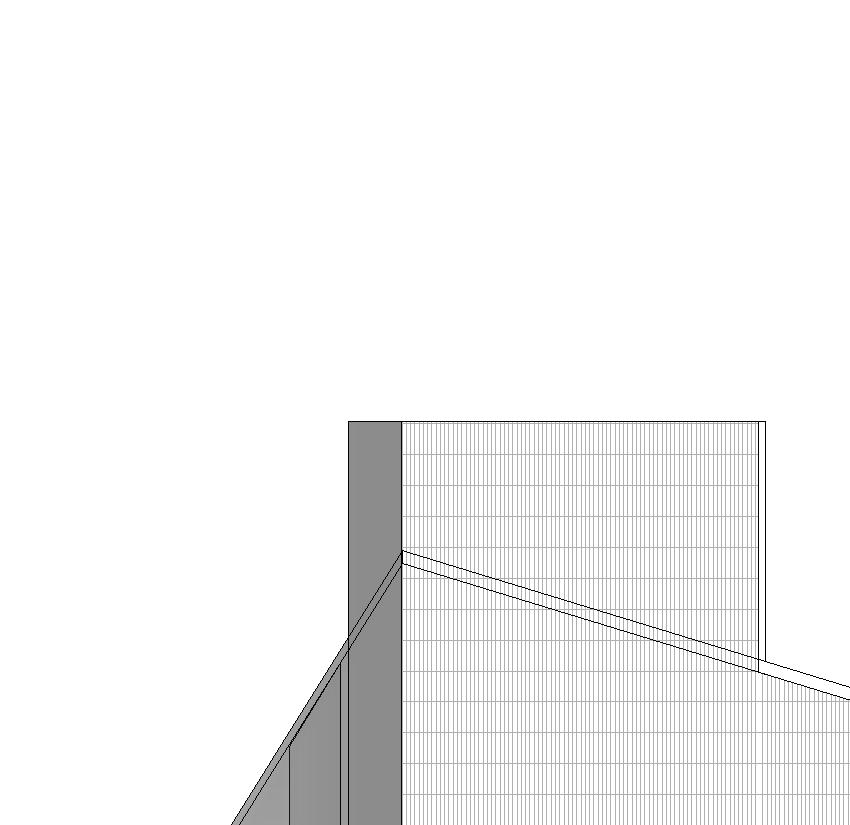
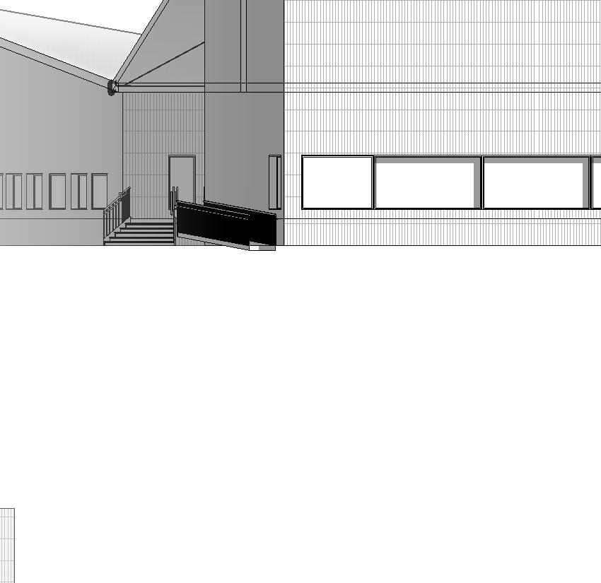
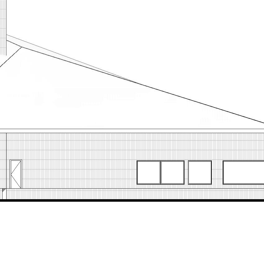
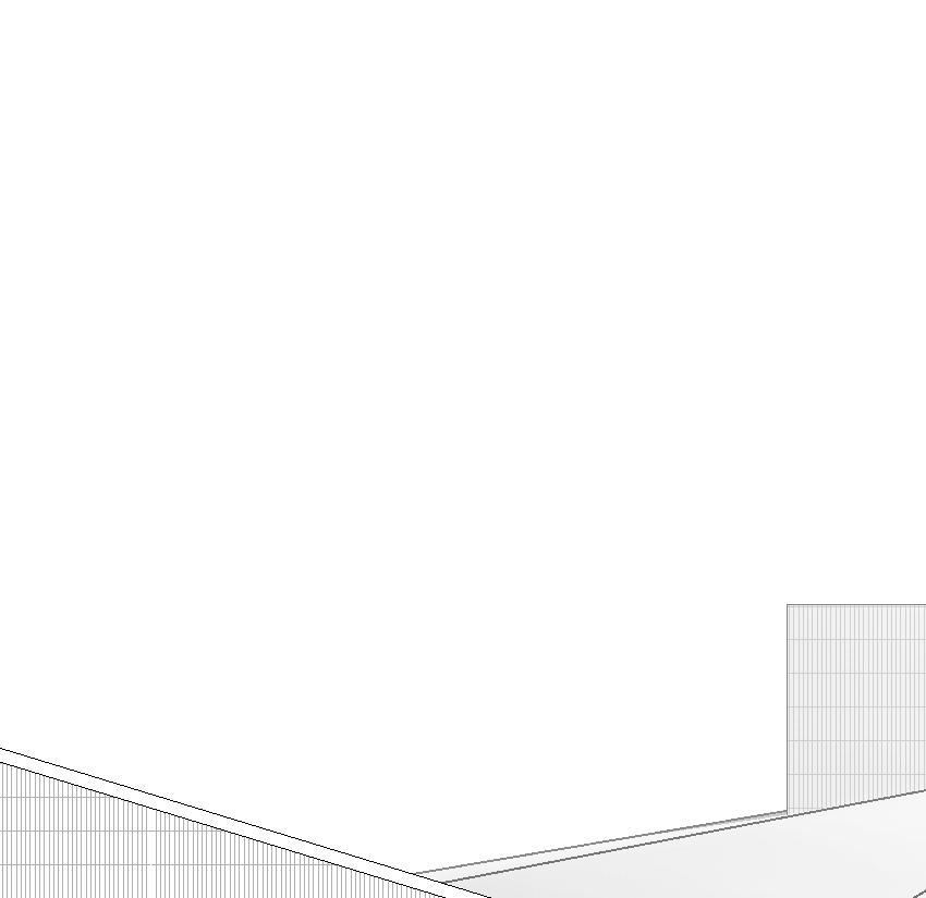
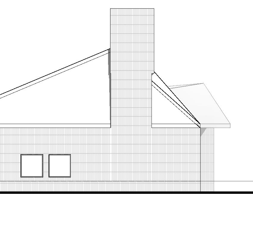
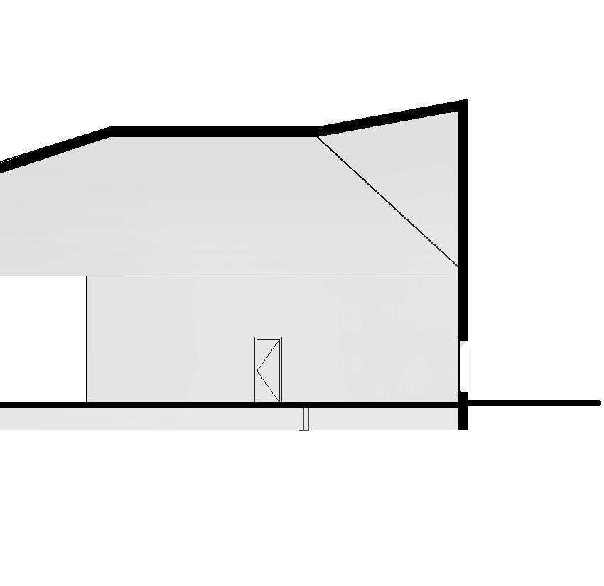
Suvela Chapel Modeling Activity
The Suvela Chapel is a recreation of the chapel utilizing the Revit software. The design also includes a life safety plan, room occupancy, and fire rated wall and floor systems.
Draw by Carrie Finfrock, Mauricio Vivero & Dean Palahniuk, Fall 2024
Designed by: OOPEAA
Softwares Used: Revit
September 17th,
DATE: SHEET NAME: DRAWN BY 3/64" = 1'-0"
Section 1 Style A 1
3/64" = 1'-0" A150
Section 2 Style A 2
3/64" = 1'-0" A150
5 45'-3"
September 17th, 2024
DATE: SHEET NAME: DRAWN BY 3/64" = 1'-0"
UL DESIGN NO L570
3/4" ENGINEERED HARDWOOD
0.030" VAPOR BARRIER
1" FINISH FLOOR
ASSEMBLY OPTIONS:
1. Flooring System The flooring system shall consist of one of the following: 1. Subflooring — Nom 19/32 in. thick wood structural panels installed perpendicular to the joists with end joints staggered. Plywood or panels secured to joists with construction adhesive and No. 6d ringed shank nails, spaced 12 in. OC along each joist. Staples having equal or greater withdrawal and lateral resistance strength may be substituted for the 6d nails.
2. Vapor Barrier Nom 0.030 in. thick commercial asphalt saturated felt. 3. Finish Floor Min 1 by 4 in. T & G lumber installed perpendicular to the joists thick wood structural panels, min grade "Underlayment" or "Single-Floor". Face grain of plywood or strength axis of panel to be perpendicular to joists with joints staggered.
2. Structural Wood Members* Min 9-1/2 in. deep "I" shaped wood joists spaced at a max of 19.2 in. OC. Joists shall conform to ICC-ES ESR-1153 Report. Joist top and bottom chords minimum 1-3/8 in. deep by 2.3 in. wide and constructed of either Microllam laminated veneer lumber (LVL) or TimberStrand laminated strand lumber (LSL). Webs constructed of minimum 3/8 in. thick Performance Plus OSB, PS2, Exposure 1. Installation shall be in accordance with manufacturers published literature. Spacing may be increased to 24 in. OC when Batts and Blankets* (Item 3B) is used.
3. Insulation —Glass fiber insulation, secured to the subflooring with staples, or to the wood joists with 0.090 in. diam galv steel wires, or draped over the resilient channel/gypsum panel (or Steel Framing Members/gypsum panel) ceiling membrane. Any thickness of glass fiber insulation bearing the UL Classification Marking as to Surface Burning Characteristics and/or Fire Resistance.
4. Resilient Channels Formed from 25 MSG galv steel installed perpendicular to the joists. When no insulation is installed in the concealed space the resilient channels are spaced 24 in. OC. When insulation (Item 3) is installed to the underside of the subfloor the resilient channels are spaced . 16 in. OC When insulation (Items 3, 3A or 3B) is applied over the resilient channel/gypsum panel ceiling membrane, the resilient channels are spaced 12 in. OC.. Two courses of resilient channel positioned 6 in. OC at gypsum panel butt-joints (3 in. from each end of wallboard). Channels oriented opposite at gypsum panel butt-joints. Channel splices overlapped 4 in. beneath wood trusses. Channels secured to each truss with 1-1/4 in. long Type S screws.
"I" SHAPED WOOD JOISTS
GLASS FIBER INSULATION
1/8" RESILIENT CHANNELS
5/8" GYPSUM BOARD
5/8" GYPSUM BOARD
5. Gypsum Board* — Two layers of 5/8 in. thick by 4 ft wide gypsum panels, installed perpendicular to resilient channels (Item 4). The base layer of panels screw-attached to the resilient channels with 1 in. long Type S screws spaced 8 in. OC at the butt joints and 16 in. OC in the field of the panel. The face layer screwattached to the resilient channels with 1-5/8 in. Type S screws spaced 8 in. OC and 1-1/2 in. Type G screws spaced 8 in. OC at the butt joints located mid-span between resilient channels.
UL DESIGN NO U319
ASSEMBLY OPTIONS:
1. Gypsum Board Two layers of 5/8" thick gypsum wallboard with beveled, square or tapered edges, nailed 7 in. OC with 4d cement coated nails minimum 1-3/8 in. long, 0.080 in. shank diam and 7/32 in. diam heads. If wallboard is other than 48 in. wide, application must be horizontal. Finish Rating 8 min.
2. Joints Exposed joints covered with joint compound and paper tape. Joint compound and paper tape may be omitted when square edge boards are used.
3. 2x4's Fire Stopped
4. Nailheads — Exposed or covered with joint compound.
UL DESIGN W496
ASSEMBLY OPTIONS:
1. Floor and Ceiling Runners (Not Shown) Channel shaped, fabricated from min 0.0329 in., bare metal thickness (No. 20 MSG) corrosion-protected steel, that provide a sound structural connection between steel studs and adjacent assemblies such as floors, ceilings and/or other walls. Attached to floor and ceiling assemblies with steel fasteners spaced not greater than 24 in. OC.
2. Gypsum Board Gypsum panels with beveled, square or tapered edges, applied vertically or horizontally. Vertical joints centered over studs and staggered one stud cavity on opposite sides of studs. Vertical joints in adjacent layers (multilayer systems) staggered one stud cavity. Horizontal joints need not be backed by steel framing. Horizontal edge joints and horizontal butt joints on opposite sides of studs need not be staggered when load is reduced to 90 percent of max stud capacity. When load is at 100 percent, horizontal edge joints and horizontal butt joints on opposite sides of studs staggered a min of 12 in. Horizontal edge joints and horizontal butt joints on opposite sides of studs need not be staggered at 100 percent load with Type ULIX. Horizontal edge joints and horizontal butt joints in adjacent layers (multilayer systems) staggered a min of 12 in. Horizontal edge joints and horizontal butt joints in adjacent layers (multilayer systems) with Type ULIX need not be staggered. When used in widths other than 48 in., gypsum panels to be installed horizontally.
3. Steel Studs Channel shaped, fabricated from min 20 MSG corrosion-protected or galv steel, 3-1/2 in. min width, min 1-1/2 in. flanges and 1/4 in. return, spaced a max of 16 in. OC. Studs friction-fit into floor and ceiling runners.
4. Insulation 3 1/2 " Glass fiber insulation
5. Lateral Support Members (Not shown) Where required for lateral support of studs, support shall be provided by means of steel straps, channels or other similar means as specified in the design of a particular steel stud wall system.
6. Gypsum Board Gypsum panels with beveled, square or tapered edges, applied vertically or horizontally. Vertical joints centered over studs and staggered one stud cavity on opposite sides of studs. Vertical joints in adjacent layers (multilayer systems) staggered one stud cavity. Horizontal joints need not be backed by steel framing. Horizontal edge joints and horizontal butt joints on opposite sides of studs need not be staggered when load is reduced to 90 percent of max stud capacity. When load is at 100 percent, horizontal edge joints and horizontal butt joints on opposite sides of studs staggered a min of 12 in. Horizontal edge joints and horizontal butt joints on opposite sides of studs need not be staggered at 100 percent load with Type ULIX. Horizontal edge joints and horizontal butt joints in adjacent layers (multilayer systems) staggered a min of 12 in.
Horizontal edge joints and horizontal butt joints in adjacent layers (multilayer systems) with Type ULIX need not be staggered. When used in widths other than 48 in., gypsum panels to be installed horizontally.