philipe3

Page 1

CHAPTER 18

El

Direct Filling Gold

551

Although compacted golds develop increased hardness nnci sti-eng~hby cold wor-kingduring compacting, a furthe1 increase in hardness can be achieved through the addition of other elements, such as pall,ldiurn, platinum, indiuru, and silver, without affecting the handling properties.

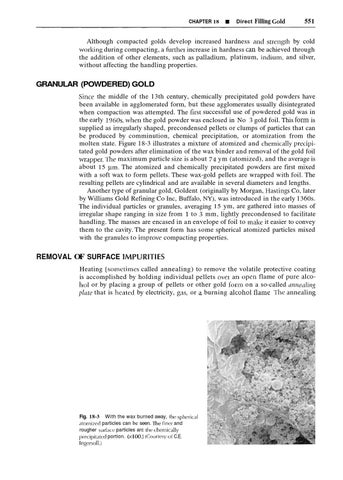
GRANULAR (POWDERED) GOLD Since the middle of the 13th century, chemically precipitated gold powders have been available in agglomerated form, but these agglomerates usually disintegrated t use of powdered gold was in when compaction was attempted. The f i ~ ssuccessful the early 1360s, when the gold powder was enclosed in No 3 gold foil. This form is supplied as irregularly shaped, precondensed pellets or clumps of particles that can be produced by comminution, chemical precipitation, or atomization from the molten state. Figure 18-3 illustrates a mixture of atomized and chernically pretipitated gold powders after elimination of the wax binder and removal of the gold foil wrapper. 'l'he maximum particle size is about 74 ym (atomized), and the average is about 15 ym. The atomized and chemically precipitated powders are first mixed with a soft wax to form pellets. These wax-gold pellets are wrapped with foil. The resulting pellets are cylindrical and are available in several diameters and lengths. Another type of granular gold, Goldent (originally by Morgan, Hastings Co, later by Williams Gold Refining Co Inc, Buffalo, NY), was introduced in the early 1360s. The individual particles or granules, averaging 15 ym, are gathered into masses of irregular shape ranging in size from 1 to 3 mm, lightly precondensed to facilitate handling. The masses are encased in an envelope of foil to malze it easier to convey them to the cavity. The present form has some spherical atomized particles mixed with the granules to improve compacting properties.

REMOVAL OF SURFACE IMPURITIES Heating (sornetirnes called annealing) to remove the volatile protective coating is accomplished by holding individual pellets ovei an open flame of pure 'jlcohol or by placing a group of pellets or other gold f o ~ r no n a so-called unrreuling plute that is heated by electricity, gas, or burning c ~ l c o l ~flanle ol I h c ,lnne,lling

With the wax burned away, Ihc spherical atonii7cd particles can be seen. The finer and rougher surlacc particles arc Ilir (heniically precipihlcd portion. (x 100.) (Courtesy of C.E. Ingcrsoll.)

Fig. 18-3


552

PART Ill

H

Direct Restorative Materials

ternpeiature langes fiom 650" to 700 C, depending o n the selected method and the heating time The gold fonn is heated until it exhibits a dull red coloi It is ~mportantnot to underhrat or ove~heatthe gold segment If the p~otectiveadsorbed layer is not driven off, the gold remains noncohes~veand it will not bond to o t h e ~deso~bedsegments With the exception of noncohesive golds, the DTGs are ~eceivedhy the dentist in a cohesive condition During m a n u f a c t ~ ~and ~ e pacltnging, these products are never handled manually, and t h e ~ eale various heating stages that lemove gaseous suiface contarnination Idowever, duling storage and packaging they are exposed to the atmosphere. Because gas can adsorb on the suiface of the gold, it is necessary for the dent~stor dental assistant to heat the foil or pellet immediately before it is carlied into the prepared cavity This step is commonly called annealzng, h ~ u tretalment, t o~ degusszng Although it is possible that a certain amount of rec~ystallizationor stress relief may occur, 111esr are uriinterltional because the prlrnary purpose is to produce an atomically clean surface 'The gold is heated as a precautionary measure to remove any surface gases and to ensure a totally clean surface. Consequently, the term anneulzng is a misnomer A more appropriate term would be desorption, because the objective is to remove adsorbed ammonla gas and other surface impurities Desorption is essential to the achievement of a cohesive mass In the storage container, air (oxygen and nitrogen) is present When the gold 1s not in the contamer, either in storage at the manufacturer's plant or in the dental office, other gases such as water vapor, sulfui d~oxide,and ammonia are present as possible contaminants If the dentist or assistant manipulates foil by hand, charnois fingel tips should be worn to protect the gold from contam~nation A totally dry cav~tyis mandatoly tlirougl-lout the compaction process to ensulc complete cohesion 1 ro11-1the fo~egoiligdisc~~ssion, it 15 obvious that decont;irnln,~taoa~ oi h e gold wrfacc 1s essential to ensulc cohcs~on,111d l o rnaximn~ethe p.hyaysaca1 propcltlcs ~n the IeStoa'ltlon Pnopcr desonption as n m,lttcl 09 hraaar~glong enough ;at n Bemperd lule t/l,at iennovc\ g,~scsand, ala the cdsc of powcleretl gold, bwns away the wax Llr~dsnhc,at~ng s11011ld be dvolded because ia does not adcq~rnrelyremove ~mpuri~ ~ ieIlcs ncftalt I S in~completccc>heSiorl LPC(,PIISC of the I C ~ , I I P I I I III ~~ ~ L B B P ~ P C01 > \ caabon tlrpos~tetlby the flanne (Pvenheat~ngs l ~ o ~ be ~ l davo~dcd~ P G C ~ L ~t I S I~ c a d ~LO exaessnvc untening and, po\slt~1y, 6011tai11111dtn011hor11 [he t~.ay, ia-nsar~~mca-na,, on fl;rmr I he ncslilt may \PC ~rlconlplcbc6 olrc\lola, rnmlhtattlclrlcnlb of the port1011being Ilc,lted, drmd po611comp,actlon char,~clcrlst~csO v c ~ ~ ~ c ~ can , ~ t ilesult n g frorn boo long a tnrrme, even n t a propel tenlpel,ltilrc, 01 from too hlgll a tempera(uie Ilowevel, heatIng tlmes vary depending on the s u e and config~~ration of the gold segment Foi example, powdered gold pellets may take 15 to 20 sec, wheleas gold foil pellets and electrolyt~cgold pellets nlay reqcure only I ol 2 sec Ih determine the optimum tempelature f o ~removal of surface ~rnpurities,specimens were unifollnly compacted fiom gold foil that had been heated f o 5~ nnin at various tenlperatures The B~inellhardness numbers obtained are shown in Figure 18-4 The data indicate that teinperatures below 315 C (600 T) are inadequate to atlain optimum hardness of the compacted gold 'I he values were not significantly diffe~ent in the temperature range between 31 5" C: (600' F) and 760" C (1400" F) Ll is not lmown whethe] these data are typical of other ploperties or fol other forms of DFGs 'lhe amount and form of I I l C and the amount and type of surface contamination can influence the time-temperature combination needed to completely clean the surface. Aside from the pulificntion of the gold surlace, the totdl result of tlie heating process is not e~ltiielylulown Neither is it known what efSect the slructule or properties of the DTG have on the fi~lalploperties of the restol'ltion.


CHAPTER 1 8

E

Direct Filling Gold

553

80

r.Temperature range of alcohol flame

Temperature ("C) Urinell hardness number of specimens prepared from gold foil that was heated to various temperalures for surface decontamination. The shaded area indicates the general temperature range produced by an open alcohol flame. (Modified from Hollenback CM, and Collard EW J So Cal State Dent Assoc 29:280, 1961 .)

Fig. 18-4

As previously noted, the primary purpose of desorption (degassing) is to remove surface impurities. In p actice, all but the powdered gold may be desorbed on a tray heated electrically. An alternative method is to pass each pellet through a well-adjusted alcohol flame. Powdered gold must be heated in a flame to ensure the complete buming away of the wax. When heating in bulk on a tray, an excessive amount of gold should be avoided, because the dificulties of prolonged heating, referred to ear lie^; can arise from repeated heating as well Care should be taken to handle pieces with stainless steel wire points or similar instruments that will not contaminate the gold. I'roblems that may cause incomplete tray desorption include adhesion of pellets, <lir currents that drfect heating uniformity, heating an excessive amount of gold, excessive sintering, and gieatel exposure to contamination. The method of flame desorption consists of picking up each piece individually, heating it directly in (he open flame, and placing it in the p~eparedcavity. Rega~dlessof the type of direct gold that is used, flame desorption has occurred when the gold segment has exhibited a dull-red glow. Overheating causes the material to become stillel, less ductile, and mole difficult to condense. IInderheating may lead to partial cohesiveness and subsecluent peeling away of adjacent segments or layers. The fuel for the flame may be alcohol or gas, but alcohol is prefe~red because there is less danger of contamination. 'I'he alcohol should be pure methanol or ethanol without colorants or other additives. Denatured alcohol can be used if the only other denaturant available is methanol. Some denaturants may be solid inorganic compounds or higher alcohol-containing residues that release smoke when they are burned. Advantages of flame desorption include the selection of a piece of appropriate size, desorption of only those pieces used, and reduced exposure to contamination.

COMPACTION OF DIRECT FILLING COLD

r Direct gold materials can yield conservative and long-lasting restorations. The technique for placing direct gold restorations is quite demanding, but the necessary skills can be acquired with minimal difficulty, although considerable practice is required Two of the main processes that control the quality of the final direct gold restoration are welding and wedging. Cold zuelding refers to the plocess of forming atomic bonds between pellets, segments, or layers as a result of co~ldensation


554

PART I l l

E!

Direct Restorative Materials

Wedgzng refers to the pressurized adaptation of the gold form within the space between tooth structule walls 01corners that have been slightly defornled elastically Although a detailed account of the t e c h n i q ~ ~for e insertion of U l X is not within the scope of this text, '1 brier description of foil cornpaction is given below. lletention points are cut in the prepared cwity, and the f i ~ s tpieces of foil ale wedged into these ale,-ls Originally, compaction was accomplished by placing a condenser in contact with the foil and striking the other end of the condenser with a mallet. Subsequently, additiorlal foil is welded to these pleces in the sarne manner. The compaction is continued, and the plepared cavity is gradually filled. I'his is one of sever'll methods used for co~npactio~l The illclelneilts of gold must be of a proper size for insertion, and in the proper nlornlcally ~ l r a nconclition f o condensing ~ or compacting The first segment must be sufficiently lalge that it is secured by compacting 11 witllin the p~eparedcavity The second ancl subsequenl segrnerlts must cold-weld to each other; this will occur only if the surface is free of contaminants and moisture Compaction of the gold segments will seal the cavity and be securely locked in place if the compacting force is applied in the appropriate direction and if it is of sufficient magnitude. If the force orientation is incorrect, the segment may loosen or become dislodged A systematic stepping action must be performed, or the mass will become poorly condensed and it will be pitted and lilzely to fail.

Condensers The concienser instruments can be stra~ght,curved, angled, round, square, or rectangular, and the surface of the t ~ can p be smooth or serrated The trp can be flatf'lced o~ convex faced l'lastic flow of gold occurs ovei sholt d~stancesu n d c ~the face o f the condensel Ale,~sno1 coveled by the face of the condenser wrll1ern;rln polous I hc o ~ l g ~ r lfaoll l condrn\els had n slrlgle pyla~n~ci-\h,~pc.d face, hut cullt,nt In4trumerit\ h'lvc a sales of small pylarnlids or srl nations on the f x e I hrse ,ict a\ swagrllg tools that exert la~elnlf o ~ c eon the11 incl~nes,111 additloll to p ~ o v r d ~ ndirect g compre\we forces as the load is appl~edto the concienser I hey also tenti lo cut tll~ough~ h outel c laye15 to allow all trapped below the sulfacc to escape Each Inclement of gold must be cniefillly \tc>ppcrIby pldcmg the c o ~ ~ d e n spoint er ~n successive adjacent p o s ~ t ~ o nass the compacting force 1s applied I h ~ spel mlt5 each plece to he compacted o v a ~ t cntlle s su~faceso thal volds are not br~dged bhe sulfdce texture ol conclen\ed fo11, secn In I lgure 18-4, ~ l l u s ~ ~ athe t r svalrdllori 111 co11densatloll effectiveness f ~ o mone reglon to anolhei I h e dellsest structule o c c u ~ s directly under the face of the condensel To ensure dense masses in corners and at the junction between two walls, the llne of force must be directed to b~sectline angles and to trisect point angles Loose or moderately compacted layers lie adjacent to, or below, the areas of gleatest dens~ty'Ihus the condenser should travelse the entlre surface of each increment as n e a ~ l yas poss~ble

Size of the Condenser Tip The size of the condenser tip is an important factor in determining the effectiveness of compaction 'I he force distribution to the gold depends on the area of the point. For example, a given amount of force is distributed over four times as much area for a 2-mm-diameter tip as for a 1-mm tip. In other words, the pressure is four times as great with a 1-mm condense1 1 ' s with a 2-mm condenser. Conversely, it takes four limes as much force LO fully compact the area under a 2-mm-diameter tip as it does for 1' I-mm tip.


CHAPTER 18

B!

Direct Filling Gold

555

Fig. 18-5 A cross-section o i cornpackxi gold (oil. A portion o i loosely compackd foil is outlined by the rect,rngle, and the arrow ind~catesa void. The dense layers abovc the rectangle show good compaction tlirectly under [he face of [he condenser. (From Hodson IT: Dent Progr 2:55,1961 .)

I t follows that small condenser tips are indicated to achieve the desired compaction without using forces that might damage oral structures. 'lhe dianieter of ciiculnr lips should be 0.5 to 1 mm. The lower limit is based on the tendency of the tip lo penetrate n n area of the condensed foil

Pressure Application In lecent years, thele has been a tendetlcy to apply condensntion p~essurt'by hand, dl~houghthis is often supplelnenteci by n mallet. lTs111gthls methotl, gold foil nncl electrolytic gold arc subjecteci to a di~ectthrust from the hand followed by use 0 6 a mallet To1 powdered gold, in nddilion to direct t h ~ l ~ sheavy ~ s , hand pressule using a slight rocking motion is employed. Mechanical condensels ale also av,lilable [hat provide a consiste~ltfolce.

Compaction Method 'The gold segments can be compacted by hand pressure alone, by hand pressule combined with a hand mallet, or by a mechanical device that is activated by a spring, pneumatic pressure, or electronically (using an electromallet). I'he direction of force application, the amount of applied pressure, and the compaction pattern are critically important factors that control the quality of the gold restoration. For proximal surfaces, tooth separation is increased to provide space for the finishing strips. Care must be exercised when trimming with disks to avoid cutting into the surface of the tooth and to prevent injury of the adjoining soft tissues For the final polishing procedure, a satin finish is p~eferableto a high gloss appearance since this surface will be more ncstlietic because reflection of light will be I-educed. Condenser penetrntion should be less than the thickness of e'ich i11c1-ementthat is compacted. The depth of the cold-welded mass is usually between 0.2 and


556

PART Ill

IN

Direct Restorative Materials

0.3 mm. 'I he final density is controlled by the direction and the magn~tudeof the compaction force, and by the size and shape of the condenser tip. The condenser tip must be stepped in a controlled ove~lappingpattern with the condenser tip placed approxinlately the distance of the tip radius away from the last area to be compacted. 'lhis method will ensure a homogeneous, dense mass, optimal flow of metal into vacant spaces, and complete sealing of the space between the gold and prepared cavity walls. Porosity is likely to occur in all direct-gold restorations. bach type of gold requires a slight variation in techniclue to avoid either closed pores or open pores that intelsect the surface. I or mat gold, the best results are realized with condensers having a larger tip and a finer serration pattern. Powdered or granular pellets must be opened up in the cavity b e f o ~ eco~npactionbegins so that void formation will be minimized. 'lbese types of gold products tend to crumble as they are carried into the caviky, and they are difficult to manage. Some operators o b t a ~ na dense hard restoration using only mat or powdered gold; others find that if these forms are used, it is easer to obtain a better surface and polish if they apply a surface lamination of cohesive foil to the compacted mass of mat or powdered gold. A small amount of excess material is provided to ensure proper contour and an adequate surface finish. The excess material is trimmed away with sharp gold knives and files of suitable shapes and sizes, and with abrasive disks, stones, and strips. Whenever the strips are used, cooling water spray must be applied to dissipate heat and reduce trauma to the pulpal tissue.

PHYSICAL PROPERTIES O F COMPACTED G O L D The physical properties of the various forms of Dl C, and the influence of various methods of compacting have been leportecl extensively. It is difficul~to compare data hetween studies becaust. cach investigation involves somewhat cliffcrent co~lditions. I low eve^, some representative property values ,Ire listed in lable 18-1. Ikpresentative Physical Proyeaties of Direct Filling Golds Transverse Strength Material and Technique

MPa

psi

KHN

Apparent Density* (g/cm7)

I61

52 62 53

14 1 14 7 14 5

Mat gold Hand Methan~cal Comb~ned

169

21,000 24,100 24,100

Powdered gold I land Mechanical Combined

165 155 130

23,600 22,200 27,100

55 64 58

14 4 14 5 14 3

Gold fo1l 1land Mechanical Comblned

29G 265 273

42,300 37,900 33,000

69 69 69

15 9 15 8 15 8

Mat gold a n d gold foil Haid Mechan~cal Cornh~ned

136 206 227

28,000 23,400 32,400

70 71 75

15 0 15 1 15 0

169

Fro111Richleu WA, ,rnd Cnn~wt.11I<K: I Pros~hetDent 15:722,1965. KHN, Knoop l~ardnessnumhcr. 'Densily measured by dividing the weight of tlle specimen by its volume


CHAPTER 18

Direct Filling Gold

557

'Transverse (bending) strength is chosen as being most representative of clinical applications. 'Ibis strength is a reflection of three types of stress: compressive, tensile, and shear (see Chapter 4). Any failure can propagate from an area of weakness. In DIGS, the failure occurs usually fi-om tensile stress because of incomplete cohesion. Bending strength represents an indirect indicator of cohesive strength. IIardness may not be a valid measure of the effectiveness of a particular restorative material for its intended purpose of restoring the tooth. It may, however, indicate the overall quality of compacted gold; low hardness probably indicates the presence of porosity. 'rile density values shown in Table 18-1 are Inore properly called appnrent density because they were determined l,v linear measurement. No allowance is made for voids. Without such voids, the maximu~mdensity should be 19.3 g/cm3. It is evident from the table that true density is not achieved. The direct gold restoration may be characterized by nonunifbrm density (see Fig. 18-5). It is evident from this figure that deformation is limited to short distances that are confined to areas immediately below the condenser tip. Porosities are caused by lack of sufficient pressure to force the layers or crystals of gold into close enough contact to cause them to weld together. The greatest strength of compacted gold is in the densest (solid) area. 'The weakest part is the porous area, where layers or crystals are not closely compacted. Thus the maximum restoration strength is attained by minimizing the formation of internal voids. Voids within the restoration surface (pits) increase the susceptibility to corrosion and deposition of plaque. Furthermore, voids at the restoration-tooth interface may be present to the extent that gross leakage and secondary caries may occur. I-lowever, one of the merits of properly compacted gold restorations is the small amount of leakage that takes place. Apparently voids are inevitable, but they should be kept to a minimum, a factor thal ciepends on the slzill of rhv dentist. The size and shape of the condenser face, the diineimsions of the prepal-etl ravily, and the dynamics of the compacting process a11 influence the density of the compacted gold restoration. 'Ihe inrmber of voids call be csbirnsated by the apparent density of the restoration. The apparent density is the measur-ed density, decreased from true density by the imumber ofvoids. The true density of purc gold is 13.3 g/crni. A survey of thc apparcnt density of restoratioils placed by dilkrerlt operators elsing different l o r ~ a ~ofs direct gold with valying lecliniqucs revealed valeres ranging from 16 to 19 g/cm3. 'I'hese results suggest that the theoretical dcnsiay of a completely solid restoration is never achieved, regardless of the Li,rrn oi'gold or the technique used. 'The restorations made with the h)FGs do 1101 exhibit the high strength and hardness of those made with dental casting alloys (to be discussed in Chapter 13). Consequently, they cannot be used for large stress-bearing areas, such as a cast crow11, nor can they withstand mastication stresses if they are used to restore a single cusp. Therefore the use of DFGs is generally limited to areas where they simply fill a space rather than serve as a high-stress-bearing region of a restored tooth. In addition, the present means of compacting DI:Cs provide little opportunity for producing large variations in the form or shape that can be constructed. 'l'hus they are used principally for pits and small Class 1 restorations, for repair of casting margins, and for Class I11 and V restorations. The transverse strength, hardness, and apparent density are evidently somewhat greater when gold foil is used alone or in combination with mat gold, as compared with the other forms. Such data seem to imply a somewhat better compaction of foil (and better cohesion). how eve^; it is Inore probable that the dentist or dentists were more familiar with the use of roil than with the other forms. There is no evidence that the differences in pllysical properties (shown in Table 18-1) among the various forms of gold, illcl~~ding the gold-calciurn alloy, and


558

PART I l l

Ei

Direct Restorative Materials

the neth hod of cornpaction, are clillicdlly significant The pllysical properties of tllr compacted gold (restoration) are PI-obablymore greatly influenceci by the competence of the dentist in lnarlipulating and placing the gold, as has been suggested.

THE DIRECT G O L D RESTORATION l'he beginning of this chapter describes sorne of the fi~ndanlentalrequiremtmts forplacing direct gold restorations. Assuming that adequate training has been acquired and proper placement and finishing techniq~~es are used, superb restorations can be produced. Shown in rigures 18-6, 18-7, and 18-8 are clinical examples ofgolci foil

Fig. 18-6 ('linic,ll examl)lr5 of direc.t gold Toil rcslor,~tions. A, Clcc I~~s,il ~~reoper~~tivc, view of maxillclryfirst prcrnol,rr. B, P<n-tial~)rcpar,\tionrevr,rlin;: carious Icsion. C, lhniihccl gold Toll with ruhhrr dam still in place. ((linic-'11proce(lul-c~s periormrrl by Ilr. RicIi,lrd D. klc-ltrr. I'hotos provitlcd courtc'sy Dr. john S(\ctie~ln.)

Fig. 18-7 M<lnipulationof gold foil. A, gold foil pellet on c,lrricl- and monoangle condenser rrCitlyto h q i n condensation prc~cctlurr.B, Condens,~tionof golti foil pellcl with rnolio,ingle contic,nscr. (Clinical pr(~eclurcsperformctl I)y Dr. Ralph G. Slcrnl)crg, ,~ndpharos taltcn hy Dr. Robert R. Murr,~y. Pllolos providetl c-ourlesy of Dr. Kicharti D. Tuc Itcr, and Dr. John Scchen,~.)


CHAPTER 18

Rl

Direct Filling Gold

559

lestoratiorls that wele placed by members of the American Academy of Gold I oil Operc~torsNote that these restorations were placed under rubber darm isolation. The use of a rubber dam is essential to m i n i m i ~ ethe risk for contamination with saliva or water during placement Cornpared with other materials, properly i ~ l s e ~ t edirect d gold restorations provide a reasonably long clinical service. With the variety of forms that are now available and the modern equipment for manipulating and compacting the gold, the time involved in placing the resto~ationhas been reduced. 'l'he concern fol a possible darnaging effect on the pulp has been clisputed Apparently, direct gold that is

t Fig. 18-8 Clinical examples of direct gold foil restorations. A, Class I1MO tooth preparation maxillary first preniol,lr. B, Rucc.aI and lingual wall c.ylinders comp,rctcd and central noncoliesivr gold cylintler pl'lted. C, I'rc~par,~tiorili,llf-fillet! with coliesivc~goltl foil. D, Prrparation iillcd with c-ohesivegoltl Toil. E, Finisliecl gold foil rrstor,ltion ~ i t c Ir week. (Clinical procedures performed by Richard D. Tucker. Photos provided courloy of Dr. Richard D. Tucker ,~ncfDr. John Sechen~.)


5 60

PART Ill

LI

Direct Restorative Materials

colnpacted properly illto sound tooth structure PI-oducesonly a minimal pulpal response. I low eve^; the technical sl<illof the dentist is of paramount importance to success. A direct gold restoration of poor quality can prove to be one of the most inferior of all clinical restorations. The proper inseltion of a direct gold restoration challenges the technical proficierlcy of the dentist as does no o t h e ~type of restoration. SELECTED READINGS Anlerican Academy of C:old Poil Opcl-ators. hltp://www. g1-oups n~el-tused: ( A ) cavily prc.pali.i/ion, no filliiz,y, ( R ) cuvily goldfoil.org/,l~-cl~ivcs/listing.ht~n. 1983 (Llpdated in lillcd with (:oltlent only, ( C ) ii111itylinpd with 'lubulit~c-anii 1991). filled with Golrlen/, (Dj ic~rvitywith Coldcnt /illir~gand srialed A c-ornprel~i~nsive biblii~gr~~phy (11rc~ferc.ncrson gold !oil. with IRM, cir~il(CJ pi~sitiveand ni?;<atiz!ec-ontiols.'/'hi.teelh ule~e Kduer JC:: Microlealz<igeof dil-cct lilling runterials in class V extr-uc-1i.d ofic~?1 to 200 dajls, and the pulpr~lresponse wirs historcstoralions ~ l s i ~ itgh c r ~ n ~ cycling. ll Quint Int 16:765, logi~ullyevuluc~ted.'The results leueuled lhut when the cavity was 1985; also, Welsh EL, Nuckles IIB, and Hembree J f I Jr: filled with Goldent, pzilpal reaclions occurred, altho~ighthe Microlealzage of direct gold restorations: An in vivo ~natericrlitsefj (Croup D) did not influence the pulpal tissue 10 study. I Prosthet Dent 51:33, 1384. any significant degree. The authors concluded thal the Coldent Two studies r1emonsl1-ate/ha/ n~icroleukagedoes occur with rnuterial nmy not PI-ouiden rnarginal seal tight enough to prevenl direct gold restorations, although the incidence is cornpal-able to microleiahage, nllozuing microorganisms to give rise to pulp danzlhat of other 1-estorative materials when the lastorations c~re~uell age and injlummurion. In thosp cases in which the cavity hut1 placed. l'hus the technique sensitivity of the niaterial plays a been isolated with llbulitec linel- befoi-e the gold restoration was major role in rhe quulity of these restorations. made, the pulp was effectively protecred from damage caused by Baum L, Phillips RW, and Lund MK: Textbook of Operative microorganisnzs. Dentistry, ed 3. I'hiladelphia, WB Sa~inders,1995. Lambert RL: Stopfgold: A new direct filling gold, Oper Dent A step-by-step coverage the technical aspects o!! p~aparing 19(1):16-13, 1994. and placing dil-ect gulil and finishing the resloi-ation. A direct gold material, considel-ably dijJerent from other dil-ect Kirkett GH: Is there a future for gold foil? Oper Dent gold products, was introduced in 1981. The final restoration has 20(2):41, 1995. a gro~iitr.7-dimity ~hirnotlrc.1- lorms of ~ri~rnrlur gold and has Cdrlson '11, Naguib liA, Cocbran MA, and L2und MR: gnJritershijc~rs/rc,ng/h cornpnrc,d uliih gold foil. Comp,~~-imn of glass ionomcr ccrnents to rep?. c 11 cast Mcdil~n)I:, Hricigeman IIG, and Pwzicr I<li: (:ornp,ictcd rcst~r~itions. Opcr I>ent 15(5):162-1 66, 1030. gold restol-ations. 111: (~:larlz'sClinic,il L)cntistry, Vol I , t.d (:r,iig RG, Powel-s [M: Kiocompatihility 'l'tlsting of I)cntal 2. Philadelpl~ia,113 I,ippiricotl, 19'11 Materials. In: llcstor,i~ivc Dcnt'il Materials, t.d 11. St An e.rcellent rc.view of the niil/c?rials, looth p~~epun~iion I.ouis, Moshy, 2002. ri,c/uiretncnt.s, /1111tenrc?nttc~c-hnii{~ic~s, anii finishing redu~iipres This r-i,vi~~i~ of t h 1~1 i i i - o ~ n i i i l /~fy i-i?storutiue~ n [ ~ t ( ~sug~ - i ~ l s for Cl~rs.si?sI, 11, \i and VI ~-~~s/orirtions a n d / o ~thp n,pizir i f c u s ~ gi?s/sthat /he placc~nren/of condivlsed xold 7i~storationscausc~sa ~ o l ri~lloy f ras/olations. w~o~i~~ii.rte-to-st.l,ere pulpill infla~rnnntion1 0 to 20 days postt7pcJi: llicllter WA, ,ind (:,in~wcll I<R: A st~iciyof cohesive gold. I i~liz~ely, but thui afier 35 days only 11 mild ri3sponsercvnains, and 1'1-osthct I)enf 15:722, 1965. rc.\~(iiiitivc?dentin nrayjbrrr~zinricr thr I-ijstol-ations.'Thus tht~zlsi? O n i ~i f the nrost conzpwi~cnsir~e sul-vcys of tire physical pri1pi.1of dil-ec-/gold is considrri-rti lo be "biologicnlly sound." tics of alrious /jlpes o! di7-i~ctgo~olrland i.ornpac/iorl /echniques. I lodson 17' Structure and properties of gold foil and mat Thonias J J ,Stanley H1(, arld C,ilrnorc 1 JW: I(ffect ofgold foil gold. J Dent Kes 42575, 1963. condcnsatio~io n liuman dentdl pulp. I Arn Dent Assoc The data indicate that in clir~icalusage the theoretical density 78:788, 1963. of direct gold is never attained. The compaction 01dil-ect gold does not produce a significant Johansson 6, Bergman M, et al: I lum,ln pulpal respol~seto pulp Issponse, as documented by this study. direct filling gold restorations, Scand J Dent Res Wailzakul A, and Punwutikorn I: Clinical study of retro101(2):78-83, 1913. grade filling with gold leaf: Co~nparisonwith amalgam. i n this clinicill study, Class V rest[~orationswere PI-eparedwith Oral Surg Oral Med Oral I'athol. 71(2):228-231, 1931. Goldent, a powdered gold filling malerial. The following test


t?

lp

8

*

INDIRECT RESTORATIVE A N D PROSTHETIC MATERIALS

19 Dental Casting and Soldering Alloys, 563

20 Wrought Alloys, 62 1 21 Dental Ceramics, 655 22 Denture Base Resins, 721

23 Dental Implants, 759


Dental Casting and Soldering Alloys Kenneth J . Anusavice and Paul Cascone

OUTLINE Historical Perspective on Dental Casting Alloys Desirable Properties of Dental Casting Alloys Classification of Dental Casting Alloys Alloys for All-Metal and Resin-Veneered Metal Restorations High Noble and Noble Alloys for Metal-Ceramic Prostheses Base Metal Alloys for Cast Metal and Metal-Ceramic Prostheses Biological Hazards and Precautions: Risks for Dental Laboratory Technicians Cuidelines for Selection and Use of Base Metals for Crown and Bridge Applications Partial Denture Alloys and Guidelines for Selection Alternatives to Cast Metal Technology Soldering of Dental Alloys Heat Sources for Soldering Technique Considerations for Soldering Radiographic Analysis of Solder Joint Quality Laser Welding of Commercially Pure Titanium Cast-Joining Process

KEY TERMS Age hardening-Process of hardening certain alloys by controlled heating and cooling, which usually is associated with a phase change Antiflux-A substance such as graphite that prevents flow of molten solder on areas coated by the substance Base metal-A metal that readily oxidizes or dissolves to release ions Brazing-Process of building up a localized area w ~ t h filler metal or joining two or more metal parts by heatrng them to a temperature below the~rsolidus temperature and filling the gap between them with a molten filler metal that has a liquidus temperature above 450" C (840" F) In comparison with welding, fusion of the metal surfaces does not usually occur during this process Cast-joining-Process of joining two components of a f ~ x e dpartial denture by means of casting molten metal into an interlocking reglon between the invested components This procedure is sometimes preferred lor base metal alloys because of the technique sensitivity associated with brazing or soldering these alloys Cold working-Pro~ess of plastically deforming a metal (usually at room tempeiature) that 1s accompanied by strain harden~ng Coping-Metal substructure lor a cast-metal o r veneered-metal prosthesis


5 64

PART lV

I4

Indirect Restorative and Prosthetic Materials

KEY TERMS-cont'd Copy milling-Process of cutt~ngor gr~ndtnga tles~redshape to the same d~mcns~ons as a master pattern In a manner s ~ m ~ l to a r that used for cuttlng a key blank from a master I<ey Flux-Conipound applied to metal surtaces that dissolves or prevents the formation of oxldes and other undes~~able substances [hat may reduce the qualrty or strength of ,I soldered or bra~ed area Investment-Kefractory materlal used to f o r 1 a mold cav~tyfor cast me~alsor hot-pressed t cranilcs Liquidus temperature-Temperat~~~c,at whlch an alloy heg~nsto freeze on c o o l ~ n g or at whrcli the mctal IS conipletely molit~non heatrng Lost-wax technique-Process In which a wax pattern, prepared In the shape of mrsslng tooth structure, 1s embedcled In a cast~nginvestment and burned out to produce a moltl cav~ty Into whrch molten metal IS cast Metal foil-A thrn metal or alloy ihat can be plastrcally deformed Lo produce a coping for a metal-ceramlc crown Noble metal-Gold and platrnum group metals (plat~num,pallad~um,rhodlum, ruthen~um, ~rldlum,and osm~um),which are hrghly res~stantto o x ~ d a t ~ oand n dlssolutron rn lnorganrc ac~ds Gold and plat~numdo not ox~drzeat any temperature, r h o d ~ u mhas excellent o x ~ d a t ~ ores~stance n at all temperatures, osmium and ruthenluni form volatrle ox~des,and u m oxldes In the temperature ranges of 400" to 800" C and 600" palladrum and ~ r ~ d ~Corm to l00O0C, respect~vely Postsoldering-Process of braz~ngor solder~ngtwo or more metal components of a prosthesrs after the metal substructure has been veneered w ~ t ha ceramrc Presoldering-Process of braz~ngor solder~ngtwo or more metal components of a prosthesis before a ceramic veneer 1s flred or hot-pressed on the structure. Soldering-Process of b u ~ l d ~ n upg a localrzed area wrth a f ~ l l e rmetal or jolnlng two or more metal components by lieat~ngthem to a teniperaturc below the~rsolrdus temperature and f~llrngthe gap between them uslng a molten metal wrth a I ~ ( j u ~ t i utemperature s below 450" C (840" F) In tomparrson with weltl~ng,fusron of the jo~nedalloy part(\) does not usually occur clclrlng thrs process Rondlng of the molten solder to the metal parts results fro111flow by cap~llaryclttract~on be~weenthe parts w~thoutapp~ec~al)ly aliectrng the tl~menslons of the jo~net.lstructure In dent~stry,many metals are jolnetl by I~raz~ng, a l t h o ~ ~ gthe li term soldering 1s commonly used Solidus temperature-Temperature at whlcli an ,~lloybecomes s o l ~ don c o o l ~ n gor at whlcli the mctal I-)eg~ns to melt on heatlng Strain hardening-Process In whrcli the hardness ot a metal Inc reases tlur~ngcold worl<~ng Thls phenomenon IS usually actompanled by an Incredsc In strength and decrease In perc cntagc elongat~on Welding-Process oC fu51ngtwo or more metal parts through the appl~ca t ~ o nof heat, pressure, or both, w ~ t hor wlthout a C~llermetal, to produce a locallzed unlon across an Interface between the parts.

HISTORICAL PERSPECTIVE O N DENTAL CASTING ALLOYS The twentieth century generated substantially new changes to dental prosthetic materials. The major factors that are driving new developments are ( 1 ) economythe new material performs the same function as the old material but at a lower cost; (2) performance-the new material performs better than the old product in some desirable way, such as ease of processing, improved handling characteristics, or increased fracture resistance; and (3) aesthetics-the new material provides a more aesthetic result, such as increased translucency. A brief description of the evolution of the currently marlzeted alloys is appropriate to understand the rationale for the development of the wide variety of alloy formulations. A summary of the major events in the evolution of dental casting alloys is shown in 'IBble 19-1.


CHAPTER 19

.

Dental Casting and Soldering Alloys

565

Major Events in the Evolution o r Dental Casting Alloys Event

Year

Economy

Performance

Aesthetics

Introcluction of Lost-Wax Technique Replacement of Co-CI lor Cold in Kernovable Partidl 1)entules Llcvelopmcnt o l Rt'sln Veneers fol Cold Alloys lntroducl~onof the Porcela~~lFused-to-Metal Techn~que I'allad~um-Rased Alloys as Alternat~vest o Cold Alloys N~ckel-RasedAlloys as Alternatives to Gold Alloys Introduct~onof All-Ceramic 'Itchnologies Gold Alloys as Alternatives to I'alladium-Based Alloys

1905-The Lost-Wax Process l'agga~t'sp~esentatiollto the New Yorli Odontological Group in 1907 on the fabri catlon of cast ~ n l a ylcstoratlons developed 111 130'5 often has beell acknowledged as the first ieported appl~cationof the lost-wax technique in dentist~yThe ~nlaytechn ~ q u described e by Taggalt was an Instant success It soon led to thc casting of ~nlays, onlays, clowns, fixed partial derltules (TPDs), and frnmewo~lzsfol removable partidl dentures Because pule gold did not have the physical plopertles requi~edf o ~p ~ o ducing durable lestoratlons, msting jewelry alloys were quiclzly adopted 1 hese gold alloys were f u ~ t h estrengthened ~ w ~ t hadditions of coppel, silvei, ol platinum Gold alloys were chosen because of tllei~b~ocompatibil~ty and ease of use

1932-Classification of Gold-Based Casting Alloys In 1932, the dental materials group at the National Burcau oC Standards surveyed the alloys being used and classified them as ' m e 1 (Soft, Vickers hardness number [HV] between 50 and 90), ' b e 11 (Medium, I1V between 90 and 120), Type 111 (Hard, IHV between 120 and 150), and Type 1V (Extra Hard, FIV 2150). This classification became the basis for American National Standards Institute/American Dental Association (ANSI/ADA) Specification No. 5 and later, I S 0 Standard 15592. Because of the multitude of casting alloys of diverse compositions and applications, it is extremely difficult to devise a universally acceptable classification system. During this period, the results of some tarnish tests suggest that alloys with a gold content lower than 65% to 75% tarnished too readily for dental use. In the following years, several patents were issued for alloys containing palladium as a substitute for platinum. By 1948, the composition of dental noble alloys for cast metal restorations had become rather diverse. With these formulations, the tarnishing tendency of he original alloys apparently had disappeared. It is now known that, in gold alloys, palladium counteracts the tarnish potential of silver, allowing alloys with a lower gold content to be used successfully.


566

PART IV

Ei

Indirect Restorative and Prosthetic Materials

1933-Cobalt-Chromium Partial Denture Alloys Base metal semovable partial denture alloys were introduced in the 1330s Since that time, both nickel-chromium and cobalt-chromium formulations have become inc~easinglypop~llarcompared with conventional Type IV gold alloys, which previously were the pledominant metals used for such prostheses '[he obvious advantages of the base metal alloys ale their lightel weight, greater stiffness (elastic modulus), other beneficial mechanical properties, and reduced costs Tor these leasons, nickel- and cobalt-based alloys have largely ~cplaced noble metal alloys for removable partial dentures. The success of the base metal alloys for constructing removable partial denture framewolks led to some early interest in using these same alloys to fabricate other types of ~estorationsI Iowever, intensive research into the charactelistics of alloys for this purpose did not start until the 1370s, when new alloy development was stimulated by the rapidly escalating price of noble metals. Naturally, the track record of the nickel-chromium and cobalt-chromium partial denture alloys made them a logical choice for evaluation as probable alternatives for other dental applications. Likewise, by 1978 the price of gold was increasing so rapidly that attention was focused on the noble metal alloys-to reduce the noble metal content yet retain the advantages of the noble metals for dental use. The result was a series of new alloys, as described in the following sections

1959-Porcelain-Fused-to-Metal Process In the late 1950s, a blealithrough occul red in dental technology that was to influence significantly the fabrication of dental restoialions This was the successful vence~ingof a metal subst~ucturewith dental po~celain Irrltil that tirne, ciental porcelain llad a malkedly lower coelficient of thelmal exp'lnsion than did gold alloys This thelmal misma~cho l k n Icd to c ~ ~ ~ c l tof i nthe g porcelain, whidl ~ n n d e il impossible to attain ,I bond between thc two s t ~ u c t u r ~ components ~l It was found that ndding both pldtinunl and palladium to gold lowered the coefficient of t h e ~ m a expansion/contraclio~l l of the alloy sufficiently to ensure physic,ll coinpatihil~tybetween the polcelaln venecll , ~ n dthe metal substructure ( I T n d ~ s i r ~ ~ b l e diffelences in the thermal contiaction of the alloy and porcelain may lead to dangerous stresses in porcelain when t h ~ scornposile structure is cooled, but generally similar coefficients of thelmal expansion ale assumed.) Weinstein et a1 (I1I.S Patent No 3052982) demotlstrated that both the fusion temperature of palladium-based and gold-based alloys and the thermal expansion of the porcelains could be modified to produce thermally compatible metal-ceramic prostheses. 'The melting range of metal-ceramic alloys must be sufficiently high to permit firing of the porcelain onto the gold-based alloy without deforming the metal substructure The first commercially successful alloy contained gold, platinum, and palladium. Development work in the 19GOs improved the strength of the alloys, and research demonstrated that a chemical bond was responsible for porcelain adherence. The metal-ceramic systems that evolved from these advances are discussed in Chapter 21

1971-The Cold Standard The United States abandoned the gold standard in 1371. Gold then became a commodity freely traded on the open markets. As a result, the price of gold increased


CHAPTER 19

.

Dental Casting and Soldering Alloys

567

steadily over the next nine years. In response to the increasing price of gold, new dental alloys were int~oducedthrough the following changes: 1. ln some alloys, gold was replaced with palladium. 2. In other alloys, palladiunl eliminated gold entirely. 3 . Base netd dl alloys with 11ickel as the major- element eliminated the exclusive need for noble metals.

1976-The Medical and Dental Devices Act The 1376 Medical and Dental Ilevices Act in the United States placed the dental industry under [he auspices of the rDA. Denla1 alloys for prosthetics were classifiect as passive i ~ n p l ~ ~ nAll t s .materials on the market before 1976 were automatically grandfulher-ed as acceptable for market distribution. Manufaclurers weie required to have a quality system in place, but no product standards were established.

1996-The European Medical Devices Directive 'I'he European llnion established that any imports of dental devices required a CE mark. A company needed to be compliant with an International Organization for Standardization standard (IS0 9000) and meet the requirements of the European Medical Device Directive. This performance standard went beyond the FDA requirements since no products were grandfathered and safety had to be demonstrated. Information and data on the development process were also required. Again, no specific product standards were established.

1998-The Clean Air Acts l o meet the ~equliementsof reduced llltlogeri and c a ~ b o nmonoxide emrssions, autornake~r use pallad~umcolltdllllng catalyt~cconveltels bach ,tulomob~le requi~esabout 1 tioy oz of pall,ld~unlAs new lnws that ~ e q u u e dt l i t ~ edevrces went Into effect, the ciemand for pallndium s o a ~ e dsevenfold from 1391 to 1999 Supply could not meet the demand, and the p ~ i c eof pallaci~um~ncrcasedto new ~ e c o ~ d hrghs (from $1 2 5 to over $1000 pel iloy 07 in 2000) (Note 111,lt noble il~etals,1nd sllve~ale ?old by the troy we~ghtsysteru One t ~ o yoz ecluals 31 1 g, o~ 20 pen~lyweights ) At the same tlme the pllce of gold was t~adlngdurlng the decacie below $300 pel lloy ounce Ihe result was an increased de~nanclf o ~gold-based dental alloys The poor econonly of 2001 dec~easedthe demand fol palladium and ~ t price s fell to a level comparable to that of platmum at $500 per troy ounce In 2002, the price of palladium dec~easedfurther to a level comparable to that of gold in the $300 to $350 range

DESIRABLE PROPERTIES O F DENTAL CASTING ALLOYS All casting alloys must first be biocompatible and then exhibit sufficient physical and mechanical properties to ensure adequate function and structural durability over long periods of time. Depending on the primary purpose of the prosthesis, such as to restore function, enhance aesthetics, or maintain occlusion, the choice of casting alloy or metal is made by the dentist in collaboration with a qualified dental laboratory technician. 'l'he only nearly pure metal cast for dental applications is commercially pure titanium (often written as <:P Ti). 1:rorn a legal perspective, the dentist is primarily responsible Sol selecting an appropriate metal and prosthesis design, discussing the selection and alternative choices with the patient, and


568

PART lV

Indirect Restorative and Prosthetic Materials

providing sufficient details on the design of the prosthesis to the dental laboratory technician to ensure cli~licalsuccess. 1 rorn a standpoint of patient safety and to minimize the I-islzfor medico-legal situations, it is highly important to understand the following clinicdlly important req~~irements and properties of dental casting alloys: Biocompatibilify. 'lhc material must tolerate oral fluids and not release any hnrmful products into the oral environment. Corrosion Resistance. As previously discussed in Chapter 3, corrosion is the physical dissolution of a mate~ialin an environment. (:orrosion resistance is derived from the material components being either too noble to react in the oral environment (e.g., gold and palladium) or by the ability of one or more of the metallic elements to form an adherent passivating surface film, which inhibits any subsurface reaction (e.g., chromium in Ni-Cr and Co-Cr alloys and titanium in commercially pure titanium [CP Ti] and in Ti-GA1-4V alloy). Tarnish Resistance. Tarnish is a thin film of a surface deposit or an interaction layer that is adherent to the metal surface (Chapter 3). These films are generally found on gold alloys with relatively high silver content or on silver alloys. Allergenic Components in Casting Alloys. The concern for allergic reactions to dental materials gained momentum in the 1380s. Although some broad-based claims have been unsubstantiated, the subject is important from materials science and legal standpoints Obviously, a restoiative mate~ialshould not cause adverse health consequences to a patient loxic materials ale eliminated by regulation and sou~ldbusiness p~acticesAllergic reactions, howevel; are peculia~to the individ~ial patient, and the practicing dentist has an obligation, morally and legally to minimize this ~islzThe patient's "right-to-lznow" extends to having some knowledge of what is being placed into their bodies 1,aws in some states are explicit in this iespect It is wise for the dentist to maintain a record 01 the mate~ialused tor each resto~alioiior prosthesis, as well as an unde~standiiigof any known allergies stdted by the patient. Aesthetics. Co~lsidrrablecontroversy exists over the optimal balancc among the properties of aesthetics, fil, abrasive potential, cli~licalsurvivability, and cost of castmetal prostheses compared with direct-filling restorations, ceramic-based prostheses (all-ceramic and metal-ceramic), and resin-veneered prostheses. Thermal Properties. For metal-ceramic restorations, the alloys or metals must have closely matching thermal expansion to be compatible with a given porcelain, and they must tolerate high processing temperatures. Melting Range. The melting range of the alloys and metals for cast appliances must be low enough to form smooth surfaces with the mold wall of the casting investment (gypsum-bonded, phosphate-bonded, ethyl silicate-bonded, and other specialty types). Compensation for Solidification. lb achieve accurately fitting cast inlays, onlays, crowns and more complex fraiueworks or prostheses, compellsation for casting shrinkage from the solidus temperature to room temperature must be achieved either through computer-generated oversized dies or through controlled mold


570

PART I V

Ei

Indirect Restorative and Prosthetic Materials

the ceramic adjacent to the metal/ceramic interface can enhance the fracture resistance of a metal-ceramic prosthesis (if the stresses are predomi~lantlycomplessive in nature), or they can increase the susceptibility to clack fov~nation(if they are predominantly tensile in nature). Economic Considerations. 1 he cost of metals used for single-unit prostheses or as fiameworks for fixed or removable partial dentures is a function of the metal density and the cost per unit mass For example, cornpared with a palladium alloy having a density of 11 g/cmz, a gold alloy with a d e ~ ~ s iof t y 18 g/cmi will cost 164% (18/11 x 100) Inore for the same volume and unit cost of metal. Laboratory Costs. The tnetal cost is a major concern for the dental laboratory owner who must guardntee prices of prosthetic work for a certain period of time. Because of the fluctuating prices of noble metals over the past two decades, the cost of fabricating prostheses made form noble elements must be adjusted periodically to reflect these changes.

CLASSIFICATION OF DENTAL CASTlNG ALLOYS 'Ihis chapter presents a comparative evaluation of the positive and negative features of existing noble metal alloys and base metal alloys. As previously noted, the noble metals include gold, platinum, palladium, rhodium, ruthenium, iridium, and osmium Virtually all noble alloys are based o n gold or palladium as the principal noble metal by weight percentage. Several classification systems have been proposed to categorize the wide variety of comrnercial gold-based anct pallad~urn-based alloys In 1984 the ADA proposed a simple classification for dental casting alloys Three categories are described. high noble ( I I N ) , noble (N), and predo~ninnntly base metal (PB). lhis classification is plrsrrlted in Box 19-1 Many m,inufacturers have ddopled this clnssification to simplify communication hetween dentists '1nt1 derltnl laboratory technologists Some insur;tnce companies use it as well to detelmine the cost of crown and b~idgetreatment. 'This system laclzs the potential to discriminate among alloys within a given category (IHN or N ) that may have quite diffelent pr operties I he dental casting alloy classification is useful f o ~ estitnating the relative cost of alloys, because the cost is dependent o n the noble metal content as well as o n the alloy density It is also useful fol ide~ltificationof the billing code that is used for insurance reimbursement. Because insurance companies may pay more for high noble than for noble alloys or predominantly base metal alloys, it is important for

BOX 19-1 Alloy Classification of the American Dental Association (1984) Alloy Type

Total Noble Metal Content

H~gh Noble (HN)

Must contaln 2 40 wt% Au and 2 60 wt% of noble metal elements (Au, Pt, Pd, Rh, Ru, Ir, 0 s )

Noble (N)

Must contain > 25 wt% of noble (Au, Pt, Pd, Kh, Ru, Ir, (1s)

Predominantly Rase

Metal (P6)

rnetal elements

Contain < 2 5 wk% of noble metal elements


CHAPTER 19

H

571

Dental Casting and Soldering Alloys

dentists to correctly identify the noble metal category of the alloy they are using ( H N or N). Several hundred brands of crowns and bridge alloys are currently available on the world market. Slightly more than half of these alloys are designed for all-metal crowns, FPDs, onlays, and inlays that are described according to ANSI/ADA Specification No. 5 (1997) as ' l b e s 1 through 4. In the past, this specification referred to gold-based alloys. Since 1989, ADA-approved casting alloys can have any composition, as long as they pass the tests for toxicity, tarnish, yield st]-ength, and percent elongation. 'l'he mechanical property require~nentsfor cast dental alloys required in ANSIIAUA Specification No. 5 are listed in Table 19-2. Note that the property requirements are generally specified fol-only the annealed condition (softened or quenched condition for gold casting alloys); reqi~irementsfor the hardened condition are only stipulated for Type 4 alloys. As stated previously, the proposed IS0 1562 Standard (2002) for casting gold alloys also classifies the four types of alloys according to their yield strength (proof stress at 0.2% offset) and specifies requirements for minimum proof stress and percent elongation for each type of alloy. 'l'hese requirements are listed in Table 13-3. Although the properties for heat-treated specimens are not given in the table, it is assumed that the specimens are bench-cooled. If the manufacturer recommends a hardening heat treatment, all specimens will be subjected to this heat treatment before testing. Alloys may be classified according to their composition, their dental use, or the relative level of stress that the metal prosthesis will sustain. For example, the ISO/DIS 1562 Standard for casting gold alloys lists in Table 19-3 the following four classes of gold alloys for all-metal prostheses or resin-veneer-ed prostheses: 'Wpe 1: Low strength-l:or castings subjected to very sligl~tstress (e.g., inlays), the n l i n i m ~ ~yield ~ n strength (0.2% olfset) is 80 MPa, and the minimurn per-cent elongation is I K0/o. Type 2: Medium strength-For castirlgs subjected to moderate stress (e.g., inlays, onlays, and 1~111 crowns), the minirnum yield slrength (0.2(Y0offset) is 180 MPa, and the minirnun~percent elongation is 10%. Type 3: IIigh str-c>ngth-For castings subjected to high stress (e.g., onlays, thin copings, pontics, crowns, and saddles), the minirnum yield strength (0.2% offset) is 270 Ml'a, and the minimum percent elongation is Soh. Type 4: Extra-high strength-For castings subjeclcci to very high stress (e.g., saddles, bars, clasps, thimbles, certain single units, and partial denture frameworlzs), the minimum yield strerigtli (0.2% offset) is 3G0 MPa, and the minimum percent elongation is 3%. Mechanical Property Requirements in ANSIIADA Specification No. 5 for Dental Casting Alloys (1337) Yield strength (0.2% offset) Hardened

Annealed

Hardened

Maximum (MPa)

Minimum (MPa)

Minimum (%)

Minimum (%)

80

180

-

18

-

240

-

-

12

Annealed Alloy type

Type 1 r

~

lype 3

Elongation

Minimum (MPa)


5 72

PART l V

IB

Indirect Restorative and Prosthetic Materials

Mechanical Property Requirements Proposed in I S 0 Draft International Standard 1562 for Casting Gold Alloys (2002)

Alloy type

Type 1

Minimum yield strength (0.2'Y") or proof stress of nonproportional elongation (MPa)

80

Minimum elongation after fracture (Oh)

18

Types 1 and 2 alloys are often referred to as inlay alloys. The development of modern direct and indirect tooth-colored filling materials has virtually eliminated the use of Types 1 and 2 gold alloys. Traditional Types 3 and 4 alloys are generally called crown und brldge alloys, although Type 4 alloys also are used occasionally for highstress applications such as removable partial denture frameworks. Over the past decade or so, base metal alloys have captured a significant share of the marlzet. Introduced originally during the upward spiral of gold prices in the late 1970s and early 1380s, base metal alloys have been developed to the point where they are superior to high noble and noble alloys in several respects. Most removable partial denture frameworks have been made from base metal alloys for several decades, and about 110% of metal-ceramic prostheses are currently made from base metal alloys in the United States. The principal cast metals and alloys used for all-metal (or resin-veneered metal) k>~ostheses, metal-cetamic p~ostheses,and removable partial dentures are listed in l able 1 1 4 'Ihe alloys that are listed for metal-ceramic restorations can be used for all-metal (or resin-venee~ed)protheses, whereas the alloys for all-metal restorations should not be used for metal-ceramic restorations The principal reasons that alloys for all-metal ~estorationscannot be used for metal-ceramic restorations are as follows: (1) The alloys may not form thin, stable oxide layers to promote atomic bonding to porcelain. (2) Their melting range may be too low to resist sag deformation or melting at polcelain filing temperatures. ( 3 ) 'I'heir thermal contractio~lcoefficients may not be close enough to those of commercial porcelains The descriptors preczous and semzpreczous should be avoided because they are imprecise terms, rather, the terms high noble, noble, and predominanlly base metal should be used As used by laboratory technicians, the term semiprecious generally refers to alloys that are based either on palladium or on silver. Alloys that contain at least 50 wt% of palladium include palladium-silver (Pd-Ag), palladium-copper-gallium (Pd-Cu-Ga), palladium-cobalt-gallium (Pd-Co-Ga), palladium-gallium-silver (Pd-Ga-Ag), palladium-gold (Pd-Au), and palladium-gold-silver (Pd-Au-Ag). Most of these alloys are classified as noble. The term noble can also apply to silverpalladium alloys if they contain at least 25% by weight of palladium and other noble metals. I Iigh noble and noble dental alloys are usually packaged and priced in 1, 2, and 20 pennyweight (dwt) lots.

Noble Metals The periodic table of the elernents (see Fig. 5-1) shows eight noble metals: gold, the plati~lurn group metals (platinum, palladium, rhodium, ruthenium, iridium, osmium), and silver. IIowever, as previously noted in Chapter 3 , silver is more


CHAPTER 19

fil

Dental Casting and Soldering Alloys

573

Classification of Casting Metals for Full-Metal and MetalCeramic Prostheses and Partial Dentures Metal type

Iligh Noble ([IN)

All-Metal prostheses

Metal-Ceramic prostheses

Partial denture frameworlts

Au-Ag-Pd Au-Pd-Cu-Ag 1 IN Metal-Ceramic Alloys

ALI-Pd-Ag (5- 12 wtOhAg)

Au-Pd-Ag ( > I 2 wt?h Ag) Au-Pd Noble (N)

Ag-Pd-ALI-Cu

Pd-Au

Ag-Pd

Pd-Au-Ag

Noble Metal-Ceramic Alloys

I'd-Ag Pd-Cu-Ga Pd-Ga-Ag

Predominantly Rase Metal (PB)

CP Ti Ti-A-V Ni-Cr-Mo-Be

Ni-Cr-Mo-Be

Ni-Cr-Mo

Ni-Cr-Mo

Ni-Cr-Mo

Co-Cr-Mo

Co-Cr-Mo

Co-Cr-Mo

Ni-Cr-Mo-Be

Co-Cr-W Cu-A1

leactive in the oral cavity and is not considered a ~loblemetal Noble metals have traditionally been used for inlay, crown and hlidge, and mela1 ceramic alloys, by vi~tueof t h e i ~tarnish and corrosion resistdnce I'he term nobl~mela1 is ~rlative As discussed in the co~rosionsection of Chapte~3, the lower the position of an clement in the standard electromotive f a c e selies, [he Inore active it is. Conversely, the higher a metal is in the series, the illore inert it is, and the greatei is rts nobrlily. Of the seven noble metals [hat ale considered noble by dental standards, only gold, palladium, and platinum are currently of major irnporlance in dental casting alloys.

Predominantly Base Metal Alloys These alloys are based on more than 75 wt% of base metal elements or less than 25 wtOhof noble metals. Base metals are invaluable components of dental casting alloys because of their low cost and their influence on weight, strength, stiffness, and oxide formation (which is required for bonding to porcelain). Compared with noble metals, base metals are more reactive with their environment. Cobalt- and nickel-based alloys derive their corrosion resistance from the passivating effect of chromium, as described in Chapter 3. Although these metals are still frequently referred to as nonprecious or nonnoble, the preferred designation is predomznantly base metal. One reason for this designation is that some base metal alloys in the past have contained a minor amount of palladium, but because the propelties of these alloys were controlled primarily by the base metals present, they should not have been classified as noble alloys. In this text, the terms base melal and predomlnuntly base


574

PART l V

Indirect Restorative and Prosthetic Materials

metal are used interchangeably, because noble metals are not currently inclucled in most of the base metal alloys in use.

Karat and Fineness Tmditionally, the gold content of a dental alloy has been specified on the basis of ltaiat or fineness. The karat system specifies the gold content of an alloy based on parts of gold per 24 parts of the alloy. For example, 24-liarat gold is pure (lOOOh) gold, whereas 22-karat gold (91.67% gold) is an alloy containing 22 parts pure gold and 2 parts of other metClls. I'ineness is the unit that describes the gold content in noble metal alloys hy the number- of parts of gold pel 1000 p a t s of alloy. I'or example, pure (100%) gold has a fineness of 1000, and a 650 fine alloy has a gold content of 65% Thus the fineness rating is 10 times the gold percentage in an alloy An 18-karat alloy that is threefourths (75%) pure gold is 750 fine. Fzneness is considered a more practical term than karat The terms karat and fineness are rarely used to describe the gold content of current alloys. Ilowever, fineness is often used to identify gold alloy solders.

Identification of Alloys by Principal Elements Alloys may also be classified based on the principal or most abundant element (e.g., a palladium-based alloy), or they may be named on the basis of the two or three most important elements (e.g., Ni-Cr or Ni-Cr-Be alloys). Casting alloys can be based on Au, Pd, Ag, Ni, Co, Cu, or Ti as the principal element. 'lhe properties of these alloys will be desc~ibeclin the following sections according to their use, that is, for all-n~etnl,resin-veneeied, and metal-celnmic prostheses, or lo1 partial denture frarneworlts Because so many al~emativcalloy systems have emerged, it is necessniy to discuss tliem in elation to the11 numerous appl~c~jtions At the salile time, an uliderstand~ng of [heir composition is v~tnl,in view of differences in f o r m ~ ~ l ~ ~ tand i o nthe s result~ng propelties Ihus the clown and blidge, metal-ce~amic,and lernovable partial clenture alloys ale cl;lssified not only according to f~inctionbut also accoiding to tllei~co111position (p~incipalelernent or elements) When an alloy is identilied accord~ngto the elernents it contains, the components arc listed in dec~e~tsing order of concentration, with the largest constituent first followed by the second largest constituent This is the basis lor the general alloy classification given in lhble 19-4 for all-metal ~estoiations, metal-celamic restorations, and removable partial derltuie frameworkis An exception to this rule is the identification of certain alloys by elements that significantly affect physical properties or that represent potential biocompatibility cancel-ns, or both. For example, nickel-chromium-molybdenum-beryllium alloys are often designated as nickel-chromium-beryllium alloys because of the contributions of beryllium to the control of castability and surface oxidation at high temperatures and because of the relative toxicity potential of be~yllium compared with other metals Molybdenum (Mo) and tungsten (W) often exist in greater concentrations than beryllium to decrease the thermal coefficient of expansion. However, the concern for the biocompatibility of beryllium is a more important factor, and some research reports list these alloys as Ni-Cr-Be rather than Ni-Cr-Mo or Ni-Cr-Mo-Be.

ALLOYS FOR ALL-METAL AND RESIN-VENEERED RESTORATIONS In 1927, the National Bureau of Standards (now the National Institute of Standards and TIechnology) established gold casting alloy Types 1 through IV according to


CHAPTER 19

.

Dental Casting and Soldering Alloys

575

Typical Compositions of Casting Alloys for Full-Metal, Resin-Veneered, and Metal-Ceramic Prostheses Elemental composition (wt'X) Alloy type

Classification

Au

Pd

Ag

Cu

Ca, In, and Zn

I

I-Iigh Nohle (ALI-based)

Balance

11

High Noble (Au-based)

Ralance

111

1 ligh Noble

Balance

(Au-based) 111

Nohle (Au-based)

Lidlance

I11

Noble (Ag-based)

Balance

1v

High Noble (Au-based)

Balance

IV

Noble (Ag- based)

Balance

Metal-Ceramic

High Noble (Au-based)

Bnlance

Metal-Ceramic

Noble (Pd-based)

Balance

Melal-Ceramic

1 ligh Noble

Bnlance

(Au-based) Metal-Ceramic

Nohle (I'd-based. High Pd)

Balnnce

dental function, with hardness increasing from 'Qpe 1 to Type IV. 1 ypical compositions of these alloys are given in Table 19-5, in which the origi~ialconvention of Roman numerals has been followed.

Heat Treatment of High Noble and Noble Metal Alloys As previously discussed in Chapter 6, gold alloys can be significantly hardened if the alloy contains a sufficient amount of copper. Types I and 11 alloys usually do not harden, or they harden to a lesser degree than do the Types 111 and IV gold alloys. The actual mechanism of hardening is probably the result of several different solidstate transformations. Although the precise mechanism may be in doubt, the criteria for successful hardening are time and temperature. Tjpe 111 and 'ope IV gold alloys that can be hardened (strengthened from the quenched as-cast condition) can, of course, also be softened. I11 metallurgical engineering terminology the softening heal treatment is referred to as a solution heat treatment. The hardening heat treatment is te~nledage hardening. 'l'he rnetall~~rgical basis for bolh heat treatments has been discussed in Chapter 6.


576

PART l V

IH

Indirect Restorative and Prosthetic Materials

Softening Heat Treatment of Gold Casting Alloys The casting is placed in an electric furnace for I0 rnin at a tenlperature of 700" C (1292' F), and then it is quenched in water. During this period, all inteirnediate phases are presumably changed to a clisorder-ed solid solution, and the rapid quenching prevents ordering from occurring during cooling. The tensile strength, proportional limit, and hardness are educed by such a treatment, and the ductility is increased. The softening heat treatment is indicated for stmctures that are to be ground, shaped, or otherwise cold worked, either in or out of the mouth. Although 700" C is an adequate average softening temperature, each alloy has its opdmurn temperature, and the manufacturer should specify the most favorable temperature and time.

Hardening Heat Treatment of Gold Casting Alloys The age hardening or hardening heat treatment of dental alloys can be accomplished in several ways. One of the most practical hardening treatments is by soaking or aging the casting at a specific temperature for a definite time, usually 15 to 30 minutes, before it is water-quenched The aging temperature depends o n the alloy cornposition but is generally between 200" C (392" F) and 450" C (842" F). 'The proper time and tempelature are specified by the manufacturer Ideally, before the alloy is given an age-haldening treatment, it should be subjected to a softening heat treatment to relieve all strain hardening and to start the hardening treatment with the alloy as a disordered solid solution. Othe~wise,there will not be proper control of the hardening process, beca~tsethe increase in strength, p~oportionallimlt, and hardness and the reduction in ductility are cont~olledby the amount of possible solid-state transfolmations. The transforn~ations,in turn, are contiolled by thc bempelature and tirnc of the nge-hardening tre,itnien1. 1Srcause the plopo~tiollnllimit is irlcrensetl dulilig age ha~denlng,a co~lsiclelable 111~1 easc in the moilulus of ~esiliencecall hc expected I he h a ~ d e l l ~ nIleal g tLealment is i n d i ~ ~ ~ tfcoc~l i ~ e t ~pnrtial ~ l l ~dentu~es, c saddles, FPDs, and other silnilal stluctules. 8+o1small stluctures, such 1 ' s inlays, a hardening treatment is 11ot ~lsudllyemployed. Thc yielci stlength, the propo~lionallimit, and ~ l l eelastic l i ~ n ale ~ l all rneasules of essentially the same ploperty, that is, the stress a t which plastic defol mation begins or at whlch a vely limited aiiio~lntof p1,tslic deforn~~ation h,as occurled Additional details ahoul these plopelties nie givc~lin Chapte~4. lhese propellies r eflcct the rclntive capaclty of an alloy (and hence the cast prosthesis) to witllstalld mechanical stresses induced by an applied load without permanent deformation. 111 general, the yield strength increases when progressing from Type I to Type IV alloys. Age hardening substantially increases the yield strength (in one case by ileal ly 100%). The hardness values for noble metal alloys correlate quite well with their yield strengths. Traditionally, hardness has been used for indicating the suitability of an alloy for a given type of clinical application. Elongation (percent) is a measure of ductility as the amount of permanent tensile elongation that an alloy can undergo before fracture. A reasonable amount of such elongation is essential if the clinical application requires some perlnanent deformation of the as-cast structure, such as is needed for clasp and margin adjustment and for burnishing. Age hardening reduces the percent elongation, in some cases very significantly Alloys with low elongation are relatively brittle materials and fracture ~ e a d i l yif loaded beyond the proportional limit or yield strength.


CHAPTER 19

EJ

Dental Casting and Soldering Alloys

577

Casting Shrinkage As noted in Chapter 12, all metals and alloys of practical dental interest sllr ink when i dthe solid state. As will be seen, this consideration is they change fiom the l i q ~ ~to important in the dental casting procedure. I or example, if the mold foi an inlay is an accurate reproduction of the missing tooth structure, the cast gold inlay will be too small by the amount of its casting shrinkage. 'I'he sh~inlzageoccurs in three stages. (1) the the~nlalcontraction of the liquid metal between the tempelature to which it is heated and the liquidus temperature; (2) the contraction of the metal inherent in its change from the liquid to the solid state; and ( 3 ) the thermal contraction of the solid metal that occurs on f u ~ t h e r cooling to room temperature. The first-mentioned contraction is probably of no consequence, because as the liquid metal contracts in the mold with a pioperly desiglled sprue system lnole molten metal can flow into the mold to compensate for such a shrinkage. 'lhe casting technique, described in Chapter 12, allows for such flow of molten metal. The relative solidification shrinkage of various alloys cast as smooth cylinders is listed in BOX 19-2. The values for the casting shrinkage differ fol the various alloys, p~esumably because of differences in their composition. For example, platinum, palladium, and copper are effective in reducing the casting shrinkage of an alloy. The casting shrinkage of pure gold closely approaches that of its maximal linear thermal contraction. In general, the casting shrinkage values given in Box 19-2 are less than their linear thermal contraction values, even though the casting shrinlzage as obtained includes both the solidification shrinkage and the thermal contraction from the solidification temperatulc to loom tempelatu~e l his seemingly anomalous condition can be accounted for by logical assumptions. ( 1 ) When the mold becomes filled with molten metal, the metal s l a ~ t sto solidify at the walls of the mold, becduse the tempelatule of the mold is lcss than thne of the b ~ l l l imolten metal. (2) During initial cooling, the first layel- of metal to solidify dgainst the w,~llsof the mold is weak, dnd it tends to adhere to the mold until 11 gains sufficient strength 1 's it cools to pull away When the metal is sufficiently strong to contract indepenciently of the mold, it sh~inlzsthermally until it reaches loom tempelatule ('3) lhere may he constraints by the mold on the metal cont~actionduring cooling, because of the typical complex geometly of dental castings. The thermal sh~inkageof the first weak solidified layer is initially plevented by its mechanical adhesion to the walls of the mold. During this period, it is actually stretched because of its interlocking with the investment material, which has a lower thermal contraction coefficient. Thus any contraction occurring during solidification

B O X 19-2 Linear Solidification Shrinkage of Casting Alloys Alloy Type

Type I (Au-based) Type II (Au-based) Type I l l (Au-based) Type IV (Ni-Cr-based) Type IV (Co-Cr-based)

Casting Shrinkage ( I % ) )

1.56 1.37

1.42 2 30

2.30


5 78

PART lV

BI

Indirect Restorative and Prosthetic Materials

can be elirninated, particularly with a well-designed sprue system that feeds new liquid metal to the sites uncielgoing solidificatioll Also, palt oC the total thei-la1 cont~actioilcan be eliminated, with the ~esultthat the obse~vedcasting shrinkage is less than might be expected on the basis of the possible stages of the shrinkage Because the thermal contraction as the alloy cools to room temperature domin,ltes the casting shrinkage, the higher melting alloys tend to exhibit gleatel shrinkage This must be comperlsated for in the casting technique if good fit is to he obtained

Remelting Previously Cast Metal When fusing an alloy to plepaie a casting, a dental labolatory will typically use new metal ingots, and they may also ddd rnctal s p ~ u e sthat were removed from previous castings. The accepted guideline is that 50% new alloy should be used with previously melted alloy. A carefully controlled study on a low-gold Type I11 alloy found significant decreases in yield strength and percentage elongation for specimens that consisted entirely of metal that had been previously melted one time and two times, although thele were no significant changes in tensile strength. The p evalence of casting defects increased with the number of times that the alloy was melted. There is no established limit on the number of times that previously cast metal can be reused along with 50% new alloy and still yield clinically acceptable castings of adequate strength and long-term in vivo performance.

Silver-Palladium Alloys Silvcl-pallad~umalloys ,Ire wlllte anci p ~ e d o ~ ~ i ~ n as n~tllvyeJ I ~ I co~npo\it~on but have substantinl amount\ of pall;rd~um(at least 25%) that provide nohilily and promote ta~nlshresistance 1 hey nmay 01 may I I ~ cont'lun T copper and a srnall amount of gold ('asalng tempel,laule\ , I I ~ rn the nmgr of the yellow gold alloys Pile copper-flee Ag-l'd alloys mny contam 70% to 72% srlvei a n d 2'59" p'~llacllurn and may tlavc physical plopelties slmrl,ti to rhow Tor a l ype IT1 gold alloy Other s~lvcn-h~isetl alloys might cor-r~alnlouglily GOo! s~lvel,25%0 p,llladuun, and ns much as 1'io/o 01 mole coppemalld may 11,1ve piop>ertlcsmolc like a lype I V gold ,illoy Desp~tcealy Ieports oi pool ca\tab~lity,the Ag-Pd alloy\ can produce ,icceptahle c,~stings 1 hc m,llor Iirnrldtlon of Ag-Pd ,111oys rn gcnei;ll, ,lnd the Ag-l)cd Cu alloy4 111 pal~rcula~, 1s tlie~r gleater potential f o ~tar nl\h and colroslon lhey should not be confused w ~ t hI'd Ag alloys that are dcs~gnedf o ~metal ceranlic ~cstorat~ons Because of the lncreaslng interest III aesthetics by dental patients, all-metal restorations have been used less frequently duling the past decade Ihe use of metal-ceram~crestorations in posterlor sltes has Increased relative to the use of allmetal clowns and onlays Because most crown and br~dgerestoratlons rin posterlor teeth ale based on metal ceramic systems, the alloys for the\e prostheses ale dlscussed more completely l h e composrtlons of replesentatlve h ~ g hnoble and noble alloys (including the Ag-Pd alloys) for all-metal restolations (lype I to lype TV) and metal-ceramic restoratlons ale glven In lable 19-5

klickes-Chromium and Cobalt-Chromium Alisys Niclzel-chromium and coball-chromiu111alloys arc described in ~llorcdetail in tlle sections on metal-ceramic prostheses and parti,ll dentures. They are r'irely used for ,111-metal lestorations.


CHAPTER 19

El

Dental Casting and Soldering Alloys

579

Titanium and Titanium Alloys l h e use of cornrnercially pure titanium ((:P Ti) and titanium alloys 111creaseds ~ g nificantly over the lasl two decades of the twentieth centuly. These metals can be prostheses, as well as f o ~implants and removused for all-metal and metal-ce~am~c able partial d e n t u ~ eframewo~lzs 1 itanium is consldc~edtlie most biocomp,itible rnetal used for dental prostheses 1Secause of tlie unique propelties of t~tanium,and especially its biocompalibility, it does not fall w i t h ~ nthe classificat~onof base metals It is worthy of a separate class of metals According to the American Soc~etyfor lesting and Materials (ASSM), there are five unalloyed glades of CP TI (Grades 1-4, and (:lade 7),based on the concentration of oxygen (0 18 wt%, to 0 40 wt%) and lron ( 0 2 wt% to 0 5 wt%) Other impuiitles ~ncludenitrogen (0 03 wt% to 0 015 WIN),carbon (0 1 wtO/o), and hydrogen (0.015 wt%) Grade 1 CP 11is the purest and softest f o ~ mIt. has a moderately high tensile strength (Grade 1 CI' 'I i, 240 MPa, Grade 4 CI' Ti, 515 MPa), moderately high stiffness (elastic modulus, 117 (;Pa), low density (4 51 g/cm3), and low thermal expansion coefficient (9 4 x 10-"/"C) l h e elastic modulus of C:P 'li 1s comparable to that of tooth enamel and noble alloys, but it is lower than that of other base metals. As discussed in Chapter 3 , CP 'I i is very resistant to tarnish and corrosion The corrosion protection is derived from a thin (10 nm) passivating oxide film [hat forms spontaneously However, because the oxidation rate of titanium increases markedly above 900" C, it is desirable to use ultralow-fusing porcelains (sinteling temperature less than 850" C) for titanium-ceramic prostheses A porcelain sinteling temperature below 800" C is desi~ableto m i n i m i ~ eoxidation and to avoid the conversion of alpha phase to the higher-temperature beta phase discus5ed in the following litanium hns a high melting point (1668 C), and a speclnl casting machine w ~ t h ~ I Cmelting c,lpability and ,111 ,~lgoia ntmo\phrnr is typlcnlly ~ ~ s e alc~ng ti, with a cornpatrble tasting ~nvrstment,to ealsulc ,~cceptablccastabllity liccause ol lenctlon wnth the Investrnenl, a very hard so-called a case hav~nga thiclzness of approx~n~ately 150 p m folms at the su~f,lceof ca\t dental titnnlurn alloys 1 01 ~'1stCP 11, the TIV increasrs frorn a bulk value ofnedl ly 200 to dpp~oxi~nalely 650 at a depth of 25 pnl below the sulfate, and special tools ,IIC lecluireci in the dental l'jlhoratory f o ~finlsll~~lg and adjusting (:P TI cas~iligsISccause of the presence of the a casc, special su~lacemodifications of cast titnn~um,uslng cacistlc N a O H based sol~rtionsoi si11cor-r nitride coatings, have been crnployed to implove [he bond between cast CP 'I i and de~ltnlporcelain 'litanium has the highest melting temperature of all metals used f o ~metalceramic prostheses and is highly resistant to sag deformation of metal frameworks at porcelain sintering temperatures 'lhis high melting point is accompanied by a relatively low thermal expansion coefficient, and special low-expanslon dental porcelains are necessary for bonding to titanium. Commercially pure titanium undergoes an allotropic transformation from a hexagonal close-packed crystal structule ((x phase) at 885" C to a body-centeied crystal structure (p phase) Four possible types of titanium alloys can be produced. a, near-a, a-P, and p A P alloy will form n o P phase on cooling A near-a phase alloy will form limited P phase on cooling An a-p alloy will contain cx phase at room tempelature and may contain retained 0 phase and/or transfolmed j3 phase A P alloy will retain the P phase o n cooling, and it can precipitate othel phases as well which has a bcc stmctule, is one of the alloying during heat t~eatmentV,inadi~~m, elemt~ntsthat 1s isomoiphous w~tlithe P phase and is a P phnse s l d b i l ~ ~ ethat i , is, causing the tlanslo~mationfrom P phase lo cx pli,lse to occur at Iowcl temperalures


580

PART lV

Indirect Restorative and Prosthetic Materials

on cooling. Aluminum, which is an a phase stabili~er(i.e., causing the transformation of a phase to P phase to occ~uat a higher temperatu~eon heating), is included in a and near-a alloys Aluminum, tin, and zirconium ale soluble in both the tx and phases The most widely used titanium alloy in dentist~yand for general corn~nercialapplications is Ti-GAl-4V, which is an a-P alloy Although this alloy has gleatel strength than CP Ti, it is not as attractive from a biocompatibility point of view because of some concerns about health hazards from the slow release of aluminum and vanadium atoms in vivo.

Aluminum Bronze Alloy One alloy based on copper as the major element has been approved previously by the ADA However, because of its susceptibility to tarnish and cor~osion,this status of acceptance was subsequently withdrawn. Although bronze is traditionally defined as a copper-rich, copper-tin (Cu-Sn) alloy with or without other elements such as zinc and phosphon~s,there exist essentially two-component (binary), threecomponent (ternary), and four-component (quaternary) bronze alloys that contain no tin, such as aluminum bronze (copper-aluminum [Cu-All), silicorl bronze (copper-silicon (Cu-Si]), and beryllium bronze (copper-beryllium [Cu-Be]). The aluminum bronze family of alloys may contain between 81 wtO/o and 88 wtO/ocopper, 7 wtOhto 11 wtO/o aluminum, 2 wtOhto 4 wt% nickel, and 1 wt% to 4 wt% iron. No long-term clinical data are available on this aluminum bronze dental alloy. 'I'here is a potential for copper alloys to react with sulfur to form copper sulfide, which may tarnish the surface of this alloy in the same manner that silver sulfide darkens the surface of gold-base or silver-base alloys that contain a significant silver content.

How r h alloys for all-mc.tnl prostheses dlffer f i o ~ nthose requireti' tor metal-cera~n~c prostheses!

HIGH NOBLE AND NOBLE ALLOYS FOR METAL-CERAMIC PROSTHESES The chief objection to the use of dental porcelain as a I-estorative mate~ialis its low strength under tensile anti shear stress conditions. Although porcelain call resist compressive stresses with reasonable success, the substructure design should not include shapes in which significant tensile stresses are produced during loading. A method by which this disadvantage can be minimized is to bond the porcelain directly to a cast alloy substructure made to fit the prepared tooth. If a strong bond is attained between the porcelain veneer and the metal, the porcelain veneer is usually well supported during loading of the prosthesis. Thus the risk for brittle fracture can be avoided or, at least, minimized. To fabricate this restoration, a metal substructure is waxed, cast, finished, and heat treated (oxidized). A thin layer of opaque porcelain is fused to the oxidized metal surface to establish the porcelain-metal bond and mask the color of the substructure. Then dentin and enamel porcelains, sometimes referred to as body and inczsal porcelains, are fused to the opaque porcelain, shaped, stained to improve the aesthetic appealance, and glazed. The original metal-ceramic alloys contained 88% gold and were much too soft for stress-bearing restorations such as fixed partial dentures. Because there was 110


CHAPTER 19

El

Dental Casting and Soldering Alloys

581

evidence of a chemical bond between these alloys and dental porcelain, mechanical retention and undercuts were used to plcvent det,lchnient of the ceramic veneer Bond strength tests wele developed in which predominantly slieal or tensile stless was collcenlrated at the po~celain-metalinterface It was found that the bond strength of the porcelain to this type of alloy was less than the cohesive strength of the porcelain Itself I his meant that if a failure occuried in the metal-ceiamic ~xosthesis,it would most probably nlise at the metal-polcelain intelface 13y adding less than 1% of oxide-forming elernenls such as ilon, indium, and tin to this high-gold-content alloy, the po~celainrnetal bond strength was imploved by a factor of 3 Iron also increases the p~oportionallimit and strength of the alloy by t o ~ m ~ an n g FePt3 precipitate with platinum l h e 1% addition of base metals to the gold, palladium, and platlnu~nalloy was t uach~eve ~e sufficient to produce a slight oxide f ~ l mon the surface of the s u b s t ~ ~ ~ cto a porcelain-metal bond strength level that surpassed tlie cohesive s t l e ~ ~ g of l h the porcelain This new type of alloy, with small amounts of base metals added, became the standard for metal-ceramic plostheses In response to economic pressures, other gold- and palladium-based metal-ceramic alloys emerged. In tlme, base metals were also developed for this same purpose Despite the large number of alloys possessing the technical capability to bond to dental porcelain, they can be arranged in the previously described classification based on alloy composition As shown in Box 19-1, metal-ceramic alloys fall Into one of the three genela1 categories-high noble, noble, or piedominantly base metal-and are arranged according to composition Using this approach, alloys with similar compositions, phys~calproperties, and handling characteristics can be grouped togethe1 In spite olvastly dille~entchemical composit~ons,1'11 the alloys described 111 tlie following according lo the11 p r ~ n c ~ p chcmical al elenlent4 shale nt least tll~eccomm o n ~C'ILUICS ( I ) They have the p o ~ e n t ~to a l bonacd to dental porccla~n(2) ?bey poL,xe49 cocll~c~enata 01L ~ I C I ~ BI IO~I ~~ ~ ~ ; ~ CcI I~On~ nI l ~ tw~~~t h~~P I OlS Ce 01 denita8 polceldlrls ( 3 ) 'rlle~rsol~ciuslempelatunc 14 s~~tficien~tly hlg11 to penailt the a p p l ~ c ~ j t ~ ofolowr~ fusrng po~celains Ihe inregnty and longevity of t l l a ~bonnd dae dcpendenb on n mult ~ t u d eof facto~s,as ~Pexcnlt~cd 111 Cl-rapter 21 'P'lle coeff~c~ents of thermal expansion ((X)~enclto Ilnvc 1' recip~ocal~clatilonsh~w p ~ r hthe nnelt~ngpoinls of alloys (bcc,luse 01 , ~ ninvensc dcpendrn1cc on bhe nelaelve slrength o l inter,ltomlc bonding), as wcll '3s the rneltnrrg r ~ ~ n gof t . alloys, t l ~15, t he hlghen the rnclting temperature of ,I nnctal, the lower ~ t Cs l b hns fact rx ~l-npoltnnt ln foirnulating mctal-cclamic alloys for different dental polccla~ns Metalceramlc alloys ale also often referred to as por~elazn fused to metal (PkM) or cerurnornetal alloys The plefeiled descriptive telm is metul-~erarnzc,followed by por~elatn-fused-to-~netal, even though the latter involves sintering of porcelain, rather than f~ision Iakewise, the preferred acronyms ale PkM or MC, rather than other acronyms such as PBM (porcelain bonded to metal) and I T M (porcelain to metal). As previously noted, alloys for metal-ceramlc bonding have several unique requiiements that do not apply to all-metal products lhese alloys must have a thermal expansion/contraction coefficient that is comparable to or slightly greatel than that of the veneeling porcelain, and they must also have a sufficiently high melting range to avoid sag defolmation or melting during sinte~ingof porcelain veneers Shown in Figure 19-1 is a schematic illustration of sag defolmation in a fixed partial denture (FPD) framework. To avoid this potential problem, a sag-resistant nlloy should be useti. You1 laboratory technici,in 01 alloy manufactuler will provide expert advice ahout choices If sag deformation has occurred during f l ~ i n gof porcelain, this problem can be cor~ecteciby the laborato~ytechnician in one of t h ~ e e


582

PART lV

E

Indirect Restorative and Prosthetic Materials Prepared teeth i

I t

0 I

Lineof__/

draw

L -

As-cast metal framework

/

Distortion after meta! / oxidation cycle i

Fig. 19-1

Sag cleformat~onIn a ftxed partlal

denture (FPD) framework

ways: (1) The l+PDcan be sectio~~ed and soldered to obtain an acceptable fit o n the prepared dies. (2) Cast-joining of the bridge sections can be performed This process entails placing undercut slots in the walls of the sectioned pieces for mechanical retention, indexing the units, waxing and spming, investing and burning out the wax or resin, and casting new metal into the sectioned area. (3) A remake of the cast structure with a sag-resistant alloy (Groups 111-X in 'l'able 19-6 and all bace metal alloys) is also an option. In this case, the laboratory technician should rewax the framework and inc~easethe thickness of the interp~oximalconnectors 111 an incisal-gingival or occlusal-gingivdl direction The technician should also attempt to support the recast ol soldereci flamework at ,In inte~mediatrpoint along the length of the span dunng filing Cold-platinun1-palladium alloys arc ideally suitcd foi single units ol short-span FPOs when aesthetics and bioco~npatihilityale primary concerns. Typical yellow and wlli~cgold alloy p~oductsare listecl inTYable19-6 'Ihese alloys range in gold content fioln apploximately 50째/0 to 8g0/0 Oxidizable elements such '1s Sn, In or Lie ,lie ~ncludedin each alloy to plomotc '~dherencrto porcelain. I lowever, becnuse of tllelr sag potential, the use of thcse alloys must be limited lo clowns and three-unit 14PDs.

Gold-PaBladium-SilverAlloys (Low Silver Content) Gold-palladium-silver alloys (Group 111 in'hble 13-6), which contain 5% to 11.33% Ag are economical alternatives to the Au-Pt-Pd or Au-Pd-Pt alloys. Their excellent resistance to tarnish and corrosion and relative freedom from technique sensitivity associated with porcelain bonding and thermal contraction differences have contributed to their long-term success. 'The principal disadvantage of this alloy group is the potential for porcelain discoloration when silver vapor is released and deposited o n the porcelain surface.

Gold-Palladium-Silver Alloys (High Silver Content) Gold alloys that contain 12% Ag or more (Group 1V in Table 19-6) account for approximately 20% of the culrent alloy market. These include Au-Pd-Ag, Pd-Au-Ag, and Pd-Ag alloys. ' h e Au-Pd alloys wit11 high silver contents (12% t o 22%) have been popular alternatives to the higher gold content alloys for many years despite


CHAPTER 19

Dental Casting and Soldering Alloys

W

583

Compositions of Representative High Noble (HN) * and Noble (N) Alloys for Metal-Ceramic Prostheses Principal elemenls (wt%) Typical products

Supplier

Pd

Ag

1 ALI-PtI'd or A~l-pd-Pt (OOh to 4 39% Ag)

5MC;-3 (Dentsply Ce~amco) 81 6 11 Jeleliko "0"(Ilerarus8 7 4 5 6 KLI laer) Argedrnt Y86 (Argen) 8 6 1 0 2

11 ALI Pt Ag/Au-Pd-Ag (9Oh to 10% Ag)

Deg~ul~orni (Dentsply Ceramco) Argedent 62 (Argen)

Au

Pt

Cu

Co

-

-

-

1

-

-

-

-

Ca

Sn, Zn, and In

-

Ral

-

BdI.

-

Bal

-

Ral.

74

9

-

9

-

62

-

24

0

-

-

-

Kal

111. Au-Pd-Ag (5% to I1 .9g0/0Ag)

Argedent 75 (Argen) Rx Sp CG (Pentron Lab 'lech.)

75 75

-

12 13

10 10

-

-

-

-

-

-

-

2.8 Kal.

IV.Au-Pd-Ag

Aspire (Dentsply Ceramco) Cameo (Heraeus-Kulzer)

52

-

26

17

-

-

-

Ual.

52.5 -

27

16

-

-

-

Bal.

Olympia (Heraeus-Kulzer) Lodestar (Ivoclar Vivadent) Argedent 65SI: (Argen)

51.5 52 65

-

8 7 6

- -

-

1.5

-

3 3 2

Bal. Ral. Bal. -

Olympla I1 (HeraeusKulzei ) Aigedrnt 1551 (Argen)

15

-

5

7

-

-

15

-

5

7

-

VII Pd-Au-Ag or I'd Ag-ALI

SW(,C (l'rnt~ollI nb lech) Pegasus (Stelngold)

12 5

-

VIII. I'd-hg

Jelstd~(I lc~arus-l<ulae~) WhlI-C~I arn W- 1 (Ivocla~Vivadent)

-

-

-

-

(12% Ag or more) V. Au-I'd (No Ag)

V1 Pd-Au (No Ag)

IX I'd-Cu Ca

X I'd-Ca Ag

1,1herly(Heraeus-Kulzcr) Spartan Plus (Ivoclai Vivadent) A~gehond80 (Argen) A~gelite85 (Argen)

-

1

2

-

-

-

-

-

-

-

-

-

-

5

28

5

10 Bal Ral

42 74

14

-

-

-

65

-

-

-

60 54

28

-

-

-

18

-

-

-

75 75

-

10 10

-

55

-

-

0

-

-

61

-

-

10

8 0 5 85 12

12 Ral Bal Ral Kal Ral

Bal., Balance *Alloys in Group\ I through V are HN alloys according lo the cln\\lfication of the American Dental Association +Alloys In Croups VI through IX ale N alloy\

their potential for porcelain discoloration. These alloys are white-colored and are used primarily for their lower cost and comparable physical properties. The commonly used alloys in this group contain between 39% and 53% Au and 25% to 35% Pd. A typical alloy in this group may have a Vickers hardness of 220, a yield strength of 421 MPa (61,000 psi), an elongation value of lo%, and a yield strength of 552 MPa (80,000 psi). Compared with a Ni-Cr-Re alloy that has a HV of 350, a gold alloy should be easier to grind and polish based on its lower hardness. The burnishing potential of alloys is difficult to compare. An elongation of 20% or more for either alloy combined with lower yield strength facilitates the burnishing process. Some researchers believe that bur~~ishability of alloys may be compared by dividing the elongation by the product of yield strength and hardness.

-


584

PART i V

Indirect Restorative and Prosthetic Materials

This would indicate that the gold alloy would he easier to burnish. A practical comparison of mechanical properties to predict handling characteristics is difficult. The extremely high hardness of most base metal alloys renders these alloys difficult to cut, grind, and polish. From a clinician's point ofview, the lower hardness and greater cluctility of most noble alloys are major advantages compared with base metal alloys. Although the noble metal alloys have lower values of modulus of elasticity cornpared with base Illeta1 alloys, this is not considel-ed a major disadvantage il proper framework connector geometries are employed. When thin connectors and longspan frameworks are considered, the lower values of elastic modulus for the noble metal alloys would be disadvantageous since comparable intraoral lorces would produce highel- bending displacements, which could cause porcelain cracking. 'I'he potential for porcelain discoloration is greatest with alloy Groups 1V, V11, and V l l l in 'Table 19-6, which have the highest silver contents. Exceptions include alloys that corltaiil less than SO/oAg, such as Shasta (Wilkinson). 'l'he factors that intensify the porcelain color changes because of the release of silver were identified previously. In general, it is advisable to avoid these types of alloys when using lighter shades and ceramic products that are sensitive to silver discoloration. Because of the addition of higher palladium concentrations in Ail-Pd-Ag alloys, the melting ranges are raised above those of the Au-Pt-Pd alloys. Thus it would be expected that resistance to creep deformation (sag) would be improved at elevated temperatures.

Gold-Palladium Alsoys The first alloy of the gold-palladium type (Group V alloy in Table 13-O), Olympra (I le~aeusKul~er),was introduced In 1977 by J I Jelenko & C:o I 1x1s alloy w ~ s designed to overcome the p o ~ c c l a ~d~scolorat~on n rffect (I>ccausc it i \ salver free) and also to piov1~1ea11 alloy wnth a lowel therirldl con~traclloncoclfacnrnt tPlana t l a a ~ oi elthel the Aca-Pd Ag or IPd-Ag,~llo)is X lmese 1artc.l two types of alloys Bmavc thenanal cxpanslcm oi coaltunellon coefla(icnlt\ ~ P I ~ I I CPIC CC)II~PCI~~CCB too lllgll lob llse W P Lcer~ a m a po~tcl,~nms A s11gl-t~ alre~m,rlcontn,lctlon ~n~~\nm;itch [ploda~tetlwltll a hlghe~ contu actrrxn of 8\16 ~alctal)I \ r econ~~aleamdcd LO develop compIcsbavr hoop and nxl,al stuessca rn ~ ~ o l c c l ~wl-naall ~ a n , are plcPnet rlve ;.n naatturc (1~g 1 h1-2) P lowe~el,s~gnrh ca~arly11~gher~ ~ ~ l \ m , ~ t c(with l a c s much highsn dPlclrn,al corrtsaablour cocljucncnb ion the ~nvaal)nn,-ry lead to po~ccliindlclacking or n-rmt~~al-cem,~n~~uc bonld f a l i e ~ ~B~ec~nnse c of the dcvelop,nni.nb of tcn\nlc st1css, wl-nach exceeds the tmsnlc stncllgtPl o l par ceilam CPI C P I ~atrcngth of the aneial-cenanrlc bond It 1s urnlalzely t h ~hag11 t cornplesslve hoop (c~lcumlcrent~al) stresses are respons~blef o failu~e ~ of these 5ystenls slnce the cornplessave strengah of dental porcelain 1s very h ~ g hA more plausible cause of Incornpattb~l~ty falure 1s the development of radlal tensile stresses khat exceed the re~isile stlength of porcelamn When used wlth cornpat~bleporcelains, Au-Pd alloys are consldeled nearly ideal cornpaled w ~ t hothei noble metal alloys, smce these alloys contaln n o s~lverand thelr surface o x ~ d eis v~ltuallymdiscelnible Thus the aesthetic capab~lityof metalceramlc prostheses made with Au-Pd (s~lver-flee)alloys 1s compalable to that obtained with Au-1%-Pd alloys The sag resistance of these alloys is somewhat bette~ than [hat of Au-Pt-Pd alloys Their castabil~ty,corrosion res~stance,and adherence to porcelain are excellent Typical alloys of this type have a IIV of about 200, a yield strength of 570 MPa (83,000 psl), and an elo~lgat~on of approximately 20% The gold content o l Au-Pd alloys ranges fiom 45% to 52%, and the palladium content valies between '27% and 45% Bxarnples of this alloy are glven in I'able 19-6 (Iype V alloy) Oxidizing elements include indium and till With a speclfic gravity of t~


CHAPTER 19

Tensile

Dental Casting and Soldering Alloys

585

tensile

Fig. 19-2 Residual stress in thcx porcelain veneer of a metal-ceramic crown for a case in which the coefficient of thcrmal contraction for the porcelain is greater than that for the metal. Sec also color plate.

approximately 13.5, these alloys are moderately priced. All of these alloys are white in color.

Palladium-Cold Alloys I<el'jt~vely few products of the p,llladium-gold alloy type ((.!OLIPV1 111 Table 13-6) are n ~ ~ ~ ~ lIna bthe l e curlent dental nia~kelplace,because rheil popularity has been dimln~shedby the iccent p~icevolatil~tyol palladium I hese IQ-ALIalloys ale free of silve~,as ale the AwPd alloys I heretore they do not cont~ibuteto po~celarndiscoloration Llttle data ale ava~lableon the11 labolatoly and cl!llical pe~formanceTheil pl~ysrc~il p~opertwsale geile~allys~rnilalto those of the Au-l'd alloys Information related to the thei~nalcolnpdtiblllty with coinmercidl poicelai~lproclucls has not yet been repolted in the dental lrterntule

Palladium-Gold-Silver Alloys The palladium-gold-silver alloy group is similar to the Au-Pd-Ag types of alloys in their potential for porcelain discoloration. Examples are listed as Group VII alloys in Table 13-6. 'These alloys have gold contents ranging from 5% to 32% and silver contents varying between 6.5% and 14%. One would expect the potential for po celain discoloration to be greater for the higher silver-content alloys in this group. These alloys have a range of thermal contraction coefficients that increase with an increase in silver content.

Palladium-Silver Alloys 'Ihe palladium-silver alloy type (Group VIII in 'lable 13-6) was introduced to the I1.S. market in 1974 as the first gold-free noble alloy available for metal-ceramic restorations. These alloys, like all Pd-based products, have been occasionally called semiprecious. As stated previously, this term should not be used, because it cannot be


586

PART IV

S Indirect Restorative and Prosthetic Materials

precisely defined and because it tends to encourage the association of many dissimilar alloys in the same group 'I he compositions of I'd-Ag alloys fall within a narrow range of 53% to 61% I'd and 28%~to 40% Ag Tin and/or indium are usually added to increase alloy hardness and to promote oxide formation and adequate bonding lo porcelain. A proper balance is needed to maiatain a reasonably low casting temperature and a compatible coefficient of the~malcontraction '(he replacement of gold by palladium raises the melting range but lowe~sthe contraction coefficient of an alloy Inc~easingthe silver conlent tends to lower the melting range and increases the contraction coefficient. In C h a p t e ~6 it was noted that the microstructures of various commercial Pd-Ag alloys can differ substantially at the submicron level when examined with the transrnissiorl electron microscope, where the composition and inorphology of the precipitates observed depend on the specific proportiotls of the secondary elements in the alloys. These precipitates account for differences in mechanical properties and corrosion behavior o l the commercial Pd-Ag alloys Because of their high silver content compared with that of gold-based alloys, the silver discoloration effect is most severe for these alloys. Gold metal conditioners or ceramic coating agents may minimize this effect. I Iowever, many of today's porcelains are formulated to minimize or eliminate this problem. Nonetheless, one should proceed with caution when light shades are desired. Except for posterior restorations, experience should be gained with isolated single-unit restorations before proceeding with the fabrication of 1:PDs. The low specific gravity of these alloys (10.7 to 11.1), combined with their low intrinsic cost, make them attractive as economical alternatives to the gold-based alloys. Some of the alloys in this class with lower silvel contents (approximately 28%) are easie~10 burnish comp,lled w ~ t hother noble rnelal alloys An alloy with a HV of 170 LO 180, a yield strength of about 460 Ml'a (67,000 psi), and an elong~~tion value of L50/0 should be ~ezrdllyhu~nishable.Rlloys o l this type air easy to giind and pol~sh. Adherence to porcelain is considelcxi to be acceptable for most of the Pd-Ag alloys IIowevel, one stuciy indicates that some of these alloys may form internal lather than external oxides Instedcl of the f01111alionof the desiled exte~rlaloxide, Pd-/Zg nodules may develop o n the surface (Fig. 19-3), which enhance retention of porcelain by

Fig. 19-3 Internal oxitlr fol-mation ,~ntl(rccp-intiuccd nodulc lormalion in a Ptl-Ag ~ l l o yfor mclalceramic restorations.


CHAPTER 19

.

Dental Casting and Soldering Alloys

587

mechanical rather than chemical bonding. IIowever, this condition has apparently not produced a significant number of debonding failures to warrant concern. The thermal compatibility of these alloys is generally good except with certain low-expansion porcelains As is tlue for all alloys, one should co~isultwith the alloy manufacturer to detei-mine which porcelains may be incompatible with a given alloy.

Palladium-Copper-Gallium Alloys I'alladiurn-copper-gallium alloys ( C ~ o u pIX in Table 19-6) date from the 1983 patent for the Option alloy (Ney), and these alloys were vely popular in the 1990s No clinical ieports of adverse events have been repoitect for I'd-Cu-Ga alloys However, the pice volatility of palladium in the early 2000s recluired dentists to use other alloys. Compared with a price of $117 per troy oz in November 1996, the price of palladium rose to $1090 per troy oz in January 2001. In December 2002, the price had declined to $222 per troy oz. The clinician should be aware of the potential effect on aesthetics of the dark brown or black oxide formed during oxidation and subsequent porcelain firing cycles. X-ray diffraction and x-ray photoelectron spectroscopy studies have established the compositions of the oxide layers on these alloys, and the dark color correlates with the oxide species present Care should be taken by the technician to mask this oxide completely with opaque porcelain and to eliminate the unaesthetic dark band that develops at metal-porcelain junctions. It is also important to ensure that a brown rather than a black oxide is formed on the metal surface during the oxidation treatment Because of the potential aesthe~icplobleins associated with these alloys, they have not been well accepted in dental practices. Compositional cijffe~encesfor the I'~-(:U-C>~I alloys result in a wide range of mech,inical properties. y~eldstlengths rn~lgingI ~ o n nppro~inl~ltely i 520 MPa TO ovel 1200 MPa (75,000 psl to ovel 170,000 psi), pelcentage elongation dl fracture ianging from npp~oximately7Oh to ?OO/o, and I IV ~angingfrom approximately 265 to ovei 400. The I IVs foi some of the o~iginalI'd-CLI-Caalloys are as high as those of some base metal alloys. 'nlus these alloys would appear to have a pool potential f o ~bu~nishingexcept when the rnarginnl areas ale relatively thin However, I,lho~atory technicians repoll that most of these alloys are e,isier to I~andlethan base metal alloys, and caref~~l composition control by manufacturers has lesulted in I'd-Cu-Ca alloys with HVs s~bst~lntially lower than 300. Although thermal incornpatibility is not considered to be a iliajor concern, distoltion of ultlathin metal cop ings (0.1 mm) has been reported. Despite concerns from earlier research about sag deformation, dimensional changes of high-palladium alloy crowns during fabrication of metal-ceramic restorations should not be a significant problem with appropriate control of dental laboratory procedures. The major portion of the dimensional changes occurs during the initial oxidation step for these alloys and as a result of excessive sandblasting pressure and/or time

Palladium-Gallium-Silver Palladium-gallium-silver alloys (Group X in Table 19-6), the most recent of the noble metal alloys, were introduced because they tend to have a slightly lightercolored oxide than the I'd-Cu alloys and they are thermally compatible with lower expansion porcelains. Compal-ect with most Pd-based alloys, Pd-CLI-Caalloys have a lower hardness; this property enhances the ability of clinicians to adjust the cnst alloy in the dental laborato~yand at chair-side. 'l'he oxide, which is required for


588

PART lV

Bi

Indirect Restorative and Prosthetic Materials

t>ondingto p o r ~ e l ~ ~isi relatively n, d a ~ kbut , it is somewhat I~ghterthan those of he Pd-CLI-(:aand Pd-Co-<:a alloys. lhe silver content is generally relatively low (5 wt?h to 8 wtOhin most cases) arld is usudlly inactequate to cause significant po~celnin yrcrning. Caution sho~lldbe exercised in their initial use until clinical data ale available. Little ~nfo~niation is available on metal-ceramic bond strength ol ~liermal compatibility Pd Ga-Ag alloys generally have relatively low the~malcontraction coefficients and ale expected to be more compatible with lower expansion porcelains l o ensure against unnecessary clinical failures, the clinician should select alloys certified as acceptable by the ADA or IS0 ku~tliermo~e, the clinic~dnshould ask the dlloy manufacturer to provide a list (in w~itingif possible) of the porcelain products with which he selected alloy is compntible

Discoloration of Porcelain by Silver The mechanisnl of porcelain discoloration is not clearly understood It is believed that the colloidal dispersion of silver atoms entering body and incisal porcelain or the glazed surface from vapor transport or surface diffusion may cause color changes, irlcluding green, yellow-green, yellow-orange, orange, and brown hues. 'I'he term greening is generally applied to this discoloration phenomenon. Porcelains with higher sodium contents are believed to exhibit a more intense discoloration because of more rapid silver diffusion in sodium-containing glass. This hypothesis is based on observations of greater discoloration in lighter shades of porcelain and in porcelains with lower opacifier contents and higher sodium concentrations. Although this phenomenon is called prcning, yellowisll tones may also occur in the discololed areas of ceramic I he intensity of discoloration (chroma) usually increases near the cervical region, because su~facediffusion of s~lverfrom the m a g~nalmctal providcs a highel localized silve~concentration. 1 ucc~llo, ~ n dCascone have speculated that silvel In the form of a silve~oxide gas also vaporizes f1ol-n the alloy and deposits in cooler aleas of the fitmace. During subsecluent heat~ngand cooling cycles, silve~vnpori~esand condenses or\ h e restoration and again on the cooler aleas of furnace walls Sirice the silve~gas is more active near the alloy surface, abso~ ption into the su~faceof porcela~noccurs 'I his phenorncnon further explains the rnore intense discolo~ationthat 1s often observed neal metal-porce1,lin finish lines. Certain po~cclainsare resistant to silvel discoloration. 'The mechanism proposed s high oxygen to explain this difference is the silver ionization by p o ~ ~ e l d i nwith potential. Since the principal discoloration effect is believed to result from the presence of neutral silver atoms rather than silver ions, conversion of silver oxide to silver ions by porcelains with a higher affinity for oxygen would minimize this effect. The extent of porcelain discoloration is most severe for higher silver-content alloys, lighter shades, multiple firing procedures, higher temperatures, body porcelain in direct contact with the alloy, vacuum firing cycles, and certain b~andsof porcelains. At least two suppliers of commercial porcelains claim that t h e i ~porcelain products, Will-Ceram (lvoclar Vivadent, Amhe~st,NY)and Pencrafi (Pentron Corp., Wallingford, CI'), are resistant to discoloration when used with alloys containing up to 38% silver. Greening may occur even when porcelains are fired on silver-free alloys. This is attributed to vaporization of silver from the walls of contaminated f~~rnaces. First, a graphite block should be employed routinely to maintain a reducing atmosphere near the alloy. A reducing atmosphere inhibits the formation ot silver oxide This chemical form of silver facilitates the vapolization potential of silve~The graphite


CHAPTER 19

II

Dental Casting and Soldering Alloys

589

block, how eve^, is not effective in removing silver fioin the walls of a fulnace that has been heavily contaminated with silver. Two types of metal coating agents may be used to ieduce po~celaindiscoloration ~ ~educe te the surface sileffects. A pure gold film can be filed o n a metal s ~ ~ b s t rto ver concentration This technique lowers the silvei content at the alloy suiface as a result of diffusion of gold atoms into the alloy during the oxidation cycle and thelehy educes the concentlation of silver atoms available for evaporation fl-om the surface at elevated temperatures. A ce~aniicconditioner can also be filed o n the metal surface as bdrlier between the alloy and porcelain. IIowevel, in either case an additional procedural step is reclu~red.Ncithe~of these precautions is lecommended, because an extla layer may reduce the metc~l-porcela~n bond strength. Instead it is mole desirable to either use an ultralow-fusing porcelain or a nongreeni ng porceldi n. 'The Au-Pd-Ag alloys, which contain between 5% and 12% Ag, are mole susceptible to porcelain discoloration than are the alloys with lower silver concentrations in the 5% to 8% range (Au-Pt-Pd or Au-Pd-Pt). Compared with the first two alloy types given in rable 13-6, the Au-Pd-Ag alloys exhibit comparable castability, bond strength to porcelain, burnishability, solder joint quality, and corrosion resistance. The sag resistance of long-span frameworlzs is somewhat better than that of the higher-gold-con tent alloys

Thermal Compatibility and Incompatibility of Metal-Ceramic Systems Thermal compatibility refers to the ability of a metal and its veneering porcelain to contract at sirnilar rates (tllermal expansion coefficient of metal, aM,is comparable in magnitude with the thermal expansio~lcoefficienl of porcelain, a,) during cooling fi-om the cei-amic sintering temperature (>8710C or 1600" F) for low-fusing porcelain and 4371" C for ultralow-fusing porcelain). If the cornbination ol rnetal and porcclaiim is carnpatible, the transient tensile stresses t h a ~develop d~u-ingcooling are insufficient t o cause irmnaediate craclltirag o f porcelain or delayed cr,acking after cooling to room tetiiperature. Clinical success o r porcelain-veneered restoraLions also depencfs on acceplable acihet-cnct: framework 01-coping fit (marginal adaptation), aesthetics, and the absence o f high rcsidual tensile SO-ess.('The iamstantaneous stress a[ a given temperatur-cr during ~Pmc cooling cycle is termed trr~nsir~nl sti-ess. The stress distribution, which cxists at 1-oolr1lenmperaburr, is called the raidzrr41 stress.) While adherence to porcelain is ;icritical factol; the number of clinical fiilures attl-ibutable to poor adherence of the metal-ceramic restoratiolis (fabricated with gold-based alloys) is believed to be low. Of greater concern are delayed cracks that develop in the porcelain, leading to premature failure of metal-ceramic prostheses. This type of failure is presumably caused by the interaction of moisture and relatively high residual tensile stresses within porcelain at the conclusion of the glazing cycle. Delayed failure of this type is attributed to stress corrosion. Superimposed tensile stresses resulting from intraoral forces may result in later crack propagation and possible porcelain delamination. Shown in Figure 19-4 is an illustration of the additive effects of tangential tensile stress (+20 MPa) induced in the porcelain veneer by intraoral forces and residual tangential compressive stress (-40 MPa) produced by thermal contraction diffel-elices for the case in which aM> a . Thus the result is -20 MPa of tangential corn?'. pressive stress. In this case the force 1s applied on the facial surface of a mandibular incisor crown, which has been fabricated with a compatible metal-ceramic system. Note that the residual compressive stress in the axial or tangential direction actually increases the rvfjectivc tensile strength of porcelain, since this net compressive stress


590

PART lV

.

indirect Restorative and Prosthetic Materials

lntraoral

Radial tensile stress

t 2 0 MPa tangential tensile stress

4 0 MPa tangential compressive stress Residual compressive stress

I

I

Radial compressive stress

I

I

Induced tensile stress lntraoral force %

--20 MPa tangential compressive stress

4

Combined effect of residual thermal incompatibility stress and stress induced by intraoral force

mp

>L ~ M

lntraoral

Radial compressive stress

Radial compressive stress

1 20 MPa tangential tens~le stress

lnduced tensile stress

Residual tensile stress lntraoral

Crack initiation due to +60 MPa tangential tensile stress

Radial compressive stress

Combined effect of residual thermal incompatibility stress and stress induced by intraoral force

Fig. 19-4 Combined effect of residual mvLal/ceramic incompatibility stress and in~raorallyinduced stresses. A, Thermally compatible metal-ceramic system a,, > a , in which a residual compressive P tangential stress of -40 MPa results in the ceramic veneer. An induced intraoral tensile stress of +20 MPa results in a combined stress of -20 MPa. B, Thermally incompatible metal-ceramic system a,, > a,, in which a residual incompatibility tensile stress of +40 MPa is produced in the ceramic veneer. An induced intraoral tensile str?ss of +20 MPa results in a combined stress of +60 MPa and the formation of a crack within the ceramic.


CHAPTER 19

I

Dental Casting and Soldering Alloys

591

(-20 MPa) must first be overcome before tensile stress can develop by the applied intraoral force on the facial su~faceof po~celain Note that the stress state in the porcelain veneer is mole complex than that shown in this figure. There are three cornpollelits of stress; the circumferential or hoop stress is not shown Shown in Figure 19-4 are two of the other components: the axial or tangential compressive stress that acts parallel to the long axis of the crown, and the ladial aells~lestless that is olierited toward the centel of the crown and pe~pendicularto the facial surface, causing the metal to pull away from the po~celain. Incompatibility stresses ale either tlansient or residual in nature Ideally, the theima1 contraction mismatch between alloy and po~celainshould be small Stresses begin to develop because of a difference in thernial coefficients between metal and po~celain(aM- aP) as a prosthesis is coolect below the glass transition temperature of the porcelain. bor today's po~celains,this temperature lies within the range of 500" C to 650" C If the porcelain has a much larger coefficient of contraction (ap>> a,) than that of the metal (aA4)between this temperature and room temperature, the tensile strength of porcelain may be exceeded because of large tensile hoop stresses causing crack propagation in the porcelain veneer. Note that although axial tensile and hoop (not shown) tensile stresses are generated as a result of the mismatch in a values, a radial compressive stress results at the interface, which may effectively increase the bond strength. For the compatible system shown in Figure 13-4, A, (i e., aM > ap), radial tensile stress develops and the axial and hoop stresses are compressive in nature. It is also possible to develop failure level stresses near the metal-porcelain interface when the contraction coefficient of the porcelain is much lower than that of the metal (a,, << aM)Although compressive hoop stress develops in the porcelain, tensile radial stress develops in porcelain next to the interface, as shown in Figure 19-4 If, ~ t p o ncooling of the metal-ceramic prosthesis, this stress component exceeds the tensile strength of the porcelain, failule may bc experienced at some temperatu~e betwecn the glass tlansition ternpei-atu~e(l'g) and looin tempelature h e n though the t~ansientstiess at any point has not caused visible clack formation, rnicroscopic cracks rnay exlst that will propagate later to cause po~celainfailure Moleover, under this cilcumstance of a,, << aM, a high residual stress state will remain in the polcelain structure when the p~ofthesisis delivered to the dentist by the laboratory technician. To minimize subsequent clinical fail~uescaused by stress coirosion or lesidual stress cornbined with that procluced flom intiaoral forces, the dentist, in consultation with the labolatoly technician or the alloy manufacture^, should select ollly those systems thal are Iznown to be compatible (Internet addresses are easily found for technical support from the major dental casting alloy manufacturers.) Because there are no standardized laboratory tests that can predict residual stress compatibility of metal-ceramic systems, one must rely on feedback from dental alloy or porcelain suppliers who obtain case report information on failed prostheses that were prepared under a wide variety of laboratory conditions. Although not all prostheses prepared with incompatible systems fail by visible crack formation under ideal laboratory conditions, those that d o not fail may sustain high residual tensile or shear stresses. Since the tensile strength (50 MPa) and shear strength (130 MPa) of typical dental porcelains are relatively low compared with their compressive strength (350 MPa), premature failure under superimposed intraoral tensile or shear stresses may be a primary cause of restoration failure. Porcelains that are more compatible with dental alloys generally have slightly lower thermal expansion and contraction coefficie~ltscompared with those of the alloys. 111 fact, it may be desirable to develop small compressive stresses in the porcelain to minimize clinical failure. However, ladial tensile


592

PART lV

Indirect Restorative and Prosthetic Materials

stresses near the interface may occur simulta~leouslywith the compressivt, hoop stress. Although a metal-ceramic system may be considered compatible under normal conditions, a significant number of prostheses may be fabricated undel- less than ideal conditions. Incompatibility failures nlay result with compatible (or incompatible) systems when atypical cooli~lgrates, porcelain-metal thicli~lessratios, and improper framework or coping geometries are used, or when the number of firing cycles exceeds the number recommended by the porcelain manufactul-ers. Excessive firing is known to cause an increase in the co~ltractioslcoefficient of some porcelairls because of structural changes in the leucite phase, the principal crystal present in the glassy matrix. Leucite, which has the chemical formula I<,O.AI,O3-4SiO,, is the principal high-expansion microstructural component of dental porcelains, arid its presence may cause large increases in [he contraction coefficient of porcelain when more than five firing cycles are necessary. Some of the programmable porcelain furnaces are used with much faster firing rates and slower cooling rates than were possible with conventional, manually operated f~~rnaces. I h e temperature distribution in vertical-muffle hlr~lacesmay also be different than that in manually operated horizontal-muffle furnaces. 1,arger-porcelain-metal thickness ratios are believed to be associated with higher residual tensile stresses in porcelain. This situation may arise when a dental laboratory technician decides to maintain a minimum metal thickness for economy purposes. Also, the presence of small acute external angles o n the incisal edges of metal copings may act as stress raisers that amplify the magnitude of tensile stresses in these areas even though the average residual tensile stress in low. One of the more controversial issues regarding compatibility of metal-ceramic systems is whether marginal opening of single-unit copings 01-generalized distortion of frameworks can result from the generation of high transient stresses in the alloy because of ;I thermal contraction mismatch. Several studies have provided evidence that the marginal gyp change is gl-eatesta f ~ e the r oxidation cycle, 1 ' s previcpusly noted for the higll-palladium ,alLoys. The rrsults of these studies indicatc thal metalceramic thrmmal incompatibility stresses are not the primary cause of nm~arginal01generalized distortion of castings. In facl, sandblasting the internal surface of the metal coping to remove the oxide layer is a possible cause of such metal distortion. (:al-e should be laken to limit the time Sol- s;~ndblastingand lo apply a minirnal sandblasting pressure to minimize distortion of metal margins.

Alloys for Ultralow-Fusing Porcelains Porcelain developments have focused o n improving the lifelilte (aesthetic) clualities of the materials. As a result the sintering temperatures of some newer ultralowfusing porcelains are now below 850" C. The lower fusing temperature has benefited the high-gold alloys that sometimes suffer from poor sag resistance during porcelain firing.

Less Abrasive Porcelains A new type of porcelain was introduced in the mid-1 380s. These materials contain a glass phase and very small crystal particles. They are generally less abrasive to opposing teeth and are sintered at a lower temperature than conventional porcelains. They also have 'I higher thermal expallsio~lcoefficient thnn conventional porcelains and must nccordingly be more closely matched to the thermal expansion coefficients of the cast alloys to be used in met,ll-ceramic prostheses.


CHAPTER 19

Dental Casting and Soldering Alloys

593

Partial Denture Alloys The majority of removable partial denture frameworks are made froin alloys based al Niclzel is primarily on nickel, cobalt, or titanium as the principal ~ i ~ e tcomponent. a malleable, ductile, silver-colored transition elernenr with atomjc ~ l ~ i r n b28 e r and a melting point o l about 1450" C. Cobalt is a silver-colored transition element with atomic number 27, having a melting point of about 1 50O0C and little ductility at room temperature. All cobalt-based and nickel-based alloys contain chromium to prevent corrosion and tarnish. 'lhe passivation mechanism of the alloy occurs through a thin surface layer of chromium oxide (Cr2O3).Most Co-Cr alloys contain molybdenum (Co-C:r-Mo), and some may contain nickel (Co-Cr-Ni). Some Ni-Cr alloys conlain herylliuin (He), which lowers the meltii~gpoint to improve castability. Frameworlzs may also be made from CP 'l'i aiid Ti-6Al-4V. 'l'he most biocompatible metal for Cramewol-ks is CP 'l'i.

Physical Properties of High Noble and Noble Alloys Important physical properties of alloys for all-metal and metal-ce~amicrestorations are provided in Table 13-7. Similar listi~lgsof properties are generally available for the alloys of any particular manufacturer. The melting range sets the basis for the casting temperature. rhe upper limit of the range is the liquidus 7i, this value, 75" C to 150" C (approximately 167" F to 302" F) should be added to obtain the ploper casting temperature. In normal dental laboratory practice, when a torch is used to melt the metal, the optimum casting temperature is judged visually when the molten metal has sufficient fluidity to respond to nloveinent of the torch. W ~ t h modern ccntr~lugnlcasting machines that use i n d u c t i o ~melting, ~ the desiled casting ~ c m p e ~ a t ucan r e be set by the operato1 I he lower lirnit ofthe melting lange can sim~ l a ~be l y used to estimate lnaxirnurn soldering tenlpelatures The metal-ceramic alloys must have a high nieltlrlg rmge 50 that the metal 1s sol~tlwell ,~bovethe po~cel;lrns~ntelingtemperatule to r n i n ~ m u edlstolllon (sag) of the casting d ~ r r ~ npolcela~n g nppl~c~itlon On the o t h c ~hnnd, the 'lype I to l ype IV gold-based cllloys f o ~all-metal restorations must h'lve considelably lower f ~ l s f o n tempelatules if they ale to he cast with c o l ~ v e n t i o ~ equipment ~nl and if bypsulll i~ivestrnentsale used The wldth of the rneltlng range IS also of Intelest, since the w1de1 (he r u e l ~ ~ nlangt., g the greatct the tendency for coring duiing solrdificat~on (Chapter 6) 1 he lost-wax method of casting that 1s used lo1 the f a b ~ ~ c a t ~ofo ncrowlls involves filling a fixed volume of an alloy Alloys, however, are sold by we~ght bor an equivalent weight of alloy, more crowns can be made with an alloy of a lower density, because less weight of metal is needed to fill the same volume. The specific volume (cm3/g), which is the reciprocal of density (g/cm3), is an indication of the volume of the metal (cm3) that can be cast from a mass (g) of the metal I'he range of specific gravities (10.6 to 18 3 g/cm3 for the noble metal-ce~amicalloys) indicates that consiclerably more equivale~ltcastings (approximately 72%) can be made from the lowest-density alloy in the table than from the one with the highest density. CRITICAL QUESTION

What are the advantages and drawbaclts of base metal alloys compared with hi<phnoble or noblc, ,111oys for met,rl-rcr,~rnrcre~~or~~trons?


594

PART l V

H

Indirect Restorative and Prosthetic Materials

Physical Properties of Some Modern Noble Metal Dental Alloys Yield strength* Alloy

Main

Melting

Density

ty Pe

elements

range

(g/cm4)

1

High noble

943-960" C (1730-1760" 1')

16 6

101

( 1 5,000)

80

36

I1

High 924-960" C ~ l o h l c (1 695-1760" I')

1.5.9

186

(27,000)

101

38

111

Il~gh noble

924-960" C (1 710- 1760" I:)

15.5

207 11275

(30,000) (H40,OOO)

121 11182

39 1119

Noble

843-91 6" C (1 550-1680" 1)

12.8

241 11586

(3S,OOO) (H85,OOO)

138 11211

30 I113

Ag-Pd

1021-1099" C (1870-2010" F)

10.6

noble

262 H323

(38,000) (1147,000)

143 HI54

10 H8

High noble

921-943" C (1690-1720" F)

15.2

275 H433

(40,000) (1171,500)

149 H264

35 F17

High noble

871-932" C (1600-1710" F)

13.6

372 1-1720

(54,000) (H104,500)

186 H254

38 H2

Noble

930-1021" C (1705-1870" F)

11.1

434 H586

(63,000) (118~,000)

180 ~ 2 7 0

10 ~16

*High noble

1271-1304" C (2320-2380" F)

13.5

572

(83,000)

220

20

Noble

1212-1304" C (2250-2380" 1:)

10.7

462

(67,000)

183

20

Metalceramic

(MPa)

(psi)

Hardness

Percent

(VHN)

elongation

HV, Vicker-sh,irdness number.

"White colored. +Yellowcolored. *H, Age-hardened conditioll. 0the1-values arc Ibr the cl~~c~lchccl (softcricd) conclitiot~

BASE METAL ALLOYS FOR CAST METAL A N D METAL-CERAMIC PROSTHESES A survey of 1000 dental laboratory owners in 1378 revealed that only 23% of these laboratories were using Ni-Cr or Co-Cr alloys for cast metal or metalceramic restorations. By 1381, the percentage of laboratories using these base metal alloys increased to 7Oo/o, because of the unstable price of noble metals during this period. Most of these dental laboratories indicated a preference for Ni-Cr alloys over Co-Cr alloys. The percentage of base metal use in dentist~ydecreased between 1981 and 1995. Although the increased acceptance of these alloys during this period was greatly influenced by the rapidly fluctuating international cost of gold and other noble metals, the subsequent decline in the cost of noble metals has had a small effect on reversing this trend. The Ni-Cr-Re alloys have retained their popularity despite the potential toxicity of beryllium and the


CHAPTER 19

Dental Casting and Soldering Alloys

595

Fig. 19-5 Allergy to nickel alloy. A, Eczematous typr reaction to metal watch buckle. B, Potential allergy to nickel-based alloys used for metal-ceramic crowns on FPD (B and C) and single crown (D). See also color plate.

,111ergenic potential of nickel In some 1-egio~lalareas, an i n c ease ~ in the use of palladium alloys has been observed. This section has been prepared to plovide a critical assessment of the rislzs and benefits of base metal alloys when compared with gold-based or palladiurnbased alloys for metal-ceramic prostheses. One {nightinquire why the Ni-Cr and Ni-Cr-Be alloys retain their popularity despite the lznown toxicity of beryllium as well as the allergenic potential of nickel. Shown in Figure 19-5 are examples of potential nickel allergies on the hand of an individual who has had frequent exposure to nickel metal. There are several reasons for the use of nickel-chromium alloys in dentistry: 1. Nickel is combined with chromium to form a highly corrosion resistant alloy. 2. Ni-Cr alloys became popular in the early 1980s as low cost metals ($2 to $3 per conventional avoirdupois ounce) when the price of gold rose to more than $500 per troy ounce. Because metal-ceramic restorations made with Ni-Cr-Be alloys have exhibited high success rates from the mid-1 980s to the present, many dentists have continued to use these alloys. 3. Alloys such as Ticonium 100 have been used in removable partial denture frameworks for many years with few reports of allergic reactions. However, it is believed that palatal epithelium may be more resistant to allergic reactions (contact dermatitis) than gingival sulcular epithelium. 4. The Ni-Cr and Ni-Cr-Be alloys are relatively inexpensive compared with high noble or noble alloys. The price of nickel-based alloys is stable, unlike the price of palladium-based alloys.


596

PART l V

Bi

Indirect Restorative and Prosthetic Materials

5. Although belyllium is a toxic metal, dentists and patients should not be affected because the main risk occurs primarily in the vapol form, which is a concern for technicians who melt and cast large quantities of Ni-Cr-Be alloys without adequate ventilation or fume hoods in the melting area. 6. Nickel alloys have excellent mechanical properties, such as high elastic modulus (stiff~~ess), high hardness, and a reasonably high elongation (ductility). Since the development of cobalt-ch~omiurnalloys for cast dental appliances in 1928 and the subsequent introductioli of nickel-chrornium and riicl<el-cobalt-chl-omium alloys in later years, base metal alloys have dcmonstrated widesp~eadacceptance in the United States as the predominant choice for the fabrication of renlovable partial denture frameworks Compared with Type IV gold alloys, cobalt-based alloys and nickel-based alloys feature lower cost, lower density higher rnodulus of elasticity, higher hal-dness, and comparable cli~licalresistance to tarnish and corrosion. 1Ioweve~;a con~parisonbetweell nickel-based alloys and noble metal alloys designed for metal-ceramic crowns and f i e d partial dentures (FPD) is more complex. Relatively small compositional differences or certain base metal additions such as beryllium, silicon, boron, and alumillurn produce significa~ltchanges in base metal alloy microstructures and properties, which could affect the bond strength of ceramics to the metal oxide layer that is required to achieve chernical bonding. The majority of nickel-chromium alloys for crowns and I+PDprostheses contain 61 wtOh to 81 wtOh nickel, 11 wtOh to 27 wtOh chromium and 2 wtO/o to 4 wtOh molybdenum. 'lhese alloys may also contain one or more of the following elements: aluminum, beryllium, boron, carbon, cobalt, copper, cerium, gallium, iron, manganese, niobium, silicon, tin, titanium, and zirconium. The cobalt-chromium alloys typically contain 5 1 wtoh to 67 wt% cobalt, 25 wt% to 1 2 wt% chromium, and 2 wtO/o to 6 wt% molyhdenurn, which could affect the nlet,~l-ceramicbond strength.

BIOLOGICAL HAZARDS AND PRECAUTIONS: RISKS FOR DENTAL LABORATORY TECHNBClANS Laborntoly technicians may be exposed occas~onallyor ~outinelyto excessively high concentrations of hcrylliurn and nickel dust and berylli~lmvapol Although the beryllii~rnconcentration 111 dental alloys laicly exceeds 2% by weight, the dmount of beryllium v ~ p oI-eleased ~ into the breathing space d u ~ i n gthe melting of nickeld~~omium-beryllium alloys nldy he significant ovel an extended period of time Actually, the potential haza~dsof beryllium should be based o n its atomic concentlation rathe1 than its weight concentlation in an alloy. One call demonstrate that an alloy which contains 80% Ni, 11.4% Cr, 5% Mo, 1 8% Fe, and 1 8% Re on a weight basis contains 73.3% Ni, 11.8% Cr, 2.6% Mo, l.GOhPe, and 10.7% Be on an atomlc basis. Thus toxicity considerations for beryllium should be based on the atomic concentration (approximately 11 at%) rather than the weight percentage (1.8 wt%). 'lhe vapor pressure of pure belyllium is approximately 0.1 torr (mm Hg) at an assumed casting temperature of 1370" C. Comparable vapol pressures for chromium, nickel, and ~ ' respectively. molybdenum are 5 x lop3ton-, 8 x lop4ton, and 3 x 1 0 ~ ton; 'The risk for beryllium vapor exposure is greatest for dental technicians during alloy melting, especially in the absence of an adequate exhaust and filtration system. The Occupational Ilealth and Safety Administration (OSHA) specifies that exposure to beryllium dust in air should be limited to a particulate beryllium concentration of 2 yg/m3 of air (both respirable and nonrespirable particles) determined from an is 5 yg/rn3 (not 8 h time-weighted average l h e allownble nlaxilnum co~lcent~ation to be exceeded for a 15-~ninperiod) I8or a minimum duration of 30 min, a maximum ceiling concent~ationof 25 pg/1n3 is allowed. The National Institute for


CHAPTER 19

BE4

Dental Casting and Soldering Alloys

597

Occupational Safety and I lealth (NIOSI I ) recommends a limit of 0.5 pg/m3 based on a 130-min sample. Moffa et a1 (1973) reported that high levels of beryllium were accuniulating during finishing and polishing when a local exhaust system was not used. When an exhaust system was used, the concentration of berylliuni in the breathing Lone was reduced to levels considered safe by the authors Wc)rlzers exl.msed to moderately high concentrations of beryllium dust ovel a shalt period of tirne, or- prolonged exposure to low concentrations, may experience signs and symptoms representivig acute disease stales. Physiological responses vary from con(act dermatitis to severe chemical pneumonitis, which can be falal. 'The chronic disease state is clialacterized by syrnptorns persisting for mole than 1 year, with the onset of symptoms sepalaced by a period of years from the time of exposure. Syrnptonls range from coughing, chest pain, and general weakness to pulmonary dysf~~nclion. Airborne levels of beryllium can be controlled with a local exhdusl syslern. However, one should not conclude that melting and grinding of Ni-Cr alloys without berylliurn and grinding of other dental materials pose n o major risk to the health of laboratory technicians. Good ventilation and exhaust facilities should be employed whenever any material is ground. 'I'he dental profession should investigate methods to minimize such risks.

Potential Patient Hazards Of greater concern to dental patients is the intraoral exposure to nickel, especially for patients with a known allergy to this element. Dermatitis resulting fi-om contact with niclxel solutions was described as early as 1889 Inhalation, ingestion, and dermal contact of niclzel o~ nickel-containing alloys are common, because nickel is lotrnd in environmental sources such as ail, soil, and food, as well as in man-made objects such as coins, lz~tchenutensils, and jcwelly I'he conccnt~ationof nickel 111 the ,111 is generally relnl~velylow, except where ellvllonmcntal pollution c o ~ ~ d i t i o n s exist as a result of nickel processing operations or burning ot fossil f ~ ~ e l s In 1 982, Moffa rt nl reported that, for patients between the agcs of 24 and 44 who possessed a fixed nicltel alloy prosthesis, 9 7% of (lie temales and 0.8% of the males expc~ienceda positive reilctioii to 2 5% njckt.1 sulfate Ihe nicl<el hype~scnsitivity incidence fol all agc g ~ o u p w s ~ 4s '5% for females and 1 5%) f 0 1 males Of the positive lcactlons to nickel, fenlale patients with piclced eals accounted for 0Oo/o oP the total None of the males with pie~cedeals exliib~tedpositive redctio~lsNo conelation was found between he incidence of nickel sensitivity ancl the presence of intraoral nickel alloy prostheses. These results are consistent with the findings of Vreeburg et a1 (1984) who concluded that the oral exposure of niclzel and chromi~rmto guinea pigs via a fixed appliance or the dietary intake of these elements as metallic powder or salts did not induce an allergic reaction to these metals. Even more significant is their observation that subsequent attempts to elicit an allergic response in previously exposed animals generally failed, whereas nonexposed animals exhibited a higher incidence of hypersensitive responses. Because of concerns over the carcinogenic potential of nickel, NIOSH has recommended that OSIIA adopt a standard to limit employee exposure to inorganic nickel in the laboratory or office to 15 pg/m3 (air), detelmined as a time-weighted average (TWA) concentration for up to a 10-h wolk shift (40-h work week). The existing OSIlA standard specifies an 8-h IWA concentration limit of 1000 pg/m3 or 1 mg/m7 of n~ckeland nicltel compouncis This limit is of the sarrie magnitude as the standard established in Japan but is 100 times higher than the 10 yg/m3 limit specified in Sweden.


598

PART lV

Indirect Restorative and Prosthetic Materials

It appears that the potential carcinogenic risks of nickel are unlilzely to be a factor for dental patients and dentists, as cornpaled with dental technicians. Because of a far greater time-weighted exposure to nickel and beryllium dust and vapor, dental technicians should be provided witli adequate proteclion facilities so that such risks are minimized. 'lo minimize exposure of metallic dust to patients and dentists during metalgrinding operations, a high-speed evacuation system should be used when such procedures are performed inlraorally. Patients should be informed o l the potential allergic effects of riickel exposure, and a thorough medical history should be taken to determine whether the patient is at risk for exhibiting an allergic reaction to nickel As a conservative app~oach,the dentist should adopt the policy that evidence of a previous allergic response to any alloy should be sufficient grounds to bar the use of nickel-based alloys.

GUIDELINES FOR SELECTION AND USE OF BASE METALS FOR CROWN AND BRIDGE APPLICATIONS 'lhe main advantages of certain high noble alloys are their biocompatibility and their yellow color. This hue tends to yield a warmer, more aesthetic result, and no blue or gray line occurs subgingivally, as sometimes results from the use of whitecolored metals such as white gold alloys, nickel-based alloys, and cobalt-based alloys. Several questions should be addressed whenever the dentist considers the use of a nickel-based alloy as an alternative or replacement for a time-tested gold-based alloy: (1) Is there any evidence to show that the alloy is technique-sensitive with respect to castability, adherence to porcelain, thei-i~ialcompatibility with po~celain, porcelain discoloration potential, or solderability? (2) Do the advanlagrous propelties dnd financial benefits outweigh the potential biological hazards? (?) How many years of proven success has the laboratoiy technician had with this alloy! (4) Ilow long has the alloy bee11 avcjilahleto the dental profession' (5) Has the alloy been classified as acceptable acco~dingto IS0 standards or the acceptance program established by the ADA Cou~lcilon Scientific Affairs for alloys used to fabricate dental restorative and proslhetic devices! Befo~eattempting to answer these questions, the dentist should recognize that n o alloy is ideal in all respects. Cornpared witli other alloys for metal-ceramic prostheses, base metal alloys generally have higher hardness and elastic modulus (stiffness) values and are more sag-resistant at elevated temperatures, but they may be more difficult to cast and presolder than gold-palladium or palladium-silver alloys. Some claims have been made that base metal alloys are, in general, more techniquesensitive than well-established noble metal alloys. It is well known that presoldering of nickel-chromium alloys with a high degree of reliability requires co~lsiderable experience. A survey by the National Association of Dental Laboratories indicated that only 46% of the laboratory owners surveyed were satisfied with the soldering performailce of these alloys. The ability to obtain acceptable-fitting base metal castings represents a challenge to technicians and may require special procedures to adequately compensate for their higher solidification shrinkage. Another potential disadvantage of some nickel-based or cobalt-based alloys is their potential for porcelain delamination as a result of separation of a poorly adherent oxide layer from the metal substrate. In addition, relatively srnall differences in composition may produce wide variations in metal-ce~amicbond strength. Exa~nplesof the three most coinmon types of base metal alloys lor metalceramic prostheses and their properties are given in Tables 19-8 through 19-11.


599

Dental Casting and Soldering Alloys

CHAPTER 19

Compositions of the tfiree elements listed in each case fall within a narrow range; other elements may produce considerable variations in castability, corrosio~lresistance, and solder joint strength and quality. Using a mesh screen pattern as a castability monitor, Whitloclz et a1 (1985) measured percent castability values of fourteen metal-ceramic alloys, illcluding four niclzel-chi-omiunl-be~ylliumalloys, several nickel-based alloys without beryllium, and three gold-based alloys. Castability (percentage completion of the mesh screen pattern) values ranged from approximately 43% to 92째/~for the alloys with beryllium. The nickel alloys without beryllium demonstrated castability values varying from approximately 10% to 67n/~.

Typical Rase Metal Alloys Used for Metal-Ceramic I'rostheses Composition (wi'X,) Alloy name

Ni

Co

Cr

Mo

Be

W

6

2

-

-

RexilliumIII(PentronLabTech)

76

-

14

Neptune (Pentron Lab rech)

63

-

22

1,ltecast (Ivoclar Vivadent)

685

-

155

P~scesPlus (Ivoclar V~vadent)

61 5

-

Genes~sI1 (Heraeus Kulzer)

-

Novarex (Pentron I ab 1ech)

-

Ru

Al

2

Ca

Other

-

-

9

-

-

-

-

Balance

14

-

-

-

1

-

Balance

22

-

-

11 2

-

23

-

Balance

53

27

-

-

I0

3

-

3

Balance

52

25

-

-

14

-

8

-

-

1

Physical and Mechanical Properties of Base Metal Alloys and a Gold Alloy for Metal-Ceramic Prostheses* Property

A

B

C

D

E

F

Gold asloy

TENSILE STRENGTH MI'a

11 50

1140

ks~

167

165

591

782

YIELD STRENGTH MPa

ks~

85 7

11 3

MODULUS OF ELASTICITY

CPa

207

190

lo3 ksi

30.0

27.6

Percent Elongation

23.9

11.6

Vickers t lardness Density (g/cm3)

293

348

8.1

8.0

BOND STRENGTH TO PORCELAIN

MPa ksi

97.9 142

51 .0 74.0

"See coinpositions in T h l e 19- 10. Modified Srorn Moffa JP: Physical and Mechanical Propertics of (:old and Base Metal Alloys. In: Alternatives to (;old Alloys in Ilenlistry, DHEW Publicatioll No. (NIH) 77-1227, 1977.


600

PART l V

I

Indirect Restorative and Prosthetic Materials

The herylliurn-containi~lgalloys as a group did not demonstrate overall superio~ity to the non-beryllium-containii~galloys, although the highest castability value of the 14 alloys tested was exhibited by ,I licke el-chromium-bevllium alloy. Because induction melting equipment was used in this study, some of the variability in castability may have been caused by differences in the amount of superheating beyond the licluidus temperature (resulting from differences in emissivity values for the alloys, which were measc~redby an optical pyrometer). Another factor m ight he the differences in emissivity TI-om nonoxidizrd and oxidized surfaces of the molten nickelbased alloys. Ihe subject of castability is controversial, since some ~esearchersclaim that all alloys will theoretically produce complete castings undel optimum burnout, melting, and casting conditions. The point to be made here, however, is that generalized statements on the superiority of berylliurn-containing ol nonbelyllium-contairling alloys should not be made without appropriate supporting research data and statistical analyses.

Composition of Base Metal Alloys for Metal Ceramic Restorations Element

C

B

A

E

D

F

Niclzel Chromium lion Aluminum Molyl~dmum Slllcorl Rc~yll~l~nl C0{'l"l

M,lngallcsc C o h ~t l

1ln Ad,1plcd ~ r o mI'liy\ical ,inti Mtthan~c,il1'1opcst1csol (,old .inti li,t\c Mct,ll Alloys Llcilti\try, IllIEW I'~rbl~c,lt~on N o (NIH) 7 71227, 1977

111

Mofl.1 11: Allcrn,~tivcst o Cold Alloy\ In

Comparative Properties of High Noble Alloys and Base Metals for Metal-Ceramic Prostheses Property

High noble alloy

Co-Cr

Ni-Cr-Be

Riocompat~b~hty

bxcellent

Lxcellent

Fa~r

Density

g/cm3

CP Ti

bxcellent 3

7 5 g/cm3

8 7 g/cm

Clast~cModulus (St~ffness) 90 GPa

145-220 GPa

207 GPa

101 GPa

Sag Resistance

Poor Lo excellent

Excellent

bxcellcnl

Good

lechniclue Senut~v~ty

M~nimal

Moderately h ~ g h

Moderately hlgh

bxtremely hlgh

Rond

Lxcellent

1 an

Cood to excellent

1 all

Hlgh

Low

1 ow

Low *

LO Porcelaiil

Metal Cost

14

4 5 g/cm3

"The dcn('11 Iahoratoly costs Ihr fahric,~tingsslct,il-ccra~nic-pl-osthcscs arc high fol- CP Ti, slid the uumber oT dcntal labor,i101-icswith tl~iscapability is limited.


CHAPTER 19

Dental Casting and Soldering Alloys

681

I he creep (sag deformation) ~ e s i s t ~ ~of n cnickel-based e alloys at porcelain firing temperatules is considered to be far superioi to the resistance of gold based alid palladium-based ~ l l o y sundel the same conditions. One study revealed th'it under an applied Rend~ngstless of 19.6 MPa, the relative creep rates (meas~rledas mid-span deflection rates) of cast metal strips at 1000' G were approximately 1.8 nim/min for a pallc~ciiun~-copper-gallic~m alloy, 1 1 mm/min for a gold-palladium alloy, 0 9 mm/min fol a gold-palladium-sllvcr alloy, and 0.6 mm/min fol a nickelchromium-be~ylliunl alloy. 'I he higher creep values indicate that greater distoltion of long-span framewo~ksis more likely to lesull at elevated temperatules unless slpecial precautions ale taken by the dental technician The tarnish and co~rosionresistance of base metal alloys coritaining nickel is of principal concern because of the allergic potential of nickel and nickel compounds. Little infolmation is available on the influence of corrosion p~oducts,which form undel in vivo conditions. The bond strength values of nickel-chromium and cobalt-chromium alloys to porcelain as determined from in vitro studies have not generally been shown to be superior or inferior to those for noble metal alloys. Furthermore, clinical studies have not demonstrated a difference in the failure incidence between metal-ceramic restorations made from base metal alloys and those fablicated hom noble metal alloys However, some research indicates that certain characteristics of the oxide layer that forms o n these alloys during preoxidation and porcelain firing cycles may adversely affect the bond strength of metal-ceramic restorations. An oxide layer that is nonadherent to the alloy substrate is susceptible to delamination under relatively low stresses. Contrary to previous theories for noble dental alloys, the thickness of this oxide layer or wettability of the oxide layer by porcelain may not be as important in the control of metal-ceramic adhelciice to base metal alloys as the adherence of the oxide layer to the metal substrate For the labolatory technician to produce the optimum rnetal oxide cha~ncte~i\tlcs, the instructrons horn the rnanutncbulcl must he followed pl eclsely t lowever, some Instmctlons are ~elativelyImplecise kor example, sorne alloys reclulre a light sandblasting procedure alkcr the nietal oxide is fo~lnedd u ~ i n gthe initial oxidation step (somelimes intolrectly te~rneddegasszny by dental labolato~ypersonnel) Although a 50 prn nluminurn oxide ahlasive is genelnlly ~ecommended,the purlty level is not ~lsuallyspecified The use of m o e~ eco11omIca1, lower-purity n l u n l i ~ l ~ ~ ~ n oxide abrasives by dellla1 technicians could contaminate the metal surface and subsequently affect the integrity of the metal-ce~amicadherence zone The ah~lityof a laboratory ~echnicianto discriminate light from moderate grit-blasting to Iernove these surface oxides is one example of the technique sensitivity of base metal alloys. Other procedures that may be more technique-sensitive than those for noble metal alloys include the determination of the proper casting temperature and the judgment of the proper flow-point of solder during the presoldering psocess The thermal contraction differential between base metal alloys and dental porcelains may, under certain conditions, contribute to high levels of stress in porcelain, which could induce cracking of porcelain or delayed failure. Although the thermal expansion and contraction values of base metal alloys generally fall within the range of noble metal alloys, porcelain craclzing occasionally results when the thermal expansion and contraction differences between metal and porcelain are excessive Perhaps the greatest disadvantage of nickel-based alloys is the variability in quality and strength of presoldered connectors Flexure tests of presolde~edspecilllens reveal relatively brittle fracture patterns, which typically propagate within the solder. Tensile tests have demonstrated both intlasolder and interfacial types of failu~e.


602

PART l V

Indirect Restorative and Prosthetic Materials

The principal defects within the solder alloy are voids, localized shrinkage porosity, allti flux inclusions. Beryllium-containing alloys are generally more difficult to solder, and specimens of these alloys contain relatively high co~lce~ltratio~ls of voids within the solder joint. '1'0 circumvent the uncertainties and variations associated with presoldering procedures, some dental technicians prefer- to avoid the soldeling process by ~ ~ s i ral g cast-joining procedule instead. A pontic is cut diagonally in half, and each half is prepared with large undercut channels. After each half of the bridge is stabilized on an occlusal index, the undercul areas are waxed to full contour, sp~ued,invested, burned out, and cast with new metal. 'l'his process is known as c-a~1-joinzng.No clinical research has been performed to identify the adequacy of [his approach. Iloweve~,it should be noted that the two components are retained by mechanical interlocking effects and the excessive displacement of these regions will liltely cause polcelaill fracture. The elastic modulus of base metal alloys is as much as two times greater than the values for some of the more popular noble metal alloys. 'l'o take advantage of this property, some clinicians have proposed that the coping thickness in veneered areas can be reduced from the minimum thickness of 0.3 mm that is recommended for noble metal alloys to a uniform thickness of 0.1 mm. l'heoretically, the crosssection area of cast interproximal connectors can be reduced from 4-8 mm 2 to 1-2 mm 2 when base metal alloys are used. 'l'hese drastic changes in procedure should be analyzed by controlled research studies before such procedures are adopted for clinical practice. Jones (1983) has criticized this approach on the basis that the deflection of a base metal alloy beam will be greater than that of a gold alloy beam if the former is reduced in thickness by 50째h, even though its modulus of elasticity is highel. The deflection of a cantilever beam is inversely proportional to t ' ~ , where t is the beam thickness in the plane of bending and E is the elastic modulus. Jolles concluded that the connector thickness can be reduced by only l6(!/0 when the elastic modulus is doubled. Furthermore, a reduction of the coping thickness from 0.3 mm to 0.1 mm is likely to increase the risk for porcelain fl-dclui-e because of the increased flexibility of the coping. However, a recent study based on finite element stless analysis of stresses induced in anterior PI+Mcrowns under intraoral forces inclicates that a reduction of base metal coping thicltness (in veneered areas) from 0.3 to 0. I mm has only a slight effect on porcelain stresses. Ihe mechanical properties of nicltel-based alloys for fixed prosthodontics are Itnown to vary considerably. Asgar et a1 (1 968) reported that the 0.2% offset yield strength of 1 4 nickel-based alloys ranged from 310 MPa to 828 MPa in the as-cast condition. After a heat-treatment process, the yield strength decreased to between 241 MPa and 724 MPa. The hardness values of these 14 alloys were comparable. These authors also reported lower modulus of elastic values, for example, 152 GPa for some of these base metal alloys after heat treatment. In comparison, the modulus of elasticity for some palladium-silver alloys approximately 117 GPa. In general, the high hardness and high strength of these base metal alloys contribute to certain difficulties in clinical practice. Grinding and polishing of f ~ e d restorations to achieve proper occlusion occasionally requires more time at chairside. Removal of defective restorations may also require more time. Repair of crowns with fractured porcelain veneers, which may be simply performed on noble metal substrates using pin-retained facings or metal-ceramic onlays, is more difficult to accomplish when the failed restoration has a framework cast with nickel-based or cobalt-based alloys. Such difficulties may partially offset the economic advantage of these alloys.


CHAPTER 19

Ri

Dental Casting and Soldering Alloys

603

Despite the widespread use of nickel-based alloys for metal-ceramic restorations, claims for the safety of these alloys have not yet been universally accepted The allergenic effects of nickel on dental patients and the potential toxic effects of nicltel and beryllium on laboratory technicians continue to cause concern within the dental plofession. The systemic response to metallic nickel and nickel conlpounds due to int~aoralcorrosion and dissolution of niclzel-based restorations over extended periods of time have not been studied adequately. '1 he dental profession may he ovageneralizing the relative safety of nickel alloys because of the lack of allergy-induced intraoral lesions observed in private practices. Additional anirnal studies are needed to characterize the acute and chlonic toxicities of nicltel compounds that may occu~ in dental prostheses. In addition to the rislts associated with nicltel, the potential for dermatological and systemic effects that may result from patient and personnel exposure to cobalt alloys should not he overlooked. Although allergic reactions are of some concern, the toxicity potential of cobaltchromium alloys appears to be insignificant. Little research has been performed to determine the carcinogenic potential of nickel on dental laboratory technicians. In addition, animal and human studies are needed to determine the effect of nicltel and beryllium exposure on the reproductive system. In the interim period, specific equipment and facilities that minimize dust and vapor exposure to dental technicians should be used. This would reduce airborne concentrations of nickel and beryllium in commercial dental laboratories and dental offices and also minimize the exposure of personnel to airborne debris from noble metal alloys, amalgams, porcelains, and other dental materials. CRITICAL QUESTION Wha/ three questrons should bc1 asked when usrng n c o m ~ n e r c ~dental al laboratory for the first Ome!

'I'o ensure the safety of patients, dentists, dental office staff, and dental technicians, manufacturers and laboratory managers should identify alloys and alloy components used in the fabrication of prosthetic devices in terms of elenlents that may adversely affect the health of individuals (e.g., nicltel, chromium, cobalt, and beryllium). llentists and administrators of dental laboratories are encouraged to inform employees who work as technicians regarding the need to avoid inhalation exposure to dusts and vapors from alloys. Practitioners are encouraged to document in patient records the content and specific brand names of alloys used in restorative materials. EIealth histories should include documentation of patients sensitive to metals. Patch testing for sensitivity to metals should not be performed by dentists but by professionals trained in the administration and interpretation of these tests. Practitioners are encouraged to report case histories of adverse reactions to metals and other biomaterials to the American Dental Association or other national professional organizations. Before selecting a base metal alloy for practice, the dentist should aslz the technician three basic questions to ensure that the selection is being approached from a conservative point of view. These questions are as follows: I . What is the brand name of the porcelain, the alloy, and the alloy type you are using? The response to this question will allow you to classify the alloy (e.g., Ni-Cr, Ni-Cr-Be or Co-Cr) ancl determine whether the product has been tested and accepted according to the testing standards of national or international standards organizations (ADA, ISO, BSI, etc.). Ihe porcelain brand name must be lznown to


604

PART l V

El

Indirect Restorative and Prosthetic Materials

determine whether a compatible system is being used. A telephone call t o the laboratory manager should answer this question. 2. How long huve you been using he alloy, and whai are ihe main problems you knve experienced 7 If the alloy-porcelain system has beell used for less than 3 years, limited inlormation will be available o n the clinical performance of the alloy in metal-ceramic prostl~eses.If the technician mentions porcelain debonding or crack formation as the major problem, the dentist should find another laboratory or a more reliable product. -3. I l u v ~you I ~ a d(my di/Jiculty in soldering, cast-joining, (or bonding porcelain to the alloy used for metal-ceramic pr-osth(:ses? IS difficulties have been experienced, the dentist should determine whether they have been satisfactorily resolved. If problems still persist, every effort should be made to shift t o a laboratory and/or materials system that has at least 3 years of proven success in all aspects of use for the indicated purposes of the material system. CRITICAL QUESTION

What are the advantages and drawljacks for selection o f a base metal cast~ngalloy, rather than a noble metal cast~ngalloy, for a metal-ceram~cprostliesis?

PARTIAL DENTURE ALLOYS AND GUIDELINES FOR SELECTION Sulnmarized in I'able 19-12 are the properties of niclzel-based and cobalt-based paltidl denlure alloys compared wilh high noble alloys, CP Ti, arid Ti-6V-4AI alloy. The illail1 advantage of (:P Ti is its biocornpatibility I'i~aniumis believed to he the nlost b i o ~ o m p ~ ~ t iof h l eall mt,tals. Howcver, titanium is quite technicluc-sens~tive when casting, bonding to polcclain, and solde~ingAs noted previously, special (lelatively expensive) machines ale required for casting titanium, in which arc melbillg and casting In an ; ~ l g o natmosphere are typic,llly employed. Pleviously, it was noted h a t thc base metal alloys in widespread use f o ~~ e m o v able partial dentule frameworks are Co-Cr, Ni-Cr, and Co-Cr-Ni. I3e1yllium is added to the corng>ositions of some niclzel-hased alloys to reduce tllei~liquidus

Mechanical Properties of Removable Partial Denture Alloys

Metal type

Yield strength (MPa/ksi)

Co-Cr* (A)

7101103

Ni-Cr * (R)

690/100

Co-Cr-Ni* (C)

470168

Type 1V Goldt

433171.5

CP Ti

344150

Tensile strength (MPa/ksi)

Elongation ("A) )

Hardness (HV)

(A, 13, (,, and D: Data f ~ - o m Mort-is I-lt' e( dl: I Prosthet Dent 41:388, 1979.) *Kcnch cooletl irl investr~leiltafter ~ ~ 1ing. st 'Age-h,lrdcncd.

Elastic modulus (GPa/ksi x I oJ)


CHAPTER 19

Fl

Dental Casting and Soldering Al!oys

605

temperature and facilitate casting of the metal 7 h e mechanical properties of representative Co-Cr, Ni-Cr, and Fe-Ci alloys given in Table 19-12 reflect relatively high elastic moduli. This property suggests that the thickness of p a ~ t i a l dentuie frameworks can be thlnner than those for Type IV gold, CP Ti, and 1 i-6V-4AI alloy. The ductility of CP Ti is significantly greater than that of the six alloys. The lowel yield strength and tensile strength and higher per-centnge elongation of <:P Ti suggest that cast clasps may be mole easily adjusted. Mechanical properties of Inore recently introduced Co-Cr and Ni-Cr alloys have been reported in the article by Bridgeport et a1 (1991) listed in the Selected liendings sectlon As noted, the advantages of these cobalt-based and nickel-based alloys ale their high elastic modulc~s(compared with the hardened Type IV gold alloys that were formerly used for ~elnovablepa~tialdenture framewo~lzs)and their low unit metal cost. Particular concerns are the higher hardness of some alloys compared with tooth enamel, which can cause in vivo wear, as well as the need for special finishing equipment in the dental laboratory and the tendency of these alloys to undergo rapid work hardening When adjusting clasps on the cast framework, caution should be talien by the dental laboratory technician or the c l i n i c i a ~t ~o avoid fracture, even with those partial denture alloys that exhibit higher values of percent elongation. The rapid work hardening is associated with the complex microstructures of these alloys, which arise from their complex elemental compositions. Because of the absence of known grain-refining elements, the as-cast microstructures ale dendritic, with facile pathways for crack propagation. Morris and Asgar ( 1975) (see Table 19-1 2) found h a t hedl tlealniellt was ineffective ill generally improving the mechanical properties of these alloys, w h ~ c hale recom~nendedfor clinical use in the as-cast condition It is very important fol the dentist to select n dcnbal 1~ho1ato1y w ~ t nl ~ technmician who ns highly experienced in fabl icatrng palala1 clrarntulc FI-amcworlts I3rcausc of the11 high ~neltillgpoints, these alloys are induction-rmeltec~,and cdsr using phosphate-bonded or ~ilic~ate-bonded Invcstmcrrts, as ~ e c o m r n ~ n d eby d the manufacture~; and they exhibit high casting shrinliage with a potential lor cdstnng defects I'he Ni-(h and Co-(11-Ni alloys wele foiund by B ~ ~ d g e p et o ~a1 t (1093) to have higher medn values of elongation than the Go-(:I alloys, but studies dre needed to determine whetlie1 the foirner alloy types exl-nibit belles- long-term clil~icalp e r f o r ~ n d ~ ~ c c

CRlTlCAL QUESTIONS What factors must be considered by thc dental laboratory and dentist for [he preparation and arljustment of pnrt~aldenture tramcworlcs cast from base metal alloys? What are the men& and drawbacks for tlie use of altcrnat~vetechniques to casting for dental alloys!

ALTERNATIVES T O CAST METAL TECHNOLOGY Cast metals are used in dental laboratories to produce inlays, onlays, crowns, conventional all-metal fixed paltidl dentures (TPDs), metal-ceramic FPDs, resin-bonded PPDs, e~ldodonticposts, and frameworks for removable partial dentures. I h r metals must exhibit (1) biocompatibility, (2) ease of melting, (3) millinla1 ieactivity


606

PART l V

Indirect Restorative and Prosthetic Materials

with the mold (investment) material, (4) excellent castability, (5) little solidification shrinkage, ( 6 ) sound brazed (01 soldered) connectors, (7) acceptable polishability, (8) good wear resistance, (3) high yield strength and fatigue resistance, (10) acceptable sag resistance (metal-ceramic alloys), and (11) excellent tarnish and corrosion resistance. Generally, conventional It-pe I1 and 111 gold alloys represent the standards against which the performance of other casting alloys are judged. Four other technologies are currently available to avoicl the challenges and cost associated with the metal-casting process. These include: (1) sintering (or diffusion bonding) of burnished metal foil, (2) CAD-CAM processing of metal blocks, ( 3 ) copy milling of metal blocks, and (4) electroformillg of metal copings.

Sintering of Burnished Foil 'I'he most commonly used commercial foil system (Captek; Precious Metals Co Inc, Altamonte Springs, FL) requires three pairs of materials to form composite metal structures: (1) Captek P and Captek (3, which are used to fabricate crown copings and fixed partial denture abutments; (2) Capcon and Capfil, which are used to connect copings; and (3) Captek Repair paste and Capfil, which are used to add material to Captek structures. Captek copings contain 88.2 wt% Au, 9.0 wtO/o platinum-group metals (including 4 wtO/o Pt), and 2.8 wtO/o Ag. The copings are made with a thickness of 0.25 mm for anterior crowns and 0.35 mm for posterior crowns. The inner and outer gold-rich layers are approximately 25 ym in thickness, and the middle layer is made of a gold-platinum metal. The Captek P layer is adapted first to the die and fired at a temperature of 1075" C. During this firing cycle, the adhesive and binders are eliminated, and the Pd and Pt pnrticles become interco~lncctedby sintering to form a three-dimensional netwo k of capillary channels. Captelz <: is applied over the Captek P coping, the former containing 37 wtoh gold plus binders. The Captek G nlet'll is draw11 by capillary action into the netwolk structure of the Captek P coping vacated by the adhesive binder. Captelz (: is plovidect in two thicknesses, one for anterior copings and one for posterior copings. A 0.35-mm-thick layer of porcelain is applied to the coping, which may or may not require the Capbond bonding agent. The main advantage of Chptek crowns is the very low lnetal thickrless that can be achieved, which ensures minimal tooth reduction or improved aesthetics cornpared with conventional metal-ceramic crowns made with cast metal copings. For example, the metal margin of a C:aptek coping can be ground to a thickness of 50 pm, and the total thickness of lnetal and porcelain call be as low as 0.3 mm, although optimal aesthetics dictates that anterior crown thicknesses of 0.7 to 1.0 m m are indicated. Posterior crown thicknesses should be a minimum of 1.2 mm to resist fracture.

CAD-CAM Processing Directly placed restorations can be made of direct-filling gold Dental amalgam, an acid-base cement, or a polymer resin-based composite. Indirect restorations use cast alloys, sintered ceramics, or polymerized resins. These processes restrict the range of materials that can be used. CAD-CAM (computer-aided design and cornputer-aided machining) systems provide an alternative method to produce metal, ceramic, or composite restorations without the need for processes that require two or more patient appointments for a given type of restoration or prosthesis. For example, CAD-CAM technology allows a technician or dentist to use higher quality ceramics, which have been produced under nearly ideal conditions. Such materials


CHAPTER 19

Dental Casting and Soldering Alloys

607

exhibit several improved proper-ties compared with conventional sintered or hotpressed ceramics. 'lhis processing method was developed in the early 1980s to produce ceramic inlays and crowns during one chair-side appointment. Altholrgh CAD-CAM processing of metal crowns and other prostheses is not commonly used, the basic process is important to understand because rnany products in the future will be fabricated using this technology. As an alternative to (he metal-casting process, the metal can be milled or ground from a metal block sing a CAD-CAM process or by electrolytic or electrical dischdrge removal of metal. 'l'he following description focuses on the former option, since it is the most widely used technology. A CAL)-CXV~ system electronically or digitally records surface coordinates of the prepared tooth and stores these retrieved data in the memory of a computer. The image data can be retrieved immediately to mill or grind a metal, ceramic, or composite prosthesis by computer control from a solid block of the chosen material. Within minutes, the prosthesis can be fabricated and placed in a prepared tooth and bonded or cemented in the mouth of the patient in a period ranging from 10 min to I hr. The optical scanning procedure eliminates the need for an impression. An advantage of ceramics is that homogeneous, high-quality materials with minimal porosity and other typical defects are designed for CAD-CAM application. The computercontrolled milling machine can then be used to perform the milling or grinding for fabrication of a ceramic prosthesis within a few minutes. The CAD-CAM technique could also be used to prepare prostheses from CP Ti or Ti-GAl-4V alloy that would not contain bulk casting defects or the hard alpha ( a ) case found near the surface of cast titanium prostheses.

Copy Milling This process is based on the principle of tracing the surface of a pattern that is then replicated fiom a blank of ceramic, composite, o~ metal that is ground, cut, or milled by a rotating wheel whose motion is controlled by a liink through the tracing device. The process is similar to that associated with cutting a key blank using a tracing of a master key One commercial system of this type (Celay, Mikrona lechnologies, Spreitenbach, Switzerland) has been in use since 1991 The pattern to be traced is made fiom a blue-coloied resin-based composite (Celay-Tech, '3M bSI'E).

Electroforming A master cast of the prepared tooth (teeth) is prepared and coated with a special die spacer to facilitate separation of the duplicating material. The dies are duplicated with a gypsum product that has a setting expansion of 0.1% to 0.2%. After applying a conductive silver layer to its surface, the die is connected to a plating head and connected to a power source and then placed in a plating solution. After a sufficiently thick layer of gold or other metal is deposited, the gypsum is removed and the coping is sandblasted. The coping is then coated with a bonding agent during the wash bake, and subsequent ceramic layers are condensed and sintered in a conventional way.

CRITICAL QUESTION

?

What are the differences among soldering, brazing, and welding?


608

PART lV

Indirect Restorative and Prosthetic Materials

SOLDERING OF DENTAL ALLOYS Substrate Metal for Soldering Metal-joining ope~dtionsare ~rsuallydivided into three categor~esbrazing, soldering, and welding. 'I he definitions seem r ernarkably similar. I'he pr1mal-y diflerence between soldeling and b l u i n g is that brazing requires a heating temperature above 450" C (840 F) but below the solidus temperature of the substrate metal(s). 'The difference between these two processes and welding is that welding may not require a filler metal and the metal surfaces to be joined will fuse locally. l o r dental applications the term soldcling 1s commonly used to describe the build-up of a contact area or the joining of two metal pal ts, such as components of a fixed partial denture or an intraoral appliance The soldering process involves the substrate metal(s) to be joined, a filler metal (usually called solder), a flux, and a heat source All are equally important, and the role of each must be taken into consideration to solder metal components successfully. Some of the terms and definitions listed in the Key Terms section are modified versions of those provided in the Melals lfandbook, Desk Edztion (1992). The terms and definitions that follow serve as a reference to differentiate among brazing, soldering, and welding. Because the liquidus temperature of the filler metal is the only difference between the terms brazzng and solderzng, the term solderzng is used subsequently as a general term to describe both processes. The substrate metal, sometimes known as the baszs metal, is the orlginal pure metal or alloy that is prepared for joining to another substrate metal or alloy. Before casting became the popular method of producing metal prosthetic structures, many appliances wele constnlcted by f o ming ~ shapes flom wrought plate and wire and then soldering lhcse pieces together to ploduce the required configu~dtion Dental casting ,rlloys that can be soldeled or welded include gold-based, silverbased, p,llladium-based, nickel-based, cobnlt-based, and titanium-based alloys, as pule titanium Note that the pr~nciplesf o soldering ~ o~ weld well as com~~ie~cidlly ing arc thc s,lme f o ~ally subst1ate metal However, tlirs does not mean that ~ h case c of soldering on welding 1s the same for any substrate metal lhus the individual who performs (he soldering o~ welding procedure should have consiclerable knowledge about the optimal p~oceduiefor cleaning the surfaces t o allow rrltimale contact w ~ t h molten filler metal, the most compatible fjller metal to be used, and the heating tcrnpercltule that will ensure adecl~ratcflow 01 h l l e ~rnet;tl or fusion ol adjacent s ~ u laces if wclciing is pel formed The compos~tionof the substrate metal determines its melting range. As pleviously noted, the soldering should take place below the solidus temperature of the substrate metal(s). The composition of the substrate metal determines the oxide that forms o n the surface during heating, and, if used, a flux must be able to reduce this oxide, inhibit f ~ ~ r t hoxidation, er or facilitate its removal 'The composition and cleanliness of the substrate metal and the temperature t o which it is heated determine the wettability of the substrate by the molten solder alloy. 'I'he solder chosen must wet the metal at as low a contact angle as possible to ensure wetting of the joint area To prevent flow onto adjacent areas, an antiflux such as rouge mixed with chloroform can be painted on the areas before heating the assembly. The manufacturer or supplier is responsible for providing explicit instructions for eliminating the oxide layer during the joining process. The instructions for every alloy should also include a recommendation for the appropriate filler metal (solder) and flux. l o r alloys that will be bonded to porcelain, this recommendation should include filler metals for both prefiring (presolder) and postfiling (postsolder),


CHAPTER 19

@ Dental I Casting and Soldering Alloys

609

and the applopriate flux f o ~ the s ~ ~ b s t ~alloy a t e As stated ea~lieiin t h ~ chapter, s the technical lerrn for joining metals befole fi~lngof the veneering ceramlc layeis is prebolderzng (01 prehrazing), and the technical term for joining metals after the veneering process is postsoldering (01 postbtuzzng)

CRITICAL QUESTION

M

W l ~m,~tennls t nrld methods t a n he used to cnh,lnce oer rest, rct the flow of soldeer ?

Soldering Flux The Latin word flux means "flow." Soldering filler metals are designed to melt, wet the surface(s) of the part(s) to be joined, and flow across clean metal surfaces; they cannot wet oxidized surfaces without the use of a flux The purpose of a flux is to eliminate any oxide coating on the substrate metal surface when the filler metal is molten and ready to flow into place. Fluxes may be divided into the following three types, according to their primary purpose. (Type I) Surface prole~tzon-Covers the metal surface and prevents access to oxygen so that no oxides can form (7ype [I) Reduczng agent-Reduces any oxides present and exposes clean metal. (Type 111) Solvenl-Dissolves any oxides present and caries them away She composition of most comrne~cialfluxes is formulated to accomplish two 01 t h e e of these purpost.~.rluxes h'lve temperature ranges for optin~umactivity In b~eakingdown oxides Thus a flux that is designed for p~esolderingmay 1701 do well for postsoldcring, and vice versa. Fol instance, a b o ~ flux ~ x is usually too fluid to ~ e m a i nin place for presoltlerirlg, and a fluo~idcflux may not have, sufllcient chemical activity at the lower postsolder ing ternpcratures In ddclition, flueride-containing fluxes are lilzely t o attack the porcelain i l they ale used lo] postsoldeling rluxes for use with noble metal alloys are genernlly based on borlc or borate compounds such as boiic acid, boric anhydi~de,and b o ~ a xI hey act as p~otectivefluxes (Type I) by forming a low-temperature glass 1 hey ale also ~educingfluxes (Typc 11) for low-stability oxides such as copper oxide. Because the oxides that form on base metal alloys ale Inore stable, fluoride fluxes (Iype 111) are used to dissolve chromium, nickel, and cobalt oxides. They usually contain borates as glass formers (protective), and the fluoride dissolves any metal oxide with which it comes in contact, acting as a solvent. 'I he flux may be used by painting it on the substrate metal at the juilction of the pieces to be joined, or it may be fused onto the surface of the filler metal stiip. One product is furnished as a filler metal in a tubulai form, and the flux is contained inside the tube. This type is called prefluxed solder Whatever technique is used, it is of primary importance to minimize the amount of flux used. Excess flux may become entrapped within the filler metal and cause a weakened joint Itesidual flux that is covered with porcelain can cause discolorarion and bubbling of the porcelain. Flux, when combined with metal oxides, forms a glass during the soldering process that is difficult to remove completely. A two-step method fol removing residual glass from some metals is to sandblast the joint immediately after removal from the ir~vestmentwith alumina abrasive particles and to follow by boiling in water for about 5 minutes


61 0

PART IV

.

Indirect Restorative and Prosthetic Materials

Soldering (Brazing) Filler Metal Soldering filler metal compositions are as diverse as the compositions of the substrate metals. 'l'he filler metal must be compatible with the oxide-free substrate metal, but it does not necessarily have a similar composition. Compatibility consists of three primary properties: (1) sufficiently low flow temperature; (2) ability to wet the substrate metal; and (3) sufficient fluidity at the flow temperature. Other properties that should be considered include an acceptable color and adequate liar-dness, strength, and tarnish and corrosion resistance. Flow temperature is that temperature at which the filler metal wets and flows o n the substrate metal and produces a bond. It is not related to any physical property of the alloy, such as the liquidus temperature. The flow temperature of the filler metal is usually higher than its liquidus temperature. The flow temperature of a filler rnelal varies, depe~ldingon the combination of substrate metal, flux, and ambient atmosphere. 'lbis temperature should be specified by the filler metal manufacturer and is one of the requirements of a standard established by the International Organization for Standardization (IS0 9333). 'l'his standard also provides a method for its determination. 'The flow temperature of the filler metal should be lower than the solidus temperature of the metals being joined. A general rule is that the flow temperature of the filler metal should be at least 55.6" C (100" F) lower than the solidus temperature of the substrate metal. For a presoldered alloy substrate that will be veneered with porcelain, a higher-melting-range solder is usually needed to avoid remelting the solder when the porcelain is fired and to prevent sag deformation of a bridge framework during subsequent porcelain firing. Wetting of the substrate metal hy the filler metal is essential to produce a bond. 'IPle wetting phenomenon is discussed in Chapter 2. Wetting may he ~lnderstoodby comparing the placement o l a drop of water on a piece of wax and o n a piece of soap. The drop of water "balls up" on the wax and contacts the wax over a smallcr area. O n the soap, i t spreads as far as the amount olwater allows. The water wets (he soap, whereas it does not wet the wax. Similarly, if pure silver is melted o n nickel or nicl<el-basedalloys, it stands u p in a ball, as seen on the right side olFigi~re19-6. In contr-as[, when pure silver- is melted on gold and palladi~um-silveralloys, it spreads over the surface. Howevel; spreading of a molten metal does not occur if an oxide layer is present o n the surface of the substrate metal, hecause oxides have poor weltability characteristics. When two different substrate metals are joined through the use o l a filler metal, such as a cast gold alloy crown to a bridge made of a Pd-Ag alloy, the filler mela1

Fig. 19-6 P~lresilver melted on three tlifierent ~ l l o y sIt. wcts thc. golti (Au) ~ l l o yailti ~),lll,rdium-silver (Pd-Ag) ~ l l o yh ~clors ~ t not Ilow onto the s~~rface of the b,rsc m e t i (Ni-Cr-Be) ~ l l o y (C:o~irtesy . of (1.E. l~igersoll.)


CHAPTER 19

li

Dental Casting and Soldering Alloys

61 1

Fig. 19-7 Joining of two different substrate metals with the filler metal (in center). Left, Good bonding with no alloying between the filler metal and substrate metal. Right, A nodular region of alloying that has occurrcd dt the interface between the filler metal and another substrate alloy, which is not d i s t i n ~ t in this micrograph. (Courtesy of C.E. Ingersoll.)

represents a compromise If the flow temperature of the filler metal is close to or above the solidus of either substrate metal, alloying can take place through a welding process Figure 19-7 shows such a soldered joint Two different substrate metals are joined. In this case, the interface between the filler metal and substrate metal is ~elxesentedby a sharply defined plane If the substrate metal has melted at the joirl~ surface, the intellace region is ~ndistinctbecause of alloying o~ an interaction layer (nodulc~r area to the right of the soldel boundauy) that has formed between the substrate metal and filler metal Diff~tsionof fillel atoms lrlto the substi,ltc nnctal and d~iiusionof substlate mela1 atoms into the solde~ingmetal ,uc controlled by ternpelarure and time Alloying can take place by d ~ f f u s ~ oifnthe kxnpelaturr rernalns suificiently high f o ~ a suffrc~e~~tly long lrrue An alloy f o ~ m e dlh~ouglld ~ l f ~ i s ~can on have propelties different from those of both the solder and the suhftrate metal As shown In l igure 19-8, for a nuclzel-based alloy with a gold solder, (he lesultant

Fig. 19-8 Micrograph showing ~ l l o y i n g.tt interlace bctwccn a goltl-alloy solder l n c l ~,r~iti l a b<lse metal substrate. ~ 1 0 0(Clourtcsy . of C.E. Ingersoll.)


61 2

PART l V

H

Indirect Restorative and Prosthetic Materials

Fig. 19-9 A sag test in which soltleri~ig(brazing) of ,>nickel-l)c?srd alloy with ,r gold-hasetl soldering ,tlloy (top) protluceci a gold-nickel cliffusion zonc. Tlhc soltlrrecl rod has sagget\ as coml),lrc~dwith the nonsoltlerr~drod (bottom). ((:ourtesy o f C.E. Ingersoll.)

diffusion process can form an alloy of gold and nickel that can begin to melt at 950" C (1740" r).Such an alloy could then melt during the firing of porcelain if the soldered metals are used in a metal-ceramic prosthesiz. 'l'he result of this process is distortion of the prosthesis, as demonstrated for a soldered bar at the top of Figure 19-9. I'or this reason, gold-based filler metals should not be used as a presolder for base metal alloys. CRITICAL QUESTIONS Which type of torch gas should be used /or soldering noble alloys? Why can't all torch gasses be used?

HEAT SOURCES FOR SOLDERING Flame Temperature The heat source is an important p a t of the solclering process The mosl cornlnorl instrument for the appl~cntionof heat is a gas-air oi gas-oxygen tolch, and the type of toich should be chosen dccordi~lgto the fuel being used I'lle~eis ,I tendency to choose fuel based on its flaine temperature, but the flarne tcmpcratule tells only half the story Although an alloy cannot be melted if its ~mcltingrangc is higher than the flarne tempelatule, all the gases shown in lable 19-13 potentially have f1,irne ternpelatures h ~ g henough to melt any dental castlllg alloy currently in use. The flame must provide enough heat to raise the temperatule of both the substlate metal and the filler metal to the soldeling tempeiature ([he flow lerrlpelnture of the filler metal). One must also compensate for heat loss to the surroundings. Thermal energy is derived from the heat of combustion of the fuel, and the heat content is measured in calories per cubic meter or British thermal units (BTLI) per cubic foot of the fuel. The lower the heat content of the fuel, the more cubic feet of fuel must

Fuel Gas Characteristics Flame temperature Fuel (with oxygen)

"

C

"

F

Hydrogen

2660

4820

Heat content kcal/m3

2362

(BTU/ft")

275

Natural gas

2680

4855

8838

1000

PI opanc

2850

51 60

21221

2385

Acetylene

31 40

5685

12884

1448


CHAPTER 19

BJ

Dental Casting and Soldering Alloys

61 3

be bur-lied to provide the recluired total heat. A lowel heat content of fuel requires a longer p e ~ i o dfor heating to the desired temperature and is associated with mole danger of oxidation during the soldering process.

Hydrogen 'llie low heat conte~ltvalue for hychogen indicates that heating would be slow when it is used as a fuel. 'l'he loss of he,lt to the nil; to the soldering investment, arid to the other parts of the casting might be enough to take u p all of the heat genelateci by the flame. llsing hydrogen, it is inipossible to bring the joining area of a large bridge up to the proper temperature ~ecluiredfol p~esoldering.

Natural Gas The heat content of natural gas is about four times that of hydrogen gas and calm be expected to raise the temperature of the soldered joint four times as fast. However, the value in this instance is an average value for dry natural gas. 'l'he gas that is normally available is nonuniform in composition and frequently has water vapor in it. Water vapor cools the flame and uses some of the heat content of the gas. This explains why some technicians have had trouble with this fuel when melting alloys for the casting process.

Acetylene has the h~ghestflame temperature, and its heat content is greatel than that of elthe1 hyd~ogenol natural g,is However, c e l t a n problerns are as\oc~ated wrth acetylene Ihe varratlon In tempclalu~efiom one pnit of the f l a n e to anothe.1 may be Inone ~ h a n100 (: Wnth this v,irl,ltlon, the posltloniimg of the torch 1s cnntlciil t o elm\~lrrtla'at the plopel 7one 0 1 alle fldmc 14 used Acetylcmrc ns also '1 chcm~c,~lly unstdhle gas, and r t aiccon?ilp>osesr~~ncialy to carl>on anti hycdlogel) (,arbon c,ln be rncompola~cdrrlto both alltkel and p , ~ l l d d l ~ alloy\, ~ n i 1cs111t11mg an adver\c effects on si~etkliilm~cal plc>pertle\ of thc\c alloys n l ~ dporoslty ram tllc poitelarr~ lYycdlogcra can be taLzca~ u p by p;plladru~-nnbascd alloys, potemanally I esult~rlga n ralcnc,nsed c,lsanng poroslty B~npioperddju\tment oi the flame may extilmg~~lsh the torch wrtlm , ~ nassoclatc~clrclc,~seol c a ~ h o nire~nrnthc t o ~ c l lelp Only mdlvrduals wn~hextens~veexpellence with 11115 gas shoulcl cons~derlts use f o ~ metal joilllng plocedules

Propane Of the f ~ ~ gases e l listed in Table 19-13, the best choice is propane. It has a good flame temperatule, and its heat content is the highest of the readily available gases. Butane, which is more readily available in some parts of the world, has a similar flame temperature and a similar heat content. Both propane and but'lne have the advantage of being relatively pure compounds; therefore they are uniform in quality, virtually water-free, and clean-burning (provided that the torch flame is properly adjusted).

Oven (Furnace) Soldering For oven soldering, a furnace should be chosen with enough wattage to provide [he heat required to raise the temperature of the filler metal to its flow point. 'lhe furnace


61 4

PART l V

H

Indirect Restorative and Prosthetic Materials

w ~ l also l provide a high-temperatu~eenvironment, so less heat is lost to other parts of the bridge or to the ambient atmosphere than with torch solclering illle success of furnace solde~ingdepends on the heat t~ansmissionfrom the heating elements to the substrate metals Tor maximum success in furnace soldering, the person performing the soldering process should be familiar with the three modes of heat transm~ssion.co~lvection(transmission by means of ail currents), conduction (transmission by conducta~lcethrough the furnace st~uctule),and radlant heat (tlansm~ssionby ladiation from the heating coils). Before the metal subst1ate that will be soldered is placed into the oven, a uniform coating of a paste flux should he applied to the surface to be solde~edCare should be taken to avoid the use of an excessive amount of flux, because some lesidue may he incorpo~atedinto the solder joint, thereby weakening the structure CRITICAL QUESTION

M

How can one best assess whether the quality o / a solderjoint is acceptable?

TECHNIQUE CONSIDERATIONS FOR SOLDERING Operator skill, an important element of successf~1lsoldering, is a combination of psychomotor ability, knowledge of soldering principles, technique, and experience. '[his skill is especially important in torch soldering. Except for the joining of two bridge units, soldering is generally an emergency procedure to repair a metal appliance that may exhibit casting defects, an inaclecluate proximal contact area, or distortion that occurred during previous fabrication procedures 'Technicians may experience proble~nssimply hecause they do not solder metals routinely, and because skill cannot be maintained, partic~~la~ly in torch soldering, without practice. 'l'he problem is amplified when alloys of titanium, nickel, or cobalt are involved because of the difficulty in removing the surface oxide(s).

Technical Procedures The soldcling technique i~lvolvesseveral critical steps: (1) cleaning and preparing the surfaces to be joined, (2) assembling the parts to be joined, (3) preparing and fluxing the gap surfaces between the parts, (4) maintaining the proper position of the parts during the procedure, (5) controlling the proper temperature, and (6) controlling the time to ensure adequate flow of solder and complete filling of the solder joint. Gap. The optimum gap between parts of s~tbstratemetal to be joined has never been defined. If the gap is too great, the joint strength will be controlled by the strength of the filler metal. If the gap is too narrow, the strength will probably be limited by flux inclusions, porosity caused by incomplete flow of the filler metal, or both. Inclusions or porosity can lead to distortion if any heating, such as porcelain application, takes place after the soldering operation. The two bars shown in Figure 19-10 are of the same niclzel-based alloy. They were c ~ i in t ~ l l esame manner and prepa~edfor soldering exactly in the same way except for the gap. The gap for the upper bar was 1.0 mm, whereas the gap for the lower bar was 0.3 mm. Both bars were soldered with the same filler metal. 'lhe upper bar


CHAPTER 19

Dental Casting and Soldering Alloys

61 5

Fig. 19-10 The upper bar was soldered w ~ t han cxccsslve gap When ~twas tested to fa~lureunder tenslon, the fa~lureo~curreclIn [he f~llermetal The lower bar, w ~ t ha proper gap, f,l~leclIn the substrate nictdl (( ourtesy of C t Ingersoll )

failed in the filler metal. The lower bar failed in the substrate metal even though the tensile strength of the substrate metal was greater than that of the filler metal. Flame. The flame can be divided into foul zones as shown in kigure 13-11, and the portion of the flame used to heat the soldering assembly is at the tip ot the reducing Lone, because this produces the most efficient burning process and the most heat A n irnproperly adjusted torch or impropelly pos~tronedllarue call lend to oxidation of the substrate ol filler metal and may 1esul1 in a poor soldei joint It is also possible to introduce c a ~ b o nillto siibstlate and filler rnctal by usmg the ~ l n b u ~ n egas d poitlon of the flarnc lo prevent oxide fo~rnae~on, the ~ccllnlc~an should n o t lernovc the flame once 11 has heen applied to the joint ale,] untll the sold e ~ r o gprocess has been completed I he flame provides protection fiom oxldatron, especially a1 the soldering tempaature

Cold mixing zone (unburned gas) Partial combustion zone (oxidizing) Reducing zone Oxidizing zone (burned gas)

Fig. 19-1 1 Mixing, cornbustion, rcdut ing, ,~ntiunburned g~lszones in a prop~lne-oxygentorch flame.


61 6

PART lV

Indirect Restorative and Prosthetic Materials

Temperature. The o p t ~ m a tempe~ature l ~ c q u ~ r etod solder a n area should be the lowest ternperatule sufficient to p ~ o d u c ea sound soldei lolnt l h e flarne 01 f11111ace chambe1 should prov~deenough heat to the substrate metal to reach the flow tenlperatuie of the filler metal lhus the subst~aternetal w ~ l he l hot enough to rnelt the fillel metal as soon as the fillel metal contacts the aiea to bc jolntd Il~ghertemperatures of the substrate metal i n c ~ e a wthe poss~lxlityof d ~ f f u s ~ o n between substrate metal and filler metal Lowel tenlpe~dturesof h e subsl~dtemetnl do not allow the filler metal to wet the substlate metal, and thus no b o n d ~ n g will occui Time. lPle flame should be m'lintained in place u n l ~ the l filler metal has flowed cornpletely into thc connection and a moment longer to rillow the flux or oxide to sepalate fiorn the fluid filler metal. This longel time increases the possibility of d ~ f fclsion belween substrate metal and filler metal, w h ~ l ea shorter time Increases the possibility of incomplete filling of the joint and of flux inclusion in the joint. Both of these conditions result in weakel soldel joints

RADIOGRAPHIC ANALYSIS O F SOLDER j O l N T QUALITY When a fixed partial denture is delivered to a dental office from the denla1 laboratory, the processing history of the prosthesis is usually unknown to the dentist r is the need to identify whether the fixed p'irtial denture Of p a ~ t ~ c u l aimportance was cast in one plece or whether it was soldered o~ cast-joined. The flexural stlength of a joined metal structure decreases in the following order cast structure, soldered structure, cast-joined structure If it is certain that the fixed partial denture was cast 111 one piccc, t h e ~ e should be 11ttleconcern for its Iractu~epotential LL the stluctule W A ' ~soldcled at onc site, the fracture resistance will be decieased, csl7ec1ally when the joint 1s positroncd naolc po\te~iorIn thc f~xedpci~tlalclrntule If the t ~ n r n r w o ~ k wn\ cast-jo~ncd(5ec the lollow~ngwctlon), the structunc sl-lould be careluliy exanined f o r c v ~ d ~ n cofe defects ancl fol p o t c n ~ ~ amechnn~cdl l cfrsplatemcrat d~llln~g b e n d ~ n gu n d e ~a m,lnually nppl~edflexul,ll load in one'c hand\ If any noticeable d~splacernenkt a n be detected, the tixcd partlal cienture should be cllscarded ol ~ e t u ~ n eto c i [he labor,lto~y Iol c~therlllc soldeied 01 c,ist-jo~~lrd stiuctules, as well as the cast connection, '1 r a d ~ o g i a p h ~exam~n~ition c of tllc loir~cdalcn can he p e ~ f o ~ m c1 dhe simple\a method is to 1,ly the stluctule o n ,111 unexposed piece 01 ~ntlaor,ll~admglaphlc film and expose the film w ~ an ~ x-lay h beam, using all acceleratrlig voltage of 90 kV and a current of 10 mA for 1 s Another f111n should be exposed after rotating the fixed partial denture at a 90-degree angle to the initial orlentation Shown in Figure 19-12 are radiographic images of a metal-ceiamic framewo~li One can clearly see the rad~olucentv o ~ d sat the buccal and lingual aspects of the posterio~p ~ e s o l d e ~ econnector, d whereas the cast metal in the other embrasure alen is sound.

LASER W E L D I N G O F COMMERCIALLY PURE T l T A N l U M Commercially pure titanium (CP Ti) that is used in dentistry for crowns, IPDs, and partial denture frameworks is a highly reactive metal in ail The thin oxide film that forms instantaneously on a cleaned surface converts this metal from an active to a ~ ~ s ef o d ~soldering procedu~es,the thicltness of the passive state At tc~npe~atures tit,inium oxide layer inc~easesn ~ i dmay s p o ~ i t ~ ~ n e o udehond sly fioni the palent metal su~facea1 temperatures exceeding 850' C. 'lhus the process of soldering this


CHAPTER 19

81

Dental Casting and Soldering Alloys

61 7

Fig. 19-12 A, Buccoling~~,llr,tcliogrnl)hic irnagc oC triclal fr,~rneworlctirsigncd for 1' rnct~~l-ceramic fixed parlial tlenturc (bridge). B, Occlusogingival vicw. Note the radiol~~cencies at lhc buccal and l~ngualaspects of the postcrlor soldered connector (A).

metal using traditional torch-soldering or oven-soldering procedures is techniquesensitive, and the quality of the soldered joint is quite variable. To effectively join titani~lmcomponents of dental crowns, I:PDs, and partial denture frameworks, the technician can perform laser welding and plasma welding in an argon gas atmosphere. Since laser welding is associated with a lower thermal influence on the parts being joined than is plasma welding, it is the preferred method for dental applications. An advantage of welding is that the joint will be composed of the same pure titanium as the substrate components, thereby pl-eserving the excellent biocompatibility potential of CP Ti and avoiding 111~risk for galvanic corrosion effects wilhin the prosthesis. A few commercial laser weltling urlits are available foi- joining (:I" 'l'i. 'r'hcse a)-e usually based on a pulsed high-power neodymium laser with a very high power density. 'l'he first successf~ilunits of h i s type include the Dentaurum Dental-L,aser DL 2002 (Dentaurum, Pfo~zheim,Germany), the Haas 1,aser 1,KS (Ilaas-laser GmbI I, Schrambrrg, Crrmany), and the Hrrarus I-Iaas 1,aser 44 P (Heraeus Kulzer GmbH, Ilanau, Germany). 'l'he units consist of ;I small type of "glove box" that contains [he lascr tip, an argon giis source, and a stereori~icroscopewith lens crosshairs for precise alignment o l the laser beam with the 'l'i components. 'J'lie maxirrlurn penetration depth of these laser welding units is 2.5 mm. Since only a small amount of heat is generated, the parts could be hand-held during the welding procedure. Welding can also be performed close to ceramic or polymeric veneers without causing damage to these materials.

CAST-JOINING PROCESS Because of the technique sensitivity of soldering predominantly base metal alloys and the variation in solder-joint quality associated with presoldering of these alloys, the cast-joining technique (see IZey 'Ierms) was proposed by Weiss and Munyon (1980) as an alternative method for joining cast components of a fixed partial denture. Cast-joined components are held together purely by mechanical retention (Fig 19-13). Because of this situation, a bridge with poorly adapted cast secondary metal within the cast-joined area will exhibit greater displacement when a bending force is manually applied. IIllder this condition, a porcelain veneel over this region is likely to fr,icturc. I'hus a radiographic examination should be made o l all metal frameworlzs to minimize this risk.


61 8

PART IIV

B

Indirect Restorative and Prosthetic Materials

Fig. 19-13 Mechanical intcrlockirig clcsign of ,i cast-joined {I-~meworlc for a nirrtal-cer,lniic fixed partial dcnturt, (britlge).

SELECTED READINGS Aga~wnlDI: and I~lgersollCI:: IIigh-~c~npei-ature soldering alloy. US Palent No. 4393036, 1983.

A pal-ticnlal-ly irnportrrnt patent, because it involved the developtnenl of a pulladiuurz-silver-nicIze1 soldering fillel- r n ~ l a l for PI-esolde~ing. American Dental Association: Classification systern for cast alloys. I Arn Dent ASSOC,109:766, 1384.

Established a systern lor classifiing casting alloys i ~ shigh noble, noble, or predominantly base n~etal. Anusavice [<I, Shen C, llashinger I>, and l'wiggs SW: Inter,~ctivceffect of f l e x ~ ~stress r c o n PFM alloy creep rate.

1 Dent Ices 64:1094, 1385.

Bergman M, Rcrgrn,>rl13, and Soremark K:Tissue accu~nulation ol' nickel released due to electroche~nicalcorrosioll ofnon-precious clental casting alloy. J Oral Rehab 7:325, 1980. Krantley WA, Cai Z, Carr AD, and Mitchell JC: Metallurgical structures of as-cast anct hat-treated high-palladium dental alloys. Cells Mater 3:103, 1993.

This siudy desil-ibes holu the rniclustructzilss of these alloys can be explained from a materials science viewpoinl in ier-ms o/ their cornpositions und the rupid solidificuiion c.oni1ition.s /or dental ciasiing. Brantley WA, Cai Z, I'apaxoglou E, Milchell JC, IZerhcr SJ, Mann GP, and Barr 'I'L: X-ray difli,rction sludics of oxi-

This 01-tidecolnpa~-estheflexur-all creep behavior of seveml I-epresentirtive melal-ce~-c~nzic cllloy types availi~b/eot the tin~e.'livo dized high-palladium alloys. Dent Maler 12:333, 1936. diffecl-eni cmep I-e,qirrrer~s111-1. ilc~scribccl:h ; . f l ~ - i c ~ m l ~ ( <IOU,~ ~ ~ t ~ ~ n :This study ~svc.altd thc c,xilc~niely complex sft-~ri-trrr-(~ of ihc, st!-css.s11~qj~ornlhc~n111s.sc ~ f i i ~pi~, o s t h ~ ~(in11 s i s ~ i ~ ~ i ~ o r - t e ? t ~ l ~ i ~ r i ir~terrlill ~i~~r-c~ , oxide luyc~rsor? ~ I I P irigI~-pr~lli~rliurn dcniirl 1~1loysand higii-stress S I I < j'~-oirr ini.orirpntihiIily 111 111(,tiler-n~nl~ o r ~ ~ ~ z r ci/t i o n lhc j~iofi~und(~//m-t11f S I I I - / ( L P~ prepirii~rion on the ox idc pk14scs thr r111,1iil~ i n dl:e~c~inie-. jnlrrii in these layc,~:\. I i c o r i I , I i l c y A , 1 ~ I 1 I 11; 6~:obnltAnusavicc KT, Ok,ll>cT, C;alloway Sli, fioyi I P J , ;lnct Mot-sc !'I<: Flex~nctest cw,~lu,itiol-iol pr~csoldcl-c,ciI,,rsc mcr;il cht-or~iium,ind r r i c l z c l - c h ~ - o ~,~lloys ~ ~ i ~ ~lol~ ni c n l o v ~ h l c ,llloys. I I'rosillcl r)clil 54::07, lC)STj. PI-o>"lioclontic-s,l'di-I 1 . Mcch,~nical~~t-opc~-tics ol as-~'1st \Vi~lc111rrii11jiliiy ir~1 1 1 slrc~~r,qth ~ (11111itz(,iljoint.? i f ! N I-( ~r-.b111-/<~ ,~lloys.1 I'rosthocl 2: 1/14, 1993. i111d Nz-(:r--i\.io irlloys l i l i ~ c rc3/Joriod. 1 h i ~sin~r1gt11 o/ i l i ~brirecii 1'hih irriirlc /nc.sciris ti!on7 n.1-i~in nrc.irsrrri~trri~iiis o/ I ~ L , joir~t~ - i ~ t r g ~ ~ l f2t0o% n r ri] ll(llX~(11I / I UOI ~ I solid I 111ir ~ f r h S(41111' ~, ~ I l i ~ ~ / ~ i l jl~l~j~l'l~fil'~ l l ~ ~ ~ ~ 4 / ( I / /Iilliii41 l/('ti1l11-1' l l / / l l ~iillil ~ l ~ ~ l ~ ~ ~ l l ~ ~ l . \ I I ~ I ' ~ I ~1 /1 S1 1 1 ~rllil.~ tleJi <?//c~cil,c/ ~ J ,c;lI/I I ll~i,/i/lsOf

11 17 0 1 O.!jl

lrltli.

An~~s,lvicc L<i, alii ,\la,li,rgli i: liicri g,is p~-csolticx~-i~lg of ~~irkcl-cli~~)miiin-i 'illoys. I I3-ostI1ct Ikiil 55:3137, 1')Sh.

noir~rcfoiil~y Sl:M jjl~vic~,qr-ii~~lrs of ihc? /i.(~~.iiile srrrfitrn~. KI-LIIIC I), L i ~ ~I c~l c l ~ c s l ~11. ~ ~L c~ Ll ~I in S~~ ~<Icii~al c l;~lx~r~i~o~-ics. 17,111 I 'I'ylxs ,lntl Icvcla in spcciiic opciarioi~s.J J'ii>i;ti-~cl .A

l k r i t 43:(>87, 1980. / i r ~ ~ ~ ~ ~ l i i ji~ini c ? r - i ~str-i~r~~qtli ~l ~IJ n i ~ - l ~ c ~ l - c / ~ ~ - ~ ~ ~ ~ ~ i (:,ii ~ ~ ~2,~ lilii~cc ~ - r r ~N,~ Nunn ~ l y l ~ME, ~ l ,ind ~ ~ i Ok'ihe ~ ~ ~ t 'I': r ~ Ikc,rc.cl,~inadherirnr? niclrel-chioiizi~~?i~-molyhilenri~?~-br~jilli~in~ (1110)~s. Mosl of Ihe encc lo dental cast CP titanium: Effects of surface modi]rac.lur-ej upj~ci~rsiito (11-iginnle ri~ilhin the soliic~fillel- ullojl. fications. Kiornatrrials 22:379, 2001. Enil-11ppei1/lzrw par-ticles ~ilnclgnsa ~crer-eti~c)rnost liicely c.~iusco/ 'This lec.ent u~ticlepinuides un ex~~lnr~criion of thc need lo pcrthese fuilz~res. lornr suljace inotlificalions on cllst C P titclnium lo ii~zpl-ouethe Ailusavirc KJ, and C a l ~ o lJC: l I:ili.c~of incompatibility stress pcm.dirrn ~ldhei-ence. or1 the fi! of metal-ceramic crowns. J D c n ~Kcs 66:1341, Cai %, Chu X, liradway SII, I'apazoglou I:, and BrnnLlcy WA: 1987. O n ttic bioconipatihility of high-palladium dental alloys. l h e ri?sulrs of this s~irdyslrggc.sc thirt thel-nial i ~ ~ ~ o ~ n p i l t i b i l i ~ y Cells M'lter 5:157, 1935.

stress ~ssnlling$unl (1 rnis7natc;k in lherrrlnl con11-1~ctroncoeflicients may no1 hi>u signi/ictr111cnrrse 01 1t1e1111 disto~tion. Asgar I<, ancl All,ln IC: Microstructure and pbysical properties of alloys Cor partial derrture castings. J Denl Kes 47(2):189, 1968. Raran GR: The nletallurgy of Ni-Cr alloys (or fixed prosthodontics. 1 Prosthet Dent 50:639, 1983.

A classit 01-liclc thill c.ow1crin.s iln ~?xlc~nsivc~ plrscnii~li~)rr of alloy compositions, rnc,cllii?~icalpmpcl-tics, rrricrost~urti~rss, rarlrl clinicnlly I-elevunt consi11e1-utionslor (he use 111 ihi~sc,alloys.

'I'his 1-evie1cl 111-Licle proviilrs an r?ctensive ilisciission of the potentiirl f o palli~ciiulr~ ~ allergy rhili has hec~n~(zporieilfol- ceriain pirlladi~~nz dental caslir~g~rllojfs. llelloff I'll, An~lsavicc KJ, Evans J, a n d Wilson FIK: lill'ectiveness of cast-joined slructul-es. lrlt J Prosthodont 3 5 5 0 , 1330. A study of the loud 11-11nsfe1effecti~~enczss of five cast-joined c.o~lnc~cio~dosi,yrls. (Conrpareri u~itha soliil nil-krl-chmri~iuniirlloy 11111; the, pe~cer~ttlgelo/ i.lft~itive~rres.sin szrsii~irlirrgan i~pp1ic.d benilir~gloc~dl-~~rzged ]?om 4.4%) to 21..3%.


CHAPTER 19

Dental Casting and Soldering Alloys

61 9

I)el IofSl'H, and Anusavice 1<1:Viscoelastic stress analysis of McIarcn EA, and Sorerisen JA: High-strength alumina ther~nnllycompatible ,inti incompatible ~r>ctnl-ceramic I>y copycrowns and fixed partial dcnturcs gc~>er,~ted syslems. [lent Maler 14:237, 1908. rililling tech~>ology, Quint I)enl 'l'ccllnol 1831, 1395. A fltc~ori~ficnl itrrtl expi?riltlc~rllirlanalysis of sfr1.s.s dr~velopi?lc?~tt As u n trltrrni~tivc~ to cnstitl,~mcvnl or- sin,erirr~, hc~t-pri?ssivz~, or in cerct~r~icveni?t~sresz~ltirtgfiorr~ misrnatchi~s in tltc [her-rizml (:AM of cer-irrrtic.s, ropy nrilling rirn bc nsnl i ~ orlr s i ~four j crlteli?xpu~tsion/i:ont~-action coefji~ic~tl~s berwc?pn nrrl~lsmtil cc~riznricnutivc p n ~ c e s s i r ~nr(~thoils. ~ '111is isszre i/ Quinl 1)enl 'li?tltnol t~c'nc'ars. c f j i ~ s~xplatr/llionsof copy ~rrillit~g,sinti~rr,tllilil, trv1~1i~k~ctroLloremus K13: Optic,ll properties of snlall silver pal-licles. 101-min~mc~tllods.(See also ~-(qewnc-es to irrticlo~by Shohet- and I Chem Pllys 42:414, 1965. Whileman arid by Tririni.) l'itu ptrlvr PI-oviilrs Oar/zgr-i~zrnil'irlforn~izzionon thr possible Metals Ilandbook, Desk Eclitior~: Mctals I'arli, OH, rtti~c.horrisr~rs !or silver iliscolo~irrionof cnrrrin dental cc~r(rr~riis. American Society k>r Metdls, 1992. t"tir1lurst CW, Antts,wice I<], Hashingcu [TI; Rirrglc RD, A n ee~i:c~llerrl ~-(~]ertncr hook fir nlelallul,qiufl fi3r-111s i~ntltlte and lwiggs SW The1-~nalexpansion of dental nlloys ,trrd pn~iii>rtiesof l11rrr I I L P ( , I ~ Si111d(~110y.s. porcel,lins. 1 Biorned Mdt Res 14:435, 1980. Moff,~11: C,~~clies A[), Okawa MI; ,lnd Lilly (;I:: An cv<~lua1:ashinder Dl: 1lestol.ativc m,lteri,ll options fol- (:ALl/CAM lion of n o ~ l p ~ - e c i o,illoys t ~ s for use with porcelain veneel-s. restoraliotrs. <;ompendiurn 23:011, 2002. I'art If. in dust^-ial safety ,lnd biocompatibili~yJ Prosthet Clendenning WE: Allerky to cobalt in metal denture as a Dent 30:432, 1973. cause of hand dermatitis. Contact Dermatitis 10:225, 1971 7&is al-tick pro~iiilesquantilative i n f o ~ n ~ n t i oabout n the levels Hawbolt LIB, Macllntee MI, and Zahel JI: The tensile of berylliz~rnproduced during the jinithing nnd polishing o f rnsi strength and appearance of solder joints in three base btrse metal ilentul alloys. metal alloys made with high and low temperature solMoffa JI', and Jenliins WA: Status report o n base-metal ders. J Prosthet Dent 50:362, 1983. crown and bridge alloys, J Am Dent Assoc 89:652, 1374. l lin~nailKW, LyndClil, Pelleu d B Jr, and Gaugler KW: Moffa IP: Biological effects of nicltel-containing dental Factors affecting airborne beryllium in dent'll spaces. alloys. Council o n Dental Materials, Instmments, and I Prosthet Llent 33:210, 1375. I;quipmenl, J A1~iDent Assoc 104:50, 1982. Moffa 11': Biocompatihility of niclzel based dental alloys, Hinman RW, l'fslz JA, Whitlock RP, I'arry 1111, and [Surlzowski IS: A technicl~~e for characterizing coating CDAJ 12: 45, 1384. behavior of d e n t d alloys. J Dent Res 64(2):134, 1985. Monday Jl,, and Asgar I<: Tensile strength co~nparisonof Iltlget EF, and Cutright DE: Potential hazards in military presoldered and postsoldered joints. J I'rosthct Dent dcnt'il pvdcticc. Military Mccl 141:718, 1978. 55:23, 1386. loncs D\V: 'l'he strcnglll and s l r c n g t l ~ ~ n i nincchanisms g of No si~yn~icarlt il(//e,-t?rrc-esfin thi, tensile siri:rr,yth o/ ple.solilrri~d dental rera~nics.In: Mcl.c,in 1W (ccl): I)cmtal (~:t,r,ul~nics, irntl postsolilri~c.djoirrts wiJrc. fourld zvhcn the s/rntiJ ~echniqztcloir~ I'roccedil>gs of t l ~ eI:irst Ir~tcrnationalSy~nposiunlo n rrseil. Torch soldmill:; yic~ltlcti si:;n~ii.t~tltlysImrl,qc,r joints thtrrl Cn-a~nii-s.(:llic,rgo, 1383, ( ) L I ~tcssence II I'uhlisliing Co, thc vtri lrzriil oviw 1c7clirrit/uc~ crnp/oyc7ii. 8.5-141, Mol-ris HF, ,111d Asg,ir I<: I'liysicell propertics <ind1ilic1-ostrucI<.lylaliie WC;, and lirulzl C X : (,omp,r~ativc (ensile strengths t ~ ~ u01'c Sour 11t.w cornmcl-ci,il pal-ti,~l denture nlloys. o f n o n ~ l o h l etlcnt.ll ,illoy solclcrs. J PI-osthctDent 51:455, 1 I'rosthct I k n t 13( 1):16, 1975 1985. Morris Ill:: I'ropcl-tics of cob.ilt-cllromiuln lnct,ll ccl~aiiili l i ~ ~ l s. is lt ~ i ~ t r ~izw t l t,yiri(v~ ~ trr~iifililzi~z siit's 111 11 I N I S ~ J ~ I ~ I ~ ~ I I I ( ~ I - ,tlloys dftei-lic,lt lrcatlnt-nt. 1 l'rostlicl I k n t (r2.42(>, I'll;'). (11~I/J.<IJ t11111i13soliit~~-.sI I I - I ~ d ~ s c ~ i b r iIYI l . irilililiorr, ~iul-iou'isi~lil~~t-- Ok,~l,c'r,O l l k t ~ b oC:, W;itai~~~bc. I, Ol<~lnc> 0, ,ind 'i;~lz~~cl,i L: iil:: ic~thr~~iluc. vin iir1~li.s nrcl-c.si~~ttii~il, ~ r (I ~~irrlii~;~ri~plrit d ~r~c~iiroii ' I he p-cscnt startrs of clcntal til,liliulll r,is;ti 11:. I Mcials fill c~~~tilriittirr~ solilt~redjoin& I I J ~ I Silcsi.1-ibnl. 50(9):24, 1398. Kerlxi- Sj, lbt-I-'1'1, Mnnn (;I: I(r,~ntleyWA, P,ip,izoglou I:, 'l'liis ri~vrorr~iri-ti(-lc nlso provides irnporlicrir rc/i~r-cric.os[oi and MiLcht.ll I(:: ' f i e coniplcrncntnry nature ofx-]ray pho1 1 1 1 ~Iristorii:(rl rli~r~elol~rnt~rt of ci~stirz,ylittinir~rir f o ~di,nti~lirpjrlitoelectron spectroscopy ant1 c~ngle-resolved x-ray diSfr-arcations. tion. I<~rt 11: A~lalysisof oxides o n dental alloys. J Mater Papazoglou E , I3rantley WA, and Johnston WM: lhaluatiori 1;ng I'erforrn 7 3 3 4 , 1998. o r high-temperature distortion of l~igl~-p~~ll~itiiuirl rnetdiCovnbirlnl use of these two technii{zrcs reveilled information ceramic crowns. J I'rosthet Ucnl 85: 111, 2001. Expel-imenis that sinzul~ted the steps in lhe prepal-ation ol about (he oxide li~yerson high-pull~lrlliumcllloys ,itclt could not be obtuined by conventional x-ray ili!$-itction. 'The dijJerence in sirlgli~ nretal-cc31-uniic crowns suggesi lhai ( h e x irllojfs posr no yrou~thri~echirnisnrsjbr- the oxiile laye~smay uccount fu? [he d i f clinir/tlly significa~lt PI-oblents ruiih dirnensiorrul changes, pr-oferen~esfozind in porc:eluin (rilhesion. vided appl-opriilte dental I/~bortltoryplocednres (11-ejolluwcd. Mackcrt JR Jr, Parry EE, I lashinger DT, and Fairl~urstCW: Papa~oglouE, lirantley WA, Cnrr AB, and Johnston Wb1: Measurettlerit of oxide ndherencc to dental ,111oys SolI'orcelain adherelice to high-pallndium a1loys. 1 Prosthet porcelain. 1 Dent Kcs 63:1335, 1984. Dent 70:386, 1933. Mackerl JR Jr, Kirlgle R I I , aild Fairhurst CW: HighPapazoglou E, and Brarltley WA: I'orceldin adherence vs temperature behavior of a I'd-Ag alloy for porcelain. force to failure for palladiunl-gallium alloys: A critique of I Dent Res 52:1229, 1983. metal-cerarnic bond testing. Dent Mater 14:11 2, 1398. The 7-esz~ltsof this study irtdicated that internal o x i d i ~ t i orznil ~~ This trnd the previous irrticle describe two currently usc~lmetht h i ~(rssoci~~~ed jo~-mtrtio~~ of nodnli?~on (hi? s z ~ ~ f i cofc (I l'tl-Ay otis to cvirllrutc tlte metill-ce~itmic bond. No corri?littion tuns alloy luthc>~than cxti~rrruloxidi~liortmiry occul- in spile of the /bnnd bctwecv thcse rrti~tkotlsfol- a series of Prl-Get-A,? alloys bor~rli,~l to the srrme portcluin. inclusion (11-oxidizirbleele~rtentsin the alloy.


Wrought Alloys William A. Brantley

OUTLINE Deformation of Metals Effects of Annealing Cold-Worked Metal Carbon Steels Stainless Steels Corrosion Resistance and Properties of Austenitic Stainless Steel Soldering and M l d i n g of Stainless Steel Cobalt-Chromium-Nickel Alloys Nickel-Titanium Alloys Bela-Titanium Alloys Other Wrought Alloys

KEY TERMS Annealing-( onl~olletlhe,lt~ngant! ccrollng protcss tles~gnrtito p~ociucrt!es~rc,tl p ~ o p r r t ~ cIns d t n i ~ t ~Thc l l < l n n c ~ l l npro( g ess usu,illy 1s ~ntcntledto soften metals, to Inc re<i\e [hell plnst~c t i e f o r m ~ t ~ opotcnl~,ll, n to s(,ll)~ll/csh,lpe, ~ n clo l lncrc,lse rnnc t l ~ ~ i ~ b st^ ~ l s~t tr ym teli(,t) Brittle fracture-liupture ot GI \oltd strclcturc w ~ t hIlttle or no flaclogrnph~tev~d(xnce ot plasttc tlelurni,lt~on DisBocation-Iml~rrlccIlon 111 [he crystnlltne a r ~ ~ l n g e t n cof n ~atoms (onslsltng o l c ~ ~ ha 1e ~ extra pnrt~,ll pl,inc of ,ltoms (edge clrsloc atlon), ,iy)~r,ll tlrstortron of norm,llly parallel ,~lom planes (screw d~slocat~on), or a c o m b ~ n a t ~ oofn the two types Ductile fracture-Rupture of a solld structure that results In mensc1ral)le plnsttc deformation Grain growth-increase In the mean crystal s17e 01 a polycrystall~nemetal p r o d u ~ e dby a heat-treatment process Grain refinement-Process of reduc~ngthc crystal (gra~n)st7e In n s o l ~ dmetal by add~ngan clement or compound to the molten metal and c o o l ~ n gat a prescr~bedrate Interstitial atom-imperfectton In a crystal latt~cecons~stlngof an extra atom loc'~tedbetween the adja~entatoms In normal lattlce s~tes Point defect-Latt~ce ~mperCect~on of atonilc size In three tl~men\~ons, such as n vacancy, d~vacancy, tr~vacancy,or ~ n t e r s t ~ tatom ~al Precipitation hardening-Process of strengthcnrng and hartlenrng a metal by preclp~tatlnga phase or const~tucntfrom a saturated s o l ~ dsolutlon Recovery-Stage ol heat treatment th,lt results In the palt~alor total regalnlng of properties 01 a metal that were altered by work harden~ng(cold work~ng),w~thouta change In the graln siructclrc Recrystallization-PIocrss of f o t ~ n ~ nnew g stress-flee crystals In a work-hardend nictal through ,I con~rolledheat-trc,~tment process


622

PART lV

B!

Indirect Restorative and Prosthetic Materials

KEY TERMS-cont'd Recrystallization temperature-ILowcst ternperaturc at which Iota1 l-ecrystallizdtion of a workhardened structure occurs within a specific period (usually I hr). Springback-Amount of clas~icstrain that a metal can recover wlicn loatiecl to anti unloaded from its yield strength (iniport,lnt for orthotfontic wires). Strain hardening-lncrcnse in strength anti hartlness , ~ n dtlecre,~se in ductilily ot n nwtal that is caused by plastic deformation below thc recrystallization tenipcralure; also c:alletl work hardening. Stress relief-Ketluction or elimination of I-esitlual strrsscs Ihy heat treatnienl. Superelasticity-Ability of certain nickel-titanium ,~lloysto undergo exlcnsive tlefornialion resulting from a stress-assisted phase transformation, with the I-eversc transiol-mation occurring on unloading; called /~scurJoclasiicityin engineering materials scicxnce. Vacancy-lrnperieclion in a crystal Iatticc consisting of ,In unoccupied ,~iomsite. Working range-Maximum amount o l elastic strain that a n orthodontic wire can sust,~in before it- plastically deforms. Wrought metal-Cold-worked melal that has been plastically deformed to alter the shape of the structure and certain mechanical properties (strength, hardness, and duclility).

DEFORMATION OF METALS Introduction to Wrought Alloys and Orthodontic Wires Wrought base metal alloys are used for orthodontic wires, clasps for removable partial dentures, root canal files and reamers, crowns in pediatric dentistry, and surgical instruments. The metallul-gy of these alloys is relatively complex. The primary alloy used for orthodontic wire is stainless steel, and a variety of endodontic instruments a[-efabricated from this alloy. Stainless s~eelcrowns art, used in pediatric dentistry, and staililess stcel cutting instruments ;I(-e important for- oral sul-gery. Other major wrought alloys ~lsedfol- olthodontic, rernovablc p,ll-tial dentelre, ,anti endodontic applications include cobalt-chromium-~~icltel, nicl<eP-titanium, and beta-titanium. 'I'here is also limited use of wrought noble metal alloys fol-dental applications, and WJ-ougll~ commercially pure (CP) ti~aniurnis used fol-some dental implants. lirlore considering each of these systems in detail, a brief discussior>of the n1anufactu1-eof wires and their use in orlhodontics illustrates many of the concepts involved for wrought alloys. Wires aue used by orthodontists for correcting displacements of tech from proper occlusion, as well as by prosthodontists and general practitioners for retention and stabilization of removable partial dentures. A round wire is made by drawing a cast alloy through a series of dies, with intermediate heat treatments to eliminate effects of severe work hardening (discussed later) between drawing steps. Orthodontic wires with rectangular or square cross-sections are fabricated by rolling round wires, using a ' h k ' s head apparatus that consists of pairs of rollers. Many accessory dental materials and instruments are fabricated from cast alloys that have been rolled to form sheet or rod, drawn into wire or tubing, or forged (plastically deformed by a die under compressive force, usually at an elevated temperature) into a finished shape. Of the many metallic articles encountered in everyday life, most are wrought metal and not castings. (In this chapter, the terms metul and alloy are frequeiltly used interchangeably. When the discussion specifically refers to pure metals, this distinction is noted.) Whenever a casting is permanently deformed in any manner, it is considered a wrought metal. A wrought alloy exhibits properties and a ~nicrostnlcturethat are not associated with the same alloy when cast. For example, the differences are so marked


CHAPTER 20

Wrought Alloys

623

that dentists shoulci assess benefits and limitations of cast and WI-oughtclasps for removable partial dentures before proceeding with their selection and use. 11 is highly importa~ltto be knowledgeal~leabout the effects o n properties of cast alloy prostheses when adjustments are made by plastic deformation. Orthodontic wires are formed into various configurations or appliances to apply forces to teeth anci move them into a mom desil-able alignment. The force system that develops is deterrniried by the appliance design and wire alloy composition. For a given design and elastic deflection of the wire, the force applied lo the toot11 is proportional to the elastic modulus (B) of the wire. Low, constant forces are biologically desirable, although a threshold force level is necessary for tooth movement. Large elastic deflections are clinically desirable for orthodontic wir-es, and the maximum elastic deflection is called the working range. 1:rom Chapter 4, it follows that the maximurn elastic deflection for tensile loading is given by the quotient of the proportional limit (PL) and E. (Because the bending deformation used by orthodontists involves tensile and compressive strains parallel to the wire axis, these concepts for tensile loading are applicable.) Clinicians usually activate orthodontic wires (other than the nickel-titanium wires to be discussed later) somewhat into the permanent deformation range. Consequently, the practical working range is considered to be the elastic strain at the yield strength (YS) of the wire, namely the quotient of YS and E. This important property (YS/E) is termed springback. Other properties of orthodontic wires are also clinically important. A ductile wire can be formed into various shapes, although there are applications that d o not require permanent bends. Ease of joining is important, and most wires can be either brazed (soldered) or welded together. Orthodontic alloys must also have excellent corrosion resistance in the oral environment, which is highly important for hiocompatibility as well as for appliance durability. l:inally, the cost of the wires is a significant factor for the orlhodontic office. Although the nickel-titanium and beta-titanium wires are rnuch more expensive 1.11an the stainless steel and cobalt-cIiron1i~1111-11icl~el wires, the two titanium-containing wires have unique propel-ties that account for their widespread clinical selection, as is discussed later in this chapter. In Chapter 4 o n mechanical properties, the principles of elastic and plastic deformation were described. For example, when an applied tensile force is small so that stress is below the proportional limit, the separation between metal acorns is increased a very small amounr from the ecluilibrium interatomic spacing in the crystal structure. When this force is rer~loved,the interatomic separalion returns to the equilibrium value. However, once (he PL is exceeded during the application of a sufficiently strong force, permanent deformation begins for most metals, characterizeci by irreversible changes in the structure o n the atomic scale. (Alloys with a substantial amount of eutectic microst~ucturalconstituent, as well as dental amalgams, undergo brittle fracture, rather than significant permanent deformation, as noted in Chapters 6 and 17.) Only the elastic strain that also takes place when a metal is loaded beyond the PL can be recovered. As the induced stress continues to increase beyond the PL, the interatomic separation continues to increase, and eventually fracture of the ~iletaloccurs. A detailed description of the fracture processes at the atomic level is complex and beyond the scope of this book. CRITICAL QUESTION

M

Why does t l ~ e~nherentdrictility of a pnrttcular pure metdl depend on 12s crystal strut ture?


624

PART lV

k#l

Indirect Restorative and Prosthetic Materials

Theoretical and Actual Shear Strengths of Metals An atomlc rnodel ~llustratrngpclmanent deformat~o~l of a pelfect metal subjecteci to an apphed shear stress is lllust~ntedIn 1 lguie 20 1. Notice that the deformnt~on 01 slip Exocess requlies the s~mullaneousdisplacement of the entue plane of A atoms ielat~veto the plane of R atoms If the elastic modulus 111 shear for a glverl metal 1s known, thi, model can be used to calculate the m a i m u r n theoretrcal shear stlength Iloweve~,Table 20-1 shows that such theoretlcnl shear stlengths (appllc,lble to pelfect srngle clystals) foi copper ancl lion are npp~ox~rnately 40 times ll~gher than the values measured for the bulk polycrystalllne metals For Be0 and SIC, w h ~ c hare ceiarnlc ~nater~als In w h ~ c htlie ~nteratorn~c bonding 1s a comb~nationof cov'ilcrlt and iorl~c~ncchanisms,Table 20-1 shows that the calculated theoiet~cal shcai stlengths arc apptoxrm,ltely 8 0 d i ~ d190 t~inesthe values ohtnined f o ~ polycrystall~nematerials Values of sheai strength ayp~oachlngthc theoletical values are found only when measurements are rnade on wh~skerspecimens, which are very t h ~ nsingle crystals of pule materials having high perfection 'lhe key difference between wh~skersand bulk polycrystalllne specimens of the same matella1 1s the plesence of stluctulal irnperfclctzons at the atomlc level In the bulk materlal Single-crystal filaments, approximately 2 5 mm in diameter, have been

Fig. 20-1 Slip between adjacent planes of atoms. A, A solid subjected to a shear stress. Pl,lnes A arid U are adjacent. B, The configuration of plancs A and U when the solid is not stressed. C, Applic,ltion of a shear stress T, causes plane A to move with respect to plane R. D, Increasing the shear stress to T, increases tlie rclative lateral clisplacement of the two planes. This configuration corrcsponcls to the state of maximum stored elastic energy. E, The Lwo plaries have been displaced by one interatomic dislnncc r,,, show11in B, witli respect to each other. This configuration will hc maintained if tCir lontl is removcd. If the shcar strcss (T,) remains, thr planes will continue to slip past each otliclr. (From E~senst~~dt MM: Pul)lishirig Company, lC171.) Introduction to Mecli,~nical Propertics of Materials, Ncw Yorlc M,~crnill~iti


CHAPTER 20

rn

Wrought Alloys

625

Theoretical and Observed Shear Strength ultimate shear sircngth (Polycryslalline) (MPa)

Material

Shear modulus (Gpa)

Coppcr

48

220

Nickel

76

480

Observed ultimate shear strength (Whisker)* (CPa)

Calculaled ultimale shear strength (GPa)

2.1

77

2.7

(From: Eisenstadt M: Introduction to Mechanical Properlies of Materials, IIpper S'lddle River, NJ, Prentice-EIall, Inc, 1371.) *The shape of the whiskers is not conducive to shear testing. l'he tabulated values were calculated from terlsile strength data given by Broutman IJ, and Krocli R I I : Modern Colnposite Materials, Reading, MA, Addison-Wesley, 1967.

used as reinforcing agents in commercial composite materials, and their use has been investigated for other dental applications.

Point Defects It was previously noted in Chapter 5 that ciystallization from starting nuclei during solidilication of a metal does not occur in a regular fashion, that is, atonlic pld~ieby atomic plane. Instead, growth is liltely to be more random, with some positions in the crystal structure left vacant and other positions in which atoms are 1ocatt.d interstitially between neighhouing atoms in normal lattice positions. Point defects i n the c~ystalstructure have all three dimensions o l atomic size; three types of thcse defects are diagrammecl in Figure 20-2. A vacancy or vacant atom site in a crystalline lattice may occur at a singlc site in the atomic an-an gem en^, as shown in Figure 20-2, A, and two vacancies may conciense as a diuacancy, as shown in J:igure 20-2, B; tl-iir~rcrzncir.~ may also exist. An interstitial atom is illustrated in 1:igui-c20-2, C. Vacancies and other point defects are equilibrium defects, and a crystalline material that is in ecluilibriuln contains a certain nuriiber of these dc,fects at a given temperature. Although there is a local increase in internal energy around the site of a given type of point defect, there is also a conlpensating entropy contribution from these point defects. 'lhe equilibrium concentration of each type of

A

B

C

Poilit tlcfcc:ts. A, V,ic,incy. B, Divacancy (two missing ,rtoms). C, lntersl~tial(c~xtr~t ,>torn). (From Vctn Vld~kLH: Elerncnts of Malerials Scien~c,ed 4. Reading, MA, Atitlison-Wesl?y Pulrlishing Co, l9tK).)

Fig. 20-2


626

PART l V

IB

Indirect Restorative and Prosthetic Materials

point defect increases exponentially with temperature The most important point defects are vacancies, which provide the priilcipal rnechdilis~nSor atomic diff~~sion in c~ystallinematerials.

Dislocations The chief difference in mechanical properties between n perfect single clystala~lda polycrystallirle metal is associated with the presence of dislocations in the laller. 'I'hese line defects have two dirne~lsionsat the atomic level, but the third dime~~sioll is at a mole macroscopic level. I he simplest type of dislocation, known as an edge dislocation, is ~llust~ated diaglammntically in Figure 20-3, A, f o ~ a simple cubic stnlctule. Note that the atomic allangement is legular except Tor the one vertic,ll plane of atoms that is discontinuous. The edge dislocation (represented by I)is located at the edge of the half plane. The formation of dislocations creates localized strain at the atomic level in the metal structure and requires significant internal energy, which is not compensated by their

Jnit step of slip

Fig. 20-3 A, An cdge dislocation in ,I schematic c.ubic c.rystal truclure. B, The dislocation has moved onc interatomic distance along thc slip plane under the action of thc shearing force ~ndicatedby the ,rrrows. C,The tlislocation has rcachetl the rdgc of thc~crystal, and ,I unit amount of slip I i ~ been s produceti. (From C;LI~A<;: Elenlents of Physical Met,~llurgy,ed 2 . Reading, MA, Atidison-Wesley Publishing Co, 1959.)


CHAPTER 20

B

Wrought Ailoys

627

entropy contributions. [Ience dislocations are not equilibrium crystal defects, in colltrast to point defects, and a metal attempts to rid itself of dislocations when heated to elevated temperatures. If a sufficiently large shear stress is applied across the top and bottom faces of the metal crystal in Figure 20-3, A, the bonds in the row of atoms adjacent to the dislocation are hroken and new honds with the next row are established, resulting in movement of the dislocatio~iby one interatomic dist;~nce,as indicated in Figure 20-3, R. Continued application of this shear stress causes similar movements of one interatomic distance until the dislocatio~lreaches the boundary of the c~ystal.'l'he plane along which an edge dislocation moves is known as a slip plune. As Figure 20-3, C, illustrates, the result of this dislocation movement across the crystal is that the atomic planes on one side of the slip plane have been displaced one interatomic spacing (one unit of slip) with respect to the atomic planes o n the other side of the slip plane. 'l'he crystallograpliic direction in which the atomic pla~leshave c~perienced[his displacement is termed the slip direction, and the combination of a slip plane and a slip direction is termed a slip system. The dominant slip planes for edge dislocations in metals are characteristic for each crystal structure and are the most densely packed atomic planes, which have the largest interplanar separation. Note that the inherent ability of a metal to deform permanently generally depends o n the number of slip systems associated with the crystal structure. f o r example, the face-centered cubic (fcc) structure has the largest number of slip systems, and metals with this crystal structure, such as copper, gold, nickel, palladium, platinum, and silver, are highly ductile. 'l'he hexagonal close-packed (hcp) structure has relatively few slip systems, and zinc, which has this crys~alstructure, is I-elativelybrittle. The body-centered cubic (bcc) structure has a potentially large number of slip systems, but fewer than the number for the fcc structure, and metals with this crystal structure have intermediate levels of ductility. Vast numbers of dislocations must move across slip planes to achieve practical Icvels of permanent st)-ainin metals, often in excess of 10(Y0. Moreover, the application of sufficiently high tensile or compressive stress also causes movement of dislocations because a shear stress component acts on slip planes. When Figure 20-1 is compared with Figure 20-1, it is evident thal much less shear stress is required for permaneni deformatioll of [he metal crystal containing the edge dislocation because only one row of atomic bonds i s broken at a time, cornpareci with the persect crystal in which all rows of honds across two atomic plalies must be simultaneously hroken for the shear cleformalion to occur. This accounts for the difference in 'lhble 20-1 between the values of theoretical shear strength for a dislocation-free metal wllislzer and a polycrystalline metal containing dislocations. 'lhe PL for a metal generally corresponds to the onset of significant movement of dislocations, which provides the mechanism for permanent deformation. In addition to edge dislocations, there are other types of dislocations of more complex geometry, and their movement along slip planes in response to sufficiently high stress yields permanent deformation in a manner a~lalogousto that in Figure 20-3. Evidence of slip can be viewed in the optical microscope for metals that have been polished and etched, and then permanently deformed. 'lhe slip lines in Figure 20-4 correspond to slip planes in which large numbers of dislocations exited the metal, causing surface offsets that scattered the light used for observation. It should be evident fl-om Figure 20-3 that dislocations can exist only in materials that have a crystalline structure, that is, an atomic arrangement that has longrange periodicity in three dimensions. Dislocations cannot exist in materials with noncrystalline structures, such as dental ceramic and polyrueric materials. Other mechallisms applicable to polymers are required for the permanent deformation of


628

PART l V

Indirect Restorative and Prosthetic Materials

Fig. 20-4 Photomicrograph oi cold-worked gold, showing dcformcd grains and slip lines at juriacr oiisets whcre clislocations havc exitcd their slip planes. ( ~ 1 0 0 .(Courtesy ) of S.D. Tylman.)

elastomeric impression materials and some glass-ionomer cements. The absence of dislocation movement accounts for the brittle character of dental porcelains, composite resins, and most dental cements, as well as denla1 amalgams. CRITICAL QUESTION

W17nl i i ~ ~ ~ d , ~ m rlre~~gfhening entd nie~ha~~a ~ vsn~~nl s~ dh ~il ealloy5 'jrc. no1 possible Tor pure mctclls?

Strengthening Mechanisms Involving Dislocations I roln rigule 20-3, one can deduce thnt tlle~eis little hindrarlce to the movement of an edge d~slocationalong its slip plane in the absence olother deiects in [he atomic anangernent ol obstacles such as precipitates In reality, this is largely true, although there is a relatively small inherent barrier to dislocatio~lmovement (called the Pe'ele~lsslress) imposed by the bonds associated with the arrangement of atoms in a given crystal structure. However, the movement of dislocations in response to sufficiently high stress can be impeded in several major ways, which provide methods for strengthening metals and alloys: 1. 'lhe atomic arrangement in the vicinity of foreign atoms (a solid solution) is locally distorted, whether the solute aton1 is larger or smallel than the atoms of the solvent metal, as noted in Chapter G Although the detailed mechanisms for solid solution strengthening are rather complex, the reader will intuitively appreciate that the movement of dislocatiolls along slip planes will be impeded by the presence of such solute atoms. This is the basis for solid solution strengthening of alloys 2. Glain bounda~iesblock the movement of dislocatio~lsbecause, as noted in Chapter 5, a given slip plane is discontisluous at a grain bounda~y.Thus


CHAPTER 20

.

Wrought A ! ~ o ~ s

62 9

dislocations pile up at grain boundaries, eventually creating a substantial local stress that causes dislocation movement in acijacent grains ancl conlinui ng the process of pamanent deformation. It follows that the I'L and YS for a metal is incl-eased as a result of a decrease in grajtl size because tllcrr is more grain boundary area per unit volume to impede dislocation motion. ' h i s is the mechanism for grain refinement strengthenirlg and is applicable to both pure metals and alloys. In Chaptel- 5,it is noted that the yield strength of a rnetal varies inversely with the square root of grain size (Hall-Petch ecluation). 3 . PI-ecipitates also impede mc)vement of dislocations, resulting in precipitation hardening of alloys, but the mechanisms are also complex. a. Very small (submicroscopic) precipitates call be coherent. 'lhe atomic bonds are continuous across the interface with the solid solution matrix; such precipitates provide highly effective strengthening because of the localized distortion in the atomic arrangement, Because the precipitate and matrix have the same crystal structure, dislocations can move through and shear coherent precipitates. b. large precipitates, notably those with a crystal structure different from that of the solid solution matrix, are incoherent, in which interatomic bonds are not continuous across the interface. (The intermediate case of semicoherent precipitates exists, in which some interatomic bonds are continuous across the interface.) Analogous to the situation with grain boundaries, dislocations cannot move through incoherent precipitates, but instead form dislocation loops of increasing size around these particles. The mechanism of order hardening, discussed in Chapter 6, can be considered as similar to the standard precipitation hardening for alloys. However, dislocation movement through an ordered region is much more complex than through a disordered substitutional solid solution, and the reader should consult the appropriate references at the end of Chapter 6 for details. 4. Substantial permanent dclormation by cold working creates vast nurnbers of dislocalions within metals at sources whose nature is beyond the scope olthis hook. (Cold worlzirlg is defined as mechanical deformation below the recn-ystallization temperature, discussed latel-, in contrast to the fol-gingoperations that are perlolmed industrially at elevated temperatures to create metal items of the desired shapes.) These dislocalions interact with each otheu, mutually iinpeding their movements. The increased stress required for f'lrther dislocation movement to achieve continued permanent deformation 131-ovidesthe basis for work hardening or strain hardening of the metal. In addition, substantial permanent deformation creates vast numbers of point defects, which has important consequences when a cold-worked metal is subjected to heat treatment, as discussed later. Cold working can significantly alter the shapes of grains and, in the limit of a wire, the grains are severely elongated parallel to the wire axis. When a polished and etched wrought alloy is viewed in the optical microscope it resembles closely spaced strands of spaghetti. Practical examples of cold work and strain hardening at room temperature are very familiar. For example, when a wire is bent back and forth beyond the proportional limit, eventually fracture occurs after extensive permanent deformation. A second example is the flattening of a nail with a hammer: the first few blows are quite effective but later blows are much less effective, until finally 110 further deformation takes place and the nail cracks or fractures. 'The same phenomenon can occur when a patient bends a clasp back and forth several times to relieve discomfort caused by a removable partial denture and fracture of the clasp occurs.


630

PART l V

El

Indirect Restorative and Prosthetic Materials

I ] o m thc preceding elations ship between impeding the movement of dislocations and the strengthening of metals, it lollows that the hardness, strength, and proportional limit are increased with strain ha~deningand thc other strengthenIng mecllarlisr~lsjust desclibed, wlle~easthe ductility is decreased Ihe corrosion resistance is also decreased for a permanently defolmed metal becnuse the dislocations produce localized regions of stlain at the atomic level, which Irave higher energy than dlornic alrangements in the undeformecl metal. In general, the elastic niodulus of a metallic ~ n a t e ~ i aremains l largely unchanged as a result of cold worlzing, an exception is stainless steel orthodontic wire, which 1s discussed later in this chapter. The changes in mechanical p~opertiesof a metal that can be produced by stlain hardening often serve as the basis of a pract~calrnethod in dentistry to achieve the desired levels o r these properties. (+orexample, in Chapter 18 it is noted that stlain hardening d u ~ i n gcorlde~lsationof direct filling gold is necessary to provide proper strength and hardness for the restoration. I,iltewise, stainless steel wires used in dentistry are very dependent on their wrought metal characteristics to produce a suitable level of yield strength for clinical applications. It is instructive to examine the effects of severe cold working on the grain stmcture of an important practical copper-zinc alloy (brass). This is shown in the first row of photomicrographs (longitudinal sections) at the top of I+igui-e20-5, in which rolling of the metal took place in the plane perpendicular to the plane of these photomicrographs. It can be observed that the thinner the specimen, as designated above each photomicrograph, the flatter or thinner each grain appears to be Although brass was used in this example, the same effect appears in wrought gold alloys For the extreme example of a wire, the grains are elongatcd parallel to the wile axis and resemble strands of spaghetti in a photomiclog~aphshowing a longitudinal section An interesting effect o r cold working 01 strain hardening of metals 1s the tardency f o ~prefe~red(crystallog~nphic)o ~ ~ r r r t a t i oinn the distorted g1ni11structme, which results in anisotropic (direction-dependent) mechC~nicalplope~lies rhe slip planes tend to become allgned with the shear planes of the deformation process l o r ex;tmple, the strength of a rollecl sheet of metal 1s usually gre'lter ill the transverse direction than in the dilection of lolling lhe mechanical propelties o r an orthodontic wirc alc also different if measured pa~allcland pe~pendiculnr to the wile axis.

Twinning An alternative mode of permanent deformation in metals is twinning, in which there are small atomic movements on either side of a twinning plane that result in the atoms having a mirror relationship, as shown in Figure 20-6. In metals that have relatively few slip systems, twinning is favored over dislocation movement; this mechanism is also favored at high strain rates and at low temperatures. Twinning has significance for defolmation of a-titanium alloys, which are highly important for some dental implants and also of interest for cast restorations. In a-titanium the (cia) ratio involving the lattice parameter ( a ) in the basal plane and the lattice 2-14) is parameter (c) in the perpendicular direction to the basal plane (see slightly less than the ideal value of 1.633 for the hcp structure. 'l'his deviation results in additional slip planes and the tendency to readily undergo twinning. Twinning is also the mechanism for reversible tra~lsformationbetween the austenitic and martensitic stnictures in nickel-titanium o~lhodonticwires, which has consiclerable clinical significance.


CHAPTER 20

Original annealed metal thickness 0.110" No. 9 B. & S. GA.

63 1

II Wrought Alloys

Cold rolled to thickness 0.1 00" No.10B. & S. GA.

0.090" No.11B. & S. GA.

0.080" No.12B. & S. GA.

0.070" No.13B. & S. GA.

0.060" No.14B. & S. GA.

&% ' &p .-y$*z;& :y : 4& *&my "'.'+:%? .:.+a: .&-.".A

Annealed for 30 minutes at 500" C.

k.i?*<y$;$y;$Qt dl$2

,,..,~~~. . +$#<4:,

: *sp .* , 3*2+ e - *" .&T .s-.*"i -.+2?&,.

e...

:. 1.":

,.::r:

.,a

d,

.d

a:,

Annealed for 30 minutes at 650" C.

Annealed for 30 minutes at 750" C.

Annealed for

Grain slrcxo f I)r,lii icopper hh%, ~ i n c .14'X,), ;ifkt. (old working ,ind ,~nnealing.( ~ 4 0 . ) (I'rcparccI by L.1 I. [leW,~ltl.)

Fig. 20-5

Fracture If cold work is continued, a heavily deformed metal eventually fractures. Ilowever, as previously noted, the stress required for fracture is much less in (he polycrystalline metal than is expected theoretically. The microcraclzs that act as sites of fracture initiation can arise from multiple causes, including an accumulation of dislocations or strain incompatibility at boundaries between two different microstructural phases. Alloys undergo brittle fracture or ductile fract~~re, depending on a variety of factors, such as composition, microstructure, temperature, and strain rate. For example, the alloy may contain multiple phases or phases with certain c~ystalstructures, which greatly limit the movement of dislocations. At low temperatures and high strain rates (rates of loading) there may be less dislocatio~lmovement to relieve localized stress concentrations ,issociatecl with microcraclzs. This mechanism also results in an increase in the observed tensile strength of the metal.


632

PART lV

indirect Restorative and Prosthetic Materials

Twinning direction -----,

1( 0

Twinning Plane

Original atom position

e Atom position after

twinning

Fig. 20-6 Schematic illustration of twinning in a metal. The atoms on rithcr side of the twinning plane have ,Imirror relationship.

In Chapter 5 an example of a brittle fracture surface was shown for a cast base metal for removable partial denture frameworks, which was associated with its dendritic microstructure. Iigure 20-7 illustrates the appearance of a brittle fracture surface for a carbon steel rotary endodontic instrument subjected to torsional loading. In contrast, 1:igul-e20-8 presents a ductile fractuse surface for a gold casting alloy specimen that had bee11loaded to failure in tension. Ihr ductile fracture suiiaces of metals are characterized by a dimpled rupture rnoiphology, in which fClilu~e has occur~edbecause of the coalescence of mic~ovoidsthat typically toll11 at impulity particles dulirlg the late1 stages of permanent defo~im;rtion I'he dimpled iupture pattern maps the local stress Geld, and h a clldracteristic appeawnces for bending lts horn and to sional f i x t u r e surfaces of Iotary enCiodo11t1~i n s t ~ i ~ l n e ~f'lbricated stainless steel.

Fig. 20-7 Britlle iracture wrfacr o i a carbon steel rotary endodon~icinstrument subjected to countrrclocltwise torsion,rl loatling. (~500.) (From i.uehke NH, Rrantley WA, Sabri Zl, ,inti Luebkc IH: Physical climcnsions, torsional pcrform;lncc, ,\ntl mclallurgical properties of rolary cndorlontic instruments. Ill. Pccso drills. I Endocl 18:13, I 'lCIL.)


CHAPTER 20

H

Wrought Alloys

633

Fig. 20-8 Ductilc frat ture surf.rc:r of a cast goltl alloy specimen that was lo,~drdto failure In tcnsion, illustrating the appearance of dimpled rupture. The overall topography of the fracture surfacc indicates , scale bar length of the gr,lin size of the alloy, and casting porosity can also be scen. ( ~ 2 0 0 0with 10 pm.)(From Keisbiclc MH, and Brantley WA: Mechanical property and rnicrostructural variations for recast low-golti alloy. Int ) Prosthodont 8346, 1995.)

Careful observation of photomicrographs of fracture surfaces often indicates whether the fracture was trunsgrunular, in which crack propagation was across the grains, or intergrunulur, in which crack propagation occurred predominantly at the grain boundaries. The dominant fracture mode depends on factors such as the inherent ductility of the matrix phase of the alloy, the presence of secondary phases, the rate of loading, and the temperature. 'l'he secondary phases may be relatively weak or brittle, arid the loc'ltion of such phases within the grains or a1 the grain boundaries ale also important f~lctorsWhen a ductile alloy is loaded to lajlure in tension, there is substan~ialneclzing down (narrowing of the specilnin d~araictcnj bcfor r fracture, which does not occur lor I' brittle alloy.

Why nlusl re( r y ~ f ~ ~ l l i zbe~ avo~ded ~ t i o ~ ~when o r f h o d o ~ ~wirc.5 t ~ c ,Ire given a stress-relief hc'lt fic.alnlcJnl 'lfier ~ n ~ ~ i ~ i p u lto n tn~~o~nn i r n ifracture re during pl,~celnent?

EFFECTS OF ANNEALING COLD-WORKED METAL The effects associated with cold working-for example, strain hardening, decreased ductility, and distorted grains-can be reversed simply by heating the metal to an appropriate elevated temperature This process is called annealing. The more severe the degree of cold working, the more rapidly the effects can be reversed by annealing. Annealing can take place in three successive stages: recovery, recrystallization, and grain growth. 'l'he effects of each of these stages on the tensile strength and ductility of a metal are shown in Figure 20-9. The microstruct~~ral changes that accompany annealing were previously shown in Figure 20-5.The benefits of annealing depend on the melting range of the alloy and the annealing temperature that is used. Annealing is a relative process; the higher the melting point of the metal, the higher is the Lernperature needed for annealing. A rule of thumb is to use 1' temperature that is approximately half the melting point of a pure metal or the fusion temperature of an alloy o n the absolute temperatur-e scale (" K).


634

PART l V

E !il

Indirect Restorative and Prosthetic Materials

% cold work

-+

Time of annealing --+

Fig. 20-9 Tensile strength ant1 duc:til~lyol a met,il as a function of the Ix~rccn[;igc.o i cold work arid annc,iling tirne. Tcwsilc slrengtli increases, ant1 ductility clccreaws dur-ing cold worlcing. These ~~ropcl-ties ~ h d n g co r ~ l yslightly during recovery. During recrystallization, tensile strength decre,ts?s and ductility increases rapidly. Only slight changes occur duririg grain growth. (From Richman MH: Intl-oduction to the Science of Metals. Waltham, MA, Blaisdell Publishing Co, 1967.)

Recovery In the recovery stage the properties of the cold-worked metal begin to disappear before any sign~ficantchanges are observed under microscopic examination As can be seen in rigure 20-9, there is a very slight decrease in tensile strength and no change in ductility during recovery Although not shown, there is a rather pronounced decrease in electrical resistivity during recovery, and there is a decrease in dislocation density with rearrangement of the dislocations into lower-energy configu~ations Also, a cold worl<ed metal contains re5idual stresses, and relaxation of these st~esses d u ~ i n gmachining frequently lesults in warping of a cold-worked metal, this tendency f o w'irping ~ d u r ~ n gnldcll~ningd~sappealsif the residu,~lstlesses ate eliminated hy heal tleatment ~nthe tempcr,ltulr range in which recoveny occurs 01rhodolltlc appllantcs tahilc ,lted by berldlng wiles ale often subjected to a stiess 1c11eianneal beiore rheir placc.rncut l hls heat trc;atinelal st,~hilizesthe config ulatlon or ,In applrC~ncc anti allows an 'lcculate dete~minationof ~trcforce that an appliance will be able to drlivel In the mouth Cl~minat~on of res~dualstresses in an ,~ppliancealso reduces the lrlzel~hoodof fractclle during cllnlcal ad~ustmentfI t IS esst'ntial that this heal Lrciltniml be prrfolrnecf 111 the lecovely tcmpclaturc lange and not at h~ghrltemperatures, at wliicll iecrys~alli~nt~on occu~s

When a severely cold-worked metal is annealed, recrystallization occurs after the recovery stage. 'lhis involves a radical change in the microstructure, as seen in Figclre 20-5. The old, deforined grains disappear completely and are replaced by new strain-free grains. These new grains nucleate in the most severely cold-worked regions in the metal, and their grain boundary migration consumes the original cold-worked structure. After completion of recrystallization, the metal essentially attains its original soft and ductile condition (see Pig. 20-9). It can now be appreciated why recrystallization must be avoided during the stress-relief heat treatment of orthodontic appliances. The wrought microstructure that provides the desirable levels of mechanical properties is replaced by a microstructure containing equiaxed grains, and the alloy is relatively soft and has greatly decreased resilience. If a mela1 is not sufficiently coldworked, recrystallization does not occur during annealing. An excellent example that has been reported for this level of cold work is the typical clinical adjustment of a removable partial denture clasp.


CHAPTER 20

I)

Wrought Alloys

635

Grain Growth 'The average g a i n size of the rec~ystallizedstructure depends o n the initial number of nuclei. 'rhe more sevele the cold worlzlng, the greater the numbel of such nuclei, and the gram size fol the recrystalli~edmetal can lange from fine lo fairly coalse If the recrystallized metal 1s further annealed, grain g~owlh,illuslrated in I igure 20-5,occurs in such a way to minimize the grain boundary alea (energy), with l a ~ g egldi~isc o n s ~ l n ~ i nsmall g grains Grain growth does not proceed indefinitely to yield a single crystal, but rather ceases after I' coarse grain stlucture is p ~ o duced. Although plolonged annealing of a w ~ o u g h alloy t produces coarse grains, it was noted in Chapter 6 that the grain size of a cast alloy, which is determined by the casting temperature of the alloy and the mold temperature, is not affecled by piolonged annealing near the solidus temperatu~e(homogenization heat treatment) This is because the impurity atoms or secondary phase5 th'lt , I I ~found at the grain boundaries or dendrites of cast alloys after solidification (Chapter 5) immobilize the glain boundaries and prevent their migration dullng annealing. Previously, it was noted that the dislocation mechanism for permanent deformation provides the explanation for the increases in strength and hardness of an alloy and the decrease in ductility as the grain size becomes smaller. In contrast, with a sufficiently large grain size, particularly in a dental appliance with a small thickness, a large grain may have an orientation in which the lesolved shear stress results in a low proportional limit and substantial local permanent deformation. Figure 20-10 shows that the catastrophic fracture of a cast 9.5-mm-diameter gold alloy rod occurred in one grain that occupied the entire cross-section

Cast Structure Versus Wrought Structure C,cnerally, all metals and '~lloys ale p~oduced horn cilst~ng\ Castlngs canr be rn,lch~neci,folgrtl, drnwn, rxttuded, or mech;dnrc,ally wonked nrl some Inanr-rer to p ~ o v ~ the d e ~ e q u ~ r ealllcle d or appllnnce, thereby bccc~m~ng a wrought mctal Most dental i e s t o ~ a t ~ o nand s plostlleses ale cast ;~ncinot w~ougllt,ancl ~ P ~ L Ithc \ factors that affect the gram s u e o f t h e cdstlng (alloy cornpos~tion,plcwnte and concentlation of g l a n lefining elements, and dlffe~encc between c ~ s t l n gdnd mold

Fig. 20-10

A ~ ~ 1rod s t showing a slieai iraclurc t h r o ~ ~ pone l i large grain Ili;lt occupicd the entire crosssectional are,) o i t h e rod. Although tluctility was high, fraclure oc.currtxd he( ause of a high stress conccnlrdtion. ( ~ 2 4 . )


636

PART lV

$

Indirect Restorative and Prosthetic Materials

temperatures) are very important. I lowever, i l the dentist berlds a cast I-emovable partial denture clasp drm or burnishes a cast crown margin during adj~tstment,the structul-e may be cold worked sufficiently to convert the as-cast microstructure to a niicr-ostructure partially having the pr-operties of a wrought metal. In dental applications in which cel-tain wrought alloys are used (e.g., 01-thociontic bands and wires, appliances in pediatric dentistry, and removable partial denture clasp al-ms), the strength and fracture resistance of the wrought alloy is significantly reduced by annealing in the temperature range at wliich rec~ystallizationoccurs. Prolonged heating of stainless steel to high temperatill-es can marlzedly reduce its corrosion resistance, and this concern is an important consideration during soldering operations for stainless steel orthociontic appliances. Also, before heating any instrument such as a rubber dam clamp (I-etainer) or a metal matrix band, the dentist should considel- the possibility that it [night be ruined by grain growth or by other microstructural changes. CRITICAL QUESTION What are the dlf/erences ~nthe mnrtens~t~c structures that form in p l a ~ ncarbon steels and austenitic sfd~n/csssteels?

CARBON STEELS As has been pointed out, stainless steels are the major alloys used in orthodontics, and these alloys have many other applications in dentistry. The metallurgy and terminology o l stainless steels are intimately connected to the simpler binary ironcal-bon system and to carbon steels. Therefore a brief outline of the iron-carbon system and carbon steels is presenteci. Cun-ently, these extrernely important industrial alloys have relatively limiled use in denlistry. However, stainless steels have demonstrated superior performance for curettes and endodontic instruments compared with carbon steel instntments. Plain carbon steels a]-eiron-carbon binary alloys that contain less than approximately 2.1% carbon. (All alloy cornpositions in this chapler are expl-essedin weight percentage.) The starting point for understanding their- metallurgy is the 1:e-Fe,C phase diagram, and the interested reader should consult (he textbook by Brick, I'ense, and Gordon listed in the Selected Readings section. The niajol- classes o l carbon steels are based on three possible c~ystalstructures that can occur for the ironcarbon alloys. Ferrite is a bcc phase, stable to temperatures not exceeding 912" C and containing carbon atoms in interstitial sites between the iron atoms. Austenite is a n fcc phase, stable between 912" C and 1394" C, in which carbon atoms are also located interstitially between the iron atoms. The carbon atoms are larger than the interstitial sites in the bcc and fcc structures of pure iron, so substantial local distortion exists in either atomic arrangement of iron near a carbon atom. The greater size of the interstitial sites in austenite accounts for the considerable difference in maximum solid solubility of carbon, approximately 0.02% in ferrite and 2.1% in austenite. All plain carbon steels have the single-phase austenitic structure at an elevated temperature; iron-carbon alloys that contain higher percentages (up to approximately 4%) of carbon are cast irons. When a plain carbon steel containing 0.8% carbon is cooled slowly in the austenitic phase, i t undel-goes a solid-state eutectoid transformation at 721"C to yield a microstructural constituent referred LO as pearlife, which consists of alternating fine-scale lamellae of ferrite and iron carbide (Fe7C), called ccrnentile or sirnply


CHAPTER 20

81

Wrought Alloys

637

~arblde.f i e Fe,C phase has an olthorhornhic c~ystalstructure and is much harder and Inole r~gidthan austenite or fenite. (7he eutecto~cltransformation is analogous to the eutectic tlansfo~mationpreviously described in Cllapte~6. In this case a solid phase, lathel than a licluid phase, transfornls to two other solid phases ) hxcept f o ~ alloys with very low percentages of carbon, the microstluctures at room temperatule lor slowly cooled plain c'1rbon steels containing less than 0 8% calbon consists of ferrite and ped~lite,whe~easslow cooling of plain car13011 steels containing rnore than 0 8% carbon yields mucll haidel alloys with microstructu~esconsisting of cementite and pearlite lhese trailsforrnations flom austenite require substantial eleinental diff~ision and, if austerlite is cooled very rapidly (quenchrd), it ~~ndergoes spontaneous, d ~ f fusionless transfolmation to '1 body-centered tet~agonal (bct) structure called rnarlpnsztr I he arrangement of the iron atoms in martensite is highly distorted by the carbon atoms, resulting in a very hard, strong, brittle alloy. The formation of martensite is an important strengthening mechanism for carbon steels. 'I he cutling edges of carbon steel instruments are ordinarily martensitic because the high hardness of this structure allows the grinding of a sharp edge that is retained in use. Martensite is a metastable phase and decomposes to foim ferr~te and carbide when heated at elevated temperatures. The hardness of carbon steel is reduced by the ternpeltng process, but this is balanced by an increase in toughness that is of considerable practical importance. That Japanese Samurai swords have temper lines is historically significant The metallurgy of industrial carbon steels is highly interesting and complex because a wide variety of alloying elements are employed to yield appropriate propelties foi laige numbel of applications The interested reader should consult the textbook by ({rick,Pense, and Gordon for additional info~rnation.

STAINLESS STEELS Background When apploxirnately 12% to 30% chlo~niurnis adcled to iron, the alloy 1s coinnlonly called siatnless steel blernents othel than iron, carbon, and c h r o ~ n ~ umay m be p~esent,~esultingin a wide variation in compositiori and propelties of tllc stainless steels Fol example, loonl temperature yield strengths may range from approxinlatcly 200 megapascals (MPa) to more than 1700 MP'x As noted in Chapters 3 and 5, the resistnnce of stainless steels to tarnish and corrosion is associated with the passivating erfect of chromium. A very thin, transpar ent, adherent layer of Cr,O, forms o n the surface of stainless steel when it is exposed to an oxidizing atmosphere such as room air, and this protective layer provides a barrier to oxygen diffusion and other corrosive environments, and prevents further corrosion of the underlying alloy. If the oxide layer is ruptured by mechanical or chemical means, only a temporary loss of protection against corrosion occurs, and the passivating oxide layer eventually forms again in an oxidizing environment. There are three major types of stainless steels, classified on the basis of the previously described crystal structures formed by the iron atoms. This classification, with approximate compositions, is provided in 'lable 20-2

Ferritic Stainless Steels 'lhese alloys are designated as American Iron and Steel Institute (AISI) Series 400 stainless steels. This series number is shared with the rnartensitic stainless steels. The ferritic stainless steels provide good corrosion resist,ance at low cost, provided


638

PART l V

II

Indirect Restorative and Prosthetic Materials

Composition (Weight Percentage) of Three Types of Stainless Steel* Type of stainless steel (crystal structure formed by iron atoms)

Chromium

Nickel

Carbon

1:erritic (hcc) Austenilic ( k c ) Mdltensitic (hct) *Silicor~,phospho~lls,s ~ ~ l l umanganese, l; tant,llu~ri,and niobium m,]y also be prcscrit ill small ,i~-riounts.'l'lle balance is il-orl. hcc, Ilody-cc~~tcued ct11,ic; fcc, F,lcc-centered cubic; brt, Kody-centel-ctl tctr,igon,~l.

that high strength is not required. liecause temperature change induces no phase change in the solid state, these stainless steels are not hardenable by heat treatment. Also, ferritic stainless steels are not readily work-hardenable. Consequently, although these stainless steels have numerous industrial uses, they have little application in dentistly.

Martensitic Stainless Steeis As previously noted, martensitic stainless steels share the AISI Series 400 designation with the ferritic stainless steels. They can be heat treated in the same manner as plain carbon steels, with similar results. Because of their high strength and hardness, martensitic stainless steels are used for surgical and cutting instruments. 'I'he yield strength of a high-calhon ~na~tensitic s~ainlrsssteel lnay range from approxituately 500 MPa in the annealed condition up to nearly 1300 MPa in the hardened (clirenched and tempered) state. The corresponding hardness ranges from a I3rincll h;~rdncssnumber of approximately 230 to 600. Corrosior~resistance of the martensitic stair~lesssteels is less than that of the two other major types ancl is reduced fi~rtlierfollowing hardening heat treatment. Such heat treatment decreases the ductility, which rnay he only 2% Tor a high-carbon ma~Tensiticstainless steel.

Austearsitic Stainless Steels The austenitic stainless steels are the most corrosion-resistant alloys of the three lnajo~typcs and arc the stainless steels used for o~thodonticwires, endodontic instruments, and crowns in pediatric dentistry. The austenitic structure for the AlSI Series 300 stainless steels is achieved by the addition of niclzel to the ironchromium-carbon composition. (The lower-cost AISI Series 200 austenitic stainless steels substitute manganese and nitrogen for nickel and are not used for dental applications.) 'Ijrpe 302 stainless steel is a basic alloy, containing 17% to 19% chromium, 8% to 10% nickel, and a maximum of 0.15% carbon. Type 304 stainless steel has a similar composition of 18% to 20% chromium and 8% to 12% niclzel, along with a maximum carbon content of 0.08%. Both 302 and 304 stainless steel are often given the general designation of 18-8 staznless steel, based on the percentages of chromium and nickel in their composition, and are the types most commonly used in orthodontic stainless steel wires and bands. Type 131GI, (low carbon) contains 10% to 14% nickel, 2% to 3% molybdenum, lGO/o to 18% chromium, and 0.03% maximum carbon, and is the stainless steel ordinarily employed for implants. All of the preceding stainless steel alloys contain 2% manganese.


C H A P T ER 20

H

Wrought Alloys

639

Austenitic stainless steel is p~eferableto ferritic st,iinless steel fol dental applic'ltions because, in addition to reasonable cost, it possesses the followilig excellent combination of prope~ties: e Cleatel ductility and ability to u n d e ~ g omore cold w o ~ kwithout fract~lring e Substantial strengthening during cold working (some t~ansforinationto a martensite phase) e Creater ease of welding e Ability to overcome sensiti~ation(discussed in the following section) e Less critical grain glowth e Comparative ease in fo~niing X-lay ctiffiaction analyses of as-received austenitic stainless sleel oilbodontic wires has shown that these wiles may not have a completely austenitic single-phase (y phase) w ~ t han fcc crystal structure The austenitt, phase in 18-8 stainless steels is metastable, and cold working creates a bcc martensite structure (termed a' to distinguish it from the a phase designation used for the bcc ferrite structure). rormation of the duplex (y + a') structure in as-received wires depends on both the orthodontic wire product and the cross-section dimensions of the wire '[he major factors appear to be the carbon content of the stainless steel alloy and the sequence of proprietary intermediate heat treatments given by the manufacturer during the wire processing

CORROSION RESISTANCE A N D PROPERTIES OF AUSTENITIC STAINLESS STEEL Sensitization Austenitic stainless steel may lose its resista~lceto corrosion if it is healed between approximately 400" <: and C)OOu C, the exact temperature clcpending on its carbon content. Such temperatures are within the rang(, ~ ~ s ebyd thc orthodontist fbr soldering and welding. The dccrrasr i n col-rosion rcsistan~ccis c;~uisedby thc pl-ecipitation o l chrorniurn-iron carbide at the grain bou~ldariesat these high temperatures. The small carbon atoms rapidly diffuse to the grain bounclary regions to conlbine wilh the chromium and iron atoms in solid solulion and form (Crl:e),C, resulting in loss of the corrosion 1-esistanceprovicled by chro~nium.Formation of ((:rFe),C is most rapid at 6.50" 6. Below this temperature the diffirsion rate Sol-carbon is slower, whereas decomposition of (CrPe)4<: occurs at higher temperatures. (:OI-I-OS~C)I~ resistance is reduced in regions adjacent to ille grain boundaries in which the chromium level is depleted below that necessaly for proteclion (approximately 12%). The stainless steel becomes susceptible to intergranular corrosion, and partial disintegration of the weakened alloy may result. Two methods can be used to minimize sensitization when austenitic stainless steel is heated into this problematic elevated temperature range. One method is to reduce the carbon content of the steel to an extent that such carbide precipitation cannot occur, but this remedy is not economically feasible. On the other hand, if the stainless steel is severely cold worlzed and heated within the sensitization temperature range, the chromium-iron carbides instead precipitate at dislocations, which are located on slip planes within the bulk grains. As a result, the carbides are more uniformly distributed throughout the alloy, rather than forming a network of grain boundary precipitates. Fortunately, the manufacturing process for orthodontic stainless steel wires should provide some resistance to intergranular corrosion by this mechanism because the final wires still possess substantial strain hardening, despite the intermediate heat treatments performed at different stages during the wiredrawing sequence.


640

PART l V

II

indirect Restorative and Prosthetic Materials

Stabilization I he method employed most successfi~llyin i n d u s t ~ ~pi,lctice al to pleverlt the sensl t~zatloitof austenltlc s~alnlesssteels at elevated tempekatuies is the mtioduct~onof one 01 two elements that fo11ii ca~hideprecrpltates In preference to chiom~um,such ~ rtitan~um n plus tantalum Sta~nlesssteels that have been treated 111 ttus as n ~ o b ~ i 01 lllailller ale s a ~ dto he s t a b l l ~ ~ e1dlow eve^, thls method does not appear 10 be used fc)~stamless steel o ~ t h o d o ~wiles, ~ t ~ cp~esumahlybecause 01 the addlt~onalcost

General Causes of Corrosion As p~eviouslynoled, the f i l n c t ~ oof i ~ ch~omiutnin \~,t~nless steel 1s to prevent coli o s ~ o nof the bulk alloy by oxrdation Sta~nlcssstecl I S highly prone to o x ~ d a t ~ o n , but the passive su~faceoxide film blocks s~gn~ficant oxygen ~ ~ ~ ~ L I to S Ithe O I under~ l y ~ n galloy W ~ t hiespect to pleventlon of electrolyt~c(electrochem~cal)corioslon, the situation is somewhat analogous to that for dental amalgam, which 1s d~scussed in Chapter 17 From Chapter 3 ~t follows that any surface ~nhomogerleltyin the surface of a metal is a potential source of tarn~shor co~roslonSevere strain hardening may also p ~ o d u c elocalized a n o d ~ clegions In the presence of an electrolyte such as sal~va Because of the likelihood of In v ~ v odepos~ts,any slte of surface ~oughness 011 a metal may ~ e s u l tIn a concentration cell that causes local~aedcorloslon A stainless steel o~thodonticappliance should be polished so that ~t lemains cleanel and less susceptible to tarnlsh or corroslon durmg use, as well as for patient comfort A cornnlon cause of the corroslon of std~nlesssteel 15 ~ l l eillcolpolatlon of b ~ t of s c,lrbon steel (31 a s~rnllnlmetal ~n rts surface Foi exarnple, IT a st,~~nlcss steel wile 1s ~ n n n ~ p ~ i l a c,~~cl.lcssly ted w~khc,ilbon stccl plrels, I? 15 pos5lblc t h ~ colnc. t of [he c,11 I>on steel 110111 the p l ~ e ~ nn.ly s becolne ctnbedded In the slnrllless steel 0 1 , nT the ~ ~ d ~ n ls~cel e s s appl~ancc.1s ,~bladvtlol cut W J ~ P I ,I carbon steel bul (31 s~rn~lnr \tccl tool, some 01 L ~ I Ccdr1>011steel f ~ o r nthc tool may alco becornc cnlheddcti In [lac std~lalesssteel Such '1 sltuntron lesults 111 'In electlochemical cell that m,3y tausc cons~del,lblecorloslon ~n v ~ v o B ~ a ~ 01 c dsoldc~edjoints (Oh,tpter 19) 111 orthodont~cnppl~ancescan also folm gcrlvdnllc couples In v ~ v oIn addition, a\ pointed out In Clirlptel 3, dusten~t~c stdlrIcss steels ale susceptible to attdck by solut~onscontn~ningchlor~ne (:hlo~~necontaining cleansels should not bc usecl to clean ~cmovableappliances f a b ~ ~cated fiom stamless steel

Mechanical Properties Approximate values of the mechanical properties for a staillless steel orthodontic wire are presented in Table 20-3, in which the elastic modulus is 180 gigapascals (GPa), the 0.2% offset yield strength is 1600 MPa, and the ultimate tensile stlength is 2100 MPa. Strength and hardness may increase with a decrease in cross-section dimensions, because of the increased cold work ~equiredfor forming the smaller wires. (The lack of such changes for certain sizes of the same stainless steel wire product is the result of intermediate heat tleatments during wire drawing.) As previously noted, the substantial cold working during fabrication of the stainless steel wires contributes a major proportion of their strength values. Altl~oughthe tensile sli-ength at which the wire fractures is of metallurgical interest, this property has no clinical significance. The elastic modulus, whicll detei-mines


641

Wrought Alloys

CHAPTER 20

Mechanical Properties of Orthodontic Wires

Modulus of elaslicily (GPa)

St,%~nlesj strcl

179

16

2 1

5

Cobalt chrom~u~n-111t ltel

184

14

17

8

N~cl<clt l t a n ~ u n i

41

0 43

15

2

L~~L~-LIL~I~ILII~~

72

0 93

13

4

Alloy

Formcrly rcquircd in ANSIIADA Spccilic,1tinn No. 32

Ultimate tensile strength

Number of 90-degree cold bends withoul fracture'

Yield strength (0.2% offset) (GPa)

(a',)

fol- 01-thodontic wil-cs.

the alloy contribution to the orthodontic force delivery from a wire segment, is of paramount clinical importance, as is the yield strength, which deteimines the practical limit of the elastic working range. Although there was formerly a requirement in American National Standards Institute/American Dental Association (ANSIIADA) Specification No 12 for orthodontic wires not containing precious metals o n the number of 30-degree cold bends that could be performed before fi-acture, this requirement has been eliminated from the curient specification. Nevertheless, the relative number of such cold bends indicates the comparative formability (ability to be permanently deformed into complex shapes) of the major orthodontic wire alloys. The previously mentioned phase change from the metastable austenit~c(y) p1~1se to the a' martensitic phase d u ~ i n g~ n ~ ~ n u f a cof t u the ~ e stainless steel wiles can be ~eddilydemonstrated because the bcc structures (fcr~iteand martcnsite) are fe~ronlagnetic at loom temperature, whe~easaustenite is nonmagnetic Rccauscr the m,lrlensite phase has a lower elastic modulus than the austenite phase, thcre is a reduction in the nlodulus of elasticity foi stainless steel orthociontic wiles 111 which the work hardening effects have not been eliminated by heat treatment EOI example, t11e elastic modulus can decrense from a p p r o ~ i m ~ ~ t c200 l y GPn for fully a~lnealrdaustenitic stainless steel to 1'50 CPa ctfterextensive colcl worlting 'lliis presents no ptohlern clinically because stainless steel orthodontic wires have a very high elastic modulus relative to the titanium-containing wiles to be discussed late1 Concomitantly, extensive cold working can increase the yield strength to approximately 1100 MPa from a value of 275 MPa for the fully annealed stainless steel. Presumably, the strengthening is associated with work hardening of the a' martensitic phase, but definitive studies have not been pelformed o n stainless steel orthodontic wires to verify this hypothesis. It is unfortunate that a stainless steel orthodontic wire can become f ~ ~ l l y annealed, resulting in a recrystallized microstmctu~e,in a few seconds at temperatures from 700" C to 800째C, which lie within the soldering and welding temperature range The yield strength of the wire and thus the range of elastic deformation (working range) necessary for a satisfactory orthodontic appliance are greatly reduced after such annealing. This result is a decided clinical disadvantage. 'l'his disadvantage can be minimized by using low-fusing solders, and by confining the time for soldering and welding procedures to a minimum Any softening that occurs u n d e ~such conditions of heating can be remedied considelably by the stiain hardening incurred in subsequent clinical operations, such as contouring and polishing.


642

PART lV

Bfi

indirect Restorative and Prosthetic Materials

Recovery Heat Treatment An increase in the elastic properties of a stainless steel wire can be obtained by heating to temperatures between approximately 400" C and 500" C after it has been cold-worked. This stress-r-eliefheat treatment promotes the recovery anriealillg stage, which removes residual str-esses introduced during manipulation of the wire, and thus stabilizes the shape of the appliance. This is irnportarll clinically because such re the appliance is being adjusted by the residual stresses might cause f r a c t ~ ~when cliilician for the patient. A s t ~ ~ dofythe heat treatment effects on straight segllleilts of austenitic stainless steel orthodontic wires with a range of cross-section dirneilsioiis fro111 two manufacturers revealed increases of LIP to 10% for the modulus of resilience in tension. Springback impl-oved from a range of 0.0060 lo 0.0094 for the as-received wires to a range of 0.0065 to 0.0039 after heat treatment. For certain cross-section sizes of one pi-@duct,heat treatment eliminated the a' martensitic phase found in the as-received wires, yielding an entirely single-phase austenitic (y) structure.

Braided and Twisted Wires Very small-diameter stainless steel wires have been braided or twisted together by manufacturers to form larger multistranded wlres for clin~calorthodontics The separate strands may be as small as 0 178 m m ( 0 007 inch) in diameter, and the final i n t e ~ t w ~ n ewires d may have round or rectangular cross-sections wlth dimensions between 0.406 mm and 0.635 mm (001G and 0 025 inch) 1:igure 20-11 shows the magnified appearance of two such wlres Although the bending mechanics analysis f o ~mult~strandecioithodontic wlres is complex, it can be app~eciatedthat thew wues are composllc beams of individual strands that ale v e ~ yflexible don~ecluently,the h ~ d ~ d eord tw~stedwires are able to sust<an large elnstit deflec tlcpns ~n hcndlng, and tlncse wiles apply much lowel f a c e s for a given dcllcctlorl, ~ o r n p ~ ~with ~ e c sollcl l std111lesssteel w ~ ~ with e s the s m ~ cioss-section e cilcncns~ons CRITIICAL QUESTION Wh,ll hrlirre pro( e55c.s 1711gIit Ot" ~ I I ~ved C IC / I I ~ I ally ( f a sol(1ered lorrifs and w e l t l f ~jorr7ts / ~ ~ O I I steel ~ I ~o~thodonlrc ~SS applrant c ~ ?

117

Fig. 20-1 1 Mullistrantletl 5tainlcss sled wires for ortliotiontic applications. A, Twistcd form wiih overall tli,~rnetrr of 0.44 rnm. 6, Br,licled form with ovcrall dimensions oC 0.44 rnm x 0.63 mm. (Coi~rlesyof J.Y. Morton <11ndJ. Goldberg.)


CHAPTER 20

II Wrought Alloys

643

SOLDERING AND WELDING OF STAINLESS STEEL Solders (Brazing Materials) It is important that the stainless steel wile not be heated to an excessively high temperature to rninimize catbide precipitation and prevent substantial softening of the wire so that its ~~sefulness is lost 'I'he requirement of a low-temperature soldriing (hra~ing)technique ge~ierallyrules out any of the gold soldering (blazing) materials no~lnallyemployed with gold alloy wires because their melting langes (diffcrence between l i q ~ ~ i d uand s solidus tempelature, as desclihed in Chapte~6) are typically too high. Instead, silvel solders nre ~tsed.As noted in the (Iiapter 13, the term solderzn~is preferred rathe~than braz~ngfor such joining processes because of its cornlnon usagc in dentistry Silver solders are alloys of silve~,copper, and zinc to which elelnerlts such ns tin and indium may be added to lower the fusion temperature and improve solderability. Although such solders corrode in use because they are anodic to stainless steel, this effect in clinical orthodontic appliances is not too objectionable. These appliances are temporary structures, usually not worn in the mouth for more than 6 to 30 months, and frequent inspections by the orthodontist are necessary. The soldering tempelatures for orthodontic silver solders are typically between approximately 620" C and 665' C A small melting range is an important characteristic of the solder materials used for thc freehand soldering practiced by orthodontists. In freehand soldering, the joint metal should harden promptly when the work is removed from the flame. Otherwise, the operator may inadvertently move the work before the soldering material has completely solidified, and the joint will be wcakcncd

Soldering Fluxes I n add~aromto ~ l l cusen,al rcaie~cnnag, ~ s clenn?nm~g ~d ngcnts dewrnbed nrl (:haptc~ 19, a flux eased f o r solciern~lgstannlcss stt-el d s o cont,%nnsa, Ilmo~idc20 cirrsolve the p,lasrva(ilag s~ufnceGlna Gornraed ljy thso111ienm I h e %olderwill not wct tllc metal when aeech ,I fnlm 15 pncaclmt liPot,ls~>rum SI~or~clc us 01x6" 01 6 1 1 ~xnost dttlvc chemicals nrl tlrns ~csywct 111sflux ra srmrlan to almaa rcconnrncnclect fol golci soldcrnng in Chdptcr 19, wrah ahc extepinonl of the ,rddntion of potasslua7im fluoircie Pbon~c‘acid 1s uscd 111 ;p grea8er rirlro to bolax ahara nn sllc flew f o ~ golc$soIcIc~ing,~ P C C ~ L I S C~b P O W ~ I S the f~~srcpn lernpcrratunc

Technical Considerations for Soldering The freehand soldering of starnless steel is not greatly different from that of gold soldering described in the previous chapter. A needlelike, nonluminous, gas-air Rarne may be used 'The thinner the diameter of the flame, the less the metal sur~ounding the joint is annealed. 'The work should be located about 3 mm inward from the tip of the blue cone, in the reducing zone of the flame The soldering procedure should be observed in a shadow, against a black background, so that the temperature can be judged by the color of the worlz. The color should never exceed a dull red. Befole soldering, the parts should be tack-welded for alignment during the soldering procedure. Then flux should be applied, and the heavier-gauge part should be heated first. I'lux must cover all of the areas to be soldered before heat is applied As soon as the flux fuses, the solder alloy should be addccl and heating continued until the metal flows around the joint. After the metal has flowed, the worlz should be immediately removed fiorn the heat and quenched in water. T ~ o mthe preceding


644

PART lV

El

indirect Restorative and Prosthetic Materials

Fig. 20-12 t'ho~oniicrographof a soldercd joint between a stainlcss steel orthodontic wire and a silvrr solder. (x8OO.)

discussion about sensitization of austenit~cstainless steels, ~t should be evrdent that the objectrve during solderrng is to use as l~ttleheat for as short a time as possible In addltion to the conventional gas-alr torch, a number of other techniques can be used to supply the heat for soldering These incllrde a hydrogen oxygen torch, electric resistance heating, and lnd~rectheatlng uslng an intermed~aryb~asswile Gas all dnd hyd~ogen-oxygentorch heatlng havc been shown to produce comparable lolnls in terms of slrength A photomlcrogr,~phof n cross section of a sta~nlesssteel w~~c/uilvel solde~junc troll is hewn 111 Eigule 20-1 2 Aldiough ~ntili~ate contact between [he two metals lr scen at (111s moder,~tcm,lgn~fic~ll~on, rrsen~clihas i n d ~ c ~ ~ that t e d no ~nedsurable amount of atomlc diffusion occurs , ~ tthe ~nterfaceand that the bond 15 strrclly rnechai~rc~~l The nbscnce of app~ec~able d~ffiisiond u ~ ~ nrlle g b ~ ~ penods ef of sold e ~ ~ 1ns gplcius~bleIhe tensile st~engtllof 1' good s~lvcrsolder jolnt can exceed that of the bulk alloy used for silvei soldeling lnterfac~alconstlnint belween the thrn layei of solder alloy and the stronger wile m~glitaccount for [he h~ghelstrength of the \oldel jolllt, but f ~ i ~ t ~ h ees~e a ~ c1shnecesrdly to v e ~ f ythrs hypotbesls

Welding Although soldering of stainless steel orthodontic wires is not uncommon, flat structures such as bands and brackets are usually joined by welding. The spot (electrical resistance) welding apparatus produces a large electric current that is forced by the electrode to flow through a limited area (spot) on the overlapped mate~ialsto be welded. The interfacial resistance of the materials to the current flow produces intense localized heating and fusion of the overlapped metals. No solder is employed. Ideally, melting is confined to the junction area and can be observed metallographically in cross-section as a region of resolidified alloy with a distinctive cast microstructure. I h e grain structure of the surrounding wrought alloy should not be affected, but stress exists at the interface of the cast and wrought structures, which would be one likely path of joint failure if this were to occur. The strength of the welded joint decreases with an increase in the area of recrystalli~ationof the adjacent wrought structure, and the joint strength i~lc~eases with the area of ~ h weld. c


CHAPTER 20

B!

Wrought Alloys

64%

Ihe welded joint 1s suscept~bleto corloslon, p ~ ~ m a r because ~ly of the loss of passivation I esult~ngfi o m t hrornlum-iron carlxde plccIpit,ltion at the elevated tempel 1 'tules assoc~atedwith welding I h e tendency lo1 corioslon is also mcreaseci because o l the localized stless at the ~ n t e ~ f a chetwren e the weld alea and the surround~ng w~oughtstructure

COBALT-CHROMIUM-NICKEL ALLOYS Composition and Mechanical Properties (,ohalt ch~omrumnickel alloys diawn into wire were filst marltcted for use In ortho dol~trcnppl~ancesdullng the 1950s 1 hesc alloys wele or~glnallydeveloped Sol use as watch spr lngs (Clgrloy), and a iepiesentatlve cornposition 1s 40째/o cobalt, 20(X/i, chiomium, 15% n~cl<rl, 1 Ti gO/O 11or1,7% molylxlenurn, 2% manganese, 0 16Vo carbon, and 0 04O/0 b e ~ y l l ~ u m l h e metallurgy of Flg~loy1s complex, and 11s composltion bears some resemblance to a cobalt-chroin~um-n~ckelcasting alloy f o ~ removable partial denture frameworks Although the latter alloy contalils highel percentages of cobalt and chromium, ~tcontains only a small amount of lron and no beryllium blg~loyhas excellent resistance to tarn~shand corrosion In the oral envrronment, and can be subjected to the same weldlng and soldering procedu~es used foi stainless steel wlres One manufactu~eroffers blgiloy wlies In four d~fferenttempers (soft, duct~le, semires~l~ent, and resll~ent),which are color-coded for the clinlclan's convenience The inost w~delyused is the soft teinper (klg~loyBlue), wh~chis eas~lyman~pulated and then heat treated to ach~eveIncreased resilience, o t h e ~tempers ale also responslvr to heat treatment I he result~ngchanges 111 mechan~calproperties are a<\ociated w ~ t hpleclpitatlon lenc tions Clinic~,~ns can e a d y p e ~ f o l mheat tleatment uslng an elcct~rc;rlresistance weldrng appal,ltu\ ancl ,ispec~alp,~stcprov~dcdby the manuf<~cturr~ to ~ n d ~ c athe t c optllnunl penod oi alllle Alteinat~vc.ly,liu n,~cehcnt blenlrncnt at npp~ox~mnlcly 480 (: nllcl 7 TO 12 mrn can be crm~ployed 1 [cat tlcatment of stralght segment\ of Clgrloy 1Sluc o~il~o(lontlc wr1c.s wrtJ1 srvc1;al 6 1 0 ssection ~ d ~ m e l l \ ~ o ~n sn t ~ e athe s e ~ J I ~ S I IIUOCIUIUS C 111 ten41011 from a range of 160 to 190 (:Pa f o ~d s - ~ e c e ~ vwries t ~ l 10 a imge o l 180 to 210 CP'1 lor heat-tlcated wile\ Ihe splln"gback, w h ~ c hvalres between 0 0045 nnd 0 0065 Sol the a\ ~ecc~vcd wlres, mcreascd to a ~ange010 0054 to 0 0074 after hcctt irentnlent Other \~ucIleshave shown h a t ~ignifica~it I I I C I C ~ S ~111 S the elnst~c propeilres of 5~nrnlrsssteel '~ndGlglloy I3lue w ~ l c \are al\o obtalnecb when oithodontic loop conligcuat~ons(rather ihan 5tlaighl as rece~vedw i ~ cspec~mens)ale subjectecl to heat tlcatrnent Mechanical properties fol the different telnpels of Elglloy o ~ t h o d o n t ~wues c ale s~mrlarto those Sol certain sta~nlesssteel wires because these latter wlres are ava~lable In a lange of properties Representative property values for an Flglloy orthodontlc wile are prov~ded111 Table 20-3 Because of t h e ~ rnearly dentical values of elastic modulus, the orthodont~cforce delivery for Clgiloy Blue and stainless steel orthodontic wires is essentially the same In the as-rece~vedc o n d ~ t ~ othe n , klgiloy Blue wlres have a soSt feel because of thelr much lower values of yield strength compared with the more res~lientstainless steel wiles La~ge-diameterClg~loyBlue w ~ l e shave also been fabr~catedinto quad helix appliances s ~ m ~ lto a rchose used fol slow maxillary expansion In pediatllc dent~stry, and their In v ~ t l oforce delivery for elastic activatloil was compared w ~ t hthat for appliances fabricated fiom staillless steel wlres of the same d ~ a m e t eAs ~ would he antrc~p,iledfrom 1lle11essentially eclu,ll values olelast~cnlodulus, t h e ~ was e no slg111Gc~1ntdille~enceIn Solce dellvery f o ~the two W I I alloys ~ Lxprctcd s~gnrficantd ~ f fe~encesoccu~red111 force drlive~yns a fcinction ol wlre diameter and a p p l ~ ~ ~slze nce


64 6

PART I V

W

Indirect Restorative and Prosthetic Materials

NICKEL-TITAN1 UM ALLOYS A nickel-titanium orthodontic wlre alloy was first introduced c o m n l e ~ c i ~ l l y (Nitinol, 3M IInitelc Monrovia, CA) during the 1370s, following research by Andleasen and his colleagues. rhis wire alloy had significailtly diffe~entmechanical properties f i o ~ nthe stainless steel and blgiloy orthodontic wires (see Table 20 3), notably much lower elastic modulus a i d much wider elastic worl<ing range. The alloy name "Nilinol" o~iginallycame from the two elements nickel and r~tdnium, and the Naval O~dinanceLaboratory where these nlloys were first developed by 13ueliler and associates.

Mechanical Properties Approximate n~echanicalprope~tiesfor Niti~iolwile are 40 GPa f o elastic ~ modulus, 430 MPa for 0.2% offset yield strength, and 1500 MPa for tensile strength. Placement of permanent bends by the clinician in Nitinol wires is difficult because of their high resilience as evidenced by the small number of 30-degree cold bends before fracture (see 'hble 20-3). Tensile tests in which wires were loaded to failure showed that Nitinol has high ductility, and its capability of undergoing substantial work hardening is evident from the coilsiderably higher tensile strength compared with its yield strength. l'he very low elastic modulus of Nitinol (approximately onefourth that of stainless steel and blgiloy) results in vely low orthodontic forces when compared with similarly constructed and activated appliances from these other two alloys, and the springback (YS/C) or elastic range available for tooth movement is much greater for Nitinol. CRITICAL QUESTION W11,lf are>ihc cl1171c a1 adv,~nragcsof

,I

shape-mc~rnor):nrc /<el-trf~~~rurii ortl~oo'or~lrc wire,

'1 ~tarnlcsssteel oithoclor~tjc.wrjc? compared w ~ t h

Orthodontic Wire AIBoys: Composition, Superelasticity, and Shape Memory The nickel-titanium alloys uscd in delltistry are based on the cq~~idtomic intclmetallic compound Ni 1i, which contains 55 wt?h nickel because of thc differing atomic weights of nickel and titanium. Orthodontic wire alloys contain small amounts of other elements, such as cobalt, copper, and chromium. The microstructure consists predominantly of Ni'l'i, but small precipitates, which can be oxide phases because of the alloy reactivity with the atmospheric environment during wire processing, are also observed. 'lhe Ni'Ti interrnetallic compound can exist in different crystal structures. The austenitic NiTi phase has a complex ordered bcc (cesium chloride) structure, and the martensitic Nil'i phase has been reporled to have a distorted monoclinic, triclinic, or hexagonal structure. 'lhe names austenitic and marlensztic for these different crystallographic forms of NiTi have been taken from the metallurgical terminology for carbon steel and stainless steel. Transfoimation between the austenitic and martensitic forms of Ni'Ti can be induced by both temperature and stress. Austenitic NiTi is the high-temperature, low-stress form, and ma~tensiticNiTi is the low-temperature, high-stless form. Transformation occurs by a twinning process, which is reversible below the elastic limit. There are nlso changes in volunle and elect~icalresistivity. In addition, a t h i ~ d form of NiTi, called the li phase (because of its rhombohedra1 crystal structure),


CHAPTER 20

t?l Wrought Alloys

647

appears as an intermediate phase during the tlansfo~mationbetween ~ n a ~ t e n s i t ~ c Ni'l i and dilstenitic Nili. The Ni l'i phase relationships in orthodontic wires have been studied in detail by x-lay diffractior~and differential scanning calorimetry, ; ~ n d a summary of these studies is provided in the referenced textbook on orthodontic materials in the Selected Ileaclings. Ihe original Nitinol wire is made from a predominantly heavily work-haldened niartensitic alloy and has a Vickers ha~dnessof approximately 410. In the r n ~ d1380s niclzel-titanium orthodontic wiles possessing superelasticity (termed pseudoelnstzczty in engineering materials science) were intioduced cornme~cially.I11 contrast to the original (nonsuperelastz~) Nitinol wire, as-~eceivedsuperelastic wires contain substantial austenitic NiTi structure at rooin temperature or body temperattile (37" C) A schematic illustration of superelastic behavior for an orthodontic wire specimen in bending is shown in Fig~ur20-11. Segment a-b corresponds to the initial elastic deformatlon of the wlre, followed by segment b-c, where the austenitic Ni I'i structure transforms to the martensitic NiTi structure. After the transformation is completed at point c (typically at approximately 10% strain), plastic deformation and further elastic deformation occur with increasing stress (or bending moment) along segment c-d. During unloading, this sequence of events is reversed, with segment d-e corresponding to loss of elastic strain in the martensitic NiTi stiucture, followed by a transformation back to the austenitic NiTi structure along segment e-f, and finally loss of elastic strain in the austenitic NiTi stiucture as the stress or bending moment decreases to zero. A small amount of permanent angular deflection remains in the wire, because of the permanent deformation in segment c-d. For tensile loading and unloading of the wire specimen, segments b-L. and e-f are parallel to each othel because stress is uniform over the cross-section Superelastic behavior is desiiable clinically, because vrry low and nearly constant forces for tooth movement are provided by the wile during unloading (deactivation).

a

Angular deflection

Fig. 20-13

Schematic bending movement versus angular deflection curve for a nickel-titanium orthodontic wirr, showing the regions of superelasticity: 0-c during loading (activation) and e-f during unloading (deactivation). Such behavior imparts a large working range to the archwire. Region c-d corresponds to permanent deformation during loading, and d-e corresponds to initial unloading of the permanenlly clriormccl archwire. Rcgions h-c and c- f correspond lo the forward antl ~rcverscdirections, respcclivcly, of Ihc stress-induced transforrna~ionbetween Ihe low-stress auslenitic and high-stress marlcnsitic structures. (Courtesy of I. Coldberg.)


648

PART lV

El

Indirect Restorative and Prosthetic Materials

In the early 1930s new nickel-titanium orthodontic wiles possessing true sl~ape memory in the oial envi~onmentweie int~oduced Manufacture~scan ach~evethe shape memory effect by first establish~nga shape wllen the alloy 1s heated at a temperature neal 480 C. If the appliance, such as an orthodorlt~carchw~re,is then manipulated by the clinician and placed into brackets bonded to malpositioned teeth, exposure of the wire to the lower t~ansfolmationtemperatutc (approxim;ltely body temperature) causes the alchwire to retuin to its original shape (the passive configur atloll) and the~ebypromote tooth movement. D~ffe~ential scannlllg calorimetiic analyses of shape lnemory nickel-tltnnium wires show that the transformation froni the marte~ls~tic Ni'l'i structure to the austenitic Nirl'i structule on heating fiom very low ternperatules is completed below '37" C, whe~eastempelatules h~gheitllan that of the oral environment ale required to1 complete t~ansfo~mation to the austenitic NlTi st1 uctule in the superelast~cwlres I'he shape memory wires have superior springback to the superelastic and nonsuperelastic nickel-titanium wires and, in principle, are the most desirable nickeltitanium orthodontic wires for clinical use. In the mid 1990s one manufacturer introduced new coppel-containing nickel-titanium orthodontic wires that are available in three different variants, corresponding to the approximate austenzte-jznzsh temperature (27" C, 35" C , or 40" C) at whlch transformation to the entirely austenitic NiTi structure is completed The preceding discussions show that a wide valiety of nickel-titanium orthodontic wires are currently available Mallufacturers are able to control the percentages of martensitic and austenitic Ni'l'i phases in these wires, as well as the phase transformation temperatures, by a variety of strategies, such as the amount of cold work and annealing temperatures during wire p~ocessingand the alloy composition, whcle cobalt, coppel, ancl chlomium have been rnco~poratedin varlous products I k s p ~ t e their advantages of very low elastic ~rlodulusand h ~ g hsspllnglsack ( v e ~ y wrdc clas~lc worlting range), ihc nickel-titanlu~mo~tllotlont~cwlrcs Im,~vcsome dasadvaorb~~gcs As rlotecl plevaously, they are cd~fficnculr6 0 f o d r m r rr-ato cllraocal a h ~ p e s;brmcI , dlmcy l~laveto be jolnrd hy mrel-a;anlcal olnalain~gheca~sscthc alloy calm be nrrtlacr soldered nor wcldeci BBP, addation, n~cKzeI-t~tanluim orthorionilc wlnr\ h ~ v c~elr~tivcly 1011glh'l ~ ~ 1 1 Sate\ w111cPmncs~nltu a hngll v,~luc\of a~chwireblacker frrca~oaldaat can potea~lially p ~ o l o n gthc alrllc laceded for almnicnl taearancnt

Nickel-Titanium Endodontic instruments lollowaalg a ploneerlng study by Walra and associ,ltes published 111 alie late 1980s, there has been considerable interest in nickel-titanium instruments for endodontics Whereas the small nickel-titanium hand files in the original study were fabricated from the nonsupelelastic Nitinol orthodontic alloy, the superelastic ploperty is more desirable for the nickel-titanium endodontic instruments. In particular, within the upper superelastic plateau region (see segment h-c in Fig 20-13), the markedly increased strain fol a small increase in bending stress facilitates adaptation of the insti-urnent along a sharply curving root canal, thereby minimi~ingthe risk for pelfoiation of the root. Recent differential scanning calorinletric analyses have confirmed that the alloys for the two most popular nickel-titanium rotary endodonlic instruments are in the superelastic condition, with the austenite-finish temperatuie being approximately 25" C. The nickel-titanium endodontic instruments must be fabricated by machining the starting wire blanks, in contlast to stainless steel e ~ d o d o n t i cinstruments in which a special apparatus is used to twist the taperect starting wire blank. The edges of the cutting flutes o n some nickel-titanium instruments are characterized by


CHAPTER 20

Wrought Alloys

649

Fig. 20-14 I'ho[ornic rograph of a nic-kel-tilanium roi,rry etidotlon~ic-inslr~~rnt,rlt,sC~owingI,crni,lnrnt deformation at [he edges o l ~ h flutes c (rollover) and other surlacc defects that resulted from the machining process used for f,ibrication. (Courtesy o i S.R. Alapati.)

substantial permanent deformation (which is called rollover), as shown in Figure 20-14. Scanning electron microscope observations suggest that fracture of niclzel-titanium endodontic instruments during laboratory torsional testing talzes place at surface flaws introduced during manufacturing. 'The nickel-titanium alloy may be inherently notch-sensitive, because the coexisting austenitic and martensitic NiTi phases have very different crystal structures. Future developments of nickel-titanium endodontic instruments with improved resistance to failure under clinical conditions are anticipated. CWITICAL QUESTION Wl1,11rs

,In

; i poicn11~I c Irr~rcald ~ i ~ ~ ( l V r ) rof ~ f ~ ~orthodontit gc

wrre I ~ b r r'lfecl t /rorn

a-li1'11?1um7

BETA-TITANBUM ALLOYS

Crystallographic Forms of Titanium and Titanium AQloys Like the stainless steel and nickel-t1taniu111ortPiodo1~ticw~res,p ~ u elitan~ilinhas difiercnt crys~allogr~jphlc ( p o l y ~ ~ ~ o r por h i callotropic) f o ~ n l sat high and low temperatures. At temperatures below 885" C:, the stable form is a-titanium, which has the hcp crystal structure, whereas at higher temperatures the stable form is p-titanium, which has the bcc stlucture. The elastic modulus and yield strength at room tempelature for a-titanium are approximately 110 GPa and 40 MPa, respectively. Certain elements, such as aluminum, carbon, oxygen, and nitrogen, stabilize the a-titanium structure, that is, raise the temperatuie for transformation to p-titanium. Other elements, such as vanadium, molybdenum, and tantalum, stabilize the p-titanium structure, that is, extend the p-titanium phase field or region of stability and thus lower the temperature for transformation to a-titanium. The li-6A1-4V alloy, which contains 90% titanium, 6 % aluminum, and 4% vanadium (wtOh),is popular for dental implants and has received attention fol cast lestoratlons. 'lhis alloy has a duplex microstructure, containing both the a-titanium and p-titanium phases, which can he varied s ~ b s t a n t i ~ ~with l l y nppropiiale heat treatment Although li-6Al-4V can exhibit a yield strenglh as high as '960 MPa, this ,111oy has not been


650

PART lV

Indirect Restorative and Prosthetic Materials

used for cosnrnercial orthodontic wires, perhaps because of difficulties in fabrication and lower formability compared with the p-titanium wires. Comparing the clinically relevant fatigue (cyclic loading) properties for dental implants (Chapter 231, Ti-6AI-4Vhas superior fatigue strength relative to that of C1' titanium, when manufacturers employ appropriate heat treatment strategies to control the morphologies of the a-titanium and P-titanium phases. Following research by Busstone and Goldberg, commercial 8-titanium wires with an approximate cornposition of 73% titanium, 11% molybdenum, 6% zirconium, and 4O/0 tin were introduced around 1980. The addition of rnolybde~lumstabilizes the bcc p-titanium structure to room temperature, yielding a n alloy of high formability. l'his commercial alloy (Ormco, Clendora, CA) has the trade name of I'MA (titanium-rrlolybden~~sn alloy). Recently, with the expiration of the patent for the TMA product, two o t h e ~manufacture^-s (GAC, Islnndia, New York; 3M Ilnitek) have introduced a difCerent P titanium orthodontic wire producls (Resolve and Beta 111 Titanium, respectively)

Mechanical Properties of Beta-Titanium Wires Beta-titanium orthodontic wires (TMA product) have an elastic modulus of approximately 70 Gl'a and 0.2% offset yield strength between approximately 860 and 1200 MPa (see Table 20-3), which provide favorable clinical properties. The elastic modulus for p-titanium wires is intermediate between the values for stainless steel and Clgiloy wires and that for Nitinol wires. The springback (YS/E) for p-titanium wires is much greater than that for the stainless steel and Elgiloy wires and very similar to that for the Nitinol wires. The p-titanium wires can be highly cold-worlzed, and because of the bcc sti-ucture of the P-phase, the wires have high foimability (comparable to that of austenitic stainless steel). 'l'hus they can be ~e,tdilybent illto various orthodontic co~~figurations Although lei~siletests li,ive shown that there are no significant dlffereuces in the el,~sticnuodulus and yield strength for the TMA and liesolve 8 titanium wire products, tiansmission election rnicloscopic e ~ a m i n ~ ~ t has i o n ~evealeddifferences in the molphology of plecipit'ltes 111 the wiles, suggesting dilferenccs in the processing proctdures used by the two manufactuse~s I here have, been nnecdotal repolts thdt some l ~ t c h e sof (he TMA p-titanium wiles ale susceptible during clinical manipul;ltion, but defirlrtive expeliments to verify t l l ~ sapparently occasional problematic behavior have not been perfor med Because of the high reactivity o l titanium, carefill control of the original cast ingot quality, the atmosphere, and other processing parameters during wire drawing is essential This is also true for manufacturing of the nickel-titanium orthodontic wires Although heat treatments can be performed to alter the mechanical properties of p-titanium wires, these wires should not be heat treated by the clinician.

Welding The 8-titanium wires are the only major orthodontic wire alloy type considered to possess true weldability, and clinically satisfactory joints can be made by electrical resistance welding. Such joints need not be reinforced with solder, which is necessary with welded joints for stainless steel and Elgiloy wires. A weld made with insufficient heat will fail at the interface between the wires, whereas overheating may cause a failure adjncent to the joint. 20-15 is a cross-section of a


CHAPTER 20

Wrought Alloys

65 1

Fig. 20-15

Photomicrograph of a weld joint between two 0.43 x 0.63 mni beta-titanium orthodontic wires, showing minimum distortion of the original cold-worked microstructure. (Co~lrtesyof T.C. Labenslti and A.J. Coltlbcrg.)

welded p-titanium joint, showing minimum distortion of the original coldworked structure.

Corrosion Resistance Recause of a passive 'l'iO, surface film, which is analogous to the <:r201 film 011 stainless steel anct Clgiloy, titanium and its alloys generally have excellent corlosion ~esistanceand cnvi~onmentalstability. (Resealch has shown that a TiO, passive film that cont'lins min~lnalamounts of nickel is also present o n the nickel-titanlurn alloys ) These featurrs have stimulated lllc general use ot titanium alloy\ In chemlcal pmcessing, ns well as In bion~edicnlapplications, such as P1ea-t valves and hrp ~mplants,besides orthodontic appliances. rheie has been some conceln about biocompatibility of or~hodonticwires c o ~ l t ~ ~ i nniclzcl, i n g w h ~ c hmny cause localiwd tissue irritat~onin some patients, and it should be noted that p-titanium is the only major o~thodonticwile alloy that is nickel-flee. I'he surface loughness of the TMR wires is much greater than that f o ~the stamless steel and Clgiloy wires, which is expected to significantly affect In vivo n ~ c h w i ~ e bracket f~iction,in n sirnilal manner to that with the nicliel-titanium alchwi~es. Scanning electron microscope observations suggest that the surface roughness originates from adherence of the titanium in both wire alloys to the dies or rollers used in wire processing. During orthodontic treatment, not only do the rough archwiie surfaces increase sliding friction, but also the archwire alloy may cold weld locally to the metal bracket. Manufacturers have developed nitrogen ion-implantation techniques to decrease the bracket friction for nickel-titanium and beta-titdnium orthodontic wires. A recent clinical study revealed that there were no significant differences for the rate of space closure when ion-implanted TMA, conventional TMA (not ion-implanted), and stainless steel wiles were used. In contrast, an earlier study reported significant differences for in vitro tooth movement with ion-implanted TMA and niclzeltitanium wires, compared with wires of both alloys that were not ion-implanted. Additional research is needed to u~lambiguouslyassess the clinical efficacy of these ion-implanted wires


652

indirect Restorative and Prosthetic Materials

PART lV

OTHER WROUGHT ALLOYS Noble metal wiles are st111 occasloilally employecl in the const~uctionof removable partial d e n t u ~ ecl,lsps and oithodont~cappl~a~lces, as well 1 ' s retention pins fol lestoratlolls and endodont~cposts Wire clasps f o ~crnovable ~ paitla1 dentulcs may be attached by solde~lng,castlng the framewo~kto the wile, 01 embedd~ngn por~1o11 of the wile 111 the ~ e s ~derlture il base W~oughtclasps have s u p r l ~ oflexibility ~ and stlength, compa~edwrtll cast clasps of the same composrtlon, because of (he cllrnlnatlon of many casting defects and the stlaln harden~ngcaused hy extensive cold worklng W~oughtclasps wele ll~ghlypopuldi ~n the p a t foi ~emovahlepalt~dldentule i ~ a m e w o ~ because ks the 11m1 ted duclll~tyand ~ a p work ~ d hnlden~ngof the 'uva~lahle base metal alloys frecluently iesulted in L~actured u i ~ n gadjust~l-bentsof cast clasps Current dental laboratory techn~cianstend to cast the entire lemovable partlal d e n t ~ ~framewolk re wlth the clasps, because of lmpiovements In ductil~tyof the base metal alloys (Chapter 19) Fo~merly,ANSI/AI)A Specrficat~onNo 7 was based on two types of h ~ g hnoble or noble gold alloy wlres, but t h ~ sspecificat~on has now been wrthdrawn Nonetheless, it 1s lnstnlctlve to brlefly consldel the two types of w~res,composition l~mitsof whlch ale glven in Table 20-4, because m a n ~ f ~ ~ c t u rmay e r s stdl offer wires with srm~larcomposltlons Propelties of the noble alloy wlres in Table 20-4 are glven 111 Table 20-5 lype I gold alloy wlres were stronger, had h~gherfuslon temperatures, and coilta~nedat least 75% gold, platinum, and palladrum, Type I1 w~res conta~nedat least 65% gold, platmum, and palladium Ihe elastic m o d u l ~of these gold alloy wires are app~oximacely100 to 120 GPa, which are slightly highr~lllall the values f o ~gold castlng alloys, b u t considerably lower than the values f c ~ the base metal casling alloys for lemovable partlal deratule finmewoll<\ 1 he cl,lstlc modulus for the gold alloy war cs lalt r eases by ,approxmmralely 5% lollowlnrg h,radens ng lacat tleatlnent Pile cornposltlon lm~n~ts lor these two type\ of gold alloy wrres ncser~ahlethe corn posltlons of tidclit~onal lype 1V gold casting alloys (see Chaptcl I ? ) , alt11o1agl-b (he wiles typ~callyconbaln less gold The gold alloy wiles can contaln nickel Ihe genelally much g~ealerpelcentages of plntlrl~lmprovlde the hrgh f11s101-bternnpcl'ltu~esneeded f o ~cl~nlcaluse TIIC ~ o l e sof ahc elennents othcl allan m~ckclIn tlaese wlrcs are the snnie a5 for the gold casting alloys Coppel prov~de\the capdbllity of ndd~tron,llstrengtlienmg by the ordering taansformatlolm with gold Nlckel also plovldel additional stlengthenlng, but the amount ts llrnlted to dvold ~ e d u c t ~ 1o11r tar~ nlsh resistance and interfelence w ~ t hage hardening fIeat treatments to strengthen or soften the wrought alloys are dentical to those for gold castlng alloys Matinurn-gold-pallad~um(P-C-P) wires are n~arlzetedfor eizdodonric posts and for clasps to which a removable partla1 denrure framework can be cast Table 20-5 shows that the high f ~ ~ s r otemperature n (hence hlgh lecrystall~zat~on ~empe~ature) of P-C-1' wire would be especially useful for castlng a ~emovablepartla1 d e n t u ~ e Composition Limits of Principal Elements in Some High-Strengb Wires Wire Type

1'-S-C

Gold

Platinum

Palladium

Silver

Copper

-

0-1

42-44

38-41

-

1'-(;-P, p l , t t i n ~ ~ r n - g o l c t - ~ ~ ~1'-S-(:, ~ l l ~ ~~~alladi~rm-silve~--co~~pcr. cIi~~~~~; (From 1,ylnan 7': Metals I la~ldhook:Pi-opcl-tics ,ind Selection of Mc~als,ed 8, Vol 1. Metals I'ark, OH, 1964.


Wrought Alloys

CHAPTER 20

653

Physical Properties o f Wires Yield strength oven-cooled (min) (MPa)

Wire type

Tensile strength oven-cooled (min) (MPa)

Elongation quenched (min) (76)

Minimum elongation

Type proportional limit (MPa)

Tensile strength (MPa)

Quenched (%)

1'-G-P

550-1030"

860-1240*

14-15

P-S-C

690-790t

960-1070t

16-24

Wire

Elongalion oven-cooled (rnin) (%)

Oven cooled (%)

Fusion temperature (min) ("C)

Minimum Cusion temperature (" C)

1500-1530 8-15

1040-1080

(Data from Dentists Desk Reference: Materials, Instniinents and I:quipment, cd 1. Metals and Alloys: Precious Metal Wi-ought Wire. Chic'lgo, American Dental A~soci~ttion, 1981; I,yman T: Mel,lls Handbook, ed 8, Vol 1 . Properties and Selection of' Metals. Metals Parli 011, American Society ror Metals, 1364.) 'Quenched (alloy does not age harden); tharderied. P-C-P, platinum-gold-palladium; P-S-C:,palladium-silver-copper.

framework to this alloy. Palladium-silver-copper (P-S-C) wires have also been considered to be useful for dental applications. The composition and property ranges of P-S-C wires are listed in 'kbles 20-4 and 20-5. I he fusion temperatures for these wires 'Ire Iiighe~than those for the gold alloy wiles, but they are considelably lower than the fusion ternperntules (and reclystallization temperatu~es)fc>l the P-C:-P wiles I he fusion temperatwe of IT-C:-P wires is increased because of platinunl a i d pall aci'lum.

Other Wrought Base Metal Alloys In acidit1011to the wrought base metnl ,11loy\ \urrrrnarued e;lrliel I n thr\ chaptel, cobalt-chroin~umalloys arc avarlahle for pn~tialdawtulc.clasps 1 or cxarnple, a cobaltch~omiumtungste~l-niclzelwile (71conrum)llna a yield \61engtllof dpproxlmdtePy 920 Ml'a, a tensile 5t1ength of nealy 1400 MPa, and n p ~ r c e ; elongntrom~ '~~t of 1 qO/O Ihas w~oughtalloy rs not heat trentable and 1s de\ngned ior use w ~ t hthe lower-fusrng n~ckel-chromium-beryIl~u~n castrng alloy from the manufactuler All of these wrought base metal alloys have complex composrtiorls and strengthenlng mechan~sms Wrought base metal alloys are also used foi retention pins 111 large direct lestorations (dental amalgam, composite lesln, and glass ionomer) The maln alloy 1s 18-8 stamless steel, but tltanrum and tltanlurn alloy pins have also been employed Compared with stainless steel, the titanlurn and t~tanlumalloys have values of elastic modulus that more closely match the m o d u l ~of the d~rectrestoratwe materials and also have superlor corros~onresislance and b~ocompatibility

SELECTED READINGS Andreasen GF, and Morrow RE: 1,ahoratory and cliilical analyses of Nitinol wire. Ail1 J Orthod 73:143, 1978. This clussic ul-tide riesa-ibes thc~labo~zltorl,properties and dinical uses o/ the firs1 con~rnelciiirly iivuilable nickel-lilaniurn orthodon~icwire.

Asgharnia MK, and Rrantley WA: Comparison of bending and tension tests for orthodontic wires. Am J Orthod 89:228, 1386. A complete ser of berlding urld tensile di~tm/or various sizes of the fbur common orthodonlic urchwiw alloys.


654

PART lV

H

Indirect Restorative and Prosthetic Materials

I1rantlcy WA: Orthodontic wircs. In: Rr,intlcy WA, and Eliades '1': Orthodoritir Wires: Sricntific and Clinic,il Asperts. Stuttgart, C;er~nany,Thicmc, 2001. This compr-eh~:nsivechapter on 01- hodo on tic utir-es conltrins ill1 c.xtensir~ediscussion of x-ray diftl-action and differ-c.nric11scanr7i11~ c.illo~-imel~-ii i~ni~lyses 111 nio.ltcl-titani~lr~i rc~i~ss. Krdritley WA, L ~ ~ c h kNII, e Luchlze Fl., a n d Mitchell JC: Perforlnancc of engine-driven rotary endodontic ilistrurncrlts with a s ~ ~ p c r i m p o s cbending d deflection: V. C..itcs Gliddcri and Peeso drills. J Endoil 20:24 I , 1994. A .scrio~so j cirtic1r.s rhal de.scribe (he efficrs of to~sion,benriir~g unil bending fixriglie on srnirllcss steel mtury insl7zttilents. 'rh(, rt~icn)g~aph.s ilie of pcir/iallcr~-inlei-s/. Kricli HM, Pensc AW, and Cordon RK: S t i x ~ c t ~ ~, r~cn d I'rope~tics of Engiricering Materials, ed 4. New York, McGr,~nr-Hill, 1977. An undergr~duuli~ engineering textbook that discusses cilrbon steels, sluinless steels, iitaniun~ alloys, an11 deformation and SLJ-engtheningmechunisnls lor metals. Blyant ST, Thompson SA, al-Omari MA, and Durnmer PM: Shaping ability of I'roFile rotary nicltel-titanium instruments with I S 0 sized tips in simulated root canals: I'al-t 1. Int Endod 1 1998; 31:275-281. Part 2. Int Endocl J. 1998; 31:282-289. This research gmup hus publisheii s~verularticles thut evaluate the ability of (1 vc~riety(IJ I-ota1-yentiodontic inslruments to shape root crxnals. Bur-stone CJ: Application of bioengineering to clinical orthodontics. In: Graber 'I'M, Vanarsdall RL (eds): Orthodontics: Cun-cnt I'rinciples and Techniq~~cs, ed 5 . St LOLI~S, Moshy, 2000. T11r i~ppliccltion of rncth~rnicc. lo clinicill or-tkocionrii-s is desc~ibed.7lle ~ c ~ ~ l t i o ninnorig s h i ~ ~cllloy plopcrlii?s, wir-(7 guonrr7tly, irrlil npplii~nci~ forci, systi?rtls is irlso c?~q~lainerl. I3~1rstonc(:J, ,ind C;oldht.~-gAT: Kcta tit,lniu~n:A new 01-thodontir .illoy. Am 1 Orthod 77:121, 1080. This cliissic i~rliilewirs i~ourcu~~ri~n/ utilh fhc i~zr~oil~~~~rio~rr of t h ~ hela-litirnirrrr~ortl~o~luntic lviro7s irnii piesoJrrt.s r-linio.01 ~ipplicirtions, ils roe11 iis (1 b~-ii~/ I-<JII~~ o/~ Ithc. I ~ othrt- utire allojls. liul-stone CT, and Coldhcrg AT: M,ixiruum forccs and cleflertioris Iroln orthoclonlir appliances. Am J (31-tliod 8/1:95, 1'183. Maxinlun~pri~perlii' of 11ir1iou.s or~korlon~ic u~iro~ sizi,s trtld irllojls are presented ant1 tr711~lcil lo theoletically pl-edicleil r~nhcs, assuming curnplete elastic behavior.

Dietel- C;E: Mechanic,1l Metallurgy, cd 3. NCw York, McCr.1~-llill, 1986. An nndvi~iadua,et~ur,sincerin):fexthook /hilt corztair~.~ highly wcriii~bl~ ii~si.tiptions of strengthening nr~cl~anisrns,frm,lzt~-c jirocess's, iu~ilrnecl~i~nical resling jot- metirls. D ~ ~ c rTW, i g h/lelton I<N, Stiiclzel I), rid Wnylnan CM (cds): Engineering Aspects of Stiapc Memory Alloys. London, Butterwortti-l leincmdnn, 1990. A h i ~ ~ h Il-y? ~ I ~ ~ N ! I ~~CI I . ( . O 01 ~ L/he Y I shape ~ nii7nlolyp l ~ ~ ~ i o t r ~ e n u ~ ~ iltlri shape memot-J)alloys. A unl-iely o/ ilmlril irnd rtlcilicill ilpplicalions for sknpr. inenlory i~lloysi1l-1~ilisci~sseil. Kusy KP, and Greenberg AR: Efl'ects of composition and cross section o n the cl,istic properlies of 01-thodontic .irchwires. Angle Orthod 51:725, 1981. A cornprehcnsirw ~irrivationo/ rho, c.flkcts if wii-e sh(ipe 111i1a size, crnd rrlloy rype on rhe sri-engrl~,sfiffnt.ss, nnd nrnge pioperties in (he elastic region. Miura R, hllogi M, Ohura Y, and Hamanaka H: The superelastic property of the Japanese Ni-Ti alloy wire for use in orthodontics. Am 1 Orthocl Dentofacial Orthop 90:1, 1986. A classic article that first described the rn~tnl1u1-g),mechanic-ul propel-ties, cind clinical cippliccitions of nicliel-titilniurn orrhodonlic wii-i?spossessing supel-elastic chnmcte~istics. Parr JG, and I lanson A: An Inlroduction to Stainless Steel. Metals Parlz, 011, American Society l'or Metals, 1971. A usefirl I-<?viewoJ the applications, metallurgy, tnechunicul propel-ties, and con-osion principles for stuinlms steel. Sarkar NI<, Kedmond W, Srhwaninger B, and Coldberg AJ: Tlrc c h l o ~ i d ecol-rosion bchavior o f four orthodontic wircs. J Ordl Rehahil 10:121, 1981. A clil.s.sil: cr~ticlerhlrl p~-rsenrs/hi, in vilri~cyclic porc~ltiodynirnlir- po1u1-iziilion of slainli,ss steid, ( obalt-rhromi~rmrrickcl, h(,/(r-titnni~rnr,ilnil nii-Itcl-rilaniutr~01-tlrotiontic-roil-i~.s. T h o ~ ~ ~ p SA: s o nAn ove~vicwof nickel-ti~,ini~u~i alloys ~ i s c d in tieritistry Int Endod 1 33:297, 2000. A rcJcen/ro~virrvar/ii.lo~thmr dcscribes the shapc rne~tlo~y c,ffecl irr~drhi~nlaurr~Jc~crure o/ ili( hel-tit(iniunr i~nilo~Zon/ic. inst,-un~ents. Walia FI, l3r~11ntlcyWA, rid (;crstcin H: An initi,il it~vestig,itioii of the bending and torsional propcrtics of Nitiliol roo1 can,il files. J Ilndod 14:346, 1988. '1'111, origin01 c~rtitlc thiit stii~iulutr~d/hc itltc~l-eslif the endodor~ticproiji,ssion iincl rnurrr~fi~cturenin the use of nicltellilntliun~root cailirl instnrrnc~llls.


Dental Ceramics Kenneth J.Anusavice

OUTLINE What Are Ceramics? History of Dental Ceramics Classification of Dental Ceramics Ceramic Processing Methods Metal-Ceramic Prostheses Ceramic Prostheses Methods of Strengthening Ceramics Abrasiveness of Dental Ceramics Clinical Performance of Ceramic Prostheses Porcelain Denture Teeth Factors Affecting the Color of Ceramics Chemical Attack of Glass-Phase Ceramics by Acidulated Phosphate Fluoride Criteria for Selection and Use of Dental Ceramics

KEY TERMS Alumina core-/\ t erarnlc conla~nlngsufflc lent c ~ystnll~ne alurn~na (Ali03) to achlrvc adequatt. strength and opacity when used for protluclng the core st~ucturc of ccraniic prostheses Aluminous porcelain-A ceramlc composed of a glass m a t ~ l xphase and at least 35 vole/;, AI,O+ Body porcelain (also dentin or gingival porcelain)-A veneering ceramlc Cor ceramic or metal-ceram~cprostheses CAD-CAM ceramic-A ceramlc that 1s formulated for the product~onof the whole or part of an all-cerani~cprosthesis through the use of a computer-a~deddeslgn and computer-aided manufacturing process Castable ceramic-A glass or other ceranilc spcc~allyformulatecl to be cast Into a refractory mold to produce a core coplng or core framework Tor a ceramic prosthesis Ceramic-An lnorganlc compound w ~ t hnonnietall~cproperties typically composed of metalIlc (or sem~metall~c) and nonmetall~celements (e g , AI,O,, CaO, and S13N4) Copy-milling-The process of cuttlng or g r ~ n d ~ a ng structure uslng a devlce thal traces the surface of a master metal, ceramlc, or polymer pattern and transfers the traced spat~alposltlons to a cutting station where a blank IS cut or ground In a manner simllar to a Ikey-cutting proccdu~e Core ceramic-An opaque dental ccrdmlc materlal that provltles sufflc~entstrength, toughness, ant! sl~ffnessto support overly~nglayers of vcneerlng ceramlcs


656

PART lV

Indirect Restorative Materials

KEY TERMS-cont'd Dental ceramic-An inorganic conipouncl witli nonmetallic propertics typically consisting of oxygen and one or more metallic o r semimetallic. elenients (e.g., aluminum, calcium, lithium, niagnesiurn, potassium, silicon, sotlium, (in, tit,~nium, and zirconiunl) that i s forniulatetl lo produce the whole or part of a ceramic-l-~asccldental prosthesis. Feldspathic porcelain-A ccraniic composed of a glass matrix pIi,ise and onc or morc crystalline phases (such leucite, K,0~AI,03.4Si0,). Glass-An inorganic nonnletallic compountl that lacks a crystalline structure. Glass-ceramic-A ceramic. consisting of a glass matrix ph'ise and at least onc cryslal ph,ise that is produced by the controlled crystallization of the glass. Glass-infiltrated ceramic-A minimally sintered core ceramic with ,I porous struclure that has heen clcnsified by the capillary inflow of a mollcn glass. Glaze ceramic-A specially formulated ceramic powder ttial, when rnixctl with a liquid, applied to a c-cr,imic surface, and heated to an appropriale tcrnpcrdture for a sufficient time, forms a smooth glassy layer on a dental ceramic surface (see natural glaze). Green state-A term referring to an as-pressed condition before sintering. Metal-ceramic prosthesis-A partial crown, full crown, or fixed parlial denture made with a metal substrate to which porcelain i s bonded for aesthetic enhancement via an intermediate metal oxide layer. The terms porcelain-fused-to-mctnl (PFM), porcelain-bonded-lo-n~elal (PBM), porcelain-to-metal (PTM), and ceramomctal are also used to describe these prostheses, but metal-ceramic is the preferred term. Natural glaze-A vitrified layer that forms on the surface of a dental ceramic containing a glass phase when the ceramic i s heated to a glazing temperature for a specified time. Overglaze-The surface coating of glass formed by fusing a thin layer of glass powder (see glaze ceramic) thal matures at a lower temperature than that associated with the ceramic substrate. i c can be hcatetl to a spccit'ied teniPressable ceramic (hot-pressed ceramic)-A c ~ r ~ i n lthat perature and forcetl undel- pressure i o Cil a cctvity in I, rcir;ictory mold. Shoulder porcelain-A ccrarnic that is formulated to I-)c sirlferccl at the cervic,tl area of a metal-ceraniic crown to protlucu ,In aeslhetic 2nd fractur-c-resislant I,ull-joint margin. Siwtering-The process of Iicating c loscly t~acltrdpc~t'liclesio 3 specified iernpernture ( I ~ c l o w the melting 1)oint of the rnain componcnl) to tlcnsify antl slrcr1gtlien a str~~c-tul-r as a result ot' I.)onding, cliffusion, and flow phenomcr1;l. Slip casting-A proccss L I S C ~to lorlii "green" c:craniic shdpcs by applying a slurry of ccramic particles ~ ~water l dor a special lirlctid to ;Iporous substr;l~c (such as a die ~ n ~ ~ t e i -tlierel~y i~il), allowing capillary x t i o n to remove water- ant1 dcn;ify the mass of tleposiled particles. Spinel-A CI-ystallincmineral con~posedot niixed oxitlcs such as MgAI,O, (MgC>*AI,O:). Also spelled spinc~lle. Stain ceramic-A mixture o i one or more pigmented rnctal oxides ~ n adlow-fusing glass thal can modify the shade of the ceramic-based restoration when it is dispersed in an aqueous slurry or monomer medium, applied to the surface of porcelain or other dental ceramic, and heated to its vilrification temperature for a specific time. Thermal compatibility- A condition of low transient and residual tensile stress in ceramic adjacent to a metal or ceramic core that is associated with a small difference in the thermal contraction coefficients between the core material and the veneering ceramic. SIC

CRITICAL QUESTIONS W l ~ i t hm t ~ h a n l c aproperty l 1s most ~ n d i c a l ~ voef a ceramic 's sustept~brl~ty to fracture l n the piesence o f surface flaws? H o w docs transformation torrghening lncrease the resistance to such fractures? W l ~ yis pure z~rconlano1 useful as a dental ceramic? ICestorative a n d prosthetic materials used c u r r e ~ l t l yin d e n t i s t ~ ycan b e g r o u p e d i n t o o n e o f l o u r categories: ( 1 ) metals, (2) polymers, (3) composites, a n d (4) ceramics.


CHAPTER 21

Dental Ceramics

65 7

Dental prosthetic alloys are characterized by their high tensile strength, toughness, hardness, resistance to abr-asion, fracture resistance, elasticity, ductility, and fatigue resistance. l'olymers are generally inferior in most of these properties, highlighted by their potential for brittle fracture. Compared with d e n ~ a alloys, l composites are also susceptible to bl-ittle fi-actul-e,although they are fal- superior in their potential to produce superb aesthetic restorations. Other advantages a)-ctheir thermal and electrical insulation ability. Ceramics are very suscel>tiblrto fracture when they are exposed to tensile or flexural stresses. Compared with ceramics, alloys used in dentist~yare generally very strong and resistant to fi-acture when subjected to different types of stresses. Ceramics can he classified in one of four categories: (1) silicate ceramics, (2) oxide ceramics, (3) ~lonoxideceramics, and (4) glass-ceramics. Silicale ceramics are characterized by an an~orphousglass phase with a porous structure. The main components are SiOz with small additions of crystalline A1,0,, MgO, ZrO,, and/or other oxides. Dental porcelains fall into this category. Oxide ceramics contain a principal crystalline phase (e.g., A1,0,, MgO, Tho,, or ZrO,) with either no glass phase or a small content of glass phase. Zirconia is of major dental importance because of its high fracture toughness. Pure ZrOz is not a useful dental ceramic because cracks occur during sintering as a result of a phase transformation from the tetragonal to the monoclinic structure. This transformation can be fully or partially suppressed by the addition of certain other oxides such as MgO, Y,O,, CaO, and CeO. One of the more recent ceramic materials for dental prostheses is % r 0 2fully stabilized with yttria (Y,O,); this is sometimes designated as Y-CSZ. Multicomponent or mixed oxide structures may also be useful for dental applications. 'I'hree examples of this class of ceramics include MgO * A1,03 (spinel), 3A1,0, 2 5 0 , (mullite), and A1,0, 'I'iO, (AI,T'iO, or aluminum titanate). 'l'he spinel structure is used in a glass-irnfiltratcd ceramic (In-Ceram Spinell) when greater translucency is rccl~liredcompared with glass-infiltrated alumina or zirconia. Nonoxide ceramics are inlpractjcal for use in dentisl~y;the reasons for their irnpmcticality vary but usually involve either theil- high processing temperatures, complex processing methods, 01-unaesthetic color anct opacity. Such ceramics include borides ('l'iB,, ZrlS,), carbictes (R,C, Sic:, Tic, WC), nitrides (AIN, BN, Si,N,, 'I'iN), selenide (ZnSe), silicide (MoSi,), sialon (Si,N, with Al,O,), and syalon (Si,N,, with Al,O, and Y 2 0 i ) .

-

WHAT ARE CERAMICS? Dental ceramics may consist primarily of glasses, porcelains, glass-ceramics, or highly ciystalline structures. Dental ceramics exhibit chemical, mechanical, physical, and thermal properties that distinguish them fi-om other materials such as metals and acrylic resins. The properties of ceramics are customized for dental applications by precise control of the type and amount of the components used in their production. Ceramics are more resistant to corrosio~lthan plastics, and metals are much tougher than either ceramics or plastics. Ceramics generally d o not react with most liquids, gases, alkalis, and acids. Ceramics also remain stable over long time periods. Dental ceramics exhibit fair to excellent flexure strength and fracture toughness. One of the strongest ceramics, zirconium dioxide, has a flexure strength similar to that of steel, although the fracture toughness of steel is far greater than that of zirconia. Although ceramics are strong, temperature-resistant, and resilient, these materials are h~ittleanti may fi-actule when flexcd or when quiclzly lieateti ancl cooled. Most dental ceramics nle compounds of oxygen with lighter metals or semimetals (metalloids) that have some properties of metals and nonmetals, but they


658

PART IV

ti

Indirect Restorative Materials

are generally nonmetallic in nature. Typical con~positionsof feldspathic porcelains and an aluminous core porcelain are plovidecl in 'Table 21-1. Glass-ceramics are partially ciystallized glasses thal are produced by nucleation and growth of crystals in the glass matrix phase. An example of such a product that has been used in dentistry is Dicor glass-ceramic, which was based on the giowth of tetrasilicic fluormica crystals in a glass matrix. This material was originally supplied as glass ingots (containing a nucleating agent) that were melted and cast into a refract o ~ ymold and subsequently processed thermally to produce the c~ystalphase. Casting of glass forms is no longer applied for producing dental prostheses, although certain glass-ceramics have heen used for CAD-CAM processing systeins. Dental ceramics are nonmetallic, inorganic structures, primarily containing cornpounds of oxygen with one or more metallic or semirnetallic elements (aluminum, calcium, lithiurn, magnesium, phosphorus, potassium, silicon, sodium, titanium, and zirconium). Ceramic structures composed of a single element are rare. The diamond structure is a major ceramic of this type and the unit cell consists of carbon atoms, each one sharing an electron with each of four surrounding carbon atoms. This structure is bonded by strong covalent forces, which result in a high elastic modulus, high temperature stability in an oxygen-free environment (up to at least 3700" C), and the highest hardness of any natural material.

Typical Compositions of Some Dental Porcelains Metal-ceramic porcelain Low-fusing vacuum porcelain Component

Aluminous core

Denlin

Enamel

Low-fusing Dcntin

Enamel

Ultralow-fusing' Dentin

A1,0,

(:a0 N'l20 K,O

R,O, ZnO %I 0,

Other

Firing temperature ("C) Modified from) Y,imada I 1 a n d Crcnohle 1:' Dent,ll Porcelain-Stcite of ~ h t .Art, Proceedirigs, llnivcrsity of Soucliern Calilhmia, 1977, p 26. but-era111 I I C : Modified from ICappert llF, and Krah MI<, I<er,imiken-cine ijhersicht, Quintesscnx Zihntcch 27(6):668-704, 2001.


CHAPTER 21

ill

Dental Ceramics

659

Many dental ceramics colltain a crystal phase and a glass phase based on the silica structure. This sti-~lctureis characterized by a Si-0 tetrahedron in which a Si4+ cation is positioned at the center of a tetrahed~onwith 0- anions at each of the four comers. The resulting structure is not close-packed, and it has both covalent and ionic characteristics. The Si04 tetrahedra are linked together by shaiing their corners. Dentists have searched for the ideal restorative material for many years. Although direct restorative materials such as amalgam, composites, and cements have been used with reasonably good success during the past several decades, they are not ideal for large restorations or for f ~ e dpartial dentures (FPDs). [:or many single-unit restorations aesthetic results are critically important In this regard the ~estorative material should maintain its surface quality and aesthetic characteristics over an extended period of time, preferably for the lifetime of the patient. Dental ceramics ale attractive because of their biocompatibility, long-term color stability, wear resistance, and their ability to be formed into precise shapes, although in some cases they require costly processing equipment and specialized training. Dentists and their laboratory technicians must understand the benefits and limitations of the properties of dental ceramics and their design requirements to minimize the risk for catastrophic fractures that require costly repairs or replacements and which cause patients to make potentially unnecessary return visits to the dental office. This chapter focuses on these properties and highlights processing and design factors that play a major role in ensuring long-term clinical success of ceramic-based prostheses. Although other ceramic products and processing methods will be introduced in the future, the principles for selection and use of ceramics based on the properties and microstructural characteristics of these ceramics and the f~n~darnental concepts of prosthesis design will endure. Most ceramics are characteri~edby their refractory nature, high hardness, susceptibility to brittle fracture a t relatively low stresses (relatively low tensile strength and essentially zero percent elongation), and chemical ine~tnessFor dental applications a hardness of a ceramic less than that of enamel and an easily polis11,lble surface are desirable to ~ninimizethe wear damage tllal can be produced on enamel by the ceramic surface. A glazed ceramic surface is generally considered beneficial by increasing the fl-acture resistance and reducing the potential ab~asiveness of ceramic surfaces Thc strength values of glazed and nonglazed porcelains are given in Table 21-2. 'The susceptibility of ceramics to brittle fracture is a drwbaclz, particularly when flaws and tensile stress coexist in the same region of a ceramic restoration. Chemical inertness is an important characteristic because it ensures that the surrace of dental

Flexural Strength of Glazed a n d Nonglazed Medium-Fusing Dental Porcelain a n d Aluminous Porcelain Type

--

Feldspathic porcelain

Aluminous porcelain

Firing environment

Surface condition

Air

Ground

Flexural strength (MPa)

-

Air

Glazed

Vacuum

Ground

Vacuum

Glazed

Air

Ground

Air

Glazed

-

Modlficci frorn MrLean W, and Hughes 111 The lelnlorcelllenl o t dental poicela~nw ~ t hccldmlc oxldcs BI Ilcnt J, 11 3 251, 1965


660

PART l V

81

lndirect Restorative Materials

restorations does not release potentially harmful elements and it reduces the risk for surface roughening and susceptibility to bacterial adhesion ovel- time. ' h o other important attributes of dental ceramics are their potential for matching the appearance of natural teeth and their insulating properties (low thermal conductivity, thermal diff~~sivity, and electrical conciuctivity). lkcause the metal atoms transfer their outermost electrons to the nonmetallic atoms and thereby stabilize their highly mobile electrons, ceramics are excellent thermal and electrical insulators. CRITICAL QUESTION Whrth technological developmenis have slgnificaritly r~nprovc~d t l ~ eqlldllfy ~ r properf~es ~ d oi' cer nmrc .~ndmetal-c cramic prostheses?

HISTORY OF DENTAL CERAMICS During the Stone Age more than 10,000 years ago, ceramics were important materials, and they have retained their importance in human societies ever since. Craftsmen of this era used rocks that could be shaped into tools and artifacts by a process called paking, in which stone chips could be fractured away from surfaces of hard, fine-grained, or amorphous rocks including chert, flint, ignimbrite, indurated shale, lava, obsidian, quartz, and silicified limestone. In approximately 700 u.c. the Etruscans made teeth of ivory and bone that were held in place by a gold framework. Anirnal bone and ivory fiorn the hippopotClmusor elephant were used lo1 many years thereafter. Later, human teeth sold by the p o o ~dnd teeth obtained from the dead were used, but delllists generally disliked this option. Ihe first polcrlain tooth material was pdtented i n 1781 by a rrench dent~st(de Chem'~~nt) in c~llabor~ition with I rcncli pharmacist (Duc1iate;lu) I h c pxoduct, an imp~ovedvclslon of "mineral paste teeth" that was p~oducedin 1774 by D~~ch~aleau, WAS i ~ l t r o d ~ ~ ci n e dLnglarld soon thereafter by de Chcrnant. Iiowevrr, [his baked compound was not used t o produce individual teeth because there was no effective way at that time to attach the teeth to '1 d e n l u ~ ebase rnate11,ll In 1808, l o n ~ ian , It'llian dentist, invented a "teilon~etall~c" porcel,lin tooth th,lt was held in place by a platinum pin or flame. Planle,~u,a 1+1enchdent~st,in~~ocluced porcelain teeth to thc United States in 181 7, and Penle, an artist, tlcveloped a baking process in Philddelphia for these teeth in 1822 Commercial production of these teeth began in 1825 by Stockton. In England, Ash developed an improved version of the porcelain tooth in 1837. In Germany, Pfaff developed a technique to make impressions of the mouth using plaster of Paris in 1756, but it was not until 1839 that the invention of vulcanized rubber allowed porcelain denture teeth to be used effectively in a denture base. 111 1844, the nephew of Stockton Sounded the S.S. White Company, and this led to further refinement of the design and the mass production of porcelain denture teeth. Dr. Charles 1,and introduced one of the first ceramic crowns to dentistry in 1903. Land, who was the grandfather of aviator Charles Lindbergh, described a technique for fabricating ceramic crowns using a platinum foil matrix and high-fusing feldspathic porcelain. These crowns exhibited excellent aesthetics, but the low flexural strength of porcelain resulted in a high incidence of failures. Since then, feldspathic porcelains with reliable chemical bonding have been used in metal-ceramic prostheses fol more than 35 yean A schematic illustration of 'I c~oss-sectionof a metal-ceramic crown is sllown in 1igure 21-1. Unfortunately,


CHAPTER 21

BE4

Dental ceramics

661

Cervical, porcelain Surface stain ---

Body -porcelain

Fig. 21-1 Cross-section of a metal-ceramic crown. Sce also color plate.

feldspathic porcelains have been too weak to use reliably in the construction of allceramic crowns without a cast-metal core or metal-foil coping. Furthermore, their firing shrinkage causes significant discrepancies in fit and adaptation of rnargins unless correction bakes are made 'Iwo of the most important breal<throughs responsible for the long-standing superb aesthetic perfolmance and clinical survivability of metal-ceramic restolations are the patents of Weinstein and Weinstein (1 962) and Weinstein et al ( 1 962). One of these patents described the fc)rmulatrons of feldspathic pol-cc1aln-n h a t ,illowed systematic control of the s~r-rtering ternpe~atuneancl tllelmilP exp~lnsloncoefficient. Ihe other palent described the components that could be used to puoduce alloys that bonded chem~callyLO a i d were thern~allycompatible with feldspatllic porcelains 'lhe first cornmei-cia1 porcela~nwas developed by Vita L a l u ~ f ~ ~ bin rik about 1963 Although thr. h s t Vita po~celain protiucts were kllown for their aesthetic ploperties, the subsecluent inlrociirction of the more ve~s;rtileCeramco po~celalnled to the~male ~ p ~ ~ n shehav~or ion that allowed t h ~ spo~celainto be used safely with a wider variety o l c~lloys. A significant irnproveme~ltin the fracture resistance of porcelain crowns was reported by Mc1,ean and IIughes in 1965 when a dental aluminous core ceramic consisting of a glass matrix containing between 40 and 50 wtO/i Al,O, was used. Because of inadequate translucency (opaque, chalky-white appearance) of the aluminous porcelain core material, a veneer of feldspathic porcelain was required to achieve acceptable aesthetics. The flexural strength (modulus of rupture) of the core material was approximately 131 MPa. McLean (1979) reported a low 5-year failure rate of only 2% for anterior crowns but an unacceptably high failure rate of 15% when aluminous porcelain was used for molar crowns. Furthermore, because of the aluminous porceof the large sintering shrinkage (approximately 15째/~-200/~) lain core material at its high firing temperature, and the use of a 20- to 25-ym-thick platinum foil, excellent marginal adaptation was difficult to achieve except by highly skilled laboratory technicians. Because of its relatively high fracture rate in postellor sites, the principal indication for use of alulnirlous porcelain crowns is the restoration of rnaxillaiy anteliol crowsls when aesthetics is of pararnounl irnportance and when no o t h e ~ceramic product is available.


662

PART IV

k l

Indirect Restorative Materials

Since tile introduction of alumi~lousporcelain crowns in the early 1900s and the methods to produce durable metal-ceramic crowns in the 1360s, improvements in both the composition o l ceramics and the method of forming the ceramic core of ce~amiccrowns have g~eatlyenhanced our ability to ploduce more accurate and fracture-resistant crowns made entirely of ceramic mate~ial Icecent developments for metal-ceramics such as opalescent porcelain, speciali~ed inte~nalstaining techniclues, greening-resistant porcelains, and porcelain shoulder margins have significantly enhanced the overall appearance of metal-ceramic crowns and bridges and the clinical survivability of these prostheses. Improvement in allc e ~ a ~ n systems ic developed by controlled crystalh~ationof a glass (Dicor) was demonstrated by Adair and Grossman ( 1 984). l'his glass was melted and cast into a refiacto~ymold and subsequently crystallized to form the Ilicor glass-ceramic that contained tetlasilicic fluormica clystals in a glass matrix A further development was the introduction of a machinable glass-ceramic version (D~corMGC), which has a tetrasilicic fluormica crystal volume of approximately 70%. In the early 1990s a pressable glass-ceramic (IPS Empress) containing approximately 34 volO/o leucite was introduced that provided a strength and marginal adaptation similar to those of Dicor glass-ceramic but required no specialized clystallization treatment. Neither of these materials was indicated for producing FI'Ds. Subsequently, a more fractureresistant, pressable glass-ceramic (IPS Empress2) containing approximately 70 vol% of lithia disilicate clystals was introduced in the late 1990s. 'lhis product could be used for 3-unit IqPDs up to the second premolar. I h e fracture toughness of IPS Empress2 glass-ceramic (3 3 MPa.nlX) is 2.5 times greater than that of the IPS Empress glass-ceramic (1 3 MPa. m%). These improvements in both the composition of ceramics and the method of f o mirlg ~ the core of an all-ce~amicclown have gleatly enhanced o u ~ ability to produce Inore accurate and fractu~e-resistantceramic crowns made entirely of ceramic. Significant progress has been made toward the goal of developing less abras~ve veneering ceramics. In 1992 lluce~arnLPG (low-fi~singceram~c)was marl\t,rrd as a n ~~ltralow-fusing celamic with t h ~ e eunique features. l irsl, Ducer am Id C is a hycl~othe~mal glass in which wale1 is incorporated into the silicate glass structure to produce nonbridging llyclloxyl groups that disrupt the glass netwo~k,the~eby decreasing the glass transition tcmprratulr, viscosity, and firing temperatule and inc~easingthe thermal expansion coefficient to allow its use as a veneer foi certain low-expansion metals. Second, these types of ce~arnicsare also claimed to be "selfhealing" through a plocess of foiming a I -pm-thick hydrothermal layer along the crlamic su~faceThird, the extremely small size ofthe c~ystalparticles (400 to 500 nm) enhances the opalescence of the ceramic by reflecting blue light hues from the surface and yellow hues from the interior of the ceramic. Other ultralow-fusing ceramics (sintering temperatures below 850" C), now commonly referred to as low-fusing cerumics, have been introduced as veneering glasses. Some of these veneering ceramics are claimed to be kinder to opposing tooth enamel either because they are predominantly a glass phase material or because they contain very small crystal particles. This chapter describes the ceramics used for metal-ceramic prostheses; the new generation of ceramics, including Cercon, Lava, In-Ceram Zirconia, IPS bmpress2, and I'rocera AllCeram used for ceramic prostheses; and some of the previously used products that dentists may observe in their dental practices Soon after IPS Empress2 was introduced, stronger, tougher, and more fracture resistant ceramics were developed, including Procera AllCeram, a dry--pressed, milled, and sintered alumina core ce~amic;In-Ceram Alumina, a glass-infiltrated alumina core ce~amic;In-Ceranl Zirconia, a glass-infiltrated zi~conia-alurninacore ceramic; h v a , a partially sintered or fillly sinte~edzirconia core ingot that is formed by a true CAD-CAM process


CHAPTER 21

Dental Ceramics

663

(by scanning dies without the need for a wax pattern); and Celcon, a presinte~edailconia ceramic that is milled to an enlarged s i ~ in e the green state based on sc'mning of a wax pattern. It is also possible to scan preps-ed teeth and mill a prosthesis using the C e ~ e csystem (Sirona Corporation). 'lhe Cerec 1 system was introduced in the mid-1980s, and improvements in software and hardware led to the Ce~ec2 and Cerec '3 systems for production of ceramic inlays, onlays, and veneels Dental ceramic technology is one of the fastest glowing areas of dental materials research and development. Duling the past two decades nurnerous types of ceramics and processing methods have been introduced. Some of these materials can be formed into inlays, onlays, veneers, crowns, and FPlls, and several of the Cole ceramics can he I-esin-bonded mic~omeclianicallyto tooth structure. J he future of dental ceramics is bright because the increased demand for tooth-colored iestor ations will lead to an incleased demand fol ceramic-based and polymer-based restorations and the reduced use of dllldlgdrn and traditional cast melals. CRITICAL QUESTION Which four principal varrables most strongly affect the fracture resistance of ceramic FPDs?

CLASSIFICATION OF DENTAL CERAMICS Many different types of dental ceramics are available from dental laboratories. These include core ceramic, liner ceramic, margin ceramic, opaclue dentin (also, body or gingival) ceramic, dentin ceramic, enamel (incisal) cerClruic,stain ceramic, glaze ceramic, and addition ceramic. These products can be classified in several possible ways according to their: ( 1 ) use or indications (anterioc posterior, crowns, veneers, kpost and cores, II'Us, stain ceramic, and glaze ceramic); (2) composition (pure alu-mina, pure zirconia, silica glass, leucite-based glass-ceramic, anci lithia-based glassceramic); (3) processing method (sintering, partial sintering and glass infillration, CAD-CAM, and copy-milling); (4) firing t e n ~ p e r ~ ~ t(low-fusing, ure medium-fusing, and high-fusing); (5) microsti-trcture (glass, cryslallint~,and crystal-containing glass); (6) translucency (opaque, translucent, and transparent); (7) fracture resistance; 01(8) abrasiveness. To allow a clinician to select [he best material for a given clinical situation, this chapter describes the relative characteristics of dental cera~nicsas a function of one or more of these classifications. 'l'he dentist and lab technician are faced with the complex challenge of deciding which ceramic should be used for each specific clinical situation. Although some ceramics are recommended for posterior 3-unit ceramic FIIDs, the use of all-metal 1:PDs or metal-ceramic FPDs should first be considered because the latter prostheses will definitely have a much greater life expectancy relative to the fracture resistance of the prostheses. Only when a patient is highly resistant to accepting metallic components during the treatment planning discussions should all-ceramic FPDs be considered for posterior sites. The fracture resistance of posterior all-ceramic FPDs is based on (1) the strength and fracture toughness of the ceramic components, (2) the connector dimensions (minimum height of), (3) the connector shape (gingival embrasures must have large radii of curvature), and (4) the patient's biting force. The selection of ceramic for these prostheses is a vely risky proposition since optimal conditions for their succcss are not yet known. For the few clinical studies that have been published, insufficient data have been reported on connector size and shape as a function of the patients' biting force capabilities.


664

PART IV

Indirect Restorative Materials

Fig. 21-2 Condensdliorl of porcelain slurry o n a rnet.11 framework lor a four-unit f ~ x c dpartial tlc11turr (IYPD).Sec- also color plate.

There are several categories of dental ceramics: conventional leucite-containing porcelain, leucite-enriched porcelain, ultralow-fusing porcelain that may contain leucite, glass-ceramic, specialized core ceramics (alumina, glass-infiltrated alumina, glass-infiltrated spinel, and glass-infiltrated zirconia), and CAD-CAM ceramics. Dental ceramics can be classified by type (feldspathic porcelain, leucite-reinforced porcelain, aluminous porcelain, alumina, glass-infiltrated alumina, glass-infiltrated spinel, glass-infiltrated zirconia and glass-ceramic), by use (denture teeth, metalceramics, veneers, inlays, crowns, anterior bridges, and posterior bridges), by processing method (sintering, casting, or machining), or by substructure material (cast metal, swaged metal, glass-ceramic, CAD-CAM porcelain, or sintelvd ceramic core) Methods of fabricating ce~amicresto~ationsinclude condensation and sintcring (Fig. 21-2), prrsstue molding and sintering, czrsting dnd celamming, slip-cast~ng, sintering nnd glass infiltration, and rnill~ngby compute1 control A classif~cationof ceramic 1y1wd1yprocessi~~"g~~ethod IS given rn TClb1e21-3

Whlch processing tc~chn~c~ur IS mosl likely to c,iu?e cJam,zg(~to ~ e ~ a r n s ~ ict / n c e What ~( type of matcr~al1s most 11kelyto resrsi cut 11 dc7rn,lgclr

CERAMIC PROCESSlNG METHODS The single-unit crown may be a metal-ceramic crown (also called a porcelain-fusedto-metul crown), a traditional aluminous porcelain crown based on a core of aluminous porcelain, or the newer ceramic crowns based on a core of leucite-reinforced porcelain, injection- or pressure-molded leucite-based ceramic, glass-ceramic, sintered aluminous porcelain, sintered aluminum oxide, pressure-molded aluminum oxide, glass-infiltrated aluminum oxide, or glass-ceramic processed from cast glass. The types of restoration, with their variations, are discussed in detail in succeeding sections. The processing stages of the ceramic core for production of ceramic prostheses are summarized in Table 21 -3. These seven different processes represent the main procedures that were available in 2003. The quality of the final ceramic prosthesis is dependent on each stage of the L~bricationprocess. Machining or grinding of the core structure is of particulai importance since flaws or minute cracks can be inlroduced that call possibly he plopagated to the point of fracture during subsecluent


CHAPTER 21

Dental Ceramics

665

Methods of Processillg the Ceramic Core Form of a Ceramic Prosthesis initial forming method

Examples

Initial material Corm

Second processing method

Subsequent form

Subsequent process

Llense tore t eramlc (less thdn 5 volO/o poros~ty)

Application of veneering c e arli ~ ic

Sta~ncd/glazed llll'ly 0 1 vcnet,~ed Cole

Stail1 a n d / o ~ gla7e f01 clowns and

Glass ingot

Ciys t a l l ~ z a t ~ o n Glass-ceramic heat COI e containing treatment a glass phase (ce~nmming) and tetl asilicic fluorm~ca crystals

Applicalion of shading porcelain

Powder and mixing liquid

Partial sintering

Aluniitio~~s porcelain (Vi tadur-N, Hi-Ceram)

Powdcr and mixing liquid

IPS brnpress2, OI'C ?(:, Finesse All Ceramic

1 I i g l ~ - c ] ~ ~ ~ ~Stain l i ~ y o r ~ l yol

Casting

In-Ceram Alumlnn, In-Cera~ri Spinell, In-(:er,im Z~rco n ~ n

ceramic ingot

Sintering of c o e~ceramic

staln aild glaae (Inlays) 01 vcllcerlllg ceramlc

Partially sintered core

I,J'Us

Glass ~nfiltrat~on, t~llllrnlllg of excess gldss, and a p p l ~ c ~ l ~of lon vcilecrrng (

CldllllC

Appllcat~onof vt'ncellng celallll(

(;olnp~~Lcr'iicted ruachini~ig/ m~lling (CAM)

Cewc Vitablocs (several typesof core ceram ics)

Computcraided machining/ milling (CAM) of presintered form

Cercon and Lava

I'c~~tially sintercd ceramic block

Finn1 sintel ing o r machined/ ground core and margin repair (if necessary)

Fttlly s i n t c cd ~ coie possibly with repaired margin

Application of veneering ceramic

A variety of ceramic products

High-quality ceramic blocli

Margin repair (if necessary)

High-cluality core possibly with repaired margin

Application of veneering ceramic

Procera AllCeram

Dry pressed and machined alumina block

Sintering

High-quality core containing

Application of veneering ceramic

Milling of dry-pressed powder on enlarged die

Mnlgin ~ c p , ~ i l (rf necessa~y)

39.9Oh

alumna


666

PART IV

il

indirect Restorative Materials

intraoral stressing cycles. 'The use of computer-aided manufacture (CAM) plocesses are most likely to induce such darnage, although the ceramics with higher fracture toughness ale less likely to exhibit such damage. It is possible that subsequent sintering or veneering procedures can leduce the potential for propagation of cracks in the prostheses while in service. However, insufficient data are available from clinical stctdies of ceramics. The processing procedu~esfor these ceramics are as follows. 'I he feldspathic porcelain of traditional PFM lestorations, some aluminous porcelains (Vitadur-N, I Ti-Cercim),and pure alumina ceramic (Proceia AIlCeram) are condensed by vibration or dry-pressed (Proce~a)and sintered at high temperatures. Pressable ceramics (e.g., IPS Empress, IPS bmpress2, J inesse All-Ceramic, OPC, and (]PC:-?(;), when heatecl and subjected to hydrostatic pressure, flow into 1' mold and, after lenloval and divesting, are then veneered Cast and cerarnmed crowns, such as the obsolete product Dicor, are made using the lost-wax technique. The molten glass is cast into a mold, heat-treated to form a glass-ceramic, and colored with shading porcelain and surface stains. kor slip cast ceramics (In-Ceram, In-Ceram Spinell, and In-Ceram Zirconia), a slurry of liquid and particles of alumina, magnesia-alumina silicate (spinel), or zirconia is placed o n a dry refractory die that draws out the water from the slurry. The slip-cast deposit is sintered on this die, and then it is coated with a slurry of a glass-phase layer. During firing, the glass melts and infiltrates the porous ceramic core. Translucent porcelain veneers are then fired onto the core to provide the final contour and color. For CAD-CAM processes, the ceramic block materials (Dicor MGC, Vita Cerec Mk I, and Vita Cerec Mlz 11) are shaped into inlays or crowns using a CAD-CAM systcm (Cerec). CAM lefers to computer-aided milling or machining. This process is sometimes refelled to as a CAD-CXM pror-as, whele CIM refc~sto comp~ttcl-mtegrated machining ol milling These bloc1,s call also be used in copy-milling ctevices (Celay) that mill or machine blocks into core shapes in a manner- sirnildl to that for cutting a ltey fioln a ltey blank, that is, by t~dcingover a master die of the shape to be ixoduced o u t of the ceramic. CRlTlCAL QUESTION W l ~ ni ts t l ~ p e o t e t ~ t ~bcnclit al of the ultr,llow-ius~ngvcneer~ngc cr,ln~ics(s11)tering temperature 1850"C) over the tradrtronal low-fusing porceldrns (srr-rtetrngtemperatures of 1150"- 1 100" C)?

METAL-CERAMIC PROSTHESES Composition of Dental Porcelains The composition of the noble and base metal alloys used in metal-ceramic restorations was discussed in Chapter 13 The reader is referred to the description of metalceramic restorations and the effects and purposes of the constituent metals. The composition of the ceramic generally corresponds to that of the glasses in Table 21 -1, except for an increased allzali content. The addition of greater quantities of soda, potash, and/or leucite is necessary to increase the thermal expansion to a level compatible with the metal coping. The opaque porcelains also contain relatively large amounts of metallic oxide opacifiers to conceal the underlying metal and to minimize the thickness of the opaque layer. 'The high-contraction porcelains have a greater tendency to devitrify because of their alkali content. 'They should not be subjected to repeated firing, because this


CHAPTER 21

W

Dental Ceramics

667

may increase the risk for cloudiness within the porcelain, as well 1' s changes in the thermal contraction behavior. Thus it is obvious that a proper matching of the properties of the alloy and porcelain is imperative to success. Criteria and test methods for determining metal-porcelain compatibility have been suggested. Testing methods are focused on the measurement of coefficients of thermal expansion and contraction, thermal shock resistance, and the strength of the bond, which are discussed later. Conventional dental porcelain is a vitreous ceramic based on a silica (SiO,) network and potash feldspar (K20-Al20,-6Si0,) or soda feldspar (Na20 .A I,O,-6SiOL) or both. I'igments, opacifiers, and glasses are added to control the fusion temperature, sintering temperature, thermal contraction coefficient, and solubility. The feldspars used for dental porcelains are relatively pule and colorless. Thus pigments must be added to produce the hues of natural teeth or the color appearance of tooth-colored restorative materials that may exist in adjacent teeth. Silica (SiO,) can exist in four different forms: crystalline quartz, crystalline cristobalite, crystalline tridymite, and noncrystalline fused silica. Fused silica is a material whose high-melting temperature is attributed to the three-dimensional network of covalent bonds between silica tetrahedra, which are the basic stn~ctural units of the glass network. Fluxes (low-fusing glasses) are often included to reduce the temperature required to sinter the porcelain powder particles together at low enough temperatures so that the alloy to which it is fired does not melt or sustain sag (flexural creep) deformation.

Glass Modifiers The sintering temperatule of crystalline silica is too high for use in veneering aesthetic layers bonded to metal substrates At such temperatures the alloys would melt. In addition, the thermal contraction coefficient of crystallille silica is too low for these alloys. Bonds between the silica tetrahedra can be brolzen by the addition of allzali metal ions such as sodium, potassium, and calcium These ions are associated with the oxygen atoms at the corners of the tetrahedm and inte~ruptthe oxygensilicon bonds As a result, the three-dimensional silica network contains many linear chains of silica tetrahedra that ale able to move more easily at lower temperatures than the atoms that are locked into the th~ee-dimensionalstructure of silica tetlahectra. This ease of movement is responsible for the Increased fluidity (decreased viscosity), lower softening tempelature, and increased thelmal expansion confelred by glass modifiers. Too high a modifier concentration, however, reduces the chemical durability (resistance to attack by watei; acids, and alkalis) of the glass. In addition, if too many tetrahedra are disrupted, the glass may crystallize (devitrify) during porcelain firing operations. I-lence, a balance between a suitable melting range and good chemical durability must be maintained. Manufacturers employ glass modifiers to produce dental porcelains with different firing temperatures. Dental porcelains are classified according to their firing temperatures. A typical classification is as follows: I Iigh fusing 1300" C (2372" F) Medium fusing 1101"-1300" C (201 3"-2072" F) 850"-1100" C (1562"-2012" F) Low fusing 4 5 0 " C (1562" T) Ultra-low fusing 'Ihe medium-fusing and high-fusing types are used for the production of denture teeth. The low-fusing and ultralow-fusing porcelains are used for crown and bridge ~ and titaconstmction. Some of the ~lltralow-fusingporcelains are used f o titanium nium alloys because of their low contraction coefficients that closely match those of


668

PART IV

M

indirect Restorative Materials

these metals and because the low firing temperatures reduce ~ l l erisk fol-growth of the metal oxide. I Iowever, some of these ultralow-fusing porcelains contain enough leucite to raise their thermal contraction coefficients as high as those of convenlional low-fusing porcelains. 'l'he potenlial advantages of ultralow-fusing veneel-ing ceramics are the reciuction in sintering times, decrease in sag defor-malion of I:I'D fi-ameworks, less thermal degradation of ceramic firing ovens, and less wear of opposing enamel surfaces. Because commercial dental laboratories d o not fabricate denture teeth for complete dentures or removable partial dentures, it has become more common to classify crown and bridge porcelains as high-fusing (850-1100" C) and low-fi~sing (<850" C). However, this change in classification has not been univel-sallyadopted. Thus, to avoid confusion, the sintering temperature range should be identified (at least initially) in discussio~isbetween dentists and dental technicians so that the less-abrasive benefit claimed for ultralow-fusing ceramics can he easily differentiated from the potentially more abrasive low-fusing porcelains that were used exclusively between the 1960s and 1990s. Because it ensures adequate chemical durability, self-glazing of porcelain is preferred to an add-on glaze. A thin external layer of glassy material is formed during a self-glaze firing procedure at a temperature and time that cause localized softening of the glass phase and settling of clystalline particles within the susface region. The add-on glaze slurry material that is applied to the porcelain surface for an applied glaze procedure contains more glass modifiers and thus has a lower firing temperature. IIowevel; a higher proportion of glass modifiers tends to reduce the resistance of the applied glazes to leaching by oral fluids. Another imporlant glass modifier is watel; although it is not an intentional addilion to dental porcelain. 'l'he hydronium ion, H30i-, can replace sodium or olher metal ions in a ceramic that contains glass modifiers. This fact accounts for the phenom non o l "slow crack gl-owth" olceramics that are cxposed to tcnsilc stresses and moist environmt~n~s. It also may account lor the occasional long-term hilure o l porcelain rrstor;~tionsaftcr several years of service.

Feldspathic Porcelains Potasslum anti sodium lcldspar ale rlalulally occur]ing rn~neralscoml~osrdprin1,llily ol potash (1Z20) and soda (Na,C>), respectively 'lhcy ~ l s ocontain a l u m ~ n a (AI,O,), and silica (SiO,) components reldspdrs are used in the preparation of many dental porcelains designed for metal-ceram~ccrowns and many other dental glasses and ceramics. When potassium feldspar is mixed with various metal oxides and fired to high temperatures, it can form leucite and a glass phase that will soften and flow slightly. The softening of this glass phase during porcelain firing allows the porcelain powder particles to coalesce together. For dental porcelains, the process by which the particles coalesce is called lzquzd-phase sznterzng, a process controlled by diffusion between particles at a temperature sufficiently high to form a dense solid. The driving force for sintering is the decrease in energy caused by a reduction in surface area. As explained in the key terms section, three dental products (InCeram Alumina, Spinell, and Zirconia) are slightly sintered t o produce interconnected pore channels that are necessary for subsequent glass infiltration. Another important property of feldspar is its tendency to form the crystalline mineral leucite when melted. Leucite is a potassium-aluminum-silicate mineral w ~ t ha large coefficient of thermal expansion (20 to 2 5 ppm/' (:) cornpaled with feldspar glasses (which have coefficierlts of t l l e ~ m a lexpansion less than 10 ppm/' C). When feldsp'~~ is heated at temperatures between 1150" C and 1530" C,


CHAPTER 21

81

Dental Ceramics

669

it undergoes incongruent melting to form crystals of leucite in a liquid glass. Incongruent melting is the process by which one matelial melts to foim a l i q ~ ~ i d plus a diffe~entcrystalline material This tendency of feldspar to form leucile d u ~ i n g incongl uent melting is used to advantage in the rndrlulaci~~re of porcelains lor metal bonding. 1 urther information is provided in the sintering of porcelain section. Many dental glasses do not contain leucite as n law mdteiinl Since feldspal is not essential as a precursor to the formation of leucite, as desc~ibedear lie^, these glasses are n~oditiedwith ,lddltions of leucite to control theii thermal cont~action coefficients. Feldspathic porcelains contain a variety of oxide components, lncludillg SiOL (52-62 wiO/i),A120, (11 - 1 6 wtOh),K 2 0 (9-11 wtoh), NazO (5-7 wtO/o),and certain additives, including I,i20 and B203.These ce~arnicsale called porcrlazns because they contain a glass mat~ixand one or mole crystal phases. I'hey cannot be classified 1' s glass-ceramzcs because crystal formation does not occur through controlled nucleation and crystal formation and growth. There are four types of veneering ceramics 'I'hese include (1) low-fusing ceramics (feldspar-based porcelain and nepheline syenite-based porcelain); (2) ultra low-fusing ceramics (porcelains and glasses); (3) stains, and (4) glazes (self-glaze and add-on glaze). The particle type and size of crystal particles, if present, will greatly influence the potential abrasiveness of the ceramic prosthesis. A listing of many of the veneering ceramics used for metalceramic prostheses is given in Table 21-4.

Veneering Ceramics for Metal-Ceramic Prostheses Veneering ceramic

Indications

Synspar

Most alloys

IPtlncmCt1'1~~s

Most ,111oys

Manufacturer

I:incsse [.ow Fusing

Most Alloys

Ccrarnco 11

Most Alloys

I )entsply Ce~anlco

C e ~ , l ~ n It1oSllvcl

S ~ l v econtalnmg ~ alloyh

L)cntsply ('c~,lrnco

Gel ,imco 3'

Mo\t Alloys

l>e~ltsplyCc~aliico

L)ut e ~ , ~ g o (11yd1o~hc1rr1al) ld

Dcguno1111rype IV gold alloy To1 met,~I-tel,~rn~ts

L)cntsply ( ,t>l,imco/Degussa

L h t e ~ a nPl11s ~

Most alloys

Denlsply Cc~n~nco/l)cgussa

Duceram LF(:

Most alloys

Dentsply Ct.~arnco/Degussa

Excelsior

Most alloys

lkntsply Ceramco/Ney

IPS d SIGN

Most alloys

[voclar V~vadentInc

IT'S Classic V

Most alloys

lvoclar Vivadent Inc.

Iinesse [,ow-Fusing

Crown

Dentsply Cernmco

Vita Response

Degunorm (Degrssa) and Mainbond A (I-Ieraeus), 'lype 1V gold alloys for metal-ceramics

Vident

Vita VMK 9 5

Most alloys

Videlit

Vita Omega

Most alloys

Vident

Vita Ornega 900 (Illtralow-fusing)

Most ,~lloys

Vrdtlnt

Modified fiom Kdppert 1Il; aiid Klah MI<, I<eramilten-cine T l b c i ~ i c h Q~iinLe\scnz ~, Zahntecll27(6) 668-704, 2001


670

PART IV

B

Indirect Restorative Materials

Thermal Expansion Coefficients of Some Low-Fusing and Ultralow-Fusing Ceramics Low-fusing ceramics

Thermal expansion coefficient

Duceram Plus

14.2 g>pm/"C (25"-600" C)

Finesse

11.8 ppm/" C (25"-500" C ) '

The thermal expansion coefficients of some ultralow-fusing ceramics (sintering temperatures below 850" C) and low-fusing ceramics are listed in Table 21 -5. These ultralow-fusing ceramics represent an exciting new family of ceramic core and veneering materials because of their microstructural features. They contain either a well-distributed dispersion of small crystal particles or few or n o crystals, depending on the whether the ceramic is to be used as a veneer or glaze. Initial results of wear studies are promising in several cases relative to reduced enamel wear caused by these ceramics. These results are summarized in a later section of this chapter (see Wear of Enamel by Ceramic Products and Othel Res(o~dtiveMaterials).

Other Additives Other nletallic oxides can be inr~oduced,as indicated 111 Table 21-1 Roiic oxide ( B 2 0 , ) behaves as a gldss modifier; that is, it decreases viscosity, lowers the softening temperature, and fo1111s its own glass netwolk. Because boric oxide folms a separate lattice rnterspelsed with the silica lattice, it still interrupts the more rigid silica network and lowers the softening point of the glass. Alumina 1s not considered a true glass former by itself because of the dimensions of the ion and the oxygen/aluminurn ldtio Nevertheless, it can take p a t in the glass network to alter the softening point and viscosity Pigmenting oxides are added to obtain the valious shades needed to simulate natural teeth. 'lhese coloring pigments are produced by fusing metallic oxides together with fine glass and feldspar and then regrinding to a powder. These powders are blended with the unpigmented powdered frit to provide the proper hue and chroma. Examples of metallic oxides and their respective color contributions to porcelain include iron or nickel oxide (brown), copper oxide (green), titanium oxide (yellowish brown), manganese oxide (lavender), and cobalt oxide (blue). Opacity may be achieved by the addition of cerium oxide, zirconium oxide, titanium oxide, or tin oxide.

Aesthetic Potential of Metal-Ceramic Crowns Versus All-Ceramic Crowns Although metal-ceramic prostheses account for about 70% of all fixed restorations, a metal-ceramic (MC) crown is not the best aesthetic choice for restoring a single maxillary anterior tooth. A ceramic crown offers a greater potential for success in matching the appearance of the adjacent natural tooth, but ceramic crowns are more


CHAPTER 21

sl

Dental Ceramics

671

susceptible to fl-acture,especially in posterior sites. A dark line at the facial margin of a MC crown occasio~iallyassociated with a metal collar or metal margin is of great concern when gingival recession occurs. This effect can be mi~limizedby using a ceramic ma~ginor by using a very thin knife-edge margin of metal coated with opaque shoulder porcelain. The technician should polish and glaze this ma~ginto avoid a rough surface at the margin. The use of MC crowns with butt-joint margins proor with very thin knife-edge metal margins on the facial surface ale s~~ccessful cedures for improving the aesthetics.

Porcelain Condensation Porcelain for ceramic and metal-cer-amicprostheses, as well as for other applications, is supplied as a fine powder that is designed to he mixed with water or another vehicle and condensed into the desired form (see Fig. 21-2). lhe powder particles are of a particular size distribution to produce the most densely packed porcelain when they are properly condensed. If the particles are of the same size, the density of packing would not be nearly as high. l'horough condensation is also crucial in obtaining dense packing of the powder particles. Dense packing of the powder particles provides two benefits: lower firing shrinkage and less porosity in the fired porcelain. This packing, or condensation, may be achieved by various methods, including vibration, spatulation, and brush techniques. The first method uses mild vibration to pack the wet powder densely on the underlying frameworlz. The excess water is blotted or wiped away with a clean tissue or fine brush, and condensation occurs toward the blotted or brushed area. In the second method, a small spatula is used to apply and smooth the wet porcelain. The smoothing action brings the excess water to the surface, where it is removed. 'I'he third method employs the '3ddition of dly porcelain powder to the surface to absor-b the watel. ' h e d ~ powder y is placed by a brush to the side opposite from an increment of wet porcelain. As the water is drawn toward the dry powder, the wet particles are pulled togethel-. Whichever rnetllod is used, it is important to 1eint.mher that the surface tension of the water is the driving torce for condensation, and the porcelain must never be allowed to dry out until condensation is complete.

Sintering of Porcelain The thermochemical reactions between the porcelain powder components are virtually completed during the original manufacturing process. Therefore the purpose of firing is simply to sinter the particles of powder together properly to form the prosthesis. Some chemical reactions occur during prolonged firing times or multiple firings. Of particular importance are the observed changes in the leucite content of the porcelains designed for fabrication of metal-ceramic restorations. Leucite is a high-expansion (and high-contraction) crystal phase whose volume fraction in the glass matrix can greatly affect the thermal contraction coefficient of the porcelain. Changes in the leucite content can cause the development of a thermal contraction coefficient mismatch between the porcelain and the metal, which can produce tensile stresses during cooling that are sufficient to cause crack formation in the porcelain. The condensed porcelain mass is placed in front of or below the muffle of a preheated furnace at approximately 650" C (1200" F) for low-fusing porcelain. This preheating procedure permits the remaining water vapor to dissipate. Placement of the corlde~lsedmass directly into even a moderately warm fui-nace results in a rapid production of steam, thereby introducing voids or fracturing large sections of the


672

PART lV

.

lndirect Restorative Materials

veneel-. After preheating for approximately 5 min, [he porcelain is placed into the furnace, and the firing cycle is initiated. The size of the powder particles influences not only the degree of condensation of the porcelain but also the soundness or apparent density of the final product. At the initial firing temperature, the voids are occupied by the atmosphere of the furnace. As sintering of the particles begins, the porcelain particles bond at their points of contact. As the temperature is raised, the sintei-ed glass gradually flows to fill up the air spaces. However, air becomes trapped in the fomi of voids because the fused mass is too viscous to allow all the air to escape. An aid in the reduction of porosity in dental porcelain is vacuurn jiriny. Vacuum firing reduces porosity in the following way. When the porcelain is placed in the furnace, the powder particles are packed together with air chan~lels around therii. As the air pvessure inside the furnace muffle is reduced to about onetenth of atmospheric pressure by the vacuum pump, the air around the particles is also reduced to this pressure. As the temperature rises, the particles sinter together, and closed voids are formed within the porcelain mass. The air inside these closed voids is isolated from the furnace atmosphere. At a temperature about 55" C (39" F) below the upper firing temperature, the vacuum is released and the pressure inside the furnace increases by a factor of 10, from 0.1 to 1 atm. Because the pressure is increased by a factor of 10, the voids are compressed to one-tenth of their original size, and the total volume of porosity is accordingly reduced. Not all the air can be evacuated from the furnace. Therefore a few bubbles are present in vacuum-sintered porcelains, but they are markedly smaller than the ones obtained by air-firing. A finished metal-ceramic multiple unit bridge is shown in Figure 21 - 3 .

Overglazing and Shading Ceramics

As shown in Table 21-2, natural glazed (autoglazed oi self-glazeci), r n c d ~ ~ ~ r n - f ~ ~ s ~ n g feldspath~cporcela~n1s much stronger than ground, rough, nonglazed po~celnin If the glaze 1s ~ernovedby g~incf~ng, the transverse strength irlay be 40 to 46[%1less lhan th<atof lllc po~celdinwith thc g l a ~ elayel intact I h e glaze 1s effect~veIn rcduc~ n gcrack plopagation wilhin the outer surf'ace because the sulfacc fl,~w\niay bc blldged and the su~facew ~ l be l u n d e ~a state of complessrve shes5 fIowever, the results frorn one study ind~cntethat po~celainswith highly polished suilaces ( I -pm abrasive paste) have ~ o r n p ~ ~ l astrength ble to rhnt of specimens that wele polished and glaaed (I airllurst et '11, 1992) lhis observation is of clin~calrmportance because after the poicela~nprosthesis is cernented in the mouth, it is common plactice for the dentist to adjust the occlusion by grinding the surface of the porcelain with a diamond bur IJnfortunately, this procedure weakens the porcelain markedly if the glaze is removed and the surface is left in a rough condition. If the porcelain surface is rough, a natural glaze treatment is recommended since the fracture iesistance of the surface is greater than that of unglazed porcelains. Porcelains for metal-ceramic and ceramic prostheses, porcelain veneers, or denture teeth may be characterized with stains and glazes to provide a mole lifelike appearance. l h e fusing temperatures of glazes are reduced by the addition of glass modifiers that lower the chemical durability of glazes somewhat. Stains are simply tinted glazes and are subject to the same chemical durability problems However, most of the currently available glazes have adequate durability if they are as thick as 50 pm or more. One method for ensuling that [he applied characteri~ingstains will be pelmanent is to use them inteinnlly lnternal staining and characteii~ationcan produce a


CHAPTER 21

Ei

Dental Ceramics

673

I~fel~lze result, partlcula~lywhen slmulnted enamel craze line5 and other features ale b u ~ l tInto the porcela~nrathe1 than merely applred to the surface The drsadvantdge of ~nternalstalnlng and chaiacle~17at1on 1s that the porcelain must he st1~ p p e daway completely ~fthe c o l o ~or c l ~ a r ~ ~~czt ~ e ~i tisi ouilsuitable ~~ It is log~calto ~ s s u r n that e fine polishing oi a roughened surface lollowed by g l a ~ ing produces slnoother s u f'ices ~ ~ h a npol rshing alone, s a ~ ~ d b l ~ ~followed s t ~ n g hy glazing, oi dramond g~iildingfollowed by gluing R hlghly pollshed ,md glwed 4111fnce 1s smoothel than the sur f x e s of g l a ~ e dspecrmrn4 that have been1 sandhlnsted ol roughened wit11 a d ~ a m o n dfollowed hy glazrng

Cooling of Metal-Ceramic Prostheses The Ixoper coolillg of 1' porcelain prosthesis fronn ~ t firing s tempelatale to loom Lernpelature is the subject of considelable conlrovelsy 'The catdstrophlc hactulc of glass thal has been subjected to sudden changes in temperature 1s a familiar experience I'he cooling of dental polcelain 1s a complex matter, particulaily when the porcelain is fused to a metallic substlate Multiple firings of a metal-ce~amlc restoration can cause the coefficient of thermal contraction of the porcelain to Increase and can actually make ut more likely to crack because of tensile stless development f to the use of a n all-porcela~ncrown in fixed prosthodonThe c h ~ e limitation tics is its lack of tens~lestrength A method for m ~ n i r n i ~ i nt hg ~ disadvantage s is to fuse the porcelain directly to a metal coplng that fits the prepared tooth Such a metal-ceramic prosthes~sis shown schernat~cally~ r mF~gure21-1 I he metal on the facial side 1s approximately O 3 to O 5 rnm thick It is veneeled with opaque porcelarn appiox~nlatelyO 3 rnm in thlcltne5s I h e body porcelain 1s ahout 1 mam thick 11 a stlonger nladerlal is used ; ~ nn s Inme* Cole of ,I ceraamlc caowrl, ~ r r l ~ kc~lnl \ develop only when the \ t i c ~ n g ennateer,~jl ~ 1s dcfco~medon broken, ~ ~ ~ L I I T Ibhnt I I I ~ the vrnrclnng po~celaln1s fiinnlv bonded ~ C Pt h e S V I O I P ~ C IS U ~ > ~ ~ IW~ ~I ~l pa(~p>enC l design and pllyslcal piopertles o l the polcela~ma i ~ dmetal, tlne po~celarll1s nennlfolced so that brittle fl,~ctule(nn be ;nvolded 01 ,I[ le'ast m~ninnnzedwhen tllcsc crowns ale re4br1cted to antelno1 teeth Although most metdl-cemamrc paosbhescs ~nvolvec ~ s metal t cop~ngs,several novel noalc,lst appjoaches (snntrnlmg, nracla~n ~ n g ,sw,ging, and huln~shing)to coping fab~ntntlol~ have been developed In recent years

Fig. 21-3

A I 3-unit rnelal-ccr,i~nic. FI'U. See also color pldte.


CHAPTER 21

Bi

Dental Ceramics

675

intellace when the porcelain is cooled fiorn 354" C (1750" F) to room tempelatu~e Because the shear resistance to failure is fa1 less than 280 MPa, these thernial stiesses could cause spontaneous bond failul e Iligh tensile slresses ale known to develop in polcelain veneers fi-om a contlaction coefficient mismatch between alloy and porcelain. I he tensile stresses induced within the porcelain by occlusal fo~ceswould, of couise, be added to iesidual thermal tensile stresses 1 Ioweve~,when the metal and its porcelain veneel exhibit sirnilai contraction curves and an aveiage contiaction coeffic~entdifference of 0 5 ppmIo C or less (between the poicelain's glass transition temperature and loom ternperatuie), fractuie is unlikely to occur except in cases of extreme stless concentiation or extremely high i n t ~ a o ~ forces al rhese metal-celamic comb~nations are known as thermally ~omp~rtzble syslems Many p~osthesesmade fiorn metal and porcelain materials having contraction coefficieilt differeilces between 0.5 and 1.0 ppm/" C are known to survive f o ~many years. These iesults are explainable by survival probability analyses that assume that the maxlmum biting forces on anterior crowns rarely exceed 890 N (200 Ib) and the maximum force on posterior crowns rarely exceeds 2224 N (500 lb). In fact, the Gulnness Uooh of Recolds ( 1 331) cites the maximum clenching force ever recorded for posterior teeth as 4337 N (975 lb) sustained for 2 seconds. 'The second highest bite force ever recorded was 2447 N (550 lb) Most patients generate typical bite forces of 400 to 800 N (90 to 180 Ib) between molar teeth and much lower forces between premolars and between anterior teeth. Thus a rather small n~lrnberof patients have bite force capabilities that are likely to cause fracture of metal-ceramic crowns or biidges even when residual thermal incompatibility stresses are present As a general rule, lower forces aiv generated by youngel children versus older children, female patients versus rnale patients, a more closed bite versus a ~aisedbite tnhle, occlusion between natlrral teeth and d e n t u ~ eteeth c o ~ n p ~ ~with r e d tllc lo! ce gene~atecibetween natural teeth agalnst rlatuldl teeth Another eclu,llly lrnpo~tnntplopel ty of metal-ceramic systems 1s that the alloy should have a ll~gllproport~ondllini~tand, paltic~~la~ly, a hlgh modulus of elas ticlty Alloys with a h ~ g hmodulus of elast~cityalso share a glenlcr plopoltloll of stress compared with the adjacent porcelain Ihe metal fiarneworli must not melt dur~rlgp o ~ c e l a ~firing n and also must lesist h~glitemperatule "sag" defoimdtior~ Sag or flexur,~lclcep can occur only at high lemperatuics It does not occui at o ~ a l tempeldtul es The metal-ceramic prosthesis is genelally fabricated by n de~lealtrcllnic~an The casting p~oceduresare similar to those described for the casting of ullays and crowns Because of the high melting temperatuie of the alloys, a phosphate-bonded investment must be used 'Ihe casting should be carefully cleaned to ensure a strong bond to the porcelain. example, an alloy such as Olympia (1 Teraeus Kulzer), a gold-palladium, silverfree alloy, is heated in the porcelaiil furnace to a temperature of 1038" C (1900" F) to burn off any remaining impurities and to foim a thin oxide layer In many alloy systems, this so-called degassing treatment does not actually degas the interior structure of the alloy, but it does produce an oxide layer on the alloy suiface that is essential for the formation of the porcelain-metal bond. The need for a clean metal surface cannot be overemphasi~ed l h e surface may be cleansed adequately by finishing with clean ceramic-bonded stones or sinteied diamonds, which are used exclusively for finishing Final sandblasting with highpurity alumina abrasive ensures that the porcelain is bonded to a clean and mechanically ietentive surface


676

PART l V

BI

Indirect Restorative Materials

OpCic~ue porceld~~l is condensed wrth a thicknes4 of apploxlmately 0 3 mm and 1s the11 filed to ~ t rnatuling s temperature 11,lnslucent p o ~ c e l d ~isn then applied, and the tooth form is bull1 Polcelnln powde~15 appl~edhy the condensat~onrncthods prev~ouslydescrrbed I he unit 1s ,Igaln filed Sevclal cycles of poiceln~nappl~cat~on and filing may be necessary to coinplcte the plo\thes~s A final glaze 1s [hen obtn~nect

Metal-Ceramic Crowns Based on Burnished Foil Copings Captek (I'lecious Chemicals Company Inc ) 1s a technology that is hascd on tllc p i n ciple of capillaly ,~ttract~on to p~oducca gold composite metal f i e Captek I' and <: metals can ploduce thln metal copings for slngle crown5 o~ frarnewo~ltsfor metalcelamlc fixed partial dentures ( I I'Ds) with a m;lwmurn span length of 18 lnlu (that allows spacc fol up to two pontics) Captek 1s an acronym fol "cap~llaryca\t~ng~ e d l nology " Tile fin~shedmetal coplng may be descr~bedas a composrte materlal consisting of a gold matrix re~nforcedwith small part~clesof a Pt-I'd-Au alloy The Inner and outer surfaces contain approximately 37% Au The gram s u e of the foil 1s 1 5 to 20 ym Malleable Captek metal strips are burnrshed on a refractory die to fabricate the metal cop~ngof a metal-ceramic crown without the use of a melt~ngand castlng process Examples of Captek metal-ceramlc clowns ale shown in Figu~e21-4 The procedural steps are described below Starting wlth a master model of the prepaled tooth or teeth, a Captek refractory d ~ 1s e produced The Capsil relief liquid is sprayed onto the stone die(s) to ]educe surface tensron, allow~~lg Caps11 ~mpressionmaterlal or Capvest refractory dne material to flow f~eelyand to reduce bubbles and impe~fections After die \pacer is applrecl to the mastel die, undercuts ale blocl<ed out The mastc~die 1s placed 111 the propel s17e-dupl1cat1onflask, and Capsil silncone matella1 1s poulcd Into the flask alound the mastel c\le(s) Thc rrnplcssron c~catcsa r*lold illto which aei~~-rcto~-g/ mate11a1(<hpvest)ns poured bo create refracbory alaes Tlic maseer dre is ~ernovedfronn ~ l ~ c haidenled s~llcone,and ,In accurate h ~ g htcrupenaturc ~cl~,~ctorgi 1s g>o~arcclnnlto the new sllrcor~errlolcl d drmd I he letractoly die IS heal-t~eated,the m,llglns ale mal [zed with ~ r penc~l, 'In adhesive (Capack Adhe5nve) 1s dp1,Pla.d lo the die The ,~dhe\lveaids the adheslon~ o f Cdptek matrlnal t o tlic dre and also enh,~ncescal>illaryatlldctnon llpc next step reqwres the ilppllcatiorl of Captek 1', ;1 highly rrrn,~llrablegoPcl, platinum, and pallad~umalloy l h ~ ~ntelnnl s remiorang skeleton prov~clesa t h ~ e e din~enrlonalnetwo~kof cnplllarnes t h a ~w ~ l lbe eventuallv filled by Captek C,

Fig. 21-4

Captek mrt,~l-ccrarnltcrowns Sre a l s o color pl,ite


CHAPTER 21

k%

Dental Ceramics

677

mate~ialforming a composite high golci metal alloy 'This layel is burnished on the on die, and after the margins ale trimmed, it is sintered In a pacelain fu~ii~ice the recoinmended Captek thermal plocessing cycle This capillaiy structure 1s ncxt infused with molten gold that 1s supplied by rhe (:aptel< 1' nlaterial 'The Captrk I' is pressed in place using ullifolm f i ~ npressule l so it conforn~sto the shape of the dle k,xcessive piessure oi pulling of the mateiial will cause it to tear or bleak After ~ r ~ m l n i away n g any excess mateiial, ally voicts ale filled with tiirnmiilgs of Captek P segments The crown and/oi b ~ i d g eunits are now ieady for firing Ihe pieces are heated at a rate of 55" to 80" C/minute to the recommended filing ternpelature Next, Captek G stlips are applied The Captek C: metal strip contains 97 15 wtO/ogold and 2.5 wto/o silver TLhecopings and/or bridge components ale fired again nn the fulnace according to the lecommended Captek firing cycle Alter piocessing, Captelz G forms a high gold metal alloy composite through cap~llaryattraction l h e capillary action is used as the joining method of the hard palticles and the resilient particles of metal present in the final coping The gold melts, yet the Captelz P stiucture remains stable 'I he Captelz P reacts like a metal sponge and draws I ~ q u i d gold completely into it The Captek composite metal coping is now complete and ready for refractory die removal 'lhe coping is divested, and the maigins are finished kor the p~oductionof 1 PDs (bridges), Captelz pontics are used These are specially designed pontics that are precast using a metal-ceramic alloy and placed with pure gold I he copings and/or pontics are coated with a mixture of a powder and liquid (Capbond), which will provide a thin covering of gold material to enhance areas of Cnp~ekP that have been ground during adjustment The Capbond will also provide a gold c o l o ~that is identical to that o l aleas that have not been g~ounci Cnpcoidliquid , ~ n dpowdei ~31eapplied to ,~lea\between pontics and abutmrrats, as well ns pooatlc sulfate. ;roc,ls l l l c powde~contaums a n alloy of gold, platinum, nmd palladium to plovldc thc sdme BX\C Y I I ~ ~ ~S IIPIL~I CI ~~Ids I I Cdptek ~ P Capcon ~ ~ P S O I ~ C , tPaoouglm capull,~lyatti,lctlon, the Capfil m,~terlal013 the \aone way that Cnpwk C: is ,rbsosbcd into (;aptek P, ploducio~g'3 gold connecting a c n that cnhantes thr colol of the pontic surface (:apcon 1s ,also used to enhance the Imccnl or Iabrnl pontlc ,aleas of Cnptck plt>fomnnedpontlcs 'bhe unllts , ~ l cveneered with two tll111 layers ol opacluc porceldln ancl otllel venecnng porcelalm I ~ y c ~lSetooe s the o p q u e layel 1s 'appl~cd,the finlshrd (:apieIi c o p ~ n ghas 'I th~cknessof c~pprox~mately 0 25 m m P'hus thl\ teclu~ic~ue plovldes a much thunne~coping tllickrmess than t l a d ~ t l o ~cdsl ~ a l rnetals ( 0 5 mm) and will p ~ o v ~ d eadditional space for veneering porcelain llhe marginal adaptation is dependent o n the skill of the technician in t r i m m i ~ ~the g burnished materials Unlike tradit~onalcast metals that provide atomic bonding to opaque porcela~nthrough an external o x ~ d elayer, Captek metal achieves bonding through a combination of surface interloclzing and residual stlesses produced by slight diflerences in thermal expansion coefficients. Although Captek metal is indicated for crowns and l'I'Ds, no long-term clinical data are available to determine the survivability of Captelz ceramic prostheses

Bonding Porcelain to Metal 'I'he primary requirement for the success of a metal-ceramic prosthesis is the development of a durable bond between the porcelain and the alloy. Once such a bond is achieved, there is an opportunity to iiltrociuce stresses in the prosthesis during the porcelain firing procedures. An unfavorable stress distribution during the cooling


678

PART IV

.

Indirect Restorative Materials

process can result in cracking of the porcelain, and delayed fracture can also occur. 1 hus, for a successful metal-ceramic prosthesis to be realized, both a strong interface bond and thermal compatibility are ~ecluired. lheolies of metal-ce~amicbonding have historically fallen into two groups. ( 1 ) mechanical interlocking between porcelain and metal and (2) chemical bonding across the metal-po~celaininterface. Although chenlical bonding is generally regarded to he responsible for inetal porcelain adherence, evidence exists that, for a few systems, mechanical interloclting may provide the principal bond The oxidation behavior of these alloys la~gelydetermines their potential f o ~bonding with po~celain Research into the nature of metal-porcelain adherence has indicated that those alloys that form adherent oxides during the degassing cycle also forsn a good bond to p~rcel~iin, whereas those alloys with poorly adherent oxides form poor bonds. Some palladium-silver alloys form no external oxide at all but rather oxidi~e internally It 1s for these alloys that mechanical bonding is needed. A variety of tests have been advocated for measuring the bond strength. None can be regarded as an exact measure of the adhesion of porcelain to metal except in cases in which the metal-porcelain couple is matched thermally so that porcelain adjacent to the interface is essentially stress-flee This is a situation virtually impossible to attain because the metal exhibits a linear contraction behavior as a function of temperature and the porcelain exhibits a nonlinear contraction plot. Clinical fractures of metal-ceramic restorations, although rare, still occur, especially when a new alloy or porcelain is being used or when a new coping technology has been adopted. As is generally tnle for all dental materials, there is a learnzng curve associated with the initial use of new products. When fractures occur, it is a good idca to make a vinyl polysiloxane impression of the C I ~ C ~ Lsite I I ~ for future fl-actog~apliicanalysis. All information on the crown or bridge should be ~ecorded, including the visual appearance of the fract~lresite Although there are an infinite nuinhe1 of fraclure paths that may occu~,three types ale of pnrticular irnpo~tancein diagnosing the cause of flactule Shown in 1:igure 21 5 ale iic~cture paths that hdve occu~redp~ima~ilynt three sites. ( 1 ) along the interfacial region between opaque porcelain (P) and the inte~actionzone (1) between opaque po~celainand the metal substrate (lop), (2) within the interaction Lone ( ~ c n l r r ) and ; (3) along the interfac~alregion between the metal and the interaction Lone (bottom) For conventional metal ce~amicclowns made from cast cop~ngs,the interaction zone is usually synonynious with the metal oxide layer For copings macie using atypical methods such as the tecl~nologiesassociated with the Captek system, and electroforming processes, bonding to poicelaill is achieved either through a combination of mechanical interlocking and residual stresses that occur because of a metal-ceramic contraction mismatch or through the application of a bonding agent. 'To characterize the principal site of fracture, magnification of 3 to 100 times is required because a thin layer of retained porcelain may not be visible without magnification. Each of the three principal fracture paths in Figure 21-5 may he caused by excessive stress development, a material deficiency, or a processing deficiency.

Bonding of Porcelain to Metal Using Electrodeposited Substrates Ceramic bonding to metals in certain cases requires the electrodeposition of metal coatings and heating to form suitable metal oxides. Deposition of a layer of pure gold onto the cast metal and a subsequent short "flashing" deposition of tin have been shown to improve the wetting of porcelain onto the metal and to reduce the amount of porosity at the metal-porcelain interface. In addition, the


CHAPTER 21

.

Dental Ceramics

679

P = Porcelain I = Interaction zone M = Metal

Fig. 21-5

Cross-section ol' three principal types of interfacial zone fracture. Ser also color plnlc

electrodeposited layer acts as a barrier between the metal casting and the porcelain to inhibit diffusion of atoms from the metal into the porcelain, within the normal limits of porcelain firing cycles. A light color of the oxide film enhances the vitality of the porcelain when compared with the dark oxides that require heavy opaque layers to mask dark unaesthetic oxides. Becduse the activated surface can be controlled from golden, reddish-brown to gray, '111additional dimension is available for color control of the porcelain. Alloys and metals such as cobalt-chromium, stainless steel, pallacliurn-silver, high- and low-gold-content alloys, and titanium all have been successf~~lly electroplated and tin-coated to achieve satisfactory ceramic bonding. Various prop~ietaly agents are also available that are intended for application to the metal surface before condensation of the opaque porcelain layel. 'l'hese are applied as a thin liquid to the metal surface and are fired in a manner similar to that of opaque porcelain. The function of these agents is twofold: (1) they are intended to improve metalceramic bonding by limiting the build-up of an oxide layer on the base metal surface during firing, and (2) they can improve aesthetics by helping to block the color of the dark metal oxide.

Benefits and Drawbacks of Metal-Ceramics The properly made crown is stronger and more durable than the ordinary aluminous porcelain crown. FIowever, a long-span bridge of this type may be subject to bending strains, and the porcelain may crack or fracture because of its low ductility. These difficulties can be partly overcome with proper prosthesis design, as discussed earlier. Proper occlusal relationships are also particularly important for this type of prosthesis.


680

PART IV

Indirect Restorative Materials

The most outstanding advantdges of metal-ceramic prostheses are the perrnarlent aesthetic quality of the properly designed reinforced ceramic unit and their resistance to fracture. llnlike similar acrylic resin veneered structures, allnost no wear of the porcelain occurs by abrasion and there is no staining along the interface hetween the veneer and the metal. l;urthertnore, as shown in a clinical study, the fracture rate of metal-ceramic crowns and bridges is as low as 2.1% after 7.5 years (Coornaert et al, 1984). A slight advantage of metal-ceramic prostheses over ceramic prostheses is that less tooth structure needs to be removed to pr-ovide the proper bulk for the crown, especially if metal only is used on occlusal and lingual surfaces. As previously noted, high rigidity of the structure is needed to prevent fracture of the porcelain. Very little flexibility can he sustained by dental porcelains because of their moderately high modulus of elasticity (e.g., 63 Gl'a compared with values of 99.3 (>Pa fi)l a 'lype IV gold alloy, 22.4 GPa for amalgam, and 16.6 GPa for d resin-based composite) and their relatively low tensile strength. As a result, only limited elastic deformation of the porcelain approximately (less than 0.1% strain) can be tolerated before fracture occurs. It follows, therefore, that a sufficient bulk of metal is necessary to provide the proper rigidity. The minimal metal coping thickness necessary in the occlusal region is approximately 0.3 mm. The shape of the crown cannot be conspicuously out of line with the anatomic form of adjacent teeth. 'Therefore the bulk of the natural tooth may need to be sacrificed to provide adequate space to ensure adequate fracture resistance and aesthetics. The aesthetic capability of metal-ceramic restorations and their superb survivability are sufficient to overcome the drawbacks of metal-ceramic systems. For these reasons, metal-ceramics represent the most widely used prosthesis system used in fixed prosthodontics today.

CEWAMBC PROSTHESES Aluminokas Porcelain Crowns Another inetliod of bonding porcelain to metal maltes use of tin oxide coatings o n ~.>latinumfoil. I'he objective of this technique is to improve the aesthetics by a replacement of the thicltcr metal coping with a thin platinum foil, thus allowing rnorc loom fol porcelain. The method consists of bonding nluminous porcelai~i to platinum foil copings. Auachtnent of the po~celainis secured by electroplating the pldtinuni foil with a thin layer of tin and then o x i d i ~ i n git in a fui-nace to plovide a continuous film of tin oxide for porcelain bonding The rationale is that the bonded foil will act as an inner skin o n the fit surface to reduce subsurface porosity and formation of microcracks in the porcelain, thereby increasing the fracture resistance of crowns and bridges. The clinical performance of these crowns has been excellent for anterior teeth, but approximately 15% of these crowns fractured within 7 years after they were cemented to molal- teeth with a glass ionomer cement. Based o n a 1994 survey, metal-ceramic crowns and bridges were used for approximately 90% of all f ~ e drestorations. However, recent developments in ceramic products with improved fracture resistance and excellent aesthetic capability have led to a significant increase in the use of all-ceramic products. Ceramic crowns and bridges have been in widespread use since the beginning of the twentieth centuly. 'The ceramics employed in the conventional ceramic crown were high-fusing feldspathic porcelains. The relatively low strength of this type oS porcelain prornpted McLean anci Hughes (1965) to develop an alurnina-reinforce polcelain core material for the Sabrication of ceramic crowns.


CHAPTER 21

E

Dental Ceramics

681

The alumina-reinforced clowns are gene~allyregalded as p~ovidingslightly better aesthetics for antelior teeth than are the metal-ceramic crowns that empIoy a metal coping Howevel, the strength of the coie porcelain used foi alumma-reinforced crowns is inadequate to warrant the use of these prostheses fol posterior teeth In fact klclean reported a fiacture late of molar alurninous po~celarncrowns of apploximately 15% aftel 5 years

Castable and Machinable Glass-Ceramics (Dicor and Dicor MGC) When used for posterior crowns, ceramic crowns are most susceptible to fractu~e. Shown in 1 igure 21 -6 (see also the color plate) is the stress distribution computed by finite element analysis in a 0.5-mm-thick molal Dicor crown loaded o n the occlusal suiface, just within the marginal ridge area. 'The rnaximum tensile stress is located within the internal surface directly below the point of applied force and just above the 50-pm-thick layer of resin cement (see the arrow in Fig. 21-6). 'l'his site represents the critical flaw responsible for craclz initiation under an applied intraoral force. The location of initial crack formation was consistent with the location of maximum tensile stress predicted by the finite element calculations as shown in Figure 21-6 An SEM image of a fractured clinical crown of Dicor glass-ceramic is shown in Figure 21-7. The site of crack initiation (arrow) is the inner surface of the crown. A CI-oss-sectionalillustration of an anterior Dicor glass-ce~amiccrown is shown in Iigure 21-8 Because of the smaller forces exerted o n anterior crowns, the risk for fracture of anterior crowns is significantly less than that for posterior crowns. The first commercially available castable ceramic material for dental use, Dicor, was developed by Corning Glass Works and marketed hy Dentsply International. Ilicor is a castable glass that is formed into an inlay, facial veneer, or full-crown restordtio~lby a lost-wax casting process similai to that employed for metals After the glass casting core or coping is recovered, the glass is sandblasted to rerilove residual casting investment and the spnies are gently cut away. The gl'lss is then coveied by a protective "embedment" material and subjected to a hedl treatment that causes microscopic plaielike crystals of crystalline material (mica) to grow within the glass mcitrix.This cryslal nucleation and crystal growth plocess is called Leramrntng. Once

Fig. 21-6 Stress distribution resulting from loading (close to the marginal ridge area) of the occlusdl surfac-e of a finite elemcnt model of d Dicor glass-c.eramic crown with an o c c l ~ t sthicltricss ~~l of 0.5 rnm. m tensile stress is locatrtl direc[ly l ~ e l o wthc point of occlusal loading within the The l n a x i r n ~ ~princip,ll internal surface of tlie crown dtijacenl to the 50-ym-thick laycr of resin cement (arrow). Sce also color plate.


682

PART l V

W

Indirect Restorative Materials

Fig. 21-7 Scanning electron niicroscopic image of a fractured Dicor glass-ceramic crown with a tetrasilicic fluormic,t-based core. The arrow indicattxs the site of the critical flaw responsibltx for crack initiation under intraoral loading. (From Thompson et al: Fracture surface characlerization of clinically failed all-ceramic crowns. J Dent Krs 73(12):1824-1832, 1994.)

Dual-cured resrn lut~ng

lost-wax casting

Fig. 21-8 Cross-section ul' ~ementedDicor glass-ceramic crown. Sec also color plate.

the glass has been cerammed, it is fit on the prepared dies, ground as necessary, and then coated with veneering porcelain (as shown in Fig. 21-8) to match the shape and appearance of adjacent teeth. Dicor glass-ceramic is capable of producing surprisingly good aesthetics, perhaps because of the "chameleon" effect, where part of the color of the restoration is piclzed up from the adjacent teeth as well as from the tinted cements used for luting the restorations. Dicor glass-ceramic contains about 55 vol% of tetrasilicic fluormica crystals. The ceramming process results in increased strength and toughness, increased resistance to abrasion, thermal shock resistance, chemical durability, and decreased translucency. Dicor MGC is a higher quality product that is crystallized by the manufacturer and provided as CAD-CAM blanlzs or ingots. The CAD-CAM ceramic Dicor MGC contains 70 volO/' of tetrasilicic fluormica platelets, which are approximately 2 yrn in diameter. The mechanical properties of Dicor MGC are similar to


CHAPTER 21

Ill

Dental Ceramics

683

those of Dicor glass-ceramic, although it has less translucency (contrast iatio of 0.41-0 44 versus 0.56, respectively). Dicor has lecently been discontinued presumably because of low tensile strength and the need to color the prosthesis on the exterior region rather than within the core region, which would more closely resemble a natu~altooth. Although Dicol is no longer sold, the principles for selection are useful when products of simila~mechanical and physical properties are being consideled The advantages of Dicor glass-ceramic were ease of fab~ication,improved aesthetics, minimal processing shrinkage, good nia~ginal fit, moderately high flexural strength, low thermal expansion equal to that of tooth structule, ancl minimal ablasiveness to tooth enamel The disadvantages of Dicor glass-ceramic were its limited use in low-stless areas and its inability to be colo~edinte~nallyAs designed, it was colored with a thin outer layer of shading porcelain and surface stain to achieve acceptable aesthetics. However, Dicor MGC ingots have been supplied in light and dark shades, malting it possible for technicians to build depth of color into the fablication process. Although both of the Dicor products were based on a glass-ceramic core that was minimally abrasive to opposing tooth enamel, the required shading or veneering porcelains were more abrasive. Aesthetically, Dicor crowns were more lifelike than metal-ceramic crowns, which often exhibit a metal collar, a gray shadow subgingivally, or poor translucency. The life expectancy of Dicor crowns in high-stress areas is not as good as that of PFM crowns. Two veneering materials were used to improve the color of Dicor crowns: Dicor Plus, which consisted a pigmented feldspathic porcelain veneer, and Willi's Glass, a veneer of Vitadur N aluminous porcelain. Tooth preparation to1 glass-ceramic of this type is the same as that reqlliled for metal-ceramic prostheses except that, for first and second molal-s a reduction of 2 rnln is ~ecommended Occlusal surfaces and inclsal edges must he leducrd a minimum of 1 5 mm Axial su~facesshould be reduced a rnirilimurn of 1 0 mm. The prepain~~on should be either n slloulcie~with a rouncled gingivoaxial line angle or a heavy chamfer

Pressable Class-Ceramics A glass-~~rrarni~ is a matel ial thnt IS fol-med into the desi~cdsllapc as n glass, tllen subjected to a heat treatment to induce partial devitrification (i e., loss of glassy structure by c~ystallizationof the glass). Ihe c~ystallineparticles, needles, or plates formed during this ceramming process selve to interrupt the propagation of cracks in the material when an intraoral force is applied, thereby causing increased strength and toughness. The use of glass-ceramics in dentistry was first proposed by MacCulloch in 1968. He used a continuous glass-molding process to produce denture teeth. He also suggested that it should be possible to fabricate crowns and inlays by centrifugal casting of molten glass. Pressure molding is used to make small, intricate objects. This method uses a piston to force a heated ceramic ingot through a heated tube into a mold, where the ceramic form cools and hardens to the shape of the mold. When the object has solidified, the refractory mold (investment) is broken apart and the ceramic piece is removed. It is then debrided and either stained and glazed (certain inlays) or veneered with one or more layers of a thermally compatible ceramic. IPS Empress is a glass-ceramic provided as core ingots that are heated and pressed until the ingot flows into a mold. It contains a higher concentration of leucite crystals that increase the resistarlce to crack propagation (fracture). The hot-pressing process occurs over a 45-mi11 period at a high temperature to produce the ceramic


684

PART I V

.

Indirect Restorative Materials

subst~ucture.I'his crown form can be either stained and glazed or built up usirlg a conventional layering technique. The advantages of this ceramic are its lack of metal, a translucent ceramic core, a moderately high flexural strength (similar to that of Optimal I'ressable Ceramic), excellent fit, and excellent aesthetics. 'The disadvalltages are its potential to fracture in posterior areas and the need to use a resin cement to bond the crown micromechanically to tooth structure. IPS k,mpress and IPS bmpress2 are typical products representative of several other leucite-reinforced and lithia disilicate-reinforced glass-ceramics, respectively. Some propelties of IPS Ernpress arid IPS Bl~lpres~2 glass-ceramic core materials are listed in 'lable 21-6. IPS Cnipress is a leucite-containing glass-celamic that contains about 1 5 vol% of leucite (I<AISi,O,) crystals, which increases the resistance to crack propagation (fracture). The veneering ceramic also contains leucite crystals in a glass matrix. After hot pressing, divesting, and separation of the ceramic units the sprue segments, they are veneered with porcelain containing leucite crystals in a glass matrix. A cross-sectional illustration of an IPS Empress crown is illustrated in Figure 21-3. The IPS Empress2 is similar except that the core consists of lithia disilicate c~ystals in a glass matrix and the veneering ceramic contains apatite crystals. The very small

Properties of Two Pressable Glass-Ceramics Property

IPS Empress

IPS Empress2

Flexulal st1rngth (1viPn)

112 c 10

400

'l'hcl-ma1expansion coefficirilt (1>1xi1/"C )

15.0 -c 0.25

10.6 i 0 . 2 5

Chcmical

100 2 0 0

50

910

SO0

~ L Iability I

(pg/cm2)

Veneering lenlperaturc (" C)

+ 40

Modilietl lvolll H i i l a ~ ~W, d ,ind Ilcall C, (cds): Glass-eel-amic terhnology. Wcstcrville, 01 1, The Arncriwn Ceramic Society, 2002.

Fig. 21-9

Cross-scclion of cemented IPS Empress ceramic crown with

leucitc-based ceramic core


Dental Ceramics

E

CHAPTER 21

685

apatite crystals cause light scattering in a way that resembles the scattering by the structure and components of tooth enamel. The coefficient of expansion of the apatite glass-ceramic veneering ceramic is 9.7 ppm/" C, which is similar to that of IPS Empress2 core ceramic (10.6 ppm/" C ) . Obviously, this veneerirlg ceramic should not be used with the IPS Empress core ceramic that has a much higher expansion coefficient (15.0 ppm/" C). Tl'hecore microstnlcture of IPS Empress2 glass ceramic is quite different from that of II'S Empress, as evidenced by the 70 vol% of elongated lillria disilicate clystals in 11s' Empress2. The primary crystal particles in 11s' Empress2 are 0.5 to 4 pm in length. A smaller concentration of lithium orthophosphate ciystals (L,i,Si,O,) approximately 0.1 to 0.3 p n in diameter has also been reported (Hiiland ct al, 2000). The microstructural difference between IPS Empress and 11s ' Empress2 results in a slight decrease in translucency for IPS Empress2 (0.55) (British Standard BS 5612: 1978) compared with that of IPS Empress (0.58) (Iioland et al, 2000). As is the case for most pressable glass-ceramics, the advantages of IPS Empress and IPS Empress2 glass-ceramic core materials are their potential for accurate fit, excellent translucency and overall aesthetics, and a metal-free structure. Disadvantages re These are their low to moderately high flexural strength and f r a c t ~ ~ toughness. properties limit their use to conservative designs in low to moderate stress environments. Shown in Figures 21-10, 21-11, and 21-12 are three-unit glass-ceramic 1:PDs made from a lithia-disilicate-based core material. The FPD shown in J:igui-e 21 -12 was made without a veneering ceramic to enhance the fracture resistance. A summary of important properties is presented in Table 21-7 for a variety of dental ceramics. A list of pressable ceramics and their veneering ceramics is summarized in Table 21-8.

big. ' 2 1 - 1 0 11111.1. .I1111

I 1 1 . ~ 1 1\ : ; l . ~ / t . r l Y ~ I I I . I ~ 1 1 ' 1 l ) l l l , l . l , l . 1 1 \\1111

t l ~ , i l i r ,11( -0.1,t'tI (,11101.

t , OII

%I

111111.1

r 1 8 1 t . r t 8 ~ . ~ l l \(.I. ~ ~ c .ll>rr

111.11,'.

.

&...:"

.-&' / ... .

.

t.$>;.

.

, %;,,

, .<;

*.

.

(I

.*I

f.. I.I. (,

I(

P'i

(

"-. , ;"

11'1) Fig. 21-1 1 \ 1 l i 1 1 , 1 , I.IIII t I~I,IIIII( IOI~III~ i . l r n l , r , l . . 1 ' 1 ) I : I I l l I,OI,II> l l ~ l l l l l l t ~ l .l l 111 111,111 l,l.lI \ \ I l l 1 .I 111111.1 I I ~ > I I I I ~ l t . I J . I > ~ 1 1 t OI,, ~.I,IIIII, \ t t , ,II>O

.,.I ,

.,~:;~, . '<

f

, a

,t. .

.

,:

1 1 ~ 1 0l l l t l ~ l '

a

*

,,

, ,'

.

,

.

:

,

.,. '


686

PART IV

â‚Ź?J indirect Restorative Materials

Fig. 21-12

A thrcc-unit ceramic anterior-posl(,~-iorFPD produceti wilh ,I lithia tiisilicnte-c-ore cer,imic.

lo in( r c a s r t h t ~ir,>cture resistance, n o veneering ceramic was used i t )

this case. Notc the relatively large connector sizc (4 mm in hright) that is ncxcessary to reduce the risk for fracture in posterior areas. See also color plale.

OPC and OPC 3G are two pressable ceramics that are similar in nature t o IPS Empress and IPS Empress2, respectively. OPC is a leucite-containing ceramic and OPC 3G contains lithia disilicate crystals. The ultralow-fusing temperature of the veneering porcelain suggests a low level of wear of opposing enamel. However, insufficient clinical data are available to support this hypothesis.

In-Ceram Alumina, In-Ceram Spinell, and In-Ceram Zirconia In-Ceram is supplied as one of three core ceramics: (1) Tn-Cemm Spincdl, (2) ln-(:cram Alumina, and ( 3 ) In-Ceram Zirconin. A slurry of one of these materials is slip-cast on a povous refi-actory die and heated in a furnace to produce a partially sirllered coping or fi-ainework. The partially sintered core is infiltrated with glass at 1100" C for 4 hr to eliminate porosity and to slrengthen the slip-cast core. ?'he initial sintering process lor the alumina core PI-oducesa minimal shl-inkage because the temperature and time are sufficient only to cause bonding betwee11 pa~ticlesand to produce a desired level of sintering. 'llhus the marginal adaptation and fil of this core material should he adequate because little shrinkage occurs. 'l'he flt.xura1 strength (modulus of rupture) values of the glass-infiltrated core illaterials are approxiinately 3.50 MPa for In-Ceram Spinell (ICS), 500 M17a for In-Ceram Alumina (ICA), and 700 MPa for In-Ceram Zirconia (1CZ) compared with strenglhs of 100 to 400 MPa for Dicor, Optec Pressable Ceramic, IPS Empress, and IPS Empress2. Despite the relatively high strength of these materials, failures can still occur in single crowns as well as FPDs. Because of the variation in strength, the primary indications for these core ceramics vary as shown in Table 21-9. For example, ICS is indicated for use as anterior single-unit inlays, onlays, crowns, and veneers. 1CA is indicated for anterior and posterior crowns and anterior three-unit 1;PDs. Because of its high level of opacity, 1CZ is not recommended for anterior prostheses. However, because of its extremely high strength and fracture toughness, it can be used for posterior crowns and posterior FPDs. As suggested in Chapter 4, it is essential that the gingival embrasure areas of ceramic FPD connectors be designed with a large radius of curvature to minimize the stress-raiser effect in areas of moderate to high tensile stress. The connectors also should be sufficiently thick to minimize stresses during loading. For Empress and Empress 2 ceramics used in molar areas, the connector height should be at least 4 mm.


CHAPTER 21

E

Dental Ceramics

689

Pressable Core Ceramics and Associated Veneering Ceramics for All-Ceramic Prostheses Core ceramic

Veneering ceramic

Indications

Manufacturer

Authentic

A~~thentic

Veneer/inlay/onlay/anterio~ crown

Cei amay

Carra~aPress Core

C , ~ r r a ~V~ilcent d

Veneer/~ulay/o~~lay/anterio~ crown

Elcphallt

Carrara Press Inl,~y

Carrard Vincent

Inlay

Elepha~lt

Cergo

L~ucc~-agold

Veneer/inlay/o1ilay/a11terior crow11

Deutsply Cerarnco/l)egussa

Ceqress

Sensation SI,

Veneer/inlay/onlay/a11teriorand posterior crown

Derltngold

Cerapress

Creation 1,F

Veneel-/inlay/onlay/a11terio1-crown

Cirrbach

IPS Empress

Empress

Veneer/inlay/onlay/anterior crown

Tvoclar Vivadent

IPS Empress2

B11lpress2, Eris

Veneer/inlay/onlay/anteriorand posterior crown/anterior lT1'D

Jvoclar Vivadent

Evopress

Evolution

Veneer/inlay/onlay/anteriorcrown

Wegold

Finesse All Ceramic

Iinesse

Veneer/inlay/onlay/anteriorcrown

Dentsply Ceramco

Fortress Pressable

-

-

Mirage

lmagine h.e. Press

Imagine h.e.

Veneer/inlay/onlay/anteriorcrown

Wieland

Magic Coating Caps Schicht-Pressing

Magic Ceram

Vcneer/inIay/onlay/antel-ior crown

L).13.S.

M,I~IC F,asy P ~ e s s C o l o r ~ eP~~ e sng s~

-

Vc11ee1/11lIay/o1~l~ly/anter1or crow~l

Nudncc Prcsxkcram~li

Nudncc 7'50

Vc.ncer/~~lldy/o~il~ly/a~l~e~~o~ CIOWII Schlilz Dent,il Clloup

Opter OPC Low Weal

C>pttXcOPC I ow we'll

Vcnce~/~~~ldy/onlay/a~~tc~~ol and Pcnt~o n posterlor c ~ o w l l

1'1,Al 1NApress

Plat~naM

Vencer/~nldy/onl,ty/anterio~ crown

I Ie~rrle~IetMe~~lc

Vision Aesthetic

Vision Aesthetic

Vt~~cer/in lay/onl~ty/a11te~ri01crow~l

Wolllwend

Vitapress

V ~ t aOmega 900

Veneer/inlay/onlay

V~dent

Denta Technostore

2

Ll T S Llenta lechnohto~c

Mod~fiedfrom TZappert Ilk, and IZrdh MK, IZeram~lien-einc Ilbers~cht,QuinLe\scnz Zahntcch 27(6) 668 704, 2001

Until In-Ceram was introduced, aluminous porcelain had not been used successf~~lly to produce E'I'Ds because of low flexural strength and high sintering shrinkage. Thus the principal indicatioils for aluminous porcelain crowns were the restoration of maxillary anterior crowns when aesthetics was important and their use in patients with allergies to metals. Its advantages and disadvantages are summarized in the following. A schematic drawing of an In-Ceram crown is shown in Figure 21-13. The same diagrnm can be used to illustrate crowns made with In-Ceram Spinell (ICS) and In-Ce~arnZirconia (ICZ), which will be discussed below. I h e three In-(:cram ceramics are glass-infiltrated core materials used for single anterior crowns ('111 three


690

PART l V

.

Indirect Restorative Materials

products), posterior crowns (In-Ceram Alurnina and In-Ceram Zirconia), anterior three-unit l<PDs(In-Gel-am Alumina), and three-unit posterior bridges (In-Cemm Zirconia). The most translucent of the three ceramics, In-Ceram Splnell, was introduced as an alternative to In-Ceram Alumina. This ceramic has a lower flexural strength, b ~ its~ t increased translucency provides improved aeslhetics in cli~licalsituations in which the adjacent teeth or restorations are quite translucent. The core of ICS is MgAI,O, and that for ICZ is a mixture of AS,O, and ZrO,. These core ceramics are also infiltrated with glass, and they are fabricated in a manner sinlilai to that for ICA, although the firing temperatures and times may be different. I he final ICA core consists of 70 wto?alumina infiltrated with 3 0 wt% sodium lanthanum glass. The final 1CS core consists of glass-infiltrated magnesium spinel (MgA120,). ICZ contains approximately 30 wtO/o zirconia and 70 wto?~alumina. The power-liquid slurry is slip cast onto a p o ~ o u sdie that absorbs water from the slurry, thereby densifying the agglomeration of particles onto the die. Steps for fabricating In-Ceram prostheses are as follows: (1) prepare teeth with an occlusal

Core Ceramics That Are Reinforced with MgA120,, Al,03, Al,O,-ZrO,, and Zr02 Ceramic block

Ceramic type

Ceramic veneer

Indications

Manufacturer

In-Ceram Spinell

MgO-Al?03

Vitadur Alpha (alurninous porcelain) Vitadur Alpha (alurn~nous porceld~n)

Anterior crowns

Vident

Anleriol and poslerior crowns and ante~io~ FPDs Poster101clowrls , ~ n c lpostellor

Vident

cerdmlc In-Ceram Alumma

A1,03 ceramic

In-( er,lrn L~rcoiiia

/\I2O3L1O2 cern~~llc

Vltadu~Alpha (altun~nous porccln~n)

V~dcnt

b~r)s

Opaque-dentin porcelain --

Enamel --porcelain

Dentin porcelain

:tion o i ,In In-Ceram (glass-infiltrated core) crown. See also color


CHAPTER 21

Dental Ceramics

69 1

reduction of 1.5 to 2.0 m m and a heavy circumferential chamfer (1.2 inm), (2) make an impression and pour two dies, (3) apply AI,O, o n a porous duplicate die, (4) heat at 120" C for 2 hours to dry Al,C??, (5) sinter the coping foi 10 hours at 1120" C, (6) apply a sodium lanthanum glass slurry mixture on the coping, (7) fire for 4 hours at 1120" C to allow infiltration of glass, (8) trim excess glass from the coping with diamond burs, (9) build up the core with dentin and enamel porcelain, (10) Gre in the oven, grind in the anatomy anci occlusion, finish, and glaze. The advantages of ICA include a moderately high flexural strength and Gacture toughness, a metal-fl-ee structure, and an ability to be used successfitlly with conventional luting agents (Type 1 cements). 'l'he collective advantages of the three glass-infiltrated core materials are their lack of metal, relatively high flexural stlength and toughness, and ability to be successfully cemented using any cement. In spite of its high flexural strength (423 MPa), the Weibull modulus of ICA is quite low (5.7), which is indicative of a large scatter in the distribution of strength values relative to the probability of fracture (Tinschert et al, 2000). Its lnarginal adaptation may not be as good as that achieved with other ceramic products. In one study the mean marginal discrepancies were 83 y m for Procera AllCeram, 63 y m for IPS Empress, and 161 pm for In-Ceram Alumina. Other drawbacks of ICA include its relatively high degree of opacity, inability to be etched, technique sensitivity, and the relatively great amount of skilled labor required. These disadvantages apply also to In-Ceram Zirconia. Compared with ICM, the opacities of ICA and ICZ core ceramics are much greater. Although these newer core ceramics have excellent fracture resistance, improper design of the connector area of a PPD can significantly reduce the fracture resistance and clinical survivability of the prosthesis. Shown in Figure 21 -14 is the stless distribution in a three-unit PPD, which shows relatively high principal tensile stress (red area) at the tissue side of the interproximal connector when an occlusal load of 250 N is applied to the occlusal surface of the pontic. In summaty, In-Ceram Spirlell (ICS) is a glass-infiltrated core cernmic that offers greater translucency for crowns than either the ICA or I(:Z core ceramics. 11owever,

1

250 N occlusal load at

Fig. 21-14 Maximum principal tensile stress based on finite element analysis o i thc gingival embrasure arrd ol thc corineclor in a motlel of n three-unil fixctl parLial tlenlurr subjcc.ted to an occlusc~ll o ~ of d 250 N. S r r also c.olor plat?. (Modifietl from O h W, Ciilren N, ant! Anusnvicc KJ: Influence of c-onneclor design on irncture probability of ~ r r a n i i cfixetl-partial dentures. J Uerll Krs 8 1 (9):623-627, 2002.)


692

PART lV

W

Indirect Restorative Materials

ICS has lower strength and toughness compared with ICA and 1CZ Ilhus the use of ICS is limited to antelior inlays, onlays, veneers, and anterior crowlls Although ICZ is the strongest and toughest of the three core ceramics, its use is limited to posterior crowns and 1;PDs because of its high level of core opacity. ICZ is a much stronger and toughel material arid has greatel opacity than ICA.

Procera AllCeram The Procera AllCeram cr-own is composed of densely sinter-ed, high-purity aluminum oxide core combined with a conlyatible AllCeram veneering porcelain. This ceramic nlaterial contains 99.9% alumina, and its hardness is one of the highest among the ceramics used in dentistry. Procera AllCeram can be used for anterior and posterior crowns, veneers, onlays, and inlays. A uniclue feature of the Procera systelil is the ability of the I'rocera Scanner to scan the surface of the prepared tooth and transmit the data to the milling unit to produce an enlarged die through a CAD-CAM process. 'l'he core ceramic form is d ~ y pressed onto the die, and the core ceramic is then sintered and veneered. Thus the usual 15%-20% shrinkage of the core ceramic during sintering will be compensated by constructing an oversized ceramic pattern, which will shrink during sintering to the desired size to accurately fit the prepared tooth.

CAD-CAM Ceramics As shown in the ceramic classification chart in lable 21-3, all-ceramic cores can be produced by processes of condensation and sintering, casting and ceramming, hotp~essingand \inte~ing,sintering and glass infilt~ation,and CAD-CM4 p~ocessing 1 or the Ceiec CAD-CAM system the intelnal suriace of inlays, onlays, or crowns is ground w ~ t hdiamond disks or other instr~~rnents to the dimensions obtained horn a scanned Image of the prepantion 101some systems, the exte~nalsurface must be glound manually, although some lecent CAL3-CAM systems are capable of forming the external surface as well Shown in I'igure 21-15 is n milling operation w ~ t h i oa <:erec <:AI)-<:AM unit (Siemens Aktiengesellsch,lft, Bensheim, Ce~many) The ceramic hlock is being g ~ o u n dby a cl~arnonci-coatedctisk whose ~~nnslatlonal movements are guided

Fig. 21-15 station.

CAU-CAM milling operation

0 1 1 '1

ceramic b l o ~ l cby a diar~ionddisk d t thc Ce1.e~CAM


CHAPTER 21

â‚Ź4

Dental Ceramics

69 3

by computer-cont~olledinput. A Ceiec CAD-CAM ceramic block is shown in Figure 21 -16 before milling, at an intermediate milling stage, and after completio~l of the milling operation for an inlay. These cela~nicsare supplied as small blocks that can be glound into inlays and veneers in a computer-driven (:AD-CXM system. Vitablocs MI< II are feldspathic polcelains that ale used in the same way as is Dicor MGC (machinable glass-ceramic). 'Ihe disadvantnges of CAD-CAM restorations include the need for costly equipment, the lack of computer-contlolled processing support for occlusal adjustment, and the technique-sensitive natulc of surface imaging required for the prepared teeth. Adv;lntages include ~legligibleporosity levels in the CAD-CAM coie ceramics, the freedom from making an impression, reduced assistant time associated with in~pressionprocedures, the need for only ,I single patient appointment (with the Cerec system), and good patient accept'~nce.A list of CAD-CAM and copy-milled ceramics is given in rable 21-10. An advantage of CAD-CAM ceramics is that one can select a core ceramic either for strength and fracture resistance, for low abrasiveness, or for translucency. For example, the extensive wear of opposing enamel that occurs when it is opposed by a feldspathic porcelain surface in the absence of posterior occlusion (Fig. 21-1 7) can be minimized by selecting a core ceramic that is minimally abrasive to enamel.

Cercon and Lava Zirconia Core Ceramics The Cercon Lirconia system (Dentsply Ceramco, Bu~lington,N J ) consists of the following procedures for production of zirconia-based prostheses After preparing the teeth (2 0 m m incisal or occlusal ~eductionand 1 5 m m axial reduct~on),an implession is made ancl 4ent to the laboratory, wheie it I \ poured with a model material A wax pattern apploxl~llately0 8 mm in thicl<nrss 1s lnade lo] each cop~ng01 the clown areas of the f~amewolkof a I I'D I he wax patteln is anchored on the hold 111g applinnce on the left side of the scalnllng ,lnd r n ~ l l ~ nunit g (<:elcon JSrain) A pws~nteiedLilcorua b l m k 1s attached to the right s ~ d of c the Bmrn unlt Thc blank h,ls nn ,ittached b,iicode, w h ~ c hcont'llns the enld~gernentfact01 and orher n111111ig p a ~ n ~ l l e t fe ~ o scornpiitel ~ contlol of the rnilllng piocedule Aftei the u ~ l l is t nctivnled, the pattein 1s scanned anci tlie hlank 1s rough rn~lledand frne-r-n~lledon occlusal

Fig. 21-16 Cercc CAD-CAM ceramic block heiorc milling (left), <it ,In intermc(1iatc stage of milling (center), and aflcr removal of the inl,~yitnrn the mounting stub (right).


694

PART IV

B!

indirect Restorative Materials

CAD-CAM and Copy-Milled Ceramics Used for All-Ceramic Prostheses Ceramic block

Ceramic type

Ceramic veneer

Indications

Manufacturer

CerAdapt

1lighly sintercd hl,C),

AllCel am

Tmplant superstructul e

Nobel Bioc,ire

Cercon Rase

I'resintcretl Lr02; postsilltercd aftel milling

Cercon Ceram S

Crowrls and FPLIs

Dentsply Ceralnco

DC-Kristall

1,eucite-based

'Iriceram

Crowns

DCS Dcnldl AC>/F,sprident

DC-Zit kon

PI esintercd Zr0,; hot isostatic postcompaction

Vitadur D Triccraln

Crowns and Fl'Ds

DCS D e ~ i t ~ l AC/Vita/Espridcnt

Denzir

Presintered Zr02; hot isostatic postcompaction

Crowns and FPDs

Decim. lvoclar

LAVA 17rame

ZrO,; presintered and postsintered

LAVA Ceram

Crowns and FPDs

3M ESPE

ProCad

Maltechrlik

Veneers, inlays, onlays, and crowns

lvoclar

I'rocera AllCeram A120,; 1.3resintered and postsintered

AllCeram

Crowns and FPUs

Nobel Uiocare

Synthoceram

Si~ltagurl

Crowns

t:lephnnt

Mnltechnik

Veneers, inlays, olllays, 'illd crowns

AI2O3 reinforced, pressed and postsin t e ~ e d

VitaBlocs Marl<IT

Vi taBl ocs Alumina

Slnte~edAl,03 followed hy glass infiltlalion

Vit,ldur Alpha

Crowns and ITDs

VitaBlocs Spinell

Siutcred MgO-Al,O, spincl followed by glass infiltration

Vitadur Alpha

Crowns

Sintered A120,/Zr0, followed by glass infiltration

Vitadur Alpha

Crowns and FPDs

Vident

ZrO,; presintered and postsintered

Zircagon

Crowns

Elephant

VitaBlocs Zirconia

Zircagon

Modified from IZappert llF, and Krah MK, I<eramiken-eine ilbersicht, Quintessenz Zahn~ech27(6):668-704, 2001

and gingival aspects in an enlarged size (Fig. 21-18) to compensate for the 20% shrinkage that will occur during subsequent sintering at 1350" C. The processing times for milling are approximately 35 mill for a crown and 8 0 mi11for a foul-unil fixed FPD. 'l'he milled prosthesis is lemoved from the unit, and the remaining extraneous extensions are removed. The zirconia coping or frameworlz is then placed in


695

Dental Ceramics

CHAPTER 21

Fig. 21-17 Excc,ssive wear of rnandihu1,ir tretli causctl by abrasion by o~~l~osinp, porcelain surfac:es. (Courtesy ol' Dr. Hcnry Young.) .&.* 'I*

.'

Fig. 21-18

/II~III~I,I IL: i l l l ~ l ~IIIIIIIII~ ll IJI t l ~ t . ;1.~~.11,t.~tt." I I,I.IIIII( \(.I. ,II\I, col111 1~1.111. ( IILIII~.\\ 01 I ) ~ ' I ~ I ~ (I I~\ ,,I ~ I I I tIr(, l ~ ~ . r l i ~ ~\ I~ ; l t ~ ~ i ,

I 1.1.111111

>

( 1% IJII

(1111

.

,

,,

.

,

,

.

_

, ,

6" ,

,

. ,. , : ,

.

. ..

'

..:A

. . .

the Cercon furnace (Fig. 21-19) and fired at 1350째 C for approximately G hours to fully sinter the yttria-stabilized zirconia core coping or fi-amework. The sintering s h ~ i n l z ~ is ~ gachieved e uniformly and lineally in three-dimensional space by the integrated plocess of scanning, enlarging the pattern design, controlled milling, nnd sintering After any s u h s e q ~ ~ e trimming nt with a watel-cooled, high-speed diamond bur (1;ig 21 -20), the finished ceramic core fra~newo~lz (I ig. 21 -21) 1s [hen veneeied with a veileering ceramic (Cercon Cera~nS) and staln ceramic (Fig. 21-22), All-ceramic plostheses represent the most aesthetically pleasing, but also the most fracture-prone plostheses. 1 Iowever, with adequate tooth reduction, an excellent quality imp~ession,a skilled technician, and a ceramic with reasonably high flexure strength (2250 MPa) and fractule toughness (22 5 ~ ~ a . i i i %~casonably ), high success rates can be achieved. The material that has the gleatest potential f ~ a c ture toughriess (3 ~ 1 ' a . m ~and ) flexural st~ength(>300 MPa) is pure te~jagonalstabilized zirconia (Zr02). Tinschert et a1 (2001b) reported that [he fiactule resistance of three-unit ceramic FPDs (1278 N) made of Cercon zirconia core ceramic (Dentsply Ceramco) was more than twice as great as the values reported for In-Ceram Alumina (514 N) and bmpress2 (621 N ) . Shown in Figure 21-23 is a comparison of the force required to fracture three-unit EPIIs cemented to dies with zinc phosphate cement. The zirconia product (Cercon) would be expected to exhibit less fracture resistance in this case, but clinical data are needed to confirm this hypothesis. To ensure maximum survival times, adequate occlusal tooth reduction is essential for posterior teeth. Optimal clinical performance of some ceramic products require a minimal occlusal reduction of 2 m m for molar tooth preparations If the ceramic will be supported by a material with a high elastic modulus such as a ceramic or metal post or an amalgam build-up, less occlusal reduction (1.5 mm) may be possible without comp~omisingthe survivability of the c ~ o w ~ l lor s patients exhibiting extreme bruxism, either metal or metal-ceramic p~ostheses should be used.


696

PART l V

Indirect Restorative Materials

Fig. 21-19 Ccrcon I-I'D [)ring placctl in the furnace. See also color plale. (Courtesy of Dentsply Ceramco, Burlington, NJ.)

Fig. 21-21

Finishcd core ceramic framcworlc matic. with Cercon core placed on trrth. Scc also color ylalc. (Courlesy ol' Drntsply Ccranico, Kurlinglon, Nl.)


CHAPTER 21

.

Dental Ceramics

697

Fig. 21-22 Final Cercon FPD with veneering ceramic and stain characterization. See also color plate. (Courtesy ol' Dentsply Ceramco, Burlington, NJ.)

Fracture force (N)

Ceramics for three-unit FPDs I-orcc rt~c~uiretl to l'r,icturcl three-unit ccramic fixeti p,tr[i,il tletlturcs. (From Tinscht,tt et al: Frac lure resistnnccl of lithiurn diiilic:ate-, ctlurninci-,anti zirc:onia-hnse(l thra-unit fixed partial tlenturei: A 1,tl)oratory study. In[ J Prosthodotit 14(3)231-230, 2 0 0 1 b.)

Fig. 21-23

CRITICAL QUESTION What occurs at the trps of cracks during the development of growth in yttr~aslabil~zedzrrconra?

tensile stress to prevent crack

METHODS OF STRENGTHENING CERAMICS Minimize the Effect of Stress Raisers Why do dental ceramic prostheses fail to exhibit the strengths that we would expect from the high bond forces between atoms? 'l'he answer is that numerous minute scratches and other defects are present o n the surfaces of these materials. These surface flaws behave as sharp notches whose tips may he as narrow as the spacing between several atoms in the material. 'l'hese stress concentration areas at the tip of each surface flaw can increase the localized slress to the theoretical strength of the


698

PART lV

Indirect Restorative Materials

material even though a relatively low average stress exists thloughout the bulk of the structure. When the induced mechanical stress exceeds the actual strength of the material, the bonds at the notch tip break, folming a crack. This stress concentration phenomenon explains how materials fail at stresses far below their theoretical stlength Stress raise~sare discontinuities in ceramic and metal-ceramic structures and in other brittle materials that cause a stress co~lceritrationin these aleas. The design of ceramic dental restorations should also avoid stless raisers in the celamic. Ab~upt changes in shape 01 thickness in the ceramic contour can act as stress laisers and make the restoration Inore pi-one to failure Thus the incisal line angles on an anterior tooth prepaled for a ceramic crown should be well rounded. In ceramic crowns, sevelal conditions can cause stress concentration. Creases or folds of the plati~lumfoil or gold foil substrate that become embedded in the polcelain leave notches that act as stress raisers. Sharp line angles in the prepatation also create areas of stress concentration in the restoration. Large changes in porcelain thicltness, a factor also determined by the tooth preparation, can create areas of stress concentration. A small particle of porcelain along the internal porcelain margin of a crown also induces locally high tensile stresses. A stray particle that is fused within the inner surface of a shoulder porcelain margin of a metal-ceramic crown can cause localized tensile stress concentrations in porcelain when an occlusal force is applied to the crown. Even though a metal-ceramic restoration is generally stronger than most ceramic crowns of the same size and shape, care must be taken to avoid subjecting the porcelain in a PFM to loading that produces large locali~edstresses. If the occlusion is not adjusted properly on a polcelain surface, contact points r'lther than contact areas will greatly inc~edsethe localized stresses in the po~celdinsulfate as well as within the internal su~faceof the crown Fractu~emechanics is a science that allows scientists to a n a l y ~ ethe influence of flaw/st~essinteractiolis on the probability of crack propagation through at1 elastic, i c s developed In brittle solid. [ h e plinciples of lineal elastic fracture m e ~ h ~ ~ nwere the 19'50s by Irwin (1957) This pioneering resealch o n frdctu~ephenorncna was based on earlie1 i~lvestigatio~ls by Criffith (1 921) and Orowan (1344, 1949, 1955). Irwin found that when a brittle m a t c ~ ~ was a l suhlected to tensile strcsses, specific crack shapes in ce~tninlocations we1e associated wlth greatly increased stress levels I le also recognized the impo~tanceof determining the fracture toughness of these mate~ialsas a measule of their ability to lesist fiacture 'The fracture toughness (K,,) of a material represents the resistance of a material to rapid crack propagation In contrast, the strength of a material depends primarily o n the size of the initiating crack that is present. The strength of dental ceramics and other restorative materials is controlled by the size of the cracks or defects that are introduced during processing, production and handling. In this chapter a description is given of the processing methods used to produce ceramic prostheses and the potential of these methods to introduce flaws or cracks that may limit their clinical survival. 'lhe brittle fracture behavior of ceramics and their low tensile strengths compared with those predicted from bonds between atoms can be understood by considering stress concentrations around surface flaws. As ceramics tend to have n o mechanism for plastically deforming without fracture as do metals, cracks may propagate through a ceramic material at low average stress levels. As a result, ceramics and glasses have tensile strengths that are much lower than their compressive strengths. In the oral environment, tensile stresses are usually cleated by bending forces, and the maximum tensile stress created by the bending forces occurs at the surface of a


CHAPTER 21

El

Dental Ceramics

699

prosthesis. It is for this reason that sulface flaws are of particular importance in determining the strength of ceramics. As the crack propagates through the material, the stress concentration is maintained at the crack lip unless the crack moves completely through the material or until it nleets another crack, a pore, or a crystalline particle, which reduces the localized stress. The removal of surface flaws or the reduction of their size and nurnber can produce a very large increase in strength. Reducing the depth of surface flaws in the surface of a ceramic is one of the reasons that polishing and gla~ingof dental porcelain is so in~portant.The fracture resistance of ceramic prostheses can be increased through one or more of the following six options: (1) select stronger and tougher ceramics; (2) develop residual compressive stresses within the surface of the material by thermal tempering, ( 3 ) develop residual compressive stress within interfacial regions of wealter, less tough ceramic layers by properly matching thermal expansion coefficients, (4) reduce the tensile stress in the ceramic by appropriate selection of stiffer supporting materials, (5) minimize the number of porcelain firing cycles, (6) design the ceramic FPD prosthesis with greater bulk and broader radii of curvature to minimize the magnitude of tensile stresses and stress concentrations during function, and (7) adhesively bond ceramic crowns to tooth structure. CRITICAL QUESTION How can res~dualthermally-~nducedstress ~na veneering ceramic weaken or strengthen a met,ll-ceramic or ceramic-ceramic prosthes~s?Hint: Figure 7 9-4, A and B, should be used to expla~nyour answer.

Develop Residual Compressive Stresses One method of stlengthening glasses and celamics is the int~oductionof residual compressive stresses within the veneelii~gceramic Consider three laye~sof polcelam: the outer two of the same composition and thclrnal contraction coefficient and the middle layer of a diffelent compos~tionand 1' higher thelmal contlaction coefficient Suppose that the layers are bonded together and the bonded structure is allowed to cool to room temperature The inner layer has a lligller coefficient of thermal contraction and thus contracls Inore as it cools Hence, on cooling Lo room temperature, the inner layer produces compressive stlesses in the outer layels as pleviously described for thermal tempering This three-layel laminate technique is used by Corning Glass Worlts to manufacture dinnerware A similar condition can develop in a veneering porcelain bonding to an alloy coping used for metal-ceramic clowns and 1'PDs and adjacent ceramic layers in allceramic prostheses. The metal and porcelain should be selected with a slight mismatch in their thermal contraction coefficients (the metal thermal contraction coefficient being slightly larger) so that the metal contracts slightly mole than the porcelain on cooling from the firing temperature to room temperature This mismatch leaves the porcelain in residual compression and provides additional strength for the prosthesis. Examples of how residual tensile stresses can weaken a metal-ceramic crown or FPD and how residual compressive stresses can increase fracture resistance are shown in Figure 13-4. The same principle applies to ceramic prostheses in which the thermal contraction coefficient of the core ceramic is slightly greater than that of the veneering ceramic (such ns opaceous dentin or bodylgingival porcelain). The fabrication of metal-ceramic and all-ceramic prostheses usually involves processing at high temperature, and the plocess of cooling to loom tempelatule affords


700

PART IV

W

Indirect Restorative Materials

the opportunity to take advantage of mismatches in coefficients of thermal contraction of adjacent male~ialsin the ceramic structure. Ideally, the porcelain should sustain slight compressio~lin the final restoration. 'l'his objective is acco~i~plished by selecting an alloy that contracts slightly more than the porcelain on cooling to room temperature. A further, yet fundamentally diffeuent, method of strengthening glasses and ceramics is to reinlorce them with a dispersed phase of a different material that is capable of hindering a crack from propagating through the material. Thele are two different types of ctispersions used to interrupt crack propagation. One type relies on the toughness of the particle to absorb energy from the crack and deplele its driving force for propagation. The other relies on a crystal structul-a1change under stress to absorb energy from the crack. These methods of strengthening are described below.

Minimize the Number of Firing Cycles The purpose of porcelain firing procedures is to densely sinter the particles of powder together and to produce a relatively smooth, glassy layer (glaze) on the surface. In some cases, a stain layer is applied for shade adjustment or for characterization such as stain lines or fine cracks. Several chemical reactions occur over time at porcelain firing temperatures and of particular importance are increases in the concentration of crystalli~leleucite in the porcelains designed for fabrication of metal-ceramic restorations. Leucite, K,O-Al,O,-4SiO,, is a high-expansion crystal phase, which can greatly affect the thermal contraction coefficient of the porcelain. Changes in the leucite content caused by multiple firings can alter the thermal contraction coefficient of the porcelain. Some porcelains undergo an increase in leucite cryslals after multiple firings that will increase their thermal expansion coefficients. If the expansion coefficient increases above the value for the metal, the expansion mismatch between the porcelain and the metal can produce stresses during cooling that ,Ire sufficient to cause immediate or delayed clack formation in the porcelain.

Minimize -bensile Stress Through Optimal Design of Ceramic Prostheses Tougher and strongel ceramics can sustain highel te~lsilestresses herole craclzs develop in areas of tensile stless. Conventional feldspathic porcelai~lsshould 1101 he used as the cole of ceramic crowns, especially in posterlor nleas, because occlusal forces can easily subject them to tensile stresses that exceed the tensile strength of the cove ceramic Of majol concern are tensile stresses that are concentrated within the inner surface of posterior ceramic crowns. Sharp line angles in the preparation also will create areas of stress concentration in the restoration, primarily where a tensile component of bending stress develops. A small particle of ceramic along the internal porcelain margin of a crown will also induce locally high tensile stresses. l'hus the ceramic surface that will be cemented to the prepared tooth or foundation material should be examined carefully when it is delivered from the laboratory Furthermore, when grinding of this surface is required for adjustment of fit, one should use the finest grit abrasive that will accomplish the task. Because the forces on anterior teeth are relatively small, the low to moderate tensile stresses ploduced can be supported by ceramic crowns more safely. However, if there is a great amount of vertical overlap (overbite) with only a moderate amount of horizontal overlap (overjet), high tensile stresses can be produced. Metal-ceramic c~ownsuse a metal coping as the foundation of the restoration to which the polcelain is fused 'Ihe stiff, metal coping minimizes flcxure of the porcelain structure of the crown that is associateci with tensile stresses.


CHAPTER 21

Dental Ceramics

701

Most dental restorations containing ceramics should be designed in such a way as to overcome their weal<nesses,that is, their relatively low tensile strength, their brittleness, and t h e i ~susceptibility to flaws in the presence o l surface flaws. 'lhe design should avoid exposure of the ceramic to high tensile stresses. It should also avoid stress concentration at sharp angles o~ marlzed changes in thiclzness. One way to reduce tensile stresses 011the cemented surface in the occlusal region of ceramic inlays or crowns is to use the maximum occlusnl thickness possible However, within praclical limits of tooth reduction, this thickness is typically 2.0 mm. Alurninous porcelain crowns are contlaindicated lor restoring posterior teeth because occlusal forces can induce tensile stresses, which ale often concentrated near the intellla1 surface of the crown. Metal-ceramic crowns use a metal coping as d . an atlempt to the foundation of the restoration to which the porcelain is f ~ ~ s eIn overcome these stresses, the strong, stiff, yet ductile metal coping nlirlirnizes flexure of the porcelain structure of the crown that is associated with tensile stresses. Both the bonded platinum foil aluminous porcelain crown technique and the swaged gold alloy foil technique are also based on this same concept 'I'he tensile stresses in a ceramic FPD can be reduced by using a greater connector height and by broadening the radius of curvature of the gingival embrasure portion of the interproximal connector. However, a connector height greater than 4 m m makes the anatomic form in the buccal area of a posterior IT'D too bulky and unaesthetic.

!on Exchange 'I'he technique of ion exchange is one o l the Inole sophistic,lied and effective methods of introducing residual compressive stlesses into the surface of a ceramic The ion-exchange pioccss is sometimes called (hernzcal tempering (Anusavice et al, 1912) and cnn involve the sodium ion since sodium is a common constitucni oi a vanety o l glasses and h,ls a lelatlvely small ionic diametel If ,m. sodmm-cont,l~nrnt:~g glass allicle is placed 111 a balh of molten potassium nltlate, potassium lolls In the bath exchange pl,tces with some of the sodiurn ions in the s u r l ~ ~ of c e the glass article and ~crnainin place aftel cooling Since tlie potassium lo11 is a h o u ~l s O / O larger tllan the sodium ion, he scluee~ingof the potassium ion into tlie place formelly occupied by the sodiirrn ion cleates vely l a ~ g eresidual compiessive stlesses The product CC 'l'uf-Coat ( C X Gorp , Tokyo, fapan) was n polassium-rrch slurry that could he easily appl~edto a ceramic surface and, when heated to 450째 C for 30 min (in any s~andardporcelain furnace), caused a suflicie~l~ exchange between the potassium ions in the slurry and the sodium ions in the ceramic. Increases of 100% or more in flexural strength have been achieved with several porcelain products that contained a significant concentration of small sodium ions. I Iowever, the depth of the compression zone is less than 100 pm (Anusavice et al, 1394). Therefore this strengthening effect could be lost if the porcelain or glass-ceramic surface is ground, worn, or eroded by long-term exposule to certain inorganic acids.

Thermal Tempering Perhaps the most common method for strengthening glass is by thermal tempering. Thermal tempering creates residual surface compressive stresses by rapidly cooling (quenching) the surface of the object while it is hot and in the softened (molten) stale. 'l'his rapid cooling produces a skin o l rigid glass surrounding a soft (molten) core. As the molten core solidifies, it tends to shlinlz, but the outer skin remains rigid. The pull o l the solidifying molten core, as it shlinlzs, creates


702

PART l V

H

Indirect Restorative Materials

residual tensile stresses in the core and residual compressive stresses within the outer surface. 1 herinal tempering is used to stlengthen glass for uses such as automobile w~ndows and windshields, sliding glass doors, and diving maslzs Often, the rapid cooling oS the outer skin is accomplished by jets of air darected at the molten glass surface If one observes the rear w~ndowof an automobile tll~oughpolarized sunglasses, ~tis usually p o s ~ b l eto discern a ~egularpattern of spots over the entile window This pattern of spots corresponds to the arrangement of the air jets employed by the manufacturer in the tempering process I or dental applications, it is mole eSSective to q~ienchhot glassphase ceramics in silicone oil or other special liquids rather than using air jets that may s tempering treatment induces a p~otective not unifo~mlycool the surface T h ~ thermal region of compressive stiess within the surface (DeHoff and Anusavice, 1392).

Dispersion Strengthening A further, yet fundamentally different, method of strengthening glasses and ceramics is to reinforce them with a dispersed phase of a different material that is capable of hindering a crack from propagating through the material. This process is referred strengthen~ng.Almost all of the newer higher-strength ceramics derive to as d~spe~szon their improved fracture resistance from the crack-blocking ability of the crystalliile particles. Dental ceramics containing primarily a glass phase can be strengthened by increasing the crystal content of leucite (K,O .A120, .4SiO,), lithia disilicate (I,i,O .2Si0,), alumina (Al,O,), magnesia-alumina spinel (MgO -Al,O,), zirconia (ZrO,), and other types of crystals. Some crystal phase additions are not as effective as others in toughening the ceramics. Tougllerli~igdepends o n the crystal type, its size, its volume fraction, the interparticle spacing, and its relative thermal expansion coefficient relative to the glass matrix For example, the fracture toughness (I<,() of soda-lime-silica glass is 0.75 MIJd~m". If one disperses approximately 34 volO/o of Irucile crystals in the glass (II'S bmpress), Klc inc~easesonly to 1.3 MPaem". If one d~sperses70 vol% of tetrasilicic fluorniica crystals in the glass (Ilicor M ( X glass-ceramic), the tough~lessincreases only to 1.5 MPa m" I Iowever, by dispersing 70 volo/o of lithia disilicate crystals in the glass matiix (IPS Crnpress2), KIc increases lo 3 3 MPa mX (Hbland and Beall, 2002) Wherl a tough, c~ystallinematelial such as alumina (AIL();) is added to a glass, the glass is tougheneci and streilgthened because the crack canno1 pass th~oughthe alumina particles as easily as it can pass thiough the glass matrix This technique has found application in dentistry in the development of aluminous porcelains (Al2O3 particles in a glassy porcelain matrix) for porcelain jacket crowns. Most dental ceramics that have a glassy matrix utilize reinforcement of the glass by a dispersed c~ystallinesubstance. Tinschert et a1 (2001b) evaluated the mean strength and standard deviation values for several ceramics. The mean strength values were as follows: (MPa rt SD) were: Cerec Mark 11, 86.3 4.3; Dicor, 70.3 t- 12.2; In-Ceram Alumina, 429.3 + 87.2; IPS Empress, 83.9 + 11.3; Vitadur Alpha Core, 131.0 + 9.5; Vitadur Alpha Dentin, 60 7 6.8; Vita VMK 68, 82.7 k 10.0; and Zirconia-TZP, 913.0 50.2. 'There was n o statistically significant difference among the flexure strength of Cerec Mark 11, Dicor, IPS Empress, Vitadur Alpha Dentin, and Vita VMK 68 ceramics (P >0.05) The highest Weibull moduli were associated with Cerec Mark 11 and Zirconia-TZP ceramics (23.6 and 18.4). Dicor glass-ceramic and In-Ceram Alumina had the lowest values of Weibull ~nodulus(m) (5.5 and 5.7), whereas intermediate values were observed for IPS Empress, Vita VMK 68, Vitadur Alpha Dentin, and Vitadur Alpha Core ceramics (8.6, 8.9, 10.0, and 13.0, lespectively).

.

-

+

*

*


CHAPTER 21

H

Dental Ceramics

703

Except for In-Ceram Alumina, Vitadur Alpha, and Zirconia-TZP core ce~amics, the investigated celamic materials fabricated under the condition of a dental laboratoiy wele not stronger oi mole stiuctuially reliable than Vita VMIC 6s venee~ing porcelain. Only Cerec Maik I1 and Zirconia- I%['specimens, which wele prepared f i o ~ nan industrially optimized ce~amicmaterial, exhibited m values gieater than 18. IIence, we conclude that industiially prepa~edceramics are iuore s t ~ ~ ~ c turally rel~dblematerials for dental applications, although CAI)-CAM procedu~es may induce surface and subsu~faceflaws that may offset this benefit. CRITICAL QUESTION

r..?."

What

IS

the dlifercance bclfween (Jlspervon strerigthenlng and ilansfo~mntronfoughen~ng?

Transformation Toughening When small, tough crystals are homogeneously distiibuted in a glass, the ceramic structure is toughened and strengthened because craclzs cannot penetrate the fine particles as easily as they can penetrate the glass Dental ceramics are strengthened and toughened by a variety of dispersed crystalline phases including alumina (Vitadur Alpha, Procera AllCeram, In-Ceram alumina), leucite (Optec IISP, IPS Empress, OPC), tetrasilicic fluormica (Dicor, Dicor MGC), lithia disilicate (OPC 3(;, IPS Empress2), and magnesia-alumina spinel (In-Ceram Spinell). In contrast, dental ceramics based primarily on zirconia crystals (Cercon and Lava) undergo transformation toughening that involves a t~ansforrnationof ZrO, from a tetragonal crystal phase to a monoclinic phase at the tips of cracks that are in regions of tensile stiess The unit cells f o telragon,il ~ and rnonoclinic lattices are shown in 1 igure 2-14, <, and F, respectively. When pule ZrOL is heated to a temperatule between 1470 and 2010" (: and I[ is cooled, its crystal structure begins to change from a tetragondl to a rnonoclinic phase at approximately 1150" C. Iluring cooling to loom temperatule, vo1~11ne increase of seveial percentage points occurs when it translo~msfiom the tetragonal to rnonoclinic crystal stluctilre l his polymolphic transformation can be plevenled with certain additives such as 3 molO/oyttlium oxide (yttria or Y,03). This material is designated as ZrO, * 'I'ZP (tet~agonalzirconia polycrystals). Ihe volume inc~ease in this case is constrained if the zirconia ciystals ale sufficiently sinall and the microstructure is strong enough to resist the resulting stresses This material is extremely strong (flexural strength of approximately 900 MPa) and tough (fracture toughness, KIC, of approximately 9 ~ ~ a . m % ) . The toughening mechanism of crack shielding results from the controlled transformation of the metastable tetragonal phase to the stable monoclinic phase Several types of crack shielding processes are possible, including microcracking, ductile zone formation, and transformation zone formation. By controlling the composition, particle size, and the temperature versus time cycle, zirconia can be densified by sintesing at a high temperature and the tetragonal structure can be maintained as individual grains or precipitates as it is cooled to room temperature. The tetragonal phase is not stable at room temperatuie, and it can transform to the monoclinic phase with a corresponding volume increase under certain conditions When sufficient stress develops in the tetragonal s t ~ u c t i s ~and e a crack in the area begins to propagate, the metastable tetragonal crystals (grains) or precipitates next to the crack tip can transfoim to the stable monoclinic form. In this plocess a


704

PART I V

W

Indirect Restorative Materials

3 vol% expansion of the ZrO, crystals or precipitates occurs that places the crack under a state of compressive stress and crack progression is arrested. For this crack to advance furthel-, additional tensile stress would be required. Because of this strengthening and toughening mechanism, the yttria-stabilized zirconia ceramic is sometimes referred to as ceramic sleel. CRITICAL QUESTION What factors affect the wear of enamel by ceranilcs, and what procedurc~scan be i ~ z effects? ~ performed by a lab technician or a dent~stto m ~ n ~ nthese

ABRASIVENESS OF DENTAL CERAMICS A review of the factors and material characteristics that cause excessive weal of enamel by ceramic prostheses is extremely important t o optimize the performance of ceramic-based prostheses. Ceramics are generally considered the most biocompatible, durable, and aesthetic materials available for rehabilitation of teeth, occlusal function, and facial appearance. Currently available products exhibit variable mechanical properties (hardness, flexure strength, fracture toughness, and elastic modulus), physical properties (index of refraction, color parameters, translucency, chemical durability, and thermally compatible expansion coefficients for the core and veneering ceramics), and ability to be bonded to tooth structures and other substrates. In spite of their overall excellence in meeting the ideal requirements of a prosthetic material, dental ceramics have one major drawback 'I'hese materials can cause catastlophic weal of opposing tooth structure under certain conditions. 'The most extreme damage occuls when a roughened surface contacts tooth enamel ol dentin under l11g11 occlusal forces, wlllcll m;ry occur because of bruxing, prcmature occlusal contacts, and/ol inadeclu,~te occlus,~l adjustments When cuspidg~lidcddisclusion 1s ensu~ed,the wear of opposing enamel and dentin will be greatly ieduced I n addition, if the occluding ceramic sulfate area is per~odically refrnished aftel occlus,~l'~djustmento~ f~equentexposule to carbonated beverages and/or acidulateci phosphate fluoride, the 'lbrasive weal of opposing tooth stnlctule is fullher leduced Abrnsivc wear mechanisms lo1 der-rtal restorative mc~teri,~ls and tooth en<lmel include (1) adhesion (metals and composites), in which locali~edbonding of two surfaces occurs, result~ngin pullout and t ~ a n s f eof~ mattel from one su~faceto the other, and (2) microfracture (ceramics and enamel), which results from gouging, asperities, impact, and contact stresses that cause cracks or localized fracture kor ceramic and enamel, two-phase brittle structures are involved. The ceramic consists of a glass matrix that contains variable levels and siaes of crystals Tooth enamel consists of a small volume fraction of organic phase matrix and a high volume fraction of hydroxyapatite crystals The wear of either material depends 011 the ease with which cracks can propagate through the structure. If micioscopic cracks are forced to pass around the crystal particles rather than through them, the material will usually be more fracture- and abrasion-resistant unless residual stresses enhance the propagation of the cracks through the glass phase, the particles are less fi-actureresistant than the glass matrix, or excessive voids or other defects exist along the pathway. The relative strengthening effect is dependent on several factors, including the st~engthof the glass and crystal phases, the size and spacing of crystalline paltlcles, the i n t e ~ f a c i bond ~ ~ l strength of the c~ystal-glassinterphase region, and the type and magnitude o r residual stresses in the stlucture. These factors are heyond the


CHAPTER 21

Dental Ceramics

705

contiol of the dentist, although the dentist and laboralory technician can select celamics that are highly fracture-resistant. The microfracture mechanism is the dominant mechanism responsible for su1face blealtdown of ceramics and the subsequent damage that a roughened ceramic surface can cause to tooth e ~ l a ~ nsuifaces. el Enamel is also susceptible to this kind of miciofracture through four specific mechanisms: (1) aspeiities extending from the ceramic surface that produce high localized stresses and microfracture, (2) gouging that results from high stresses and large hardness differences between two sulfaces or particles extending from these surfaces; ( 3 ) impact or erosion that occurs through the action of abrasive paiticles carried in a flowing liquid such as saliva; and (4) contact stiess microfracture that increases localized tensile stress and also enhances the damage caused by asperities, gouging, and impact or erosion. Because of microfiacture mechanisms, it may be necessary to polish the ceramic surface periodically to reduce the height of asperities and to minimize enamel wear rates. Of major concern is the potential catastrophic damage that can be incurred by enamel in contact with polycrystalline asperities having high fracture toughness (KI,) values such as alumina (3.5-4 0 Mpa.mM), magnesium-stabilized ~ i r c o n i a (9-12 MPa.mIh), yttrium-stabilized zirconia (6-3 MPa.mX), or cerium-stabilized zirconia (10-16 MPa. m%). In contrast, glass has a fracture toughness of only 0 75 M ~ a - m and~ should cause less gouging, contact stress, and impact damage within contacting enamel surfaces. The abrasiveness of ceramics against enamel is affected by numerous factors and properties of the crystal phase particles and the glass matrix (if present). These include hardness, tensile strength, fracture toughness, fatigue resistance, particleglass bonding, particle-glass interface integrity, chemical durability, exposule frequency to co~rosivechemical agents (acidulated phosphate fluo~ide,carbonated beverages), abrasiveness of foods, residual stress, subsurface cluality (voids or other imperfections), nlagnit~ideand orientallon of applied lolces, chewing and bruxing frequency, contacting alea, lubrication by saliv'a, and wear frequency l hus it is unde~stairdablewhy the liai-dness of the ce~amicis not a good pled~ctorof the potential wear of enamel surfaces by a ceramic. IIowt-ve~,the Ialgel the hardness diffelence between two sliding sudaces, the greatel is the degree of gouging.

Wear of Ceramics Compared with Other Materials 'To minimize enamel abrasion by a contacting ceramic structure, we should use a ceramic that exhibits uniform surface microfracture at the same rate as tool11 enamel under the same conditions of loading, antagonist structure, food substance abrasiveness, applied forces, and degree of lubrication. The breakdown of the ceramic surface should be uniform so that asperities such as large ciystalline inclusions do not project out from the surface. 'I'hese asperities produce high stress concentration areas within the opposing enamel surface that lead to gouging, troughing, and greater localized microfracture of the enamel structure. If such nonuniform surface wear of ceramics occurs during oral function, the only solutions available to reduce enamel wear are to reduce the occlusal load by occlusal adjustment or to polish the ceramic surface periodically to reduce stress concentrations and the height of these asperities. Some of the new ultralow-fusing ceramics have a wide range of thermal expansion coefficients as listed in Table 21-5. These are approximate values estimated for several low-fusing ceramic products produced by the Duce~acompany: Duceragold (780' C) and Duceram W C (Dentsply Ceramco) were introduced between 1991 and 1992. Lluce~amLFC is classified as a hydrothermal ceramic that was clainled to


706

PART l V

Dl

Indirect Restorative Materials

develop a hydrothermal layer approximately 1 yni thick in vivo and 3 yrn thick in vitro. In theory, this property allows a protective layer to seal microscopic surface cracks. Its veneer is a low-fusing ceramic that minimizes shrinkage of the core ceramic during subsequent firings. Ducerarn LFC and Duceragold d o not contain large leucite crystals and thereby retain a stable thermal expansion coefficient over several firings. ' h e opalescence and fluorescence are also easier to achieve than for conventional low-f~~sing feldspathic porcelai~lsbecause of the ability to maintain very small crystal particles (400-500 nm). 8ecause of its high expansion coefficient, Duceragold is intended as a veneer for high-expansion alloys such as Degunorm, which exhibits an intense yellow hue and, potentially, superb PFM aesthetics. Iluceratin and AIICeram, ultralow-expansion, low-fusing porcelains, we]-esubsequently developed as veneering ceramics for titanium metals and Procera A11Ceram (Nobel Biocare, Coteborg, Sweden) core ceramics, respectively. 'I'iCeram is another ultralow-fusing ceramic and has a firing temperature of approximately 740" C. 'The initial veneering porcelain for Procera AllCeram was Vitadur N (Vita Zahnfabrik, Bad Sackingen, Germany), a large-particle aluminous porcelain. Currently, AllCeram porcelain (Degussa Dental) is used. Finesse, an ultralow-fusing ceramic (-760" C) that contains larger leucite crystals, was introduced by Dentsply Ceramco, Inc. (B. Windsor, NJ). Vita Omega 900 (Vita Zahnfabrik) is another ultralow-fusing ceramic. For CAD-CAM processing, Dicor MGC glass-ceramic (Caull/Dentsply, Milford, DE), Vita Mk I ceramic (Vita Zahnfabrik), and Vita Mk I1 ceramic (Vita Zahnfabrik) blocks are available which also offer a small-particle distribution of crystals that may reduce wear of opposing enamel surfaces. It is not known what effect, if any, thermal mismatch differences will produce on llle surface cluality of these ceramics. Microcracking can lead to surface flaws, loss of surface material, and increased wear of enamel. IIowever, this effect should only occur when a gross mismatch occurs between a core ceramic and its veneering ceramic. B;~scldon a study of abrasion by a 500-g slurry of glass (Derand and Verehy, 1939), 100 g aluni-ina (100 pm), anti 120 g water, the mean wear depths (in microns) after a specified lime period for sever;il ceramics and tooth enamel were as follows: enamel (24.3), Finesse (20.3), Vitadul- Alpha (16.3), Procera (14.S), Denlsply (kramco 11 ( 1 3 . 6 ) , Vita Omega (13.1 ), Ti-Ceram ( 1 2. I), I IS ' Empress (11 . K ) , l>~~ccragold (11.51, and Creation (10.8). 'l'he enamel wear was significantly grealer tllan that of 1'11 eel-amics tested. '[he wear depth of Vitaduu Alpha was significarllly greater than that for 115 Empress, Duceragold, and Ch-eation ceramics. It is clear that he relative wear rate of enamel by a highly abrasive medium is greater than that of most porcelains.

Wear of Enamel by Ceramic Products and Other Restorative Materials Another factor that can increase wear of ceramics against enamel is the nonuniform distribution or clustering of crystals. IPS Empress after hot-pressing at 1180" C exhibits clusters of relatively large (5-10 pm) leucite crystals (I(AISi,O,) with cracks between the crystal agglomerates. This noninterlocking arrangement of leucite crystals also occurs in the veneering ceramic after it is sintered at 910째 C. In contrast, 11% Empress2 core ceramic exhibits a uniform dispersion of smaller lithia disilicate (LiSi,O,) clystals after hot pressing at 920" C and veneering at 800" C. One should expect greater wear of enamel by IPS Empress compared with IPS bmpress2. IPS Empress ceramic contains 35 + 5 vol% of leucite crystals that are formed in a noninterlocl<ing palticle cluster pattern (Hbland et al, 2000). 'The core microstructure of 11's Empress2 is quite different from that of IPS hmpress,


CHAPTER 21

Dental Ceramics

707

evidenced by elongated lithia disilicate clystals 0.5 to 4 pm in length and a snlaller concentration of lithium orthophosphate crystals (I,i,Si,O,) approximately 0.1 to 0.3 pm in diametel (Holand et al, 2000). Studies of ultralow-fusing ceramics have generally revealed significantly lower enamel wear ~ a t e sthan those produced by conventional low-filsing porcelains. I lowever, the results of a recent study suggest that one of these ceramics, Duceram LFC, caused significantly more enamel wear (0.197 m m i ) than Creation po~celain (0.135 mm 3 ) 01 Vitadur Alpha porcelain (0.15'3 mm 3 ), presurnahly because of the higher void volurne within the surface layer of Ducera~n(Magne et al, 1399) In this study, the cornbined enanlel/ceramic wear rates were significantly g ~ e a t efor ~ Duceram L1.C (0.36'3 mmi) and Vitadur Alpha (0.333 mm3) compared with that for Creation porcelain (0.260 mm3) Veneering ceramics contain either large crystalline fillel particles or a glass structu~ewith no clystals or very small crystals Similarly, the results from another in vitro study (Al-Hiyasat et al, 1933) of enamel wear (aftel 25,000 simulated chewing cycles) by ceramics using a corn meal slurry (three-body condition) revealed greater relative wear depth in enamel by Duceram LFC (0.74 m m ) and Vitadur Alpha ( 0 80 mm) compared with Vita Cerec Mk 11 (0.48 mm). The explanation given for the higher wear rate of enamel by Duceram LFC was the presence of porosities within the surface of the ceramic. This result for Duceram LFC is in contrast with two-body wear data (al-Hiyasat et al, 1338a) that indicated significantly less enamel wear by Duceram LFC [also Vita Mk 11 (0 65 mm) and a gold alloy (0 03 mm)] in distilled water without an abrasive food medium (0.54 mm after 25,000 simulated chewing cycles) compaied with Vitadur Alpha porcelain (0.93 mm) and Vita Omega polcelain (0.96 mm) The wear rate of enamel by gold alloy was significantly less than by the foul ce~amics. One would expect the latter types of ceramics to cause minimal wear of enamel Metzle~et a1 (1999) reported t h , ~ tthe relative enamel loss was less for two loweliusing crranllcs, I+inesse (0 56) and Vita Omega 900 (0 60), compaied with Dentsply Cerdnlco I I pol celain (0.85), a la~gt>-p,~lticle leucite-based pol celain. K~ejciet al (1994) ~ e p o ~ t sign~licantly ed lower estimated 5-yea1 enamel wear rates for amalgdm (50 ym) and a new Cerec CAD-CAM ceramic (95 ym), Vita Cerec M k I1 V7K, colnpdreci with the o~lginalVita Cerec Mk 1 cera~nic(225 ym). In comparison, the wear of enamel by enamcl was 107 pm. flaclzer et a1 (1 996) found considerably lowel enamel weal rales for a gold-palladium alloy (3 ym) compared with AIlCe~amvenet.1 ceramic (60 pm) and Ilentsply Ce~amcopo~celain(230 ym) Jagger et a1 (1 395) reported the following weal depths of dentin aftel exposure to wear by restorative materials. amalgam (0 pm), microfilled composite (7 pm), gold alloy (16.7 pm), conventional composite (31.7 ym), and Vitadur N aluminous porcelain (100 pm). These results indicate that direct filling materials are less abrasive to dentin than aluminous porcelain. 'l'his result is not surprising. What is of importance is the significant potential benefit of amalgam and microfilled composite as the least abrasive restorative materials for situations in which dentin is exposed. Al-Hiyasat et al (1998b) investigated the effect of a carbonated beverage (Coca Cola) on the wear of human enamel and three dental ceramics. Vitadul Alpha (feldspathic porcelain), Duceram LFC (ultralow-fusing porcelain), and Vita Mark 11, a machinable ceramic. 'l'ooth and ceramic specimens were tested in a wear machine under a load of 40 N, at 80 cycles per minute, for a total of 25,000 cycles. The test was performed in distilled water or with intermittent exposure to a carbonated beverage (Coca Cola). When tested in watel, Alpha porcelain caused significantly more enamel wear and also exhibited gredter wear than Duceram LFC and Vita Malk 11. 1Jowever, after exposure to the carbonated beverage, the enamel wear produced by


708

PART IV

Indirect Restorative Materials

Duceram LFC did not differ significantly from that produced by Alpha pol-celain. Vita Mark 11 produced the least amount of enarnel wear. Exposure to the carbonated bevelage significantly increased the enamel wear. The wear of Duceram LFC and Vita Mark I1 increased with exposure to the carbonated beverage. It was concluded that exposure to the carbonated beverage accelerated the enamel weal- produced by Duceram LFC and Vita Mark I1 ceramics Overall, Vita Mark 11 was the most resistant to wear and also significantly less abrasive than Vitadur Alpha porcelain.

Reducing Abrasiveness of Ceramics by Polishing and Glazing In theory, the smoothest su~faceshould cause the least weal damage to opposing surfaces. Depending on the initial surface roughness of the ceramic surface, glazing the sulface may not adequately decrease the surface roughness since the glassy layer may be of insufficient thiclzness to fill in scratches and grooves within the ground surface. Thus, under certain conditions, polishing or polishing followed by glazing may be required. Jagger and Harrison (1394) reported that the amount of enamel wear produced by both glazed (28.8 pm) and unglazed Vitadur N aluminous porcelain (29 ym) was similar; however, the wear produced by polished porcelain (12 pm) was substantially less. Polished or glazed porcelain caused significantly less wear than unglazed porcelain. Polishing was accomplished with 3M Soflex disks and Shofu rubber points. After 25,000 cycles of abrasion testing of various porcelain surfaces on human enamel in vitro, Al-I-liyasat et a1 (1997) reported no significant difference between the enamel wear of glazed and polished groups, but weal produced by the unglazed gloups was significantly higher (P <0 05). Sixty pairs of tooth-porcelain specimens were tested undel load in distilled water with and without intermitlent exposure to a carbonated bevelage Wear of enarnel anrl Vitadu~Alpha porcelain specimens was determined aftel 5,000, 15,000, and 24,000 cycles. kxpos~~re to carbonated Coca Cola and Schweppes bever,~gessignificantly increased the amount of ennniel wear p~odclcedby all porcelclin su~faces(P <0.001) L'he finish of the porcelain surface d ~ d not influence its wear resistance ~lndeithese concl~tions.

Guidelines for Minimizing Excessive Wear of Enamel by Dental Ceramics To minimi~ethe wear of enamel by dental ceramics, the following steps should be taken: ( 1 ) ensure cuspid-guided disclusion; (2) eliminate occlusal prematurities; (3) use metal in functional bruxing areas; (4) if occlusion in ceramic, use ultralowfusing ceramics (5) polish functional ceramic surfaces; (6) repolish ceramic surfaces periodically; and (7) readjust occlusion periodically if needed. Some ultralow-fusing ceramics are less abrasive than traditional low-fusing ceramics, but few clinical studies have been reported on any of these materials to validate the in vitro findings. Caution should be exercised in selecting these new ceramics for use since they exhibit widely variable expansion coefficients and may not be thermally compatible with certain ceramic core materials or metal substrates. Malocclusion is likely the major wear-causing factor that must be avoided to achieve acceptable wear performance with any ceramic product. Polishing is preferred over glazing as a procedure to reduce abrasion damage of enamel. Ceramic surfaces should be refinished periodically after acid exposure, especially acidulated phosphate fluoride. The Shofu porcelain polishing kit followed with diamond paste or Sofl,ex disks (3M) without a diamond paste followup dre useful as effective finishing products.


CHAPTER 21

El

Dental Ceramics

709

Ceramic and opposing surfaces should be examined periodically for evidence of excessive weal Occlusal adjustment and polishing of tlie ceramic surfaces should be pelformed to educe the risk for further surface degladation. Noble metal surfaces are especially indicated for individuals who exhibit evidence of severe bmxing since the wear rates of gold alloys are vely low compared with tlie wear damage caused by either traditional ceramics or recent lower-fusing celainics. A rough ceramic sulface that is in hypri-occlusion with opposing enamel is very likely to cause great abrasive wear of tooth surfaces l o minimize the risk or such wear damage to tooth enamel or other surfaces, the smoothest possible ceramic surface should be produced. This can be accomplished by (1) polishing only, (2) polishing followed by gla~ing,or (3) glazing only. I'he second choice is preferred. Glazing is recommended whenever possible befo~ecementation of a plosthesis. If this is not possible, polishing alone is acceptable. I Iowever, gla~ingof a veiy rough ceramic sulfate may not sufficiently leduce the surface roughness to minimize wear damage. It is clear that a glazed rough surface is better than a rough, nonglazed surface because the more-abrasive crystalline particles tend to be covered by the lessabrasive glass phase. It is not always possible to polish a ceramic surface in the clinic. Because of the heat generated during the polishing of ceramic-based prostheses that require extensive polishing, the temperature increase of pulpal tissue may lead to irreversible pulpitis This is especially true when the tooth has been greatly reduced in size and the pulp chamber is within 0.5 mm of the external surface of the prepared tooth. There are several clear indications for polishing ceramic surfaces. Polishing of ceramic prostheses should be performed when they cannot be autoglazed. Polishing of ceiarnic restorations that have functional occlusal pathways or subgingival extensions will ensure optimal smoothness. All <:AD-CAM inlays or other ce~nmicprostheses that will n o t receive veneering cei-nnlic should also he pol ished rntrao~alinstnlrnentc1lron c~tnp~oducen smoother su~f,lcethan a n autoglaz~ng procedu~e tlighly polished porcelain may also be naturally glazed or ove~glazed withoul significantly inc~e~tsing the surf'lce roughness. Increased tirnc or cycles of gladng will decrease sulface roughness Polishing instiurnents should be selected acco~dingto type of ceramlc, typtx of restoration, and level of smoothness desued If the crown was g ~ o u n dwith a 100 pm grit diarnond, the fi~stpolishing abrasive shoulci be 75 pm or less. If the abrasive 1s too fine, mole time will be needed to polish the surface. IIulterstrom and Bergman (1 993) found that two of the best polishing systems are Sof-Lex disks (3M Dental) and Shofil Porcelain Laminate Polishing Kit followed by diamond paste. For the Sof-1,ex disks, one should start with a disk that is the most effective at removing the initial grinding patterns. If the abrasive grit size on the disk is too small, it will take too long to decrease the roughness. If the grit size is too large (e.g., extia-coarse or coalse), the surface will become roughel. Also, if the polishing procedure is performed in the mouth, care should be taken to avoid heat build-up Sof-Lex disks are made to be used in a wet environment, so water coolant should be used whenever possible. l'he Shofu kit contains a series of rubber point abrasives and rubbei wheels. The shank of the rubber tips is color-coded to distinguish the abrasive grit characteristic. The diamond paste is expressed from a tube or removed from a jar and applied to the ceramic surface using either a Robinson Wheel brush or a felt wheel. This paste is more amenable to use f o ~exlraoral polishing of dental cerarn ics.


71 0

PART IV

.

Indirect Restorative Materials

CLINICAL PERFORMANCE OF CERAMIC PROSTHESES As stated ear lie^; the su~vivalof metal-ceramic clowns and fixed partial bridges is as high as 97.7% after 7.5 years ((:oornaelt et al, 1384). I'his lepresents the standard against which ceramic prostheses should be judged This section is focused on seveial relevant studies that ale at ledst three years in duration. Few published iepoits o n the long-telm clinical peifor~n,lnceof ceramic prostheses are available, and of those that exist, the dimensions of the crowns usually have not been reported. Mcl,ean reported in the results of a comprehensive analysis of the clinical performance of porcelain jacket crowns constnlcted with an aluminouscore that has an innel layel of a 2'5 pm-thiclz platinum foil electroplated with a 0.2-pm thick layer of tin, which was subsecluently oxidized. Although the t h e o ~ yof this approach was that bonding of c o ~ porcelain e to the plated and oxidized tin film on platillurn foil would eliminate open surface defects fiorn which terisile failure may originate, McLean indicated that the cumulative failu~erates after five yeam for these crowns were 2.1% for incisor crowns and 1.3% for canines The failure rates for premolar and molar crowns after 5 years were unacceptably high (8% and 15%, respectively) and suggest that extleme caution should be exercised before using aluminous porcelain crowns or onlays for posterior teeth on a routine basis. A reduced failure rate of 1 3% was reported for 143 anterior and 254 posterior Dicor crowns, which were luted with a resin cement (Dicor Light-Activated Cement, Dentsply). A possible explanation of this improvement is that resin cement may fill in macroscopic flaws and may prevent water access to the ceramic surface. Microcracks that are present within the internal surface of a crown can be blunted during the etching procedure before bonding This blunting process reduces the stless concentration at the clack tips. 11 any voids are trapped within the interface between the clown and cerneilt in the occlusal area, occlusal loads above this site can generate tensile stlesses in the ccramic that may cause crack formation or fracture Malament and Socransky (199C))reported survival plobabilities for acid-etched Dicor and nonelched Dicor restorations of 76% and SO%, respectively, at 14 years (P <0.001). Nonetched Dicor crowns exhibited a 2 2 timcs greater risk for failure than acid-etched, iesin-bonded restorations (P <O 01). l h e survival probability of acid-etched, resin-bonded c ~ o w ~was l s 76% after 14 years cornpared with 50째h for the noneiched crowns. Ceramic crown survival was greatest for incisor teeth and decreased plogress~velyto a maximurn fail~lrelevel for second m o l a ~crowns A11 late ~ a incisor l clowns survived d u r ~ n gthe 14-year study. Survival of acid-etched I3icor CIOWIIS for subjects 33 to 52 years of age was 62% a1 14 years compared with 82% for those 52 years of age and older 100th preparation for these ceramic crowns is virtually the same as that required for PFM restorations. Occlusal surfaces and incisal edges must be reduced about 2.0 mm. Axial surfaces should be reduced at least 1.0 mm circumferentially. The preparation should be either a shoulder with a rounded gingivoaxial line angle or a 120" chamfer (deep chamfer) Odkn et a1 (1998) reported a 5.2% fracture rate for Procera AllCeram crowns after 5 years. Of the 97 crowns that were placed, 3.1% fractured through the core and veneering ceramic and 2.1% fractured only though the veneer. Odman and Andersson (2001) reported survival rates for Procera crowns of 97.7% after 5 years and 93.5% after 10 years. The marginal integrity was judged to be acceptable to excellent in 92% of the cases. Gingival bleeding occurred adjacent to 35% of the teeth with crowns and 27% of the contralateral teeth. Boening et a1 (2000) reyo~ted a median maximal gap width of 80 to 180 pm for anterior teeth restored with Procera AllCeram crowns and 11 5 to 24'5 y m for poste~iorcrowns.


Tensile hoop stress

\

Axial tensile stress Radial

20 Residual stress in the porcelain veneer of a metal-ceramic crown for a case in which the coefficient of thermal contraction for the porcelain is greater than that for the metal.

C

D 21 Allergy to nickel alloy. A, Eczematous type reaction to metal watch buckle. B, Potential allergy to nickel-based alloys used for metal-ceramic crowns on FPD (B and C) and single crown (D).


porcelain

1

'

lncisal porcelain

Transparent porcelain

22 Cross-section of a metal-ceramic crown.

23 Condensation of porcelain slurry on a metal framework for a four-unit fixed partial denture (FPD).


25

CaptekTM metal-ceramic crowns.

= Porcelain = Interaction zone M = Metal

26 Cross-section of three principal types of interfacial zone fracture.

CEMENT R

A

27 Stress distribution resulting from loading (close to the marginal ridge area) of the occlusal surface of a finite element model of a Dicor glass-ceramic crown with an occlusal thickness of 0.5 mm. The maximum principal tensile stress is located directly below the point of occlusal loading within the internal surface of the crown adjacent to the 50-pm-thick layer of resin cement (arrow).


31 A, three-unit ceramic anterior-posterior FPD produced with a lithia disilicate-core ceramic. To increase the fracture resistance, no veneering ceramic was used in this case. Note the relatively large connector size (4 mm in height) that is necessary to reduce the risk for fracture in posterior areas.

-

Opaque-dentin porcelain

b

ass-infiltrated ceramic core

Enamel porcelain

Dentin porcelain

32 Cross-section of an In-Ceram (glass-infiltrated core) crown.

33 Maximum principal tensile stress based on finite element analysis of the gingival embrasure area of the connector in a model of a three-unit fixed partial denture subjected to an occlusal load of 250 N. (Modified from Oh W, Gotzen N, and Anusavice KJ: Influence of connector design on fracture probability of ceramic fixed-partial dentures. J Dent Res 81 (9):623-627, 2002.)


34 Cercon zirconia core ceramic during Dentsply Cerarnco, Burlington, NJ.)

initial millin0 nf the

"green state" ceramic. (Courtesy of

35

Cercon FPD being placed in the furnace. (Courtesy of Dentsply Ceramco, Burlington, NJ.)

36

Trimming of Cercon zirconia core ceramic. (Courtesy of Dentsply Ceramco, Burlington, NJ.)


37 Finished core ceramic framework made with Cercon core placed on teeth. (Courtesy of Dentsply Ceramco, Burlington, NJ.)

38 Final Cercon FPD with veneering ceramic and stain characterization. (Courtesy of Dentsply Ceramco, Burlington, NJ.)


r 39 Steps in mold preparation (compression molding technique). A, Completed tooth arrangement prepared for flasking process. 6, Master cast embedded in properly contoured dental stone. C, Occlusal and incisal surfaces of the prosthetic teeth are exposed to facilitate subsequent denture recovery. D, Fully flasked maxillary complete denture. E, Separation of flask segments during wax elimination process. F, Placement of alginate-based separating medium.


42 Steps in mold preparal in te A, Completed tooth arrangement positioned in a fluid resin flask. B, Removal of tooth arrangement from reversible hydrocolloid investment. C, Preparation of sprues and vents for the introduction of resin. Dl Repositioning of the prosthetic teeth and master cast. E, Introduction of pour-type resin. F, Recovery of the completed prosthesis. - -

-

---


41 Steps in mold preparation (injection molding technique). A, Placement of sprues for introduction of resin. B, Occlusal and incisal surfaces of the prosthetic teeth are exposed to facilitate denture recovery. C, Separation of flask segments during wax elimination process. D, Injection of resin and placement of assembly into water bath.


45 Endosteal implants are placed directly into bone, and they mimic root forms for proper placement and location in bone.

46 A, Subperiosteal implant positioned beneath the periosteum. Impression making often requires a difficult surgical technique. 6, Superstructure for subperiosteal implant allowing for attachment of . prosthesis. C, Denture restoration for subperiosteal implant. (Courtesy of Dr. Joseph Cain and Dr. Richard Seals.)


47 Transmucosal abutment for transosteal implant allowing for placement of denture restoration. (Courtesy of Dr. Joseph Cain and Dr. Richard Seals.)

48 Diagram of implant components. A, The implant fixture (endosteal root form). B, Transmucosal abutment that serves as the attachment between fixture and the actual prosthesis. C, The actual prosthesis that can either be cemented, screwed, or swaged.

49 lntramobile element that is believed to act as an internal shock absorber.


Quality 1

Quality 2

Quality 3

Quality 4

50 Four types of bone ranging from homogenous compact bone to low-density trabecular bone.

51 A, The original Branemark hybrid prosthesis designed to accommodate severely atrophic mandibles. B, The hybrid prosthesis usually requires 4 to 6 implants. C, Corresponding superstructure that is screwed onto the implants.


43 Dimensional changes resulting from polymerization. A, Chemically activated resin, pour technique. B, Microwave resin, compression molding. C, Conventional heat-activated resin, compression molding. D, Heat-act~vatedresin, iniection molding.

Failed blade implant prosthesis that was also attached to natural teeth. (Courtesy of Dr. Mickey Calverley.)

44


CHAPTER 21

F#i

Dental Ceramics

71 1

Von Steyern et a1 (2001) leported that 10% (2 of 20) of In-Cer'lm FPDs had fiact~lredduring a 5 - y t ~period Both occuried in the connector area Although not stated, it is assumed that the material used as the core ceramic was In-Celam alumina. Clinicians have expe~iencedfractul-esof crowns during inilia1 seating because of ove~extendedmarginal aieas, undetected or irlcolnpletely I emoved ceramic pa~ticles on the internal surface, distortion of impressions or trays, undercut aieas o n the tooth that were not prope~lyblocked out, and inadequate occlusal or connector thickness under hyperocclusion conditions A light seating force combined with internal inspection and correction of these irregularities is indicated as '1 routine procedure For cementation, a resin cement is indicated f o ~the wealzer products such as Dicor, OI'C, OPC-3<:, Finesse All(:eiamic, 113 Empiess, 11's Empress2, anci In-Ceram Spinell. All but (he last p ~ o d u c t can be etched to create micromechanical retention areas on the interndl surface. A dual-curing or self-curing cement is recommended. A vibratory instrument or a light tapping procedure will ensure complete seating since some of these cements are quite viscous or behave in a thixotropic manner (increased flow under vibratory or light tapping action). The cement excess should be removed completely immediately after seating. After polymerization, residual resin can be removed w ~ t habrasive disks, stones, or burs. For any ceramic crown, large voids in the cement must be minimized since the tensile stresses in the adjacent ceramic crown will be increased under occlusal forces

PORCELAIN DENTURE TEETH The manufacture of denture teeth constitutes virtually the sole culrent use for highf~isingor medium-fusing dental porcelains. Ilenture teeth are made by paclzing two or more porcel~insof differing trdnslucencies for each tooth into metal molds 'I'hey ale fired o n lalge trays in high-ternperatu~t,ovens. Porcelain teeth <iredesigned to be retained on the denture hase by mechanical inte~locking 1 he anterior teeth are made with projecting metal pins that become su~roundedwith the denture base resin during processing, whereas the posterior teeth are molded with diatolic sp'lces into which (he denture hase resin mdy flow Either porcelain denture ~ e e t hor acrylic resin denture teeth can be employed in the fabrication of complete and partinl dentures. Porcelain teeth are generally considered to be more aesthetic than acrylic teeth. They are also much more resistant to wear, although the development of new polynlers has improved the weal resislance of acrylic teeth. Porcelain teeth also have the advantage of being the only type of denture teeth that allow the denture to be rebased (replacement of all the acrylic denture base). The disadvantages of porcelain teeth are their brittleness and the clicking sound produced o n contact with the opposing teeth. Porcelain teeth also require a greater interridge distance because they cannot be ground as thin in the ridge lap area as acrylic teeth without destroying the diatoric channels that provide their only means of retention to the denture base.

FACTORS AFFECTING THE COLOR OF CERAMICS The principal reason for the choice of porcelain as a restorative material is its aesthetic quality in matching the adjacent tooth structure in t~nrlslucence,roloi, and chloma. Color phenomena and terminology are discussed in Chapter 3. Pelfect color matching is extremely difficult, if not impossible. 'Ihe structure of the tooth


71 2

PART IV

â‚Źi Indirect

Restorative Materials

influences its c o l o ~Ilentin is more opaque than enamel and ieflecls light. bndmel is a c~ystnllinelayer over the dentin and is cornposed of tiny p ~ i s m sor ~ o d s cementcd together by an organic substance. I he indices of refi-action of the rods and tlie cementing substance are different As a iesult, a light ray is scatteled by reflectlon and refraction to produce a tlanslucent effect, and sensation of depth as the scattered light ray reaches the eye As the light ray strikes the tooth surface, part of it is reflected, and the remainder penetr,ltes the enamel and is scatteled Any light reaching the dentin is either absorbed 01 ieflected to be again scattered within the enamel. If dentin is not plesent, as in the tip of an incisor, some of the light lay may and dbso~bedin the oral cavity. As a ~esult,this area may appeal to be t~a~lsmitted be more tlanslucent than that towa~clthe gingival area Thus, because the law of energy conselvation must apply, the following relationship shows the four energy components that are derived from the ellelgy (E) of the incident light.

'inridcnr

= 'scatter-ed

+ 'reflected

+ 'dhaorhed

+

r'transmitted

+

'fluorcsrcd

Although some of the absorbed light may be converted into heat, some may be transmitted back to the eye as fluorescent energy. When the ultraviolet rays of daylight or of nightclub lighting contact teeth or restorations, some of the radiant energy is converted into light of one or more colors, for example, red, orange, and yellow. Light rays can also be dispersed, giving a color or shade that varies In different teeth. The dispersion can vary with the wavelength of the light. Therefore the appearance of the teeth may vary according to whether they are viewed in direct sunlight, reflected daylight, tungsten light, or fluorescent light This phenomenon is called rnetclrnerism It is impossible to imitate such an optical systeill perfectly. The dentist <~nd/or laboratory technician can, however, ~ e p ~ o d uthe c e aesthetic chdractelistits sufficiently so that the clifferer-rceis conspicuous only lo the tianled eye Dental porcelains ale p ~ g m e n ~ eby d the inclusion of oxldes to provide desired shades, as discussed ea111er Specimens of each sli,~de(collectively called a shade g~srrle, as shown in Chapter 3) are provided for the dentist, who in turn attempts to match the tooth colo~as nea~lyas possible Shade guides made of solid poicelain ale used most often hy dentists to desciibe a desired ~Ippealnnceof a natural tooth o~ ceramic prosthesis I Towever, there are several deficiencies of shade guides Shade guictc labs ,Ire much thickel than tlie thickness ofce~amicused for dental clowns or veneers, anct they ale more translucent than teeth and ceranlic crowns that ale backed by a nontranslucent dentin substructure M t ~ h of the incidellt light is transmitted through a tab. In contrast, most of the incident light o n a crown is reflected back except at the incisal edge and at inciso-proximal areas. Furthermore, the necks of shade tabs are made from a deeper hue, that is, higher chroma, and this region tends to distract the observer's ability to match the gingival third of the tab To avoid this situation, some clinicians grind away the neck area of a set of shade tabs (see Fig 3-7) The production of color sensation with a pigment is a physically different phenomenon from that obtained by optical reflection, refraction, and dispersion. The color of a pigment is determined by selective absorption and selective reflection. For example, if white light is reflected from a red surface, all the light with a wavelength different from that of red is absorbed and only the red light is reflected It follows, then, that if a red hue is present in a ceramic crown, but the red wavelength is not present in the light beam, the tooth will appear as a different shade. If the tooth o~ ~estoiationsiulnce is rough, most of the light will be scattered and little will penetrate the structure. In some instances, almost no color can be seen


Dental Ceramics

CHAPTER 21

71 3

CHEMICAL ATTACK OF GLASS-PHASE CERAMICS BY ACIDULATED PHOSPHATE FLUORIDE Topical fl~~orides are routinely used for caries control The effect of such agents on the su~faceof ceramic restorations has been studiecl Acidulated phosphate fluoride (API ), one of the most corninonly used fluoride gels, is known to etch glass, typically by selective leaching of socliuni ions, the~ebydisrupting the silica nrtwolk When glazed feldspd~hicporcelain is contacted by 1 23% APF o~ by 88% stannous fluoride, a surface roughness is produced withln 4 min. As can be seen in I i p r e 21-24, a 30-min exposu~eto 1.21O/0 APF gel appears to prefe~entiallyattack the glass phase (areas with white piecipitdte particles) of a gingival (body) po~celain When the exposure time is increased to 300 min, a geneidli~edsevere degradation of the porcelain sillface has occurred (Fig. 21-25). Obviously, this roughness could lead to staining, placlue accumulation, and Curthc~bleakdown of the structure. I Iowever, other fluoride agents, such as 0.4% stannous fluoride and 2% sodium fluoride, have no significant effect on a ceramic surface. Dentists should be aware of

Fig. 21-24 Surf,lce of tcltlsl),lthic gingival (body) porcelain after at itlul,iteti phospti,~Lcfluoritle.

,I

30-lnin c3xpowreLo I .21'%j

Fig. 21-25 Surface of ft.ldsl~atliic gingival (I~ody)porcelain after a 300-min cxposurc lo I.ZJ"/o acidulated phosphate fluoritle.


71 4

PART l V

Rd

indirect Restorative Materials

these long-term clinical effects of fluorides o n ceramic and composite restorations (because of their glass filler panicles) and avoid the use of APF gels when composites and cerarnics are present. API gels should not he used on glazed porcelairl surfaces. If such a gel is used, the surface of the restoration should be protectect with petroleum jelly, cocoa butter, or wax.

CRITERIA FOR SELECTION AND USE OF DENTAL CERAMICS [More a decision is made to use an all-ceramic crown, six criteria should be considered to minimize the rislzs for poor aesthetics, clinical failures, remakes, and possible lawsuits among dentist, patient, technician, and manufacturer. 1. The dentist should not use all-ceramic crowns for patients with evidence of extreme bruxism, clenching, or n~alocclusion.In this case, metal-eel-amic or all-metal prostheses should be used. 2. The experience of the laboratory technician should be extensive to ensure a success rate of at least 38% over a 3-year period. This is the success rate for metal-ceramic crowns and bridges after 7.5 years. Only technicians who demonstrate meticulous attention to detail should be selected. Technicians with high ethical standards are reluctant to accept impressions with unreadable or i~lcompletemargins. 3. The dentist should judge whether previous aesthetic success with metalceramic prostheses combined with the aesthetic demands of the specific patient would yield more predictable outcomes alld longevity than an allceramic crown. A metal-ceramic crown made from metal-ceramic systems with which one had previous clinical success is preferred over a ceramic crown when the patirnt has an avel-age or less-than-average appreciation of aestheiics. 4. Use a l l - c r ~ ~ ~ rcrowns nic when adjacent anteriol- teeth exhibit a high degrec of tran~slucency.Bccause ol'their n-ela~ivelyhransluccra~ecore ra~,~trrials, Optimal Pressable Ccr-amis, 01" .3(:, llPS Empl-crss, 11% Hmyrcss2, and I:incsse AllCeramic systcrns are 11sefu1 for snatching acljacena toot11 shades for young paLients and others who may exhibit a high drgl-re of translucency. llsr the toughest ceramic core matrr-ials ('lahle 21-11) in poster-iol-areas when limited space or high stress conditions exist. 5. J"~iicnesrnust accept [PIC describetl bcnrfits, rislts, anti altel-natives to ~ l l cproposed treatment, and they must give theil- corlsent f c ~ the r trcatrnrnl lo he perfor-med. This mear-rs that informed consent must be obtained fro111the patient, preferably in writing. As one gains experience and success with these prostheses, this precaution will be of secondary importance. Initially, how eve^; the patient should be informed of the higher success rates of me~al-ceramiccrowns over longer periods of time, especially when used for posterior applications. In addition, the cost differential between the ceramic crowns and metal-ceramic crowns should be considered. The initial cost and the expenses associated with remakes for the ceramic crowns will be higher than those associated with metal-ceramic crowns. 'lhe patient should again be informed of the relative cost of these restorations and their consent obtained for the proposed material of choice. 6 . The skill of the dentist is of paramount importance in producing perfect impressions derived from smooth preparations free of undercuts with continuous, well-defined margins and with adequate tooth reduction. If this performance cannot be consistently maintained without a significant increase in preparation time compared with preparations for metal-ceramic prostheses, the use of the ceramic crowns is contraindicated. As stated in criterion 2, a reputable technician should not accept impressiorls with incomplete or unreadable margins.


CHAPTER 21

El

Dental Ceramics

71 5

Flexure Strength and Fracture Toughness of Some Ceramics and a Gold Alloy Material

Flexure strength (MPa)

1:eldspathic porcelain

Verleeri~lgceramic

Glass-ceramic reinforced with tctrasilicic fluormica

Cole ceramic

Aluminous porcelain

(:ore ceramic

Class-ceramic reinforced with lcucitc

Cole ceramic

Fracture toughness (~~a-rn")

Glass-ceramic reinforced with lithia disilicale Glass-infiltrated spinel

Core ceramic

Glass-infiltrated alumina

Core ceramic

Glass-infiltrated alumina-zirconia

Core ceramic

Alumina

Core ceramic

Zirconia (yttrid siahilized)

Core ceramic

Gold alloy

Metal-ceramic alloy

Although an all-ceramic crown exhibits superb aesthetics, ceramic kPDs are not usually as aesthetic because the connectors must be sufficiently thick to mii-rimlze the risk for fiactu~eSome cernnllc clowns will not be aesthetic rf the t o o h plepai,ltionq are ~nadecluatc,pa~ticulallywhen rnsufficlent tooth structulc has been ~emovedNot all parlents w ~ l lbenefit lrorn tllc placement of ,111-ce~amrcclown\ or 11"s Soone ~ndrvrdualscxl~rbttceltarn chaoacben~sbicsbhat would ,111ow only 1' metal ol r~~eaal cerarnrc 6PD to be used lor rxarnplc, nf arr 1lldlvndua8 bruxes fiecl~ientlyand wlt11 great force, an all-ceiamic I B'1P would not be llkcly lo su~vivePat~entswtth short crown height\ should not be treated wlalm ceinrrhlc bbD\ b r a u s e nnada.qu,~tcconalecto1 he~ghtwill rncle,lqe the r~skfol cornlllcctol faactulc A celarnlc I I'll shoulti not be placed 111 patients who have a long sp'ln acioss (be pontlc srk, slncc the la~gllci stresses under fut-rctloncould lead to prenn,lteule I ~ a c ~ u lIehcse c o n d ~ t ~ o snhr o ~ ~be ld Izept In rnlncf when planning crown and blldgc case\ Gel alnlcs are applopr latc whein <~esthetlcs 1s a prlrnnly conceln, when PFM aesthet~cats undccepr,~ble,and wllell a history of metal hypersensitivity exlsts Contlaindications lor all-ceramic prostheses Include severe hruxlsm, extensive wear of tooth structure or restoration\, excessive b ~ t force e capability, and a prevlous h~storyof all-ceramic Inlay ol crown fractures Recent alumina-core ceramics are stronger and tougher (see Table 21-11), and they have very opaque coles (In-Gel-am Alumina, In-Ceram Zirconla, Procera AllCeram, Cercon, and Lava) that are veneered with layeis of more translucent ceramics. Other products (e g , OPC, OPC-3C, IPS rmpress, IPS Empress2, and Finesse All Ceramic) are less tough, but they have more translucent cores The success rate of etched and bonded porcelain veneeis has been well established since the concept of acid etching of porcelain was established In 1981 In general, ceramic veneers ale not as aesthetic as full ceiamic crowns ACKNOWLEDGMENT

Lbe author gratefi~llyaclznowledges the constiuctive cornmenis provided by MI-. Ben Lee, a senior dental laboratory technician at the University of Florida.


71 6

PART IV

Indirect Restorative Materials

SELECTED READINGS Ad,~irPI, and (;ross~naliD: The castdblc ccr,lrnic crown. Int 1 l'eriodonlics Restor,ltivc Ilent 4(2):32-46, 1984. Anus,%viceKT, Del lo(TPI1, Hojjatie K, a n d <;ray A: Influence of tempering and contl-action ~iiismatcho n crack develol?nnc~~t in cer,lmic surfaces. 1 L)ent llcs 68:1182-1187, 1383. An~~sdvice KT, and Iiojjatie B: Effect of thermal tesnpering o n strength nlld craclz propag,jtion of feldspathic porcr1,lin. I Dent Res 70: 10031013, 1991. A study ,ha/ .skii~~~ed 11 1.58% iilcr1~11si~ in biaxial fIi?xrir(~

strength of a porcelaiur .sirl~jrcli~ilto tlrcrrrrtil trn~pering. Anusavice 1<1, I lojjatie B, and (~:lidng'I~-C: Effert of'gl-inding and fluoxide-gel exposure o n strength of io~i-cxchangCd porcelain. 1 Ilent Rcs 7?(8): 1 4 4 4 1443, 1994. A study thnt dcmonstrured /he wctrlterring o] iln ion-cxi;/icirrgerl pol-celain by ~ r i n d i n gto il tlepth of 100 pm or niore. Anusavice 1(1, IlclIoff PH, Hojjatie 11, and Cmy A: Influence of tempering and contraction misnialch o n craclz development in ccramic surfaces. I Dent Res 68: 1182, 1989. A srudy of the applictrrion i f therniirl ren~peringto st]-engtllen

llclloff 1'11, and Anus,lvicc I<J: Aslalysis of te~npering stresses i n hilaycrecl porcel.lin discs. I L)cnt Rcs 71(5):1119-1144, 1932.

Tliis slzrily drrnonsri-ale11rht, femsihiliry o j conlrolleii ail- bli~sting of tr porcelirin surfirc-r to i n ~ i n c surficc, i~ cor~rpressiorr. Dorsch 1': 'Sl-icrmal conipatibility of rn,llc~-idlsfor porceldi~~f~~secl-to-nlclal(PTM) rcslorations. C:erarnic Tor~uin I~~tern.~tional/Kcr L)I Keram C;es 59: I, 1182.

Ihis trrtirle ~ ~ . i ~ s e11t ir-eriii?~~~ ~s I / tJ~ef/li ~ O I Sthat iaJ/~ctpon.c11iir1-rnetulc-ornpirti/~ili/jr L)~~rct Li Blouiti I-I., 'ind L)urcl 11: CAD-CAM in dcntislry. J An1 1)cllt Assoc 1 1 7:715, 1988. A clir~iciiri~-01-irrzled rli~scriptionof (hi, I olriplrtc~raiilrrliIesigrt

i~iiilrnirckiriin:< or ti crrtrniic. I-e,~onrtion. Lrpenstein 11, Ool-rh,~~-ci K, ,tnd I<erschb,tum '1': Lo~lg-ten111 clinical results of galvano-ceramic and glass-ceramic individual crowns. I Prosthet Dent 83:530-534, 2000. A 7-ycur clinici~lstudy rhui revealed survival levels for anteriol- and posterior Ilicor c~-orr~ns, respeciiuely, of 82.7% and 70.0% compirreil with 92.0% tlnd 96.596, ~.espec/ively, for

ilental porcelain.

Auvo-Galvano cnlwns.

An~~s,~vice KJ, Shrn C, Vermost B, and Cllow B: Strengthening lo thermal ternof porcelain by ion exchange subsecl~~ent pel-ing. Dent Mater 8:149, 1992.

liscluivel-llpshaw IF, and Anusavice IZJ:Ceramic design concepls based on stress distribution analysis. Compend Contin l d u c Dent 21 :643-652, 654; quiz 656, 2000. A ri?viezu of design cuncepls baseil on finite element analyses

The influence of ion exchange and tempering on stlengthelling of porceluin. Anusavice KJ, and 'l'sai YL: Stress distribution in cerdrnic crown fol-ms as a function of thiclzness, elastic r n o d ~ ~ l u s,~ncl , suppo~-cingsubstr,tte. In: 1'1-occcdi~igso f Sixteenth S o u ~ l l c ~Biomcdic,1l ti Ihgi~lecuing(~ont'crcnce, Bumg~irtlllci-JL), . ~ n dI'ucliett AL) ( 4 s ) . I<iloxi, MS, 264-267, 1397.

of stresses in c.el-amic crozons. Fairhurst C, W, Anusavicc K I, Itashingel- D 1: Kingle R D, and'l'wiggs S W: 'Shes-ma1 cxpansio~iof dental alloys and ~mrcclains.I tiio~rledMawr Ilcs 14:435, 1980.

irnli /~ii~i(,llrirr.s, irnrl /he c/riarr:;c~sin poriclirin tiler-riwl c~sj~rinsiur~ tlitri ciin /I(. i,trrrsc~iby inrilripli, fir-iltgs irri. tii~i.1ibo,rl. I."ii~-l~ui-st (~:W, Loclcwooti PI:, Rislglc RL), ant1 ' l ' l ~ c ~ ~ l ~ p s o n

/\ /inirc (~irrrrerr/.s/zidy //rtr/ ri~ric~irleti ir iici.n~nsri r ~thr rrrn.nriinrir pi-incij~trl ic~rrsil~~ s/r-i>ssnnl1i.i- in1 oci-/u.sirl lotrd o/ 200 N WO: l'llc cllcct of gl;izc' o n pc11-ccl,rin strength. Ilcr~t /inm -3.21 10 101 Ml't~ rr~iirrrthc or-i-lr~.si~/ ihicknc~ssof ir cer~rtni~Mater 8(.3):LO-207, 1932. (ruiriri inc.r-c.trst~ll+i~rrr 0.5rnrn (11 1.5 rrrrrr. In irtldi/ion, /lrr nri~x(:riflitll i\A: 'l'hc pllcnomcnor\ of s-upturc ,~nrl flow in solids. I'hil'I'ra~>sRoy Soc L.ond A221: 1631'18, 1'121. irnrnnr pi-ini-ill111slriJss n1.01- / h i , ~~c?r~rmic--cr~ir~i~n/ inlcjlfiic-i, drc-n~n.sc,tlp i i i ~ ~ ~ i ~ s sasi ~ ~/ it~~(lelirstir jy irlotinlrls if the .sril~.s/mic A 1 l~r.ssi~-i~l tirriclc rl~tllIctl lo ~ l i cfonnilation iij rlli~.\i.ieni.cJ of nratel-iirl incr-i?~n~c~tl fi-orn 4 . i lo 18.h (:PN. fiiri.lu~i, nri~clrtrnics.

I3inns DB: S o ~ n cphysir.~l propel-tics of two-ph,lsc cl-ystalgl,lss solids. In: Slewart (3-1 (cd): S c i e ~ ~ cofe <:cr,~mics, Vol I . I,olldon, Ac\r,lrlcmicPress, 1062, p 31 5.

Ilii1.1nd W, and I3c,rll C; (eds): Gl,iss-(:c~-a~r~ic Fli.cl~nology, 'l'lic American (:c~-arnicSociety, Wcstervillc, 0 1 I, 2002. A n u x c c ~ l l ~ir./c,riv~cc ~n~ on gli~ss-c.i:rtrrr~ictori~position,proccss-

f\ cl~issicpaper- on //lo rsiil]blz-enfenl o] g/irsst3swith clystu/lirie particles. Kocni~lgKW, Wolf RII, Schmidt Al, Kastner K, and Walter MH: Clinical fit of I'rocera AIlCeraln crowns. J Prosthet

in%, riiicro.st~-ucture,arid proper-ties. IHtiland W, Schwciger M, Frank M, ,tnd Kbeinbei-ger V A

Dent 84:419-424, 2000.

An in uivo study of rnedinn ilnd maximurn milrginal tlisciepancies i f antel.io1- and f~ostc~riolcci-arnic crowns. Ckiai J, 'I'akahashi Y, Sulaiman F, Chong K, a n d 1,autenschlager EP: I'robability of fracture of all-ceramic crowns. lilt 1 Prosthodont 13:420-424, 2000.

A n in vitm stuily that Joz~nilno signijicunt differences i n the fkcture pmhabilities of In-Cerilm Alurninn, i?r-C~~-fini Alunzinu ( G I - e cproiesseil), 11's Empr-ess, and Procera AIlCeri~rncroums. C:oornacrt 1, Adri,lcns ,I' and De Boever: Long-tern1 clinical rCslorations. J Prosthet study of porcelain-f~~sed-to-gold Dent .51(3):338-342, 1984.

A 7. ' i - j l i ~ sliitly ~ ~ r tliirt den~clnsl~utrrl or1 c ~ ~ ~ c e lsir1 k v viual ~ t level if 97.7'46 /or nletill-cer~rrrziccrowns anrl l3'L)s.

comp,irison of the microstructure and properties of the II'S Empress 2 , ~ n d(he IPS Enlpress glass-ceramics. 1 Riomed Mater Res 53(4):297-303, 2000.

The uzirho~s of this repol-t analyzed the ~ninasiiuctur-esand pmpn ties oJ.gltlss-cerurniw of the IPS En~pri?s.Qt n ~ d11's Empless syti?ms by scanning elect]-on rnicri~scopy.The flexural st]-engthof thc pressed glirss-ceramic (core ~nurericrl)was irr~plovedby a firctoi~ of rnore thun 3 for 11'5' I,:mpress2 (lithium disilicilti~glass-cerrlniic) in cornpal-ison with lJJS 1:mpress (lencite glass-cerc*lnic). 'Ihe I(,,: value wiis 1.3 ? 0.3 Ml'a for 11's Bn?p~-essLand 1.7 i- 11.1 MPd fol- 11's limpl-e.sss. ' / h e aurhon siiggest that IPS Empress2 can be used to fib?-icate t/~lsc-unitbriilges up to the second prenrolul: Flulterstrom AK, and Krrgman M: I'olishing systems for dental ceramics. Acta Odontol Scanci 51 (4) 229-34, 1991. ' ~ U J Opr-od~rc/sr i ~ c ~supul-iol ~e

i r ~their- polishing effectiveness


CHAPTER 21

Irwin CK: An,llysis of stresses antl strains near he end of a rr.lrlz tr,xversi~~g a pl,ite. J Appl Mecli 24:161-304, 1957. Anothi?t-k ~ ycontt-ibrrtiorito the ficld o/fr-~~c tzua tiicc h11nrc.s. Jones LIE: Effects of topical fluoride prep.11-,ltionso n gldzcd porcelain surfaces. 1 I'rosthet Dent .53:483, 1985. I(,ippert I-IF, and I<rah MK: Keramikc~l-cine libcrsicht, Quintcsscnz Zahiitccli 27(6):668-704, 2001 An ext-ellent ovi?r~)ii~ro of c i ~ t - i ~pmdnrts r t ~ i ~ in rise ill the errd of /Ire LO/h i~~ni11rj1. I<ellyJR, Nishimt~raI, and C:,lmphell Sll: Ceranlics in dentistry: I listorical ~ r o o and ~ s currcn~pcrspeclivcs. I Prosthel LIent 75:18-12, 1996. A historirol 1-evit~ruif cer~trrricuse in drntistty l n n d (:: POI-ccl,lindental al-IS.llent,~l(:osmos 45:61 5.620, 1903. A lristoricirl irrticle rfesci-ibir~xone of thc /i:rst ccnrrtiic e~owns triade in diwtistry. MacCullorh WT: Advances in dental ceramics. Br Dent J 124361, 1968. This papel- represents the fit-st description of the use of glass ceratnicsfor dental applications. Maclie~tJR Jr, Butts Mli, and Fairhurst CW: The effect of the leucite transform,lt~ono n dental porcelam expansion Dent M a l ~ 2r 32, 1986 Analycir of the ~ n j l u e n ~ofe m~nc~ml leu~rtein regnlatrng (he expansron of dental potcelazn Mackert 1R Jr, Butts MH, Morella K, and rairhurst CW Phase changes in ,I leucite-containing dental porcelain Srit. I Am Ceram Soc 69:C-69, 1986. A study 11f ihe susceptibiliiy of iicntnl porcelnins to phase, chirngt7.s dirr-in,? hcii/ trcutnleurt is tlrsnibril. Macltcrt J K Jr, I(ingle RD, I'.lr~y EE, ct al: 'The rcl,rlionship bccwccn ox~tleaclhc~cncca ~ r dI ) O I ( C ~ ~ rilctlll II~ hc)lidi~lg I LIent Reb 67(L) 474 478, 1988 C ~ ~ ~ d cthirt n i i ~the, c/unlrty of the, p o i i ~ l i ~bonti ~ n 15 d~~pi~rrdent on thc i~dhc,tenci,o/ (hi. ox~ilejornrr~d iZ~rrrn;<tht~rlc~gnstzn:<ttccrt rtierrt of the alloy 15 docrrmrntrd M,~larncntIW, and Socl-,insky SS: Su~viv,il of LIiror glassccralllii dcrlt,ll rc,storations (3vc.r 14 years: l'art I . Survival of Dicol- complete covclage rcstol-ntions and cSfert of intcl-ndl surface acid cIshing, t o o ~ h110silio11,g e n ~ l e ~and ; .~ge.J Proslhct I)ent 81(1):21-12, 199'). A lonj-/ern? L-linicrilstuily that ~ l ~ t r i i ~ t i s,qt-eiit~rt r - I frilct~lri, trltrs o j poster-ior 1)ic.o~-crorirns, ~nuxillrr~~~ rmwns, in mirle patients, und in pi~tientsbetween the ages of 3 3 and 52 years. McCahe IF, and Carrick TE: A sl,ltistical approach to the mechanical testing of dental materials. Dent Mater 2:139-142, 1986. A usqful review of Weibnll stiitistical parameters. McLaren M, and Sorenstn JA: tligh-strength alumina crowns and fmed parrial dentures generated by copynlilling technology. Quint Dent 'kchnol 18:310, 1995. A techniquc ~ r t i r l eon the C~luysystem that is used {or copymilling of lrr-Ceram cores jot- all-ceraniic restorations. McLearl JW:The Science and Art of Dental Ceramics, Vol 1. Chicago, Quintessence, 1979; and Mcl.ean IW: l'he Science and Art of Dental Ceramics, Vol 2. Chicago, Quintessence, 1980. Classic overview of denral certlniics that covered the entit-e state if tho (it-1in the field up to t l ~ i litne. ~t

111

Dental Ceramics

71 7'

Mcl,edn J W (ed): I'~-occ~dingso f the Ik'irsl I n ~ c r r l ~ ~ t i o w l S ~ I I I ~ O So~n ICeranrics. II~ Chicago, (2uintcsse11ct., 1183. A collection of pnpc,t-sfrnrir the. First lrrterriirtioni~lSymposiun~ on (:iwrrnics, contirirrirr~q1111111ithle in~i~ql~ts and in/orniation orr 1111 iisppcts c f (lentil1 cet-(iniics. Mcl.can JW, dnd Hughes '1'1 1: 'The reinforcement of dcn~,tl porce1,xin with cer,lmic oxiclcs. lir LIent J 1lC):251,1965. A tli~sscrdptior~ of thc ilr~~i~loprncrrt of (~lun~irrri-r-cinfiit-~~i~(d poi-reImitr, rcrhic-h is 1111. I-c~taniirmsed as the cotcJ o/ pon-c4irin jarltet Cl-owlls. McLean IW, I luglies '1'H: The I-cirllbrcemeri t ol den t.11 porcclain with rcramir oxitlcs. Brit I k n t J 119:251-267, 1965. l'locceditr,qs of ic syn~j~osirrttr t h ~ stirn~~lirtetl t n grc.nt ititel-est in lhc clcveloprrii?nL of new cc~riritrirs. Mecholsliy JI Jr: 1:raclure mechanics principles Dent M,iter 11(2):lIl-ll2, 1995. A rueful 1-eview of the principles of the fracture behavior o/ br-irtle materials. Morena R, 1,ockwood PE, IIvans AL,, and Pairllurst CW: 'Ibughening of dental porcelain by tetragonal Z r 0 2 additions. J Am Ceram Soc 69:C75, 1986. '['he use of particrlly stabilized zirconia to inclause the toughness of ilenial porcelains is explored via ir process termid tr-(insJui-million toughening. Naleway (:A: Laboratory methods of assessing fluoride derltifrices and other topical fluoride agents. In: Wei SH (ed): (;linical Uses of Fluorides. Philadelphia, Lea 8 rebigel; 1985, p 147. A gruup of publicalioizs slzowing Lhe deleterious cfl2ct.r of topirnl flzioriili<son file srrrfilrc of glazed porceliiin. Nassau I< (cd): l'hc fifteen causes of color. In: The I'llysics and C l i c ~ n i s t ~ofy C:olor. New Y~I-k, J o h n Wilcy & Sons, 1983, pp 1-4-54, Ati c~~~i.\.c.c./~ivl ~srlirrcloj (hr pt-inrrp/cs o/ r-c~lot trrtd i-t~lirr pert-cp(ion. OdCn A, Aridcrsson M, I < ~ y s t c l i - ~ ~ ~ n d r aI,c c ,ind l~ ivlagnusson LI: Five-yc,~rcvaluatio~iof I'rotern AIICerani Crowns. 1 Prostlict I k n t 80:450-456, 1998. Odm,i~iI? and Andcrsson 1%:I'roccra AIICcr.im (:I-owns followed Sol- 5 to 10.li yeal-s: A prospeclive cli~lic,rlstudy. lrit I 1'1-osthodont 2001 ; 14:504-50'). (:litric.t~l sut-~~iunl nrti.s of 17.796 clrlil 9i.T1%,, i-rspcctivrly, MIPI-i? t-t~j~c~r-tedf(~r 1'1-iicerc~A//(lc?ranrc-towns.M(ct;qin integr-it])loris /brlnti to br accc~ptcrblr to extrllt~nt in 92% of the, i.rowtrs, although gingival blreding u ~ i ~gt-eater s for teeth with Procer-a AllCer(i~ncrowns (35%) cornpiit-ed with unt-i?storedcon~ralmteral teerk (27%). Orowan E: The fatigue of glass under stress. Nature 154:341-343, 1944. Orowarl I): Fracture and strength of solids. Rep I'rog P11ys 12:185, 1949. Orowan E: Energy criteria of fracture. Weld 1 Res Suppl 20:157s, 1955. Ozcan M, and Niedermeicr W: (:linical study o n the reasons Sor and location of failures of metal-ceramic restorations and survival of repairs. Irlt J Prosthodont 15:299-302, 2002. An v i ~ u.rt~~ily that shorr1cd (1 .c~rn~iv~l leial of repairi?d tnetalceranzic crowns with pt-evious porcelair~fractures of 8396 afier 3 yeua.


71 8

PART lV

ti4

Indirect Restorative Materials

Sulaim,in F, (Cllai J, Jatneson LM, rid Woznialt W l A Vcrg.~noI'J, I l i l l DC;, and Ilhlmann IIK: 'lllermal expal~sion c o m ~ ? d ~ - i s oof n the m'lrginal fit of In-(~:cra~n, II'S otfeldspnl- glasses. I Am Ccl-a111Soc -5059, 1967. I:mpress, and Procera crowns. Int J I'rusthodont 1337; A clirssic pul]i?r on tl~ernrnlc~xpavrsionof ]cl/lspur glnssi?~.If i, 10:478-84. onc of t h lirst ~ ~ - ~ / ~ 10 i ~~letr~i~nsf~-i~tc~ rfs !\I(? itl!llret~(o if the higll~niriginaldi.sc1-i?[1irnc.cpi~t~drr~~q /err(zfc, piliice on the t h ~mi11 i cjxpunoon of ]rl(l\pirr An in vitr-o sfudy fhat ra/~orfcdrnirxin~urr~ ties of 161 yrn for In-Ct~r-u~n c-I-ownscon~par-ell wifh 8.3 pnr ,qlasscs. anti 61 p m (01- Pn~rerir AllC:en~rr~ (!rid II'S I{iripr ess r:?nuins, Von Sleycl-11 I'V, Jbilsson 0, and Nililer I<: t'ivc-year cva1~1.1r espi~ctivc?ly. tion of posterior all-ceramic three-unit (In-Ckram) t'l'l)s. 'I'holnpsc)~"Y, Anusavicc I<], N,iman A, and Morris IIF: Int I I'rosthodolit 14379.384, 2001. R-ac~ut-esurf<~cc characteriz,ition o f clinically failed ,111Vr-ij-ijhoefMMA, Sp.ln,lufAl, Renggli H t I, ct al: Electrok>~-mecl ceramic crowns. 1 Dent Kes 73(12):182~1-1832, 1991. gold crowns and bridgcs. (;old Hull 17:13, 1983. A fiarfogl-i~phic nrlr~l}~sis i~ffiiiitzr~-eii cliniull cr-owns o/ Dicor (:olil rlcctn~/?~rrrrirrg fecknolo,(y is prr~sentcrlw11i1/Iciti~on fhc glass-cc~rrrmircmwnc (rrlri (;~~-c$fori, (I-I-o1on.s( ~ n t r g ~ ~ t l ~ i i l - i ~ l l r n ~ inrcchritlicirl r~ir properlies iis i~l/luencc~d by fkc, iorrditions if the cbrspinrl corc.) n~oc~uleii fhi~f11-ill-fnr-11s initior~eilwithin the i n n ~ tsurtr-odeposition liirfh. (irce o! ill1 Dicor crozons iind nlong the po~reluii~/i.orc~ intel-/iiccof Weinstein M, I h t z S, a n d Weinstein AR: 1 : ~ s c dporcelain78'H, of lhp Ce~i,storacro~~~rrs. to-metal teeth. 1IS I'atent No. 3,052,982, Seplernbc~-11, Tinschert J, Zwez U, Marx R, and Anusavice [<I:Structur,ll 1962. reliability of alumin'l-, feldspar-, leucite-, mica- anct This patent represents one o] the rnajoi- iriiwnces in cerunlics zirconia-based ceramics. J I k n t 28(7):529-535, 2000. ~rsedfol- mef~~l-eel-umic ~astorutions. 'I'inschert J, Natt G, Mautsch W, Augthun M, and Weinstein M, ,lnd Weinstein AB: I'orcelain-covered metalSpiekerman H: Fracture resistance of lithium disilicate-, reinforced teeth. IIS Patent No. 3,052,983, September 11, alumina-, and zirconia-based three-unit fixed partial 1962. dentures: A laboratory study. Int I I'rosthodont These tlvo putents of Weinstein c l ccl descl-ibi. the development 14(3):231-238, 2001 h. of high-expanding porcelains snitable for firsing wilh dental Tinschert J, Natt C, Mautsch W, Spiekerlrlann H, and ulloys. 'l'he nlatel-ids developed by Weinstein and colleugzresjorm Anusavice KJ: Marginal fit of alumina- and zirconiathe bilsis fol- u/l modern n~c.ful-cerr~nlic I-estor-~ztions. based fxed partial denlures produced by a CAD/CAM W m MY, Mueller Hi, Chai J, a n d Wozniak WT: system. Oper Lknt 26(4):367-374, 2001a. Comp,lrative mechanical property characterization o l 'li-aini T: Elcctroforming technology for ceramo-nietal three all-ceramic core materials. 1111 1 Prosthodont restorations. Quint Dent Techno1 18:21, 1995. 12:534-541, 1399. A fechniqne urficlc t h ~ dcscl-ibcs t 11 mc,thod ]or i?l(~c-f~ofirmin~ A st~rdyif the hrcfure to~rght~ess irnrl flexirriil sfimgtlr o! fkrec! mccul copirlg.~lor- rrirt(~l-ri~~-(rnritrr7stolillions{ind the ini~thotlo/

SELECTED READINGS O N WEAR ASSOCIATED WITH DENTAL CERAMlCS ITishcr KM, Moore BIZ, Sw,~~-tz ML, and Ilykenla I<W:'l'lie dl-l liy,isat AS, S,iundcrs WI', Sharlzey SW, S~iiithCrM, and C.il~nourWtI: 'l'llc ahl-.isive effect o f gl,lzctl, ungl~zctl, effects of cn,lmel wear on the rnct<~l-porcelain illterf;~cc. ,incl ~mli.;llcd porcelain on thc weal of Ilurn,ln e ~ ~ a ~ n e l , I I'rosthc~ [ k n t 50(5):627-631, 1983. ,ind the influence of c,lrboll,~ted soft drinks o n the ratc of I 1,ickc.r C11, W,~grlcrW(:, and ft~zzoogME: An in vitio invesweal. hit J I'rosthodont 10(3):269-82, 1997. tigation of the we,ir of enamel o n porccl.lin , ~ n dgold in al-lliyasat AS, Sa~rndersWP, Shnrkey SW, Smith GM, and s,lliva. J 1'1-osthrt I)cnt 75(1):14- 17, 1936. C,iln~ourWI I: Investig,ltiol~ of human enamel wear lacohi K, Shillingbul-g H'I; and I>uncanson MG: A compal-ag,linst four dental cer,lmics and gold. I 1 k n t 26(5-6): ison of tlre abrasiveness of six cet-arnic surfaces ancl gold. 487-95, 1998'1. J Prosthet Dent 66:301-309, 1931. Jagger DC, and Harrison A: An in vitro investigation into al-Hiyasat AS, Saunders WP, Sharkey SW, m d Smith GM: the wear effects of unglazed, glazed, and polished porce'Ibe effect of a carbonated beverage o n the wear of human enamel and dental ceramics. I Prosthodont lain o n 'num'ln enamel. J Prosthet Dent 72(3):320-323, 7(1):2-12, 1998h. 1934. alLIIiyasat AS, Saunders WP, and Srnith 6:Three-body wear Jagger DC:, and I-Iarrison A: An in villa investig'ation into the ,associated with three ceramics and enamel. J Prosthet wear effects ol'selected restorative materials o n dcntine. 1 Oral Rel-labil 22(5):349-354, 1995. Dent 82(4):476-481, 1999. DeLong R, Sasik C, Pintado MR, and Douglas WM: IZrejci I, Ixtz F, Reirner M, and Ileinzmann 11,: Wear of 'lbe wear of ellamel when opposed by ceramic systems. ceramic inlays, their enamel antagonists, and luting Dent Mater 5(4):266-271, 1989. cements. J Prosthet Dent 69(4):425-430, 1993. Delong R, Pint,lrlo MR, and Llouglas WI I: 'lhe wear of I<rejci I, 1,utz F, and Reimer M: Wear of CAD/CAM ceramic enamel opposing shaded ceramic restorative materi'lls: inlays: restorations, opposing cusps, and luting cements. ,an in vitro study. J Prostllet Dent 68(1):42-48, 1992. Quirltesscnce Int 25(3):139-207, 1994. Derand P, and Vereby P: Wear of low-fusing porcelains. Magne P, O h WS, Pintado MR, DeLong R: Wear of enamel J Prosthcl Dent 81:460-463, 1999. a n d venccrirlg cerarnics after Iahorato~-yand chnirside Elzfcltlt A, a n d Oilo C: Occlusal cont,ict wear of prosthofinishillg procedures. I Prosthct Dent 82(6):669-679, dontic materials. Acta Odontol Sc-and 46: 159-169, 1988. 1399.


CHAPTER 21

Mahalicli ]A, I<n,lp PJ, Weiter 1:): Occlusal weal in prosthoclonlirs. J Am Den1 Assoc 82: 154-1.59, 1971. Metzlcr KT, Woody RD, Miller AW Ill, Miller KIH: In vilro invcstigntion of the we.11- of human cn,imel by dt.nl,il ~xxcelain.1 I'rosthet Dcnl 81(3):356-364, 1999. Monasky CC, Taylor Ilt:: Studies on the wear of porcelain, enamel, and gold. J PI-oslhetDen( 2.5(3):299-306, 1971. 011W-S, 1)elong K, Anusavicc I<J:Factors affccti~~g cnamel and ceramic wear: A literature review, J I'rosthet Derll 87(4): 451-459, 2001. I'almcr DS, I3a1-roM7; I'CIICLI CD, 111,hlcKinncy IE: Weal- 01' hunian e~lanlel.igainst a commercial c-,istable ccr,lmic restorative material. 1 I'rosthet [lent 65(2):192-195, 1991.

El

Dental Ceramics

71 9

K,lrnp MH, Suzuki S, Cox CF, I,.lcefield WR, Koth DL: Evaluation of wear: enamel opposing three cera~nic n~atcrialsand a gold alloy. 1 1'1-ostht.1 I k n t 77(5):523530, 1997. li,l[ledgc L)I<, S~nitll liG, ancl Wi1so11 RI:: 'l'he effect o i restol-alive materials on [lie wear of hunian enalnel. J l'rosthct Derlt 72(2):174-203, 1 994. Richardson UW: Time, 'Temperature, l l n v i ~ - o n m c ~ l t ~ ~ l Effects on I'ropcrtics. In: Kicli,~rdsonDW, (cd): Modern Ce~-,llnic1lnginec~-ing.New Yorli, Marcel Deklter, Inc, 13 -3.58, 1992. Seglli KK, Kosenstiel SF, and Baut.1. P: Abrasion of h ~ ~ m a n enamel by different dental ccra~nicsin vitro. I L)en/ I(es 70(3):221-225, 1991.


Denture Base Resins Rodney D. Phoenix

OUTLINE Heat-Activated Denture Base Resins Compression Molding Technique Chemically Activated Denture Base Resins Light-Activated Denture Base Resins Physical Properties of Denture Base Resins Miscellaneous Resins and Techniques Resin Teeth for Prosthetic Applications Materials for Maxillofacial Prosthetics

KEY TERMS Inhibitor-Chcmic~l comy~oncntthat prevents or inhibits undr:sirablc polylncrizatiori of the monomeric liquid during S~I-age. Liner-Thc r~olyniericnialeri,ll ~rsetlto replace the tissue-contc~c[ingsurface of an existing denture. bong-term soft liner-licdl-activated polymeric rnalcrial t h ~ist more clural-)lethan c:he~nicaIly activated linel-s. Rebasing-Process of replacing an entirc denlure base on an existing complete or partial denture. Relining-Proccss of replacing the tissue-contacting sut-face ol' J n existing denture. Soft denture her-Polynleric malerial placed on [ h e [issue-contacting ~ L I ~ ~ J of C C;I denlure base to absorb some of tlie energy produced by masticatory impacl and to acl as a type oC "shock absorber" between the occlusal surfaces of a denture and the underlying oral tissues. Short-term soft liner (tissue conditioner)-Chemically activated polymeric material that tends to degrade more rapidly than heat-ac~ivatedresins.

The Glossary of Prosthodontic Terms defines a complete denture as a removable dental prosthesis that replaces the entire dentition and associated structures of the maxilla or mandible. Such a prosthesis is composed of artificial teeth attached to a denture base. In turn, the denture base derives its support through contact with the underlying oral tissues, teeth, or implants. Although individual denture bases may be formed from metals or metal alloys, the majority of denture bases ,ire f a b ~ i c ~ ~using t r d common polymers. Such polymers are chosen based on availability, dimensional stability, handling characteristics, color, and compatibility with oral tissues.


722

PART I V

ill

Indirect Restorative and Prosthetic Materials

A discussion of comrnonly used denture base polymers is presented in this chapter. Considerable a~e11tior-ris given to individual processing systems and polymclizntion techniques. In addition, methods f o ~impioving the fit and d~mensional stability of resin-based prostheses are prc)vided.

General Technique Several PI-ocessingtechniques are available for the fabrication of denture bases. Each technique requires the fabrication of an accurate impression of the associated ar-ch. Ilsing this imp~vssion,a dental cast is generated. In turn, a resin record base is fabricated on the cast. Wax is added to the record base, and the teeth are positioned in the wax. A denture flask is chosen, and the completed tooth arrangement is encased in a suitable investing medium. Subsequently, the denture flask is opened, and the wax is eliminated. After a thorough cleansing of the mold, a resin denture base material is introduced into the mold cavity. Subsequently, the denture base resin is polymerized. Following polymerization, the denture is recovered and prepared for insertion.

Acrylic Resins Smce the mld-1940s, the major~tyof d e n t u ~ ebases have been fabr~cateduslng poly(methy1 methacrylate) reslns Such lesins are resil~entplastics formed by jo~ning multiple methyl methacrylate molecules 01 "meis " The chem~calbas~sfor t h ~ s reactlon is descr~bedIn Chaptei 7 Pure poly(methy1 methacrylate) is a colorlc\\, t~an\parents o l ~ dTo fac~l~tate its use in dental applications, the polymer may be tinted to provrde d1111ost any shade and degree of translucency Its c o l o ~ant1 optical plopertles 1cma111stable undel normal i n t ~ a o ~concl~t~ons, al and ~ t phys~cal s propeltles h,we p~ovenadequate for clcntal appl lcatlolls One ctecrded advantage of poly(methy1 methac~ylate)as a denture base rnatc~ial is the relative ease w r ~ hwhich ~t can he processed Poly(methy1 methaciylate) dentule base mdleildl usually is suppl~edas a powdel-I~qu~d system I he lrcluid contans nonpolymelr~ed methyl methacrylate l h e powder cont,lins p~epolyme~ized poly(met1iyl methac~ylate)res~ntn the form of sm,lll beads When the 11qu1cIand powder ale rnlxed in the plopel p l o p o ~ t ~ o n sn, wo~liable mass 15 formed Subsequently, the matrr~alis int~oducedInto a mold cavlty of the deslied shape and polymerized LIpon conlplet~onof the polymel~zationplocess, the resultant p ~ o s thesis 1s ret~ievedand prepared for delivery to the dentist and patlent

HEAT-ACTIVATED DENTURE BASE RESINS Heat-activated materials are used in the fabrication of nearly all denture bases. The thermal energy required for polymerization of such materials may be provided using a water bath or microwave oven. Emphasis will be placed on heat-activated systems because of the prevalence of these resins.

Composition As previously noted, most poly(methy1 methacrylate) resin systems include powder and liquid componerlts (Fig. 22-1). The powder consists of prepolymerized spheres of poly(methy1 methacrylate) and a small amount of benzoyl peroxidu. The benzoyl peroxide is responsible for starting the polymerization process and is termed the


CHAPTER 22

723

Denture Base Resins

Dl

Fig. 22-1 A rrprrsrnt,>tivc, li(,.~lactivated rrsin. The majority of heat-activatctl rcsins are supplied as powd~r-liquidsystems.

znztzator Jhe liquid is predominantly nonpolymerized methyl methacrylate with small amounts of hydroquinone Hydroqulnone is added as an inhibitor and it plevents undesirable polymerization or "sett~ng"of the liquid during storage A cross-linking agent also may be added to the liquid. C:ly~oldznzetlzacrylate commonly is used as a cross-linhzng agent in poly(methy1 methacrylate) denture base resins. Glycol dimethacrylate is chemically and \tructul-ally similar to methyl lnetllacrylate and therefole may be incorpo~atedinto growing polymel chains (Fig. 22 2) I t is important to note that although metl~ylmethacrylate possesses one ca~bon-cC~rhon double bond per molecule, glycol d~ruethncrylatrposscsscs two double bonds pel molecule. As a result, an mdividual molecule of glycol d~mcth~crylate

Methyl methacrylate

Glycol dimethacrylate

Crosslinked poly(methy1 methacrylate) ..........--

I I

+

CH2

I

H

60

I

I

C=C

I

H

I

CH3

:I : : ;

Activator

w

Initiator H

CH,

ICH2 :j I j 0

IH

I

I

j

I

I

i

l

,

I

:

C=O~H

CH,

I

:

I

I

j

--C-C-C-C~c-C-c-cH

-0

I

0

l

H !-

CH3

I I

;H

:

I

C=O

I

0

I

I

CH3

CH3

H

I I

H

CH,

I I

60

I

0

I CH3

Fig. 22-2 CIiemic,il basis (or the formation of cross-linked poly(metl1yl rncthacrylate). Ethylene glycol clirnetlidcryla~cis incorporated into ~)oly(methylmcthacrylate) chains and may "bridge" or "interconnect" such chains.


724

PART lV

.

indirect Restorative and Prosthetic Materials

may serve as a "bridge" or "cross-member" that uniles two polymer chains. If sufficient glycol diinethacrylate is included in the mixture, several intercoilnections may he formed. A polymer formed in this manner yields a netlike structule that provides incleased resistance to deformation. Cross-lin king agents are incorporatecl into the liquid component at a conceiltration of 1% to 2% by volume

Storage Manufacturers of heat-activated resin systems generally recommend specific ternperature and time limits for storage. Strict observance of such recomnlendations is essential If recommendations are not followed, components may undergo changes that can affect working properties of these resins, as well as the chemical and physical properties of processed denture bases.

COMPRESSION MOLDING TECHNIQUE As a rule, heat-activated denture base resins are shaped via compression molding. Therefore the compression molding technique will be described in detail.

Preparation of the Mold Before mold preparation, prosthetic teeth must be selected and arranged in a manner that will fulfill both aesthetic and functional requirements. This necessitates absolute accuracy in impression making, cast generation, record base fabrication, articulator mounting, tooth arrangement, and wax contouring. When these objectives have been accomplished, the completed tooth arrangement is sealed to the rnastel cast. e cast and completed tooth anangeinmt die removed from At this stagc, ~ l l mastcr the dental articulator (I ig 22-3, A) The mastel cast is coateci will1 1' thin layel of sepalatol to pievent adherence of dental stone during the flaslzing process The lowel portion of a dentuie flask is filled with fleshly nlixed dental stone, and the master cast is placed into this 111ixtu1e Ihe dental stone is conloured to facilit'lte wax elimination, packing, and dcflnslting procedules (big 22-3, R) Ilpon reaching its initial set, the stone is coaled with an applop~i'ltesepalatol. Ihe uppel poltion of the selected dcnture flask is then positioned alop the lowel 1.301 tion of the flask A surface-tension-~educitigagent is applied to exposed wax sulfaces, and a second mix of dental stone is prepa~edThe dental stone is p o u ~ e dinto the denture flask. Care is taken to ensure that the investing stone achieves intimate contact with all external surfaces The investing stone is added until all surfaces of the tooth arrangement and denture base are completely covered. lncisal and occlusal surfaces are minimally exposed to facilitate subsequent deflasking procedures (Fig 22-3, C). 'lhe stone is permitted to set and is coated with separator. At this point, an additional increment of dental stone is mixed, and the remainder of the flask is filled The lid of the flask is gently tapped into place, and the stone is allowed to set (I'ig 22-3, L ) ) Upon completion of the setting process, the record base and wax must be removed fi-om the mold. 'lo accomplish this, the denture flask is immersed in boiling water for 4 min The flask is then removed from the water, and the appropriate segments are separated I he record base and softened wax remain in the lower portion of the denture flask, while the plosthelic teeth remain firmly embedded in the iiig (Fig. 22-3, b). The record base and softinvesting stone of the r e ~ n ~ ~ i n segment ened wax are carefully removed from the s ~ ~ r f a cofe the mold. Residual wax is


CHAPTER 22

k

W

Denture Base Resins

725

I

Fig. 22-3

Stcps in ~ n o l d11rep~lration(c.om[~rc.\sion moltli~igIcchniclt~r).A, Completetl loolh .~rrangcrncntprepared tor il;rsking pro( e5s. B, Master cast crnl)txtltietl in properly contouretl clCnt,ll ston(,. C, (ILcIu~JI;~ntlincisnl surfaces o i thc prosth(?ic teeth '11-e cxpose(l to 1,icilitate suhsc~clurr~t dcntut-e recovc,ry. D, I'ully flasketl rn,lxillary conl[)lrte t l e n t ~ t r E, ~ . Seyar,~tion of flask scgmerits during wax elimination process. F, Placement of alginnte-based separating medium. See also color plates.

removed from the mold cavity using wax solvent. The mold cavity subsequently is cleaned with a mild detergent solutioll and rinsed with boiling water.

Selection and Application of a Separating Medium 'l'he next step in denture base fabrication involves the application of an appropriate separating medium onto the walls of the mold cavity. This medium must prevent direct contact between the denture base resin and the mold surface. Failure to place an appropi-iate separating medium may lead to two major difficulties: (1) If water is permitted to diffuse from the mold surface into the denture base resin, it may affect the polyrnerizatioil rclte as well 1 ' s the optical a ~ l dphysical properties of [he resultant denture base. (2) If dissolved polymer or flee monomer is permitted to soak into the mold surface, portio~lsof the investing rnediu~llmay become fused to the


726

PART IV

Dl

Indirect Restorative and Prosthetic Materials

denture base. These difficulties often produce compro~nisesin the physical and aesthetic properties of processed denture bases. Hence the importance of selecting an appropriate separating medium should not be overloolted. One of the first widely accepted methods for protecting denture hase materials was to line molds with thin sheets of tin foil. Unfortunately, placement of tin foil sheets was time- and labor-intensive. Therefore practical substitutes were sought. A variety of paint-on separating media were introduced cluing subsequent years. 'I'hese materials included cellulose lacquers, as well as solutions containing alginate compounds, soaps, and starches. 1Secause these separating media were used in lieu of tin foil liners, they were termed tin jozl subsritutes. Currently, the most popular separating agents are water-soluble alginate solutions. When applied to dental stone surfaces, these solutions produce thin, relatively insoluble calcium alginate films. 'Fhese films prevent direct contact of denture hase resins and the surrounding dental stone. Iherefore undesirable interactions between denture base resins and dental stones are eliminated. It is important to note that the physical properties of denture base resins polymerized against calcium alginate films are not significantly different from those of resins polymerized against tin foil liners. Placement of an alginate-based separating medium is relatively uncomplicated. A small amount of separator is dispensed into a disposable container. Then a fine brush is used to spread the separating medium onto the exposed surfaces of a warm, clean stone mold (Fig. 22-3, F) The separating medium is carefully guided into interdental regions. Separator should not be permitted to contact exposed portions of acrylic resin teeth, since its presence interferes with chemical bonding between aciylic resin teeth and denture base resins. The mold is inspected to ensure that a thin, even coating of separating medium is evident o n all stone surfaces. Subseq~tently,the mold sections are oriented to prevent "pooling" of separatol; and the solution is permitted to dly

Polymer-to-Monomer Ratio A proper polymer-to-monomer ~ a t i ois of considerable importance in the fabrication of well-fitting denture bases with desirable physical properties. Ilnfortunately, most discussions of polymer-to-monomer ratio are vague and plovide little practical infc>rmationfor dental personnel. L.urther~l~ore, these discussions do not address relationships between molecular events and gross handling characteristics of denture base resins. The following paragraphs are intended to provide such information in an understandable manner. The polymerization of denture base resins results in volumetric and linear shrinkage. This is understandable when one considers the molecular events that occur during the polymerization process. knvision two methyl methacrylate molecules. Each molecule possesses an electrical field that repels nearby molecules. Conseq~lently,the distance between molecules is significantly greater than the length of a representative cal-bon-to-carbon bond. When the methyl methacrylate molecules are chemically bonded, a new carbon-to-carbon linkage is formed. This produces a net decrease in the space occupied by the components. Research indicates that the polymerization of methyl methacrylate to form poly(methy1 methacrylate) yields a 21% decrease in the volume of material. As might be expected, a volumetric shrinkage of 21% would create significant difficulties in denture base fabrication and clinical use. To rninimize dimensional changes, resin nlanulacturers prepolymelize a significant fraction of the denture base


CHAPTER 22

Denture Base Resins

727

material. 'l'his may be thought of as "preshrinking" the selectecl resin fraction. At this point, the prepolymerized material is mixed with compatible monomer, ancl (he resultant mass is then polymerized. As previously noted, the majority of denture base resin systems are composed of powder and liquid components. 'l'he pow(l~rconsists of prepolymerized poly(methy1 methacrylate) beacts, commonly referred to as polymer. The liquid contains nonpolymerized methyl methac~ylate,and therefore is termed the monorner. When the powder and liquid components are mixed in the proper proportions, a doughlike mass ]ratio is 3 : l by volume. rlllis provides sufresults. f i e accepted polymer-to-n~onome~ficient ruonomer to thoroughly wet the polymer particles, but this ratio does not contribute excess monorner that would lead to increased polymerization shrinlzage. [[sing a 3 : l ratio, the volumetric shrinkage may be limited to approximately 6% (0.50/0 linear shrinkage).

Polymer-Monomer Interaction When monomer and polymer are mixed in the proper proportions, a workable mass is produced. Upon standing, the resultant mass passes through five distinct stages 'I'hese stages may be described as (1) sundy, (2) strzngy, ( 3 ) doughlzhe, ( 4 ) rubbey, or elustzc, and (5) stiff. During the sundy stage, little or n o interaction occurs o n a molecular level. Polymer beads remain unaltered, and the consistency of the mixture may be described as "coarse" or "grainy." Later, the mixture enters a strzngy stage During this stage, the monomer attacks the surfaces of individual polymer beads. Some polymer chains are dispersed in the liquid monomer. These polymer chains uncoil, thereby increasing the viscosity of the mix. This stage is characteri~edby "st~inginess"or "stickiness" when the material is touched o~ drawn apart P On a niolecula~ level, an Subsequently, the mass enters '1 ( I O Z L S ~ ~ L / Zstage increased number of polymer chains e n l e ~solution t lence a sea of monomel and dissolved polymel is folrned. It is i m p o ~ t a n to t note that a l n ~ g equantity of undissolved polymer also remains. Clinically, the nlass behaves as a pliable dough. It is no longel tacky and does not adhere to tlle surfaces of the mixing vessel or spatula ' h e physical and chemical cha~acter~stics exllibiled during the latter phases of this stage ale ideal for corupression molding Hence ~ h material c should be inserted into the mold cavity d u ~ i n gthe latter phases of the doughlike stage. rollowing the doughlike stage, the m i x t ~ ~ renters e a iubbeiy or elastz~stage. Monomer is dissipated by evaporation and by further penetration into lemaining polymer beads. In clinical use, the mass rebounds when compressed or stretched Because the mass no longer flows freely to assume the shape of its containel, it cannot be molded by conventional compression techniques. Upon standing for an extended period, the mixture becomes stiff. 'This may be attributed to the evaporation of free monomer. From a clinical standpoint, the mixture appears vely dry, and is resistant to mechanical defo~mation.

Dough-Forming Time 'The time required for the resin mixture to reach a doughlike stage is termed the dough-forming time. American National Standards InstitutelAmerican Dental Association (ANSIIADA) Specification No. 12 for denture base resins requires that this consistency be attained in less than 40 rnin from the start of the mixing process. 111 clinical use, the nlajority of lesins reach a doughlike consistency in less than 10 min.


728

PART IV

Indirect Restorative and Prosthetic Materials

Working Time Working tzme may be defined 1' s the time that a dentwe base material remains in the cloughlike stage. lhis period is critical to the comp~ession molding proccss. ANSI/ADA Specification No 12 ~equiresthe d o u g l ~to remain moldable for at least 5 min. The ambient temperature aSfects working time. I lerice the working time ofn denture lesin may be extended via ~efiigeration.A significant d~awbaclzassociated with this technique is that moisture may condense o n the resin when it is removed from the refrige~atol.The presence of moisture may degrilde the physical and aesthetic plopelties of A processed resin. Moisture corltaminatiori may be avoided hy s t o ~ i n g the resin in 1' 11 ailtight container. I8ollowing removal from the refrigerator, t l ~ econtainer sho~lldnot he opened until it I-enches room tempe~ature

Packing 'l'he placement and adaptation of denture base resin within the mold cavity is termed packing. 'l'his process represents one of the most critical steps in denture base fabrication. It is essential that the mold cavity be properly filled at the time of polymerization. The placement of too much material, that is, "overpacking," leads to a denture base that exhibits excessive thickness and resultant malpositioni~lgof prosthetic teeth. Conversely, the use of too little material, that is, "underpacking," leads to noticeable denture base porosity. To minimize the likelihood of overpaclzing or underpaclzing, the mold cavity is packed in several steps. As previously stated, the packing process should be performed while the denture base resin is in a doughlil<estate. 'Ihe resin is removed from its mixing container and rolled into a ropelikze form. Subsequently, the resin form is bent into a horseshoe shape and placrtl into the portion of the flask that llo~isrsllle prosthetic teeth (Pig. 22-4, A). A polyethylcnc shcet is placed over tlic resin, ancf thc flask is rc~c~sscml>led. 'Ihe flask ;~ssemhlyis placeci into a specially designlcci press, and pl-cssure is applied increinentally (1:ig. 22-4, B). Slow application of pressure permits the resin dough to flow evenly throughout the n ~ o l dspace. Excess material is displaced cccentrically. 'l'he application of pressure is continued until the denture flask is Grrnly closed. 'lhe major flask portions s~~bsecluently are separateel, and the polyethylene packing sheet is removed Srom the surface of the resin with a ~r'lpid,continuous tug. Excess resin will be found on the relatively flal areas surrounding the mold cavity. This excess resin is called flaslz. Using a gently rounded instrument, the flash is carefully Leased away fi-om the body of resin that occupies the mold cavity (Fig. 224, C). Care is taken not to chip the stone surfaces of the mold. Pieces of stone that have become dislodged must be removed so that they are not incorporated into the processed denture base. A fresh polyethylene sheet is placed between the major portions of the flask, and the flask assembly is once again placed in the press. Another trial closure is made. In most instances, the flask can be closed entirely during the second trial closure. Care should be taken not to apply excessive force to effect closure. Trial closures are repeated until no flash is observed. When flash is no longer apparent, definitive closure of the mold may be accomplished. During the final closure process, no polyethylene sheet is interposed between the major mold sections. The mold sections are properly oriented and placed in the flask press. Again, pressure is incrementally applied. 'l'he flask is then transferred to a flask carrier (Fig. 22-4, D ) , which maintains pressure on the flask assembly during denture base processing. A cross-sectional representation oS the denture flask and its contents are presented in 1:igure 22-5.


CHAPTER 22

Denture Base Resins

729

Fig. 22-4 Steps in resin packing (compression molding tech a horseshoe shape and placetl into the mold cavily. B, The fl; and pressure is applied. C, Excess malrrial is carefully remob to a Claslc carrier, which maintains pressure on the assembly (

Injection Molding Technique In addition to compression molding techniques, denture bases also may be fabricated via injection molding using a specially designed flaslz. One half of the flask is filled with freshly mixed dental stone, and the master cast is settled into the stone. The dental stone is appropriately contoured and permitted to set. Subsequently, sprues are attached to the wax dentirre base (Fig. 22-6, A). The remaining poltion of the flask is positioned, ancl the investment process is completed (Fig 22-6, X). Wax elimination is performed as previously described (lig. 22-6, C ) , and the flask is


730

PART lV

El

Indirect Restorative and Prosthetic Materials

Fig. 22-5

A c~ov-secIton;il rcprr<eritat~onof thc tit,nturc flask ,rnd 11s~onLenls

reassembled. Afte~wa~tl, the flask 1s placed into n c;lrriel [hat maintains pressule on the assemhly d u ~ ~ resin n g introduction and processing. LIpon completion of ihcse steps, resin is injected into the mold cavity (Fig 22-6, L)) When a powder-liquid mixture is usccl, the resin is mixed and introduced into a room temperature mold while at room temperature. The flask is then placed Into the water bath for polymeri~ationof the dentul e base lesin (see 1 ig. 22-6, 1)) As the material polymeri~es,additional resin is introduced into the ~ n o l dcavity. 'This process offsets the effects of polylnerizatiorl sh~inkage.Upon completion, the denture is recovered, adjusted, finished, and polished. Currently, there is some debate regarding the comparative accuracy of denture bases fabricated by compression molding and those fabricated by injection molding. Available data and clinical information indicate denture bases fabricated by injection molding may provide slightly improved clinical accuracy.

Polymerization Procedure As previously noted, denture base resins generally contain benzoyl peroxide. When heated above GO" C, molecules of berlzoyl peroxide decompose to yield electrically neutral species containing unpaired electrons. These species are termed free radicals. Each free radical rapidly reacts with an available monomer molecule to initiate chain-growth polymerization. Since the reaction product also possesses an unpaired electron, it remains chelnically active. Consequently, additional monomer molecules become attached to individual polymer chains. This process occurs very


CHAPTER 22

El

Denture Base Resins

731

Fig. 22-6 S l c p in rnolti prcpnr;~tion (irljection lrloltlir~glechniquc). A, PI,lcelller~lof \[)rues for introdut lion o i resin. 8, Occ-lusal anti incisnl s ~ ~ r f ~oft c~sh (~, ~ r o s t l i r tteeltl i c arcxexl)osctl lo f,~((litate tl(1nture recovery. C, Separalion of fI;l\I< \rgrnent\ (luring wax eliniinalion ~)i-oceis. D, Injr,ctioti ol' rcsin ,ti~tlplaccmcnt of assembly into water hatl~.See also color p l ~ l c .

rapidly, and terminates by either ( 1 ) coupling of two glowing chains (i.e, combination) or (2) transfer of a single hydrogen ion from one chain to another 111 the system under discussion, heat is required to cause decompositiol* of benzoyl peroxide molecules. 'I'herefore heat is terrned the a~tzvutor.Decoillposition of benzoyl peroxide molecules yields free radicals that are responsible for the initiation of chain growth. Hence benzoyl peroxide is termed the znitiator. During denture base fabrication, heat is applied to the resin by immersing a denture flask and flask carrier in a water bath. Subsequently, the water is heated to a prescribed temperature and maintained at that temperature for a period suggested by the manufacturer.

Temperature Rise The polymerization of denture base resins is exothermic, and the amount of heat evolved may affect the properties of the processed denture bases. Representative temperature changes occurring in water, investing stone, and resin are illustrated in Figure 22-7. As shown in Figure 22-7, the temperature profile of the investing stone (denoted as "plaster") closely parallels the heating curve for the water. 'lbe temperature of the


732

PART lV

Indirect Restorative and Prosthetic Materials

Time of heating (min)

Fig. 22-7

Temperature-time heating curves for the water bath, investing plaster, and acrylic resin during the polymerization of a 25.4-mm cube of denture resin. (Modified from Tucltfield WJ, Worner HK, and Gucrin BD: Acrylic rcsins in dentis~ry.Aust Dent J 47:119-121, 1943. Reproduced with permission from the AusLralian Dental Journal.)

denture base resin lags somewhat during the initial stages of the heating process This may be attributed to the fact that the resin occupies a positiorl in the center of the mold and, thereforc, heat penetration taltcs longer. As the denture base resin attains a temperature slightly above 70" C, the temperature of the resin begins to increase I-apidly.In t u n , the decomposition rate of benzoyl peloxide is significantly increased This sequence of events leads to an increased late of polymerization, and an accompanying increase 111 the exothermic heat of reactloll Because resin and cientnl stone are ~elativelypoor theimal conductors, the heat of reaction cannot be dissip'lted Theiefole the tempcldture of the resin rises well above the temperatures of he invesling stone and su~roulldingwatel 11should be noted that the ternperature of the ~ e s i nalso exceeds the boiling point of the monomei (100 8" C). As will be discussed, this temperature increase p~oduces significant effects on the physical characteristics of the processed resin.

Internal Porosity As we have seen, the polymerization process is exothermic. If the temperature of the resin exceeds the boiling point of unreacted monomer and/or low molecular weight polymer(s), these components may boil. Clinically, boiling yields porosity within the completed denture base. Such porosity usually will no1 be seen at the surface of the denture base. The heat generated as a result of polymerization is conducted away from the surface of the resin and into the surrounding dental stone. Consequently, heat is dissipated, and the surface temperature of the resin does not reach the boiling point of the monomer. Because resin is an extremely poor thelmal conductor, heat generated in a thiclz segment of resin cannot be dissipated. As a result, the peak temperature of this lesin may rise well above the boiling point of monomer. This causes boiling of unreacted monomer and produces porosity within the processed denture base.


CHAPTER 22

Is

Denture Base Resins

733

CRITICAL QUESTIONS

M

What causes poros~ly111 o'er7t~lrc. bases! How c ~ l these n defects he rnlnln~ized?

Polymerization Cycle [lie heating plocess used to contlol polymer~rat~on is te~rnedthe polyrv~er~zr~rzon ~y~le or Luring (ycle Ideally, this p~ocessshould be well cont~olledto avoid the effects o l uncon~rolledternpelatuie rise, such as the boiling of the monorner, or derltuie base poroslty As might be expecled, the curing cycle presented in 1-ig~lre22-7 1s unsatisfnctoiy because of the rnailted ternpeiature lnclcase d u ~ i i ~ the g early stages of polyrnel I L ~ tlon Fortunately, this process ]nay be controlled by heating the resin more slowly during the polymeri~atro~l cycle lhe relationship between the rate of heatrng and temperature rise within the denture base iesrn 1s illustrated in Frgure 22-8 I he polymer~zationcycle represented by curve C: probably would yield p o ~ o s ~ rn t y thick poitlons of the denture, since the temperature of the resm exceeds the bolling point of the monomer (100 8" C) On the other hand, the polyme~izationcycle represented by curve A piobably would result rn the presence of unleacted monomer, since the iesln temperature fails to reach the boiling temperature of the monomer (100 8" C) 1 hus it 1s logical to assume that an optimum polymerization cycle l ~ e ssomewhere between curves A and C Resea~chhas led to the development of guldel~nesfor polyme~i~dtion of dent~ue b,~seles~nsThe resultant polymer~zationcycles h,~vvebeen clulte successful fol dc11 tlllc bases of val ious si~cs,shapes, ,ind ah~cltne\\r\ Onc tethnrq~le involves processing the clentule IMSC 1es111 IBP a c01l~Lai16 temperature watel hath at 74" (: (165 b) for 8 hr 0 1 longel, w ~ t hno be~rn~nal boiling tleatlnent A second technique is colls~stsof p~ocessingIn a 74 C watel hath to1 8 h~ and then Increasing the tempeiatule to 10O0 (: for I hl A t h ~ r dtechnrcjue involves p~ocessingthe resin at 74" (: lor npploxlmately 2 hr and increasing the t t x peldture ot the w'lter bath to 100 (:and processing f o ~1 hr lollowlrlg complel~onof the chosen polyme~isatio should be cooled slowly to roorn ternperatule J b p ~ dcool the dentuie base becn~~se of differences 111 the~malcontln

Heating time (min)

Fig. 22-8 Temperature changes in acrylic resin when suhjectcd to various curing schedules. (Modified from Tuckfield WJ, Wvrnrr HK, and Cuerin BD: Ac.rylic resins in dentistry. Ausl Dent J 47:l 1C1-12l, 1943. Rcproduc.ed with permission from thc Australi,?n Dent<?[ Journal.)


734

PART l V

.

Indirect Restorative and Prosthetic Materials

stone. Slow, unifol m cooling of these materials minimizes potential difficulties. Hence the flask should be removed from the water bath and bench cooled for 30 min. Subsequently, the flask should be i ~ n ~ n e r s eind cool tap wate~for 1 5 min. 'l'lle denture base may then be deflasked and prepared Sol-delive~y.To decrease the probability of unfavorable dimensional changes, the denture should be stored in water until it is delive~edto the patienl.

Polymerization Via Microwave Energy Poly(melhy1 methacrylate) resin also may be polymerized using microwave energy. Ibis ~echniqueemploys a specially formulated resin and a no~lmetallicflask (Fig. 22-9). A collveritional microwave oven is used to supply the thermal energy required for polymerization. The major advantage of this technique is the speed with which polymerization may be accomplished. Available information indicates the physical properties of microwave resins are comparable to those of conventional resins. I:urthermore, the fit of denture bases polymerized using microwave energy are comparable to those processed via conventional techniques. CRITICAL QUESTION What are the m a n b ~ n e i l t sand drawbacks of denture base resins cured by a chemicalactivation process compared with those that are heat-cured?

CHEMICALLY ACTIVATED DENTURE BASE RESINS As discussed, heat and microwave energy rnay be used to induce denture base polymerization. 'l'he application of thermal energy leads to decomposition of benzoyl peroxide, and the productioil of free radicals. l'he free radicals formed as a result of this process initiate polymerization. Chemical activators also rnay be used to induce denture base polymerization. Chemical activation does not require the application of thermal energy, and therefore may be completed at room temperature. As a result, chemically activated resins often are referred to as cold-curing, scy-curing, or aulopolymerizing resins.

A represent,ltivtx micrownvc resin ant! nonml

Fig. 22-9

microwave

flask.


CHAPTER 22

Denture Base Resins

735

In most instances, chemical activation is accomplished through the addition of a tertiary amine, such as dirnethyl-pai-a-t01~1idi11e, to the denture base liquid (i.e., monon~er).Upon mixing powder and liquid components, the tertiary amine causes decomposition of benzoyl peroxide. <:onsequently, fi-ee radicals are produced and polymerization is initiated. I'olymerization progr-esses in a manner similar to that described for heat-activated systems. It should be noted that the f~indamentaldifference between heat-activated resins and chemically activated resins is the metllod l>ywhich benzoyl peroxide is divided to yield free radicals. All other factors in this process (e.g., initiator and reactants) remain the same. As might be expected, denture bases fabricated using chemically activated resins and heat-activated resins are quite similar. Nonetheless, chemically activated I-esinsexhibit certain advantages and disadvantages worthy oS discussion. As a general rule, the degree of polymerization achieved using chemically activated resins is not as complete as that achieved using heat-activated systems. This indicates there is a greater amount of unreacted monomer in denture bases fabricated via chemical activation. This unreacted monomer creates two major difficulties. First, it acts as a plasticizer that results in decreased transverse strength of the denture resin. Second, the residual monomer serves as a potential tissue irritant, thereby compromising the biocompatibility of the denture base. From a physical standpoint, chemically activated resins display slightly less shrinkage than their heat-activated counterparts. This imparts greater dimensional accuracy to chemically activated resins. 'I'he color stability of chemically activated resins generally is inferior to the color stability of heat-activated resins. This pl-oper-tyis related to the presence of tertiary anlines within the chemically activated resins. Such ainines are susceptible Lo oxidation and accompanying color changes that affect the appearance of the resin. Discoloration of these resins may be minimized via t h e addition of stabilizing agents that prevent sucll oxidation.

Technical Considerations Chemically activated d e n t u ~ ebase resins are most often molded using compression the same techniques. 'I herefore mold preparation and resin packing are essenti~~lly as those described for heat-activated denture ~esins. I'olymer and monolner are supplied in the form of a powder and a licluid, respectively. These components are mixed according LO manufacturer's directions and permitted to attain a doughlilze consistency. 'The working time for chemically activated resins is shorter than for heat-activated materials. Therefore special attention must be paid to the consistency of the material and rate of polymerization. A lengthy initiation period is desirable, since this provides adequate time for trial closures. One method for prolonging the initiation period is to decrease the temperature of the resin mass. This may be accomplished by refrigerating the liquid component and/or mixing vessel before the mixing process. When the powder and liquid are mixed, the rate of polymerization process decreases. As a result, the resin mass remains in a doughy stage for an extended period, and the working time is increased. Mold preparation and resin packing are accomplished in the same manner described for heat-activated resins. In cases of chemically activated resins with minimal worlzing times, it is doubtful that more than two trial closures can be made. 'I'herefore extreme care must be taken to ensure that a proper anlount of resin is employed and a minimal nuinber of trial closures are needed.


736

PART lV

fX!

Indirect Restorative and Prosthetic Materials

Processing Considerations Following final closure of the denture flask, pressure must be maintained thr-oughout the polymerization process. The t i ~ n required e for polymerization will valy with the material chosen. lnitial hardening of the resin generally will occur within 30 mi11of final flaslc closure. However, it is doubtful that polymerization will be complete at this point. 7 b ensure sufficient polymerization, the flask should be held under pressure for a mininlurn of 3 hr-. As previously noted, the poly~nerizatio~l of chemically activated resins is never as coruplete as tlle polymerization of heat-activated materials. Resins polymerized via chemical activation generally display 3% to 5% free monomel; whereas heatactivated resins exhibit 0.2Oh to 0.5째/~free monomer. l'herefore it is important that the polymerization of chemically activated resins be as complete as possible. Failure to achieve a high degree of polymerization will predispose the denture base to dimensional instability and may lead to soft tissue irritation.

Fluid Resin Technique The f2uzd iesin lechnzque employs a pourable, chemically activated resin for the fabrication of denture bases. The resin is supplied in the fortn of powder and liquid components. When mixed in the proper proportions, these components yield a low viscosity resin. Subsequently, this resin is poured into a mold cavity, subjected to increased atmospheric pressure, and allowed to polymerize Laboratory aspects of tile fluid resin technique ale described In the following paragraphs 100th arrangement is accompl~shedusing accepted prosthodonlic principles. 7 he completed tooth alrangement is then sealed to the underlying cast and placed in a specially designed f l ~ s k(big 22-10, A ) . 'L'lie flask is filled with ,I leversihle hydrocolloid investment medium, and the assembly is cooled Following gelation of the hyd~ocolloid,the cast with the attached tooth arrangement is removed from the flask (l ig 22-10, H ) . At this st'lge, spruss and vents ale cut horn the extellla1 surf<~ce of the flask to the mold cavity (Ilg 22-10, C). Wax is elirninated born the casl using hot watei l'he prosthetic teeth ale ret~ieved ,lind carefully seated In their respective positions wi~hinthe hydl-ocolloid irlvestirig m r d i ~ u nSubsequently, the cast is retuned to its position within the mold (Fig. 22lo, D ) . 'I'he resrn is mixed according to manufacturer's directions and poured into the mold via the spnte channels (l+ig.22-10, E). The flask is then placed in a pressurized chamber (i e., pressure pot) at room temperature and the resin is permitted to polymerize According to available information, only 30 to 45 min are required for polymerization. Nevertheless, a longer period is suggested. Following completion of the polymelization process, the denture is retrieved from the flask (Fig. 22-10, I , ) , and the sprues are removed. The denturelcast assembly is returned to the articulator for correction of processing changes. Subsequently, the denture base is finished and polished. After finishing and polishing, the denture should be stored in water to prevent dehydration and warping Advatitages claimed for the fluid resin technique include (1) improved adaptation to underlying sofi tissues, ( 2 ) decreased probability of damage to prosthetic teeth and denture bases during deflasking, (3) reduced material costs, (4) and sim pliiication of the flaking, deflasking, and finishiilg procedures Potential disadvantages of the fluid resin technique include (1) noticeable shifting of prosthetic teeth during processing, (2) ail entrapment within the denlu~ebase


CHAPTER 22

.

Denture Base Resins

737

Fig. 22-10 Sicps In rnolcl prc\p,~r.rtion(fluid resin Icchniquc). A, Cornplcicd i o o t l ~dl-r~ngc'rnc~rit riositiotietl in ,I fluid r'sin fl,irk. 5, Rcmov,ll of tooth ,~rr,lngenirni [rom rc>vet-\iljlehydro( olloid vents for ilie inlroduciion of rrsin. D, R(~posi1ioningof the invcstmt>nt.C, 13rcp,~r,ltiorio i SIII.LICS pros[htltic teeth ,inti nlastcr cast. E, Introcluction o i pour-iypc rosin. F, R~covcxryof tlic completed prosihrsis. See also color p l ~ i c .

material, ( 3 ) poor bonding between the denture base material and acrylic resin teeth, and (4) technique sensitivity. In general, denture bases fabricated in this manner exhibit physical properties that are somewhat inferior to those of conventional heat-processed resins. Nonetheless, clinically acceptable dentures can be obtained using fluid resins.

LIGHT-ACTIVATED DENTURE BASE RESINS A visible light-activated denture base resin has been available to the dental community for several years. This material has been described as a composite having a matrix of urethane dimethaclylate, microfine silica, and high r~ioleculnrweight acrylic resin monomers. Ac~ylicresin beads are included as organic filler. Vzsible light is the uclzvator, whereas ~umphorquinoneserves as the mitiatof for polyrneri~ation.


738

PART l V

El

Indirect Restorative and Prosthetic Materials

The single-component derlture base resin is supplied in sheet and rope forms ancl is packed in light-proof pouches to pi-event inadve~tesltpolymeri~ation(I'ig. 22-11, A). As might be expected, dentule base fabrication using a light-activated resin is significantly different from the techniques described in previous sections. Opaque investing media prevent the passage of light; therefore light-activated resins cannot be flasked in a conventional manner. Instecid, teeth are arranged, and the denture base is molded o n an accurate cast (Fig. 22-11, B). Subsequently, the denture base is exposed to a high-intensity visible light source for an appropriate period (Fig. 2211, C). Following polymerization, the deslture is removed from the cast, finished, and polished in a corlventional manner.

PHYSICAL PROPERTIES OF DENTURE BASE RESINS The physical properties of denture base resins are critical to the fit and function of removable dental prostheses. Characteristics of interest include polymerization shrinkage, porosity, water absorption, solubility, processing stresses, and crazing. These characteristics are addressed in the following sections.

Fig. 22-11 Steps in denture fabrication (light-activated dcnture base resins). A, Representative lightactivated denture base resin. Sheri and rope forms arcx supplird in light-proof pouche~to provent iriadver['nt polyrnc~riralion.6, Tc>clhare ,rrrangrti ant1 the dcnturr bas? sculpted using light-activ,~tccl re5in. C, The denture base is ~)l,~ccd into ,i light ch,~mber ,~ndpolymcrizecl acc.ording to manuiacturet-'s rccommcnda[ions.


CHAPTER 22

.

Denture Base Resins

739

Polymerization Shrinkage When methyl methacrylate monomer is polymerized to form poly(nlethy1 methacrylate), the density of the mass changes from O 94 g/cm3 to 1.19 g/cm3. I'his change in density results in a volurnetric shrinltage of 21%. When a conventiollal heat-activated resin is mixed at the suggested powder-to-licluid ratio, about onethird of the mass is liquid. The remainder of the mass is pre-polynieri~ed poly(methy1 methacrylate). Consequently, the volumetric shrinkage exhibited by the polymeri~edmass should be approximately 7%. 'l'his figure is in agreement with values observed in laboratory and clinical investigations There are several possible reasons why materials exhibiting such high volumetric shrinkages can be used to produce clinically satisfactoly clenture bases. It appears the shrinlzage exhibited by these materials is distributed unifol-mly to all surfaces. I lence the adaptation of denture bases to underlying soft tissues is no1 significantly affected, provided the materials are manipulated properly. In addition to volumetric shrinkage, one also must consider the effects of linear shrinkage. Linear shrinlzage causes significant effects upon denture base adaptation and cuspal interdigitation. By convention, linear shrinlzage values are determined by measuring the distance between two predetermined reference points in the second molar regions of a completed tooth arrangement. Following polymerizatioll of the denture base resin and removal of the prosthesis from the masler cast, the distance between these reference points is measured once again. The difference between pre- and postpolyrnerization measurements is recorded as linear shrinkage. The greater the linear shrinkage, the greater is the discrepancy observed in the initial fit of a denture. CRITICAL QUESTION W l ~ yI S the rc~1,ttrvelyI J I ~ Ivol~rmrirrt J $hrrnk,~gcoi ,J ckv~tclrebase re5111r ~ ousually i r o~?sr(J~ l g n r / l ~ , l cn/l~ I J I C Cploh,en~? ~/

( ' T P ~C I S J

Based 011 a p~ojt'ctcdV O ~ U ~ ~ ICC Ls lJl l l ~ ~ k ~ofi g e7%0, an A C ~ ~ lesm I C dentulc base should exhihrt a l ~ n e a shi~nltagc l of c~pp~ox~m,.rtely 2% in rcal~ty,the observed l ~ n eal shl~nkagcgenelally obselved l r less than 1% (Iable 22-11 Lxarn~nallono l the polymcrrzat~onprocess ~lld~cates thclmal sh~~nlt,lge of ~ e s l n is p ~ ~ m a r irespons~ble ly for the I~nealshlinlt,lge phenomenon In heat actrvatcd systems During the 1r11tla1stages of the cooling process, the resin rema~nsrelatively

Polymerization Shrinkage of Maxillary Denture Bases Material

Linear shrinka~e( O h ) ) -

High-impact acrylic resin Virlyl acrylic resin Convelltional acrylic resin

0.33 0.43

Pour-type acrylic resin I < ~ Phcat-cured L~ ac~yl~c resin

0.48 0 97

Adapted I ~ o mStaffold GU, Batcs IF, Hugget( R, 'lnd 1 landley RW A lev~cw01 the plopertles of borne d e n ( u ~base c poly~llclb

1 Dent 8 292, 1360


740

PART BV

Il

Indirect Restorative and Prosthetic Materials

soft Therefole the pressure maintained o n the flask assembly causes the resin to t the saine rate as the surrounding dental stone contract ~ lapploximately As cooling proceeds, the soft resin approaches its glass irlansitzon tunperlalure I'he glass trC~nsitlon temperature is a therrnal r'inge in which the polymerized resin passes frorn a soft, r ~ ~ b b estate l y to a rigid, glassy state I lence, cooling the dentule base ~ c s i nbeyond the glass transition temperature yields a rigid mass. In tu111,t h ~ s rigid mass contracts at a late different from that of su~roundingdental stone. The shlinkage occurring below the glass transition temperature is the~malin nature and valies according to the composition of the resin. 'Ah illustrate the effect of thermal shrinkage, consider the following example. The glass t~ansitiontemperature for poly(methyl metliacrylate) is approximately 105" C. Room tcmpelature 1s 20" C Tile genelally accepted value for lineal coefficient of [hernial expansion, a, for poly(methy1 methacrylate) is 81 pprn/" C. Tl~e~efore, as the denture base resln cools from the glass transition temperature to room temperature, it undergoes a linear shrinkage that may be expressed as: Linear Shrinkage = a K I = (81 ppm/" C)(105" C:

-

20" C)(100?h) = 0 63%

(1)

This value 1s in agreement w ~ t hlinear shunkages of 0 12O/0 to 0 97O/0 reported for valrous commercial denture reslils (see Table 22-1) Complete dentures constructed w ~ n gchem~callyactivated leslns genelally display bette~adaptation than those conslructed using heat-activated reslns 7h1s phenomenon may be attributed to the negligible thermal shr~nkagedisplayed by chem~callyact~vatedresins Processing 4hrinkage ha\ been rneasuled as O 2hC?4ofor a rcpxcscntatlve chem~callyd~tlvdtcdreun, con~paredw ~ t h0 53% fol a I eplesentatrve heat-activated lesrra I,lvc-nu t l ~ cplctrci~ng~raio~matlon reg;rld~ngp o l y m e ~ ~ ~ , .;hlmknge ~ r ~ o n and dciltusc b ~ s eadaptation, chcn~~cally actlvateci resmns appeal to p~ovldcslgn~fitarlr ndvCant;rgesovct ileC~t-actlvated I esrnr I-Lowt,vel, the1r ,ale sevel al olher factors that dffcct tile ovelali dlnlensiorxal cl~alacte~ rctics of processed dentule bases ~ncluclmg t l ~ ctype of Invcsklng metllum selected, nlethoci of 1e41n~nlrod~actlon, and the ternpel alwe used to dctlvdte the p o l y r n e l ~ ~ a t ~plooce4s n On completion of the polymer17~1tlonploce%s,~ndivldualdenture base\ and nustel c;l\ts ale letrreved and retuineci to the11 lespectivc artrculnto~(s) At t h ~ s\(age, cd~rnenslonalchanges nie assessed wlth respect to p~oposedveltical d ~ m e n s ~ oofn occlus~on Fluid resin techniques used In conjunction with hydrocollo~d~nvestrngmedia generally y ~ e l ddecreases In vert~cal d~mension Conversely, dentures processed u\lng heat-act~vatedor chemically activated reslns rn conjunct~onwith compress ~ o n - m o l d ~ ntechniques g usuallv dlsplay increases in overall vert~cald~menslon M~nimnlincreases in vert~caldimension are c o n s ~ d e ~ edesirable, d slnce they permlt a ieturn to the ploposed occlusal vertical d~menslonthrough occlusal grlnd~ngprocedures Dimensional changes occurring In denture bases fabricated from varlous ~ e s i n sare ~llustratedIn Elgure 22-12

CRlTlCAL QUESTIONS What are the causes of porosity when using fluid resin rlentur~fabrication techniques? How c an this pi o!)/embe minimized?


CHAPTER 22

El

Denture Base Resins

741

Fig. 22-12 Dimensional changes resulting from polymerization. A, Cheniicnlly activated resin, pour technique. B, Microwave resin, compression molding. C, Conventional heat-activatcd resin, compression molding. D, Heal-activated resin, injection molding. Sec 'tlso color plate.

Porosity I he plesence of su~fnccand s u h s ~ ~ l f voids ~ ~ c e may comp~omisethe physic,ll, acsthetic, and Ilygien~cp l o p e ~ t ~ of e s a plocessed d e i l ~ u ~ base e It has been 11oted that porosity is lilzely to develop in thickel portions of a denlure basc Such porosity results fiom the v,lporization of ~~nieacted monorner and low molecul,~lweight polymers, when the temperature of a resin reaches or sulpdsses the boiling points oi these spccies Nonetheless, this type of poiosily may not occur eqnally throughout affected ~ e s i nsegments lo facil~tatean undeistnnding of this concept, considel (he specimens 111 1:igules 22-13, A (no porosity) ancl 22 11, K (locali~ecisubsurface porosity). Specimens B and C were flasked in such a manner that the sectioll displaying po~ositywas nealcr the center of the investment mass, whereas the nonporous section was nearer the surface of the metal flask. As might be expected, the metal of the flask conducted heat away from the periphery with sufficient rapidity to prevent a substantial temperature rise. Consequently, the low-molecular-weight species did not boil, and porosity did not develop. In conlrast, resin specimens occupying central positions in the mold were surrounded by large1 amounts of dental stone. Because this material is a poor thermal conductor, heat was not readily dissipated, low-molecularweight species were vaporized, and noticeable porosity was produced. Porosity also may result from inadequate mixing of powdel and liquid components. If this occurs, some regions of the resin mass will contain more monomer than others. During polymerization these regions shrink more than adjacent regions, and the localized shrinkage teilds to produce voids (Fig. 22-13, D). 'I'he occurlence of such polosity call be minimized by rnsuling the greatest possible homoge~leityof the resin. IIence, the use of proper polymer-to-monom~er ratios and well-controlled mixing plocedules is essential. kurthermore, because the


742

PART l V

H

Indirect Restorative and Prosthetic Materials

Fig. 22-13 Heat-aclivatetl tl[vlure I-),lsc resin cxhibiling tiiftcrent types anti degrees of porosily. A, Properly r~olyrnerizetl;no porosity. B < ~ nC, d Knpitl hcv~ing,rclativrly srnall sul-~s~~riace voitl5. D, Insuiiicicllt mixing o i monomer and polymcl-; largc voitl< rcsuliing irom loc.llireti r~olynirriration shrinkage. E, Insuificicnt pressure during polymerization; relatively large, irregular voids. (From Tucldield WJ, Worner t i K , and Guerin BD: Acrylic resins i n dentistry. Aust Dent J, March, 1943.)

material is more homogeneous in the doughlike stage, it is wise to delay packing until this consistency has been reached In evaluating the information presented in Figure 22-13, it should be recognized that such porosities can occur in surface and subsurface locations Porosities resulting from rapid temperature elevation can be much larger than those presented in Figu~e22-13, R and C A third type of porosity may be caused by inadequate pressure or ~nsufficient material in the mold during polymelization (lig 22-13, E). Vo~dsresulting from are not spherical; they assume irregular shapes These volds may these i~~adecluacies be so ab~mdantthat the ~esultantlesirl appears significantly llghter and mole opaque than its lntended color A final type of porosity is most often aswciated with f l u ~ d~esrnsSuch po~osity appears to be caused by all ~ncluslons~llcolporatrdduring mmxlng and pouring procedu~esIf these illclusiorls 'Ire not ~emoved,sizable voids may be p~oducedm the ~esultanldenture bases Careful mixing, spi~~lllg, and venting seem to help leduce the incidence of air mclusions

Water Absorption I'oly(metl~y1methacrylate) ahsol bs re1;llively small amounts of water when placed in a n aqueous environment 7'11is water exerts sigi~ifica~lt effects on the mecha~lical and dimensional properties of the polymer Although absorption is facilitated by the polarity of poly(methy1 methacrylate) molecules, a diffusion mechanism is primarily responsible for the ingress of water. Diffusion is the migration of one substance through a space, or within a second substance. In this instance, water molecules penetrate the poly(methy1 methacrylate) mass, and occupy positions between polymer chains. Consequently, the affected polymer chains are forced apart. I he introduction of water molecules within the polymerized mass produces two important effects. First, it causes a slight expansion of the polymerized mass. Second, water molecules interfere with the entanglement of polymer chains, and thereby act as plasticizers. Poly(methy1 methacrylate) exhibits a water sorption value of 0.69 mg/cm2. Although this amount of water may seem inconsequential, it produces significant effects in poly~ilelizedresins. It has been estirnntecl that for each 1 % increase in weight produced by water ahsorptiorr, ncrylic resin expands 0.23% linearly. Laborato~ytrials indicate the linear expansion caused by water absorption is approx-


CHAPTER 22

Ei

Denture Base Resins

743

irnately equal to the ther~nalshrinkage encountered as a result of the polymerization process. I Ience, these processes very nearly offset one another. As previously noted, water molecules also may interfere with entanglement chains, and thereby change the pllysical characteristics of the resultant of 1.~11ymer polymer. When this occurs, polymer chains generally hecorne more mobile. This permits the relaxation of str-esses incurred during polymerization. As stresses are relieved, polymerized resins may undergo changes in shape. Fortunately, these changes are relatively minor and do not exert significant effects on the fit or h n c tion of the processed bases. Because the presence of water adversely affects the physical and dimensional properties of denture base resins, diffusiori coefficients also warrant consideration. 'I'he diffusion coefficient (L3) of water in representative heat-activated denture acrylic resin is 0.011 x 10~%crn'/s at 37" C. I;ou a representative chemically activated resin, Since the diffusion coefficients of the diffusion coefticient is 0.023 x 10-"m2/s. water in representative denture resins are relatively low, the time required for a denture base to reach saturation can be considerable. This depends on the thickness of the resin, as well as the storage conditions. A typical denture base may require a period of 17 days to become fully saturated with water. Results of laboratory investigations indicate there are very slight differences in the dimensions of heat-activated and chemically activated denture bases following prolonged storage in water. Compression molded, heat-activated denture bases are slightly undersize when measured from second molar to second molar. Conversely, compression-molded, chemically activated denture bases are slightly oversize when measured in the same region. The clinical significance of this difference appears negligible. ANSI/ALIA Specification No. 12 identifies g~~idelines regarding the testing and acceptance of denture base resins. 'lb test water absorption, a disk oS material with specified dilnensio~lsis prepared and dl-icd to a constant weight. 'b'llis weight is recorded as a hascline value. The disk is then soalied in distilled water SOLseven days. Again, the disk is weighed, and this value is compared with the baseline value. According to the specification, the weight gairi following inlrnersion must not be greater than 0.8 mg/cm2.Additional information regarding ANSI/AIIA Specification No. 12 is pl-esentrd in subsequent sections.

Solubility Although denture base resins are soluble in a vaiety of solvents, they are virtually insoluble in the fluids commonly encountered in the oral cavity. ANSI/ADA Specification No 12 prescribes a testing regimen for the measurement of resin solubility. This procedure is a continuation of the water sorption test described in the preceding section. Following the required water immersion, the test disk is permitted to dry and is reweighed. This value is compared with the baseline value to determine weight loss. According to the specification, weight loss must not be greater than 0.04 mg/cm2 from the specimen surface. Such a loss is negligible from a clinical standpoint. CRITICAL QUESTIONS Whal are the causes of processing stresses?What are the cltnical implicat~onsof these stresses, ~fm y ?


744

PART lV

1 Indirect Restorative and Prosthetic Materials

Processing Stresses Whenever a natural d i m e n ~ i o n ~change il is inhibiteci, the affected nlaterial contains stresses. If st]-essesare relaxed, a resultant distortion of the nlaterial niay occur. This principle has impo~tantramifications in tlie fa'abrication of denture bases, since stresses are always incluced during processing. 1'01- purposes of this discussion, consider the events that occur during denture base polymerization. As previously stated, a moderate amount of shrinkage occurs as individual monomers are linked to form polymer chains. During this process, it is possible that friction between the mold walls and soft resin may inhibit norrnal shrinkage of these chains. As a result, the polymer chains are stretched, and the resin sustains tensile stresses. Stresses also are produced as the result of thermal shrinkage. As a polymerized resin is cooled below its glass transition temperature, the resin becomes relatively rigid. Further cooling yields thermal shrinkage. The clinician must remember that a denture base resin generally is encased in a rigid investing medium such as dental stone, during this process. Since denture base resins and dental stones contract at markedly different rates, a contraction differential is established. This disparity in contraction rates also yields stresses within the resin. Additional factors that may contribute to processing stresses include improper mixing and handling of the resin, and poorly controlled heating and cooling of the flaslz assembly. The release of stresses yields dimensional changes that are cumulative in nature. Fortunately, these dimensional changes are quite small. 'lhtal dimensional changes occurring as a result of processing and water sorption are in the range of 0.1 to 0.2 mm (as lneasured from second molar to second molar). Therefore it is doubtf~ilsuch changes would be noticed by a palient.

Crazing Although dimensional changcs may occu~during ela ax at ion ol p ~ o c e s s ~ nstlesses, g these changes genelally do not cause clinical cliificulties In contrasl, slress relaxation~mily produce small su~faceflaws th,lt can adversely affect thc aothetic '11nd physical plopelties of a alenlu~eThe p~oductionof such flaws, or rnic~ocl~~clzs, 1s tclrmed L ~ ( I Z I I Z ~ : In a cl~~rical sctting, clazing is evidericed by small lineal clacks that appear to 01-iginalcat a cienture's surfcicc Crazing in a transpalent resin imparts a "hazy" or "foggy" appealance. In a tinted lesin, c~a/ing imparts a whitish appearance In addition, surface cracks pledispose a denture resin to fracture. From a physical standpoint, crazing may result from stress application or partial dissolution of a resin, for example, attack by a solvent. 'Tensile stresses are most often responsible for crazing in denture base applications. It is believed that crazing is produced by mechanical separation of individual polymer chains that occurs on application of tensile stresses. Crazing generally begins at the surface of a resin and is oriented at right angles to tensile forces. Microcracks formed in this manner subsequently progress internally. An example of crazing is presented in rigwe 22-14 As noted, crazing also may be produced as a result of solvent action. Microcracks produced in this manner are oriented more randomly than those depicted in Figure 22-14 Solvent-induced crazing generally results from prolonged contact with liquids such as ethyl alcohol. The developrrlelit of improved acrylic resin teeth and cross-linked denture base resins has resulted in a decreaseci incidence of denture base crazing.


CHAPTER 22

Denture Base Resins

745

Fig. 22-14 Crazing arouncl porcclaln Iccth.

CRITICAL QUESTIONS Wh,11 variables reduce the strength of acrylrc dentures?What processing metl~od1s inost I~kelyto produce denture bases with lower fracture rcsrstance?

Strength Ihe \t~cngthof an ~ n d l v l d u ~d e~nl t u ~ ebase icsln is dependent on many factols Ilacsc r<~caolslntlude tonllpo\lblon of el-ne le\mn, g,rocCsslm-ngtcchrr~qe~c, and sondl [(on\ plescnted by alle old1 E I I V I I O I ~ ~ ~ C P ~ ~ lo p~ovidencceptable phyucal pnopcltles, dcntule base nc\rns rnuct lraeeh or exceed the st,~ncla~cls prrsentcci In RNSIIADA Specificnt~onNo 12 A trdncvelsc lest 1s used to cvalu,lte tlac relat~onsh~p betwccn applied load , ~ n dresultnnt dcilcction In1 a lt,s~nspeclmlen o l prescl ibrcl dlrnen\nons bjipic,ml 10,lcl-dcflrctlon recults arc pncsented In F i g ~ ~22-1 lc 5 Inspettion o l krgure 22 15 leveals a culv,itule to e,lch component 01 the d d e c tion load plol Since no stlaight I ~ n porlron e 15 cv~denr,one rnay 'lssulnc that plast ~ cdefo~rrl,ltion( I e , ~irevers~ble defo~malron)occurs duling the load~ngplocess. Some elastic deformatloll (i e , ~ecoverabledeformation) also occurs From a clinical standpo~nt,thls means that load application produces stlesses w ~ t h i na resin and a change in the overall shape of the denture base When the load is released, stresses w ~ t h ~the n resln are lelaxed and the denture base beglns to return to ~ t original s shape Nevertheless, plastlc deformation prevents complete recovery and some permanent cteformation will emst Pelhaps the most impoltant determinant of resin strength is the degree of polymerlmtlon exhibited by the mateiial. As the degree of polymerizat~on~ncreases,the strength of the resln also increases In this regard, the polymerization cycle employed with a heat activated resin is extremely important kigure 22-16 reveals the effects that processing cycles exert upon load-deflect~onproperties Note that increased duiation of the polymerization cycle appears to yield ~mprovedphysical properties In cornpa~isonwith heat-dctiv,lted resins, the chemically activated i e ~ n geners ally display lower degrees of polymerization As a result, chemically activated leslns


746

PART lV

.

Indirect Restorative and Prosthetic Materials

-

Condition in

Tested in

.....

Air 32% R.H.

-----

Air 32% R.H. Water

Water Air

---

Water

-

1 1 1

Water

I 1 1 1

Air / /

~b

I

I

I 2

I 3

I 4

I 5

I 6

I 7

I 8

Load (kg)

Fig. 22-15 Transverse load-deflec.tion curve for .I typical denture base resln, showing the influences of different conditioning procedures and testing environments. All specimens were conditioned for J days ns indicatecl before testing. (From Swnney A(', Paff(7nhargrr CC, C'tul HI, anti Sweeney WT: American Dcnt,ll Asso~iationSpec.ific,rtion No. I2 for t l e n t ~ ~ b,ise r c resin, ed. 2 , J Am Ucnt Assoc .lh(l):'i4-66, January, 1953. Rcprinlcd by pernlission of ADA I'ul-)li\h~ng,a Division of ADA Rus~ncssFnlcl-prises, Inc.)

exhibit inc~e~lsecl levels of iesidual mollomer dncl decreased strength and sldfness Despite these characteristics, heat and chemically activated resins ~tispl~ly silllildr elastic moduli

Creep D e n t u ~ eIeslns disp1;ly vzst oclusizc. h e h a v ~ o In ~ other wolds, these 111,1teiialsact as rubbery solids that Iecover eldst~cdeformat~onover time oncc (he stlesses inciuced in the resin have been eliminated When a denture base resin is subjected to a sustained load, the material exhibits an initial deflection or deformation. If this load is not removed, additional plastic deformation may occur over time lhis additional deformation is termed 61-eep. The rate at which this progressive deformatloll occurs is termed the ueep rate This rate may be elevated by increases in temperature, applied load, residual monomer, and the presence of plasticizers Although creep rates for heat-activated and chemically activated resins are very similar at low stresses, (e g , 3 MPa) creep rates for chemically activated resins increase more rapidly as stresses are raised.

Miscellaneous Properties The Charpy impact strength for a heat-activated denture resin may range from 0 0 8 to 1 27 joules, whereas that for a c h e m i ~ ~ l lactivated ly resin 1s somewhat lower (0.78 joules). Values for high-impacl resins such as 1,ucitone 199, cdn be twice as high as


CHAPTER 22

Denture Base Resins

747

Load (kg)

Fig. 22-16 Transverse slress-strain curves for samples o i poly(mclhyl methacrylate) polyrnerired Tor cliffererlt periods at 71" C (160- F). Processing limes and fracture loatis are nolcd on individual curves (From Hnrman IM: CiTecls of time ant1 temperature on polymerization of a methncrylate resin denture I~ase,J Am D m t Assoc 38(L):1 t18-203, Febl-umy, 1 04i1. Reprinted by pcrrni5sion oi ADA Publishing, a Division of ADA I3usinc.s.; Enterprises, Inc.)

the v<llue\~ e p o ~ to1 ~ cconvent~onal d poly(met11yl nleth,~clylate)reslnc Thc clinician should recognize that these figu~esare useful only foi comp;r~isonsof p~oclucls, since the enelgy abso~hedby an indiv~dualspec~men1s dependent on specrmtv size and geometry, distdrlce between specimen suppolis, drld the plesence or absence of notch~ng The l<noop ha~dnessvalues fol heat activated iesins may be as h ~ g hns LO, whereas cherrl~callyact~vntedlesi~isgenelally display Knoop haldrless values of 16 to 18 CRITICAL QUESTION

M

What is the optimal technique for repairing a fracturecJ aciyltc denlure base?

MISCELLANEOUS RESINS AND TECHNIQUES Repair Resins Despite the favorable physical characteristics of derlture base resins, denturc bases sometimes f~~~cttu-e. In most instances, these fractures may he repaired using cornpatible resins. Repail ~esillsnlay be light-, heat-, or chemically nctivated.


748

PART IV

B3

Indirect Restorative and Prosthetic Materi;als

To ,iccu~ately,iccomplish Iepaii oC ,I fractulcci plostllcs~s, the cllnrc~anmust realrgn and lute components togctller uslng an adhelent wax 01 modellr-rg plastic When t h ~ 11' s 1s been accomplished, a Icpalr ~'1st1 5generated uslng dental stonc The denture 15 tlleri removed fionl the ca\t, and the luting meclsum 1s el~ln~iiated Suhsequen tly the fiacture su~faces'lie l~lmmedto p~ovrde sull~cir~it I oom fol Iepnll mateli'11 I he cast 1s coaled w ~ sepamting ~ b lnedlunl to plevent adheaerrce o l iepall lesin, ~ l n dthe dentu~eh ~ s section5 c die repositioned and '~fflxedto the cast At t h ~polnt, \ a rcparn m,itc~lal~c chosen Chem~callydct~valedleslns grneldlly are pwfer~ecio v c ~heat a d Ilght-c~~tivdtcd ~esins,desp~tethe fact t h ~ tchr1111c~1BIy activ,lted l r s ~ n display s lo we^ tlansverse 5~1engthsI he plancipal '~dvantngeof chemrcally activatetl rcsrns 1s that thcy nlay be p o l y r ~ l c ~ ~at~ eloom tl teinperaturc I lealdnd light-activated Iepalr matel~alsmust be placed in water baths m d llgh~cllill1-1has, 1e5pectlvely I-LC~II geneiated by w;ltcrj bdths ,~ndlight charnbe~soften cnuws st~css~cleaseand d ~ s t o l t ~ oofn pleviously polynlel~zedd e n t u ~ ebase segrrlerlts 7 he following sequence 1s employed to accomplish denture base repain using a chemically activated resin A small amount of monomer 1s painted onto prepared surfaces of the denture base to facilitate bondrng of the repalr materral Increments of monomer and polymer are added to the iepaii area using a small sable-hail brush or suitable substitute A slight excess of materlal is placed at the repalr slte to account for polymer~zat~on shrinkage Subsequently, the assembly is placed in a pressure chamber and allowed to polyrnen~e l h e repall slte 1s then shaped, finished, and polished using conventional technaques The rnlnlmum requlrernents for chernlcally acrlvated resrns used In repair applications ale ~dent~fied In ANSIIADA Specification No 1'3 CRITICAL QUESTION Why ~ircdenrut t. rel~net17?,1fcvtnls c onstdo P(! tcnlpomry oL,eprot/ucts/

j;'..7..;'

Relining Resin Denture Bases I3ecause soft ~t~ssut~ contouls change during d e n t ~ u service, e it is sonlctrnlrs neccssnry to alter tissuc s u ~ f ~ ~ oc le p~ostheses s to crisule ploper fit ,~ntlf ~ ~ n c t i oIn n . some instances, this l r ~ be y dchleved by selrclive grinding procedures. In otllel ~nslanccs, tissue s u ~ f ~ ~ nus c e sst be rep1,lced by reliiling or rebasing existing cientuies Relining lnvolves replacement of the tissue surface of an existing denture, whereas rebasing involves replacement of the entire denture base. In both instances, an impression of the soft tissues is obtained using the existing denture as an impression tray A stone cast is generated in the impression, and the resultant assembly is invested in a denture flask. Subsequently, the flask is opened and prepared for (he introduction of resin. If the denture is to be relined, the impression material is removed from the denture The tissue surface is cleaned to enhance bonding between the existing resin and the reline material Following this sequence, an appropriate resin is introduced and shaped using a compression molding technique. For relining, a low polymerization temperature is desirable to minimize distortion of the remaining denture base. Ilence, a chemically activated resin usually is chosen 'I he selected material is mixed according to manufactu~el'srecommerldations, placed into the molci, compressed, and permitted to polymeri~e.In turn, the denture is recovered, finished, and polished.


CHAPTER 22

H

Denture Base Resins

749

If a chemically activated resin is selected for relining the existing denture, a specialized mounting assembly (i.e., reline fixture) may be used in lieu of flaslzing. This assembly maintains the correct vertical and horizontal relationships between the cast and the denture, while eliminating the need to encase the remaining denture base in dental stone. 'l'his facilitates recovery of the denture at the end of the relining process. Several manufacturers offer chemically activated resins for relining dentures intraorally. Unfortunately, many of these materials generate sufficient heat to injure oral tissues. 'lb receive ADA approval, matel-ials must co~nplywith ANSIIADA Specification No. 17, which places lirnits on the rate of temperature rise and maximum acceptable temperature. Relining also may he accomplished using resins that are activated by heat, light, or microwave energy. In all of these instances, significant heat may be generated, and distortion of the existing denture base is more likely. Some materials are manufactured for repair as well as relining purposes. 'The practitioner should be extremely cautious in using such products. Some of these materials comply with ANSIIADA Specification No. 1 3 for repairs but fail to meet temperature requirements set forth in ANSIIADA Specification No. 17. Other materials comply with specification No. 17 but fail to meet the requirements of specification No. 13. Such materials often discolor, harbor microorganisms, and separate from underlying denture bases. Similar materials are marketed for home use. Unfortunately, the majority of patients do not possess adequate knowledge to manipulate these materials correctly. As a result, the use of such products may result in irreparable damage to the oral tissues. Consequently, the purchase and use of such products should be discouraged.

Rebasing Resin Dentures The steps required in denture rebasing are very sirnilar to llrose descr-ibed lor relining. An accurate impression of the sol[ tissues is obtained using the existing denture as a custonl tray. Subsequently, a stone cast is fabricated in the impression. 'l'he cast and dentuve are inou~itedin a device dcsignecl to maintain the correct ve~aicaland horizontal relationships between the stone cast and surfaces of the prosthetic teeth. 'I'he resultant assenlbly provides indices for the occlusal surfaces of the prosthetic teeth. After these indices have been establislaed, the denture is ren~ovedand he teeth are separated fr-orn the existing cient~lrebase. The teeth are repositioned in their respective indices and held in their original relationships to tlle cast while they are waxed to a new baseplate. At this point, the denture base is waxed to the desired form. The completed tooth arrangement is sealed to the cast, and the assembly is invested as previously described. Following elimination of the wax and removal of the baseplate, resin is introduced into the mold cavity. The material subsequently is processed. After processing, the denture is recovered, finished, and polished. Consequently, the prosthesis consists of a new denture base in conjunction with teeth from the patient's previous denture.

CRITICAL QUESTION Under what conditions might soft denture I~ncrshe used rather than rehasrng an acrylic


750

PART 1V

FI

indirect Restorative and Prosthetic Materials

Short-Term and Long-Term Soft Denture Liners 'I'he purpose of a soft denture liner is to absorb some of the enel-gy produced by masticatory impact. Hence a soft liner- serves as a "shock ahsol-ber" between the occlusal surfaces of a denture and the u~lderlyirigoral tissues. The most corninonly used liners are plaslicized acrylic 1-esirls.These resins may be heat-activated or chemically activated, and are based o n familiar chemistries. Chemically activated soft liners generally ernploy poly(methy1 methacrylate) or poly(etlly1 methacrylate) as principal structural components. 'l'hese polymers are supplied in powder form, and subsequently are rnixed with licluids containing 60%" to 80% of a plasticizer. 'Ihe plasticizer usually is a large molecular species such as llibzllyl phthalate. 'l'lle distribution of large plasticizer molecules minimizes entanglement of polymer chains, therehy permitting individual chains to "slip" past one another. This slipping motion permits rapid changes in the shape of the soft liner and provides a cushioning effect for the underlying tissues. It is important to note that the liquids used in such applications do not contain acrylic monomers. Consequently, the resultant liners are considered short-term soft liners, or tissue conditioners. Unlike chemically activated soft liners, heat-activated materials generally are more durable and may be considered long-term soft liners. Nonetheless, these materials degrade over time and should not be considered permanent. A number of heat-activated soft liners are supplied as powder-liquid systems. The powders are composed of ac~ylicresin polymers and copolymers, whereas the liquids consist of appropriate ac~ylicmonomers and plasticizers. When mixed, these below materials form pliable resins exhibiting glass transition temperatures (To) n mouth temperature. Although plasticizers impart flexibility, they also present certain difficulties. I'lasticizers are not bound within the resin mass a n d therefore may be "leaclird out" of soSt liners. As [his occurs, soft lir~crs become progressively more rigid. C:onsequen~ly,it is c~dvantageo~~s to use linel-s that are less prone, to leaching phe110111e11a. As poly(methy1 methacrylate) is replaced by higher methacrylates (e.g., ethyl, 11-propyl, and n-butyl), the TF, becomes progressively lower. As a result, less plasticizer is recluired and the effects of leaching can be minimized. [~nfortunalely,plastiVinyl resins also have heen used in soft liner appli~~ltions. cized poly(viny1 chloride) and poly(viny1 acetate) are suhject to leaching and harden during sustained use. Perhaps the most successful materials for soft liner applications have been the silicone rubbers. These materials are not dependent o n leachable plasticizers; therefore they retain their elastic properties for prolonged periods. Unfortunately, silicone rubbers may lose adhesion to underlying denture bases. Silicone rubbers may be chemically activated or heat-activated. Chemically activated silicones are supplied as two-component systems that polymerize via condensation reactions. I Tence, these materials are quite similar to condensation silicone impression materials. Placement of chemically activated soft liners is relatively uncomplicated. Relief is provided to permit an acceptable thickness of the chosen material. Adhesive is then applied to the surface of the denture base to facilitate bonding of the hard and soft resins. The resilient material is mixed, applied to the denture base via compression molding, and permitted to polymerize. Subsequently, the denture is recovered, finished, and polished. Heat-activated silicones are one-component systems supplied as pastes or gels. These materials are applied and contoured using compression molding techniclues.


CHAPTER 22

Fi

Denture Base Resins

751

Heat-activated silicones may be applied to polymerized resin bases, or they tmay be polymerizecl in conjunctio~lwith freshly mixed resins. To promote adhesion between silicone soft liners and rigid denture base materials, rubbei--poly(methyl methacrylate) cernents often are used. 'lhese cernents selve as chemical intermediates that bond to both soft liners and denture resins. At least one silicone liner- does not require an adhesive when it is cured together with an acrylic denture base n~aterial.This material actually is a silicone copolymer that contains components capable of bonding with acrylic resins. 1,aboratory procedures for heat-activated silicones are sinlilar to those described for cllernically activated materials. lZases are invested, and rnold spaces are prepared as required. Relief is provided to permit an acceptable thickness of the chosen malerial(s). Packing, conlpression molding, and processing are performed in accordance with manufacturer's recommendations. The denture is then recovered, finished, and polished. Other polymers that have been used as soft liners include polyurethane and polyphosphazine. All of the described liners display certain shortcomings. For instance, silicone liners are poorly adherent to denture base resins. Silicone liners also undergo significant volume changes with the gain and loss of water. Many soft liners bond well to denture bases but become progressively more rigid as plasticizers leach from liner materials. Hardening rates for these liners are associated with the initial plasticizer content. As the plasticizer content is increased, the probability for leaching also is increased. I Ience materials with a high initial plasticizer content tend to harden rather rapidly. Soft liners also exert significant effects on associated denture bases. As the thickness o l a soft liner is increased, the thiclzness of the accompanying denture base must be decreased, and this results in decreased denture base strength. I:urthermore, materials used in conjunction with soft liners (e.g., adhesives and monomers) may cause partial dissolution of the accompanying denture bases. The resu~tanldecrease in base strength nlay result in fracture during clinical service. I'erhaps the greatest difficulty associated with long- and short-term soft liners is 111~1tthese materials cannot be cleaned effectively. As a result, patients olten report disagreeable tastes and odors related to these materials. Research i~idiratesthe l i t i ers themselves d o not support mycotic growth, hut such growth is supported by debris that accumulates in the pores of these materials. The most common fungal growth associated with soft liners is Candida albic-ans. Several regimens have been used in attempts to improve the hygienic characteristics of soft liners. Unfortunately, these regimens have met with limited success. Both oxygenating and hypochlorite-type denture cleansers have been employed. These agents can cause significant damage to soft liners, especially the silicone materials. Mechanical cleaning of soft liners may lead to damage, but such debridement often is necessary. If mechanical cleaning is undertaken, a soft brush should be used in conjunction with a mild detergent solution or nonabrasive dentifrice. In attempts to address potential problems, antimycotic agents have been incorporated into soft liners. Although this approach appears promising, the duration of antimycotic activity is questionable. I Ience additional research is needed. Based on the preceding information, it appears that none of the existing soft liners may be considered entirely satisfactory. Few of the materials remain soft indefinitely, although some harden more slowly than others. In addition, existing materials accumulate stains and are dilficult to clean. For these reasons, available materials should be considered temporary and not permanent clinical agents.


752

PART IV

S

Indirect Restorative and Prosthetic Materials

Resin impression Trays and Tray Materials Resin trays are often used in dental impression procedures. llnlike stock trays, resin i~npressiolltrays are fabricated to fit the arches of individual patients. As a result, resin ilnpression trays are often called custom lruys. 'l'he steps in custom tray fabrication may be described as f'ollows: A preliminary impression is made using a stock tray and an appropriate irnpressioll material. In turn, a gypsum cast is generated. A suitable spacer is placed on the stone cast to PI-ovide the desired relief. Subsequently, a separating rnediurn is painted onto exposed cast surfaces. A resin dough is formed by mixing an inorganically filled polymer and the appropriate monomer. ln most inslances, the material of choice is a chen~icallyactivaled poly(met1lyl methacrylate) resin. 'l'he dough is rolled into a sheet approximately 2 m m thick, adapted to the diagnostic cast, and allowed to polymerize. It should be noted that a resin impression tray may undergo noticeable dimensional changes for 24 hr following fabrication and therefore should not be used during this period. At the end of the prescribed period, the fit of the tray is evaluated intraorally, and necessary modifications are made. Subsequently, the spacer is removed and a master impression is niade using an appropriate elastomeric impression material. In recent years, light-activated urethane dimethacrylate resins also have been used in tray fabrication. These resins are supplied in sheet and gel forms. Sheet forms are preferred for custom tray fabrication because of their favorable handling characteristics. Tray fabrication procedures for urethane dimethacrylate resins are similar to those described in the previous paragraphs. 'To Sacililale tray fabrication, a diagnoslic cast is made and one or more layers of wax relief are placed. A separating rnediurn is applied to exposed cast surfaces, and a tray is fashioned using reth thane dimc~haclylatesheet material. Thr cast and tray are placed in a light charnbcr, imncl the resin is polymerized. 'hays fabricated using urethane dimethacrylate resins are dimensionally stable during post-polymerizatio~~ stages. Nonrtheless, these maacrials al-e brilile and produce fine particles during grinding procedures.

Denture Cleansers I'atients use a wide varicty of agents fol cleaning artificial dentu~esIn apploxinlate order ot p~eference,these include the following. dentifiices, ploplieta~ydenture cleansers, mild detergents, household cleansers, bleaches, and vinegar Both immersion and brushing techniq~~es are used with these materials The most common commercial denture cleansers are based upon or require immersion techniques. 'lhese cleansers are marketed in powder and tablet forms. Immersion agents contain alkaline compounds, detergents, sodium perborate, and flavoring agents. When dissolved in water, sodium perborate decomposes to form an alkaline peroxide solution. I'his peroxide solution subsequently releases oxygen that loosens debris via mechanical means. l-iousehold bleaches (hypochlorites) also are used in denture cleaning applications. Dilute bleach solutions may be used to remove certain types of stains Concentrated solutions should be avoided, because prolonged use may affect denture coloration. Bleaches also may discolor soft relining materials, particularly the silicorles Bleaches and bleach solutions should not be used for cleaning metal plostheses, such as removable partial d e n t u ~ efi-ameworl<s.Such solutions produce s~gnificant


CHAPTER 22

Denture Base Resins

753

darkt,ning of base metals '~ncimay 1 1 I epal ably d;lmage the se~v~ceability of affected prosthesc5 The effects oi abrdsrve agents on ,~cryIlcre51n suif<~ces also 11~1vrbeen mvest~gated loothb~ushesalone exert little elsect o n lesin sullaces l o o t h h ~ushes 111 conjunction w ~ t hmost c o m ~ n e r c ~dent~fr~ces, ~ll m ~ l ddrte~gents,and soaps do riot appeal to be halrnl~rl Convelsely, household cleansers, 4uch as kitchen and b,lthloom ab~~lsives, aic defin~telycont~a~ndicated Prolonged use of such cleansers may cause noticeable weal of resin surfaces and may ddveisely affect the functlon and aesthetics o l these prostheses As a ~esult,each pat~entshould be educated regalding the care and clearling o l I esin p1oslhe5e~

infection Control Procedures Care s h o ~ ~be l d taken to prevent cross-contamination between patients and dental personnel, including those personnel in the dental laboratory. New appliances should be disinlected before leaving the denla1 laboratory. Existing prostheses should be disinfected before entering the laborato~yand after completion of laboratory procedures All materials used for finishing and polishing procedures should be handled according to established infection control guidelines. Items such as rag wheels should be autoclaved, and materials such as pumice should be used according to unit-dose recommendations.

M

Which conlponenls of cienfurc rcslns are ,nost lrltely lo cduse

,tr?

allcrgrt redctron?

Allergic Reactions Possible toxlc or alleig~cleactlolls LO poly(metby1 ~nethnc~yl,~tc) h,ive long been p o s ~ ~ ~ l a t'I'llco~et~c,jlly, ed such Ieactlon5 could occur following contdct wlth the polyme~,~ e s ~ c i ~Inonomel, lal ben~oyp l c ~ o x ~ dhydroclulnonc, e, plgmeni5, 01 a Ieaction pi(x1uct betwre~lc o ~ n ccomponent ol thc cfenture base and 11scnvuomment Clinic'11 expel lence illd~catesthat true dllelglc ~eactionsto dclylnc lcsilis seldom occu~In the o ~ a cavity l Res~dualmonome1 is the C O J I - J ] I ) O I ~most ~ ~ ~ ~ often cited as an irritant It should be ~ecognizedthat the resldual monomer content of a properly processed denture is less than 1%. Furthermore, surface monomer is completely eliminated following storage in water for 17 hr. Based on the preceding information, reactions to residual monomer should occur shortly aftel prosthesis delivery IIowever, the majo~ityof patients reporting denture sore mouth have worn the offending prostheses for months ol even years Clinical evaluation of these cases indicates tissue irritation generally is related to nonhygienic conditions or trauma caused by poorly fitting denture bases Repeated or prolonged contact with monomer also may result in contact dermatitis This condition is most commonly experienced by personnel involved In the manipulation of denture iesins Because of this possibility, dental personnel should refrain from handling such materials with ungloved hands l'he high concentration of monomer in freshly mixed resins may produce local iriitation and seiious sensitization of the fingels I'inally, it should be noted that inhalation o l monomei vapor may be detrimental 'I herefoie the use of monornel should be restricted to well-ventilated areas


754

PART lV

El

Indirect Restorative and Prosthetic Materials

Toxicology There is 110 evidence that corn~nonlyused dental resins p~oduccsystelnlc toxic effects in humans. As p~eviouslynoted, the amount of residual monome) in p~ocessedpoly(methy1 metl~~~crylate) is extremely low. 1'0 enter the circuldto~ysystem, I-esidual monolner must p a s through the oral mucosa and uncle1 lyrng tissues These structures fi~nctionas barriers that significantly diminish the volume of monomer leaching the hlooctstrearn Residual rnollomer that does leach the bloodstream is lapidly hydiolyzed to methaciylic acid and exc~etedIt is cstim'~tedthat the half-l~feof methyl methac~yI'ite in circulating blood is 20 to 40 min (See Chapter 8 Sol more informalion on biocompatibility of derital materials ) CRITICAL QUESTIONS Whai precautions should be tdkcn when using porcelain teeth in a denturel What are the clin~callyrelevant hffercnces between porcela~nteeth and acrylic resln teeth!

RESIN TEETH FOR PROSTHETIC APPLICATIONS The majority of preformed artificial teeth sold in the United States are made of acrylic or vinyl-acrylic resins As might be expected, the majority of resin teeth are based on poly(methy1 methacrylate) compositions I'oly(methyl mcth,lc~ylate)resins used in the fabrication o f prosthelic teeth are very simila~to those used in dentule b,~seconstruction Neverlheless, the deglee of c~oss-linlilngwithirl p~osthetic~eetliis sornewlint greatel than hat within polylner i ~ e dd e n t u ~ eb,~ses This Incrensc is nchirved by elevating the amount o l class linking agent In the clerltu~ebase llcluid I hc lesultC1ntpolymc* dlsplays enhanced sl,lbil~tyand imp~ovedclinical plopel ties. (:ervical po~tionsof p~osthetlcteeth orten whiblt reduced cross-linking 1 his feature facilitdtcs chernical bonding with d e n t u ~ ebase reslns. Additional enhancement oTchemical hondi~lgmay be achieved by ~emovingthc glossy "ridge-l'lp" surfaces of lesin teeth. (:hemica1 bonding between resln teeth and heat-activated d e n t u ~ ebase materials has proval ext~emelyeffective Nonetheless, bond fa~luresmay occur if ridge-lap surfaces are contaminated by residual wax or misplaced separating media 'The stone molds must be flushed with hot water and exposed cervical portions of prosthetic teeth must be thoroughly cleaned with mild detergent solutions. Separating media must be applied to stone mold surfaces but should not be permitted to extend onto the exposed surfaces of resin teeth. As a final measure, ridge-lap surfaces should be wetted with monomer immediately before resin introduction. Adherence to these guidelines facilitates effective chemical interaction and enhanced bonding. The use of mechanical retention has been the primary means fol securing resin teeth to chemically activated denture base materials. It should be noted that chemical bonding also may be used in joining these resins. To accomplish this, a mixture of equal volumes methylene chloride and chemically activated methyl methacrylate monomer is applied to the necks of preformed resin teeth for approximately 5 min. Excess solution is then removed This treatment produces softening of the resin and facilitates chemical bonding during dentule base polymerization Resultant bond strengths are similar to those obtained between resin teeth and heat-activated denture base resins.


CHAPTER 22

H

Denture Base Resins

755

Lkspite the current einphasrs on resln teeth, piosthet~cteeth also may be fabllcated uslng dental poicelarns I lence a comparison of resin and porcel,l~n teeth 1s p~ovrdedfoi co~npleteiless Res~ilteeth d~splaygrater inlpact Icslstance ; ~ n dductil~tythan polcrlaln teeth As a result, iesrn teeth ale less liltely to chip or fiactuie on Impact, such as when a denture 1s dioppeti ruithermole, lesrn teeth are easrer to adjust and drsplay grcatel resistance to tlle~malshock In compal Ison, poicelain teeth d~splaybettt~d~mens~onal stab~l~ty and rncreased wear resistance IInfortunately, porcelaiil teeth often cause s~gilificailt we'tr of opposlng enamel and gold su~f~lces, especially when c ~ n t ~ ~ csurfaces t ~ n g have been roughened As a result, porcela~nteeth should not oppose such surfaces, and ~f they are ~ ~ s ethey d , should he polrshed periodically to reduce ab~asivedamage As a final ilote, re5111 teeth are capable of chernrcal boildlng with commonly used d e n t u ~ base r ~esinsPo~celarnteeth do not folnl cheni~calbonds wrth dentule rcsrns and inust be retained by other means, for example, mechanical undercuts and sllani~ation CRITICAL QUESTION What are the benefits and drawl~acksof rnate~lalsused ~nthe construct~onof n7axillofaaoal prostheses?

MATERIALS FOR MAXlLLOFAClAL PROSTHETICS kol centurres, piostheses have heen ustd to mask ~ ~ ~ ~ u c ~ l l detects o f ~ ~ c rI aht,l ancrent bgypt~,lilsand (:hlnesr used waxes and 1es111sto reconstruct mrsslilg portlons of the c~an~of,lcr~~l co~nplex By the 16th centuly, the I lcnch suigeon Ambro~scPale dcscr~heda v,lrlety of simple prostheses used f o ~tlrc cosmctlc and func~ronal rrplntement of ~ n ~ ~ x ~ l l ostructures f ~ ~ c ~ a lD ~ ~ l r nsubsequent g years, rcstolntive tectinlclues and m,ltellals imp~ovedslowly (:asuall~csIn World W a ~ 1s d ~ l dI I cstnhl~shed a grent need for max~llolac~al p~osthet~c\, and the denla1 proLc\\lorl n\scrrnecl ,I rnajol role In reconstmctlon ;~nclr e h , ~ l > ~ l ~processes ~~~t~on Desprte ~mp~ovements 111 surg~calnnd restolatlve tcchnlques, the matelrals used 111 inax~llofacialprosthctlc5 ale tal flom d e a l An ~de,llmatel~alshoultl be InFxpensrve, hiocompatrble, stiong, and stable In , ~ d d ~ t ~the o n ,111~1ter1al should he \k~nl~lze In c o l o ~and textule Maxrllofaclal rnnte~rals11lust exh~brtresrstarlce to tearrng, and should be able to wrthstand moderate thermal and chemical challeilges Cuirently, no material fulfills all of these requirements A biief summary of mnxillofacial materials 1s included 111 the following paragraphs

Latexes Latexes are soft, inexpensive materials that may be used to create lifelike prostheses. IInfortunately, these materials are weak, degenerate rapidly, and exhibit color instability. Consequently, latexes are infrequently used in the fabrication of maxillofacial prostheses. One synthetic latex is a tripolymer of butyl acrylate, methyl methacrylate, and methyl methacrylamide. Superior to natural latex, this material is nearly trailsparent Colorants are sprayed onto the reverse or tissue side of the prosthesis, thereby providing enhanced tra~lslucencynrld imploved blending. Despite these advantages, technicnl processes arc lengthy and resultant prostheses last only few months. AS a res~lt,synthetic latexes have limited applications.


756

PART BV

Indirect Restorative and Pr~stheticMaterials

T'lasticized vinyl resins so~netirnesare used in lnaxillofacial applications. l'laslisols are thick liquitls composed of small vinyl particles ctisperscd in a plasticizer. Colorants are added to ~llese materials io match individual skin tones. Subsequently, vinyl plastisols are hcatecl to impart desired pl~ysicalcharacteristics. Llnfortunately, vinyl plastisols harden with age as a result of plasticizer migration. 11lt1-avioletlight also has an adverse eflcct o n these materials. For these reasons, the use of vinyl plastisols is lirniled.

Siiicsne Rubbers Although silico~leswere introduced in the mid-1 940s, only in recent years have they bee11 used in maxillofacial applications. Both heat-vulcanizing and room temperature-vulcanizing silicones are in use today, and both exhibit advantages and disadvantages. Room temperature-vulcanizing silicones are supplied as single-paste systems that are colored by the addition of dyed rayon fibers, dry earth pigments, and/or oil paints. Prostheses call be polymerized in artificial stone molds, but more durable molds can be made from epoxy resins or metals. These silicones are not as strong as the heat-vulcanizeci silicol-res,and they are generally monochromatic. Heat-vulcanizing silicones are supplied as semisolid or puttylike materials that require milling, packing under pressure, and a 30-min heat application cycle at 180" C . Pigments are milled into these materials. As a result, intrinsic color can be achieved. I Teat-vulcanizing silicones display better stl-ength and color stability than I-oom temperaiui-e-vulcanizing silicones. '[he major disadvantage of heat-vulcanizing silicones is tl-~c.rcquircmcnt for a ~miillingmachine ;slaal ,a press. I:urthcl-more, a ~rletdlmold 11or1n;llIyis used, and fabrication of the mold is a lellgthy ~>roceclurt.. A stone mold within a cienbure flask anay hc used, but this increases the risk fol- damage to the material during deflaskilmg.

Polyurethane Polymers Polyc~reth,ine1s the most lecent adcl~tlonto mate~ialsusccl nn ~ndxillobc~dl ~10shetics k a b ~ ~ c a t of ~ oanpolyurrthnnr plostl~es~s requi~esacculdtc p~oj)o~Lion~ng of thlee components The ~nntelial1s placed in a stone 01 metal mold and allowed to polynle~izeat room temperature. Although a p o l y u ~ e ~ h nprosthesis r~r has a natural feel and appearance, it is susceptible to rapid deterioration Additional information may be found in texts that deal with the fabrication of maxillofacial piostheses SELECTED READINGS Bates 117 Stanfol-d (XI, kluggett R, and ilandlcy KW: (:urrent st.ltus of pour-type denture base resins. J Dent 5:177, 1977. 7hc rnechnnical pl-operlic~sof pour-rype dentnrc. resins u1c.l-cJ sorneurhat lowel- ~hnnthose of conl~czr~lional hunt-cut-ed I-esins, i~ndthey were rnorr sensitive to laboi-ator),varinbles. Caswell CW and Norling RI<: Compa~-ativestudy of the bond strengths of three abrasion-resista~ltplastic denture rind a g ~ a l ~ ccross-lirlkcd d, teeth horlded to a cross-li~>l<cd dellturc I,ase n ~ a t ~ r i aI lPros~lwt . Dent 55:701, 1986. Icstin'q bond stic~ngtl.1o/ denturc~bnse rr~siil to rc,.\in tcc,lh rc.oealeil lhal 83% o/ frirrtz~~-es oc~~rrreil ~c~illlin thr ieelh. Thus , 7

the tensile stl-ijngtk of the looth is as (I-itical a lirclor us is (he bond stlength. (:hding BIZ1': Polymers in the service of prosthetic den~istry. J Dent 12:203, 1984. A con~prehensivediscussion of polymers used in proslhodovltics and (I citiation of perlinenf lit~rirt~ri-e on nlalerials such us dcnturs polymers, soft liners, tissue conditionel-s, and impression materials. (:h,lliaii VA: Evaluation and corilp,i~-isonof pllysiral p1-ol3crlies of i1late1-ids uscd i l l nlaxillol~~rial prosthetics. Tl>csis, Indiana Universi(y School o f Ilciltistry, Iilcii,inapolis, 1976.


Dental Implants Josephine Esquivel-Upshaw

OUTLINE History of Dental lmplants Classification of lmplants Implant Components Clinical Success of Dental lmplants Implant Materials Selecting an lmplant Material Biocompatibility of lmplants Biomechanics Summary

KEY TERMS Alloplastic-liclntcd to ~mpldntdtlonof ,In Inert folelgn body Ankylosis-A contl~tlonof j o ~ n or t tooill ~ r n n l o b ~ lresult~ng ~ty from or,il pathology, surgery, or t l ~ ~ econt,lc ct I w ~ t hbunc Anodization-An oxldatlon pro( ess In whlc h a f ~ l m15 p~otlucetl on tlic surtace of a metal by elec trolyt~ctrcallncnt a1 the ,~not!e Bioacceptance-AI3111ty to he toleratetl rn a I)~olog~c a1 eriv~ronmenlIn splte of crdvcrscctfects Bioactive-Capable of p~omotingthe forrnatlon of hyclroxyapal~tcand I~oncllngto hone Biocompatibility-Al~llity of a rnatcrlal to c l l c ~an t appropriate h l o l o g ~ c ~rcsponse ll In a glvcn appl~c~ltlon In the body Biointegration-Process In w h ~h( bone OI other I l v ~ n gt~ssueI)ecorncs ~ntegrdtedw ~ t han Implanted materlal w ~ t hno ~nterven~ng space Endosteal implant-A dev~cethat 1s placed Into the alveolar and/or basal bone of the mand~bleor maxllla, whlch transects only one cortlcal plate Epithelial implant-A dev~ceplaced w ~ t h i nthe oral mucosa Implantation-Process of graft~ngor Inserting a material such as an inert fore~gnbody (alloplast) or tissue w l t h ~ nthe body Ion implantation-Process of alter~ngthe surface of a metal w ~ t hdes~rableIonic species Osseointegration-Process In which l l v ~ n gbony tlssue forms to w l t h ~ n100 A of the Implant surface w~thoutany Intervening f~brousconnectwe t~ssue Osteoinductive-Ab~l~ty to promote bone forniat~onthrough a mechan~smthat Induces the d~fferent~at~on of osteoblasts Passivation-Process of transform~nga chemically act~vesurface ot a metal to a less active surface Replantation-Re~nsert~on of a tooth back Into ~ t sjaw socltet soon after ~ntentlonalextraction or acc~dentalremoval Subperiosteal implant-A dcnlal dev~cc(hat 1 5 placed bcnealh the perlostcum and overllcs cort~calhone Texturing-P~ocess of lncreas~ngsurf,lce roughness ot the area to w h ~ c hhone Lan bond


760

PART lV

Rl

Indirect Restorative and Prosthetic Materials

Toxicity-Ab~l~tyoC a material to cause cell or tissue death Transosteal implant-A device (hat penetrates both corhcal plalcs and the lh~ckncssof (he alveolar I~onc.

HISTORY OF DENTAL IMPLANTS The restoration ol~llissingteeth is an important aspect of inoclern dentistry. As teeth are lost to decay or periodontal disease, there is a demand for I-eplacementof aesthetics and/or f~~nction. (:oiiventio~ial methods of restoration include a removable complete denture, a removable pa~tialdenture, or a fixed prosthesis. Each method has its ow11indications and its share of advantages and disadvantages Removable dentures have long been considered cumbersome because of the inconvenience of removing thern one or Inore times pel day. The stigma of removing one's teeth is a major drawback, especially for the younger generation. Also, these removable dentures are bulky, they complicate chewing, and they are often unaesthetic. I'ixed prostheses appear to be more natural and more convenient, but they involve preparation of adjacent teeth that could lead to a different set of problems, such as secondary decay or irreversible pulpit~s.If the adjacent teeth are not restored, the decision to prepare them for a f ~ e prosthesis d is quite difficult because two or more natural teeth must be surgically altered to provide retention for one or more artificial teeth. For centuries, people have attempted to replace missing teeth using implantation. Implantatzon is defined as the insertion of any object or material, such as an alloplastic substance or other tissue, either partially or completely, into the body for therapeutic, diagnostic, prosthetic, or experimental purposes. Implantation should he differentiated from two o t h c ~sirni1'11 procedures naiiiely, replantation and transplantation. Repl(lnln~lor7iefers to the reinseltion of a tooth back into its jaw soclzc~,~fteraccidentnl 0 1 intentional removal, wllcleas rrilrispli~ntc~rzon 1s the t ~ , ~ n s f c ~ of a body pa11 fiom one s ~ t eto nothe her. CRITICAL QUESTION How did the concept c l / ~ n i p l ~ a n t ~evolve ~ t ~ o i i 117toone o/ t l most ~ widc~lyured rclstorative tec hn1que5 in okntisti y?

llle origins of dental implants began as early as the Creelzs, Etruscans, and Egyptians These civilizations employed different designs and materials ranging from jade and bone to metal Some of the designs they ~1st.dhave evolved into the modern implants we see today. Albucasis de Condue (936-1013) attempted to use ox bone to replace missing teeth and this treatment was the first documented placement of implants This was followed through the centuries by a series of tooth transplants of either human or animal teeth. lhese transplants became a status symbol and quickly replaced other artificial alternatives for restoring missing teeth. Toward the 18th century, Pierre Fauchard and John ITunter further documented tooth transplantation with conditions for its success. They claimed that success was grealer with anterior teeth or premolar replacement and in young people with healthy tooth sockets. Failure was believed to be the result of the incompatibility of the type of tooth used or the lack of conformity of the tooth to the socket. 'I'he increased f<~ilure rates of transplants brought about interest in implantation of a~tificialloots. Ti1 1809 Maggiolo fabricated gold roots that were fixed to pivot teeth by means of a spring. lhese gold implants were placed into fresh extlaction


sltes ,llthougli not t ~ u l ys~~bmerged Inlo bone The clowns were placed after healing l d Implant I la111s followed 111 1887 with the implantat~onof had occulred n ~ o u ~ the a p l C ~ t ~ n upost m coated w~tl-1lead The post was s11~1ped11kea tooth loot, and the lead was ioughened f o ~lctentlon in the socket Bonwell 111 1895 used gold 01 111dlum tubes implanted into hone to lestore a s~llgletool11 01 to suppoll complete dent u ~ e sPayne, in 1898, implanted a s11vc.1capsule as a foundat~onf o ~a po~celaln ciow~ithat was cementetl stvela1 weeks later In 1905 Scholl demonstrated a polcelam co~rugatedroot implant The ~rnpl'lntwas successful lo1 two yenis and was ancliored to adj'tcent teeth and fillings through the use of prns In 1913 C>reenfieldint~oduceda hollow haslzet implant matie frolrl a rncshwork of 24-gauge ~ ~ r d i u m - ~ ~ l ~wlres ~ t ~ soldered i l u m w ~ t h24-lza~atgold 1his was used to support slngle ~mplants,ns well as fixed partla1 denturcs uslng as many as elght ~mplnnts Consistent failu~e\w ~ t hthese artific~al~mplantmatt,l~alsb~ouglltabout a sc~ent~fic approach to implant placement More emphasis was placed on the tissue tolerance as well as the bone reactloll toward metal implants In 1937 Venable, Strock, and Beach analyzed the effects of metals on bone 'I hey concluded that certain metals produce a galvanic reaction that leads to corrosion when they contact tlssue flulcts lhey proposed the use of Vitallium, a material composed of cobalt, chromium, and molybdenum lhis metal was considered to be inert, compatible with liv~ngtissue, and resistant to body flulds Vitallium has been used in different forms of surgical appl~ances,such as skull plates and orthopedic screws, nails, and hip joints The earllest successf~~l documented case of Vitallium implants indicated survival times of 15 years 01 more. Many other materials and designs followed, including the use of porcelain, h ~ g h density aluminum oxide (alum~na),sapphire (alpha alum~na),bioactive glass (Rloglass), and c a ~ b o n In 1947 170rrniggini developed a s~nglehelix wilc s p ~ ~ a l rniplant ~ n n d cfrom tantalum o~ st,linless steel In 1948 C;oldbe~gand (:eishlzoff reported the insertion of the first viable saabperiostea8 implaaat. In 1963 Lrnlzow drs~gned, ~ n drntroduced the l~ollowbasket design with vents '~ncisclew 111b~dcls811 1 %2 TiranernarJz developed ~1 thlcaded 1rng3l;lnt des~gnmade of pule tlt'lnrum that ~nclcased tlre p o p u l a ~ ~ tof y impl,lnts to new levels el~~lrlzc Ills plcdcccssols, 1<1anem,illtslud~edevciy aspect oi ~ m p l n n tdes~gn,including blolcpg~tnl,mccllclnrccal, pl1ysiolog1~~11, and functional phenomen,~ ~el,ltlvc LO the s~acccss of the eu~dostcalimplant. 'The lesult is an ~ m p l n nsystem t that was not m,~iltetedui~trl17 yeals o f exlenswe c l ~ n ~ ctestlng al nncl study li,~cibeen c o ~ n p l c ~ c d

CLASSIFICATION OF IMPLANTS Implants can be classified according to implant design, implant properties, or implant attachment mechanism. There are four types of implant designs that have evolved during centuries of development.

Implant Design There are four types of implant designs that have evolved during centuries of development The first and most commonly used type is the endosteal implant, which is a device that is placed into the alveolar and/or basal bone of the mandible or maxilla and transects only one cortical plate. These implants are formed in different shapes, such as cylindrical cones or thin plates, and can be used in all areas of the mouth. One example of an endosteal implant is the blade implant (Fig. 23-I), which was developed independently in 1967 by two groups led by Linlzow and Robeits. Endosteal blade i ~ n p l ~ ~consist ~ l t s of thin plates embedded into bone; they are used for narrow spaces such as poste~ioiedentuloc~sareas Uecause of the predictable fnilure lntes of blade impldnts, the associated excessive bone loss, and lack of documented long-terru success, their npplication in nlodern


762

PART lV

.

indirect Restorative and Prosthetic Materials

Fig. 23-1 A, Blade impl,rnts embedded in bone showing some bonc loss. B, Failed blade implant prosthesis that was also attached to nalural teeth. Sce also color plate. (Courtesy of Dr. Mickey Calvcrley.)

Fig. 23-2 A, Endosteal ~mplantsarc placetl d~rectlyInto bone, and they n1lmlc roo[ forrns for proper placement and l o ~ a t l o nIn hone See also color plate B and C, Kestorcd anter~orlmpl,lnt blcndlng well w ~ t hatllacent teeth

implantology is minimal. Another example of an endosteal implant is the ramus frame implant, which is a horseshoe-shaped stairlless steel device inserted into the mandible from one retromolar pad to the other, passing through the anterior symphysis area. As with the blade implants, there is no docu~ne~ltation of success or longevity, and failure is associated with great morbidity. The most populnr endosten1 impla111is the root-form (Fig. 23-2), which was designed to mimic the shape of tooth


.lue~dur!. ~ ~ ~ n c ~ ! p u e u PUP ~ s u 'IUEI~UT! e~i alduls .IE[ - n q ~ p ~ 'lrreldur! ~eu auoq a~delsapnpu! slue~dur!IeawosueJI . ~ osaueu j raylo iioll~ PLOY jo a p u ( 1 ~ 1 I)U E ~ ~ U IJe1nq!puvursueu ! ayl q l ! ~ ( ~ 8 6 1-1aysog ) dq paypour SEM q ~ ! y'lue~dur! ~ aldels Jelnqrpueur ayl padola~ap(896I ) IIeurS 'SOEG I dpea ayl u! dueula=) u! pa~ya3uo3l s ~ ySEM s~ueldu!snoassosue11 jo ldasuo3 ayL .saml -uapJaAo auloq-anss!~~ ol ~j o d d n s a p y ~ o ~pue d aIq!pueur ayl jo eale .Io!Jalue ayl ol pal3!.1lsal s! lue[du! Iealsosuea aqljo as11 .auoq JeIoaizIe ayljo ssauysIq1 11nj ayl qsnolql sassed pue sale~dIe3:lJoJ yloq sale~lauadlue~dur!jo addl s ! q ~.sluauoduror, Iealsopua pue lea~so!~adqns ayl sau!quroJ (9-EZ'W.1) ~ u q d r n :IEalsosutw ay,I, 'aJnI!ej q i ! ~ pale!sosse s s o ~ auoq ail!ssaJxa pue 'dl![!qem!~la~ l[nr,gj!p 'me~dur!ayl jo uo!l3a(a1 a~qels~pald lnq ' ~ 0 1 sapnpu! y s ! y ~'sa8elue~pes!p snolaurnu 30 asne3aq pal!ur!I uaaq seq lue[dur! lealso!ladqns aql jo as11 's~ueldw! snoassopua -103 auoq alenbapeu! s! alayl uayM pasn s! pue SME! snolnluapa d1alalduo3 JO alemap dlle!rred aJolsalol pasn aq ue3 11 .anb!uqsa~uorssaldur! auoq ~sa~!p e pasn o q (1561) ~ ueurlag dq pauyal pue (ob~l)[Yea 69 padolamp lsly seM lueldu! s!y~ xauo3 duoq ayl8u!dpa~orunalsollad ayl yleauaq iCp3al1p p a q d s! aureJj ~ses-urolsn33 ~ .1a . ~~n ~ ~ r u l s ~ apup d n sarnl~nrlsqnslurldru! LIP sLoldura 1) iue~dur! leaiso!radqns arli s! rrY!ssp lue[dru! puolas ayL L [ ~ L L'(t-cz ~ saYels ~gaqlsordpue 1e~tY.m~ aql u1 a~!l!srras /C11i.~rrrrpals! alnpasord arll prre iro!la1duro> l o j papaau acl /Cum saYe~sI ~ J ! Y J ~IuraAas ~ r~Ynor~l~e 'sluuld~n!1r3aisopua all1 JO p a 1 ssamns paluaunmp lsorrl ayl svy urroj-joor aql 'sa!p111s [EU!~I~J!YIIOI u~ auvq 111 ~LI!LI(>!I!SO~ ~adordloj st. {lam sv 'rro!lnqr.~ls!p pro1 [euo!lsar!p roj s l o o ~


764

PART IIV

E d

indirect Restorative and Prosthetic MaleriaIs

Fig. 23-4 A, I$~nol-amic r,ldiogr,rph of a transoslt~lirnplnnl showing pcrioration ot I>otl>cortical [)1,11~5. t lence, [he name staple implant. B, Iransmucosal abutment tor transostenl implant allowing for placrmenl of denture restoration. See also color plate. (Courtesy of Dr. Joseph Cain anti Dr. K i ~ h a r dSeals.)

The fourth implant design is the epithelial implant, which is inserted into the oral mucosa. '[his type is associated with a very simple sul-gical technique and requires that the mucosa be used as an altachment site for the metal inserts. There are several disadvantages associated with the epithelial implant, most notably painfill healing and the requirement for continual wear, which probably explains why it is no longer used.

implant Properties Implant b~omater~als can also be classified accoiding to ~hc11c o m p o s ~ t ~ oand n t11e11 pllys~cal, mechan~cal, chem~cal,arid b~olog~cal propelties l hese clnsslfrcations oftell intlude ranlzed cornpansons o l plopcrlles s ~ l c hns ela\trc ruodul~,tcmsrle strer~g~h, a n d ducbrlkly to cirtclm~neo p t ~ ~ n clnnncal al appInt,~tnons(Iahle 23 1 ) Thew plopeltics ale ~ ~ s to e dare4 ~nthe deslgn and t h e fabr~cat~on of the p~osthesis lor example, the elas~icmodulus of tlie 11'11~1allt is I I I V C ' P ~nelnted ~ I ~ to the stlnln tr,lnsmnbtcd across the n n 1 p 1 ; l r i - s rnterfacc An ~ n ~ p l a l w l t ~ t ha compalnble elastrc rnoclulus to kwnc sllould hc selected to p ~ o d u c e'I more u ~ l ~ f o l rstless n distiibutron acloss the ~ n t c l l ~ ~Metals ce possess high strength and cluctrlrty, whereas D~ctllltyI S also ~mpoltantbecnuse the ccidrnlcs and c a b o n s rl~ebl~ltlc11latcl1~1s ~t relates to the potenlr,tl fol perm~jnenrdefoi mnllon of abutrnen~sor fixtures In aleas of h ~ g htens~lestress

What 15 flie preferred inelhod o i ~ m p l a n att'tchment! t How has th~saffected the of ~mplantplacement?

popularity

Attachment Mechanisms Another way of classifying implants is through the nature of their attachment mechanisms. Periodontal fibers, which attach a tooth to the bone, consist of highly differentiated fibrous tissue. These fibers are replete with numerous cells and nerve endings that allow for shock absorption, sensory function, bone formation, and ~ o o t hmovements. Although this is llte most ideal lorn1 of c~tlacllme~tt, there is no ltnown implant material o~ system at present that can stimulate the growth of these fibers and rnimic the function of a natur-a1tooth.


CHAPTER 23

81

Dental lrnplants

765

Mechanical Properties and Density ooT Metallic and Ceramic Implant Materials Material

Grade or Condition

Yield Strength (MPa)

1

1 70

2

275

3

180

4

481

Ti-6A1-4V

860

'l'i-6A1-4V ELI

735

(;o-Cr-Mo

(:as1

450

Stainless steel

Annealed

190

Cold-worked

690

Aluminum oxide

Polycrystalline

400*(550) (flexure)

Zirconium oxide

Y203

(stabilized)

Modulus of Elasticity (GPa)

Tensile Strenglh (MPa)

Densily (gl/cm')

1200 (flexure)

Cortical hone

N/A

Dentin

N/A

Enamel

Elongation (%)

N/A -

*ASTM Standard M~ilimurnValues

Y I~s~orrcally, impl,~ntattachment t h ~ o u g hlow-d~fiercntlaacdf i b ~ o TISSUC ~ ~ s was w~delyaccepted as n medsulc of successful implant placeinerrt Ilowevcr, ~t was Later lealned (hat this type of attachment 1s '3 n ~ a n ~ f e s t a t ~ofo n adverse ie,lctrons that Idler lead to iniplnnt fdrl~~le Such re,lctions include tissue ~cjectionwllene an ,~cutcot c h ~ o n ~~nflammaloly c lesponse is nccompan~edby parn and event~ldlloss of the ~mplantAnothc~man~festat~on 1s implant encnpsulntion by poolly d ~ f t e ~ c n t i ~ ~ t e d fibers th;lt have often been c ~ l l e d,I "pseudo-pel1odont111111" Dc5pite numelous claims by sonic h a t this constitutes ~mpldntsucces4, clrnlcal studrcs nr~dicalethat this type of ,ittachrnent can even~uallylend to ,1cute reject~onor acute reaction, and progiessive looseness will occul Osseointegration is characterized by the direct contact between bone and the surface of the loaded implant lhis was initially described by Branemark as direct anchorage to bone and is now the primary attachment mechanism of commercial dental implants This mode is described as the direct adaptation of bone to implants wilhout any other intermediate interstitial tissue, and it is similar to a tooth ankylosis where no periodontal l~garnentexists l h e strength of this contact increases over time, as opposed to the pseudoperiodontiurn desc~ibedpreviously, which iesults eventually in loosening of the implant Integration occurs initially through osteoconduction wherein bone-producing cells migrate alongside the implant surface through a connective tissue scaffolding formed adjacent to the implant surface Attachment of this scaffold is highly dependent on the implant surface design Bone apposition is encouraged through microscopic surface ridges Osseointegration can also be achieved th~oughthe use of bioactive matclrals that stimulate the formation of bone along tlie surface of the implant A second rnechan~smof osseo~nlegrationinvolves "de novo" bone formation wherein a m i n e r a l ~ ~ einte~facial d rnatiix IS deposited along


766

PART lV

Indirect Restorative and Prosthetic Materials

the implant surface. Once again, the surface topography will determine the bond strength of bone to the implant surface. CRITICAL QUESTION

IMPLANT C O M P O N E N T S To understand the rnatelial chatacteristics and function of an implant, one must fiist be knowledgeable of its numerous parts Although each implant system varies, the parts are basically consistent. The fixture (Pig. 23-5, A) is the implant component that actually engages bone. Depending o n the implant system, the fixture can have different surfaces-threaded, grooved, perforated, plasma-sprayed, or coated. Each surface type is meant to serve a particular purpose-fo~ example, increased surface area enhances osseointegration, or better cortex engagement ensures immediate and long-term bone anchorage. The coated or plasma-sprayed materials are used to enhance attachment to bone. These materials are discussed later in this cllapter. The second component (Fig. 23-5, B) is the transmucosal abutment, which provides the connection between the implant fixture and the prosthesis that will be fabricated (Fig. 23-5, c).The abutment is usually connected to the fixture by means of a screw; it can also be cemented or swaged. Abutments can engage either an internal o~ exter rial llexdgo~lon tile fixlure tlint serves as an antirotation device, which is palticularly important for single-unit restorations. The last part of an implant is the prosthesis. This can be attached to the abutments t h ~ o u g hthe use of screws, cement, o~ precision attachments, such as those used for implant ovcldentu~es Placement and restoralion of implants are usunlly performed in stages. I he first stage illvolves the surgical part where the actual implant is placed into the bone I Ile implant is left alone for a p e r ~ o dof four to six months depending on the bone quality and allowed to heal and hecome osseointegrated A seco~idasysurgery is required

Fig. 23-5 Diagram of implanl components. A, The implanl fixture (cndosteal root form). B, Transmucosal ahutmcnt that scrvcs as the attachment between fixture ancl the at-tual proslhcsis. C, The actual prosthesis that c,ln rithcr be tenientcd, screwed, or swaged. Scc also ~ o l o plale. r


CHAPTER 23

El

Dental Implants

767

in which the implant is uncovered and exposed through the oral environment with a healing cap placed to ensure ploper he'lling of soft tissues around the site of the future abutment. The restorative phase then follows with placement of cibutrnents and either a fixed pa~tialdenture or a removable denture. 'lhere are some implant systems that require only one surgical inte~vention,and the implant is immediately placed in contact with the oral environment. Sorne of these systems have even been advocated for immediate loading with reports of relative success. CRITICAL QUESTIONS Wl7en tan an implant restoraiion be cn17s1dclcdsuccessful? W l ~ ncr~ierla t are used to detenn~netl71ssuccess! W l ~tI117,caI t S I ~ U R ~ I tan O ~ Sdfkct the success rate ofdcntnl 1n7plants?

CLINICAL SUCCESS OF DENTAL IMPLANTS l'here have been several long-standing debates about what is considered successful in implant dentistry. It was originally believed that the encapsulation of an implant with a pseudoperiodontium was a successful implant until the fixture loosened itself out of the bone. The most frequently cited success criteria are those by Schnitman and Schulman (1979) and by Albrektsson et a1 (1986) Schnitman and Schulman proposed the following requirements: 1. The mobility of an implant must be less than 1 m m when tested clinically. 2. 'Ihere must be no evidence of radiolucency. 3 . Kone loss sliould be less than one-third the 1ieigli~of the iml)lants 4 There should be an absence of infection, damage to structures, 01 violatiovl of body caviti s. Inflnnlmation present must be amenable to trentrnent 5 Ihc success rate must he 75(% or more , ~ f t e5~yenls of f ~ i n c t i o n scrvlce. ~~l 'Ihesr rrquirements ale diffr~enl~ated lrom the clite~i,lof Albrelzlsson et a1 ( 1 986), which ~ncludethe following conditions. 1 I'he individual, unattached implant is irnmobile when tested clinically 2. 1 lie radiograph does not demonstlate any evidence olperiapical radiolucency 3. Vertical hone loss should be less than 0 2 mnl a n n ~ ~ a l lfollowing y the implant's fils1 ycal of service 4 Individual implant pevfo~rndncemust be c l l n l a c t e ~ ~ ~bye dan absence of signs ; ~ n symptoms d such CIS pain, infections, neuropathies, paresthesia, o~violation of the mandibular canal. 5. Success rates of 85% or more at the end of a 5-year obse~vationperiod and 80% at the end of a 10-year period are the minimum critelia for success. Smith and Zarb (1989) modified Albrektsson's criteria by stating that the patient's and dentist's satisfaction with the implant prosthesis should be the primary consideration and that aesthetic requirements should be met. Patient satisfaction and patient attitude toward the prosthesis have been included in some subsequent lists of criteria for success. Although these criteria have become more stringent in recent years, measulement of success in implant dentistry is still difficult to quantify. It is important that standardized criteria for success be established to enable ploper evaluation and evolution of implant dentistry Clinical success is no longer a game of chance. With the progress achieved by Branemark in studying osseointegration, a more scientific approach to implant dentistry has erne~ged Performing a lisk assessment analysis of the patient and minimizing the ~ i s kfactors involved can maximize clinical siuvival. Subject iisks i~lcludefacto~ssuch as ciga~ettesmoking, osteopenia, osteoporosis, diabetes,


768

PART lV

Indirect Restorative and Prosthetic Materials

patient debilitation, and polypharmacy. I he presence of these conditions has been known to compromise the success of osseointegation. Studies have concluded that the success rates for patients with controlled diabetes are 85.5% and 85.7% for the lnaxllla and mandible, respectrvely, with an overall success rate of 85.7% after 6 5 years 'Fllis is sorncwhat lower than the SLLCCCSS rate for noncompromised patients, which is reported to be above 95% This increase in failure rate usually occurs during the fi~styeat of loading of a prosthesis The leasons f a tooth loss and the presence of uncontrolled periodontal disease and infectioils have also been implicated in the success or lailure of the implant. ['eriimplantitis, which causes inflammation of the supportive tissues around the implants, has heen linked to the same bacteria plevalent in pelioclontal disease. The~eare also more internal factors specific to the site of placernmt, including hone height, bone density, and the amount of attached mucosa. Minimal bone height indicates the need for shorter implants, which have a relatively poorer prognosis. In comparison, implant placement in dense bone as opposed to spongy bone has a higher success rate Some studies have noted the success rate for implants to be 34 5% when placed in the edentulous mandible consisting of denser bone, but only 72.4% when placed in the maxilla with spongy bone. Movable tissue around an implant has also been implicated in inducing the onset of peri-implantitis, which can lower the prognosis. Surprisingly, even the choice of implant type or material plays a role in clinical success. For example, studies have shown that hydroxyapatite-coated implants have a higher failure rate than other implant materials. However there are certain indications for use of hydroxyapatite crystals; these are discussed later in this chapter. In a recent statistical study, implant failure has also been associated with immecliate loacting of the i~rlpla~its as well 1' s implant staging (two-stage versus one-stage). Other critical factors include implant proximity to natural teeth and other existing implants

IMPLANT MATERIALS 'loday, implant m,rtelials are subjected to significant stie~itificscrutlny before they are used in vivo. I he most commonly used implant materials are made from some form of metallic substance. Implants also differ in the nature of their surface coating. Some implants are not coated; others are coated with ceramic, carbon, or a polymer. O f the four types of ~mplants,endosteal implants are the most commonly used for dental applications.

Metallic implants Metallic implants undergo one or more of several surface modifications to enable them to become suitable for implantation. These modifications are passivation, anodization, ion implantation, and texturing. Passivation refers to the enhancement of the oxide layer to prevent the release of metallic ions as a result of surface breakdown. Minimizing ion release also enhances the biocornpatibility of these rnate~i~~ls. Passivation treatments call be pelformed through irnrnersion in 40% nitric acid or n~lodiaationwhere ail electric current is passed through the metal.


CHAPTER '23

Desatai implants

369

I he f o ~ m e rmethod of tieatrnent rnrnlmnlly Increases thc oxide layer thickness, whele,ls the latter tlcalmcrlt ~esultsin a thlcltcl oxlde layen, whlcli 1s mole beneirclnl 111 c n l l a ~ l c ~col ~ l gros~onresistdrlce SLII lace tcxturlng Ineleases the su~face'uea of tllc ~rr-apl,~nt tpy up to s ~ time\ x and enhances os\eolntegratlon by Incleaslng tllc ale,) to w h ~ c hbone cnn bard Ihrs 1s nccompl~shedthiough scveial methods, ~nclucllngplaslna spnaymg w~~l-a t~t,ar~rum, acid clclllng, and blasting wrlh alurninui~~ oxldc ol anothcl tcrarnlc m;lte~r,~l It IS ~rnpoltan1 (Ilat the inc~ rased ~ ~ n p l asuiface\ nt lemaln passlvc, hcc,rme a gra,ltel surface alea tends to encoulngc the release olmctalllc Ions Another \u~facemod~ficat~on for the ~rnplantns 1011 ~ ~ n p l , ~ n t n ~ wlmlcll a o l ~consists , of bomhalding (he su~laceoi ~ h clmplnnt with hgh-enclgy iona up to n surface dcpkh of 0 1 prn lhrs procrdule is cla~~ired to inclcasc the collosion Icslsbance of thc ruela1 through thc f o rnatrorl ~ o l a TIN wrface layan l h c mo\t popular inlplailt mate~laPrn use today r \ tltanlum As a result of Kranemarlz's extensive stud~es,titanium has become the gold standard In ~rnplant mater~als l~taniurnexlsts In nature as a pure element wlth an atomlc nurnbcr of 22 In the p e r ~ o d table ~ c W ~ t han atomic werght of 47 9, titan~umcomposes about 0 6% of the earth's crust and is a million times more abundant than gold lhls metal exists as rutile (T1O2)or ilmen~te(re7 10,) and recluires speclfic extraction methods to be recovered In its elemental state Ihe Kroll process illvolves reduction of TlG1, by magnesium, whereas the ~ o d i d epiocess ~nvolvesformat~onof tltannuln iodide through the leacllon of law tltanium w ~ t h~ o d ~ nIhe e tltanlurn locllde 1s Patel decomposed on a heated tltanium wlre l ~ t a n i u mhas several favorable phy\~calproperties, which ~ncludea low specific gravlty with a dens~tyof 4 5 g/cm3, h ~ g hheat resistance, and high strength cornpa~ n h l ew ~ t hthat of slarnle\s steel Iitnn~umI S also vely Ic\rslanb to corroslorr, as a I ~ \ L I of ~ I lhc pas\ivatllig effect d f o ~ d e dby a rhrn I,~ycr of Ilbdnlurm oxldc r h a t 1s lor~nedon I[\ surface It has thc nbnlley to fon-ia n n oxide layarn 10 j\ rnr thncksra.\s wrtllrrl a ~nrIP~secorid and 1s gene~aJlyseli-he,ll!rlg It left ~nnchccl<rci, thils iaxrelc 1,~ycr can become 100 thick witli~n;r rurrleute Pule titanrum has tlac abnlrty to fonnl scve ~ a ox~drs, l including TI<), 1 102, and 1 1 ~ 0 O f these, 110, IS cons~dercdthe arlost stable ant1 1s used more often u n d e ~pl~yslologucnlconclltnok, I he most cornmonly used tltanlum ploducts ,Ile pure 1 1 and t~tarnlum,alloy\, namely, 106AI-4V and Ti-6A1-4V extra low ~nter\tltial(1 11) T~tdnnumcan he alloyed w ~ t hd~ffeientelements to rnod~fy its plopertres I'we blt,rn!lr~~~n car1 uiidc~goa transfolrnation f ~ o mn hexagonal-closc-~3ackecialpha phase lo a; bodycenteretl cub~cbeta phase at 883" C Alloying elements ale added lo stabrlrze e ~ t h e rphaw 11-6Al-4V 1s one of the more commonly used tltailium alloys Alum~nurnacts as an alpha stablll~eifor the purpose of lncleaslng strength and decieasing the mass Vanadium, copper, and pallad~umale beta phase stabill~ers, which are used to mlnlmlze the formation of IiAl, to app~ox~mately 6% or less to decrease its susceptrbll~tyto colrosion Wlth the exception of pure titanium, the modulus of elastlc~tyof Ti-GA1-4V is closer to that of bone than any other widely used implant material This ensures a more uil~formd~stlibutioilof stress, particularly along the bone-implant rnterface, as the bone and the implant flex slm~larly A c o m b ~ n a t ~ oofn these phases enhances the alloy's strength b1,I contams low levels of oxygen dissolved In interstitial sltes in the metal Lowel amounts of oxygen and iron improve the ductility of the bL1 alloy Newer titanium alloys have been developed, which include Ti-1 3Nb I 3Zr and Ti-1 5Mo-2 8Nb These alloys ~ i t i l l ~ e other phase s t a b ~ l l ~ eInstead is ot alumlnurn and vnnadlum, and they may exhlh~la greater corrosion leslstnnce


770

PART lV

Indirect Restorative and Prosthetic Materials

Composition of CP Titanium and Alloys (Weight Percent) Titanium

N

C

H

Fe

0

A1

V

Ti

CP grade 1

001

008

0015

020

018

-

-

balancc

CI' grade I I

0.03

0.08

0.015

0.30

0.25

-

-

balance

C P g~acle IV

005

008

0015

050

040

-

-

balance

Ti-GAL-4V alloy

0.0.5

0.08

0.015

0.30

0.20

5.50-6.7.5

3.50-4.50

balance

Ti-GAI-4V(ELIalloy)

0.05

0.08

0.012

0.25

0.13

5.50-6.50

3.50-4.50

balarlce

ASI'M s ( a n d , ~ ~ -mi~iinlum d: values.

Con~merciallypure 7'i comes in different grades, from CI' grade I to CP grade IV. 'l'he compositions of these metals in weight percentage are given in 'hble 23-2. The strength of CPTi is less that1 that of 'l'i-6Al-4V alloy, although the modulus of elasticity values are comparable. The elastic modulus of 'l'i alloys (113 GPa) (see Table 23-1) is only slightly higher than that for the CP grade 1V Ti (102 GPa). 'Ihe yield strength values for EL1 and Ti6A14V alloys (795 MPa and 860 MPa, respectively) are 65% to 78% greater than that for CPTi. Ti alloys are able to maintain that fine balance between sufficient strength to resist fracture under occlusal forces and a lower modulus of elasticity for a more uniform stress distribution across the bone-implant interface. Another alloy used for implantation is stainless steel. Used in the form of surgical austenitic steel, these metals have 18% chromium for corrosion resistance and 8% nickel to stabilize the auslenitic structure. Stainless steel is most oftell used in the wrought and heat-treated state and possesses high strength and ductility. 'l'his metal is not widely used in implant dentist~ydespitc its low cost anci ease of lab]-ication hccause of the allergenic potential of nickel, as well as its susceptibility to crcvice and pitting corrosion. Its corrosion products include iron, chromium, nickrl, and molybdenum. These elements or their ions can accumulate i n the tissues surrounding the implant and subsequently he rans sported lo different parts of the body 10 produce a potentially unfavorable immune response. Surface treatments such as su~-face passivation and ion implantation are used to improve the corrosion rt~sistance, although austenitic stainless steels are still PI-onelo localized attack in long-term applications. 'l'he presence of a galvanic potential with the use of different metals is also an area of collcern for the decreased coi-I-osionresistance of stainless steel. Cobalt-chromium-molybdenum alloys generally consist of 63% cobalt, 30% chromium, and 5% molybdenum with small amounts of carbon, manganese, and nickel. Molybdenum is a stabilizer; chromium provides the passivating effect to ensure corrosion resistance; and carbon selves as a hardener. Vitallium was introduced by Venable in the late 1930s and is part of the Co-Cr-Mo alloy family. It was initially shown to lack electrochemical activity and tissue reaction. Ticonium, a Ni-Cr-Mo-Re alloy, was also used as a dental implant material, although it showed less biocompatibility. In later studies, Vitallium was shown to evoke a chronic inflammation with no epithelial attachment and with fibrous encapsulation accompanied by mobility. In an attempt to improve the alloy's performance, inert materials in the form of aluminum oxide ceramics were added to the surface. Aluminum oxide and zirconium oxide coated on Vitallium were found to have no effect on improving biological acceptability of the melal. Co-Cr-Mo alloys have a high elastic modulus and resistance to corrosion, although they have low ductility. Studies have shown that this


CHAPTER 23

I#

Dental Implants

771

low dirctility is a result of the agglomeration of particles, which ale ~ i c hin carbon, chromium, and molybdenum. Ih~ctilitycan he irnprovecl through the I eduction of the c a ~ b o ncontent in the metal. In spite of titanium's excellent biocompatibility, Co-Cr-Mo alloys and stainless steel are still sometimes used f a -larger implants such as subperiosteal and t~ansostealimplants because of their castability and lower cost

Ceramic and Ceramic-Coated Implant Systems

There ale several synthetic and biological ~ n a t e ~ ~that a l s have been used in the -treatment of bone defects, ~ i d g eaugmentation, and osteoporotlc lesions These m a t e ~ ~ aare l s also ~lsedto coat ~netallicimplants to produce an ionic celarnlc sulface, which is therrnodynarnically stable and hydr ophilic, thereby producing a highstlength attachment to bone and the su~roundingtissues I'hese c e ~ a ~ n ican c s either be plasma-sprayed 01coated onto h e metal implant to ploduce a bioactive su~face The term bioactzve refers to a variety of inorganic materials that can stimulate adhesion and bonding to bone. These materials are generally brittle and have a high elastic modulus and low tensile strength. Ceramic implants can withstand only relatively low tensile stresses ~nducedby occlusal loads, but they can tolerate quite high levels of compressive stress. Aluminum oxide (A1,0,) is used as the gold standard for ceramic ~mplantsbecause of its inertness with no evidence of ion ielease or immune reactions in vivo Zirconia (ZrO,) has also demonstrated a high degree of inertness, although alumina (AI,O,) has shown a higher surface wettability compared with those of metallic surface implants These ceramic implants are not bioactive in that they d o not promote the formation of bone They have high strength, stiffness, and hardness and funct ~ o nwell as subpeiiosteal or tl'insosteal implants 'Tahle 23 1 lists the mechanical ploprrties of d ~ f f e ~ emetall~c nt ~ n a t c ~ ~compared als w ~ t l ce~nmic l inp plant materinls Of the syntlietlc ~ypesot n ~ ~ i t e r i ~calcium ~ l s , phosphates ale the most succc>ssf ~ foi ~ lg~aftingand ;lugmentnllon of bone Thls perfolmance 1s plobnbly assoclated wit11 the fact that vital hone 1s composed of 60째/0 to 70째h calcium phosphate l hese mate~i,ilsnle nonimmunogen~cand nrc b~ocompatiblewith host tissue5 Ihe two rnost conirnonly ~ ~ s calcium ed phosphates ale hydroxyapatite (I IA), o~ Calo(PO,),(OH),, and t ~ i c d l c ~pliosph,ite ~ ~ ~ n (TCP), o~ Ca,(PO,), T l y d ~ o x y ~ ~ p d t ~ ~ ~ and t ~ l c ~ l l c ~phosphate um nle used as bone giaft matel ials in granula~or hlock to1111 to serve as a template fol the fc)lrnntion o f new hone Because these n~atcrinlsalc known to piornote and ach~evea direct bond of the ~ m p l a nto t hard tissues, they are cl~~ss~fred as h~odctiveBoth also p~oiiioteverticnlly ciiiected hone growth, 1' s well as o nthe Clossary a stronger bond to bone. Biointegration is defined in the 7th e d ~ t ~ of of I'rosthodontz~ Terms as "the benign acceptarice of a foreign object by living tissue " More specifically, the biointegration of bone with an implanted material indicates the bond of bone to I JA IIA, ICP, and other calcium phosphates ale biocompatible as a result of the release of calcium and phosphate ions to the surrounding tissue 1 Iowever, the attachment stlength of the calcium phosphates is far below that of alumina and zirconia. Studies have ~evealedseveral differences in the tissue response to these materials following implantation TCP is resorbed more rapidly than HA and results in a breakdown of material and replacement by mesenchymal cells with features resembling osteoprogenitor cells It has also been shown that after 4 weeks of implantation, osteocytes accumulate adjacent to HA granules, indicating the possibility of osteogenesis with these implants lTsr of these calcium phosphates as coating mate~ialsfor metallic implants is di~ectlylelated to the11 crystnllin~ty The Inole crystalline the I IA coating, the mole resistant it 1s to clln~calclissolution. A mlnlmuln of 500h crystall~neHA is


772

PART I V

@

Indirect Restorative and Prosthetic Materials

cons~tlc~ed an ol>tim;ll concentration rn coat~ngf01 trnplants Cornmcic~al ~lnplantscoatcd with [ I A have ~angcdfiorrl 8'i0io cly\t~~lline tiA and 1 5 % 1 C P to C)7(X/i, clystall~neI lh D~ssolurlonof the ceramlc coatlng occu~sat a hrgllei late with a mole ~ m o l p h o u sHA structure I lent tleatment nftcr the depos~tlonplocess has been shown lo iinprove the ~ r y s t ~ ~ l l ~of n r lIyI A The rn;ljoi atlvantngc of these cei,~rniccoatrngs 1s that thcv can stimulate (he adaptation of bone, and they c,xhrh~t a more lntlrnate bone-to ~ m p l a n tcont,\ct compa~cdw ~ t l l,i mci~lll~t s u ~ f ~ ~Ichee ,lmocrnt of n\sco~ntcg~nt~on was collilparcd brtwce11 nleta\\lc~rnplnnts, ~ n dctlalnlc coated 1mp1,lntsin numerou, studles I llesc studies suggest that thcrc I\ '1 gieatcr bone-to-Irnplan~lrltegratlorl wlth thc I IA-coated implants, wlth vnlucs I anglng Clam 17 1% for 7 day\ to 75 3% for 3 months f o ~I IA-coatetl ~ m p l , ~ nvelsus ts 1 2%(7 dayys) to 45 7% ( 3 months) for titanium impl'lnts However, n stucly by Gottlander and Albrelziason ( 1092) coileluded t l l ~ thei t c was 110 s~gn~frcani dlffe~cnce between tlrc celainlc coatcd a11d the C I I I C O ~ ~ C ' C1111p1allls ~ afiel 6 months of integlailon, wh~ch ~rnpllesthat early Integration and leslstance to toicpe fa~luleof HA-coated lrnplants ovel urlcoated ones may be only of short-term dulatio~l 7 he bloglasses ( S I ~Ca(1-Na,O-P,O,-MgO) , are another form of bloactive ceram~ c sThese matel~dlsare known to form a cal bonated hydroxyapatite layel In vlvo as a ~esultof therr calcium and phosphorus content Ihe formation of this layer 1s 1n1trated by the migration ofcalcrum, phosphate, silica, and sodium Ions towald tissue as a lesult of external pII changes A silica-rrch gel layel foims on the sulfate as elements are released and lost Ihe sillcon depletion init~atesa mlgradlon of calcium and phosphate ions to the sillca gel layer from both the b~oglasssurface and tlssue fluids l h ~ results s In the formation of a calcium-phosphorus layel that st~mulates osteoblasts to piol~ferate I'hese osteoblasts produce collagen fibr~lsthat become incorpo~,ltedInto the c,llcium phospholus layel and are Idler ,~nclio~ed by the calcium-phospliorus c~y,~alq This layel 1s 100 to 200 pln rh1c1<and 11,)s ba,rn \howla to folln a veiy dlong boimc-bloglass ir>tcrf,mtr 131oglass~a, I I C cl,assiiicd bloactivcr rn,atcn,~l\ Vsec,~uqealaey \61inul,rnrc iile folnnatlon of bone These rnaac~r,nls,Ire more oftera usrcd dqgl,~ft~ng rnCater~'~ls 501 ridge ,lugincntntfoam oi bony defects tllnil ns co,ab lng mntel rals foi rnetall~crmpl,snts bec,~uscthe 1ntc.1fac1~11 bond strength ofb1ogl~1sses with metal arid obllel ceramlc sul>stldtes1s weak nnd is \uhjcct to C ~ I S S O ~ L ~11~1 ~VIVO OLI De\p~rctheir favol,~bleosteoinductive 'ib~llty,h~oglassc\ale also vcny bl rrtlc, which makes them un\ultablc for Ll\e as a stress-beanng i~mplailt~nnterldls GI\

How does an rntrdmob~leelement alfect the lunction of an implant?

Polymers Polymeric implants in the form of polymethylmethacrylate and polytetrafluoroethyle~lewere first used in the 1930s. These substances are made of simple and reculring structural units called monomers, which are connected by covalent bonds formed during the polymerization process to form a polymeric substance. They are generally complex molecules of high molecular weight, but they are much softer and more flexible with a lower modulus of elasticity than the other classes of biomaterials. 'l'he low mechanical strength of the polyme~shas precluded their use as impl'lnt materials because of their susceptibility for mechanical fracture d u ~ i n g function. Also, pllysical properlies of the polyrners are greatly influenced by changes


CHAPTER 23

E l3

Dental Implants

7'73

in temperature, environment, and composition, and as such, their sterilization can be accomplished only by garnrna irradiation or exposure to ethylene oxide gds Contamination of these polymers is another disadvantage, because electrostatic chaiges often attract dust and other impu~itiesfrom the environment. During the mid 1940s, methyl methacryl,lte was ~lsedfo1 tempomiy acrylic implants to pleserve the dissected space lo receive a Co-Cr implant at a later tilne I he tissues did not show any evidence of in itation or destruction with the use of this material The use of polymers for osseoi~lteg~ated implant\ is now confined to coinpo llents Ihe IMZ implants ale e ~ t h e rt~td~liurn plasm'l-sprayed oi TIA-coated and incorpo~atea polyoxymetllyle~le(POM) int~dmobileelerneilt (IMB), w h ~ c hacts as an inteinal shock nbso~ber Ihe 1Mb is placed between the plosthes~sand the ilnplarlt body (Fig 23-61 to initiate mobility, stress relief, and shock absorptioil capability to mlmic that of the natural tooth When rncorporated Into the TML implant, the 1ME initiates the biomechanical function of the natural tooth unit, periodontal ligament, and alveolar bone. The IMC is designed to ensure a more uniform stress distribution along the bone-implant interlace. Studies have demonstrated that this shock-absorbing element also helps in reducing occlusal loads

Other implant Materials Carbon and a carbon compound (C and SIC) were introduced in the 1960s f o use ~ in implantology Vitieous carbon, which el~citsa very m i n ~ m a lresponse fiom host tissues, is one of the most biocompatlble materrals Stud~eshave confirmed that the morphology of the bone-implant interface is sim~larto that associated with an 1lA ~niplantCornpaled with rnclall~c~mplants,calhon is Inert undei physrological cond ~ t i o n sand has a modulu\ of cJC~st~clty equrvalent to that of d e n t ~ nand bone 'Ih~ls ~tdefoim\ at a late s ~ r n ~to l athose ~ tlssues, c.nabl~ngadequate Llansmisslorl ol\trcss 1Ioweve1, because oi ~ t br~ttleness, s carbon is susceptrble to Ilactu~eu n d e ~tensile stiess, whrch is usually generated as a component of flexu~alstless It also has a lelnlively low complc\\Jve s t r c ~ ~ g t hrhus a large sulface area and geometry ale

Fig. 23-6 Intraniobilc clement that is I~elieveclto acl as an internal shock absorber. See ,llso color pla~e.


774

PART lV

.

Indirect Restorative and Prosthetic Materials

required to resist Si-acture. Carbon-based ~nateri~lls are also used for- ceramic and metallic implant cocitings. CRITICAL QUESTION Wrtli the nhrlndance of ~mplnniniater~alsto choose iro~n,how does a (Irn~cranknow whlch materra/ lo L I S ~for a p,lrl~cu/,?rsrf~rabon!

SELECTlNG A N IMPLANT MATERIAL because of the abundance of dilfeient implant mc~teri'~ls and implant systems, it is irnpo~tantto know the indications for use of these different ~nate~ials Perhaps the most important consideration is the strength of the lrnplar~tmaterial and the type ot bone in which the implant will be placed The other factors to consider are implant design, abutment choices and availability, surface finish, and biomechanical considerations 7'he strength of an implant is often a consideration, depending o n the area of placement of the implant. If the implants are located in a high load zone (e.g., in the posterior areas of the arch), the clinician might consider using a higher-strength material such as CP grade IV titanium or one of the titanium alloys. Some controversy exists as to which titanium metal to use, because some researchers believe that aluminum and vanadium can be toxic if released in sufficient quantities. Other considerations for selection include a history of implant fracture in the placement alea of interest, the use of narrower implants, and a history of occlusal or parafunctional habits Anterior implants designated for use in narrow spaces have smaller diameters in the inngr o r 1.25 Inm Conveisely, single imp1,ints placed in posterioi dieds have h g e diametei-s ~ up to 50 m m Table 21-3 shows some irllpla~lt systelns and tllc type 01 metal uwd by the mnnufaclurers.

M

How do bone herglil ' ~ n dental d bone c p a l ~ i ynifect the s u r v ~ vtrn7e ~ ~ l o/ rmphnts,

As previously s ~ ~ t ethe d , type of bone in which the implant will be placed is of critical importance. Bone quality has been classified into four typcs: Type 1 consists of mostly homogenous compact bone; T m e 11 consists of a thiclz layer of compact Compositions of Current Implant Systems CP Ti grade I

Biol lorizons

Nobel Biocare

CP Ti grade II

CP Ti grade Ill

CP Ti grade I V

Ti-6AI-4V ELI alloy

Ti-6AI-4V alloy

X

X

Paragon Steri-Oss

From McCuacken M: I)ent,il i ~ n p l , i ~materials: lt Commc~-cidllypurc titalli~l~n and titaniunl alloys. I I'rosthodon~ 8.40-43, 1999.


CHAPTER 23

.

Dental Implants

775

bone surrounding a Cole of dense trabecula~bone; 'I ype I11 is a thin layer of co~tical bone surrounding a core of dense t~abecularbone; and Type IV is composed of a thin layer of cortical bone with a core of low-density trabecular bone (Fig. 21-7). Type IV bone is by far the worst possible bone environment for implant plncernent because of inadequate stability and pool bone cluality. 'I'llere is much debate about when to use metal implants or ceramic-coated implants. As mentioned earlier, IIA-coated implants stimulate bone growth and have been shown to have a greater bone-to-implant integ~ation1 Ioweve~,there ale also some st~ldiesshowing that HA is a very unstable implant material and can prove detrimental to bone and tissues in the long term. Cottlander and Albrektsson (1331) examined the bone-to-implant contact area both at 6 weelzs and 12 months for tlA-coated and CPI i implants. They concluded that the hone-to-implant contact area at 6 weelzs was 65% for I TA and 59Oh for Ti. I Iowevei at 12 months, Ti exllibited a 75% contact area versus 53% tor IIA. 'l'he bond for IIA is fo~medfrom a very dynamic bone reaction to the material and is later maintained by a continuous ion exchange. Some contend that the bond of HA to bone is biologically unstable as a result of this exchange. As mentioned earlier, HA is also subject to dissolution, and high crystallinity must be maintained to minimize this occurrence Unfortunately, some amount of amorphous substance must be present to complete the bond to metal, and this substance is susceptible to dissolution. 'lRe long-term stability of the HA-coated implants is still very controversial. Although the bond between I-IA and bone is considered to be strong, the mechanical stability of the interface between the coating and the metallic substrate can be unstable. Some studies have shown that the survival rate of IIA-coated implants is initially higher than that for titanium plasma-sprayed implants, but the survival rate significantly decreases after 4 years. 1 ailures are caused by inflammation of the surrounding tissues w ~ t hdelamination and exfoliation. Some implants wcre retrieved belo~e failure, and these revealed partial loss of the 1 IA coating w ~ t hflattening and chillning in some areas, as well as an increase in C1 and Mg ions. Ihe implic,ltions of these factois relative to clinical Implant failure are still unknown. Another concern is the adherence of mic~oorganismsto the 1 IA sulface A study of tailed titanium and TIA-coated implants revealed a colon~zationof coccoid and rod-shaped bacteria on I I A implants, possibly ns a ~esultof the biorenctivity of I IA. The ~oughcnedsurface of the IIA impl'lnts can also contribute to plaque glowtll once the coating is exposed This can lead to peri-implantitis, which decreases the chance of long-term survival In spite of all the disadvantdges, hydroxyapatite still has some ind~cationsfor implant applications. Studies reported on the biological response to both the coated and ~lncoatedimplants suggest that HA-coated implants were interfaced intimately with bone and that the mineralized matrix extended into the microporosity of the HA coating. Numerous osteocytes were found along the periphe~yof TTA-coated implants, which indicates that I fA-coated implants are a better option for poor bone quality areas such as the maxilla. In one study, Branemark-type titanium implants

Quality 1

Quality 2

Quality 3

Quality 4

Fig. 23-7 IYourlypes of hone ranging lrom homogenous compact bone to low-density ~rahecularbone. See also color plate.


776

PART lV

H

Indirect Restorative and Prosthetic Materials

were evaluated in lype IV bone and a survival rate of 63Vo was founci for mandibular implants and 56% for maxillary implants. 'These values are lower than the survival rates of 30% or more when these implants were placed in Type I and II bone. Another study compared the sulvival rates of titanium screw-type implants and HAcoated cylinders in Type 1V bone. At 36 months, Ti implants had a survival rate of 78.3%, compared with 38% f o HA ~ implants. At 48 months this survival late fell to 74.7% for the metal implants. In a follow-up study, titanium screws exhibited a 91% ?-year su~vivallate and 89% for a 7-year period in Wpe IV maxillary bone. I hese rates can be cornpaled with a sulvival level of 3 5% fol HA implants during a 7-year period. All of these studies indicate that IIA-coated implants have a greatel survival rate in Type IV bone Therefore the dentist should be inclined to use IiA-coated implants fol areas where poor or less than ideal bone is to be used for implant placement The bone height available for implant placement is also a factor for consideration of which type of implant to use. A five-year study revealed a 70% failure rate for titanium screws with only a height of 8 mm. The same height of HA-coated screws resulted in only a 4% failure. There was n o significant difference in the failure rates between the two types of implants when the length of the screws was increased to 12 mm. Another indication for I IA-coated implants is their placement in fresh extraction sites. Immediate implant placement can sometimes be performed immediately after an extraction if there are time constraints and no existing pathological conditions, such as periodontal conditions or diseased bone states Initial stability is difficult to obtain in some of these cases, and this leads to implant failure. A comparison of the survival rate of HA-coated implants, metallic implants, and hollow basket i~nplants was made after 7 years of immediate implant placement. Survival lates of 3T,O/o, 90째/o, and 82% were found, respectively The implant-bone interface contact sea was also shown to be 61 Sn/o to1 IIA coated irnplants and 29 2% for ~ ~ i r t ~ ~ l l i c implants after 28 days of placement. The initial stability afforclrd by the IIA-coated implants rndlzes them tnore suitable lo1 placement in fresh extraction sites Further advances in the field of dental surgery have allowed placement of ~mplantsin areas in which bone is not no]-rnallypresent. Maxillary and n d ~ d sl i n ~ ~ s lilts are comlno~lplacein paltially dentate individuals who requue an implant. Bone grafts have enabled placement of a sinus lift in postelior areas w h e ~ ebone is deficient. Llnfortunntely, the quality of bone produced flom these bone glafts is poor and an implant is required to establish ,I substantial implant-bone contact area. Most of these implant sitcs oppose fully dentate arches, which exell a higher amount of masticatory force. Thus initial stability, proper osseointegration, and high shear strength are important implant properties for these locations. Studies have revealed that I-iA-coated implants exhibited a push shear bond strength of 7.3 MPa versus a value of 1.2 MPa for titanium metallic implants after a period of 10 weeks. After 32 weeks HA-coated implants still had shear bond strength values that were five times gleater than those for metallic surface implants. Another study compared the torsional strength of commercially pure titanium, 'I'i-GA1-4V, and IHA-coated implants. Values for a period of up to 4 months ranged from 74.0 Ncm to 186 0 Ncm (HA-coated implants). These torsion strength values reflect the failure resistance of the implant. 'Thus HA-coated implant surfaces can provide a greater implant-bone interface, higher shear bond strength, and higher torsional strength in areas that require a sinus lift procedure. A recent meta-analysis revlew was conciucted to compare the perfo~rnanceof coated and noncoated implants The review suggests that the survival rates are similar for both coated and uncoated implants and that the IiA-coating did not


CHAPTER 23

Dental Implants

777

compromise the long-tam suivival of these implants. Indications to suppo~tthe selection of I IA-coated implants over titanium or metallic sulfaced implants include (1) the need for greater bone-implant interface contact area, (2) the ability to place the implant in Iype IV bone, ( 3 ) fresh extraction sites, and (4) newly grafted sites. It has also been shown that the advantages of I IA-coated implants are ~nainlyshortterm in nature and are elated to the initial stability of the implant, which most often determines its prerestorative success or failure. CRITICAL QUESTION Scveml lypes of b ~ o c o m p ~ t ~ htest ~ l r td'lta y may be usetul fbr select~onof .In approprrdte ~mplnntWhat 1s the prlnc~palfac lor on w h ~ c h an ~ ~ n p l amnter~al nt should be selected as su~rahleor ~ i r ? s ~ ~ for ~t~ osseo~nte~qra/,on! ~ble

BlOCOMPATlBlLlTY O F IMPLANTS The concept of biomaterial biocompatibility does not refer to total ineltness, but rather the ability of a material to perform with an appropriate response in a specific application. Biocompatibility is affected by the intrinsic nature of the material, as well as its design and constniction. 'I'herefore the state of biocompatibility may be confined to a particular situation or function in the human body. The American Dental Association outlines some acceptance provisions for dental implants, including (1) evaluation of physical properties that ensure sufficient strength, (2) demonstration of ease of fabrication and sterilization potential without material degradation, (3) biocompatibility evaluation, including cytotoxicity testing; (4) fieedorn from defects, and (5) a minimum of two clinical trials, each with a minimum of 50 hu~ndnsubjects conducted for 3 years to eain provision,ll acceptance or 5 yeas to earn dcceptdllce Ochc~materials such as stainless steel ,md cobalt-ch~oniiumalloys ale mainly used for construction of the supe~structui-ein the lestordtlon phase 01 as fixation screws. Conceln exists over the potential electlolytic action nnd inc~easedcorrosion associated with the cornbirlation of co~ltactingmetals, anotllel concern is the possible release of niclzel and beryllium ions The p~imalyintrlactions between an inlplnnt m'lterial ,~ndits host take place at the su~faceof the implant within 'I legion of approximately the size of one water molecule (-0 1-1 0 nm). I (owever, this does not mean that the implant-tissue interactions ale isolated at this inte~face.Some studies have repolted unusually high titanium levels in both the spleen and lungs of rabbits immediately following surgery, but these concentrations were well within normal limits. In humans, Ti levels are normally 50 ppm, but they can reach levels of up to 300 ppm in tissues surrounding titanium implants. Tissue discoloration at this level may be visible, but it is still well tolerated by the body. IZasemo and Lausmaa (1 991) demonstrated the dissolution of corrosion products into the bioliquid and adjacent tissues. Thus the outermost atomic layers of an implant are critical regions associated with biochemical interactions of the implant-tissue interface. l'his should have a tremendous influence on a high degree of standardizatio~iand surface control in the production of implants Disintegrating particles of I-TA, which result from dissolution of the amorphous substance, are believed to be toxic to fibroblasts, especially when they are smaller than 5 pm. Direct interaction with the cells has resulted in irreversible cell membrane damage The response of bone to different implClntmaterials is the principal fact01 on which an implant material is selected as s ~ ~ i t a bor l eunsuitable for osseointeglation.


778

PART lV

Indirect Restorative and Prosthetic Materials

Reports have concluded that the percentage of bone volu~nein cortical bone aiound CIYl'iand HA implants were the same. However-, when these implant materials were placed in bone manow, a maiked difference was reported. 'litanium irnplants induced a steady increase in bone volume directly adjacent to the irnplant and sulrounding it for up to 8 weeks. 'lhe volume of bone adjacent to the surface of IlA implants increased to a maximum level at 4 weelzs This clearly emphasizes the need for more studies highlighting the effects of biomaterials to surrounding tissues as well as their effect o n clinical effectiveness. Reaction to polymers includes a chronic irritation of the sunounding connective tissue with ,I fibrous encapsulation Polyme~sare also allergenic and have caused carcinogenic reactions in some studies. Other reactions include bone loss, gingival recession, and peri-implantitis. As such, polymers are no longel being used as implant r n a ~ e r i ~ ~ l s . CRITICAL QUESTION How does a tooth-implant-supporied prosfhesis compare with an implant-supported prosthesis?

BIOMECHANICS The attachment of bone to implants serves as the basis for the biomechanics analyses performed for dental implants. Close approximation of osseointegrated bone with the surface of an implant fixture permits the transfer of %tresseswith little relative displ;lcement o r the bone and implant Tlie stresses that are generated ale highly affected by tth~ecmain variables: ( 1 ) masticato~yfactols (frequency, bite movements), ( 2 ) support for the plosthesis (implantforce, and ~nandib~ilar supported, ~ m p l a n ttissuc-supported, implant-tooth-supported), and (3) the mech,~n~cal properties of the materials involvtd in the implant restoration (elastic nlodulus, ductility, fracture strength, etc.) One o l the most important variables affecting the close apposition of bone to the irnpldnt surface is the relahve movement, or "mic~o-motion."It has long been docurnented that movement sholtly after implarltation prevents the formation of bone and encouldges the fo~mationof fibrous collnectlve tissue around the implant surface This collagen rich connective tissue is considered to be non~etentiveand provides no support for the impl,int fixture. lhis is the reason that a delay of 4 to h months is recommended befo~eloading after surgery. As mentioned previously, there has been some success reported with immediate loading of implants depending on bone quality and patient selection There are two main types of loading condition that can occur in an implant site. Ihese are represented by axial forces and bending moments. A bending moment can best be demonstrated by visualizing a cantilever beam design in which the maximum bending moment that is located at the fixed base of support is calculated as folce (perpendicular to the beam) times the length of the lever arm. These bending moments become highly significant, depending o n the type and design of implant restoration that is planned. Rangert (1389), Slzalak (1981), and Brunski (1388) analyzed the theoretical effects of cantilever length, number of implants, the arrangement of implants, and prosthesis design Their models were based o n the initial Branemarlz hybrid prosthesis for the atrophic mandible (Fig 21-8). This type of restoration usually involves four to six implant fixtures confined to the area between the mental foramina of the mandible with cantilevers extending from the most distal implant. These were


CHAPTER 23

.

Dental Implants

779

Fig. 23-8 A, The original Kr,~neniarlthybriti ~jrosthrsi\tirsignrti to act ommotlalc scvcl-cly atrol)liic. nlaritiibles. B, Th(3 hyl)ritl prosthesis l ~ s ~ ~ arequires lly il to 6 implants. C, Corrclspontii~lgsuperslruclurc [hat is sc ~rowetionto Ihc implants. Srcx.llso c-olor plat?.

~estoredwith acrylic resin and denture teeth, which wele attached to the implnnt metal superstructule th~oughthe use of chemical and mechanical bonding. The most significant aspect of these studies is the optininl ratio of the cantileve~length to the ~nteifixturedistance When two o~ more impl'ints are placed in '1 st~aightline, the bending nlomcnt will be dlst~ibutedproportionately to all fixtu~es,p~ovidedthat the p~osthesisis sufficiently ligid. I'lacement of the lnlplants in nn offset manner has been suggesled as a more favorable o~ientationbecause it is believed to increase the resistance to loading. However, recent studies have shown that tripodization of implants does not necessarily minimize stresses as much as the use of wider-diametel implants placed in a straight line. An increase in the anterior-posterior placement of implants is also recommended to minimize the angular loading of the implant components. The load is greatest at the most distal fixture when an anteriorly positioned cantilever prosthesis exists. Thus the distance between the most terminal abutment and the one directly adjacent to it should be increased to reduce the stress and strain induced within the most distal abutment. Another important factor to consider is the fit of the prosthesis on the implant. An inaccurate fit will lead to a nonuniform distribution of load with the unit closest to the load bearing most of the forces. For well-integrated implant f~utures,the weakest link in the system becomes the gold or abutment screw, which is regarded as the safety feature in these restorations. All of the external tension is usually borne enti~elyby the gold screw if an inaccurate fit exists and a preload is applied to the sclew connection These screws are fairly retrievable and are easy to replace.


780

PART lV

H

Indirect Restorative and Prosthetic Materials

The ultimate tensile strength of the gold screw is approximately twice the stress induced by maximum occlusal force in the m o l a ~region The Branemark hybrid implant has been designed with variable cantilevel distances based o n the numbel of implarlts available in the prosthesis. Bianemark recomme~ldeda maximum length of three pr-eniolars. Others have suggested a 20-mm distance with five to six implants for the lestoration and a 15-mm distance if only four implants are to be used Other recommendations include a 15- to 2 0 - m ~ nseparation in the mandible arid 10 rnm in the maxilla because of poorer bone quality. Sorne guidelines include computing the anteiiol-posterior span of all the implants and allowing a distance of 1.5 times the cantilever width but limiting the maxilla to a rnaxirnum of 8 Inn1 because of poor bone quality. Any ca~ltileverlength over 7 mm causes the largest iticreases in microstlain within both the flamework and bone. Therefole for any length over 7 mm, ideal condit~ons should be ensured, or the decision to proceed urlder less ideal conditions should be approached with extreme caution. Another area of debate is the attachment of implants to natural teeth. The consensus seems to be that attaching them to natural teeth should be avoided and that having lone-standing implants is a better restorative option. However, in cases in which it is absolutely necessary to include a natural tooth in the restoration (e g., when a low maxillary sinus position is present), there is disagreement as to whether or not this lowers the prognosis of the entire restoration The issue stems from the different nature of attachments to bone between the implant and the tooth. The implant is osseointegrated, meaning that it has a direct conilection with bone. In essence, the fixture itself is ankylosed to bone. On the other hand, a tooth is attached to bone through the periodontal ligament, which provides sensory functions to the tooth and also cusllions the masticatory load. I3one formation or resorption is determined by the tension or compiession within the periodontal liganclnt A conce~n,~ssocialedwith att,-lchmcln~of a n implant to '1 natu~altooth is that the inohility of thc tooth ]nigh( m~niniizcl11s load sharing ability and ove~loadthe implant ol undelstimulatc the tooth Several dev~ces,such as the IML i n t ~ a m o b ~clement, le have bee11 developed to allow the impld~llto ,~ccommodatethc nlovement of the periodonla1 ligarnent In any event, ~ t eeffects of implant and natural tooth attachstudies will contirlc~eto e l ~ c i d ~ the ment on the probability of success The lesults lrom rnost of the previous st~ldies suggest that the attachment of natu~alteeth to implants does not complornise the prognosis of the p~osthesis.liecause these studies ,11so confirm the over,ill excellent success rates of implant-supported prostheses, it is still iecommended that this be the first approach for treatment.

SUMMARY The implant systems currently available are diverse. In 2002 there were at least 30 companies manufacturing 20 different implant systems. 'The implant materials range from commercially pure titani~lmto HA-coated devices. Manufacturers have developed individualized designs for- their implants, and they are contillually alteling marketing strategies to highlight the features of each implant. Although most of the implant materials that have been described in this chapter are believed to be biocompatible, the precise bone-bonding mechanisms are not fully characterized 011 a molecular level. When the mechanisms that ensure implant bioacceptance and stl~icturalstabilization are fully understood, inlplarit f'ailures will hecolne a rare occurrence, provided that they are used properly and placed in sites for which they are indicated.


CHAPTER 23

W

Dental Implants

781

SELECTED R E A D I N G S Alzagi K, Olialnoto Y, M.ltsuura T, and I lorihe 'T: Properties of test metal ceramic tit'lnium alloys. I I'rosthet Llent 68:462-467, 1992. Alzc,~I<, ,lnd Iplilzciog1u I I: Finite element st~.essan,llysis of the influence of staggerecl vei-sus straight placement of dental implants. Int I Oral Maxillof,tc Impl,lnts 16:722-730, 2001. Albrelasson T, and Senncrby L: State of tlne art in oral i m p l a ~ ~ t1sClin . l'criodontol 18:474-481, 1391. Alhrclztsson T, and %al-l> C,, Worthit~gton :I a n d El-iltsson KA: 'The long-term effic,lcy of currently used dental implants: a review and proposed criteria of success. Inl J Oral Maxillofac Implanls 1:11-25, 1986. ASI'M F 67-00: Standard specification for unalloyed titanium, for surgical implant applications (UNS R 50250, LINS R 50400, [INS R 50550, UNS K 50700). In: Annual Boolz of ASTM Standards, Philadelphia, American Society for Testing and Materials, 2000. AS7'M F 136-98: Wrought titanium- 6 aluminum- 4 vanadium ELI (extra low interstitial) alloy ((INS K 56401) for surgical implant applications. In: Annual Boolz of ASTM Standards, Philadelphia, American Society for Testing Materials, 2000. ASTM F 139-00: Standard specification for wrought 1 8 chromium-14 nirlzcl-2.5 molybdenum stainless steel bar and wire for surgical implants (UNS S 31673). In: Annual Book of ASTM Standards, I'hiladelphia, American Society for Testing Materials, 2000. lialkin H: Implant Dentistry: Ilistorical overview with curI-ent perspective. l Dent I:duc 1988; 52:683-695. Balt'ig 1, W,ilanahc I<, IZusakari I I, 'lbgl~chiN, et al: Longlcrm changes of l~ycl~~oxyap,~ti~c-contcci clental implanls. J Bio~nedMdter Kes 53:76-8.5, 2000. lir,lneln,lrlc 1'1, Z,irh <:A, and Alhrclztsson T: Tissue Integratecl Puosthcscs: Osseointcgratio~l i r l Clinic,il Dentist~y.Chicago, Q~~intessencc Publishing Co, 1987. lirunslti JK: Kiomechanics of 01-al implants: future researcli directions. J Dent I t d ~ ~(spcrial c issue) 52:755-787, 1988. Riunski Jli, anti Sk,llalz I<:Biomcchanic,~lonsid side rations in Aciv.inred Osseoi~ltegrdtioriSurgely: Applications in the Maxillofiicial Region. Worthingtorl l,' lir,lncmarlz 1'1 (ecls): Cai-ol Stream, IL, ()uintessencc, 1992, [>[I 15-40. Chang YL, Lew D, P x k IU, 'md I<eller JC: Bio~nechanical and morpllometric analysis of hydroxyapatite-coated implants with varying crystallinity. J Oral Maxillof,lc Surg 57:1096-1109, 1999. Chuang SIC, Wei LJ, Douglass CW, ,lnd Dodson TB: Risk factors for dental implant failure: a strategy for the analysis of clustered failure-time observalions. J Dent Res 81:572-577, 2002. Craig KC, (ed): Restorative Dental Materials, 11th ed. St Louis, Mosby, 2001. Davies JE: Mechanisms of endosseous integration. Int J Prosthodont 11:391-401, 1998. Driskell TD: History of implants. Calif Dent Assoc 1 15: 1625, 1987. Piorellini JP, Chen PK, Nevins M, and Nevins ML: A retrospective study of dental implants in diabetic patients. Int 1 Periodontics Keslorative Dent 20:366-373, 2000.

C:lossary ~FI'rosthodonticTer~ns, 7th edition. CIT-7, Mosby, repl-inled fi-om J Pvostllct [lent, 81 (1):39-110, 1199. Ichiliawa T, H,ln.lwa 7; lllzai H, ,lncf Murak,lrni I<: Threedimensional bone response to commerci.llly pure lit,inium, hydroxyapatite, ancl calcium-ion-~liissingtitaniur~l in rabbits. Int 1 Oral Mdxillohc Implants 15:231-238, 2000. I<asclno 13, a n d 1,ausmaa J: The Kiomaterial~l'issueIntt.1-face and Its Analogues i n Sul-faceScience and Technology. In: 1)avis JI: (cd): 'l'lic Hone-Biomatcrials Interface, 1st cd. Toronto, Ilniversity o f l h r o n t o , 1991, p p 1'1-32. 1,acclield WK: Materials characteristics of ~~ncoated/ceraniiccoated implant materials. Adv Dent RES 13:21-26, 1199. L,,lulenschl,lgcr IiI: ,lnd Monaghan 1': Titanium and titanium alloys as dental nratcrials. lnt Dent J 43945.253, 1993. Ine JJ, Kouhfar, and Heirne OR: Survival of hydroxyapatitecoated implants: A meta-analytic review. 1 Oral Maxillofac Surg 58:1372-1379, 2000. Lindh T, Baclz T, Nystromm E, and Gunne 1: Implant versus tooth-implant supported prostheses i n the posterior maxilla: A 2-year report. Clin Oral lnlplarlts Kes 12:441449, 2001. McCracken M: Ilental implant materials: Com~nerciallypure titanium and titanium alloys. J I'rosthodont 8:40-43, 1999. Mefkrt KM: Ceramic-coated implant systems. Adv Dent Kes 13: 170-172, 1999. Misch CM, and lsmail YII: Finite element stress analysis of tooth-to-implant fixtd p,ll-tial denture designs. 1 1'1-oslhodonl 283-92, 1991. Ogiso M, Yamashita Y, arid Malsumoto T: Differences in rnic~-ostn~ctui-al char,lc~eristicsof dense I 1A ,ind HA coating. I Uiorncd Mater I<es 41:296-30.3, 1998. P,irr (:R, Gardnev LK, and 'lhlh RW: 'Tit,iniu~ri:' 1 ' 1 1 ~ mystely 111cf~1lof inlplclnt dcntistly. Denldl 1nrltc~-ia1saspects. J Prosthet Dent 54:410-414, 198.5. Kangert 13, (;unlit. I, 'ind Sulliv,ln LIY: Mecl~,inic,ildspccts of a Kr.~ncm.ll-lzimplant ronncctccl to ,I n,itural tooth: An in vitro study. Int 1 Oral Maxillofbc I rnplants 6: 177- 186, 1'191. Kotlriguex AM, Acluilino SA, Luncl 15, I<ythcr IS, ant1 South,lrd 'l'li: ICv~iIuationo l strain ,it the tei-tnin,ll hutmerit site of a fixed ~naridibul.tl-inlplaril prosthesis clurirlg cantilever lo,~ding.1 I'rosthodont 2:93102, 1993. Schnitman PA: Implant dentistry: Where are we now? J Am Dent Assoc 12439.47, 1993. Schnitman PA, and Shulman I,K (eds): Ilental Implants: Herlefits and Risk, An NIH-Haward consensus development conference. U.S. Dept. of Health and Ilurnan Services, 1979, p 1-135. Slzalalz R: Biomechanical considerations in osseointegrated prostheses. J Prosthet Ilent 49:843-849, 1983. Smith D: Dental implants: Materials and design considerations. Int J Prosthodont 6:106-117, 1993. Steflik DE, Corpe RS, Young'I'R, Sisk AI,, and Parr CR: The biologic tissue responses t o uncoated and coated implanted biomaterials. Adv Dent Res 13:27-33, 1999. Tonetti MS: Determination of the success and failure of root-form osseointegrated dental implants. Adv Dent Res 13:173-180, 1993


Appendix The FDA Modernization Act of 1997

The 17DAMode~~lization Act of 1997 1s major legislation that is designed to reform the legilat~onof food, medical product\, anti coslnetlcs The coded initiatives include measures to modernize the regulation of biological products by bringing them in harmony with the regulations for drugs. I'he act (1) eliminates the need for establishment license application, batch certification, and monograph requirements for insulin and antibiotics, (2) streamlines the approval processes for drug and biological manufacturing changes, and ( 3 ) reduces the need f o ~ environmental assessmen1 as part of a product application The act is designed to increase patient access to experimental drugs and medical devices and to accelerate review of important new medications The law provides for an expanded database of clinical trials, which is accessible by patients Results of such clinical t~ialswill be included in the database when a sponsor consents t o it. The law allows dissemination of information by manufacturers about unapproved uses of chugs dnd medical devices It allows I' company to provide peel~eviewedloulna1 a~ticlesabout off-label indications of its products, p~ovidedthat the company files, within a specified tirne, a supplemental nppl~cat~on based on approl'iia~e resealch to establlsll the safety and effectiveness of the ullapp~ovetluse The ,icl ensures an inclcdscd emphasis on iesou~cescoveling n ~ e d ~ cdev~ces ~ t l thdt present the gleatest ~ i s k sto pnt~cntsThe law exernpts fioin piernd~lzetnotification any (:las\ 1 dev~cethat I S ilol ~ntendedf o ~a use that is of suhsta~llialimportance In preventing ~mpairrnentof llulnall he'1lt11, or that do not p~esenta potentla1 unleasonnblc risk of illness oi injuly The law di~ectsthe TLIA to focus its postmdiltct suiveillance on highei-rlsk devices Although the act silnpl~fiesmany ~egulatoryobligat~onslor rnc~nufacture~s, ~t does not reduce the standaids hy w h ~ c hmedical ploblems ale ~ntroducedinto the market place The act preserves the general rule that requires at least two wellcontrolled studies to prove a product's safety and effectiveness The acts specifies that the FDA may keep out of the market products whose manufacturing processes are so deficient that they could present a serious health hazard The law also gives the agency authority to take appropriate action if the technology of a device suggests that it is likely to be used for a potentially harmful unlabeled use


Index n~linhersfulluu~r~il by t indicate tclbl<,s; b, boxcs.

A Abrasion ancl abrasivc(s), 358, 350, 360 reramirs. See Ceriimits. definition of nhrasive, 151 dentifrices, 3741, 375-376, 3 7 % diatomaceous earth, 363-370 diatoms, 309-370 h,~rdnessof p,irticles or surface materials, 360-361, 3621 instruments. See Abriisi~~e IIISL~U~II~TII(.S) inanufi~ctui-ed,il,r.isivcs, 167 n,ltural abrasives, 367 superabrasives, 368 synthetic abrasives, 370 types of abrasives, 367-371 Abrasive instrument(s) abrasive grits, 361, 363t abrasive strips, 361 air-abrasive technology, 373 bonded abrasives, 361-365, 364 coated abrasive disks and strips, 365-366, 3 6 7 coated thin disks, 361 diamond instruments, 364-365 dressing procedures, 363-364, .?&5 finishing diamonds, 364 nonhonded abrasives, 366 sel),~ratingdisks, 361 Abutment-prosthesis interface characteristics, 450-451, 452 Acrelcrator paste, polysulficle, 205, 21 3 Accelerator(s), gypsum dnd gy~ypsum l"0cl"cf" compressive strength, 269 setting gypsum products, 205-2(>0 LISC, 268-209 Acetylene, 61 21, 611 Arid-h.ase reaction, cetnerits, 441, 445 Acid-etching boilcls ,lnd bonding, 382-386, 18 1-184 linishing and polishing materials, 359 resirl-based composites, 417 technique, 21, 35 Acid resistance o l enamel, 447, 447t Acrylic resin(s), 163-165, 165t denture base resins, use of, 722, 73% finishing and polishing materials, 373 A~tiv~itor-initiator system, resi11-based composites, 402, 406-407 ADA (American Dental Association) acceptance program, 9-1 2 clinical documentation, 17 dentifrices, 376 sdfety, 18 assumption of Dental Research l:ellowship, 3 internntional standards, 14 Addition polymerization, 154, 155 rh,?in transfer stage, 143, 158, 159 dirner, 1 5 7 tlouble bond, 155

Addition polymerization ((:oritinzrcd) exothermic reactions, I58 fin,il set, 143, 158 fice r a d i ~ ~ ~155-156,151 ls, definition of, 143, 156, 158, 160-161

induction st'lgc., 155, 155-157 definition ol, 143 inhibition of, 160-161 initial set, 158 p1-ol)~ig~1ti~)11 slag?, 144, 157-158, 158 ter~nin,~tion stage, 144, 158-160, 160-16l Addition reaction(s), 205, 210 Addition silicone, 210 base paste, 205, 215 catalyst paste, 205, 215 characteristics of, 2321-233t com~nerciallyavailable, 210 comparative properties, 231 t hydropliilic surfaces, 206, 215 hydrophobic nature, 206, 215 nature of, 214-216, 215 tear strength, 228 viscosity of single-phase vinyl polysiloxanes, 221t worlting a n d setting limes, 221, 22Zt Adherend, 21, 34 Adliesion, 21, 34, 36 arid-etching terhniqw, 21, ? adhcsivc, 21, 34 tohcsion, 21, 34 contact angle of wetting, 21, 37, 38-3'9 glass i o ~ l o ~ ncclnent, ei 475 mccIi,~nir,~l bonding, 34-35 n ~ c c l ~ a n i s noC, ~ s382 ~nicrole;~kage, 381, 382 tnicl-olncchanici bondi~ig,22, 35 sniear layer, 22, 39 stress concentrations, 22, 38 ancl surfrlce c~iergy/surfacete~lsioii, 22, 35, 35-30 to tooth structure, 33-40 wetting, 22, 36-38, 38-39 Aesthetics, 382 casting alloys, 568 resins properties, 146 restorative materials, 400-401 Agar. See Reversible hydrocolloi(1s (agcrr). Age-hardening heat treatment alloy solid state reactions, 137 casting alloys, 564, 575-576 Air-abr'lsive technology, 373 Alhrektssori implant success criteria, 767 Alginate. See Irreversible hycirocolloids (alginate). Allergic reartion(s), 18, 175-177 casting alloys, 568 crowns and bridges, 603 denture base resins, 753 elastomeric impression materials, 228-22'1 hydrocolloids, 245 inflammation, causes of, 174

Allel-gic 1-eartion(s) ((lontinuecl) Idtex, 194-196 to nirltel. See Nirltel ullet;q. Allopl,~sticsubstances, ir~ipl,lnts, 759, 760 Alloyccl electrolytic PI-ecipitate,550-551 Alloy(s). See also specific ,llloys. alloy systems, 119, 121 atonlic percentages, 120 he~yllium,107 bridge ,rlloys, 572 rer~rriorrietalalloys, 581 classification, 120- 121 corrosion resistance, 66-68, G7-GI definition of, 103, 104 dent'll prostheses production, 119-120 d o ~ n i n a n phase t system, 121 electromechdniral impedance spectroscopy, 68 energy equilibrium, 120 hypereutectic alloys, 134 hypoeutectic alloys, 134 intermetallic compounds, 121 major elements, 121 microstructures, 120 nobility, 121 peritertic alloys, 121, 134-135, 135 [writertic transforrnatiorl, 1 34 phase diagrams, 124.130, 125 coring, 11 0 definition of, 119 ~)ll<lscs, 120 physical constants, 1081 ~pliysicnlpro1)erties of, 134 ~ o t e n t i o d y n ~ ~ npol'~rization iir tests, 00-68, 67-68 clu.~lcrnary dlloys, 119, 121, 140 sc.1nning electrochcrni(-a1 microscope 08, 69 soldering or. Sec Soldering o/ dei~lal c1lloy(s) solidific,itio~iof, 110, 120 solid solutions, 119, 121-124 solid state re,Ictio~ls,115-139 temperature of, casting defects, 340 ternary alloys, 113, 121, 140 use of, 103-104, 120 in vitro toxicity test, 7 74 weight percentages, 120 wrought alloys. See Wrought alloy(s). zinc-containing alloys, 436 Alumina core, cerdmirs, 655, 662 Alumiilous porcelain, 658 coefficient of thermal expansion, 55t composition, 658t crowns, 680-681 definition of, 65.5 flexural strength, 6 5 9 t 7151 fracture toughness, 715t history of, 661 Aluminum electrode potential, 601 physic,ll constants of alloy-forming elements, l08t


786

Index

Aluniiilun~oxitlc 1021, 370 Alveolar hone, 4 At~~alg,trn, 490 alloys. See Amalgan~dlloy(s) ,~rnalgdmnlion.See Amalgrrrnalion. arnalgdrn,rtors, 496, 5 2 3 2 4 , 524 hioconipatihility, 1 9 7 1')') h o ~ l d sand honeling, 396, -396 humishing, 510 capsule-pestle combinalions, 524, 52.5 rdrving arid fiilishitig, 530-511, -531 cocfficiclit of thcrmal cxpansiou, -55 I ronclensaliori, 527-530, 528 strengtll, 514, 528 creep. Scc C~recp. definition 01; 495, ?')(I density and thcl-ma1properties of, 54t dirllensional stability and change, 508-509 cliilical significance, 531--535 contraclion, 533-534 delayed expansion, 510, 511, 532-533 expansion, 510, 532-533, .532-534 m o i s t ~ ~contamination, re effect of, 510, 5.1 1.134 secondaly exp,insion, 510 theoiy of chmge, 509-510 finishing and polishing materials, 371-172 fi-acture toughness, 4761 t~nrdncssv~llilues,362t histouical ~rsc,7, 8 nlei-ru!y/,illoy ~nlio,521-521 inol-1.11, u ~ dpealc, 523, 525 r ~ i ~ ! l l i process, i~g 525 I-cstoi-.ltio~~s. Scc A~t~iil:;irit~ I~~.S/~~~~~A/IU~~(.~]. sf.it~clai-ds Sol- clent,ll m,rtcrials, 0 sticng~h,-511 harclcning rate and, 51/1-515 bull< SI-,icturc,'ill, -512 co~npi-cssivc st~englh,51 2-511, 5121, 513 c-ondensation, crlert 01; 514, 528 mc,~surcincnlol, 1 2 - 5 1 3 merculy, effect of, 9 3 , 51 3 514 porosity, effect of, 'il4 tensile strength and stress, 512.513, 512t trituration effecl of, on slrengtl~,51 3 niechanical, 523.527, 524-527 Amalg'rm alloy(s), 496-498, 497.4'98 admixed alloys, 504-506, r- r .>0.1-506, 509 Ag-Sn phase 500 condensation, 497 dental amdlgam alloys, 415, 497 lligh-copper alloys, 504, 509 low-copper alloys, 502-504, -503-504, SO9 marginal breakdown, 496, 505 mercury/alloy ratio, 5 2 1 5 2 3 rnctallurgical pllascs, 499, 4991 ininim,il nlcreuly tcchi~ique,521 n o ~ i z i r ~alloys, c 490 powder, 500-502

A~nalgamal loy(s) (Continuc.rl) pi-opoi-tioning ,tlloy and mcrcuiy, 22-521 sclr-a~tiv~ilii~g cnpsules, 52.3 silver-lili systctn, 499, 499 single-compositio~~ ,rlloys, -506-508, -507-108, 509 success fdctors a ncl cluali ty, 4'18 trituration, 496, 497 zinc-coiltaining alloys, 49(, zinc-free alloys, 534-535 Aiii,rlgamaliol~,496 definition of, 495 . ~ n dresulting rnirrostr~~rtl~rcs ,~dmixctlalloys, 504-506, r r r .>0.1-.10(,, 509 dispersiot~strengtlicning, 505 Iligh-cropper dlloys, 504, 509 low-copper alloys, 502-504, 50.1-504, 503 marginal breakdown, 496, 505 single-composition alloys, 506-508, 507-508, 509 Amalgamalor(s), 496, 521-524, -524 mercury, side erfects of, 537 Aillalgarn restor,ition(s) cliiliral performdnce of, 516-520 ditched restora~ion,538-530, 539 m,itiipul~tioncharacteristics, 520-521 illargillal deterioratio~~, 538-540 mercury, side effects of, 515-538 repairs, 540-541 selection criteria, 520-521 success faclors, 520-521 Americ,in 1)cnt.il Assori,ition Scc ALlA (An!lprilit11 l)c,r!toI Asol iof~oti) Anl~ydro~ls gl,lss ionoincr, 472 Anim,ll Icsts for biocomp,ltihilily,tii I , 1 75 Ankylosis, i~npl,unts,7.59, 765 Alrrlc,lling colcl-wol-ltcdmct,il, 033, (i(4 rnst sti-ur~ul-c ~ ~ o s iwrougl~t rs struc-tt~rc,6 35-6-36 definition of, 621 g r i n growtlr, Oi?, 635, 63.5 delinition of; 621 rcrovcly, 031, 614 tlclinition oi, 621 rcc~ysl~illizatio~r, h i ? , 6.34 definiiior~of; 621 teilsilc str-cngth ,ir~cl,033, 63.1 Annealirlg dit-ect filling gold, 54.5, 551-553 Anode, electrochemical corrosion, 58 Anodizalion, implants, 759, 768 Antic'iriogenic potential of silicate cement, 443, 446 Antiflux, soldering of der~talalloys, 563, 608 Antimony, 60t, 108t Argon lasel- lamps, 412 Arkans,is stone, 367 ART, 443, 481, 482 Artiri~latrs,gypsum and gypsurn products, 278, 279 Asbestos, thermal conductivity, 460t Atornic perrent~rges,,illoys, 120 Atomized powder, 501, 502 Atom size, alloy solid solutioris, 121 Atratlnliltic- ~rhtor-ativcttcat~iicnt(All l'), 443, 481, 482 Atlaclrrrlcnt mccl~anisrris,implants, 704-766

Austenitc-Gnish tctnperature, nickel-titaniuir ,rlloys, 648 Austenitic NiTi, 646-048 Austenitic staiilless slccl(s), 038-639, 038t Ibuaided and twisted wil-cs, 642, 642 causes o l corrosion, 640 mech,iriic-a1 propc~-ticsof, 640-641, 641 t rccovcly heat trcatnicnt, (3112 snlsitiznlion, (130 ~tahiliz~rtion, 640 A~~topoly~ncrizing resins, rhcmiral ,ictivation ofdenturc b'rse resins, 734 Auxilinry dcrital rndlc~-isl(s). See dlso specific t o ~ i r s . cl ass~fication . ,. of, 5,(7 dcfini~iorlof, 1 stand,i!tls f o ~delila1 rrlaterials, 3

B Uacltbone, polymers, 143, 148 Back-pressure porosity, 346, -147 Ralancing agents, gypsum-bonded investments, 299 Base mctal(s) casting alloys, 564, 560 tnelting of, 336 preclorniuantly base metal alloys. See I'rudorninunlly base rnelal (1'U) irlloy(s) wrought bast. metal alloys. See Wro~ightalloy(s). Llase paste ,~tlditionsilicorlc, 205, 215 polysulfidc, 20.5, 21 3 R,lscpl.ltc wax, 281, 292 Unsc(s), temenl, 44 3, 445 pulp prolection agents, 450-461, 4(>0l,461 Llnsis rrlct,ll, soldeiiilg oS tlc~rt~ll alloys, 608 liending ( f l c x ~ t ~ -stress, ~ l l ) 71, 77, 75-79 licnclit~gstrength. Scc Nc..vlutiill stlai~glh. Bel~zoylpc~~oxide Iic,il-,lrtiv;llio~~ of denture bast resins, 722.723 ns i~liti,itor,711 licrylli~~rn hioronipatihilily, 197 c-,istir~g,~lloyIbiological h,iz,lrds, 596-598 crowns a i d bridges, 598-603 nickel alloys, 9 4 - 5 9 6 partial denture alloys, 604-605 Reta-titanium alloy(s) corrosion resistance, 651 crystallographic forrns of titariiurrl and titanium alloys, 649-650 rr~echailicalproperties, 650 welding, 050-651 Ri,xial flexure strength, 89 Llifi~nctionalmoriomer(s), 162 Kirlary alloy(s), 121 debnition of, 119 gold alloys, 139 gold-copper systein, 1 3 5139, 136-1.18 palladium alloys, 140 silver-copp'r system, 119 liio,lcccpt,lncc, ilnpldnts, 750, 780 Rioaclivc mnteri,ils, use of, irnplal~ls, 759, 765, 771


Index

Uioconipatibility, 171-1 72 allergic respoiises, 17.51 77 elastomeric ilr~prcssion ni,ilrridls, 228-229 liydrocolloids, 245 inflanim,~tioii,cat~sesor, 174 nickel, 176, 196-197 arn,~lg~lrii, 1 97- 1 9') a n i ~ n a test l Tor, 7 7.5 helylliosis, 197 hcryllium, 197 I,ioiiitcg~-nlion,171, 187, 187 hisphenol A, 199-200 casting alloys, 567-568 clinical guidelines, 200-201 crowns ,uicl bridges, 508, (100t definition of, 171 denlin-rcsin interface, 185-186 durnticni oS malerial, 188 el,lstomeric impression materials, 228-229, 221 E-screen assay for xeiioestrogenic activity, 199 estrogenicity, 171, 191-200 ethics, 172 historicnl hackground, 172-174 humtin research, 172 hydrorolloids, 245 hypersensitivity reactions, 171, 176 bei-yllium, 197 latex, 196 imniunotoxicity, 179-180, 180 irnplarlts, 185-1 86, 768, 777-778 inflammation, 174-175 beryllium, 197 informed consent, 172, 201 iiltcr,cctioris, 173, 171- 174 latex, 194-190 loc,il rcsponscs, 177 low ti or^ of rn,rtcri,il, I88 mnlcrinl ~Iegr~lddtioll, 178 JIlcl-cllry, I <)7-I99 nletnl corr-osion types, 178, 178 rnirroIcdli,igc, 185, 186 ~ilut,igcnicrcsponscs, 174, 177 nilit.itio~is,177 rl,l~iolc,ikagc, 180, 180 nirkel, 176, 196-197 ordl ,Inntomy and, 181-185 om1 i n i ~ n u r ~ sysicrn, c I 8 7 188 organic forms of mercury, 198 osseoi~ltegrdtion.See Osseoinlegration. partial denture alloys, 604 resins, 14.5, 200, 436 risk-benefit analysis, 201 st,indai-ds, 192-193 ANSIIADA Dorccment 41, 193 IS0 standard 10993, 193-194 test methods, 19.5t stl-esso n material, 188-189 surface characteristics, 179 systemic effrcts, 177 testirlg of materials, 172-173 ,111inialtests, 175, 189-190, 192t clinical guidelines, 201 rlinical trials, 190 comparison of results, 192t estrogenicity, 171, 191 methocls or st,l~id,irdsgroups, 194, 1951 mtiltiplc tests, 190-192, 191, 193

Biorompatihility (Coiltinrr~.d) lesling of matcr-inls ((Z~nlinurri) chh,iscs, 190-192 prirn,~i-ytests, 191 p~hgrcssionof tests, 191, I 9 i secondary tests, 191 sciisiiiz,ilion, 171, 100 usage tests, 189.191, 192t in vitro tests, 174, 189, 192t toxicily, 171, 174 e1,rslonicric irnpl-cssioi~ materials, 228-229, 22') me)-cury, 118 ill vitro lesl, 174 in vitro toxicity test, 174 xenocstrogen, 171, 113 zinc polyrdrl>oxyldtc ccmcnl, 469 Biointcgration biocompatibility, 171, 187, 187 impldnts, 771 Biological hazards casting alloys, 596-598 of the finishing process, 3.57-358 zinc polyrarhoxylate cement, 469 Biomechariics of impl,inls, 778-780 Bismuth, hot, 108t Bisphenol A (RPA), biocompatihiliiy, 199-200 Bile registration pastes, 253-254 Bite wrlxes, 283, 292 Blade implants, 762 Rlock copolymer, 143, 148 Body and incisdl porcelains, -580 rnctal-ccrarnic prostheses and systcrns, 655, 673 lionded ahrnsive(s), 361-305, i(?l Roncis a n d honding nricl-cttli tccli~~icl~re, 382-386, IS I- 384 , ~ n dndhcsion. See Adlrr~.iion. am,~lgnnl,196, 306 cement. SFE(:<JIILPII~(S). covalent Ihorids, 23-24, 24 (-row11and briclge sti-e~lgtli,59')t, 600i, 001 ciystallilic str-ucturcs. Scc (:t-yslirllinr S~~I!~-IIII(,(S) dentin bonding, 381, 386, 387 dentin honding agents. See L)cntiiL Iiorrti~r~,~ clCq(~qr.n I (s) encrhy, 27, 28, 28 glass ionorricr restor,~tives, 19.5 hydrogeri bonding, 25, 25-26 interatomic distance, 26-27, 2 7 interatomic primary honds See 1ntc.riLtumicpiimary 6onil(s). interatomic secondary honds. See lnterinoinic secondari, honri(s). ionic honds, 21, 24 inech,uiical bonding, 34-35 rnet,~l-ceramicpi-ostheses and systems, 677-679, 679 rnetals See Metallic bonri(s) microle,ikage, 381, 382, 394-395 inicromecha~iicalbonding, 22, 1 5 pit and fissure sealants, 396-397, 397 prevenlive-resin restoration, 181, 397 resin tags, 181, 1 8 1 sandwich tcclliiicluc, 381, 395

787

I3oilds ,rnci honding (C:oritirird) sintci-ing bonds, 'ibi-'isive instrunlents, 361 strength me.isurcmcnls, 194-395 vitreous bonding, 361, ih4 Bone types, 4 qi~dlilyrl.assifiwtior~s,iniplants, 774-777, 775 13oratc, 235, 2151 Boric oxide adtlitivcs, 670 Boxing, process of, 274 Roxirig wax, 281, 292 Bl'A, t~iocornp~~iibilily, 11')-200 Br.inchcd copoly~llc,r,143, 148 Rrancm,~rkllyhrid prosthesis, 778-779, 771 I3mzing of alloys, 501, (>O8 Bridge ,~lloy(s),572 liridges. See Crowns und hridgr,s. Rrinell hardness test, 17, 97-08 Rrittlencss, 94-95, 95 compressive stress, 99 definition of, 73 wrought alloys. See Wrought alloy(z). Buffing, 351, 355 Bulk FI-acture,amalgam, 51 1 , 512 Bullt reduction, 351, 355, 356 Buri~ishing,arnalgam, 530 B~rrno~ct process, 295, 296 Iiurs, e f i c t of, 154, -155 abrasion, 359 bulk reduction, 356

C (;AD-(;AM PI-occssing, 606-607 (hdniium clcc~rodcpotenti.11, 601 pliysic,cl consl,ints, lOSt (:,llrilc lia~cl~iess v,lluc, 3621 (,,ilciurii, clcrt1-oclcl)otcilti,il, 601 (;,11~-iumhycll-oxide, 4001, 411 C,ilcitlm sl~lf;lte,210, 2401 C,~lciurrrs t ~ l f ~dihydrnte, tc 1-56, 257-258, 258 (;,~ilclclill.iwax, 280 (:aps~illc-pcstlccomhin,ltions, anralg,im, 524, 525 C,q)tek tcclinology, (176, 676-677 (:,lthide, wrouglit alloys, 017 Caibo~r,ind r,lrhon c-on~pou~icl(s) implniits, use or, 771-774 physical constnllts, 1081 Carbon inclusions, casting defects, 341 Carbonized foil, 549 Carbon steels, wrought alloys, 636-637 Carniuba wax, 286 Carving and finishing, arnalgam, 530-531, 531 Carving wax, 292 (;astable rer,ln~ics,655, 681-681, 6871-688t (;asting alloy(s), 110 aesthetics, 568 allergic reactions to, 568 alternative technologies to, 605-606 (:AD-(:AM processing, 606-607 C,lptek crowns, 606 copy rriillirig, 564, 606, 607 cle(-troforli~irig,007 rnct,rl foil, 504, 606 sintering of Ihumishecl loil, 606


788

Index

, ' astmg alloy(s) ((:on/inued) hdsc rnetal, 564, 566 beryllium, 596-5912 bioronipatibility, 6 7 . 5 6 8 biological hazards, 596-598 cast prostheses and fianieworh, 503 castability, 569 classific,ltion systems, 570-572 cobalt-ctlromil~m,~lloys,578 corrosion resistance, 568 crowns and bridges. See Cruu~rrsand bririg~s. desirable properties, 567-570 finishing oC cast metal, 569 gold casting alloys See Cold custlrrg alloy(5) high noble alloys. See High noble (11N) ulloy(s). idcntific~tionof, 574 investments, 564, 568 laboratory costs, 570 liquidus temperature, 564, 577 melting range, 568 nickel biological hazards, 596-598 nickel-chromium alloys, 578 noble alloys. See Noble (N)alloy(s). partial derlture alloys, 593, 604-605, 604t porcelain bonding, 569-570 predominantly base metal alloys. See Preilonzini~ntlybase mela1 (1%) alloy(s). remelting, 578 shrinkage, 577-578, 57811 silv r-palladium alloys, 578 soldering of. See Suldering ofilei~tr~l alloy(s). solidilication, compensntion Col; 568-509 solidus tcrnper,lttirc, 564, 568 strength, 50') t,lrnish resista~~cc 568 them~.llpuopcrtics, 568 tit,~niumand titani~t~n alloys, 579-580 Cdsting defects, 137-338 air bubhles, 338.339, 333 ,111oy ten?peratlIrc, 340 r,lrbon inclusions, 341 co~npositio~l of the investment, 140-341 disto~tion,338 foreign bodies, 339, 341 golde alloys, 341-342 iricomplete casting, 347-348, 347-349 liquidlpowder ratio, 340 rnercury penetration, 342 molten alloy, impact of, 341 pattern position, 341 porosity. See I'orusily. pressure, casting, 340 prolonged heating, 340 rapid heating rates, 333-340 sudace, irreg~~larilies, 338, 341-342 underheating, 340 water films, 339, 339 Casting investments and procedures, 324-325, 326 alloys, 564, 568 base metals, melting of, 336 ceramics, 665t rlearli~~g the c a t , 335-336, -146

(:asling investments dncl procedures (Corrtiituctl) clinical evaluation of casting fit, 314-316, 315 controlled water-&led, 326 rrurihlcs, 333 derective castings. Src Casting defic-ts ethyl silic,~te-bonded,313-31 4 green shrinkage, 1 1 4 gypsum and gypsurn products, 255, 256, 278 gy~>sum-honded investments. See (:ypsum-bonded InvcJAtrneills. hygroscopic techniclue, 316, 326-327 i~npressionmateri,~ls,205, 207 machines. See Cbslirr~rnirc.11irres. master die preparation. See Masterdie prepui-aliurl. noble metal alloy, torch melting of, 333-335, 3.34, 335 phosphate-bonded inveslments. See Phosphate-bonded investments. pickling, 335, 346 ringless casting system, 31 6 ring liners, 323.324, 324 shrinkage compensation, 325-326 solidification shrinkage, 316 sprue former. See Sprue furmer. thermal expansion method, 316, 326-327 time allowable for casting, 330 vacuum mixing, 325 wax elimination and heating, 326-327, 347-348, -148 waxes, 281 C,lst ing machines, 330-333 Cast-joining plocess, 56.3, 582 crowns and hriclges, 602 solclcring of dental ,llloys, 61 7, (11 H C'lst rnrt,ll prostheses, base rnet,il alloys for, 594-590 ( ; r t ~st1-uc111re ( Y('ISILS wru~lghtstlucture, 635-636 (:dlalyst paste, 205, 21 3, 215 (:atllocle, 58 Chvilies configur,ltio~l,ctrritlg of resin-basecl composites, 415-41 (I m,lrginal dctcuior,~tiorl,-51')-540, 540 varnishes, 453, 461 Cavity liners calcium hydroxide, 460t, 491 cements, 443, 445 pulp protection agents, 453, 461 Cementite, wrought alloys, 636-637 Cement(s), 445, 446, 493. See also specific cements. acid-base reaction, 443, 445 cavity liners, 443, 445 comporner. See Compomer. components, 44.5 definition of, 443-444 disintegration, 492 glass particles, 444, 445 restorations, 444, 445 solubility, 432 varnish, 445 C,crnent(s) as luting agent(s), 445, 446, 449 abutment-PI-osthesisinterface ch,lr,~cteristics,450-451, 4.52

(:rrncnt(s) as luting agent(s) (Contirrued) cornpornel; 444, 449, 450t definition of, 444 dual-cure I-esincements, 454, 455 excess rndterial rcrnoval, 454-45.5 film thickness, 4411, 456, 458 glass io~lorilcrcement, 4501, 451t, 465t placement o f cerncnt, 4 52,453 polyc~~rboxyl,ltc cement, 451t 1>ostcernentatiol1,455 procedure for Itrtirlg prostheses, 4 51, 45.1 p1-ostheses dislodgment, 456-458, 4.57 I-esinrcrnents, 449, ilcillt, 4.51 1 delinition of, 444 resin modified glass ionomer cement, 450t retention mechanism, 455, 455-456 seating, 452-454, 453, 454 setting time, 445, 449 silicophosphate cement, 4.51 1, 465t working time, 445, 449 zinc oxide-eugenol cement, 450t. 451 1, 454 zinc phosphate cement. See Zinc phosphale cenlent. zinc polycarl>oxylate,450t 465t Cementum, 4, 362t Centrifugal casting lnn ac1IIIICS, 330-332, 331 Ceramic {)I-osthescs alu~nil~ou porccl,lin s crowns, 680-081 (:AD-(:AM tcrdmics, 692-691, 692-693, 6941 Cerron Zirconia systcm, 693-6'15, 695-697 clinic,ll pcrrorr11,ulce of, 710-711 ropy-rnillcd rcramirs, 634t gl,~ss-cer.imirs.See Chss-cci-arrrlcz. 111-(:rr,lrii, 686-692, 690 ~>oucelain denture tccth, 711 l'rocera AIICcrarn crown, 0'12 resin rcnlcrlts, 489, 48') (:cr,lrnics abrasiveness, 704-709 alumind core, 655, 662 alunlinous porcelain, 655, 658, 658t CAU-CAM, 662, 664 comparative characteristics, 687t-688t d e h i t i o n of, 655 processing methods, G65t, 666 prostheses, 692-693, 632-693, 694t castable ceramics, 655, 681-683, 6871-688t casting method, 665t classificatio~~ of, 663-664, 664 color of, factors affecting, 711-712 comparative characteristics, G87t-688t composition, 658-659, 658t conde11satio1l method, 665t copy-n~illirlg,063 definition ol, 655 processing methods, 665t prostheses, 694t '


Index

Ccr,lrnics ((:ontinued) core ceramics, 661 definition of, 655 definition of, 655 feldspatliic porcelains. See Felds(mlh~rporcelain(s). flaking process, 660 flexural strength, 657, 659t I1uo1-idc,effects on, 711, 713-714 fracture toughness, 657 glass, 650, 657 glass-reramirs. See Glass-~eramirs. glass-i11lil1r,ttedceramic, 656, 657 glaze ceramics. See (-:laze cerarnlcs. green state, 656, 663 hislot-y, 660-601 hot-pressing melhod, 665t, 6871-6881 implants, 771-772 metal-ceramic prostheses. See Metal-ceramic prosthese5 and systems. metamerism, 71 2 nature of, 657-660 press,lble ceramics, 666, 689t processir~g~nethods,664-666, 665t prostheses. See Crmmic prostheses. selection criteria, 714-715, 715t sintering, 657, 671 -672 comparative characteristics, 687t-6881 definition of, 656 slip-cast ceramics, 656, G65t, 666 spinel, 650, 657 stain ceramic, 656, 663 strength and strengthening, 701 -704 flex~~i-'11 strc~lgth,657, 6.531 slress, 6'17-70 1 use cl-itcr-ia,71 4-71 5, 71 51 wear- of cernlnics, 705-706 Cct-,trnicslccl, 704 Ccmli~rniiig,681, 6871-6881 (:er,~mometal,~lloys,581 Ccrcon Zirconis systcm, 003-6'15, 695-697 Cerer system, 601 Cermet definition of, 4/14 fluoride release, 4811 fracture toughness, 4761 (2-l,lccor, curing of resin-hased cornpositcs, 339, 41 5 (:hain branching, polylners, 147.148, 148 Chain length, polymers, 146-147, 147 Chain transfer stage, addition polymerization, 141, 158, 159 Chalk, 367 Change of state, 22-23 Chemical activation curing of resin-based composites, 410 denture base resins. See Denture base resin (s) . Chemical affinity, alloy solid solutions, 123 Chemical corrosion, 57-58 Chemical erosion, finishing and polishing, 359 Chemically activated resins, 399, 402, 407-408 Chelnirally cured cornpositcs, 393, 41 3 Chernical s~,tbility,resins, 146 Chemical tempering, 701

789

(:hroma, 42, 49 Colloidal state, 231 definition or, 41 Colloicl,ll theory, 259 Colloids, 205, 231 metals, 105 reprewi~tationof, 50 C:olor and color pcrreption, 42, (:hrornium 46-48 cobalt-chrornium ,~lloys,578, 653 ceramics, 711-712 cob,rlt-chrorniurn-molybdenum chroma. See (:hrorrru. alloys, 770-771 definition of, 41 cohnlt-chromi~~m-riicI<el alloys, 645 dentifrice coinposition, 374t col>al~-chroniium p,lrtial de~ltul-e fluorescence, 52 hue. See Hup ,~lloys,565t, 566 m,ltrhing or tooth shades, 51, 51 nickel-chromium alloys, 578 physical ronstan(s, 1081 rnet,rrnevisrn, 42, 52 Cl,lss I devices, FDA rcbwlations, 13 near-ultraviolet radiation, 52 Class I1 devices, FDA reg~~lations, 11 neural responses, 48, 51 (:lass I11 devices, FDA regulations, 13 shade guide, 50, 50-51 Cl,tssification or dental rn,ltcrials, 5 three dirnei~sionsof, 48-52, 49-51 Clean air acts, 567 (:leaning dentures, 752-753 value, 42, 4') Cleaning the cast, 335-336, 346 Comitt Europeen de Normalisation (:liniral considerations (CEN), 16-1 7 Commonwealth Bureau of Dental amalgam restorations. See Amalgain restomtion(s). Standards, 16 biorompatibility, 200-201 Complete dentures, 721 casting fit, 314-316, 315 Comporner, 472, 484-485 hybrid composites, 426-427, 427 cements as luting agents, 444, implants, success of, 767-768 449, 450t metal-reinforced glass ionomer characteristics, 48.5-486 cement, 481 composition arid chemistry, 485 definition of, 444 microfilled composites, 426 manipulation of, 486 pulp protection agents, 461 representative s,lmples, 485 small-particle-filled composites, 422-423 resins, 169 traditional composites, 421 Composiles Coatecl abrasive disks and strips, coefficient of thermal ex~>ansion, 355-366, 367 551 (:oated thin disks, 101 density ancl tlicr~n,llproperlies, Cohalt dlloy(s) -541 c-ohall-cf~iorriiurn,578, 6.53 flow,lblc. Scc 1:lowizblr corrlpositc~. r o h a l t - r l ~ r o i n i ~ r ~ ~ ~ ~ i ~ ~ l y l ~ d c ~ ~hardness ~ ~ ~ i ~ ,v,~lues,3621 hyhrid rolnposites. Sec llyblirl 770-771 cobalt-ct~iornlutrl-nickel,045 ornposltcs. coh,~lt-rhromir~m partial denture, microfilled roinposilcs. Scc 5651, 566 Mic.ro/illi~dcornpositcs. partial clentllre, 565t, 56(1, 004-(705 ~x~sterior rcstor,rtio~lcomposites. See I'osterior restorullon cornpositec. physical constants, 1081 Coefficient of tIicrrn,~lcoi~ductivity, resi11-b,~scd.Scc Resin-birseil 52-53, 541 con~positcs. clcli~iitio~l 01; 42 sulvival PI-ohnhilityof, 4181 (:oeffirient of thermal expansion ~raditionalrorilposiles. See definition ol; 21, 41 Trirdil~or~al cornposi1c.i. physical constants of Compression rnolding of clcrlture base alloy-forming elements, 108t resins. See Denture base resin(s). thermal energy, 21, 29 (:ompressive strength, 85 thermophysical properties, 54-56 amalgam, 512-513, 5121, 513 basis of, 42 cement base materials, 460t definition of, 41 definition of, 73 Cohesion, 21, 34 elastic n~odulus,81 gypsum and gypsum products. See Cohesive gold, 549 Gypsum and Xypsuin products. Cold-curing gypstirn-bonded investments, chemical activation of denture base resins, 734 307-308 of resin-based composites, 410 setting gypsum products, 260, Cold welding, direct filling gold, 545, 260, 26.3 ~ i n oxtde-eugenol r cement, 547,553 Cold working 4601 zinc phosphate cement, casting alloys, .563, 576 462, 463 strength, 88 wrought alloys Compressive stress, 75-77 annealing. See Annealing concentration factors, 99 definition of, 71 colil-iuorited melal. strengthening mechanisms, flaws in mnteri,~ls,99 629-630, 6-31 bypsu~n-bondedinvestments, 308


790

Index

Conren1rC1iioncell corrosion, 41, 03-(14, 64 (:ondc~ls,iblc composites, 430 Co~lclcnsation amalgani. Scc A~nalfii~n!. rcrnmics, 665t direct filling golcl, 545, 547 clastoinerir irnpucssion materials, 205, 210 mc~al-ccramirprostllescs a n d systems, 071 t :onderrsation polymcrizntiori, 154, 161-lh2 Condrns,rtion silicone, 210 rh,rrarterislics of, 2321-2331 cornmrrci,rlly av.lil.lhlc, ,210 compdr.~tivepropcrtics, 2311 nature of, 21 3-214, 214 ~c,ristrength, 228 working and setting times. 223, 5231 Conditioning, reversible hvdrocolloids, 2.36, 2 3 6 - 2 7 (:onductoi-s, 52 Configuration factor, curing of resin-based composites, 393, 41 5 Confinement, gypsum-bonded i~ivestmenls,302-301 Constit~~tional supercooling, 11 3, 11 6 Constitution diagrams. See Alloy(sJ. Contart angle of wctting, 21, 37, -38-$9 (:ontouring, 351, 356 Contrartion, amalgam, 533-534 Controlled water-added technique, 326 Co~ivcntion,rlGIC, 472 (:ooling culves, .llloy phase di,lg~a~ns, 125-120, 126 Cooling o l rnct,il-rel-nniic p~ostlicscs a n d systems, 071-671 Copings gyps11rr1-1bonclcdinvestments, 296 rnc~;rl-reramicPI-ostheses, ~ n d systrms, 674.670 Col>l>cl,it(>inirdianictcrs, 1231 elertl-ode potcn~ial,60t gold-roppcl- syslc111,nllov solid st,rtc rearlions, 135-13'). 136-1.38 l>.~ll,ldiu~~l-rol>~~cr-g~llliurn ,1lloys, 587 physic,rl constants o l alloy-Coumingelements, 108t shear strength, 625t Copy milling, 564, 600, 607 reramics. See C2ririi1ics. (:ore components, 129 Cored structure, 12') (:oring, 119, 128-129, 1281 Cork, 4601 Correclive WAXES, 283, 292 Corrosion, 56-58 ,~malgamrestorations, 517-519, 518 austenitic stainless steel. See Auslrwzric staiilless slerl(s). beta-titanium ,illoys, 651 casting alloys, ,568 crowns and bridges, 601 definition of, 41 of dental restorations, 65-66 dirrrt filling gol~l,557 electroc-hcmir,~lcol-rosion. Scc L'lectmr-hemici~l ~orroslon.

Corrosion ((:or!lirri~cd) clectrochcmiral imped,3ncc slxctrosropy, 68 pitting rol-rosion, 42, 65 potwtiodyl~amirpolarizaiion tests, 06-68, 67-68 ]~r(nlcctionagainst, 05 I-csistanrc lo, 65-08, 67-09, 105 sranning clertl-ocl~cn~ir,~l microscopt', 68, 69 wet corrosion. See Elrrlnx~heirrictrl c urrosior~ Cori-ug,t~cdfoil, 4 ' ) Cortic,il Ibone, 4 (:o~-ur~clum, 362t, 307-368 Coupling ,>gents, rcsi~i-based composilcs, 399, 406, 407 (:ov<ilc~~t honds, 23-24, 24 (:razing properties of dcr~tui-eh,isc resins, 744, 745 Creep, 51 5 rompressive strength, -5121 crowns and bridges, hoot, 601 definition of, 415 denture base resins, 746 manipulative variables, 516 mal-ginal deterioration, amalgam, 540 metal-ceramic prostheses and systems, 674 rnirrostructure, 51 6 moislure contamin,~tion,510 p,rlladium-silver alloys, 586 significance of, 515-516 Crevire corrosion, 41, 64 Cristohalite inveslments, 298, -305 Cross-linl<eclresin, 147 (:ross-l inliing ,rgcnts, 723, 72 i cl.tstorneiic i~npl-cssion~rlatcrinls, 206, 210 j)olyrncrs. See 1'111yn!i~1s irrirl l)olyn~erizi~fion (:rowns .~nclIbridgcs, ,508-604 ,~csthcticpotcntinl, 670-671 ,ilurrlinous ~po~celain crowns, 680-681 hurnistlccl foil copings, h7(,-077 Captck tcclr~rology,606, 676, (,76-677 flux, 564, (102 gold rasting alloys, 572 his~oricalusr of, 7, 8, 660-(502, 661 In-Ccrarn, 686-692, 690 presoldering, 564, -598, 601-602 I'rocera NlCerarn crown, 6q2 processing methods, 664 vesin remerlts, 488-489 shoulder porcelain, 656, 671 Clucible former area, sprue, 121, -121 Cnrribles, 333 Crystalli~legold. See Eleclrolytic precipil~lle. Cryst,illine structure(s), 30-32 Clystallirie volume, setting gypsum produrts, 266 Cure lime, 206, 226-227 (:uring, polymers, 143, 148 Curing c)~clc,711, 733-734 (;uring of resin-based romposites, 410-417 C-factor, 199, 41 5 rlicrnicnlly cured composites, 199, 410

Curing o l I-csin-h,lsedcomposites (Cor~lirrllnl) clegrcc of co11version Scc L)rcqree oj ronvrision (L)(,'J dual-cure rcsins, 400, 413-414 light-c-ured co~nposites,400, ,411 Cutting mdlc~-ials, 351, 152 Cutting operations, 353-354, -151-354 Cuttlr, 362t, 360 (:ylindcrs, gold foil, 5/19

D Ll,~slipotromp,rl-isons, LOO, 211, 212 DC:. See L)qn~c,of corrueistoi! (DC). r)cform,iliorl elastic. Sec Eli~zlrr.\troirr pen-inancnl. See l'c,r-mi~nc?rl iliqor ~nnlion. plastic tleform~ilior~, stueilgth, 8 8 polyniel-s, 1.50 Lkgassing, direct filling gold, 545, 547, 552-553 Degree of conversion (DC), 414, 414-41 5 definition of, 399 depth o r curing and exposure time, 41 2 resins, 107 Delayed curing of resin-based composites, 416-41 7 Delayed expansioti, amalgam, -510, 3 1 , 532.53 Llemineralization, fluoride-releasing cements, 444, 446, 447-448 Dendrites, solidification of nirtals, 101, 112-111 r)endritir lormation in ,llloys, 110 Ljendl-itic iniri-oscr~~clurcs, solidilic,rtioii o r rnctals, I I 3 , IJ .i I)cnsity ofcl-owns a n d 111-itlges,'iC)9I,6OOt of direct lilling gold, 557 of high nohle ,~lloys,594t 01- i~l~plnnts, 7651 of nohlc alloys, 5041 of I-csin basrd ronrpositcs, 54 Dental amdlg,lrris. See A n w I ~ i ~ ~ n . IL)entnl casting alloys. Scc Cn.\tiri:{ 12lloy(s) L)entnl rcmcnls. See (:einc~nl(s). Ikntal cci;mlirs. Scr C(~i-i~irriclcDental impl,lnts. See lmpli~nls. Dental plastel-, 255, 256 L)ental polymers. See Polynzen and polyrneiiwtion. 1)ental prosttleses. See Pi-osthtses. Denlal St<luldardsI,aboratory, 16 Dental stone, 256, 2731, 274-275 definilion of, 255 gyps~unaalld gypsum products, 273t, 275. 276 high strength, hi$ expansion, 318 Denlal w'axes. See Wiixcs. rlentifl-ices, 373, 376 abr,~sives,3741, 375-376, 17% ALlA acceptance program, 376 romposition, 374, 374t toothbr~~shes, 376 Dentin, 4 corfficient of the-rmal expansion, 55t rompositcs, cx,rrnplc of, 402 c o m p o s i t i o ~of, ~ 38%


Index Dentin ((:onlintrr'il) clcllsily ,u~clt h c m ~ a properties, l 54, 54t clnstir modulus, '131 cnanlel-dentin-pulp ciiviroi~rr~crit, 181, 181-183 fracture t o ~ ~ g h n e s01s; '12 h'irdness v,llrlcs, 162c i ~idcrit,ltioil cricugy, 33t periapical area of the tooth, 184, 184-185 po~-ccl,ri~~ conll,ositior~s, 658t properties of, 41% resin intrrf~icc,biorompaiihility, 185-186 srnmr l,lyer, 182 stress-str,?in graph, 81-82, 82 toughness and h,lrdncss, 331 Dentin ho~lding,381, 386, 187 Dentin bonding agent(s), 385, 386-387 bonding rnech,lnisms, -188 composition of enamel and dentin, 183t definition of, 381 dentin conditioner, 381, 187, 331 fifth-generation dental adhesives, 333-394 first-generation dental adhesives, 187-330, 388-390 fourth-gcner'ltion dental adhesives, 392-393 hyhrid layer, 381, 386-387 primel; 381, 391 second-generatio11 dental adhesives, lclO, 391 smc,lr layel; 181, 386 ihird-gcnel-ation clciltal adhesives, 190-192, 392 tot.11-ctcli icrhliiquc, 3!)2 r)c~lturcb,~se~csiil(s),721-722, 738 ,iciylir resins, IIS? of, 722, 73'11 allcl-gic rc,lctions to, 753 cller~iic,~l ,~ctivation,714-715 fl~ridrcsin icrhnicluc, 736-737, 737, 740 p~owssiingronsidcr,ltioris, 716 tcchnic,ll co~isiclelationsin, 7 15 cle,uiiirg dentures, 7 52-7 51 romplctc dentures, 721 co~rlpl-cssionmolding, 7211-728 packing, 728, 729, 7-50 el-dzingpl-opereics of, 744, 7.15 el-eep, 746 glass transition temperature, 740 hardness properties of, 747 heat-activation, 722-724 impression t~dys,752 inrection co~ltrolproceclures, 753 injection molding iechnique, 729-730, 731 light-activation, 737-718, 738 liners, 721, 750-751 long-terin soft liners, 721, 750-751 m,ixillof~~cial prosthetics. See Maxillofuciizl pi-osthe,~rs. plasticized ,lcrylic resins, 750-751 polymerization, 710-731 curing cycle, 733, 733-734 q r l e of, 711-714 polymer-monomer interaction, 727 polymer-to-mono~iicrratio, 726-727

1)cllture base resin(s) ((i~nlinlroil) polyrneriz,ttion (C:on~in~red) porosiiy, intclnal, 712 shri~lkagefrom, 73'1-740, 7i9t, 741 teml>'rature rise, 7.31-712, 732 vi,i micnlw,ive enel-gy, 734, 734 pouosity properties 01; 732, 741-742, 742 rehasing dcntul-cs, 721, 748, 749 relining dcliture h,iscs, 721, 748-749 repair resins, 747-748 resin tecth, 754-755 sllort-term sofi linel-s, 721, 750-751 sofi denture liners, 721, 750-751 solubility proprl-tics (01; 743 strength propcriics ol; 745-746, 746, 74 7 stress processing properties of, 744 technique, 722 tissue conditioners, 721, 750-751 toxic reartions to, 753 viscocl,~sticbehavior, 746 water absorption properties of, 742-743 Dentures base resins. See Derll~ri-ebase I-csin(s). coefficient of therrr~alexpansion, 55c full-metal and metal-ceramic prostheses and partial dentures, 572, 573t historical use of, 7, 8 p'lrti'11 denture alloys. Scc I'irrliirl rleittui-I,itlloy[s). porccl,lin clciltui-cteeth, 711 J)cpth of iurtz, resin-l>,lscclcomposites, 400, 408, 41 2-41 3 I)cscnsiti~,ltiolingerrts, drntifl-ice composition, 1741 Dcsorpiion, direct fillirrg gold, 545, 547, 552-551 Llctail I-cpl-od~lrtion, pliosl,h.~tr-l>o~icIccl invcsl~llcnts,311 Lktcrgent, dentirricc co~~iposition, 174t "Dcvirc" Europe;~i~ Mcdir,ll r)cvitcs Llircrtivc, 507 FDA regulations, I3 Mcdiral nnd I)cnl,rl 1)cvircs Art, 567 safety, 18 Llew point, glass ionomer cemenc, 444,477 L)I:C: See Ilirec-1Fflling Golrl (1)I:C). Di'lmetral compression test, 88, 89 Diarnetral tensile strengh, 88-83, 8'9 Diamond cleaniilg stones, 364-365, 366 1)iamond instruments, 364-36.5 Diamond(s), 362t, 1 6 8 Lliatomareous earch abr'isives, 369-170 irreversible hydrocolloids, composition of, 240, 240t Lliatoms, 369-370 Dicor, 681-682, 681-683 Llies

innstcl- die prcp,lr,llion. See Mrrsler (lie pr-quinlton. L)iffi~sion,31-34

791

L)irrusion rocflicierlt, 21, 1 4 Dil,lt,lnt liquitls, 45 I)irnensional effects, 11yd1-ocolloicls,234 L)imensionnl stability ariinlg,im. Scc Ami~lgnnt. cl,~storncricirripl-ession nlateridls, 224, 224-225 hydrocolloids, 246-247, 246-247 irnlxcssion coml>ouncls, 251 zinc oxide-eugeilol impression matcri,ils, 2'53 L>irncr, addition poly~iicriz,~tioii, 157 rlircct-cuirei~tarc rr~eltiilgm,ic-hi~ie,331 Llirect filling gold (L)I:C;), 540 annc,tling, 545, 551-553 cold welding, 545, 547, 551 compaction o t 547, 551-558, 555 definition of, 545 c o n d c ~ > s , ~ t i545, o ~ ~ 547 , corrosion, 557 crystalline gold defined, 547 degassing, ,545, 547, 552-553 density, 557 desorption, 545, 547, 552-553 ductile nature, 545, 4 7 electrolytic precipitate. See Electrolytic. precipili~t?. fibrous gold defined, 4 7 foil. See C:old fill. foi-111sof, 547-548 granular gold. See I'owdei-ed gold. hardness, 557 heat treatment, 552 lnalleable nature, 545, 547 nlelallic bonding, 545, 547 pot-nsity, 557 powclcred golcl. See l'orl~rlererlgold. ~XIK gold, , ~prolw~-ti'sof, 540-547 ~-csto~-,rliolls, 556-559,558-5611 strength, 557 S I I I ~ ~i1n11111-iiy C-c rctii(ov~i1,551.553 welelfng, 545, -547 work hardening, 545, 547 r)i~-cctpcrstcl-iou co~npositcs,428, $2:) L)irec-t restorative clentnl matrrial(s). See dls~ spc~iric~iidtrri~tls. t l,~ssilic~rtiotr, 6 definition of, 1 nil-cct WAX tecllniq~~c, 283, 284 L?isinfcrting methods, 2 2 0 ~ cldsiomcric iml,rcssion ru,ilcri,lls, 225 liydrocolloicls, 246 impression c o m p o ~ ~ n d2.51 s, zinc oxide-eugenol impression materials, 2.53 Disordered solid solutions, 122, 122 L)ispensing and lnixii~gdevires, 218, 21 8-21 3 Llispusion phase, hytirorolloids, 206, 231 L)ispersion strengthnling, 702-703 Dissolution-precipilation theoiy, 259 Llistoition casting defects, 338 cluring gelation, reversible hydrocolloids, 233 waxes, 289-290, 290 Ditched restoration, amalgam, 518-519, iT9 r ) i v , ~ c , u l ( i wro~rght ~~, alloys, (125, 625 Ilivcsting, pllosplldtc-bonded investmcnts, 235, 310


792

index

Divcsti~~eiit, mnstcr die, 317 1)oininant ph,ise system, alloys, 121 Llo~lhlebond, addition polymerization, 155 Dough-forming tirnc, 727 1)oughlike sl,igc, 727 Dressing procedures, abr,isive instn~ments,103-364, 365 Dry corrosion, 58 Lhy strength, gypsuni and gypsum ~xoducts,271 Dual-cure resins remenls, 454, 455 curing of resin-based composites, 400, 41 1-414 I)ual-cure syslenis, resin cenicnts, 480, 487 Dtlclilily, 95-96 compressive stress, 91 definition of, 73 direct filling gold, 545, 547 elastic modulus, 82 wrought alloys, 621, 631-632, 633 Duplicating materials, hydrocolloids, 24.5 Dynamic fatigue failure, 11, 91

E Eames technique, 521 Edge dislocations, 626, 626-627 Elastic deformation. See Elastic struin. Elastic memoly, waxes, 283, 281 Elastic modulus, 75, 80-81 calcul,itions, 82-83 crowns and bridges, 599t, 6001, 602 definition oC 73 denlin arid enamcl, 8182, 82 ductility, 73, 82 clynamic- Yo~~ng's inodulus, 79, 83 eldstic uccovery, 80-81, 81 inlpl,unts, 7051 orthodontic wiues, 621 [,u.irlialclcntr~i-ealloys, 605 F,l,istic recovery, polyrricrs, 141, 150, 151 E1,istic stagc corr~pressionnloldi~ig,727 Elastic strain, 70 clefinition ol, 73 cl,istic inodulus See Tlirsli~?irorlulus. Ilcxibili~y,79, 83-84 niaxirnurn flexibility, 84 Poisson's ralio, 79, 83, 8 polymers, 1.50 resilience, 79, 84, 84-85 Elastomeric impression material(s), 210 addition reactions, 205, 210 addition silicone. See Addition silicone. biocompatibilih/, 228-229, 229 characteristics ol, 210-211, 232t-233t classification, 20% common failures, 2301 comparative properties, 231t condensation reactions, 205, 210 condensation silicone. See Condensalion silicone. cross-linking, 206, 210 cure time, 206, 226-227 dashpot comparisons, 206, 211, 212 climensioual stability, 224, 224-22 5

Elastomeric impression rnaterial(s) ((:on/znuedJ disinfecting, 225, 226t elispensing ,ind mixing devices, 218, 21 8-219 elasticity, 226-227 elastomers, 206, 208 history, 208 iml)ibition, 206, 224 impression trays, 219 ii~tercIi~inge,ibilih/ of tray adhesives, 213 Maxwcll-Voight viscoelaslic model, 211,212 mishandling, 230, 230t n o n d c l u ~ ) u ~ l a s t o i ~ i eimpression ric ~naterials,210 polyether. See I'olye/h~r. polynlerization, 206, 210 polysulfide. See Polysuljide. l~olyvinylsiloxane, 214 preparation of materials, 216-219, 218 preparation of stone casts and dies, 222 pseudoplastic properties, 206, 220 renloval of impression, 222 reproduction of oral detail, 22.5 rheological properties of, 206, 210, 226 setting time, 210-211 comparative properties, 231t defined, 206 elasticity, 227 nonaclueous elastomeric i rnpressio11 m,itcrials, 223, 2211 shear-thinning beli,lvio~;200, 218 shelf life, 229 steps rcquircd to inakc nn iml>ressio~i,219-221, 220, 221 t slrain in comprcssioi~,200, 227 tcar strength, 227-228, 228, 2.311 terhniqucs, 21?-221 thixotropir m,llci-i'ils, 206, 220 toxicity, 228-229, 220 vinyl polysiloxnne iinpressioli rr~aterials,21 4 viscocl,istic properlics, 207, 211 2 1 2 M,wwell-Voight n~odcl,211, 212 solids, 210 viscosity of single-phase vinyl polysiloxanes, 2211 working tinie, 210-211 comparative properties, 231t defined, 207 nonaqueous elastomeric impression ~naterials, 223, 223t Elastolners elastomeric inipression materials, 206, 208 irreversible hydrocolloids, 244 polymers, 144-145 Electrical resist,ince-heated casting machine, 331, 132-333 Electrochemical corrosion, 58-61 concentr,ltion cell corrosion, 41, 63-64, 64 cl-evice corrosion, 41, (54 currcnt p,rthwnys, 67, 62 dissiiiii1a1-metals, 61, 61 -62, 62 elect]-oche~~iical cells, 58, 58-53

Clcctrochernic~ilcorrosion (ii~nlznuctl) e series, 59, 60t electromotive galvanic co~rrosion,61-62 clinical significance, 6'1-70 delinition of, 42 galvanic shock, 42, 61, 61 heterogeneous surface composition, 62-01 oxida~ionreaction, 58 reduction reactions, 59 stress corrosion, 42, 63 Elcctrorheniical impedance spectroscoly, corrosion, 68 Electrode potential, elcc~rochemical cori-osion, 59 Electrodeposited substrates, 678-67') Electrofornied dies, 318-110 Electroforn~irig casting 1' loys, a1tcrnative technologies to, 607 Rlectrogalvanism, 42, 61 -62 Electrolytes, corrosion, 58 Electrolytic precipitate, 547, 550 alloyed electrolytic precipitate, 550-551 classification, 547-548 mat gold, 550, 550, 556t Electromotive series, 59, 60t Elgiloy wires, 645 Elongation ductility, 96 implants, 7651 mechanical properties, 71, 75 Einbiyos, solidification of metals, 111-112 Rmr~y,162t, 168 Ernulsion syst ms, hycir-ocolloids, 231 Enamel, 4 ,icid I-csistanccof; 447, 447t coeffirirnt oT lhcr-rr~alcx.xpansion, .55l composites, cxaml>lcof, 402 c-oml>ositionof, 389t density ancl thermal properties, 54, 54t e1,istic rnodulus, 93t c~i,irncl-deiitin-~,u~~l~,u cnvi~-on~llcnt, 1x1, 181-183 li,i~-dliessvalues, 362t iridcntation energy, 01t porcclaii~compositions, 058t ["operties of, 4l9t stress-str,lin graph, 81 -82, 82 toughness and hardness, 33t wear of, 706-709 Endodontic insnurnents, 648-643, 649 Endosteal implants, 759, 761, 762 Endurance limit, 90 Energy bonding energy, 27, 28, 28 equilibrium, alloys, 120 surface energy, 35, 35-36 thermal energy, 27-29 Entrapped-air porosity, 346 Epithelial implants, 759, 764 Epoxy die materials, 318 Ccluiaxed fine-grain microstructures, 116 Equiaxed grain structure, 103, 114 Equiaxed polycrystalline microstructure, 114, 114 Eqnilihrium diagrams. See Alloy(s). Erosion, 159, 360 E-screen assay, 193 Cstrogenicity, 171, 199-200


index Ethirs and biocoriipatibility, 172 Ethyl, softe~iingternpc~atures,165t Ethyl silicate-bonded i~lvestment, 313-114 Europcnn Medic,il r)cviccs nircclivc, 567 Eutcctir alloy(s), 121, 110-133 Evaporation, hydro(mlloids, 214 Exothermic ~reactions,addition polyrnerization, 158 Expansion nrnalgarn, ,510, 512-531, 3 2 - 5 3 4 gypsurn-bonded invcst~nents.See i,ypsufrf-bunrlerl investments. phosph,~te-hondedinvestments, 111, 312 and setting bypsu~llproducts. See S~ttlng'~pSU" pr01I11cts. Exposure time, curing o r resin-based composites, 412-411 External plasticizers, polymers, 152 F,xtraoral curing of resin-based composites, 413-414

F Fatigue failure, 90 1;atigue strength, 90-91, 31 FDA Modernization Art of 1997, 781 regulations, 13-14 Feldspathic porcelain(s), 658 roml>osition, 65% definition ol, 656 flexural strength, 659t, 715t fi-acturc toughncss, 715t histoly of, 660-(~01 metal-ceramic pl-ostheses and systems, 668.670 I:crrite, wro~rghtalloys, 616 1:ihrous goltl. See Col1l foil. Filler and filling(s), 403-406 definition or, 400 direct lillillg golcl. See Direct fillin'q 'yulli (1~)fT;) historical use of restorative ~nnterinls,7, 8 in~ern,ition,ilstandards, 15 soldcling of dental alloys, 610-612, 610-612 Fi l m I hicltncss renlents as luting agents, 444, 450, 458 zinc polycarboxylate cement, 444, 467.468 Final set, addition polymerization, 143, 158 Final setting time, gypsum products, 263 Fineness gold casting alloys, 574 gypsum-bonded investments, 308 setting gypsum products, 264 Finishing and polishing, 356-357, 372 abrasion and abrasives. See Abrasion and abrusiue(s). abrasive instruments. See Abmsive inslrumenf(s). acid etching, 359 aclylic resins f o denture ~ bases and veneers, 373 air-abrasive terhnology, 1 7 1 amalgam, 371-372, 530-531, 531

Finishing ,incl polishi~lg(i,'on/inur~i) herrefits of, 352 biologir,ll hazards, 157-3511 huffing, 151, 155 bulk recluction, 351, 155, 356 burs, effert of, 1 4 , 3-55 abrasion, i.;!, hulk reduction, 3~56 ceralliic ahuasiveness, 708 cerxnic resto~,ltions,372 rhemiral erosion, 359 conlou~-ing,151, 350 crowns and bridges, 602 rutting, 151, 152 culling operatio~ls,351-154, 353-354 definition of, 151 den1i friccs. See llrrltifrires. erosion, 359, -160 finished 'ind polished restorations, 351, 352 glaze, 351, 372 gold alloy, 372 grinder's disease, 357 grinding, 351, 352, 354 h,irdness of particles or surface materials, 360-361, 362t hard-particle erosion, 359, 360 natural glaze, 351, 372 overglaze, 351, 372 polish, 351, 352 principles of, 352-355 procedures, 371 3 7 3 goals, 353 polishing, 354-355 I-esin-basedcomposites, 371, 434-41 silirosis, 357 substrates, 358 thrre-body dhr,ision, 158, 360 two-body abrasion, 158, 360 1:inishing diamonds, 1 6 4 1:inishing o l ~'1stmetal, 500 Firing cycles, 700 1:issurf sral,lnt appliwtion, 484 Fixed partial de~itures(I:PD) casting alloys, 581 5 8 2 , 582 resin cements, 488-48') t'lr1killg proress, rerdmics, 660 1:lame tem],cr,ilurc, 612-613 Flash, corrlpression molding, 728 1:Iavol-ing, dentifrice coniposition, 374t Flexibility, 79, 81-84 Flexur,il (bending) stress, 73, 77, 78-79 Flexural strength, 73, 85, 89-90 ceramics, 657, 659t cera~rlicstrength and strengthening, 657, 65% leldspathic porcelains, 6591, 715t glass-ceramics, 715t glaze cera~nirs,65% pressable glass-ceramics, 684t rcsi~i-basedcomposites, 437 Flow, waxes, 284, 287 definition of, 283 requirements, 287, 287t Flowable composites classification, 41 81 definition of, 400 roperti tics of, 419t, 428, 428 t:low bel-laviol; polymers, 150 Fluid resin teclnliclue, 736-737, 7.17, 740

793

l:luornpatite, 444, 447 1:luorcscerice and color, 52 Fluoride ceramics, effects 011, 713, 713-714 dentilrice romposition, 174t FDA uegulations, I? glass ionoriicr cenlent, 481t historic,il use, 8 melal-rcinforred glass iononier celnent, 481 t Fluoride-rele,ising cenlents for dirrrt-fi lling restoration(s), 444, 446-447 x i d resistance of ellamel, 447, 447t anticariogenic polrnti,il, 443, 446 dc~llineralia,ition,444, 446, 447-448 fluorapatitt; 444, 447 flux, 444, 447 glass ionomer cement, 444, 446, 446, 447t intermediate restorations, 444,446 plaque metabolism, 448 recharging fluoride, 449 remi~ieralization-demi~leralization balance, 444, 447-448 saliv'i concenlrations of fluoride, 448 silirate rement, 445, 446 sources of fluoride release, 448-449 zinc oxide-eugenol cement, 445, 448 ~ i n phosphate c ceriicnt, 445, 448 Flux rl-owns and hridgcs, 564, 602 llt~oridc-~ele,rsirig cerrielils, 444, 417 soldering o l d r ~ ~alloys, ~ a l 564, 609 Fractures. See ,tlso lirifllenoss. bulk fr,lrture, ,~m,llg,lni,511, 112 wrought alloys, 623, 631-613 Fracture toughncss, 73, 92, 94 c-cmmirs, 657 feldspathir port elains, 715 t gl.1~~-reramirs, 71 5t glass iono111e1cefncnt, 476, 476t pwssahle glass-reramics, 684t 171-ccelectrons, n1ct,illir bonds, 107 Free radicals addition polymerization. See Addition polymerization. denture base resin polymerization, 730 1:ull-metal and rnet'll-ceramic prostheses and partial dentures, 572, 5731 ITusiontemperature impression compounds, 206, 250 solidification of metals, 109

G Galvanic corrosion (electrogalvanism), 42, 61-62 Galvanic shock, electrochemical corrosion, 42, 61, 61 Garnet, 3621, 368 Gas inclusion porosity, -144, 344-346 (:,luge length, ductility, 96 Gel, hycirocolloids, 206, 224 Gelation, reve~-siblrhydrorolloids, 206, 234


Gelation process, in-eversible hydl-ocolloids, 241, 241-242 Ccl,itioll tcinperaturc, I-eversil,le hydrorolloids, 235 (:el strengrh, hydrocolloids, 234 (:I(:. See C:I(lss iunonln c-emerrl ( ( C I C ) . Gillrirore test fol-final sctting tirrrc, 263 Gingiva, 4 periodont,il attachment, 183, 183-184 Giiigival porcelain, 655 Gingival sulcus, 227-228, 228 (:lass Il,~rdilcssvalues, 1021 noncrystalline solids, 32-33 pdrticlcs, ccincnts, 444, 445 (:lass-ce~amics,650, G 7 , 658 c,~st~ible rrramirs, 6.55, 681 -681, 6871-6881 ceramming, 681, 687t-688t definition of, 656 Dicor, 681 -682, 681 -683 flexure strength, 71 5t fluoride, etfects on, 71.1, 711-714 Sr,ictui-etoughness, 71 5 L hot-pressed cer,imic, 656 IPS Empress, 683-686, 684 IPS Cmpress2, 684-686 lithia disilicate-h,ised core ceramics, 685-686, 685-686 niachinable, 681-683 pressahle ceramics, 656, 683-686, 684t Gl,iss-infiltrated ceramic, 656, 657 Glass ionorncr coefficient of tticl-~ri,ilexpansion, 55t tlcirsity and tlicrn~dlPI-opcrties,54t hardness v,ilucs, 3h2t survival prohahility (01; 4381 (:l,~ss ionomcr remcnt (GlC), 471-472 ,idl~csio~r, 475 .iilhy(irot~sgl,iss i o n o ~ n e ~472 ; dtr~~llll~ rcstol-dtivc iti~ trcdt11ie111, 44.3, 481, 482 hiologic,il piopertics, 475 ccri~cirts.is l ~ ~ t i n,igc~its, g 450t, 4511, 4651 conipoiilcr See i,'orr~po?i~r~r. composition, 472, 472t, 47 3 coilve~itio~rdl CIC, 472 dew point, 444, 477 excess removal, 478 fluoride release, currlulative release rrorn, 481t fs-arture toughness, 476, 476t highly viscous coilventional CIC, 481-482, 482 manipulation, 476 ni,iterial preparation, 477-478 maturdtion, 444, 471 nlet,il-reinforced. See Mr~trrl-reirlj~rcerl glass ionorner cenlunt. physical properties, 475-476, 476t placement oT, 478 postoperative procedures, 479, 479, 480 prepropoitioned powder and licluid, 478, 478 resin-modified. See Kmin-rnodifirtl ,ylass iorturntii- ce~nenl(hybrid fo~toriicr).

(:lass iono~ncicement (GIC) (G~r~li~rzrcd) setting, 473-474, 4 74 surf~icepreparation, 476-477, 477 ti-i-cure,445, 472 w'tter-settnhlc gl,tss ionomel; 472 (-1 ass , , ionomer . I,oirding, 395 (:l,iss ~nodifici-s,667-668 i:lass transition tenlperatui-e (Tg), 21, 3 1 denture hdsc rcsiiis, 740 ~~olymci-s, 148 w,utcs, 288 Glaze and glazing cer~irnicahrasivrncss, 708 finistiirrg and polishing m,ileri,ils, 351, 172 metal-ccr,irrrir PI-osthcsesand systc~ns,672-67.3, 67.3 Glaze ceramics cldssification ol, 663 definition of, 656 flexural strength, 6591 surface features, 659 Glutathionc, biocompatibility, 179-180, 180 Glycol dimethacryl,ite, 721 Gold ,itomic diametel-s, 123t coefficient o l thermal expansion, ,551 density and themial properties, 54t direct filling gold. See Direct filling gold (DFC) elect~~odc p ~ t c i l t i ~ l6Ot l, ptlysical const,lnls of alloy-forming clcinenls, lO8t powdc~-ccl.See l'cllc~(Ir?~i~l golrl Goltl ;1lloy(s), 13'1 rdsting dcl-ccts, 141-3112 Sitiishirrg <111dpolishirig mntcri,lls, 172 flcxurc streirgth, 71 51 rr,lctui-c tollghncss, 715t gold-pnll,idiun~,584-585, 585 golcl-p~illadi~tii~-silver, 582-584 11,li-clnessvalues, 362t rnct,il-ccr,~iiiicprostheses and systellls, 074 (:old rasling ,illoy(s) a1I-rliet,tl and resi nvcilccred I-estouations, ,574-575, 575t bridge alloys, 572 classification, 571-572 histo~y,565, 565t crown alloys, 572 fineness, 574 heat treatment, 575, 576 inl,iy ~illoys,572 karat, 574 ~ncchaiiicalrequirements, 571 1, 572t types, -571-572 (;old-copper system, 135-139, 1.36-138 Golcl foil, -546-549, 548 historic~iluse of; 7, 546 physical properties, 556t reslor,itions, 558.559, 558-560 Cold shell crowns, 7 Cold standard, 566-567 CI-aft ropolyrrlcl, 141, 148 Grain refinemcnl and gr,~insize solidific,iliorr of inrt,ils, 116 wrought alloys, 621, 62')

.

(:rains, solidification of nietals, 103, 114, 115 Gr,ulular gold. Scc R~tud(~red gold. (kerning, 588-589 ( :reen shriirliagc, 114 Creel1 state, ceramics, 056, 663 Grceii strcngth, 260, 271 (:rindcr's disc,rse, 357 (;rinding crowns and [,I-itlgcs,602 finishing and polishing mnteri,ils, 351, 7-52 (<rindilrgopci-,ilions, 354 Gull1 darnmar, 286 C;ylis~~r~i and bypsum 131-odurts ,iccelcr.itors comlxessivc strcngth, 269 setting g y p s ~ ~ pn ~ i o~i~tcts, 265-266 use, 268-269 ,irticulators, 278, 271 boxing, process of, 274 calcium sulfate dihydratc, 2.56, 257-258, 218 caring for gypsun1 products, 279 c,ists, 255, 256, 278 coinmercial gypsum products, 258 coinpi-essivc strength, 271-273 accelerators and retarders, 268,269 drying, erfect on, 271, 272 setting gypsum products, 260, 260, 263 W/P ratio, effect on, 272, 2721 ~ i ~ f i ~ l i tof; i ( 2.55 ~ ~ i dcnt'il pl,~stci-,2-55, L O clcnt,~lstone, 255, 256, 27 11, 274-275 dcnt,~Istone, high strenglh, 2731, 271, 275-270 dics, 255, 256, 274 dl-y sticngth, 271

hnrducss valltcs, 362t hydror(~lloids,colrrpatihility with, 2.47-248 inrcrtions, 280 mixing of, 277, 277 i i ~ i x i ~titile, ~ g 20 I, 263 models, 255, 256 ~riountingstones, 278 plaster, impression, 273-274, 273t plaster, model, 273t, 274 plaster of Paris, 255, 256, 256 proportioning of, 276 rct,~rdei-s cnmpressive strength, 269

use, 268, 269-270 selection of type, 273 setcing. See Setlir~g~ypsumproducts special products, 278-279 synthetic gypsurn, 276 tensile strength, 271-272 use of, 255-256 gypsum-bonded investments, 297,238 wash impl-cssioil, 274 wet \tlength/glt.cn stlength, 260, 271


Index

Cypsl~iil-bo~~dccl investments, 290 b,llanting agents, 299 b u r ~ i o u pl-oress, t 295, 296 rornpositio~i,296-297, 302 corripressive sti-etib<h,307-308 colr~prcssivestress, 108 ronfin'menl, effect of, 302-303 copings, 296 cristol),~litcinvestments, 298, iO5 fineness, ?OH g y l ~ ~ ~use n i of, , 297, 238 hygn~scopicscttil~gexpal~siori,290, 300-304 irnmei-sion lime, efft.ct ol; 302 ingate, 296 inoclificrs, 298-299, 299, 106 nonnal setting expansion, 300, 307 plastel- of P'iris, 305 ~>orosity considcr,~tions,308-309 procedures, 327-329, 328 quauts, 298, 305 refractoly i~lvestmenls,295, 296 setting lime, 299-300 shelf-life, 302, 303 silica, use of, 297-298, 299 spatul'ltion, effect of, 302 slwue, 295, 296 sprued wax pattern, 295, 236 sprue former base, 296 storage considerations, 309 strength, 306-308 thermal contr,lction, 306 thermal expar~sion,304-306, -105, 307 water added, effect of, 703, 301-104 W/P r'ltio, c f i c t of t~yg~oscopic cxp.lnsion, 102, iOi t l i c ~ - ~ iexptn1bic)~r, ~t~l 306, 307

H HA impl,~nts,771-772, 775-778 I1,lud conclcnsation, nmalg,lm, 528-52') H,lrcl~less,75 abrnsivcs, 300-iOl, 3621 Hrinell h,lrdncss test, '17, 97-98 c ~ - o w,1~11d ~ shriclgcs, 538, 002 definition of, 73 denture b ~ s resins, c 747 dil-ect filling gold, 557 finishing and polishing materials, 360-361, 3621 high noble alloys, 594t Knoop hardness test, 37, 98, 360-361 noble alloys, 594t p,lrlial denture alloys, 605 Korkwell hardness test, 97, 98 tests generally, 96-97 Virkers hardness test, 97, 98, 360-361 IIard-particle erosion, 3.59, .i60 Heal activation of denture base resins. See Llen~urebase resin(s). age-hardening heat treatment ,~lloysolid stale re,lclions, 137 casting ,~lloys,564, 575-576 c,~p.ir~ty, thermophysical propel-tics, 51 c,lsting dcferts. See Casting defects

1 l e a ((~onttnurd) direct lillirlg gold, 552 gold casting alloys, 575 heat treatment, 576 high noble ,llloys, 575 homogcniz,ltior~heat trentment, alloy phase diagrams, 129 noble alloys, 575 solution heat trc,ltment ,llloy solid stat? re,lctio~ls,138 casting alloys, 575 specific lie,it, tl1c1-rnophysiral properlies, 53, 54t I Tcdt ofv,~porization,21, 22 IlEMA, 180, 180 Ileterogeneous nltcleation, solidific~ltionof metals, 103, 112 J Ictelogcncous surfare cornposition, electrochemical corrosion, 62-63 I Iigli-intensity curing of resin-based romposites, 41 7 Highly viscous conve~ltio~lal CIC, 481-482, 482 IIigh noble (HN) alloy(s) classificatio~l,570, 570b, 575t crowns and bridges, 598, 600t gold alloys, 582-585, 585 heat tre,rlmetit, 575 metal-ceramic proslheses, 580-582, 583t pall,~diurnalloys, 585-588, 586 partial denture, 9 3 porcelain discoloration by silver, 588-589 ~xopmties,'593, 5941 ~prosthcscsand p,lrti.ll dcntuucs, 572, 5711 lhc,r~i?~l r o ~ i ? ~ ~ ~ ~ t i k580-592, ) i l i t y , .590 Ilistol-iwl use of mntrri.lls, 6-8 bioro~np~ltihility,tilili~y, 172-174 r,lsling alloys. See (lustirrx alloy(s) ccr,unics, 0(1(>-0(1i crowns and hridgcs, 7-8, 660-662, 661 elastomerit impression rr~atcrials, 208 gultl foil, 7, 540 hytlrocolloids, 208 impl,lnts, 6, 760-701 i~lelastic-in~prcssiorlrrl,ltcrials, 208 1 IN dlloy(s). See Jliglr rtuble (HN) ulluy(s) Homogeneous nucleation, 103, 111 Ilomogenization, ,llloy phase diagrams, 129, 129-130 Ilomogenizing annedl, 500-501 tlomopolymers, 148 Hol-pressed ceramic, 656 I lot-pressing melhod, cer,lmics, 665t, 6871-688t l l o t spots, porosily, 343 Hot tears, solidification of mer,lls, 113 llue, 42, 49 metals, 105 I lumectant, dentifrice composition, 3741 Hybrid composites, 400, 417, 418t clinical ronsiderations, 426-427, 427 Iracture toughness, 476t properties of, 4191, 426, 427 IIyhrid ionomcr Scc I<r~sin-rnoilificrl glrzss ioitoin~~ rorr~v~l (hyhrirl iorlornerl) llybrid 1.1ye1; dcntin bonding agents, 381, 386-387

795

J lydratiol~tl~eoly,259 Ilydrocolloids, 214 arrurnry irrcvcrsihle, 244 reversible, 238, 239 hio(mrnpnti1iit 245 rh,lr,lc-terislics 01; 232t-233t classilic,ltion of impression materials, 20% colloids, 205, 211 coml>osition o I irreversible, 240, 2401 rcvcrsihlc, 235, 215t,236 definition of, 2Oh dilncrlsio~lalcf(ects, 234 tlirnensional stability, 240-247, 246-247 disinfcclitig ~nethotls,226t, 246 dispersion pl-lase, 206, 231 duplicating materials, 245 ernulsio~rsystems, 231 evaporation, 234 gel, 206, 224 gel stl-ength, 234 gylx~un,compatibility with, 247-248 history, 208 imbibition, 200, 214 impressions, malting of irreversible, 243-244 reversible, 237, 238 irreversible. See Insvet-sible hydi-ocolloids (ulginat(.). laminate terhniclue, 245 III~LI~~[>LI~~I~~~II irrevcrsihle, 24 3 revel-siblc, 235-236 ~r~icclles, 206, 214 mishandling, 248, 2491 I-cvcl-siblc.Scc I<~~ver.\iblc hydro[-ulluids ('1'?"1) shelf life, 248 single pLi,~sc,206, 231 sol, 211 sol-gel l~-~nsf(>~-ni,ltion, 234 strength o f irrevcrsiblc, 234, 244, 2441 reversible, 2 14 suspfl?sion systct~~s, 231 syncl-csis, 206, 234 tedr strcngtli, 227-228 llydroge~lbonding, 2.5, 25-26 tiydrophilic surfaces, addition silironc 206, 215 Ilydropliobic nattlre, addition silirone, 206, 21 5 I Iydrocluinone, 721 Hytiroxye~hyl~nethacryl,ltc (HEMA), 180, 180 I-lygroscopic setting expansion, 296, 300-304 gypsum produrts, 270, 270-271 definition of, 255 normal setting rxp,lnsion co~npared, 3 01 I lygroscopir technique, 316, 326-327 Ilypereutectic ,~lloys,134 Hyperscnsilivity, 171, 176 bcrylliuirr, 197 latex, 13(, IIJCI-cury, 5.36 I lyl>oe~~tectic alloys, 134


796

Index

I Iml>il>ilio~~ el,~stomericimpression materials, 206, 224 hydrocolloids, 206, 234 Imnicl-sion time, gypsum-l>ondcd investments, effcct of, 302 Ilr~~nunotxicity, 179-180, 180 I i i ~ p ~slrength, ~ct 91-92 Irnplnnls, 780 ,illoplastir suhs~nnccs,759, 760 ankylosis, 759, 765 anodi~,ition,759, 768 nll,ichmcnt mechdnisms, 764-766 bioarccptance, 759, 780 bioartive materials, use of, 7-59, 765, 771 bioco~npatihilityol; 185-186, 708, 777-778 hiointegration, 771 biomechariics of, 778-780 blade implants, 762 bone quality rl'issifications, 774-777, 775 Branemark hybrid prosthesis, 778-779, 779 carbon and carbon compound, use of, 773-774 ceramic and ceramic coated irnplant systems, 771 -772 clinical success of, 767-768

cobalt-chromium-molybderlum alloys, use of, 770-771 components of, 766, 7 6 6 7 6 7 derlsity of, 765t dcsign of, 761-764 clollgation, 76 51 cndostt~,iliriipl,~ilts,751, 701, 762 epithelial implants, 753, 7 6 1 1IA impl,~nts,771-772, 775-778 1iislo1-yof use, 6, 760-761 implantation, 753, 760 intcrn,iliori,~lst,mdards, 16 iorl irrlplant,ltion, 750, 768, 769 ~llctallici~nplants,768-771 modulus of elasticity, 765t osscointegration. Scc O.sseo~iilr~gr-~flion. ostcoirldurtive properlies of, 759, 772 passivation, 759, 768 polymeric i ~ ~ ~ p l a i772-773, its, 773 properties of, 764, 765t replarltation, 7.53, 760 selection of implant material, 774-777, 774t stainless steel, use of, 770 suhperiosteal implants, 753, 761, 763 surcess criteria, 767 tensile strength of, 765t texturing, 759, 768, 769 titanium, use of, 769-770, 770t, 774t transosteal implants, 759, 763, 764 transplantation, 753, 760 yield strength of, 7651 Impression cornpound(s), 250-251 disinfcc-tingmethods, 2261. 251 fusion Lcmpcrdture, 206, 250

Impression rn,ilcrial(s), 205-208 r,lsls, co~istrurtion01; 205, 207 compounds. See Impress~on coinpoz~nd(s) elastomcric materials. See Elastomc~i-ic ~r~zprc,ss~on inulerinl(s). hydrocolloids. See Iiydrocollo~ils. inelastir materi,ils. See Inc~lasticirnpi-[?ssionmiltel ~al(s). irrcvrl-sible reactio~is,208, 2091 rnoclcls, constructiol~of, 206, 207 purpose, 207 requircrncnts, 207 I-eversible reactions, 208, 2011 typical i~npressiollswith gypsuln rasts, 207 ~~ndrrcuts, 206, 208 ziric oxide-eugenol. See Zinc oxide-eugeilol (XOE) irrrpressiun malerial(s) Impressions, making of irreversible hydl-ocolloids, 243-244 reversible hydrocolloids, 237, 2.38 Impression trays denture base resins, 752 elastomeric impression materials, 21 1' Impurities, setting gypsum products, 264 In-Ceram, 686.692, 690 Incomplete casting, 347-348, 347-349 Incremental buildup, 415-416, 41 6 Illdirect posterior composites, 433 dental ~rlatrrial(s) Indirect ~eslo~dlive casting ,illoys. Sce ':cislrng ulloy(s). cc~-ar~~ic-s. See i:ei-limits. classification, 6 definilioli of, 3 denture h,lse rcsitls. See I~c~ncuic base 1-es1r1(s) irnplarlts. See Implanls. wuought dlloys. See Winu,yIi/ulloy(s) lnclirect w,ix tcchniqur., 283, 284 Induction forc-es,22, 26, 2 6 polymers, 153 Induction rnclting casting marlline, 332, 333 Incl,~sticimpression malcrial(s), 248-249 cldssifirdtion of in~pressioll malerials, 20% definition of, 206 history, 208 master die preparation, 318 Infection control denture base resins, 753 gypsum and gypsurn products, 280 lnfldmmation, 174-175, 176 be~yllium,197 Informed consent, 172, 201 Ingate, 296 Inhibitors heat-activation of denture base resins, 721, 723 rcsi11-based composites, 400, 402, 408 Initial Gillmore test, 262, 263 Initial set addition polyrncrizdtion, 158 scttitlg bypsum products, 261 -262, 26.3

Injertion riloltlillg technique, 720-730, 7.71 Inlays gold casling alloys, 572 resin cerncnts, 488-4233 Inlay w'utes, 283, 284 coeffirient of thcrlnal expansion, 55t romposition, 285 cooli~lg~ L I I W 285 , tlistortion, 289-290, 290 flow, 284, 287 definition or, 283 requireme~itsof, 287, 287t ~nanipulationof, 290-291 inoder~ipropcflics, 286 paraffin wax, 285-286, 288 Iherinal properties, 288, 288-28') Illorganic ion form oTmerculy, 198 Insulators, ther~nophysicalproperties of, 52, 54t Interatomic bond(s), 23-27,27 van der Waals forces, 22, 26, 26 Interdendritic regions, 12') Interfaces and biocompatibility, 173 Intergranular fractures, 633 Intermediate restorations, 444, 446 l~itermetalliccompounds, I21 Internal plastirizer, 152 Illter~lationdlstandards, 14-16 European Medical Devices Directive, 567 Interstitial solid solution, 122 Illvestments and investing procedures, und casting. Src Cirslirig inl~estr~rents pi oced~m~.~. 111vitlo toxicity test, 174 Ion exch,lngc, eel-arnic stlength and strcligthcnillg, 701 Toriic bonds, 21, 24 lo11 impldnt,itio~l,759, 708, 700 IPS Ernpress, 683-(180, 684 TIS ' Emprcss2, 684-686 Iridiu~ii,108t Iron, shear strrngth, 6251 Irreversible hydl-ocolloicls(,~lginate), 230, 240 ac-turary, 244 cli,lractcristics of, 232t-233t corrrposition, 210, 240t definition of, 205, 206 duplicating materials, 245 elastomers and adhesion, 244 gelation process, 241, 241 -242 impressions, making of, 243-244 laininate techniclue, 245 manipulation, 243 modifiecl alginates, 245 retarders, 241 setting time, 242, 242 strength, 234, 244, 2441 Irreversible reactions, 208, 20% Isobutyl, softening temperatures, 165t Isopropyl, softening temperatures, 165t h o d impact tester, 92

J

Junctional epithelium, 183

K Karat, gold casting alloys, 574 I<icselph~;30')-370 Knoop hardness test, 97, 98, 300-361


Index

L

Matur,ltioil, glass ionomer cernent,

Laminale technique, 245 Laser welding o( pure litmiurn, 61 6-617

L,iteiit heat of fusion, 21, 23 Latent heat of solidification, 109 I.'I~~x biocor~lpatibility,194.196 maxillofacial prosthetics, 7 5 5 Lathe-cul powdel; 500, 502 lead electrode poten~ial,60t physical constants, 108t LED lamps, 41 1 1.evcr nlle, 128 Light, nature of, 47, 47 Light-,~ctivation curing of rt-sin-hascd composites, 410

denture base resins, 737-738, 738 resin-based composites, 408, 409 Light-cured composites, 400, 411 Linear coefficient of expansion. See Coeffczenl of lhermal expansion.

Liners, 721, 750-751 Liquefaction temperature, 235 1.iquid-phase sintering, 668 Licluid/powder ratio, casting defects, 340

Tiquidus temperature alloy phase diagrams, 126 casting alloys, 564, 7 7 1.ithia disilicate-based core ceramics, 685-686, 685-686 I .ocalized shrinkage, porosity, 142-344, -14.3 sll<lpc344

technical fartors, effect of on, 14 5t

I.oecllrcsporlscs, I)iocomp,rlibility,)ility, 177

London (orces, 22, 20, 26 polymers, 153 Long-ten11soft Iii~crs,721, 750-751 I.ong-lerm ZOII luting ccmcnl, 411 I.oss of gloss test, 261, 263 Lost-wax process, 564, 565, 505t I.umin,t ,tddi~ivcs,670 Luting gent, te~llentas. See (:emenl(s) 11s

lfrfingc ~ ~ e((1. nf

M Machinable glass-ceramics, 681-683 Macrofilled composites. See Traditional ~oinposites.

Magnesium, l08t Malleability, 96 direct filliilg gold, 545, 547 Manulaclured abrasives, 367 Marginal deterioration, amalgam, 538-539

cavity preparation and finishing, improper, 539-540, 540 excess mercury, 540 Marginal leakage, 430 Martensite, 637 Maltensitic Ni'ri, 646-648 Master die preparatio~i,316-319, 317t Mastication forces and stresses, 93-94 Mat gold, 550, 550, 55ht Matrix alloy phase diagrams, 12') of iiilpi-essioil cor~~pounds, 250

444, 4 7 1

M,ixillofaci,~lprosthetics, 755-756 Maximunl flexibility, elastic strain, 84 Maximurn selvice stress, 90 Maxwell-Voighl viscoclastic inodcl, 211, 212

Mccha~>ical bonding, 34-35 Mechanical mndensation, anialgain, 510

Mcchdnical pi-opei-tiesof dental ii~aterial(s), 74-75 brittleness. See Brillleness. criteria (or selcclion of materials, 100-101

ductility See L)uctility. elastic deforma~ion.See Elastic slrcrin.

fidctul-etoughness, 7 3 , 92, 94 hardness. See Ilarilness. ilnpression materials, 208 malleability, 96 mastication forces and stresses, 93-94

modulus of resilience, 94 strain. See Slrain. strength. See Strength. stress See Stress. tooth stn~cture,92-93, 93t toughness, 92, 9 4 Medical and Dental Devices Act, 567 Medium wax, 284 Meltirlg range, casting alloys, 568 Melting temperature (melting point),

797

Metal-ceramic prostheses and systcrrls ((:ontini~cd)

ralbrication ol, 675 feldspatllic porcelains, 668-670 gingival porcelain, 6-55 glass modilie~-s,667-668 glxzing, 672-673, 673 goltl alloys, 5 8 2 - 5 8 , 58.5,074 heat treatment, 575 high nohlc alloys, 580-582, 583t less abrasive porcelains, 592 licl~~itl-phase sintering, OG8 lumiila addit ivcs, 670 natural glaze, 656, 672 ~loblcalloys, 580-582, 58% overglaze, 050, 672-673 pallndiurn alloys, 585-588, 586 pigmenling oxitle additives, 670 porcelain discoloration by silve~; 588-589

predomiila~ltlybase metal alloys, 594-596

sag resistance, 6 7 4 self-glazing of porcelain, 668 shading ceramics, 672-673 sin tering of porcelain, 671 -672 tensile stresses, 675 thermal compatibility, 589-592, 590 bonds, 678 defi~litiorlof, 656 thermal expansion coefficients, 670, 6701

ultralow-fusing porcelair~alloys, 592 vacuum firing, 6 7 2 21, 23 veneering ceramics, 669, 669t partial denture alloys, 605 Metal foil, 504, 000 lilaniurn, 579 Mcl,ll Term of mercury, 198 Mercury Metallic bond(s), 24,24-25 alloy r,~tio,521 -523 dcfinition of, 22 ,~rn,rlg~lrr~ ~cstorationsSECAii~alg(~it~ dircr~fillinggold, 545, 547 rmloration(sj. fi-ec electroi~s,107 amalgam strength, elrect of, 51 3, slrurture, 107 51 3-51 4 Mct,lllic impl,lnls, 708-771 hiocoml>atihility, 1'17-1 99 Metallic prostheses, resin cc~nc~lls, 488 eler~rodepolcnlial, 60t Metallizing, master die plepai-ation, 318 irl,~rginaldeterioration, ,~riialg,ltrl, Mctc~l-~-ci~llcr~-ccd g l ~ s sionomel- (wment, 540

rncl,ll hrrn of, 198 pcnetr~tion,(-asling dckcts, 312 physical consl,ults, 108t Metal-cei-arnicprostl~cscsa n d systerns, 580-582, 5831

base metal alloys for, 594-596 benefits of, 679-680 body porcelain, 655, 6 7 3 bonds and bonding, 677-679, 679 boric oxide additives, 670 Captek technology, 676, 676-677 classificatio11,572, 573t cornposition of dental porcelains, 666-667

condensation, 671 cooling of, 673-674 copi~lgsfor, 674-676 creep, 674 crowns and bridges. See Crowns and bridges.

definitio~lof metal-ceramic prosthesis, 656 dentin porcelain, 655 drawbacks of, (179-680 elcc~rodepositcdsubstrates, use of in bonding, 678-673

471, 476t, 479 ce1-IllCl,444, 470

rli~licalcollsiclcl-,rtio~is, 481 delinition of, 444 fluoritle release, 4 8 1 I properties, 479-480 representative samples, 480 silver ,llloy admix, 445, 479 Metals, 103-105 alloys. See Alloy(s). base rnetals. See Base nieti~l(s) hasis metal, soldering of dental alloys, 608 bonds. See Melclllic bondfs). corrosion. See Corros~on. electrochemical corrosion. See Clecfrochemici~l corrosion.

inflammatory response to, 176 noble metals, 652-653, 652t, 653t nonmetals and, 105 periodic chart of elements, 105, 106 physical constants, 108t pure metal usage, 107 solidification of, 108-110 roilstituliotral suprrcooli ng, 113, 116

dendrites, 103, 112.11 3


798

Index

Metals ((:onctnrrrd) solidiliatior, of (Continztcd) dendritic microstructures, 113, 113 embryos, 111-112 cq~liaxcdfine-grain rnit rostrurturcs, I1 6 e q ~ ~ i a x egrain d structure, 103, 114 eqllidxcd polycuystalli~~e lnicrostructure, 114, 11 4 grain refinemen1 and grain size, 1 10 g~-~iirls, 103, 114, 115 Iletcrogeneous n~~clcalion, 103, 112 homogeneous nuclwtion, 103, 111 liot tears, 113 latent ht-,1t of~olidilic~~tion, 109 miciostn~ctures,103, 113, 113 illodes and effects o n properties, 112-115 negative temperature gradient, 112 11ucleus formation, 110, 110-112, 112 pattern, 110 surfdce free energy, 111 thermal supercooling, 11 2, 11 6 volu~nefiee energy, 111 tarnish. See Ti~rr~uh. Metamerism ceramics, 712 color and color perception, 42, 52 Methyl, softening temperatures, 165t Mcthyl mclh,lrryl,itc, resiris, 165, 165-166 Miccllcs, hydrocolloids, 206, 234 Mirrofillrd rorn lposi tcs, 41 8t clinic,ll corlsiclcrations, 426 org,inir fillrl-s, 424 p ~ o l r r l i r sol; 4191, 42.i-42.5, 423-426 resill-hascd rornpositcs, 400, 404 Mirsolcalz,igc ,idlicsion, 181, 382 ,~malgdrnrcsto~-,itio~is, 516 I>ioco~ripdtibility,185, 186 boiicls and bonding, 381, 382, 394-305 Mic1-o1i~ccll,lrii(-~11 bonding, 22, 35 Mitroporosity, 343, 344 shape, 344 technical Lictors, effect of on, 3451 Microsegregation, alloy ph'ise diagr,irns, 129 Micl-oslructures alloys, 120 solidilication of metals, 103, 113, 11.3 Microwave energy, denture base resin polymerization via, 734, 734 Minimal mercury technique, ,521 Mixing devices, 21 8, 21 8-21 9 Mixing time (MT), gypsuln and gypsum products, 261, 26.3 Modeling plastic, impression compounds, 250 Models corlstruction of, impression ril,rterials, 206, 207 gy1>~11n 'i~ndgypsum proclucts, 255, 256

Modilicd algi~i,itcs,irreve1-sihle hydrocolloids, 245 Moclificrs, gypsum-ho~iclcdinvestmcrits, 298-2'19, 290,306 Modulus of elasticity Set- Eluslic ~nodulrrs. Modulus of rcsilie~lcc,94 Modulus of rupture, 73, 89-90 M o i s l ~ ~cont,i~l~in,ltion, rc am,ilgam, cKcct or, 510, 511--534 Molecular organix,~tiorl, 149, 1 5 0 Molecular wciglit, polymers, 146-147, 147 Molten ,illoy, irnp,ict of, tasting defects, 341 Molybdenu~n,770-771 physic,il constan(s, 108t Mo~lomers,141, 144 Monophase tcclrniclue, 21 0, 220 Mortar, amalgam, 523 Mounting slones, 278 MT, gypsurn and gypsum products, 261, 26.3 Murostatir irnpr-ession materials, 208 Mulling process, 525 Multifunction,~lmethacry1,ite and aclylate resins, 166-169, 167-168 M~rltipleniixirig techniqt~e,21 9 Mutagenic responses, 174, 177 Mutations, 177

N N ,llloys. See Noble (N) alloy(s) Nanoleakage, 186, 186 National I~lstituteof Standards and 'Ikrhnology (NISI'), ?, I0 Natural ahr-asives, 107 Nntu~nlgas, 01 21, 61 3 Ndtl~l.~ll li~iisl~iirg and polislli~ignlateri,1ls, 151, 172 mcldl-ccr-ailiicprosthcscs ,~rrcl systems, 050, 072 N,ltu1-,11waxes, 285 n-Kutyl, softcniilg tenipcraturcs, I051 Negative tempcr,llurc gr,~dient, 11 2 Neulrdl dxis, strength, '10 Ncwtoniair beh,lvio~;44 Nickel 'illel-hy, 176, 19(, 107, -505 crowns and bridges, 603 hiologic,il Il,~z,irds,59h-538 electrode potential, 601 pkiysiral constants, 108t shear- strength, 625t Nickel ,illoy(s), 594.596 cobalt-chromiu m-nickel orthodontic wires, 645 wrought alloys, 645 rrowns and bridges, 538-603 nickel-chromium, 578 nickel-titanium. See Nickel-titunilrm alloy(s). partial denlure alloys, 604-605 Nickel-titanium alloy(s), 646.649 super-elasticity, 622, 646 NIST, 9, 16 Ni'I'i, 646-648 Noble metals, 564, 652-653, 652t, 6531 Nol>lr ( N ) alloy(s), 121, 566, 572-573 classification, 570, 570h, ,575~ fi~ll-nicldldlid metal-cer,~rrlic 111-ostthesrs,572, 5 7 i t

Noble (N) ,illoy(s) ((:oi~~irtue~l) gold .~llcys,8 2 - 5 8 5 , 585 heal tredlment, 575 nlet,~l-eel-ainic prostheses, 580-582, 5831 palladium alloys, 585-588, 586 partidl dc11ture,~lloys,593 porcelain discoloration hy silvrr-, 588.58'1 prolx~tics,593, 5941 thc~-m,ilcomp,~tibility,-589-592, 510 to]-cll111eltingof, 331-335, 334, 3-35 Nunac[ueous el,istonieric impression materials, 210 Nonl>olitlcd abrasives, 300 Noncohcsive gold, 549 Noncrystalline solicls, 32-33 Noncugcriol pastes, 2.53 Nonniric alloys, 496 Normal setting expansion gypsum-bonded investments, 300, ,701 selliilg gypsum products, 255, 271 n-Propyl, softelli~igtemperatures, 165 t Nucleus form,ltion, solidification of metals, 110, 110-112, 112

0 Onlays, resin cements, 488-489 Optical modifiers, resin-based composites, 408-410 Oral immune systern, 187-188 Ordered structure, ,111oy solid solutions, 122, I22 Organic fillers, microfilled co~npositcs, 421 Orthodontic hr,ickc~s,~resirrce~rrents, 488 (-)rtliodonticwirc(s), 622-621 bct.1-tit.ini11n1.illoys. Scc Kcli!-/iloi~irrrrrrrlloy(,) c ohalt-rhn~mi1~1i1-1ii(-I~cl ,il loys, 645 nicltcl-lit,ini~~~rr alloys, 640-648 noble inet.tls, 052-051, 6521, 651l soltlcring, 643-644, 644 s~,linlcsssteel hr.lidcct a n d twis~cdwircs, 642, 642 ~rlccll,l~lic,ll properties, 640bh4 1, 04 I t soldc~-irlg,641-644, 644 Osscointegration, 179, 187, 765 concepts, 18 7 definition of, 171 Osteoiriductive properties of implants, 759, 772 Oven soldering, 61 3-61 4 Overglaze fihisliing ,ind polishing materials, 351, 372 metal-ceramic prostheses ancl systems, 656, 672-673 Oxidation reaction, 58 Oxygen-inhibited layel; 400, 414

P l'ackable composites posterior restor-,ition composites, 429-430 I-esin-basedcomposites, 400, 41 8, 41 9L I',icking, colnpl-cssio~lrnolding of d e n ~ u r cb'ise resins, 728, 729, 7 30


index

PA(: lamps, 411 Palladium ,~lomicdiameters, 1231 electrode potential, 60t Pnlladium alloy(s), 140 gold-palladium, 584-585, 1 8 5 gold-pdlladium-silvcr, 582-584 ~>all,rdi~~m-col>l'er-galli~~r~~, 587 palladiuln-galli~~m-silvw 587-588 palladium-gold, 585 pal1,ldium-goltl-silver, 585 p,rlladiurn-silve~; 585-587, 586 silver-p,illadiurn, 578 T'drafiin wax, 285-286, 288 I',lrti,il denlu~-' ,illoy(s) casting ,rlloys, 503, 604-605, 6041 coh,ilt alloys, 565t, 566, 604-005 high noble ,illoys, 533 noble alloys, 533 Passivation, implants, 753, 768 Pastes, abr,isives, 370-371 Pattern position, caslirig defects, 341 PR alloys. See 1'1edon1inanily base rnetal (PBJ alloy(s). Peal-lite,636 Peierls stress, 628 PENTA-P, 167, I68 Percent offset, streng~h,87 Periapical area of the tooth, 184, 184-187 Periodic table ofelernents, 105, 106 Periodontal attachment, 183, 181-184 I'eriodont,ll bone, 4 Periodontal ligament, 1 8 Periodon~alpocltet, 183, 18.3 Peritectir alloys, 121, 1 1 4 13.5, 1.15 I'cr~n,lnent drforin,itioii irnpwssion materials, 206, LO8 polyme~s,151 strength, 8 8 I'ciin,lriclil reslor,~tions,rc~l~ellts, 444,445 I'cstlc, am.ilgnm, 52.3, 525 I'l:M, 581 casting ,illoys, Ilistorir,il perspective 011, 5651, 5 0 6 Ph,ise dingrarns, ,llloys. See Alloy(s) I'll'lscs, alloys, 1 20 I'henyl, solierii~iglempemtures, 165t P l ~ o s p h ~ ~ ~ c - b o ni~lvcstrncnts, dt.tl 309, 110-311 detail reproduction, 313 divesting, 235, 310 expa~ision,311, 31 2 procedures, 129-330 setting expansion, 311, 312 setting time, 313 surface smoothness, 313 technical considerations for, 336-337 thermal expansion, 311, 312 working tirne, 313 Photocuring with visible (blue) light, 411 Photoinitiator curing lamps, 411412 Physical properties of dental material(s), 42 abrasion, 42, 43 alloys, 134 alloy solid solutioi~s,124 color. Sre C:olor urril color per-~epiior~. corrosion. See Corrosion. crccp, 41, 42, 46

I'hysicnl propcrlies of dentnl m.lterial(s) (Cuniinuc?il) distortion of rtlatcri,ll, 45 erosion, 42 Ilcxrll-,ll creep, 46 flow, 46 hardness. See 1 lurdnc~ss. polymers. Ser Poly~1rer3irrld [~olymeriz.i~llon. resins. See Rrszn(s). sag, 42, 4 6 slress. See Stress. stl-uclur,il relaxation, 45-40 tarnisli. See Tarnuk. thermop11ysicaI properties. See T/r~rrfropkysici~/ proper-tics. viscosity. See Viscosity. warping of inatel-ial, 45 wear, 42, 43 Pickling, 135, -146 I'igmenting oxide additives, 670 Pinhole porosity, 343, 344-346 Pit and fissure sealant bonds and bonding, 396-397,397 coerficient of thermal expansion, 55t Pitting corrosion, 42, 65 Placlue metabolism, 448 Plaster, impression, 273-274, 2731 I'lasler, model, 2 7 3 t 274 Illaster of Paris gypsum and gypsum products, 255, 256,256 gypsum-bonded investments, 305 Plasfic deformation polyrncrs, I 50 strength, 88 Pl,lslir flow, polymers, 14.3, 151 I'lastic fluids, 45 Pl,istirizcd aclylic 1-csins,750-751 J'l,islirizf~rs,polyiners, 1.52 I'lastii stu,iin. See Eli~slicSIT-ain. Platinized gold foil, 549 l'l~ili~iu~n atomic cli,unctci-s, 1231 clcclrode potential, hOt I'oillt de~ecls,621, 625, (,25-026 Points, ahr.lsive iilstn~lncnts,361 Poissoo's r,ilio, 70, ti?, 8 5 Polishing. See Finul~in'qi111t1 ~~~li.shrr~,q. Polyr,irboxyl,1te tement, 451t I'olydispersity, 151 l'olye~her, 210 characteristics of, 232t-2331 com~nerciallyavailable sample, 210, 210 conlparative properties, 231t disinfecting methods, 2261 nature of, 216, 21 7 tear strength, 228 working and setting times, 223, 223t I'olyrneric implants, 772-773, 77.3 Polymer-monomer interaction, denture base resins, 727 Polymers and polymerization, 143, 144, 146 addition polyrnerizatioi~.See Addilion polymer-ization. backbone, 143, 148 hifunctior~aIinollon1crs, 162 ch'lin hrnnrhing, 147-148, 148 chain length, 1 4 6147, 147 classification, 144-145

799

I'olyrncrs and polyn~ei-iz,r~ion (CO~I~IIIIIP~) rol~olyrncrs,148, 102- 163, 164 cross-linking, 147-148, 148, 143 solv,ition properties, 152 tllenll,il properties, 154 rui-ing, 141, 148 delinilion of, 143 delorrnalion dnct recovery, 150 denture base resins. Sce Ilentuia bast? resirt(s) elastic deformation, 150 e1,istic recovcry, 143, 150, 151 clastonrcric i~rlpressionmaterials, 200, 210 claslomers, 144- 145 exteni,il plasticizers, I52 flow behavior, 150 gldbb-tldll~iti~ll tClll~Xl~dlLLTe, 148 graft copolymer, 143, 148 homopolymers, 148 induction forces, 153 internal plasticizer, 152 London forces, 153 rnolecu1,ir organization, 143, 150 molecular weigh^, 146-147, 147 monomers, 143, 144 permanent deformation, 1.51 plastic deformation, 150 pldstic flow, 143, 151 plaslicizers, 152 polydispersity, 151 polyurethane polymers, 756 resins. See Kesin(s). rhco~nctrirplopel tics, 150-151 solv,rtion 131-opertirs,151-1 52 step-giowth polymerization, 154, 161-I62 thermal prolwrtics, 1.52-1 54 thc~iriol>l,islirpolyrncls, 144, I53 lhennosettirig polyrnrrs, 144, 153 v,rn der W,ials forces, I .5? viscocl,lslicity, 150 viscoelastic recovery, 151, 1-51 v i s c o ~ flow, ~ s 150 I'oIymcr--to-tno11o111e1ratio, 726-727 I'olymctI~.icrylatccstcl-s, 1051 I'oly(r1iethy1 mctharryl,itc) resins, I Oh I'olyslllfide, 210 ch,tr,ictrsistics of, 2321-2311 com~ner-ci,tllyavailnhlc s,i~~nple, 210 compa~dtiveplope~ties,231t disinfecting methods, 226t nature of, 212-213, 213 pastes, 205, 21 3 tear strength, 228 working and setting times, 223, 223t I'olyurethane polymers, 756 Polyvinyl siloxane, 214 Porcelain aluminous. See Alurninous po?celuzn. body and incisdl, 580, 655, 073 bonding, casting alloys, 569-570 discoloration by silver, 588-589 feldspathic porcelain. See Feldspathic porc:elain(s) . hardness values, 362t histo~yof, 660 metal-ceramic systems. See M?lill-ccriifnzcpl-osthe~esirnd systerrls. shoulder porteltiin, 656, 671 sinterirlg of porcelain, 671 -672 teeth, 7-8, 711


800

Index

I'orccl,iirr filsed to met'il (I'FM), 581 wsting alloys, historical perspective on, 5651, 566 Porosity, 342 arnnlgdlri strength, eCect of, 514 hack-pressure porosity, 340, 147 denturc base r e s i ~ ~properties s, of, 712, 741-742, 742 direct filling gold, 557 eritrapped-air porosity, 346 gas inclusion porosity, 144, 344-346 gypsum-bonded irrvestments, 30800 hot spots, 343 inteni,rl, 732 lowlized shrink,rgc, 342-344, -34.3, 1451 microporosity, 343, 344, 345t pinhole porosity, 34.5, 344-346 s~rbsurraceporosiw, 343, 345t, 346 suck-back porosity, 343, 344 l'ostbl-azi ng, 609 Postcementation, 455 Posterior restordliori composites condensable composites, 430 direct, 428, 429 indirect, 433 marginal leakage, 430 pack,tble composites, 429-410 placement time, 439, 4'19, 4391 radiopacily, 430-431 selectioll criteria, 432-433 weal; 431, 431-412 Poslsoldering, 504, 609 T'otassium, elcctroclc potcntinl, 60t I'otassium alginate, 240, 240t Pot,rssiuiri titanillrn fluoride, 210, 2401 I'otentiodyi~~i~~iic pol,lrizatior~tests, 66-68, (j7-(~8 I'owcle~; allidlga~nalloy(s). See Anwlgarn llll~)l() Powdered gold, 551, 5-51 tl ass~ficdtio~~, . ,' 547 physicdl propt-rtics, 55ht I'ower(:ast Ringless System, 1 1 6 I'rehl-,>zing, 609 PI-ecipitationhardening, 621, (120 I'redomin,lntly b,~semetal (PR) alloy(s), 573-574 cast metal prostheses, 594-596 classification, 570, 570b crowns and bridges. See Crowns and bl-itlges full-metal and metal-cerarrlic prostheses and p,irtial dentures, 572, 573t melal-ceramir prostheses, 594-596 I'reformed gold foil, 549 Presentation wax, 292 Presolderirlg crowns and bridges, 564, 598, 601-602 soldering of dent'il alloys, 603 Pressable cerarnics ceramics, 666, 689t gl.iss-ceramics, 656, 683.686, 684t I'ressure c~rstingdefects, 340 merhanical propcrtit-s, 73, 75

I'rcventive dental material applications and durability, 5, 5L classification of materials, 5 tlcfinition of, -3 fluoride, 8 standards for dentdl ~natc-ri~tls, 0 1'1-cvciitivc-rcsilirestoration (PRR), 381, 397 Prim,lry inipucssions, 250 Primer, 381, 391 I'roccr,t All(:er,im crown, 612 I'roof stress, 85, 87-88 Prol>dgatior~stage, 144, 157-1 58, 158 Puop,ine, 6121, 613 I'roportional limit mechanical properties, 71, 75 orthodontic wires, (123 stlength, 85, 86-87, 8 8 Prostheses abutment-prosthesis interface characteristics, 450-451, 452 cast metal prostheses, base metal alloys for, 594-596 ceramic. See Ceramic prosthes~s. dislodgment or, 456-4.58, 457 maxillofacial prosthetics. See Maxillofacial proslhetics. metal-ceramic. See Metal-ceramic prostl~esesand systems. resin cements, 488 production alloys, 119-120 resin teeth, 754-755 PRR, 381, 397 I'sencloplastic I,chavior, 45 I'seudoplastic properties, 206, 220 Pull' clianibcl; 4 enamcl-cle~rti11-~>11I p envil-on ~ n e n t , 181, 181-181 iilll.lmm.llory responses, 17.5 PI-olcclioi~ agcnts, 458-401 I'~unicc,362t, 30') I'utty-wah lcchriiclue, 221

Qua! t i ahr,isives, 369 gyps~1i1-bondedirrvestrnents, 298, 305 tiardness values, 362t used as filler, 406 Quaternary alloys, 119, 121, 140 Quenching procedure, 137

R Radiopacity of liller, 406 posterior restoration composiles, 430-431 Rarnped ruring, 416-417 Random copolymer, 144, 148 Rapid heating rates, 331-340 Reactions, gypsum, 259-260 Ready-for-use crilerion, 263 Rebasing dentures, 721, 748, 749 Recharging fluoridc 449 Recovery, polymers, 150 Rcc~ystallizaliontempcr,iture, wrought alloys, 622, 62') Kcdurtion in x e a , ductility, 96 Reduction renrtiolls, 59

Itefl-action ceramics, 659 01- filler, 405-406 bypsuln-honded investments, 295, 206 Keline tcchniclue, 221 Rcli ning tlellturc bases, 721, 748-749 Rcrnelti~lgpreviously c a t metal, 578 l<crnincr,lliz,ition-de~riiileraliz,it ion b,ll,ince, 444, 447.448 Remov,il of impression, 222 Repair resins, 747-748 Keplant,rtion, 750, 760 Kesral-ch in dental materials, 17 I>iorompalihility, 172 Kesidual comp~-essive stresses, developing, 699-700 Rcsitlual stress, 589, 590 Icesidual stress reduction, 415 Resilience, 75 definition of, 74 elastic strain, 79, 84, 84-85 ~ n o d u l u sof resilience, 94 strength, 92 Resill-based composites, 401 acid-etching, 437 activator-initiator system, 402, 406-407 l>iocompatibility of, 436 chemically activated resins, 339, 402, 407-408 classification, 405, 41 7-418, 418t coefficient of thern~alexpansion, 5 5t components, 402 touplirig ,igcnts, 399, 406, 407 curing o f See ihr- in^ of r~,.~-bilsed ro~npos~/r.i. dcnsily r i ~then-111~11 ~ ~ l propel-ties, 5 4 depth of turr, 400, 408 fillen Sec 17illel-i~riilfilling(s). finisliillg ,111d polishing, 171, 434-435 fle~lll~dl ~llW1lgL11,".j7 flow,il>lccomposites. Scc rl~1wirb11: c orllpositc~s. hybrid conrposites. See Nyb~~d I cjinposites inhihitors, 400, 402, 408 light-,rctivattcl resins, 408, 409 rnicrofillcd ronlposiles. Scc Microfilled compnslta. microfillers, 400, 404 noncrystalline solids, 32 optical modifiers, 408-410 oxygeil-inhibited layer, 400, 434 packable, 400, 41 8, 41 9t posterior restoration. Sec I'osterior restoration compmlles. repair oT, 437, 437 resin matl-ix, 402-403 shrinkage, 402-403, 404 small-particle-filled. See Smallparticle-filled (SPF) coinposites. strength, 403-404 survival probability of, 437-439, 438, 438i test result comparisons, 192t traditional. See liaditiunnl composites. veneers, 431-434 Resin remenl(s), 446, 486, 486-489 ,IS luting agents, 449, 450L 451t definition of, 444


Index Resin dies, 318 Resin-modified glass ionomer cement (hybrid ionomer), 444, 471, 482-484 reinents as luling ,igents, 450t sandwich technique, 444, 484 Resinoid honding, 361 Kcsill (s) ac~ylicresins, 1(,?- 105, l h i t ,~csthcticproperties, 146 ,rcsthclic restorative illatcri,rls, 400-401 applir,~tion,144 hiorompatibility, 145, LOO chcrnic,rl ~l~~lhility, 146 classification, 144- 145 romlx~mer,169 rompositcs. See Resin-birsr,d cornposiles. cross-linked resin, 147 degree of conversion, 167 denture base resins See Dentuia base resin(s) economic considel-,~tions,146 filler. See Filler and filling(s). hardness values, 3621 manipulation, 145 nietllyl methacrylate, 165, 165- 166 multifunctional ~nelhacrylateancl acrylate resins, 166-169, 167-168 PBNTA-P, 167, I68 physical properties, 14.5 poly(methy1 methacry late), 166 requisites for, 145-146 setting, 144, 145, 167 urctl~,rncdimethariyl.~te,167, 168 Resin tags, -381, 383 Resin It-clh, 7 5 4 7 5 5 Kestor,rtivc dcnl,~lmatcri,ll(s) aesthetic ~rlatc~-i,rls, 400-401 ,tm,rlg,~~n See Ainirlgirin. appliwtions , ~ n d durability, 5-6, -51 bonding. Scc Honiis ianri bonrlirrg. c,~slingalloys See (:ilsl~ng ~lloy(s) ( c ~ l l c ~ r Scr t s . (:ernent(.~) ceramics. See C:t,ri~~rrzt~.~. cornposiles. Sfc (~urnposilc,~. ronosion, 65-6h cielinition of, 3 dclitui-c I,,lsc resins. See L)rnlrr~c< btrsi~ icsirt(s). direct Silli~lggold. See Ilirecl Jillzng gold (DFG). filler. See Filler and filling(s) finishing and polishing, 372 gold foil, 558-559, 558-560 implants. See Implants. international stand,rrds, 15 mechanical properlies See Mechanicid pi-opcrltes of denlal nlcllei-iczl(s) physical properties. See Physicial properties of dental milterial(s). posterior restoration composites. See Poslcnor restoration composilrs. resin-based composites. See Resin-based composites. resins. See Resin(s). safety of, 18 selection cl-itcria, 100-101 standards for dellt,ll rn,~tc~-ials, '1 tcnlpor.rry rcstor,itivF materi;~ls.See 'lb~~ipoi-rir-y rmloralive mulcrial(s).

Restorative dental rn,rtcrial(s) ((:nntinued) lypcs, 5-6 wrought ,rlloys. See W~orrghtirlloy(s). Retarders gyl>xun a n d gypsum produrts rornl,ressive strength, 26') setting, 265-266 use, 208, 269-270 irreversible hyclrorolloids, 241 l<cus,lhle cdpsi~lcs ,~rrlalgd~n, 524, 525 mcrculy, side cflpcts o f , 517 Kcvcrsihle hydrocolloids (ag,ir), 200, 208, 234-215 accuracy, 238, 231 rharacteristics of, 212t-2131 cornposition of, 235, 2351, 236 ~ o n ~ l i l i o n i n236, g , 236-237 definition of, 205, 200 distortion during gelation, 239 duplicating materi,rls, 245 gelation, 206, 234 gelation temperature, 235 impressions, lnaking of, 237, 238 laminate techniclue, 245 liquefaction lemprralure, 21.5 marlipulation, 235-236 preparation, 236-237 strength of, 214 terriperi~~g of material, 217 viscosity of the sol, 238-239 Reversible reactions, 208, 209t KLieology, 42, 4 1 rlastor~lericimpression rnaleri,~ls, 206, 210, 226 Rlieometric properties, 150-151 Rhodium, 108t Kigiclity, 81 Ringless c-asti~~g systc~ii,316 Ring lintm, 121-3211, i24 I(isk-hc~~clit ,~~l,rlysis, 201 Rockwell hardness tcst, 97,98 Rouge, 1(1Lt, 170 I<phase, 646-647 Rulhhr~ystage, 727

S SaTcly o r m,~lerinls,18 Sag. See ,~lso(:n'r~p. crowns and bridges, 6OOt, 601 deSonn.itions, 581, 582 melal-ceramir prostheses and systems, 674 ~ l fluoricle, s 448 Saliva r o ~ ~ c e n t r a t i oof Sand, 3621, 369 Sandwich techniclue bonds and bonding, 381, 395 resin-modified glass ionomer cemenl, 444, 484 Sandy stage, 727 Schnitman and Schulman success criteria, 767 Seating, cements as luting agents, 452-454, 453, 454 sec-Butyl, 16.5t Second,lry expansion, 510 Seconday impressions, 250 Self-activating capsules, 523 Self-curing chcmirnl activation of dent~irebase rcsiils, 734 of resin-basecl coinpositcs, 410

801

Self-difrusion, 22, 11 Self-glazing of porccl,rin, 668 Sensitivity, clowns ,n~clbridges, 6OOt S c p ~ r ~ t i ndisks, g 101 Scl ,rrld setling gldss iono~rlcrcenlcnt, 471-474, 474 gypxun products. See Setti~rggypsum pi-oduct.~. heat-ac~iv,~tion o f d c n ~ u r ehnse ucsilis, 721 impression materials, 206-208, 209t phosl>h,~tc-bonded investments, 310-311, .112 resill-moclified gl'lss iorlomer remcnl, 483 ~rcsilis,144, 145, 167 zinc oxide-eugcnol cement, 490 401 -402 zinc phosphate ccrrrc~~t, Selling gypcuni pi-otlucts, 256, 258-25') accelerators, 265-266 colloidal theo~y,259 compressive strength, 260,260,263 crystalline volurne, 266 dissolution-precipitation theory, 259 final setting time, 263 fineness, 264 (;illmore test, 263 hydration thco~y,259 hygroscopic setting expansion, 270, 270-271 definition of, 255 impurities, 264 initi,ll Gillmore test, 262, 263 initial set, 261-262, 263 loss of gloss trst, 261, 263 mixing, 264 normal sctting cxpaiisio~l,255, 271 renctiol~s,25')-213) rc,ldy-for-use critcl-ion, 2(11 rct~rdcrs,205-266 setting limc, 262, 204-266 defillitio~,of, 201 Icmlwr.lture, 265 true volume of crystals, 266 Virnt tcst, 262, 262 wcl sli-cngth, 260 W/I' ratio, 261, 264 cxp.~nsiioilimc, cffeit on, 2681 selling time, efkcl on, 205t Setting time (ST) ccrncnls '1s luti~lgagents, 445, 449 e1artoinc1-iri~npressiollrn,~leri,ils. See Glmslorneri~imprrsslon matei-iill(s). gypsum-bonded investments, 293-100 i~rlpressionmaterials, 206, 207 irreversible hydrocolloids, controlling, 242, 242 phosphate-bonded investmenls, 311 setting gypsurn produrts, 261, 262, 264-266 zinc phosphate cement, 462-463 zinc polyc,~rlhoxylatecement, 468,468 Shacte guide, 50, 50-51 Shading ceramics, 672-673 Shape mernory, nickel-titanium alloys, 648 Shapes, abrasive instn~inents,361 Shear strength, 85 nlcchnniral propcrlics, 74, 78 wl-ought alloys, 624, 024-625, 6251


802

Index

Shear str-css mcch,rrlical proper~ics,74, 75-78, 79 wrougllt ,illoys, 627 Shear-thinrii~lgbc11,~viot;206, 218 Shelf-life cl,~stomeririrnpl-cssion malcrials, 221 gypsum-l>ondedinveslrnci~ts,102, 303

I~yclrorolloids,248 Short-term sost liners, 721, 750-751 Should r porcelain, 650, 671 Shrinkage cdsling I ~ I I o y7~7, . 5 7 8 , 5781-, conlpensati~i~i, casting invcstmcnts and pn~ccdures,125-326 from tlcrlturc h.tsc resin polymeri~~llion, 71'1-740, 739t, 741 green shrinkage, casting investments and procedures, 31 4 locdlized shrink,ige, porosity. See 1.ocalizcd shrinhage, porostly. resill-based composites, 402-403, 404 Silica, gypsum-bonded investmen~s, 297-298, 29') Silicate cement fluoride-releasing cements, 445, 446 test result cornpal-isons, 192t Silicon '~tornirdi'itneters, 123t physir,il constants, 108f Silicon rarhidc ZhLt, 370 Silironc rubbers, 710 Siliropl~ospllatetcnicnt, 451t, 405i Siliccisib, 357 Silvel atomic tliamclcrs, 123t coellicienl oT tl~errnnlcxpansio~r, 55t clcctrodc potcnli,il, 6Ot physic,ll rollstants, lO8l Silver ,illoy(s) golcl-1)all.tdiurn-silver, 5 8 2 5 8 4 ~ ~ ~ e t a l - r c i r ~ f oglass rtcdi o r ~ o t r ~ e ~ rcnleilt, 114.5, 47') p,tllndiunl-gdl lium-silver; 587-588 k>.ill,~di~~m-gold-silver, 585 palladi~lm-silver,585-587, 586 silver-palladium, 578 Silver-copper system, 139 Silver-tin syslern, 499, 499 Single phase, t~ydrocolloids,206, 231 Single-viscosity technique, 220 Sintering, ceramics. See Cer-i~trlic.~. Sir~teringbonds, abrasive instruments, 361 Sintering of burnished foil, 606 Sintering of porcelain, 671-672 Slip-cast eel-amics, 656, (,(>lit,666 Slip system, wrought alloys, 627 Sniall-particle-filled (Sl'F) composites, 418t, 421, 422 clirlical considerations, 422-423 pi-operties of, 41 !It, 421 -422 Smear I,iyer, 22, 3') tlclltin bonding agents, 181, 386 Soclic~m,electrode polentiCll,001

Sodiurr~phosphate, irrevi~rsil~lc llyclrorolloids, composition or, 240, 240t Sort dcl~turelincl-s, 721, 750-751 Soft-start cluing, 41 0 Soft waxes, 284 Sol, hydrocolloids, 231 Soldering o f dclital alloy(s) ,~ntifl~uc, 563, (108 b as15 .'. ~ n e t ~ i008 i, brazing, 501, 608 cdst-joining process, 61 7, 618 clefillition of, 564 fillcr mcl,il, 010-612, 610-612 flux, 564, (,OO Ilc,lt sources fo~;61 2-614 laser welding o r lx~vctitanilrrn, 01 6-61 7 m.1nllf;rrturcr instructio~ls, 608-609 orthodon~icwires, 643-644, 644 postbrazing, 609 postsoldering, 564, 609 prebrdzing, 609 presoldering, 609 radiographic analysis of joint quality, 61 6, 61 7 solder, 608 substrate n~etalfor, 608.609 technique, 614-616 welding, 564, 608 Sol-gel transform,ltion, 234 Solidificalion alloys, 110, 120 c.rsting alloys, compensation for, -568-509 metals. Scc Mptills. shrinl%ngcrompcnsation, 31 6 Solid solutions. See Alloy(s) Solicl solution strcngthcnir~g,124 Solid sldtc rc,lrtions. See Alloy(s). Solidus t e m p c r a ~ ~ r c alloy ph,tsc cli,lgranrs, 120 rasling ,tlloys, 564, 568 Solubility rrmrnts, 492 dclllu~ebase rcsills, 741 zini polyw~boxylalccement, 468-469 Solution he,1t ~ r c a t ~ r ~ e n t alloy solid state rc,lctions, 118 casting alloys, 575 Solvation properties, polymers, 151-152 Spaculation, gypsum-bonded investments, 302 Specific heat, 51, 54t SPF composites. See Small-pui-ticle-Jtlleil (SPI') composites. Spherical powders, 501, 502 Spinel, ceramics, 656, 657 Spingback, orthodontic wires, 622, 621 Spongy bone, 4 Spnlc, 295, 296 Sprued wnx pattern, 295, 296 S p ~ u eformer, 319-323, 320t, 321, 322, 32.3 gypsum-bonded investments, 2 'I G XI.. See SrTtin~fttnc. (S'l). Stain rcramic, 656, 663

Stdillless steeI(s), 637, 653 austeni~ic.See Austcw~ticsluzrlless ~lt.(.l(i). rcrritic, 037-638, 638t irr~pl.lnts,use of, 770 martensitic, 638, 0181 orthodontic wires braided <11ndtwisted wires, 642, 642 mcchanicdl properties, 640-641, 641t soldrririg, 641-644, 044 soldering fluxes, (143 solders, 643 tcchriical con side^-ations, 643-644, 644 wcltling, 044-645 Stand.lrtls for den~.rlinaterial(s), 3 ADA acceptance program See ADA (American Dentill Association). biorompatibility, 192-113 ANSIIADA Document 41, 133 JSO standard 10993, 1 9 3 194 test methods, 195t Cornit6 E~iropCend e Nor~~lalisalion, 16-17 Commonwealth Iiureau of Dental Stdnd,il-cls, I 6 Dentdl Standards I.aborato~y,1 6 inter~lationdlslandards. See lnterni~~iorial stundunis. National Institute of Sta~ldardsand Tect~nology,9, 16 State changes, 22-21 SLtlic f'ltigue, 90, 1 '1 St,ltic fatigrtc C,iilurc, 91, 91 Stc,ldy sl,rte conditions, 5 2 S~cl>-growth(tondc~is,rtion) p o l y ~ ~ ~ e r i / . ~ i154, ~ i o r101-1 ~ , 02 Stitky wdx, 281, 292 Stifiicss, 81 Stiff st,lgc, 727 Stone wsts and dit,s, 222 Stor,~geconsidel-'~tions, gyl'%t~~>-bollded invcstmcnls, 303 Stl-,iil~,73, 74-76 Str,iin hal-dcning r,isting alloys, 564, 576 strength, 74, 88 Strain in co~lipression,200, 227 Strenglh amalgam. See Anlillgan~. bending strength, 73, 89-90 biaxial flex~lrestrength, 89 bonds and bonding, 394-395 casting ,~lloys,569 cer-arnics.See Ceri~mics. cold working, 88 compressive strength. See Conzpressivr strfngth. drfir~itionof, 74 denture base resins, properties of, 745-746, 746, 747 diametrdl compression test, 88, 89 diarnetral tensile strength, 88-89, 8'1 direct Glling gold, 5 7 dry strength, gypsuln and gypsum products, 271 elastic limit, 85, 87, 8 8 eildru-ancc lirr~it,110 Klliguc strength, 10-91, 91


Index

Strength ((:ontinued) flcxr~rnlstrength. Scr 1:lcxural ,,iun,qrh. gypsum-bonded i~~vcstrnci~ls, 10(1-308 hydrocolloids, 214, 244, 244t irnpdcl scrcnglh, '11-92 irreveisiblc tiydl-ocolloitls, 234, 244, 211t lzod impact tester; 92 rn,utimu~nservice stl-ess, 90 rnodulus ofriiplrrrc, 71, 8'1-'10 permanent defornlatiou, 8 8 pl,~stirdefol-mation, 8 8 proof stless, 85, 87-88 prolx>~tion.11 limit, 85, 86-87, 88 resilience, '12 resin-h,lscd romposilrs, 401-404 ~rcvcusiblchydl-ocolloids, 214 sheds strength. See Shear strength. strain hardening, 74, 8 8 tear strength. See lbirr sti-o~ngth. tensile strength. See Teraile sti-englh. transverse strength, 89-90 ultimate strength, 85 work hardening, 74, 8 8 wrought alloys. See Wrought alloy(s). yield strength. See Yield s~ren,qth. Stress, 44, 44-45, 74-75. See ,ilso specific stress types. bending stress, 73, 77, 78-71 concerltration hclors, 39-100 conrentrations adhesion, 22, 1 8 mecharlical properties, 74 d c l i ~ ~ i t i oof, n 74 flexulal stress, 73, 77, 78-70 hardness, 73, 75 ~n.islic.itionforces and stresses, 9-3-94 modulus of elnsticity, 73, 75 pc1-t-cr11agcclorrgntion, 73, 75 ~"essll": 7 3 , 75 ~ x o p o ~ t i o n limit, al 7.3, 75 I-cldx,~~ion, 45-40 ~esilicl>cc, 74, 75 stress iontentr,~tion,71 torrghn'ss, 74, 75 tllle sti-CSS definition of, 74 cl,lslic rnociulus, 80 units of, 75 yield strength, 74, 75 Stringy stage, 727 Subperiosteal implants, 759, 761, 76.3 Substitutional solid solution, 121 Substrdles finishing and polishing materials, 358 metal for soldering of d e n ~ a alloys, l 608-609 Subsurface porosity, 14.3, 346 shape, -344 technical fartors, effect of on, 345t Suck-hark porosity, 343, 344 Sulf,~te,reversible hydrocolloid impression mnteri,il composition, 235, 2351 Superabrasives, 368 Supel-cooled liquids, 22, 1 2 Supercooling, solidific-ation of metals, 109, 10'1 Superel,~slicily,622, 040

Superlattire, 122, 122 Surfarc 'nergy ( ~ u r f ~ i cr e ~ ~ s i o n22, ) , -35, 35-16 Surf'~cc leaturcs casting ticfects, 338, 1411 4 2 glaze rcrarnirs, 05') phosph,ltc-bondcd investments, 113 Surface free cner-by, 111 Surfare preparntio~l dirrrt filling gold, -551-553 glass ionoincr cement, 470-477, 477 zinc pulytarhoxy1,ite cemenl, 470-471 Surfare tension, 22, 3.5, 3-5-36 SUI-gic'ilpdslcs, 253 Suspension syslenls, 231 Syncresis, 206, 234 Syi11llctic ahrasivcs, 170 Synthetic di,~rnonds,368 Synthetic gypsum, 276 Synthetic waxes, 285 Systemir effects from dental materials, 177

T Talc, hardness values, 362t Tantalum, 108t 'I'arnish, 56 amalgam, 517-519, 518 casting alloys, 508 causes, 57 crowns arid bridges, 601 defiilition of, 42 resistance, 66-08, 67-63, 10.5 'Tartar control agents, 374t Tedr rcsistdnrc, 228 'lkai- slrc~igtll,227-228 clastomeric impression mdtcri,ils, 227-228, 228, 211 1 'lk~~ipci-~tcire c,lsti~~g defects, 140 denlure lh,isc resin polyrncriz,itio~~, 731 -732, 7-32 gelation tempcralurc, 23 5 glass Ir,insiliori tcnlpcr,iture. See (:lius lrirns~l~on tcJrriper-~rtz~rr. (7:~) liq~ief,artiontcmlhcr,~lu~-c, 235 ~nclting.Scc Meltir~yrrirrpeintztie (iirclting poiiit) selling gypsum 131-oducts,265 'Tcrnpcii~~g of mate~inl,reversihlc hydrocolloicls, 217 'I'emporaly restorations, ZOE cement, 4 90 Temporary restorative material(s), 1, 6 'lknsile strength amalgam, 51 2-513, 512t anne,ili~lgcold-worlied metal, 633, 634 cobalt-chromium alloys, 653 crowns and bridges, 53% diametral tensile strength, 88-89, 89 gypsum and gypsum products, 271 -272 implants, 76.5t mechanical properties, 74, 70 wrought alloys, 631, 634 zinc polycarboxylate cement, 467 Tensile stress cci-,~rnicstrength, 700-701 r~lcch,lnic,il properties, 74, 75-77, 77 metal-rcramir proslhcscs ,ind systc~~ls, 583, 590, 675

803

'lknsile test, 84, 86 Tcrn>in,tlion stage, 144, 158-160, 160-161 'l't'maly alloys, 119, 121, 140 test-Butyl, 165t Tcsling of m,~lcrial(s) ,tnirn,il tcsts, 175, 18:)-130, 1321 hiocompatihility, 172-171 clinical gliidclincs, 201 (-Iil~ic-~~l lrit1ls, 1 9 0 cornparison o f results, 192t cstrogenirily, 171, 1'11 methods of sl,irld,~~-ds groltps, 1114, 195t nlultiple tests, 190- I 92, 191, 1'1.3 phases, 100- 192 ~nirndrytests, 191 prog~ssiconof tests, 191, 193 secondary tests, 191 resin-baed composites, 192t sensitization, 171, 190 usage tests, 181-191, 132t in vilro tests, 174, 189, 1921 'kxturing, implants, 759, 768, 769 l'g. See (:lass transition temperature (2k). Thermal energy, 28-23 'l'llermal properties am;llgdm, .54t castlng alloys, 568, 581 casting investrnents ,ind procedures, 316, 326-327 crowns and bridges, 601 gypsum-bonded inveslments, 304-306, 305, 307 high noble alloys, 589-592, 590 inlay waxes, 288, 288-289 mct.11-rcr.lmir prostheses ancl sys1c1ns,670, 6701 honds, 678 drfinition of, (156 ~lolhlc,~lloys,580-592, 590 ~>l~ospllate-l>o~iciecl ii~vcslments, i l l , 112 ~'olymtrs, 152-154 ~xcssablcgl,iss-ccralilirs, 0841 IXIIP protection cigcnts, 4601 ~csin-l,dscdromposites, 54 ~hernlopllysiwlpropcrtirs Sre 7l1o~rmopli}~si~irl p~~iIic'rlzc~s. waxes, 288-28') zinc oxide-euge~iolcenicnl, 4601 zinc p l ~ o s ~ l i d cerneilt, tc 4601 Thermal supprc-ooling,112, 11 6 'l'hermal tempering, 701702 Thern~ophysicalproperties, 52-54 coefirient of thermal expansion. See CoeJfictentof thcrmal eqanslon. Ihern~oplasticpolymers, 144, 153 'l'hermosetting polymers, 144, 1.53 'Thixotropic liquids, 42, 45 'l'hixotropic materials elastomeric impression materials, 206, 226 reversible hydrorolloid impression material romposition, 235, 215t Three-body abrasion, 158, -160 'l'hrowing power, 319 Time allowable for casting, 330 'l'in atomic diarnetess, 12% clcctl-ode p13tcntidl, OOt pliysi~-nlconstants, 108t Ti11Coil substitutes, 720


804

Index

'fin oxicle, 3621, 170 Tissue conditioners, 721, 750-751 'I'itanit~rn,lnd titanium dlloy(s), 651 bela-tit,~niumalloys. See lii~ta-titilrriurrralloy(,). casting ,~lloys,579-580 cocffiricwt of therni,ll expansion, 551 h,11-tlnessvalues, 36Lt iinplants, 769-770, 7701, 774t laser weldiug o f pure litdnium, 61 6-617 ~iicltel-titanium,~lloys.See Nickel-lililnium alluy(s). pal-tial denture alloys, 604 p l i y ~ i c consldnts, ~~l l08t 'licottibi~~shes, 376 Toot11 structure, 4, 4, 91-93, '111 '1'01-rh rncltirlg c'isting investinents and procedures, 113-335, -1.34, 335 c,tstirig machines, 330-312 Total-etch technicjue, 392 Toughness, 75, 92, 94 dcfillition of, 74 Toxicity, 18, 171, 1 74 crowns and bridges, 607 denture base resins, 753 elastomeric impression niaterials, 228-229, 229 mercury, 198, 516-538 i11 vitro test, 174 Traclitional composites, 418, 4181, 420 clinical considerations, 421 ~xol>c~-tics of, 4191, 420 T~ansfoim,ltiontouglle~liiig,701-704 'Ti,~nsgranul.lr I~actui-cs,(1.31 'l'mnsicnt stress, 589 'Trdris<,stenlimplants, 759, 761, 764 '1)-,iiisplant.ition, 759, 760 '1'1-ansvrrscstrength, 8')-'10 Tr'ly conlpot~nds,250 hi-curt., glass ionorner tcmcnl, 445, 472 Tllp~lli,3(12l, 36') 'l'ritl~~-,llion, auialgam alloys, 490, 4'17 effert ol; o n sticrigtll, 511 rnccll,lnical, 523-527, 5234--527 11-ivac.~ncirs,wrought ,llloys, 625, ( 2 5 'I'r~lestress definition of, 74 elastic m o d ~ i l ~80 ~s, 'Iiue volume of crystals, setting gypsum products, 266 Truing, 161 'Fi~ngsten,108t Tungsten carhide, 362t 'liviniiing, 630, 6.32 Two-body abrasion, 358, 360 'ho-stage putty-wash technique, 221

U IIDMA, 167, 168 Llltimate strength, 85 llltitnate Lerisile strength, 85 Llnderruts, 206, 208 llnderheating, 340 Llnsteady state conditions, 5 3 LIrctll,~ncdimcthacryldte (IIL)MA), 107, 768 L1.S. FLIA I-egul,ltions, 13-14

v V~~rancies, 22, 3 1 wrollght alloys, (>22,025, 625 Vacuum liring, 672 V,~ciiunimixiug, 125 Vacuum or pressure-assisted c,lsting machine, 333 V'llencc, alloy solicl solutions, 121 V,iluc, color, 42, 4'1 van cler W,lals forces, 22, 26, 26 polymers, 153 VCl1-nish,cements, 44.5 Vciiccrs inet,~l-caainir prostheses ,111d systems, (169, 669t [wcss,tblc glass-cerdmics, 684t resill-hasccl ronipositcs, 433-434 resin rc~ricnts,488-489 Vir,ll lest Tor scttirig time, 262, 262 Virkers hardness test, 97, 98, 160-361 Vinyl plastisols, 756 Vinyl polysiloxane, 214 Viscoeldstic behavior, denture base resins, 746 Viscoelastirity elastorncric impressiorl niaterials. See Elirslumer~ciml~ression malerial(s). polymers, 1.50, 151 Viscosity, 42, 43-45 of single-pl~asevinyl polysiloxanes addition silicone, 221 t elastomeric impression materials, 221L of the sol, 238-239 Visco~lsflow, polyincrs, 150 Vitl-cous bo~lclii~g, 161, -164 Volurrre free encrgy, solidification o r lrlet<lIs,11 1

W W,tsh iin~-rrcssioii,274 W.1tt.r ,lbsorption ~propcrtieso r denture hnsc rcsiils, 712-741 density ,lud the^ ~nd"iiroi>t-r~ics, ~. lilt dent illrice conipositioll, 174 I dntl &y11~~1n-honclcd invc'st~licnts, TO 3, 103-104 W,ltcr filn~s,casting dcktts, 319, 3.19 Watci-settahlc glass ioih1ec1;,-4-72 Waxes, 284 classifcaliorl of impressioil materials, 2091 composition, 285 definition of, 281 desirable properties, 286-287 direct wax technique, 283, 284 distortion, 28'1-290, 290 el,lstic memory, 283, 289 elimiiiation and heating, 326-327, 347-348, 348 flow, 283, 284, 287 glass transition temperature, 288 indirect wax technique, 283, 284 inlay waxes. See Ir~laywaxe5. investments, 284 medium wax, 284 pattern removal, 113-320 lxescnl,ltioil wax, 2'12 rcversihlr hydrocolloid irnpression m,rtcrial coinposilioil, 235, 235t

W,ixcs ((:oiltiilt~ed) soft w.lxes, 284 sticky wax, 283, 292 synthetic waxes, 285 tllelnial propcrlics, 288-289 types of, 281, 285-286, 288, 202 Wedging, 554 Welding bet,^-titmiurn ,llloys, 650-651 clirect filling gold, 545, 547 soldering of dcr\t,ll alloys, 564, 608 Wet corrosion. See L:lectrochemirilI COri~OS1011. Wet strengtl~(green strength), gyl-rsum , ~ n dgypsu~nproducts, LOO, 271 Weltirig, 22, 16-38, -18--19 Work hardcrling direct lilliiig gold, 545, 547 strcngtll, 74, 88 Working railgc, orthodonlic wires, 022, 623 Worl<ingtime(s) (WT) addition silicone, 223, 223t cements as luting agents, 44.5, 449 cornpression molding of denture base resins, 728 condens,ltion silicone, 223, 221t elastomeric irnpression m,llcrials. See Clastuir~ei-LC irnyrf?sszon mirtcriiil(s). gypsum and gypsum products, 261, 263 phosph'ltc-bonded investrrients, 311 polyether, 223, 223t polysr~lfide,223, 2 2 3 ziiic phosph,llc rclrleilt, 4(12-463 zinr polyc.l~-boxyldtec-rmcnl, 468 W/l> ratic c,~stiiigdcfcrls, 140 gypsitni-l>ondcd i~rvestmcnts hygl-oscopic exp,lnsion, 102, i o i thcrm,ll cxp,riision, 306, 107 setting gypsu~il111-oduc-ts,201, 264 expansion lime, c k c c ori, Lh8t st>(lingtinlc, cflect on, 265t Ill alloy(s), 022-(I23 lealing cold-wol-lwd rnct,ll. See Anneiilin,y cold-~cniiltcilmrlal. I>ct,l-titarliuin alloys. See Lk'til-l1Lilflll~WllZllOy(.S). hrittlc r~-,~ctu~-c, 631.632, 6.12 carhide, 637 carbon steels, 616-617 cast struclure versus wrougllt structure, 635-636 cementite, 636-637 cob,tlt-chromium alloys, 653 cobalt-chromium-nicltel alloys, 645 cold working annealing. See Annealing cold-woi-lzc~il metal. strengthening mcchanisnls, 623-630, 631 disloc,~tions,626, 628 th,~racteristicsand types of, 626-628 definition of, 621 edge disloc,1tions, 626, 626-627 streng~hcningmrchanis~ns involving, 628-(,1(1 div,lwilcics, (125, 625 clurtile li,lcture, 621, 611-012, ( 3 3


Index Wrought alloy(s) (Conlinlreil) edge dislocatioils, 626, 616-627 ferrite, 636 ~ S , ~ ( - ~ 623, L U - 031-633 ~S, grain refinement, 621, 029 intergranular rrdclures, 631 m,lrtcnsite, 637 nickel-titaniunl alloys. See Ntckel-titi~ni~rm illloy(5) noble rnclals, 652-653, 652t, 05% orthodontic wires. See Oilhorionti~ wii-e(s). pearlitc: 636 Peierls stress, 628 poinl defects, 621, 625, 625-626 pi-ecipit,llion h,lrdeni~lg,621, 629 recrystdllizalion Iemperaturc, 622, 629 shear stl-ess,627 slip system, 627 st'~i~lless steels. See Slainless steel(s). strain hardening, 622, 62'1-630 strength dislocations, 628-630 shear str-ength, 624, 624-625, 625t tensile strength and annealing rold-worked metal, 611, 634 structural imperfections, 624 trailsgranul,lr fractures, 633 trivarancies, 625, 621 twinning, 630, 632 vacancies, 622, 625, 625 WT See Woihing tirne(s) (W'I).

X Xcnocstrogen, 171, 190

U Yiclcl stic~igtli,85, 87-88 crowns and hritlgcs, 5001, 002 high ~ i o h l calloys, 594t

Yield strength ((:o~~finired) of impl,lnts, 765t mechanical properties, 74, 75 ~ l o b l calloys, 5941 orthodontic wires, 623 Young's modulus. See Eluslic- rnodullrs.

z Zinc ,~tomicdiameters, 1 L3t electrode po~ential,60t pllysical conslants, lO8t Zinc-containing alloy(s), 496 Zinc oxide, irrevel-siblc Ilydi-ocolloids, coinposition of, 240, L40t Zinc oxide-eugcnol (ZOE) cenlclit, 446, 489 cements as luting agents, 45Ot, 4511, 454 characteristirs, 490 composition, 430 compressive streilgth, 460t fluoride-releasing cements, 445, 448 long-term ZOE luting cement, 431 setting, 490 temporary restorations, 490 ternpoi-a~yZOC luting cement, 491 Lest result roinparisons, 192, 192t thermal conductivity, 460t Zinc oxide-eugenol (ZOE) impression material(s), 208, 2091, 251 bite registration pastes, 253-254 co~nmerciallyavailable samples, 2.52 coiilposition, 251-252, 252t ditne~lsioilalsklbility, 253 tlisinlccting mcthods, L26t, 253 i ~ ~ ~ t ~ ~ i ~ >252-253 i~I~~li~?rl, noneugenol pastes, 253 surgic,ll pastes, 253

805

Zinc pliosphatc cement, 401 biological prnperties, 464 comlx)sition, 461-462 comlxessive strengtli, 4601, 462, 463 density arid tllcrnl,rl propt,tties, -541 fluoride-rclc,~singrcments, 445, 448 ,IS 1ut111g agents, 454 pH, 465t properties, 451 I reactions, 450t rnanipul,llion, 465, 465-466 ptiysi~~ properties, ~l 463-464, 46 4 retention, 464 setting, 461-403 thenn,~lconductivity, 4601 working times, 462-463 Zinc polycarhoxylate cement, 450t, 465t, 466 biological corisiderations, 469 bonding to tooth structure, 467, 467 composition and chemistly, 466, 467 excess content removal, 471 film thickness, 444, 467-468 manipulation of, 469, 470 mechanical properties, 468 setting tirnes, 468, 468 solubility, 468-469 surface preparation, 470-471 tensile strength, 467 working limes, 468 %irconiu~ri silicdtc, 302t, 363 ZOE cernrnt. See Xir11.oxiih-nrgenol (ZOE) l ~ l ~ l ~ l i ~ ~ l t . % O E inrpi-ession rn.ltfri.?ls. See Zinc ox~dc-cugc.nol(ZOE) ~w~pressiorr itr~~k~ri~~l(s)


Turn static files into dynamic content formats.

Create a flipbook
Issuu converts static files into: digital portfolios, online yearbooks, online catalogs, digital photo albums and more. Sign up and create your flipbook.