CAMILLE MASK
ARCHITECTURE PORTFOLIO
UNDERGRADUATE 2020-2023 SELECTED WORKS
C M
“Indulge your imagination in every possible flight.”
- Jane Austen
01 01-08 02 09-14 03 15-20 Rest Stop Pavillion Drafting and Modelmaking 04 21-24 05 25-30 Study Abroad Drafting, Sketching, and Photography African American Museum of Mound Bayou Historic Preservation and Rehabilitation The Loom Mixed-Use Experimental Housing East Biloxi Cultural Center Urban Design and Mixed-Use Development
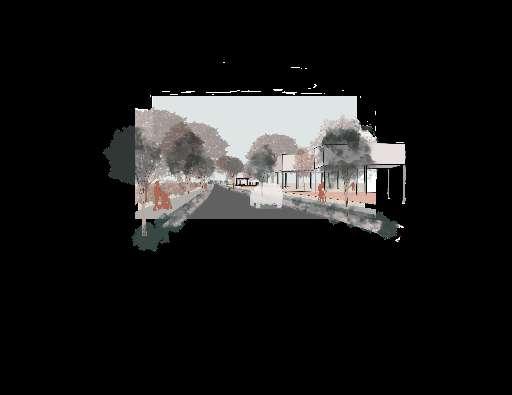
RENDERING OF STORFRONT

01
EAST BILOXI CULTURAL CENTER
Blue Economy Urban Design & Mixed-Use Development Studio IVA | Fall 2023 Semester | Biloxi, MS
Client: Gulf Cost Community Design Studio (GCCDS)
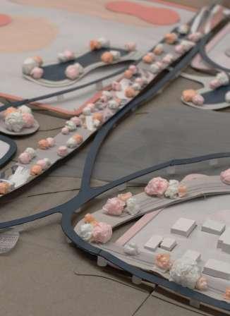
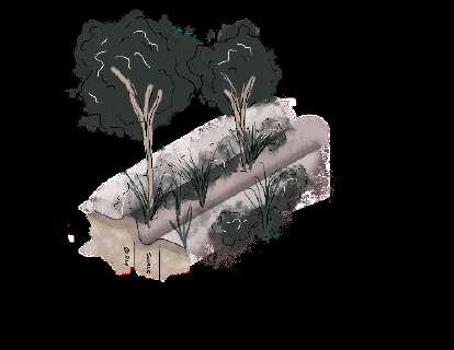
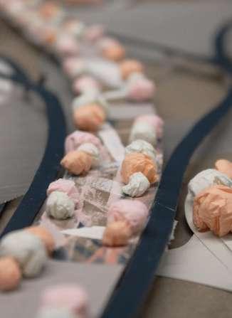
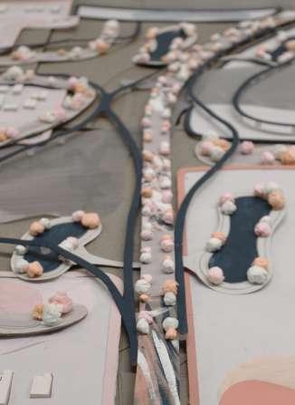
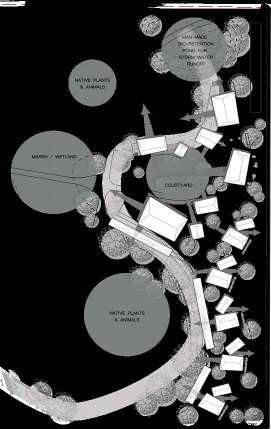
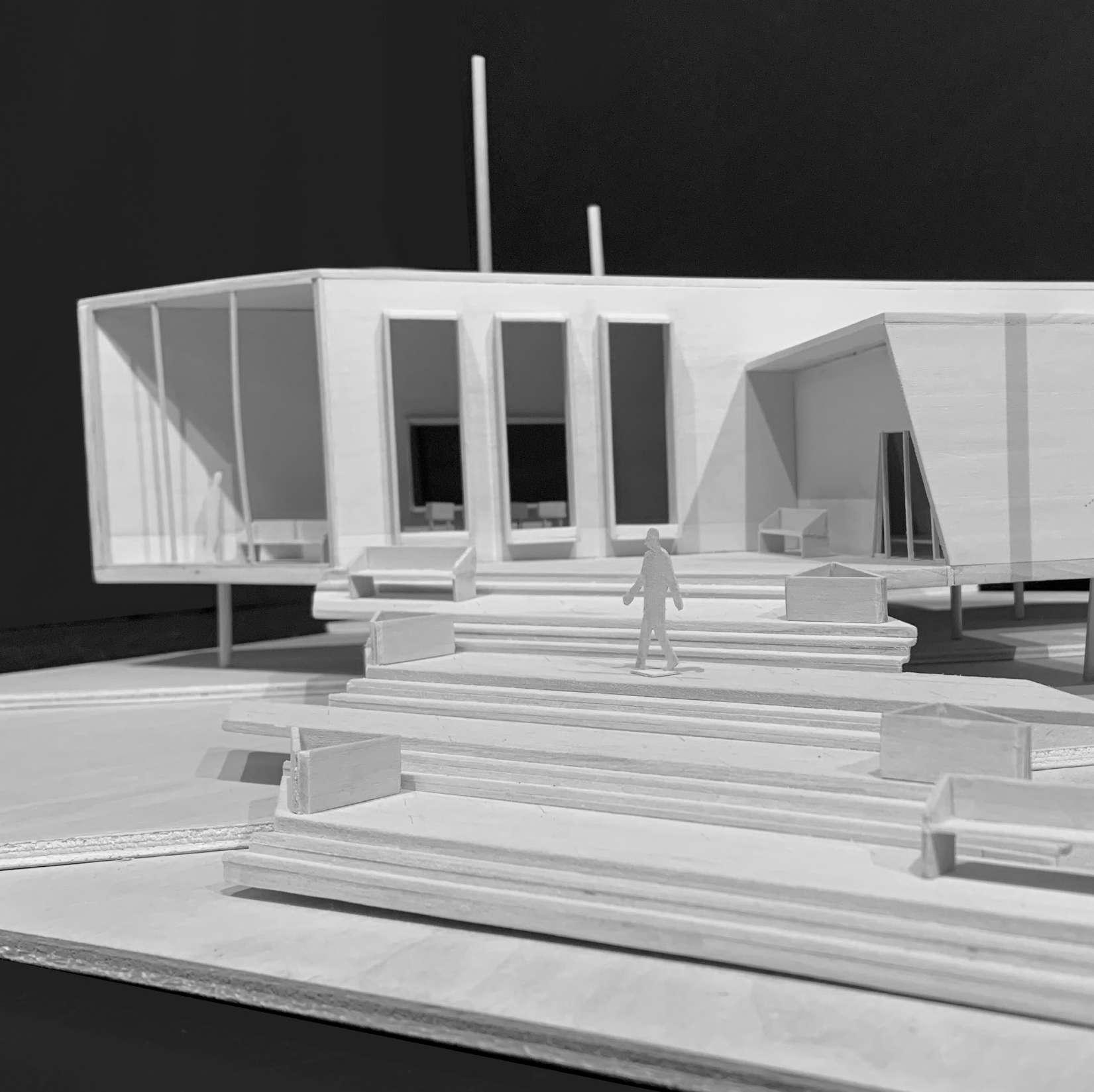
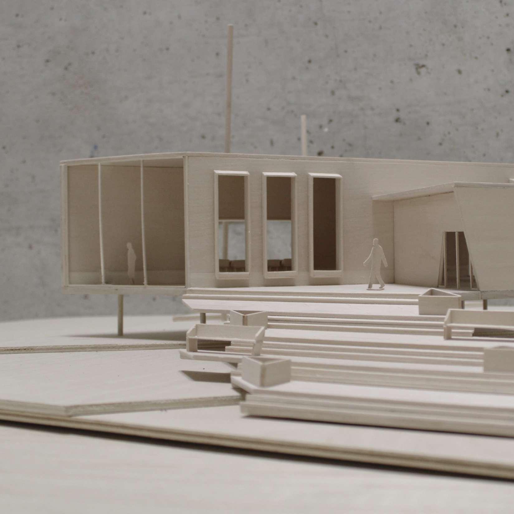
The overall goal for this building is to provide resources, opportunities, and knowledge to the community about how they can involve themselves to ensure their safety and their protection of the marsh. The nature and ecosystem that make up my selected site are just as much a design feature as the typology’s architectural features. The masses that make up the system are individual typologies that apply to their functions, and all the masses are connected by a decking system. This is done to experiment with the boundaries of natural and built environment. The intent of developing a building that blends with the natural environment would allow for a condition where the community can come together, and the wetland ecosystem can thrive harmoniously. This system allows for a true relationship between the built and natural environment. I believe that a blur between these two builds a trust for the people in the community, where a deeper understanding of the protective nature of the surrounding environment is made.
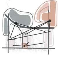
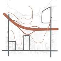
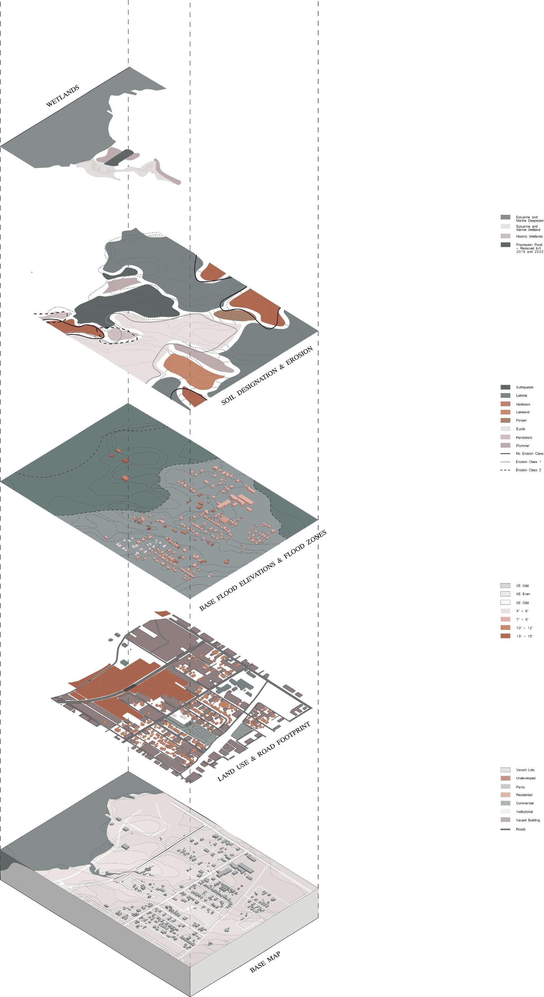
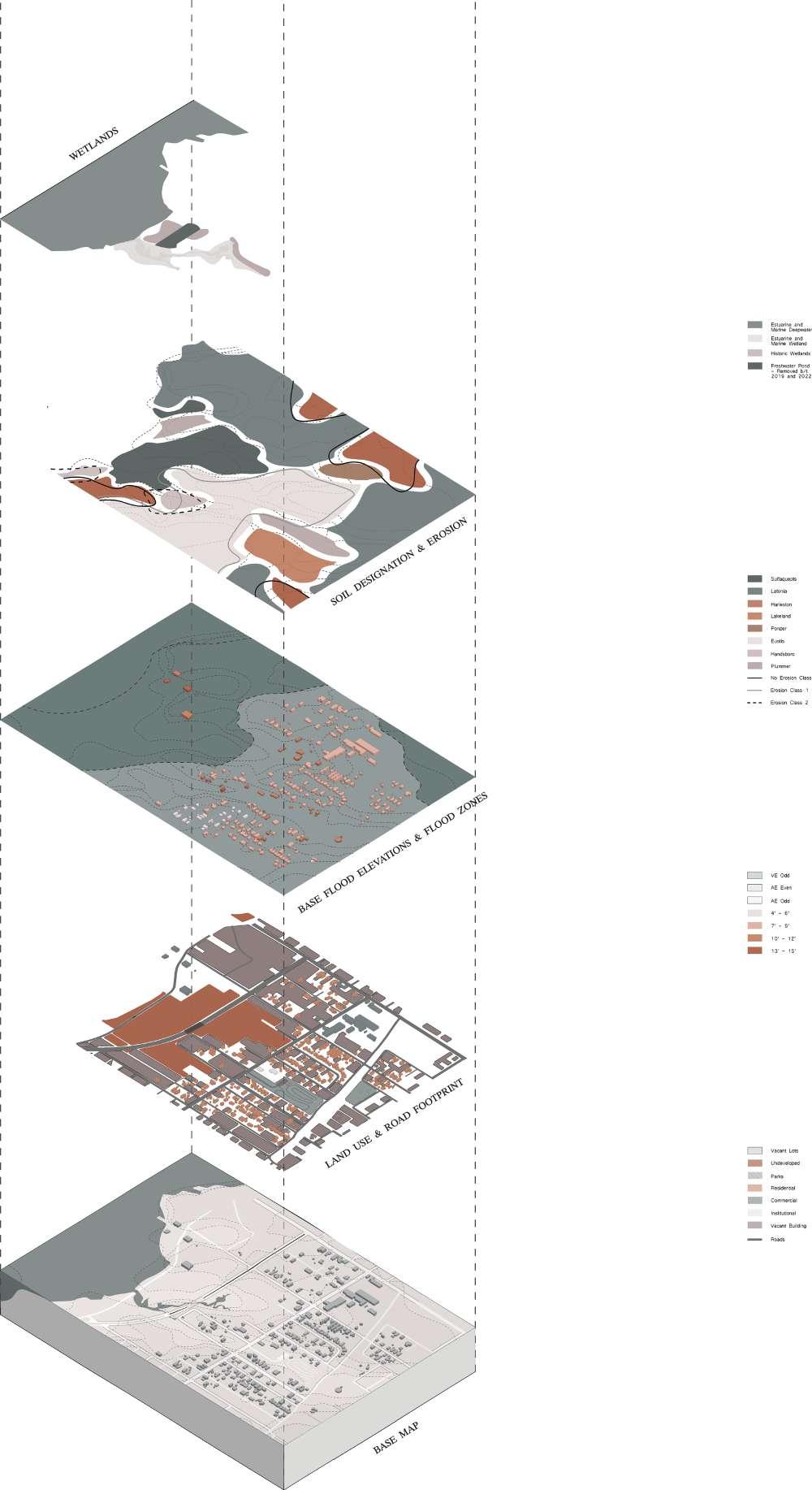
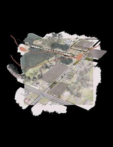
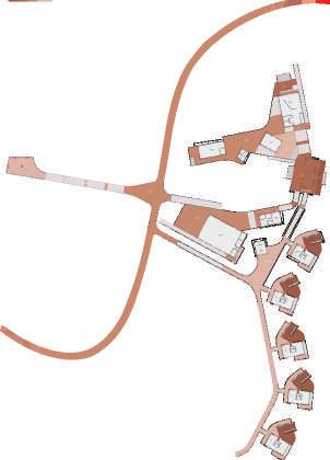
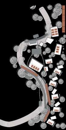
 EXPLODED AXONOMETRIC OF SITE ANALYSIS OF LOW ZONE IN BILOXI, MS
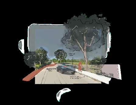
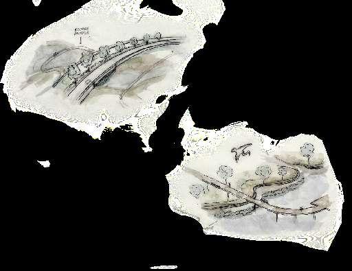
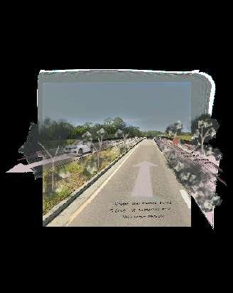
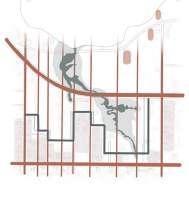
BACK BAY BLVD Boardwalk that overlooks parts of the marsh and living shoreline Preliminary Sketch of Back Bay Blvd. Began to consider pedestrian bridges connecting to it. How do you incorporate pedestrian use with vehicular transportation? Incorporating green infrastructure directly into the neighborhoods. This brings protection and green space into these neighborhoods Looking at spaces like the HIghline in New York inspired a greenway that links the community STRANGIAVE GREEN INFRASTRUCTURE Approach to mitigate flooding: berm and swale system to create a natural protective barrier. Using New & Existing Infrastructure Sketch showing the availability of land on the East side of the site. Also showing the green infrastructure proposal around the marsh. Change the four lane road to two lanes and incorporate walking spaces to encourage pedestrian traffic. PEDESTRIAN PATHS CONNECTING COMMUNITY CLOSE-UP VIEW OF BRIDGE BRIDGE & WATER MANAGEMENT SOLUTION
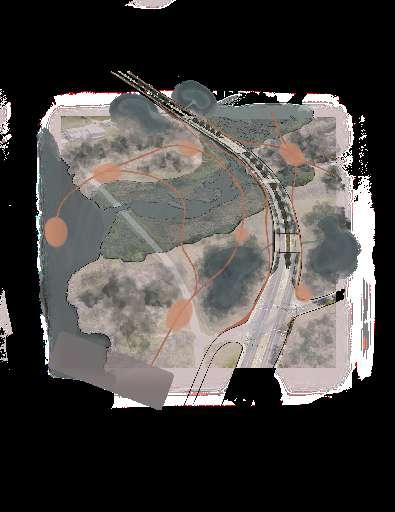
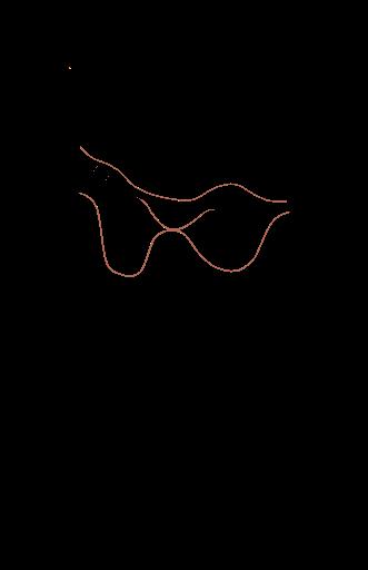
APPROACH TO INCORPORATING
CONCEPTUAL COLLAGE OF URBAN DESIGN SOLUTIONS AND
GREEN ECONOMY TECHNIQUES


5
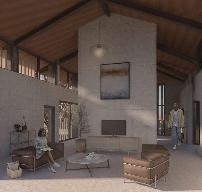
VIEW OF RESIDENTIAL DECK
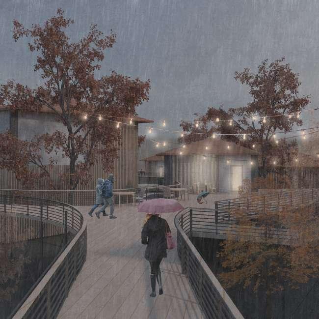
VIEW ON DECK OUTSIDE OF CLASSROOM
INTERIOR VIEW OF RESIDENTIAL TYPOLOGY
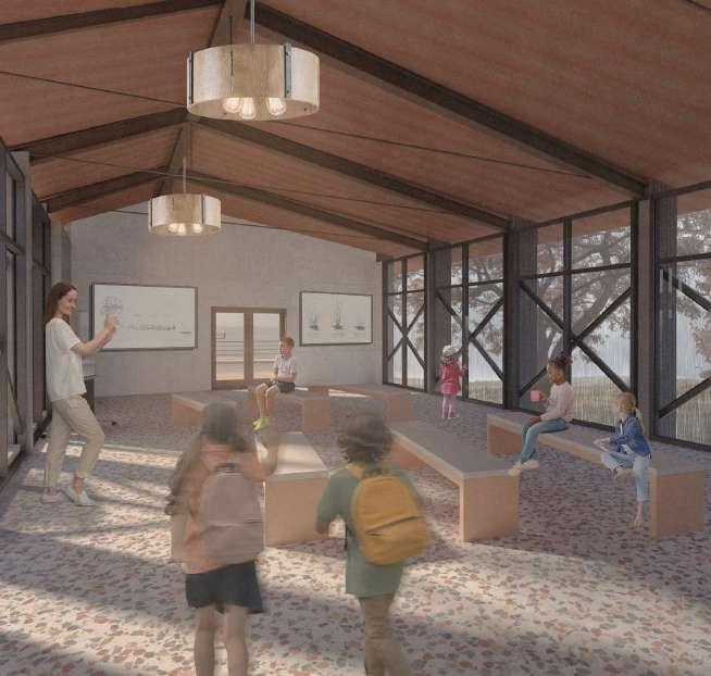
INTERIOR VIEW OF CLASSROOM AND RAIN VEIL
1. TRANSITIONAL CLASSROOM
2. STORAGE
3. ADMIN LOBBY
4. RESTROOM
5. ADMIN OFFICE
6. LIBRARY
7. ELEVATED LIBRARY SEATING
8. EXPLOREUM LOBBY
9/10. RESTROOM
11. STORAGE
12. ENVIRONMENTAL EXPLOREUM
13. OUTDOOR CLASSROOM
14. OUTDOOR PLAYSPACE
15.COURTYARD DECK
16. ENTRY PAVILION
17/18. RESTROOM
19. ENTRY SEATING DECK
20. COURTYARD
21. RESOURCE LOBBY/LOUNGE
22.RESTROOM
23/24. RESOURCE OFFICE
25. STAFF BREAKROOM
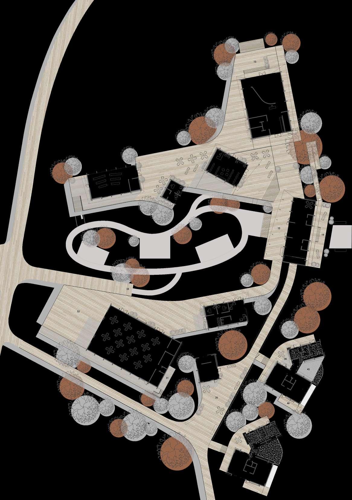
FLOOR PLAN
26. EVENT SPACE (INTERIOR)
27. STORAGE
28/29. RESTROOMS
30. JANITOR’S CLOSET
31. MECHANICAL DECK
32. EVENT SPACEE (EXTERIOR)
33. COMMUNITY BOARDWALK
34. RESIDENTIAL LOUNGE
35. RESIDENTIAL BOARDWALK
36. DECK / OUTDOOR LIVING
37. KITCHEN
38. DINING ROOM
39. BATHROOM
40. ELEVATOR
41. LIVING ROOM
42. BEDROOM 1
43. BATHROOM
44. BEDROOM 2
45. PATIO
46. FRONT PORCH DECK
BOARDWALK HEIGHTS
VIEWSHEDS
ENERGY AND WATER SOLUTIONS
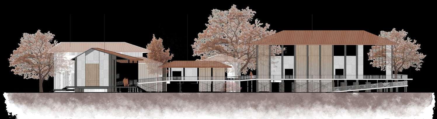
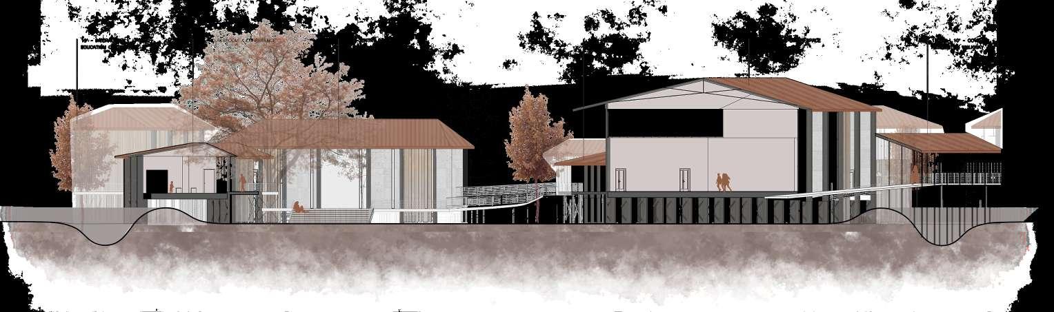
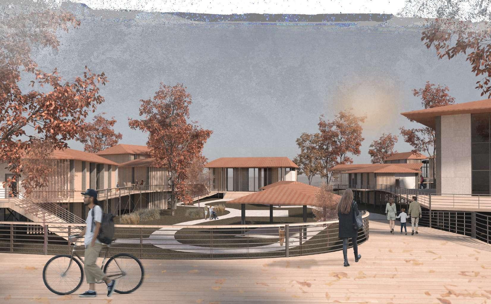
RENDERING OF PEDESTRIAN BOARDWALK SECTION SHOWING COURTYARD SECTION THROUGH AXIS OOF SITE 7
10" DIAMETER PILOT POINT / TOE 3" PITCH HELICAL PLATE DESIRED SOIL STEEL PIPE PILE SHAFT 4 1/2" DIAMETER WELDED TO SHAFT HELICAL PLATE ENERGY EFFICIENT 2 1/4" INSULATING AIR CAVITY W/ ARGON GAS EXTERIOR TEMPERED GLASS PANE PVB INTERLAYER DESICCANT METAL SPACER INTERIOR LAMINATED AND TINTED HEAT STRENGTHENED GLASS PANES HANDLE FOR OPERABLE WINDOW 4 1/2" DIAMETER BRACKET SLEEVE 7" INTO PILE CAP T-CAP BOLTS GUSSET WELDED CONNECTION STEEL BRACING 4'6" X 1'6" CONCRETE FOOTING 12" DIAMETER HELICAL PLATE PLATE EXTENSION BRACKET LEAD PIILE W/ HELICAL 3/4" BOLTED COUPLING CONNECTING EXTENSION Z PURLIN (2'6" O.C.) CLEAT STANDING SEAM ROOFING STRUCTURAL STEEL RAFTER 6" 4" END PLATE HAUNCH CONNECTION WEB STIFFENERS SPRAYED POLYURETHANE FOAM INSULATION GYPSUM BOARD 1/2" FIBER-REINFORCED GYPSUM EXTERIOR SHEATHING 1 1/2" METAL HAT CHANNEL SPRAYED POLYURETHANE 1/2" WATER BARRIER STEEL COLUMN COLUM 8" x 36" 12" 24" RECTANGULAR BEAM GROUTED IN HOLE DOWEL BAR EFFICIENT DETAILPHOTO OF BUILDING DECK EXTERIOR PHOTOGRAPH OF SECTION MODEL WALL SECTION OF TYPOLOGY
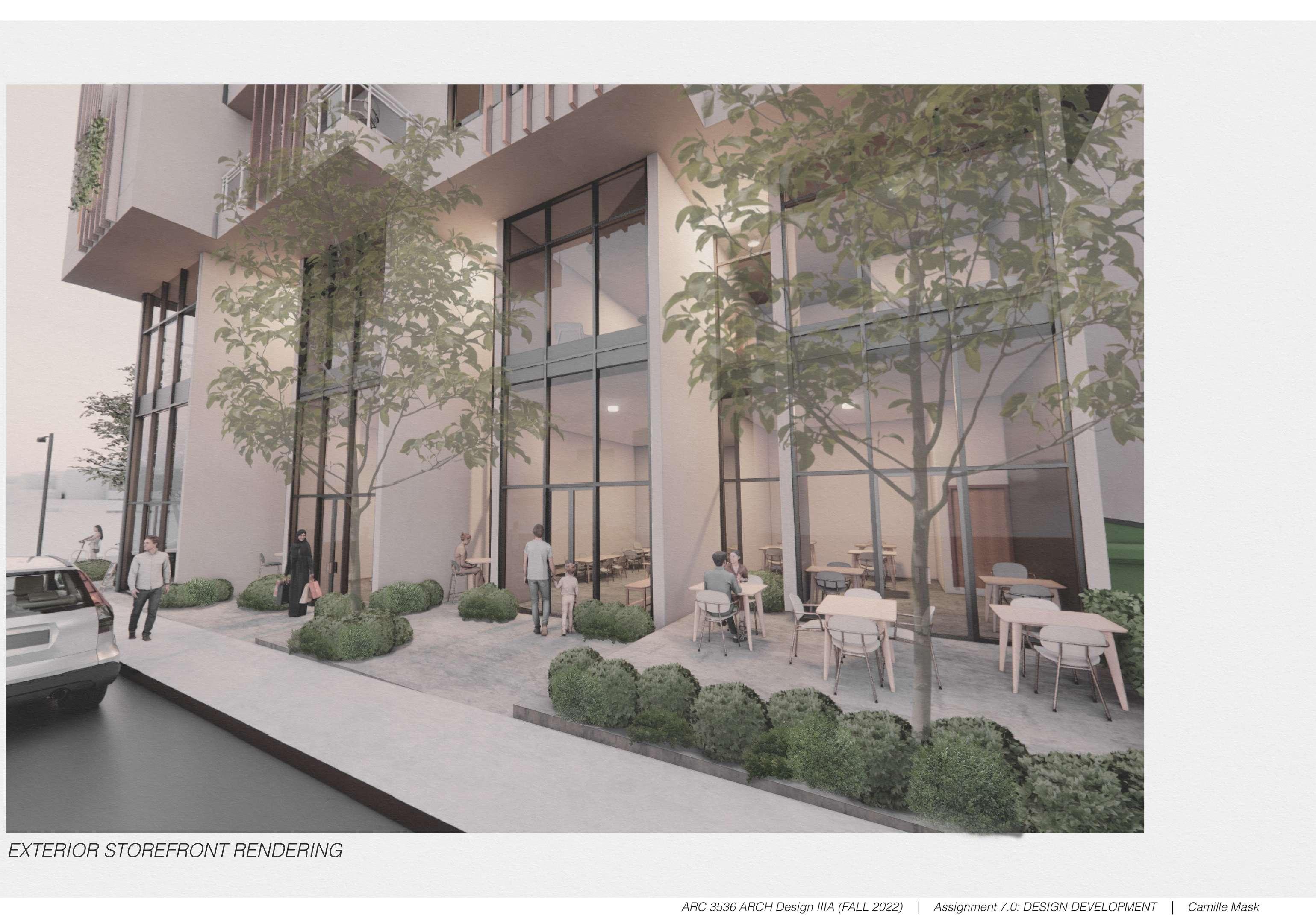
RENDERING OF STORFRONT
02
THE LOOM
Experimental Housing and Urban Mixed-Use Development
Studio IIIA | Fall 2022 Semester | Mempis, TN
Client: Mississippi State University
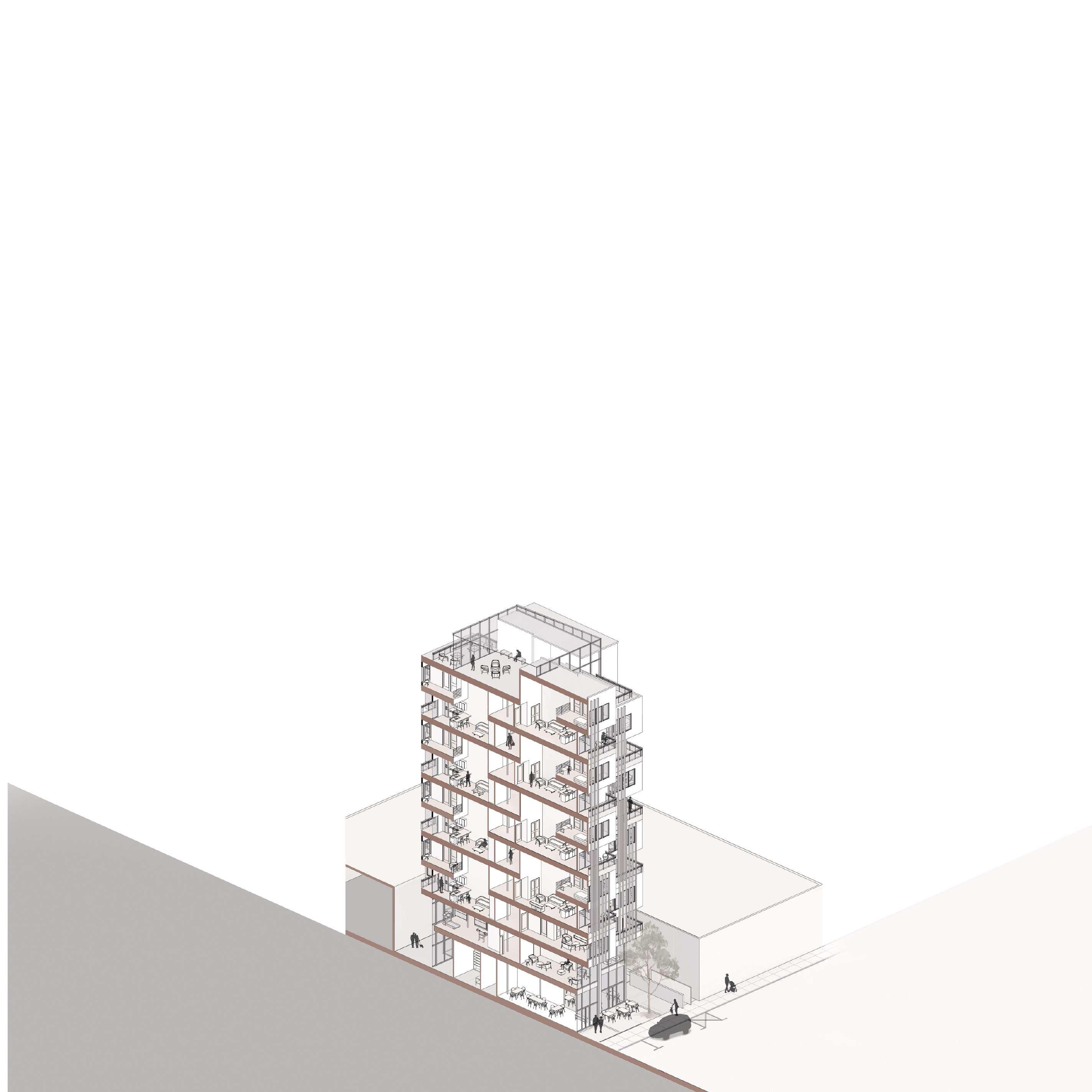
This project was focused on providing housing for the community, while introducing commercial space. Creating a comfortable outdoor space for the community of Memphis became a large focus for my project and drove my initial concept. The form of the building was established from a grid and through the action of staggering and shifting shapes in response to my consideration of site usage. The masses of the individual apartment units weave into each other and stagger away from the property line to create the building’s form and the condition on the ground level. The title ‘The Loom’ was inspired from the fabric of my design through its interlacing of masses to create its form and facade. ‘The Loom’ symbolizes the methodization of compartments into a whole through the process of interconnecting and interlacing. The design prioritizes a unique experience for all with its varying conditions of circulation, and allows the weaving of the paths of residents and the community while maintaining privacy for its residents.
3.
2.
1.
The
5. REPEAT
3. SHIFT The
3.
4.
5.
N B B K I N G B L V D JEFFERSON AVE 1 2 16 17 18 19 20 21 8 9 10 11 12 13 15 17 20 14 11 11 3 4 5 6 7 1. ELEVATOR 2. FIRE STAIRS 3. RESIDENTIAL 4. BIKE STORAGE 5. LOBBY 6. OFFICE 7. MAIL ROOM 8. RESTROOM 9. RESTROOM 10. RESIDENTIAL 11. OUTDOOR 12. MECHANICAL 13. GARBAGE CHUTE 14. FIRE STAIRS 15. GARBAGE PICKUP 16. SERVICE HALLWAY 17. RESTAURANT 18. STORE / BOUTIQUE 19. CAFE 20. OUTDOOR SEATING 21. RESIDENTIAL 11 GEOMETRY OF DESIGN 1. ESTABLISH A GRID AND FORMS The grid was determined by the size of the site. The rectangles are based on the unit sizes and the use of space 2. SHIFT AND STAGGER The four rectangles use for commercial and residential square footage on the site were shifted to create a setback for more space on the site. 3. SHIFT The rectangle for circulation is reincorporated to push the rectangles together to optimize space on the site. 4. VERTICAL GRID The grid continued on the sides of the form as projected my units up. The grid also divided commercial and residential space sbased on floors.
REPEAT I used the grid to create repeated rectangles that represent the units. They started as two rectangular prisms and then were arranged alternating two sizes. By shifting these into the created form, this created an additional staggered condition. GRID AND FORMS determined by the size of the site. based on the unit sizes and the 2. SHIFT AND STAGGER The four rectangles use for commercial and residential square footage on the site were shifted to create a setback for more space on the site.
SHIFT The rectangle for circulation is reincorporated to push the rectangles together to optimize space on the site. the sides of the form as The grid also divided comspace sbased on floors.
5.
3.
used the grid to create repeated rectangles that represent the units. They started as two rectangular prisms and then were arranged alternating two sizes. By shifting these into the created form, this created an additional staggered condition. STAGGER commercial and resithe site were shifted to space on the site.
rectangle for circulation is reincorporated to push the rectangles together to optimize space on the site. repeated rectangles that represent the units. They started as two rectangular prisms and alternating two sizes. By shifting these into the created form, this created an additional stag-
GEOMETRY OF DESIGN
ESTABLISH A GRID AND FORMS
grid
determined by the size of the site. The rectangles are based on the unit sizes and the use of space
was
SHIFT AND STAGGER The four rectangles use for commercial and residential square footage on the site were shifted to create a setback for more space on the site.
optimize space on the site.
SHIFT The rectangle for circulation is reincorporated to push the rectangles together to
VERTICAL GRID
grid continued on the sides of the form as I projected my units up. The grid also divided commercial and residential space sbased on floors.
The
REPEAT used the grid to create repeated rectangles that represent the units. They started as two rectangular prisms and then were arranged alternating two sizes. By shifting these into the created form, this created an additional staggered condition. GRID AND FORMS determined by the size of the site. based on the unit sizes and the
SHIFT AND STAGGER The four rectangles use for commercial and residential square footage on the site were shifted to create a setback for more space on the site.
2.
SHIFT The rectangle for circulation is reincorporated to push the rectangles together to optimize space on the site. GRID on the sides of the form as up. The grid also divided comresidential space sbased on floors.
REPEAT I used the grid to create repeated rectangles that represent the units. They started as two rectangular prisms and then were arranged alternating two sizes. By shifting these into the created form, this created an additional staggered condition. commercial and resiwere shifted to the site. 3. SHIFT The rectangle for circulation is reincorporated to push the rectangles together to optimize space on the site. rectangles that represent the units. They started as two rectangular prisms and sizes. By shifting these into the created form, this created an additional stag- GEOMETRY OF DESIGN GROUND LEVEL FLOOR PLAN 1. ELEVATOR 2. FIRE STAIRS 3. RESIDENTIAL COORIDOR 4. BIKE STORAGE ROOM 5. LOBBY 6. OFFICE 7. MAIL ROOM 8 / 9. RESTROOM 10. RES. CONVENIENCE STORE 11. OUTDOOR RESIDENTIAL PATIOS 12. MECHANICAL ROOM 13. GARBAGE CHUTE 14. FIRE STAIRS 15. GARBAGE PICKUP 16. SERVICE HALLWAY 17. RESTAURANT 18. STORE / BOUTIQUE 19. CAFE 20. OUTDOOR SEATING 21. RES. ENTRANCE
5.


ELEVATION DETAIL
1.
3.
4.
5.
6.
AXONOMETRIC SECTION RESIDENTIAL FLOOR PLAN 1 5 3 4 2 6 G F E D C E C A B OTB OTB
ELEVATOR
FIRE STAIRS
2.
RESIDENTIAL CORRIDOR
BIKE STORAGE ROOM
LOBBY
OFFICE
MAIL ROOM
/ 9. RESTROOM
RES. CONVENIENCE STORE
OUTDOOR RESIDENTIAL PATIOS 13
7.
8
10.
11.
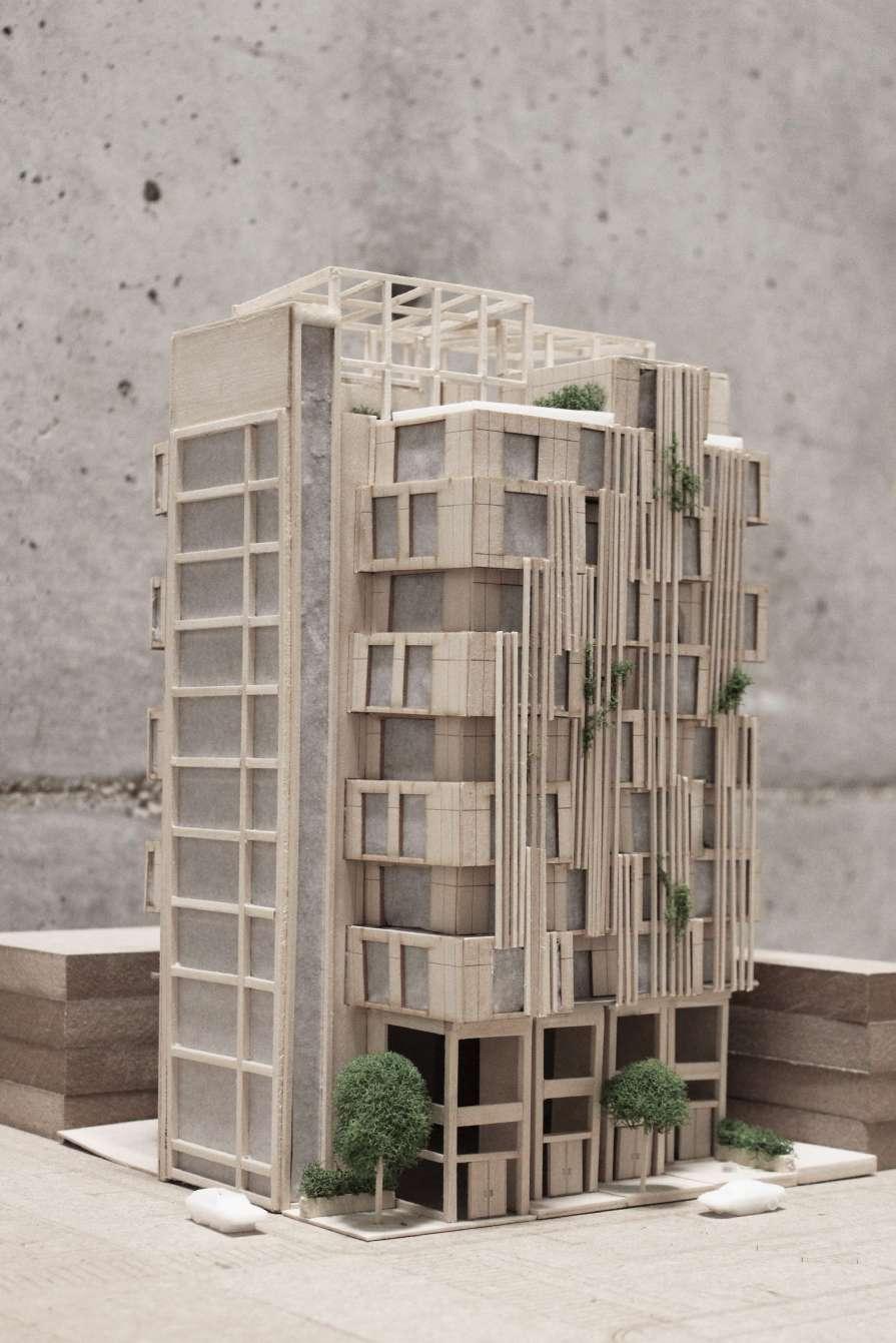 DIAGRAM OF SLAT DESIGN ON FACADE
PHOTOGRAPH OF BASSWOOD MODEL FROM STREET INTERSECTION
DIAGRAM OF SLAT DESIGN ON FACADE
PHOTOGRAPH OF BASSWOOD MODEL FROM STREET INTERSECTION
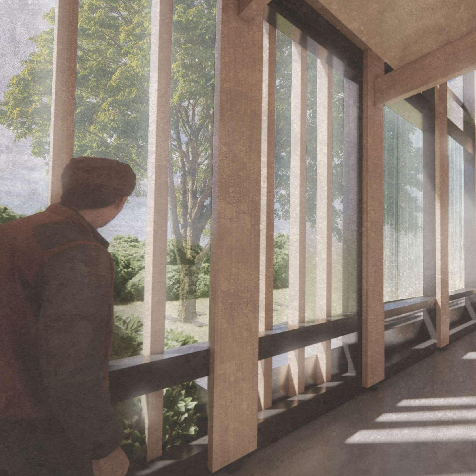
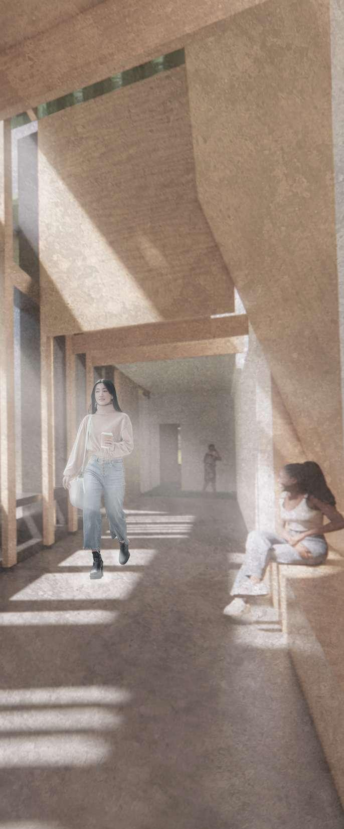
RENDERING OF CORRIDOR
03
AFRICAN AMERICAM MUSEUM OF MOUND BAYOU
Historic Preservation and Rehabilitation
Studio IIB | Spring 2022 Semester | Mound Bayou, MS
Client: Mound Bayou Historic Preservationist and Current Owners
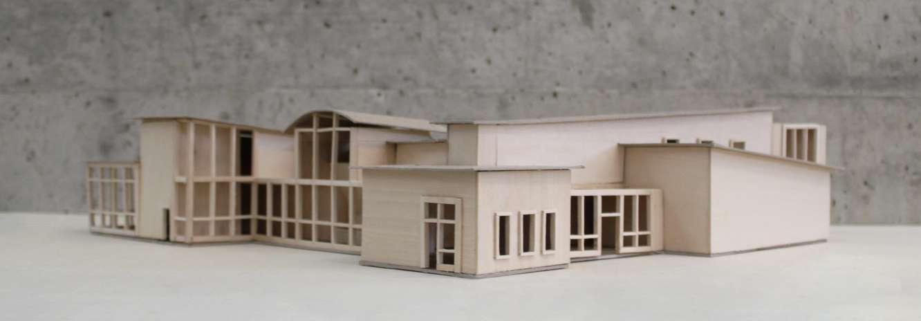
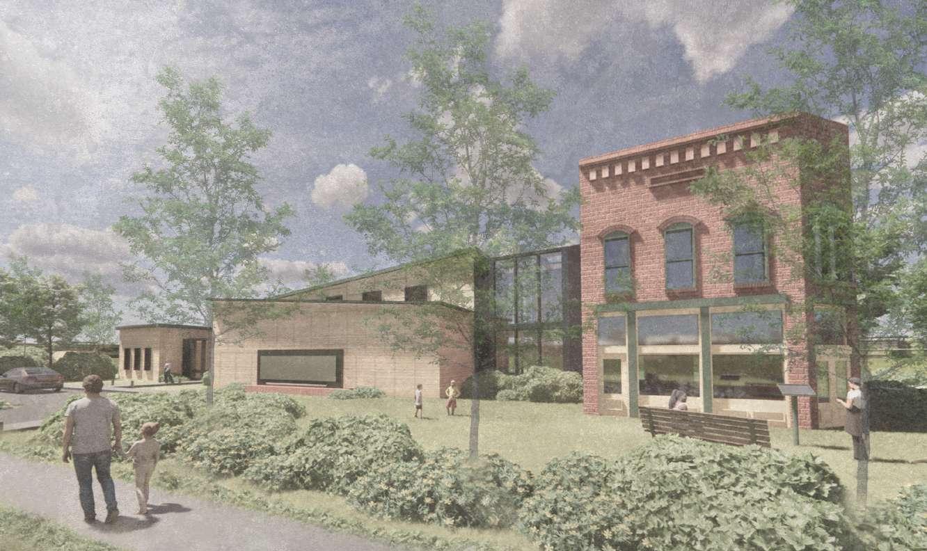
My primary objective for this project was to design an addition that pays respect to the existing historic building and the community. I approached this by selecting complementary materials to the existing building and designing a form that highlights its shape and position on the site. Knowing how important the land itself is to the project, I took the angles from the site to create my envelope shape, inspiring the rest of the design. The second floor of the building is the reverse of this angle to swiftly set the form farther behind the existing building. I designed a similar wooden column structure to existing building, but brought the wooden columns away from the wall and off the floor. Above all, my goal was to create a building that possesses its own unique features from the existing one, while still allowing it to be the primary focus. This was achieved with more than just addressing the form, as the proper balance of colors, textures, and proportions for my selection of materials were just as effective.
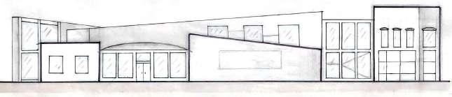
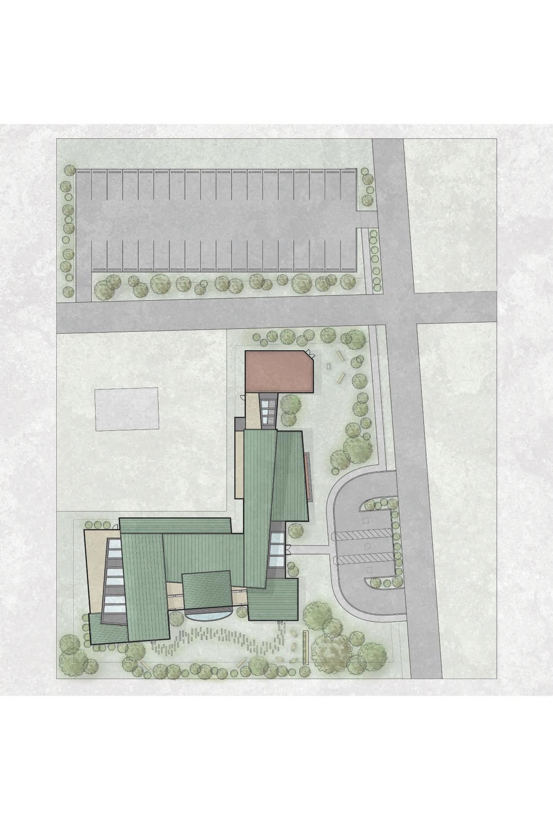

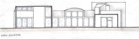
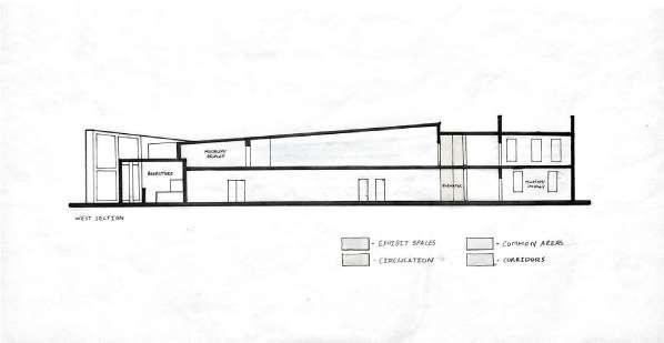
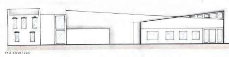
SCHEMATIC ELEVATIONS | SKETCHED 17 RENDERED SITE PLAN
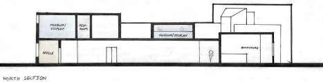
1 2 3 4 5 6 7 8 9 10 11 12 13 14 15 16 17 18 19 20 1. MUSEUM / DISPLAY 2. STAIRS 3. ELEVATOR 4. ELECTRICAL CLOSET 5. MECHANICAL CLOSET 6. JANITOR’S CLOSET 7. THEATER 8. LOBBY 9. BOOKSTORE 10. EVENT SPACE 11. MEN’S RESTROOM 12. WOMEN’S RESTROOM 13. ELEVATOR 14. FIRE STAIRS 15. CONFERENCE ROOM 16/17/18. OFFICE 19. ADMINISTRATION OFFICE FIRST FLOOR PLAN
19
EXTERIOR DAYTIME RENDERING
VIEW OF EXTERIOR | MODEL


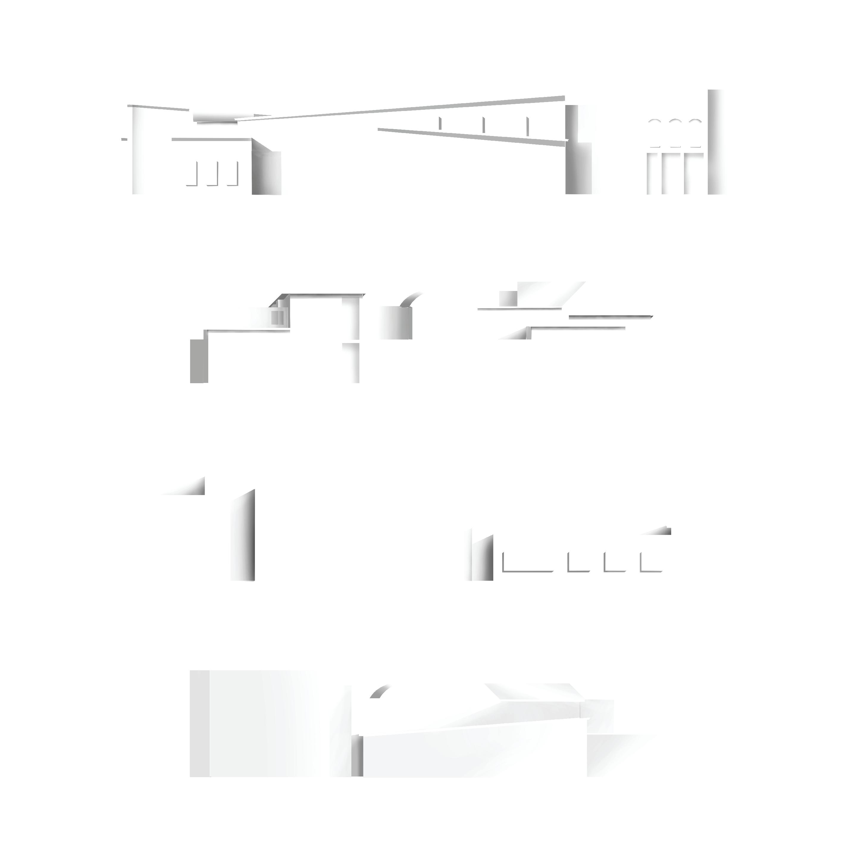
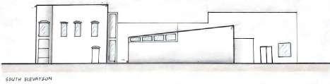
RENDERED ELEVATIONS
04
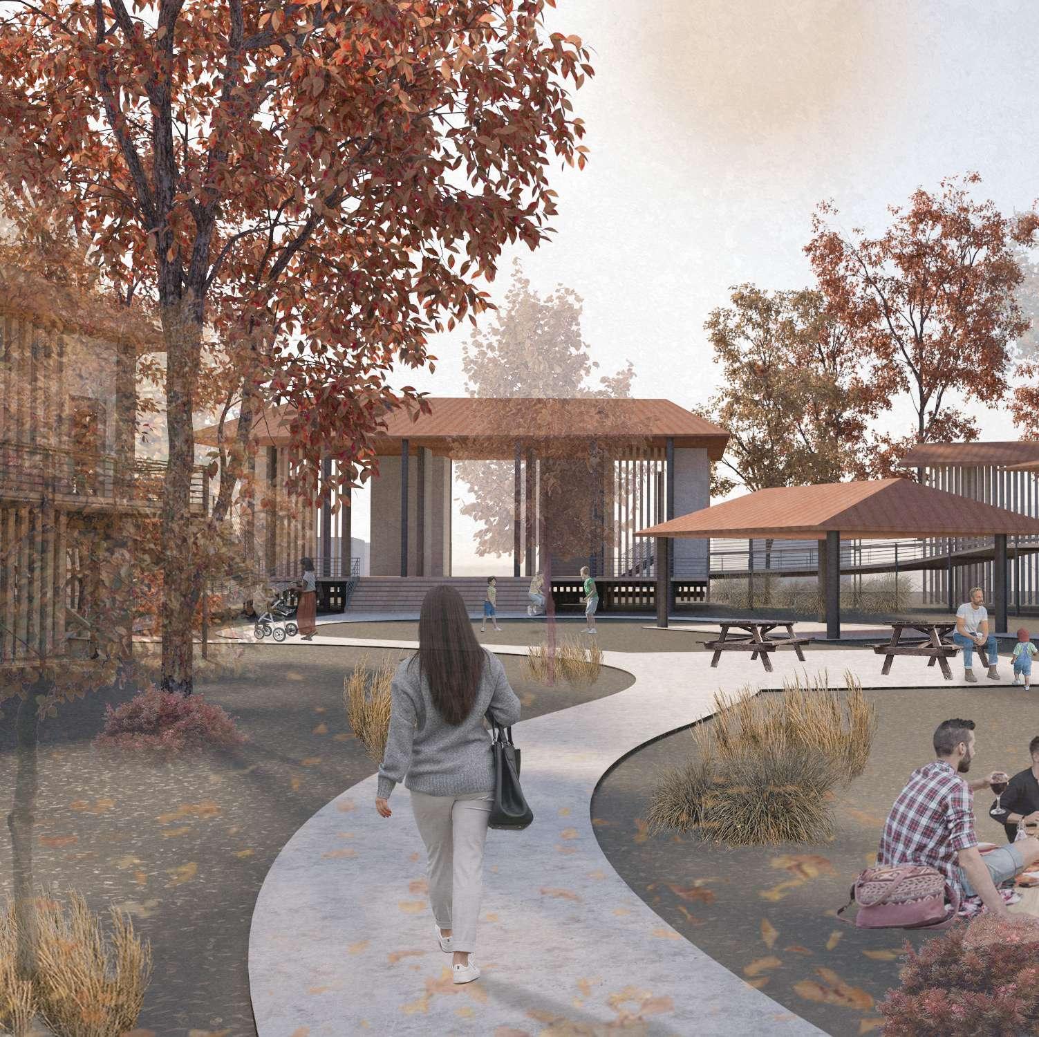
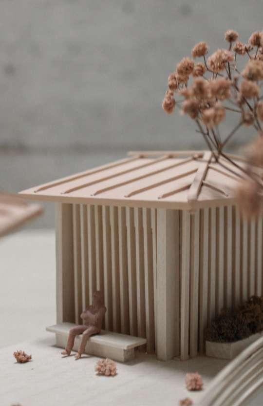
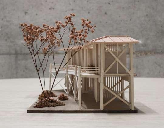
PAVILION
Rest-Stop for Nature Trail
Studio IB | Spring 2021 Semester | North Farms, Starkville, MS
Client: North Farms
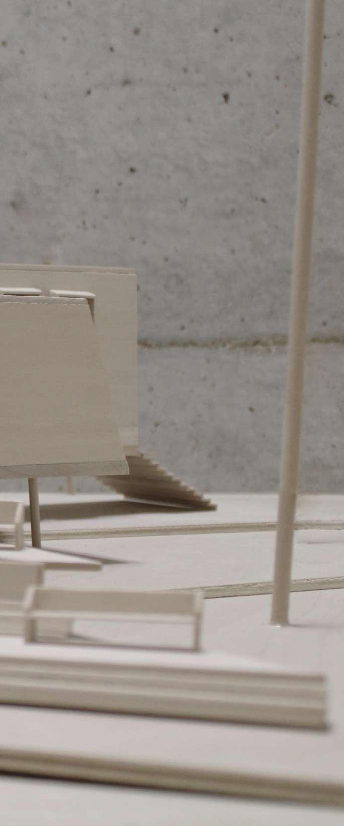
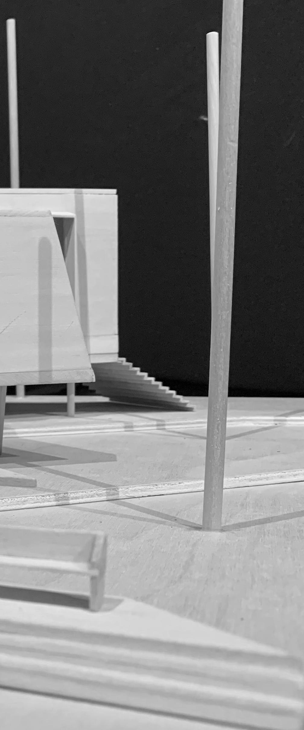
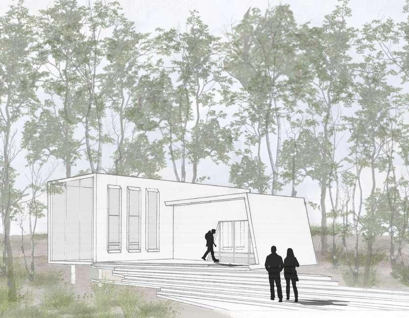
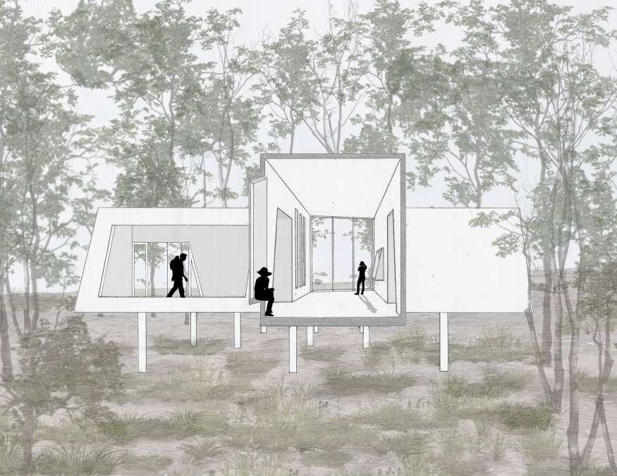
The requirement for this project was to create a rest stop for a trail in Starkville, MS. My concept for this design was to emphasize a distinction between structure and space. Because the location of the pavilion was in the woods, I found it was a great opportunity to create a building that complemeted nature on the interior. To create an interior that complemented nature, I focused on framing views through the openings. This also inspired the form and arrangement of the paviolion on the site. To create the contrasting elements, I designed my form to have sharp angles and turns that stood out amidst the forest. I also prioritized the horizontal elements of the design to constrast the vertical tree trunks. To further create a distinction, I elevated my pavilion on stilts that blend in with the tree trunks, giving the illusion that the pavilion is floating, which emphasizes its placement in the woods.
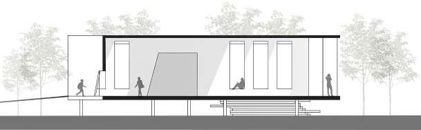
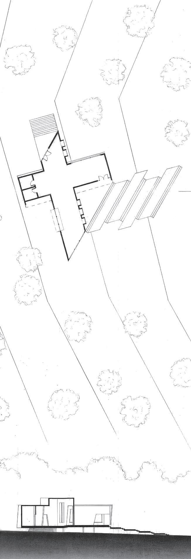
SITE PLAN AND BUILDING SECTION DRAFTED
INTERIOR RENDERING OF BUILDING DRAFTED AND DIGITAL
23
EXTERIOR RENDERING OF BUILDING | DRAFTED AND DIGITAL
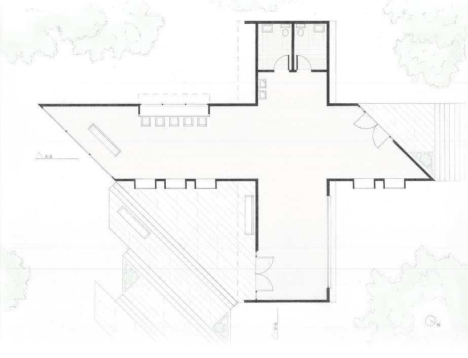
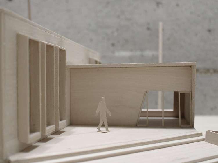
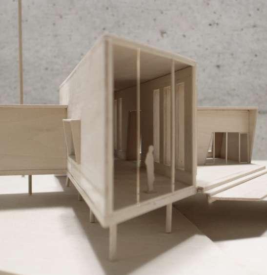 IMAGE OF EXTERIOR
|
MODEL
|
IMAGE OF EXTERIOR ENTRANCE
MODEL
PLAN | DRAFTED
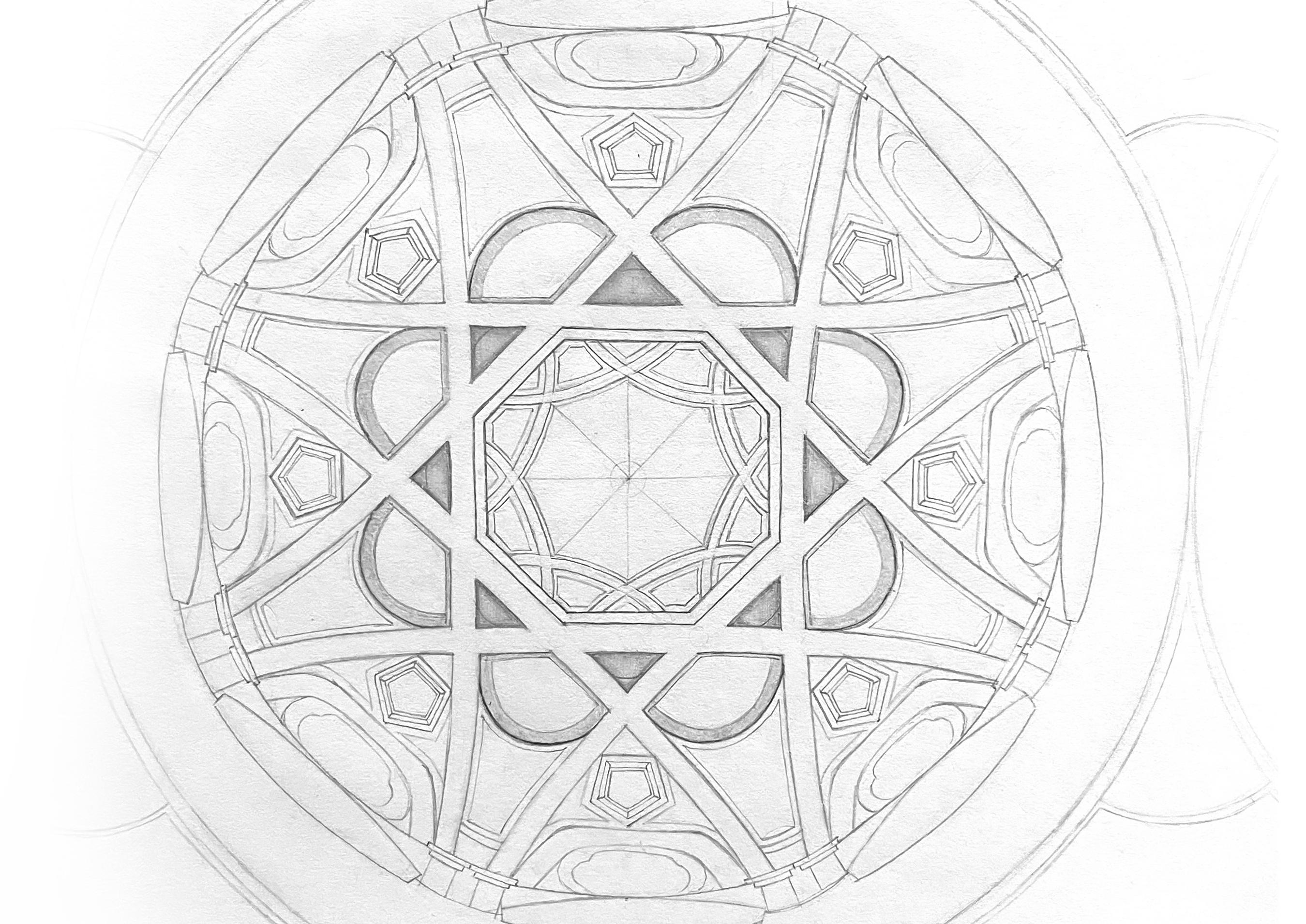
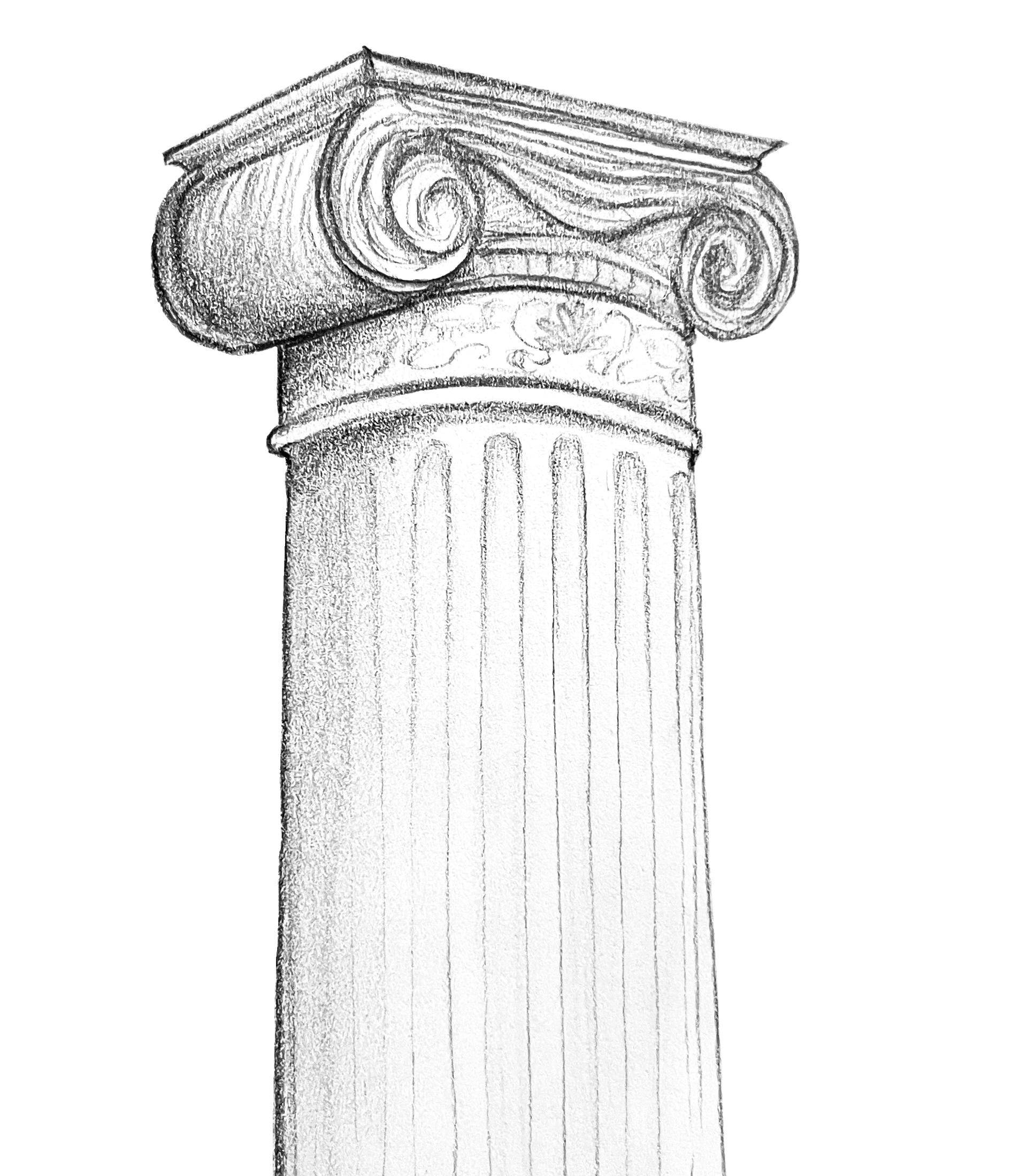
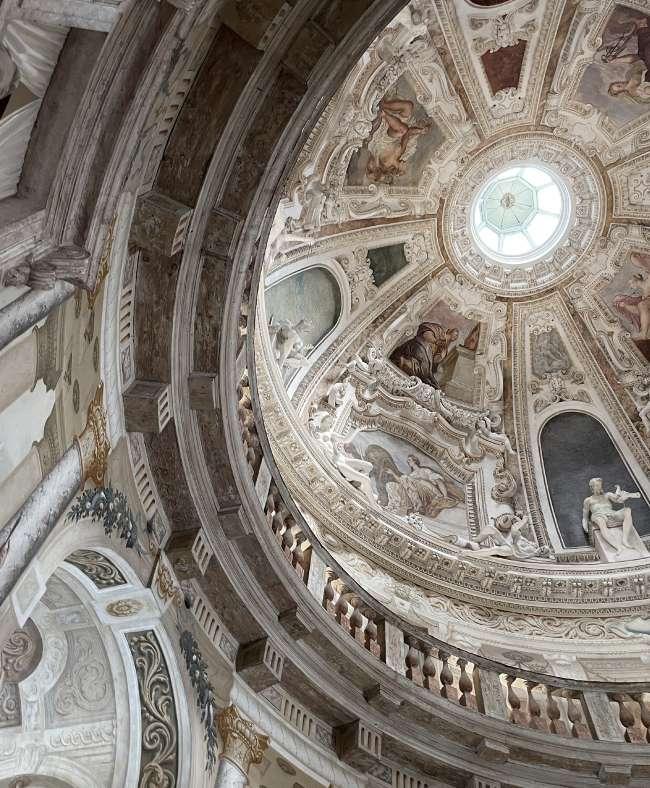
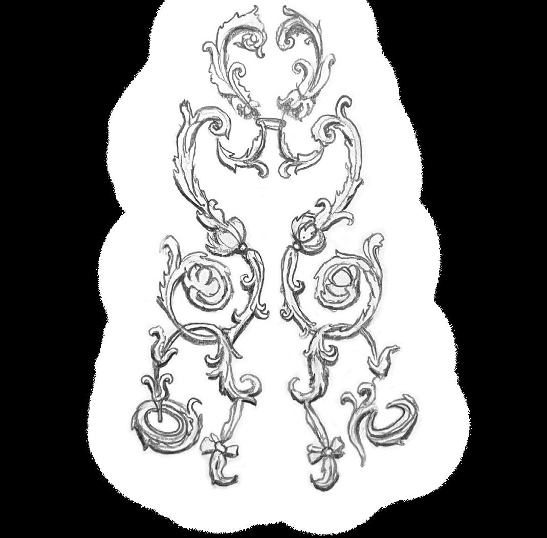
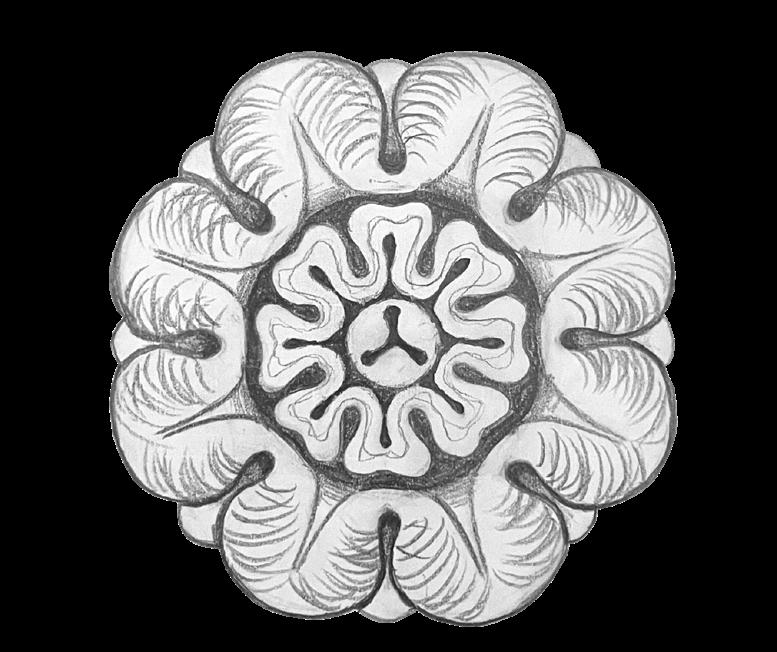
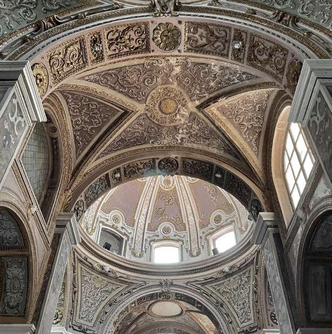
FREEHAND SKETCH OF DOME | INTERIOR VIEW
05
STUDY ABROAD: ITALY
Field Sketching | Photography | Urban Planning Studies
Summer 2022 Semester | Italy
Courses: Site Planning | Field Sketching
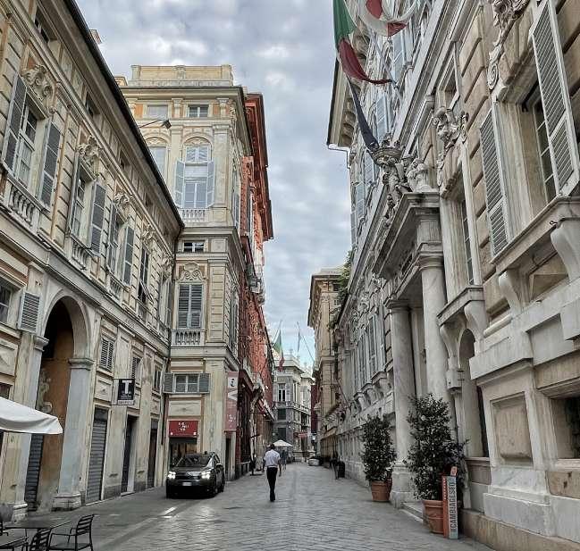
For this study abroud trip, I was able to visit various cities around Italy, being Milan, Turin, Naples, Genoa, Corniglia, Riomaggiore, Porofino, Venice, Padova, Vicenza, and Verona. I took a skethcing course and a Site Planning course where I mapped out the Via Garibaldi Street in Genoa. I had the opportunity to see architecture and art that I had only ever dreamed of.
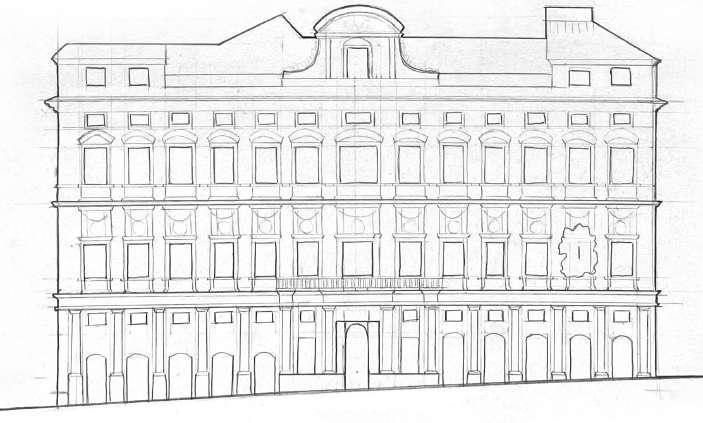
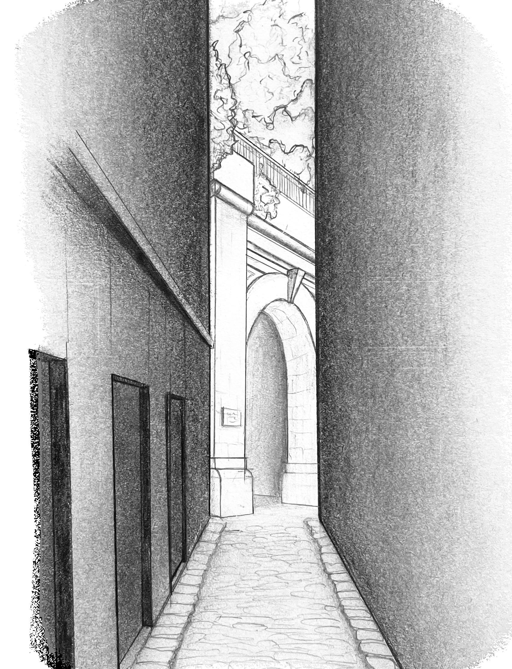
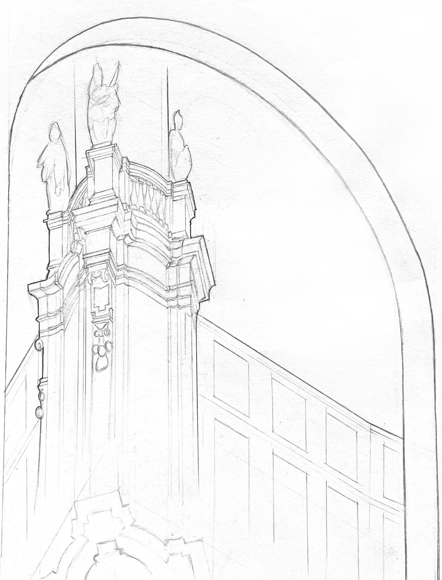
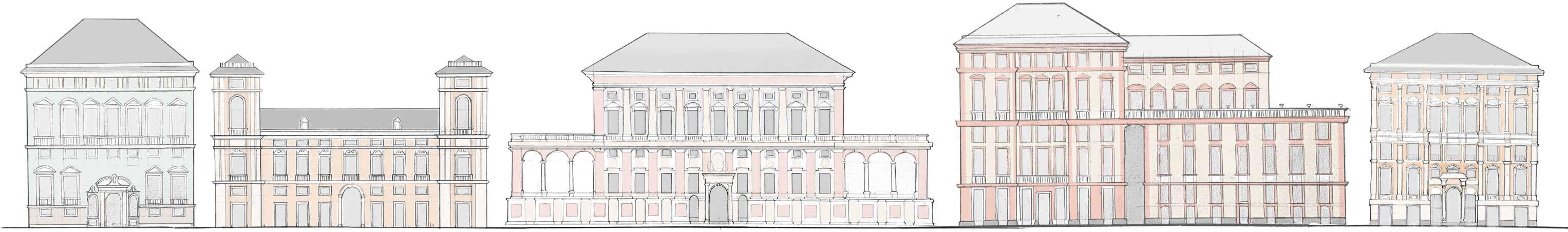
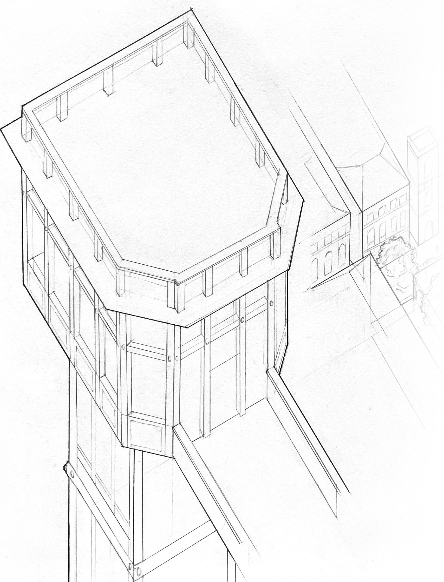
27 FACADE SKETCHES OF VIA GIUSEPPE GARIBALDI WITH COLOR APPLIED IN PHTOTSHOP ATMOSPHERIC PERSPECTIVE OF ALLEY IN GENOA SECTIONAL AXON ON OF PALACE IN GENOA V G V G
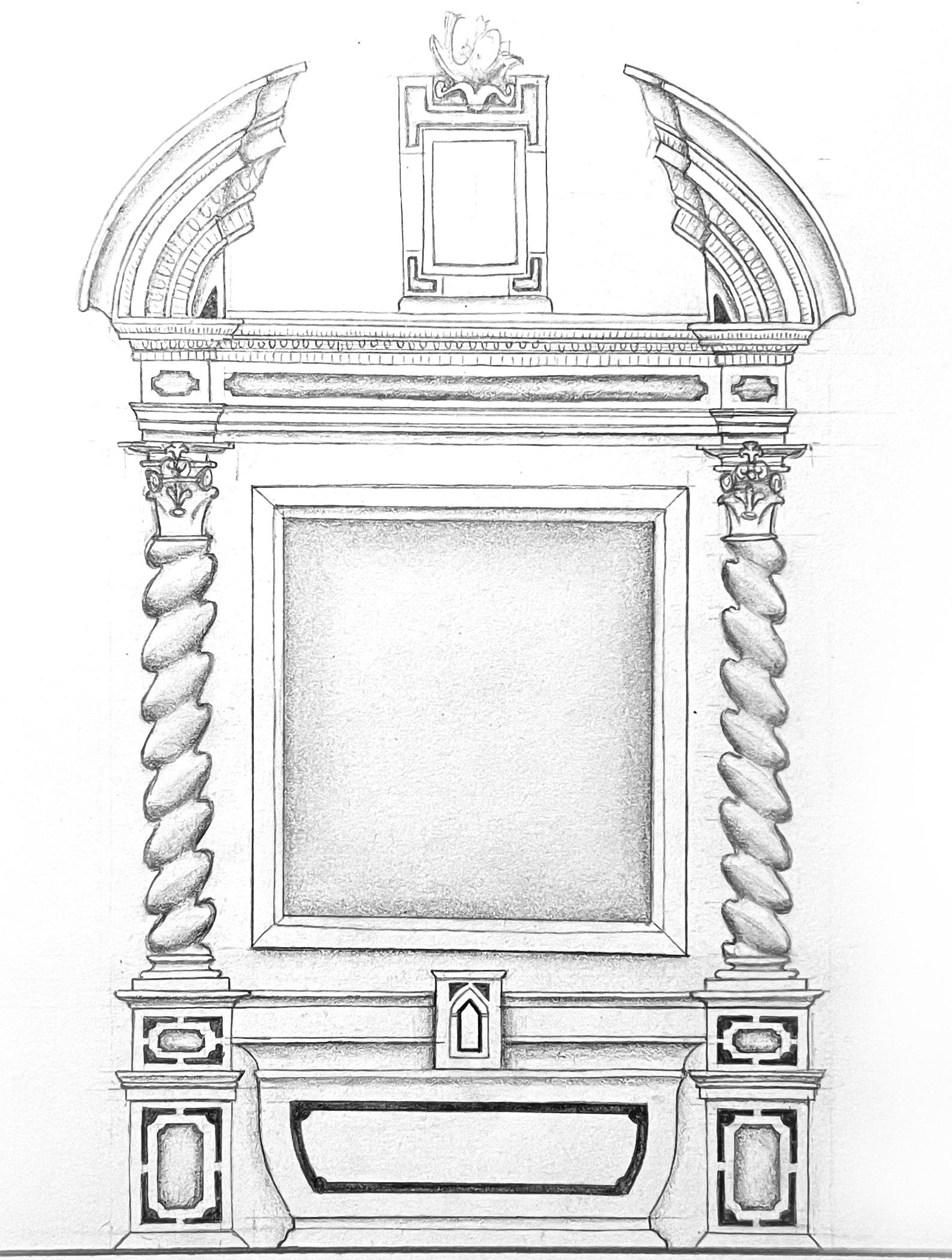
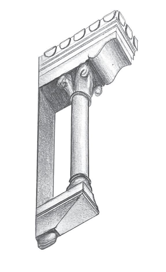
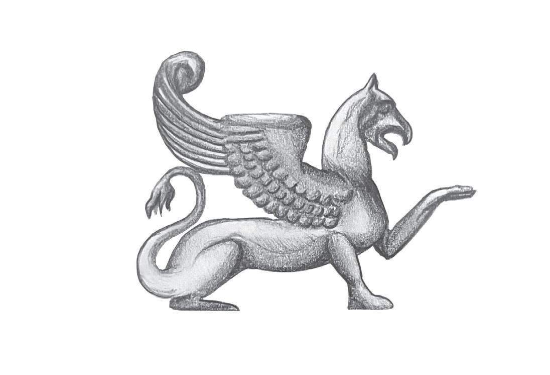
ATMOSPHERIC SKETCH OF DOORWAY IN GENOA INTERIOR ELEVATION OF ALTAR IN CORNIGLIA b ld b ld
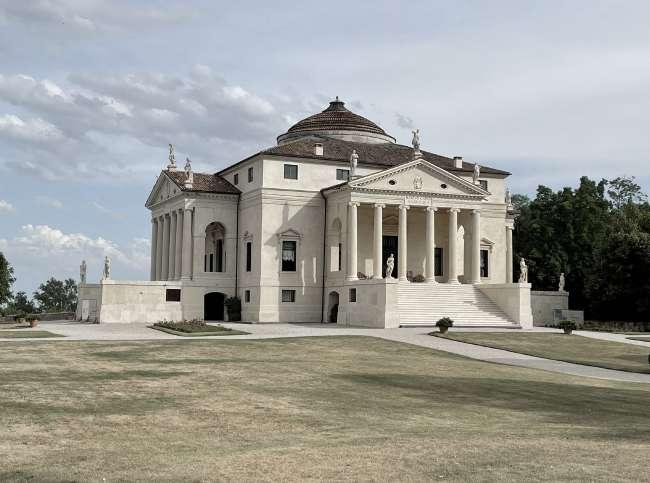
 VILLA LA ROTUNDA VICENZA
VILLA LA ROTUNDA VICENZA
VILLA LA ROTUNDA VICENZA
29
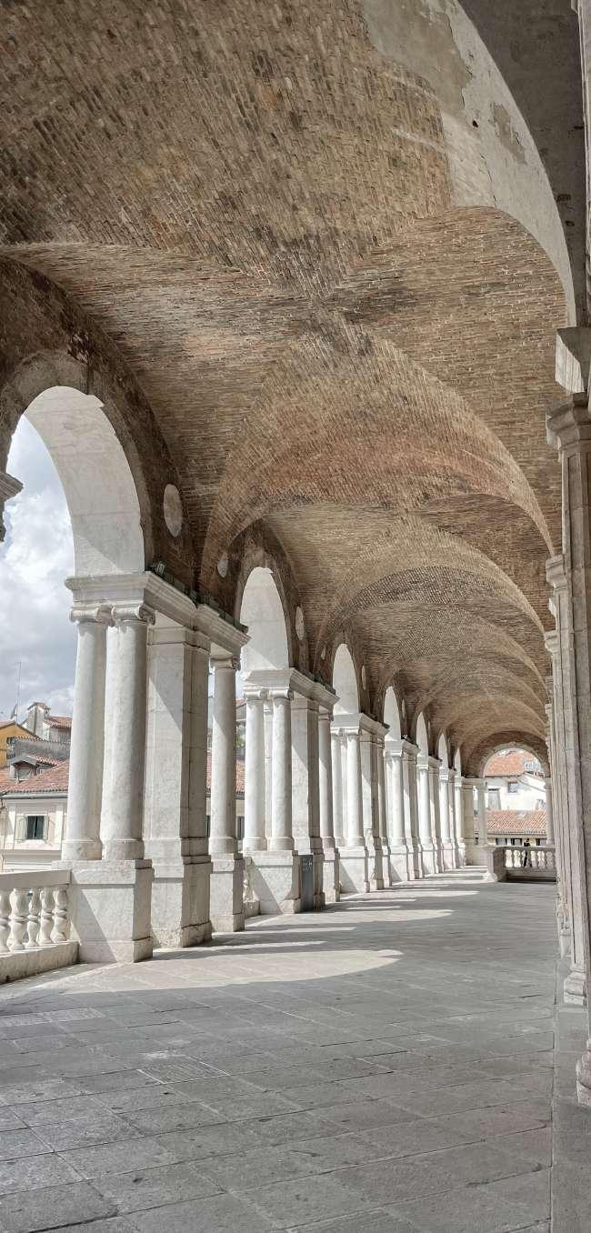
PALLADIO’S BASILICA VICENZA
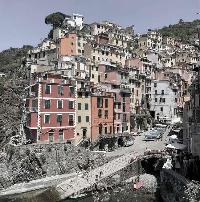
 PIAZZA SAN GAETANO NAPLES MARINA DI RIOMAGGIORE | RIOMAGGIORE
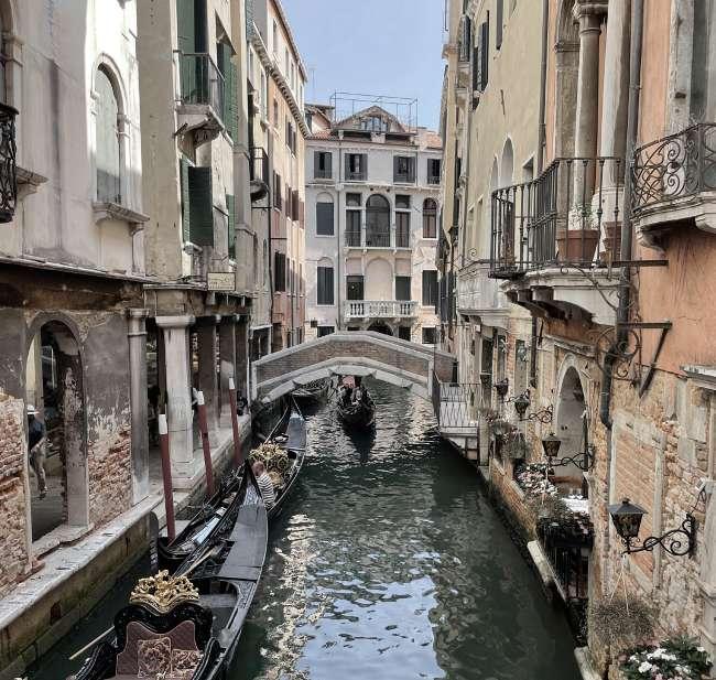
PONTE DEI BARETERI | VENICE - SAN MARCO
VIA GIUSEPPE GARIBALDI | GENOA
PIAZZA SAN GAETANO NAPLES MARINA DI RIOMAGGIORE | RIOMAGGIORE
PONTE DEI BARETERI | VENICE - SAN MARCO
VIA GIUSEPPE GARIBALDI | GENOA
