
Owen Fantuzzi
Senior Thesis | 2025

Name: Owen Fantuzzi
BUA Thesis Advisor: Dr. Srdjan Divac
Lab Thesis Advisor: Dr. Andrew Bennett
3 March 2025
Exploring the Implications of Light-Based Communications Through SeaPerch II
Abstract
Launched in 2003, SeaPerch is an underwater robotics platform designed at MIT Sea Grant as a foundation for students to learn about and develop marine ROVs (Remotely Operated Vehicles) (Bennett et al., 2024). While SeaPerch 2 features more functionality than SeaPerch 1 sporting an onboard microcontroller and various sensor modules, it utilizes a tether to transmit data and control information to and from a remote controller on land. During the summer of 2024 I, along with fellow high school student Nathan Wu, worked on a solution that mitigates the need for a tether through a light-based communication system. With our system, SeaPerch 2 is more maneuverable and can traverse longer distances without requiring a lengthy wire. This wireless communication system has additional applications including wireless underwater transmission and the ability to communicate using light rather than radio waves. Through the development of waterproof sensor enclosures and a Morse code-based signaling system, small-scale testing has yielded positive results. Initially, numerous light sensor types such as photoresistors, phototransistors, and photodiodes were tested along with various LED types for maximum range and accuracy. A base SeaPerch 2 frame was then designed and built from the ground up to accommodate our waterproof sensor modules which was designed using CAD (Computer Aided Design) and 3D printed using a resin printer to eliminate pores and leakage. Next, code was
implemented to relay information and track a light source which was ultimately tested in our lab’s 3000-gallon test tank. While the long-range viability of this system remains untested, short-range tests have yielded positive results that surpass the ability of standard radio transmission. However, work still needs to be done to improve the range and power of our system as well as its viability in more unpredictable environments such as the ocean.
Introduction
Wireless communication has been used for decades on land, from radio waves to Wifi and Bluetooth, the world we know today has been shaped by wireless technology and new and existing protocols are being constantly developed. However, this technology can only go so far. Wireless transmission below the ocean’s surface becomes exponentially more difficult due to water’s ability to absorb high-frequency radio waves. Because of this, most underwater applications revert to wired or sonar transmission. While efforts are being made to develop new and improve existing protocols for underwater communication, lightbased transmission remains relatively unknown. This study examines the viability and steps necessary to use light waves for underwater communication through MIT’s SeaPerch 2, an opensource educational submersible for high school students. Designed as the natural progression from the elementary school level SeaPerch 1, SeaPerch 2 employs a plethora of upgrades, namely an Arduino MEGA microcontroller, and modular add-ons such as a depth sensor and a gripper module. Seperch 2 is designed to be as accessible as possible for high schools, utilizing off-the-shelf components such as the aforementioned Arduino microcontroller and a PVC pipe frame, however like SeaPerch 1, SeaPerch 2 remains wired. While sonar communication has proved effective for underwater transmission, this study aimed to develop a simple yet accessible wireless communication system for SeaPerch 2. This
paper describes the process and research that went into developing an underwater light-based communication system, and the viability of this system for SeaPerch 2 and other applications.
Methods & Materials
For clarity and ease of presentation, this section will be split into three subsections; the first about selecting light and sensor modules for our application, and the second about waterproofing the chosen modules and modularizing the design. The third section will cover software and testing.
Part 1: Choosing lights & sensors
The first step in developing a light-based communication system was selecting an adequate light source and sensor module. The objective of our testing was to find the most cost-effective light source and sensor that delivered the highest range. To test various light modules, a variable power supply was used, and the output voltage and amperage were selected based on the specifications for each light source. The power, however, was limited to 5 volts and 500 milliamps; the power limits of an Arduino Uno which would ultimately be used to power the lights. Light sources were ranked from brightest to dimmest using a photoresistor connected to the analog read pin of an Arduino at 3 feet away. The spread of light was also analyzed and taken into consideration for our results. Due to the refraction index of water, visible light at a 500-550 nanometer wavelength is able to penetrate the furthest (Gamma Scientific, 2023). This translates to a blue/green LED color which proved difficult to source. Additionally, RGB LEDs were not considered because they create colors with separate red, blue, and green diodes. By mixing values of blue, red, and green light, RGB LEDs can create different colors, however, this light is split between 3 different wavelengths instead of being one, uniform, wavelength resulting in each
wavelength being absorbed faster by water. What was needed was a true blue/green LED module, however because of their scarcity, the next best is blue or white which we were able to source. Offthe-shelf round-top blue and white LED modules were tested along with white LED arrays and modules from cheap, battery-powered mini flashlights. To test these LEDs, the flashlights were disassembled, and the LED modules were removed and modified for use with a bench power supply. Voltage was selected according to the nominal battery voltage for each flashlight. The maximum capabilities of each LED were also tested by gradually ramping up the voltage and amperage up to the 5 volts and 500 milliamp rating of an Arduino. The voltage and amperage that produced the brightest light output were recorded and the temperature of the modules was taken into consideration to avoid overheating.
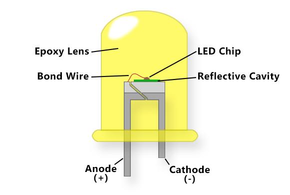
Figure 1. A diagram of an off-the-shelf round-top LED module. By Commercialledlights.com
A similar approach was used to test the sensitivity of sensor modules for this study. Several sensor types were tested such as
photoresistors, photodiodes, and phototransistors. Viability was ranked based on the sensor’s ability to detect changes in light levels. To record this, each sensor was wired to an Arduino with a recommended sample code. A white LED at a constant voltage and amperage across all tests was then used to test each sensor, while the analog read values were displayed on a computer wired to the Arduino using a simple serial print code. The LED was toggled on and off both manually and using software while the sensor distance between the sensor and the LED gradually became larger. The fluctuations in values were recorded at intervals of 1 foot. The experiment was halted when the sensor could no longer distinguish between ambient light and light emitted from the LED. The accuracy of each sensor was also recorded, namely the fluctuations in output values while in ambient light.


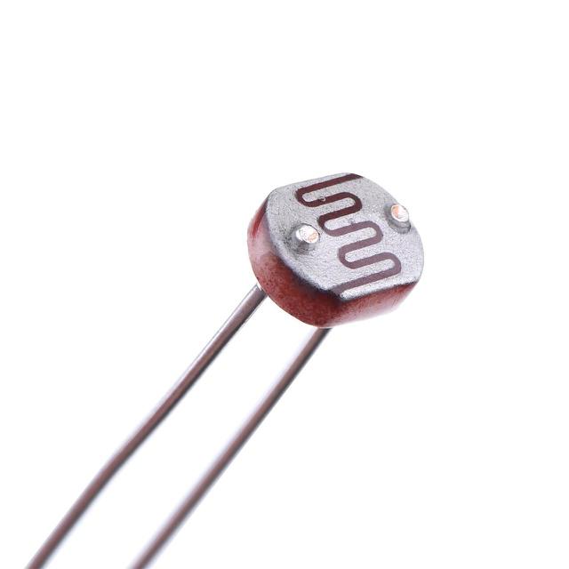
Figure 2. (left to right) A phototransistor SMD (Surface Mount Device), a photodiode, and a photoresistor.
Results (Part 1)
Following the tests of each LED and LED module, it was found that LED modules from low-cost flashlights proved more effective at producing a focused beam of light than standalone LEDs. While standalone round-top LEDs are designed to produce a radiant beam of light, many of the small flashlights include a metallic reflector to focus the beam. While the effective light distance of the round-top modules averaged 3 feet at their nominal voltage levels, the LED modules averaged 10 feet, the length of
our test tank. By slightly overvolting the 4.5-volt modules up to 5 volts, we were able to increase the brightness without overheating the modules.
After testing each sensor type, it was found that the surface-mount ambient light sensor modules from Adafruit were the most effective at detecting changes in light levels. These modules utilize a phototransistor in a surface mount device (SMD) manufactured by Everlight. While photoresistors were the cheapest option, their sensitivity range was too low for our application. Phototransistors and photodiodes provide an output voltage linearly correlated to the light intensity while photoresistors typically do not. While photodiodes are known for being faster than phototransistors, they are also less sensitive which is more important for this application. In ambient light, the Adafruit light sensor modules were able to detect a change in light at up to 8 feet away. Additionally, at $2.50 per module, the cost would not be an issue for accessibility. The final circuit was assembled by plugging the module's power and ground pin into the Arduino’s 5-volt and ground pin respectively and the signal pin to an analog input pin on the Arduino.
Part 2: light housings and waterproofing
Once the optimal LED module and sensor were chosen, each component required a reproducible and durable waterproof housing. The initial waterproof enclosure design for the sensor consisted of a bottle cap and clear plastic from the package of a small electronic component. Three holes were drilled in the cap for the sensor’s pins to slide into. Next, wires were soldered onto the sensor’s pins from outside the bottle cap, however, after this attempt, the wires were soldered onto the module prior to inserting the sensor in the housing. Following this step, a clear plastic circle was cut from the packaging material and hot glued into place, creating the final enclosure. Hot glue was applied both prior to

combining the cap and plastic and after they were mated. This enclosure was tested in the Sea Grant Lab’s test tank at varying depths of up to three feet. However, it was quickly discovered that this design had many faults, notably with the adhesion of hot glue to the plastic cover unpredictability of a hot glue seal. While a second successful due to the scoring of the edges of the plastic cover for better glue adhesion, the design requirements for ease of reproduction and was
The initial design for a waterproof LED module utilized a top LED with heat shrink tubing and hot glue around the wires and base of the LED to adequately waterproof it. This design yielded positive results and did not leak because it d air gaps. This design was also simple to produce and very compact, however, following the decision to use larger and not
abandoned for a more standardized enclosure. Additionally, due to ion index of the LEDs themselves in water, they needed a secondary clear cover to focus the light necessitating the need for shelf O-

housing body (without its top plate)
loosening the 6 retaining bolts. To ensure this design would be easily scalable and simple to manufacture, it was designed using Onshape, a computer-aided design (CAD) program. The design consists of a hollow cylinder with a hexagonal face on one end with 6 bolt holes as well as 3 small holes in the bottom for wires. 6 bolt holes were chosen for an optimal blend of strength and ease of assembly, however, if this design were to be made significantly larger, additional bolts would be necessary. On the hexagonal face, there is a round groove for an O-ring made 0.5 millimeters larger than the ring’s diameter to ensure a tight fit. The depth of the grove is roughly half of the Oring’s thickness to allow for compression of the O-ring for better sealing. Chamfers were used throughout the design to reinforce 270° overhangs and smooth edges. A 3-millimeter wall thickness was used throughout the design to ensure structural integrity at depth. Due to the design being computer-modeled and easily scalable, it can be quickly modified to fit various sensor and light modules. The main enclosure body was 3D printed using a Formlabs resin printer and post-processed following the correct procedure to ensure it was leakproof and structurally sound. Small
tweaks were made after printing such as drilling the wire holes at the bottom and sanding off burrs from excess support material. The design also requires a cover that functions as the viewing window for the light or sensor inside and compresses the O seal the unit. This cover was also modeled in Onshape and features the same geometry as the hexagonal face of the enclosure. However, instead of extruding the model, it was left as a sketch for laser cutting. The cover was laser cut out of ⅛ inch acrylic to meet these specifications. While polycarbonate (a similar polymer to acrylic) is 30 times stronger than acrylic, our modules would be exposed to relatively low forces, negating the need for polycarbonate. Additionally, while polycarbonate has 88 transmittance, acrylic boasts 92% light transmittance (A&C Plastics, 2024). While this difference is minute, it can be the difference between an extra few inches of range. the wire entry points marine utilized. After assembly, the design was tested extensively in the lab’s test tank. To ensure repeatability multiple enclosures were manufactured and tested.
After rigorous testing, this modular design proved reliable and could be scaled using CAD with minimal effort. However, after over 5 water trials and 3 prototype units, one weak point was found in one module where the wires exit. While the marine grade Loctite epoxy has exceptional strength, it dries very rigidly and does not allow for wires to bend or be manipulated close to the module. Because of this, cracks developed in the epoxy where wires could bend. This caused water to enter the module,
necessitating a new type of waterproof sealant. In response, we chose a one-part marine-grade silicone-based sealant with elastic properties once dry. This allowed wires to bend without compromising the seal. After this change was made, additional water trials were conducted with positive results. The leaks were mitigated entirely and we were able to proceed to the next step. To properly mount the sensors to the SeaPerch II and the wall of the test pool, PLA 3D-printed mounts were used. Because of PLA’s accessibility and relatively high strength, the material was selected. Additionally, it can be printed using off-the-shelf FDM (filament deposition modeling) 3D Printers because water entry due to layer adhesion would not be a problem as these mounts do not house waterproof components. The mounts were designed with 2 holes on the end that align with 2 of the 6 holes on each module. This choice was made so the mounts could easily bolt up to existing sensor modules without redesigning them to have a dedicated mounting point. The face of each mount has a thickness of 2.2 millimeters to mitigate the need for longer bolts on each sensor/LED module. On the same plane, each mount has a circular cutout designed with tolerances so they could easily snap onto ½” schedule 40 PVC pipes. The choice to make the circular cutout on the same plane as the sensor mount was made to simplify 3D printing time and ease of printing as no support materials are necessary. The circular cutouts measure 210 degrees of a full circle and are designed to flex when snapping onto a pipe. Additionally, the diameter of the circular cutout in each mount measures 2mm less than the diameter of the PVC pipe for a tight fit. The thickness
of the claws that grip the pipe is 3mm allowing them to flex when being snapped onto a pipe.
Initially, the height of the claws that gripped the PVC pipe was far too short making the claws weak and subject to plastic deformation. They also did not grip the pipe well and would slide around. To fix this, the height was increased to 5 millimeters, allowing for less flexibility and slippage on the PVC pipe.

sensor units were chosen to be mounted on the SeaPerch 2 while the tank was to be fitted with LED modules. Due to the tank’s square shape, it was chosen to mount 4 Light modules, one on each corner of the tank for communication with the SeaPerch. Due to
the tank being used for several other projects, the lighting solution would have to be temporary and removable while having a relatively simple set-up process. PVC pipe mounts were chosen for their adaptability and the modules were already configured to mount to PVC. A modular mount that slides onto the rails of the tank was chosen, with all aspects being adjustable. The depth of the LED module as well as its angle could be modified by adjusting and adding longer or shorter pipes to the mount.

As previously mentioned, an Arduino Uno microcontroller was chosen to control both the robot and the light system attached to the tank. One Arduino would be allocated for the SeaPerch while another would be used for control of the tank lights. For higher power capabilities, an Arduino-branded 4-channel relay shield was chosen, simplifying the development process. This shield slides over the Arduino and contains 4 solid-state relays which can handle more current than the Arduino’s digital output pins. The 5-volt power pin of the Arduino was wired to the output of the 4 relays which were switched on the input side using the Arduino’s digital output pins. This way high-speed switching of each LED module could occur without compromising their brightness.
light module connected
To easily wire each LED module to the relay-equipped Arduino, 2-pin quick-connect connectors were utilized. Chosen were off-the-shelf JST connectors commonly found in remotecontrolled vehicles. The positive wire of each connector was wired into their respective relay modules while the negative wires were spliced together and connected via a single wire to the Arduino’s ground pin.

equipped Arduino for light control
To properly wire the light modules, each module was first placed in its corresponding corner of the test tank while the control Arduino was placed in the center of the most accessible side of the tank. Wires were soldered to the positive and negative wires coming from each LED module and routed around the tank to the control Arduino. The wires were then cut at length and spliced to the male JST connectors. Following this step, each wire was labeled with tape, both on the LED and Arduino side with corresponding numbers 1 through 4.
To avoid tangling wires and for ease of routing, 3D-printed wire organizers were utilized. These organizers were designed using Onshape and feature a print-in-place design with a rectangular, rounded bottom with a hook on top as pictured in figure 8. The rounded bottom is designed to slot and twist in place into the 80-20 aluminum extrusions used for the rails of the tank. The bottoms of the initial iterations were either too large or small and did not twist and lock as intended into the 80-20 aluminum extrusions. Once the design was finalized, over 20 clips were
Figure 8. A 3Dprinted wire organizer

rings for adequate waterproofing. The same techniques used for the assembly of the smaller modules were utilized for the sensor array. Once assembled, a separate PLA divider was designed to bolt on top of the module. This divider ensures each sensor only receives light when pointed in its direction which is necessary for light following. Similar dividers have been utilized for sun-tracking solar panels, as well as heat-seeking missiles such as the early AIM-9s. To wire the module, each of the sensors’ ground pins was spliced to a common ground wire as well as the 5-volt input pins to
a common 5-volt wire. This left the array with 6 wires, a ground, 5 volt, and 4 sensor wires for each light sensor.
With a completed sensor array, a new SeaPerch 2 design was devised to house it. Like other SeaPerch 2 designs, it features a PVC pipe frame and pylons to fit two thrust motors and a vertical translation motor along with a waterproof control box to house the Arduino and battery. 4 input pins from the Arduino were additionally wired and soldered to each of the four sensor modules in the array. Following this step, the hardware was complete and code could now be developed and tested.

Figure 9. The completed quad sensor array with a PLA divider and PVC pipe mount

Figure 10. The completed Seaperch 2 frame with the quad sensor array and supporting electronics
Part 3 (code)
There were two main objectives for the SeaPerch that Nathan and I aimed for. One was to get the SeaPerch to follow a light source, and the second was to relay commands to the SeaPerch using light. While I focused on the hardware aspect of the project, Nathan focused on the software. For light following, a feedback loop was utilized with all four sensors in the array. If the sensors on the left detected more light than the sensors on the right, the right motor would ramp up to turn the SeaPerch toward the light source and vice versa. Similarly, the top and bottom sensors’
input values would control the depth of the SeaPerch using the vertical translation motor.
To relay commands to the SeaPerch, a modified form of Morse code was used, with differing series of long and short flashes corresponding to a letter. With this system, we were able to relay information up to 10 feet away. The end goal of this system was to relay commands to the SeaPerch and have different commands trigger various functions of the vehicle. While there was not enough time to add these functions, the communication system proved viable.
Results (for part 3):
After extensive testing, the light-based communication system proved effective for both light tracking and relaying information. The Morse code system we developed was able to transmit accurate data up to 10 feet away through water with near zero latency due to light’s high-speed transmission. The components used in our design proved reliable during test runs and the waterproof housings did not leak. Despite this, one issue arose in the waterproofing of the wiring for our sensor array. Due to slight variations in heat-shrink tubing and some human error, water was able to enter our wiring causing erroneous sensor readings. This issue was later diagnosed and fixed with additional sealant and heat-shrink tubing.
Discussion
The basis of this project was to use SeaPerch 2, an educational platform for high school students, to design an accessible and easy-to-assemble communication system. Our system uses off-the-shelf components and is easy to program while being cost-effective for high schools. After extensive work, we have proven that light-based communication is viable for underwater data transmission. Due to the accessibility of our system, it has practical applications for school clubs and even the international SeaPerch competition organization. With continued development, our system could be used for SeaPerch to SeaPerch communication and data transmission. By increasing the number of light sensors on a SeaPerch in addition to fitting the craft with LED modules, this is feasible and will open many new opportunities for SeaPerch coordination. However, due to the nature of light and the unpredictability of currents and water quality in the open ocean, this system remains most viable for short distances and controlled environments such as pools. While lightbased communication offers a promising alternative to more complex and expensive radio frequency (RF) or acoustic communication systems, the behavior of light underwater is significantly influenced by factors such as water turbidity, depth, and angle of transmission. These factors contribute to attenuation, scattering, and refraction, which can reduce the effectiveness of the system over longer distances. Despite these limitations, this system’s modular design could be upgraded with more expensive light and sensor modules to improve the range for applications outside of SeaPerch 2. The addition of optical fiber or laser technology could also provide better control over the light transmission, ensuring that the signal is less prone to interference from environmental factors. While the system currently stands as an accessible demonstration of short-range light communication, future research in unpredictable waters, and development towards
light transmitting and receiving devices could be conducted to address the challenges posed by long-range communication underwater.
Bibliography:
A&C Plastics Editorial Team. (2025). Polycarbonate Material vs. Acrylic Material. A&C Plastics Inc.
https://www.acplasticsinc.com/informationcenter/r/acrylic-vspolycarbonate
Bennett, A., & Brancazio, D. (2024, June 12). SeaPerch II. MIT Sea Grant. https://seagrant.mit.edu/seaperch2/
Chiang, John. Y, Chen, Ying Ching, Chen, Yung Fu. (2011, August). Underwater Image Enhancement: Using Wavelength Compensation and Image Dehazing (WCID). ResearchGate.net. https://www.researchgate.net/publication/220785640_Underwater_ Image_Enhancement_Using_Wavelength_Compensation_and_Ima ge_Dehazing_WCID
Commercial LED Lights Editorial Team. (2022). LED Technology. Detroit Trading and Sourcing.
https://commercialledlights.com/blog/lighting-articles/ledtechnology/
Gamma Editorial Team. (2023, May 15). Light transmission in the ocean and other bodies of water. Gamma Scientific. https://gamma-sci.com/2021/08/16/light-transmission-in-theocean-and-other-bodies-ofwater/?srsltid=AfmBOorIym4W_T6qAl7tyg7nElhA3Xzhrzt6IijK Mf6OxzYnRrpLA2ZO#
Sealing & Shielding Team. (2016, September 14). Sealing Fundamentals | Face Seal. Blog.parker.com. https://blog.parker.com/site/usa/en-US/details-home-page/sealingfundamentals-face-seal-us
Shen, S. C., Sathe, P. V., Chang, P. C. Y., Zheng, G. F., Okamoto, T., Ingle, J. D. J., Chang, C. H., & Orlov, M. Y. (2012, November 16). Design and analysis of a high-intensity LED lighting module for underwater illumination. Applied Ocean Research. https://www.sciencedirect.com/science/article/abs/pii/S014111871 2000843