Nathan
Senior Thesis | 2025

Development of a New Method for Tetherless Underwater Communication Using COTS Parts
By Nathan Wu
Abstract
Educational programs like the SeaPerch Program, initially developed three decades ago by the Massachusetts Institute of Technology (MIT) and the Office of Naval Research, have proven effective in introducing students to robotics and engineering through an affordable curriculum [1]. These initiatives play a vital role in sparking students' interest in robotics and equipping them for advanced studies and careers in STEM fields [2]. As STEM disciplines continue to expand rapidly in the 21st century, it is crucial to evolve such programs to ensure students acquire the skills needed for future jobs and research [3]. The SeaPerch Program, created by the MIT Sea Grant Lab in the 1990s, offers a hands-on, project-based learning experience. Additionally, design challenge competitions encourage creative problem-solving as students enhance their basic SeaPerch models to meet specific challenges [4]. To integrate both emerging and established technologies, the MIT Sea Grant Lab is developing SeaPerch II, a new take on the original program. The SeaPerch II aims to bridge the gap between traditional and cutting-edge technologies, offering a more accessible and affordable way for young students to explore
science and technology. Wireless underwater communication has been a popular topic for research, and this paper builds on the SeaPerch II program by providing a cost-effective method to introduce students to it. After discussing various methods of underwater communication, including acoustic, radio, and optical communication and going over the benefits and downsides of each method, this paper provides a method to communicate optically with the SeaPerch without the use of a tether using cheap, commercial off-the-shelf (COTS) products such as Arduinos and LEDs.
Introduction
Keeping education caught up to recent technological advancements and new methods of research is crucial for students to engage in their own research. However, schools can only teach so much, and the foundation of sciences is just as important as the current innovations. Therefore, extracurricular programs are helpful for alleviating the burden of teaching students about modern technology. Programs such as SeaPerch, founded in the 1990s, strive to “reduce traditional barriers to participation in robotics programs and promote [...] inquiry-based learning with real-world applications” [5], and use robotics kits and online guides to help students build their own underwater remotely operated vehicle (ROV). And while the program has been adopted by RoboNation into a high school competition where students are able to customize the SeaPerch robot to complete various challenges, it still has been 30 years since its creation, and it is necessary to update these technologies beyond the scope of what the students are familiar with. In order to keep up with newer technologies, the SeaPerch II project was recently introduced to have various modules that taught students about them. Some
modules such as hydraulic grippers, depth sensors, and IR sensors have documentation on their website and visual representation as seen on figure 1 so that students can easily replicate them and learn about soft robotics and Arduino sensors, as well as their applications in the real world [6].

1: Hydraulic Gripper and Depth Sensor on a SeaPerch II [6]
The development of new modules is still continuing, and the research on tetherless communication explores a new method of transmitting information to the SeaPerch, which brings it closer to becoming an autonomous underwater vehicle (AUV).
There are three main methods for underwater communications, which are radio, acoustics, and optics. Radio control (RC) at first seems to be a very appealing form of communication, considering how it is used for satellites, phones,
Figure
radios, and TVs. However, once underwater, the range is greatly lowered and it is hard to communicate in high or even ultra-high frequencies, making it difficult to communicate complicated information in a reasonable timeframe. This is due to seawater being highly conductive, which affects the propagation of electromagnetic waves [7]. Additionally, while lower frequencies are reliable enough to work for greater distances, the equipment for underwater radio communication is undesirable for this study as it is expensive and very large, which requires high power. There is also a method to increase the range by adding multiple receivers underwater which pass on the frequencies, but that only works in shallow water and would increase costs [7]. This directly contradicts SeaPerch’s mission of providing accessible learning for everyone and is not very replicable for students, and so will not be used for research.
Acoustics do not suffer the range deficiency that RC does, and are commonly used for underwater communications. Some challenges of acoustic communication are the Doppler Effect & multipath propagation, but computational models have helped circumvent that in recent years [7]. While it might suffer from scattering when it hits an object underwater and could be misinterpreted if the code is inaccurate, it is still a very popular method that is worth considering. However, the downsides of acoustics are much like RC’s, as most hydrophones (microphones that are specialized for underwater scenarios) are out of the budget of students or don’t read accurately enough to communicate efficiently with a SeaPerch, which as stated before contradicts SeaPerch’s mission.
The final viable method is optics. While optics lacks the range that RC and acoustics can achieve, it is certainly much cheaper and there exist methods to circumvent the range
deficiency. Additionally, it can send messages at a faster rate than RC and is not affected by the Doppler Effect, though communication may still be blocked by objects in its way. Due to the advantages that optical communications have, it is slowly becoming adopted by various military fields, AUV drivers and marine fields [7]. It is also much cheaper than both of the above methods, as while a good hydrophone might cost upwards of $500, an LED that can cover tens of meters underwater only ranges from $20-30. Because of the various advantages and cost, optical communication has been chosen to be further researched for the purpose of this study.
This research will provide a new method to control the SeaPerch, which can potentially solve problems like tethers getting tangled together and provide a simpler control mechanism. It also has applications outside of competitions, such as boat control and long distance communication with underwater cameras, offering a cheap, radioless solution to underwater communication.
Methods
In order to find what is the most effective form of optical communication, there are a couple of factors to consider: the wavelength of the light, how strong the light is, and accessibility (the cost and how easy it is to find). Wavelengths are important because it directly affects how much the light is absorbed, which influences how far the light can travel through the water before becoming unable to be detected. As shown in figure 2, the wavelength with the lowest “relative absorption” is around 500 nm, which makes it ideal for underwater optical communication.
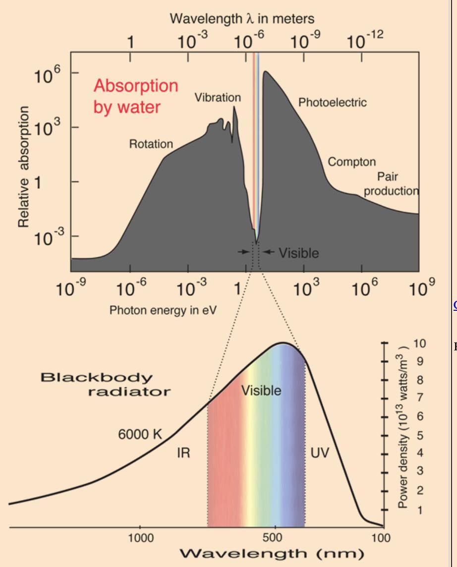
Figure 2: The Absorption Spectrum of Water [8]
The light at a wavelength around 500 nm is close to a dark blue, which makes sense since the ocean is also that color, signifying that it is not absorbed as much compared to other colors. However, the lab where the module was being tested in had water in the pool closer to a more blue-green tint (likely due to the chlorine added to the pool), so it was believed that a blue-green light would be best for this body of water specifically, though it would still be worth it to test a dark-blue LED. When buying the LEDs, it was easy to find an LED that had a blue wavelength and not one that was made blue with the stained glass that surrounds it. Blue-green LEDs on Amazon are almost all made up of either a blue and green LED, or using stained glass, which would dim the LED, making it not worth it to use. Therefore, the LED that would be used was the blue LED that was fairly bright and easy to find.

Figure 3: Dark Blue LED
When testing the blue LED outside of water, it could communicate with the sensors over 5 meters away (which was determined by if the sensors could detect a noticeable change in light level when the LED was turned on). But when it was placed underwater, the range decreased drastically, and could only go to
around 2-3 meters. In order to understand why this happens, it is essential first to examine the fundamental principles of how LEDs and light work. The LED chip inside the glass or plastic housing first emits light that goes in all directions inside the plastic, until it reaches the part where it transitions from plastic to air. As seen in figure 4, because of Snell’s law, when light goes from a higher index of refraction (in this case, plastic) into a lower index (air), the light will bend away from the normal of the face. So because there is a difference in the index, the LED’s special shape and epoxy lens can concentrate all the light that was originally scattered, making the light travel more distance. However, this does not apply underwater, since water and plastic have a similar index of refraction, and the light just disperses however it wants to.
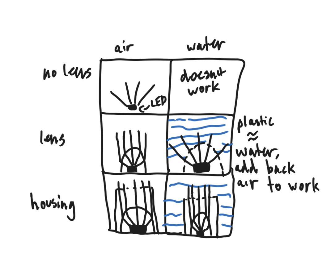
In order to counteract this, waterproof housing as seen in figure 5 was created to add back the layer of air that helped concentrate the light.
Figure 4: Effect of water on concentrating LED lenses
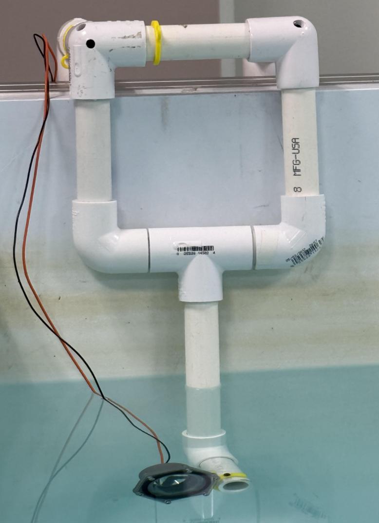
Figure 5: Housings for the LEDs
By using a resin printer and o-rings, a waterproof housing was created that brought the range back up to around 4 meters underwater. It is important to note that a Polylactic Acid (PLA) printer will not work, since PLA filament is not waterproof, and that a resin printer is needed. And while a resin printer is not as accessible as a normal PLA printer, this is just one of the many ways that a waterproof LED housing could be created.
Lasers were also tested to see if they would be more viable underwater due to their high power. However, it needed the sensor to be almost directly looking at the sensor to actually work, which is too precise for the SeaPerch’s purposes. It was also tested to see if different lenses could be used to either concentrate the LED or disperse the laser, but the LED either became too precise, and the laser became just as dim as a normal LED when the light it emitted was dispersed. Therefore, housings for LEDs were found to be the best solution.
Alongside a blue LED, bike light LEDs were also tested to evaluate if they would be effective, as even though their wavelength is absorbed more, its greater luminosity could let it communicate at greater distances.
For the sensors to receive the signal from the light, Adafruit ALS-PT19 analog light sensors that have phototransistors were used. Other sensors, including photodiodes and photoresistors were tested, but they were found to be less effective than the analog light sensors. Housings for the sensors were also created using the same methods mentioned above.
Code for Communicating with the Robot
The code for communicating with the robot from land went through three different iterations, and they each have their own benefits, ranging from just sheer simplicity and speed of transmission to flexibility and large margin for error. It also activates multiple autonomous modes, including a homing system and depth setting which will be discussed below.
The first iteration of code included just four commands, and was a proof of concept that it would work underwater. The way this worked was by sending either a long blink (hold) or short blink, and having that coded as a 1 or a 0, respectively. Based on the two binary inputs that the light sends, the Arduino then compares it to the four possible combinations, and then correlates that to a command. This was mostly to get the timings correct so the sensor is reading at an appropriate speed to correctly interpret what the LED is sending, and in order for humans to still be able to see what the light was sending, it was purposely made to be slower
than needed for debugging purposes. While this code could transmit commands quickly, it had too few commands that it could send and was not as flexible as desired. While the number of commands the SeaPerch knew could be increased exponentially by extending the length of inputs it could take to 3 or 4 (having now 8 or 16 commands instead of 4), it this system would be too inflexible to actually use, and it would be too hard for users to memorize all the commands, especially if it gets up to commands that take 5 inputs.
Instead, the second iteration of code took inspiration from morse code, and developed its own version that used a binary input of length 5 (leading to 2^5 different commands/inputs), and corresponded that to a letter in the alphabet (for example, the letter “e” would be 00000, or 5 blinks). Since this code would still leave 6 blank inputs, this left space for things like numbers and other autonomous commands. Instead of adding numbers, however, autonomous commands took priority since there was not enough space to add all the numbers, and it would be a better use to find a different way to represent numbers through the code, such as through a string of letters. This also left space for future commands to be added that would be specific to the tasks the SeaPerch would be performing.
The 3 autonomous commands were: increasing depth, lowering depth, and a heading home program. The two depth changing commands relied on a pressure sensor attached to the center of the SeaPerch as seen in figure 6, which was inside of a balloon filled with enough air so that it could feel the change in depth whilst being safe underwater.

When the SeaPerch reads an increasing/decreasing depth command, the SeaPerch would change its resting height by 5 cm (which is configurable in the code) each time, and can not raise higher than 0 since that should be the surface level.
The head home program, when activated, would keep the light that is sending commands on to act as a beacon for the SeaPerch to head to. That way, the SeaPerch would be able to keep track of its orientation in respect to the light and head forward until it passes a threshold brightness, after which it stops moving. In order to achieve this, inspiration came from the AIM-9’s missile guidance mechanism, which involved 2 infrared trackers [9].
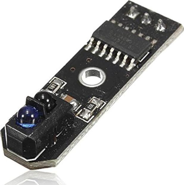
7: Modern Infrared Tracker [10]
Most infrared trackers contain two sensors, which are blocked off from each other to avoid the signal bleeding to one another, and compares the two inputs to see which way it should move to directly face the infrared, or when both signals are approximately equal. The reasoning for the two infrared trackers is for the missile to see both left and right differences, as well as up and down differences. The SeaPerch’s sensor is similar to this, and a housing was created for four sensors in a 2x2 formation and a separate divider was printed out to avoid bleeding as seen in figure 8.
Figure
Figure 8: SeaPerch’s Light Sensor Housing
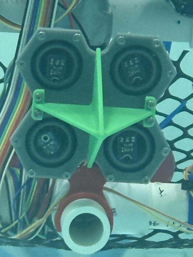
The code reads from three of the sensors (bottom left & right, and top right), comparing them constantly to see if the difference is greater than a pre-set threshold. If it is, the SeaPerch will then turn on a motor at a constant speed that will direct it towards the side with stronger light, until the differences are fairly equivalent. Once they are, the motors would both be powered at equal speed. The up/down motor would not have to activate, as the SeaPerch was made to have a buoyancy where it would not sink or float once underwater. The reason why four sensors were used when three could suffice was so that if a separate command was sent, the fourth sensor could read it and change the command.
While some optimizations were made to make the code quicker (like the most frequently used letter ‘e’ being 5 blinks in a row), the time it took for commands to send was still slower than desired, and was overall less optimal for communication with robots. Even though it was the most flexible form of communication, the extra complexity and length of each message made it undesirable, and a separate code was created. However,
this code could still be used for human-to-human or robot-tohuman communication, though it would still be very slow.
The third iteration of the code focused on sending commands to each motor, telling it the speed and which direction to go in. This was done by designating each motor to a set of three letters corresponding to forward, reverse, and stop. Specifically, the right motor would have ABC, left has DEF, and the up/down motor has GHI. Through this, everything can be controlled independently. Along with that, the speeds of the motors could also be set, ranging from 0 to 255. A sample command would look like this: ADG<150,50>. This would command the SeaPerch to go forward and up, and the first number (150) corresponds to the left/right motors and the second number (50) assigns the speed for the up/down motor. Since there are 9 letters, 3 special characters, and 10 numbers (22 in total), the same length five binary input would have to be used, and just have a lot of extra commands left over. While this would be fine, the speed of each message would still take too long to send in a respectable time. Since each command is so similar, there are many ways to shorten the message, starting with the letters. Since the motors were always referred to in the same order, there is no technical difference between A, D, and G, or B, E, and H, or C, F, and I. Because of this, the letters could all have the same binary output, which reduced the number of inputs from length of 4 to 2 (with 00 relating to ADG, 01 to BEH, 10 to CFI, and 11 for a separate command called “double long”, which will be discussed later). Because there is always a “<” after the letters, there is no need to have a unique input for it. The numbers can be represented with a sequence of length 4, with common numbers such as 1, 0, and 5 having the most blinks. Additionally, inputs for a comma and “>” symbol were added to separate the two speeds and end the command, respectively.
The “double long” command is completely different from the motor commands, and is for the autonomous commands. While the SeaPerch is looking for inputs for the motors, it is also looking for if it ever receives the two holds, in which case it will ignore the rest of the motor commands and instead watch for what other command it should perform. Because there are three autonomous commands, the command to determine which one will have to be expanded by 2 more inputs. Because there are only 3 commands, however, one command can just be of length 3. The final inputs for the commands were: 1101 to increase the depth, 1100 to decrease it, and 111 activates the head home command. The way this iteration incorporated the depth keeping was by checking the speed of the up/down motor, and if it was greater than a certain number (in this case, 10), the depth keeping would be turned off for some time and the SeaPerch would be able to freely move wherever it wants.
Because the sensors can only see in one direction, the SeaPerch might not always see the command unless it is sent perfectly, and so multiple lights were added on different corners of the pool to ensure that it would see at least one light at all times. In order to control all the lights at the same time, the Arduino 4 Relays Shield was used, so they can be controlled by one Arduino connected to a computer. The computer uses the Arduino IDE, through which it can change which light it is controlling and send commands through the serial monitor. During testing, it was found that sometimes the light wouldn’t reach where the SeaPerch was looking. While installing more lights at different positions could help, it is not useful on a bigger scale, since that would require more and more lights. Instead, a separate command was given to the SeaPerch, where if it did not receive a command for around 15 seconds, it would start spinning around until it found a spot where
the light level was greater than that around it, which should theoretically be the light at shore, and then stop there for commands.
Results
Using the LEDs taken from bike lights and a housing that can properly concentrate the photons, light can reach over 10 meters underwater, which is enough for the scope of this research. While some other LEDs did show promise such as one with a blue wavelength, the strength of the bike light made it so that it was the most effective, even though it does not penetrate water as well. The most direct improvement to the light source was the creation of housings, which as stated before in the methods helps light concentrate and therefore become more potent, over the wavelength of the light.
Additionally, through the three versions of code, it was found that a control system that denotes each of the three motors is the most efficient way to communicate with the robot. The first and fastest version was too simple to control a robot. While the morse code system could send much more complex commands, it was too extra and had too much complexity, leading to slower command send times. The third and final method which combines both approaches is both quick enough to give commands in a timely manner and has room for all the desired commands and more if necessary in the future. While a morse code approach would work for human-to-human interactions, there are many other methods to communicate faster with a computer, such as the motor-denoting system used here. The proposed code also has space for expansion, as it establishes a simple modular system where more motors, commands, and parameters can easily be
added through the different input sections. While sometimes the robot interprets commands incorrectly, it is designed to only do the command for a short time, so incorrect inputs don’t severely interrupt the robot’s movement, and rather consistent commands are rewarded. The model is also fairly sensitive, as the ambient light level is ~50 lx in the pool, and is at ~200 lx when the light is shone, which is far greater than the threshold difference of 12, meaning that it can send commands at greater distances as well with no difficulty.
Conclusion and Future Work
The goal of the SeaPerch program has always been making marine robotics simple and accessible for new and younger audiences. This new communication module has been able to maintain the low cost and the level of complexity, making SeaPerch II even more friendly to beginner audiences.
Through using Arduino and making the code open-sourced online, students can easily learn and improve it as they see fit, and even add on through using different shields that Arduino provides. This research proves that optics is one way to achieve tetherless communication with the SeaPerch. However, other methods such as radio and acoustics could be tested, as this experiment was mostly focused on achieving communication while minimizing costs. In the future, along with just optimizing the code through potentially removing unused numbers like 3, 7, 8 and only keeping more popular ones, the commands should also be sent through a separate controller, so it would be faster and easier for everyone to control the robot. Additionally, because the SeaPerch is used in competitions, this module should be made to work with multiple robots. In order to control each craft individually without the
commands being read from other robots, there would need to be some sort of way to identify that this command is for a specific robot. This could be achieved through the use of different wavelengths, which could be easier for radio control, or another way is through giving each robot its own ID. Finally, a method for tracking the movement of the SeaPerch through simulations and the data the SeaPerch II collects through something, similar to the AdvantageScope tool used in the FIRST Robotics Competition, could prove useful, as then students can playback how it performed and what to improve on in the future more easily [11]. Overall, this work sets the foundation for a tetherless communication system for the SeaPerch II and leaves room for many possible improvements.
References
[1]
S. Nelson, K. Cooper, and V. Djapic, “SeaPerch: How a start-up hands-on robotics activity grew into a national program,” IEEE, p. 1, 2015, Accessed: Jan. 01, 2025. [Online]. Available: doi: 10.1109/OCEANS-Genova.2015.7271419
[2]
S. Giver, “The Sea Perch Challenge Generating Interest in Marine Engineering, Ocean Engineering and Naval Architecture through hands-on activities,” 2008.
[3]
“Charting a Course for Success: America’s Strategy for STEM Education,” Committee on STEM Education of the National Science and Technology Council, pp. 1–48, Dec. 2018, Accessed: Jan. 01, 2025. [Online]. Available: ERIC Database File: ED590474
[4]
S. Wang, S. Andrei, O. Urbina, and D. A. Sisk, “Introducing STEM to 7 th Grade Girls using SeaPerch and Scratch,” in 2020 IEEE Frontiers in Education Conference (FIE), IEEE, Oct. 2020, pp. 1–8. doi: 10.1109/FIE44824.2020.9273984.
[5]
“About SeaPerch,” SeaPerch.org.
[6]
“SeaPerch II - MIT Sea Grant,” MIT Sea Grant.
[7]
S. Kumar and C. Vats, “Underwater Communication: A Detailed Review,” Workshop on Computer Networks & Communications, May 2021, [Online]. Available: https://www.researchgate.net/publication/352712873
[8]
R. Nave, “Transparency of Water in the Visible Range,” Gsu.edu. Accessed: Jan. 01, 2025. [Online]. Available: http://hyperphysics.phy-astr.gsu.edu/hbase/Chemical/watabs.html
[9]
C. Jackson, “Missile Guidance System Patent,” Feb. 16, 1965
[10]
“ILS. - 5V Infrared Line Track Tracking Tracker Sensor Module for Arduino,” Amazon. Accessed: Jan. 01, 2025. [Online]. Available: https://www.amazon.com/ILS-Infrared-TrackingTracker-Arduino/dp/B07ZP1SCXY
[11]
“AdvantageScope,” wpilib.org. Accessed: Jan. 01, 2025. [Online]. Available: https://docs.wpilib.org/en/stable/docs/software/dashboards/advanta gescope.html