Bradbury Group Fitting Instructions


SURVEYING
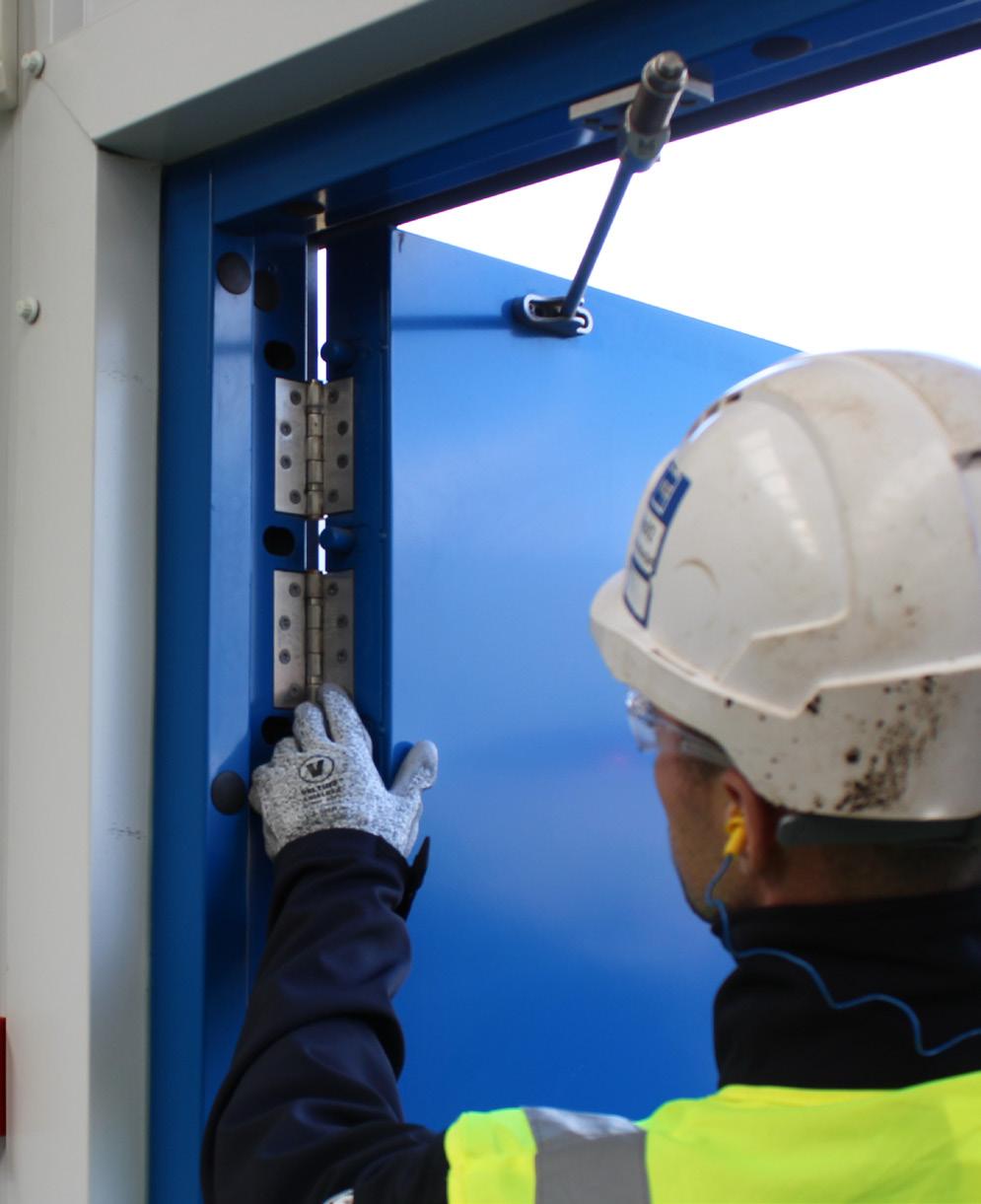
Accurate surveying is important for correct installation. Please take measurements from the top, middle and bottom of the width and use the smallest measurement. Repeat for the height.
If providing Bradbury Group with the structural opening measurements, we will reduce the overall manufactured frame size by 10mm in the width and 5mm in the height, this is to allow tolerance for the installation.
It is the client’s responsibility to ensure the opening is fire and security rated, square, clean and accessible, prior to installation.
PRE-INSTALLATION CHECKS
• Masonry drill bits and standard drill bits
Pencil or marker pen
• Spirit level
Measuring tape
Fixings to comply with the minimum fixing standards
• Tools to install fixings, i.e. cordless/corded drills
• Mastic or similar filler
• Open supplied package and check contents against delivery note
• Ensure the area is clear of all obstructions Make sure the structural opening is solid and can achieve the fire and security rating of the door to be installed Check that the door frame supplied will fit into the opening
Check that it is safe to drill around the opening
M2M Fitting Instructions 05-04GB, 02-24 2
EQUIPMENT & TOOLS REQUIRED
02 - Surveying - Equipemnt & Tools Required - Pre Installation Checks CONTENT 07 - Silicone Teardrop Fire Seal 10 - Installation Instructions for Single Doors Without Adjusters 03 - Security Rated Doors - Fixing Options for Security Rated Doors 08 - Standard M2M+ & Capital45 CF5739 Smoke Doorset - Flood Defence Doors 11 04 - Fire Rated Doors - Internal Fire Rated Doors 12 05 - Capital45 CF5739 Smoke Doorset Clearance Gaps - External Fire Rated M2M+ - External Fire and Security Rated 09 - ClassicAL Doorset 13 - Installation Instructions for Double Doors Without Adjusters - Installation Instructions for Single Doors Without Adjusters - Installation Instructions for Double Doors Without Adjusters 14 - Mastic Seal General Guide
SECURITY RATED DOORS
When installing security rated doors, the client must be fully satisfied that the structure around the aperature is more secure or equivelant to the doorset rating.
M2M2, M2M3 and M2M4 doorsets are LPCB certified to LPS 1175 SR2, SR3 and SR4, respectively. To ensure that the installation complies with the accreditation, follow one of the minimum fixing standards below.
The minimum fixing standards (below) assume installation direct into substrate not via intermediate substrate, such as plasterboard. The perimeter of the door should be made good, using mastic or similar.
FIXING OPTIONS SECURITY RATED DOORS
M2M Fitting Instructions 05-04GB, 02-24 3
Substrate Brick, Block & Concrete Steel Door Type Min Qty Min no. of fixings per vertical edge Size, Grade & Min Bolt Diameter Min Length Min Qty Size & Grade Min Length Min Steel Thickness M2M2 (SR2) 12 6 6.3mm Self-drilling screw 16mm 12 6.3mm Self-drilling screw 16mm 3mm 12 6 M6 Grade 10.9 16mm 12 M6 Grade 10.9 16mm 3mm 8 4 M8 Grade A2-70 16mm 8 M8 Grade A2-70 16mm 3mm 8 4 M8 Grade 10.9 16mm 8 M8 Grade 10.9 16mm 3mm 20 10 Hilti HRD C1080 60-150mm 20 C10-80 50-60mm 3mm M2M3 (SR3) 20 10 M8 Grade 8.8 60-150mm 20 M8 Grade 8.8 50-60mm 3mm 20 10 M8 Grade A2-70 60-150mm 20 M8 Grade A2-70 50-60mm 3mm 20 10 M8 Grade 10.9 60-150mm 20 M8 Grade 10.9 50-60mm 3mm 24 12 Hilti HRD C10-80 60-150mm 24 C10-80 50-60mm 3mm 8 4 M10 Grade 10.9 60-150mm 8 M10 Grade 10.9 50-60mm 3mm 8 4 M10 Grade 12.9 60-150mm 8 M10 Grade 12.9 50-60mm 3mm 8 4 M10 Grade A2-70 60-150mm 8 M10 Grade A2-70 50-60mm 3mm M2M4 (SR4) 16 8 M10 Grade 10.9 60-150mm 16 M10 Grade 10.9 30mm 5mm 16 8 M10 Grade 12.9 60-150mm 16 M10 Grade 12.9 30mm 5mm 16 8 M10 Grade A2-70 60-150mm 16 M10 Grade A2-70 30mm 5mm 16 8 M12 Grade 10.9 60-150mm 16 M12 Grade 10.9 30mm 5mm 16 8 M12 Grade 12.9 60-150mm 16 M12 Grade 12.9 30mm 5mm 16 8 M12 Grade A2-70 60-150mm 16 M12 Grade A2-70 30mm 5mm
FIRE RATED DOORS
Additional requirements for fire rated doors:
• Fixings to the main structural surround should comprise of steel screws of sufficient length to penetrate the main structure by a minimum of 30mm, although 120mm is recommended (plastic plugs can only be used if fully concealed within the structural opening substrate).
• All fixings and hardware must be steel (no plastic).
• Steel screws are to be inserted at a maximum of 500mm centres.
Fixing clearing holes in the frame may be covered using steel or plastic bungs.
• Any packers or shims used during installation must be made from steel.
Gaps between the structural opening and the frame should be sealed in accordance with the fire rated sealant used as per the manufacturers specification
On M2M+FD double doors, an overlap of 18mm covering the passive door leaf (anti-pry strip) is required. The passive door on double doors must be fixed top and bottom, and the active leaf must have a centre latch, as minimum.
• Wall must be of equal rating to door otherwise door takes wall rating.
INTERNAL FIRE RATED DOORS
Additional requirements for fire rated doors:
Fixings to the main structural surround should comprise of steel screws of sufficient length to penetrate the main structure by a minimum of 30mm, although 100mm is recommended (plastic plugs can only be used if fully concealed within the structural opening substrate).
All fixings and hardware must be steel (no plastic).
Steel screws are to be inserted at a maximum of 500mm centres.
• Fixing clearing holes in the frame must be covered using steel or plastic bungs.
Any packers or shims used during installation must be made from steel.
• Gaps between the structural opening and the frame should be sealed in accordance with the fire rated sealant used as per the manufacturing specifications.
• The passive door on double doors must be fixed top and bottom, and the active leaf must have a centre latch, as minimum.
The maximum gaps allowed around a fire rated door are as follows:
For M2M+FD doors:
20, 19, 18, 17, 7, 8, 9, 10 = 7mm
1, 2, 3, 4, 5, 6 = 10mm
• 21, 22, 23, 24 = 5.5mm
• 16, 15, 14, 13, 12, 11 = 20mm
For M2M2FD, M2M3FD and M2M4FD doors:
20, 19, 18, 17, 7, 8, 9, 10 = 6mm
1, 2, 3, 4, 5, 6 = 4.2mm
• 21, 22, 23, 24 = 5.6mm
16, 15, 14, 13, 12, 11 = 20mm
M2M Fitting Instructions 05-04GB, 02-24 4
2 3 4 5 6 7 8 9 10 11 12 13 14 15 16 17 18 19 20 21 22 23 24 1
CAPITAL45 CF5739 SMOKE DOORSET CLEARANCE GAPS
* Dimension not included in calucations
* Dimension not included in calucations
EXTERNAL FIRE RATED M2M+ DOORS
The maximum authorised clearance measurements for external fire rated door are as follows:
For single leaf door:
• Upper transom = 8.5mm
On hinges side = 7.5mm
On lock side = 10mm
• At the threshold = 16mm
• Central latch bolt = 14mm
Dog bolts = 22mm
For double leaf door:
• Upper transom = 3mm
On hinges side = 3.5mm
On lock side = 3mm
• At the threshold = 11mm
• Central latch bolt = 8mm
• Dog bolts = 18mm
Maximum authorised clearance measurements with seven-point lock (HOOPLY - BRADBURY) and with additional hinge at mid height
• Upper transom = 3.5mm
On hinges side = 2mm
• On lock side = 4mm
• At the threshold = 8.7mm
EXTERNAL FIRE AND SECURITY RATED
Maximium authorised clearance measurements
Upper Rail
Minimum engagement of the median latch bolt foir single leaf
Minimum enagement of the mnedian latch bolt for double leaves
M2M Fitting Instructions 05-04GB, 02-24 5 Gap Dimension in mm at Position 1 2 3 4 5 6 7 8 9 10 11* 12* 2.9 2.9 3.2 2.6 3.3 2.8 3.3 3.8 3.6 2.6 9.8 10.0 13* 14* 15* 16* 17 18 19 20 21 22 23 24 9.8 9.3 9.8 7.8 1.8 2.8 3.3 3.9 5.8 5.5 2.4 2.2 Mean 3.3 Maximum 5.8 Minimum 1.8
3mm
6mm
On hinges side
single
2.5mm
On lock side for
leaf
double
6mm
On lock side for
leaves
4
At the threshold
mm
25.5mm
10mm
Smoke Gap Dimension in mm at Position 1 2 3 4 5 6 7 8 9 10 11* 12* 2.8 2.5 2.8 3.3 3.2 2.6 2.9 2.2 3.4 3.8 4.4 4.4 13* 14* 15* 16* 17 18 19 20 21 22 23 24 4.6 4.6 4.4 4.9 2.5 4.0 3.2 2.3 2.9 3.5 4.4 4.5 Mean 3.2 Maximum 4.5 Minimum 2.2
SILICONE TEARDROP FIRE SEAL
BEFORE INSTALLATION
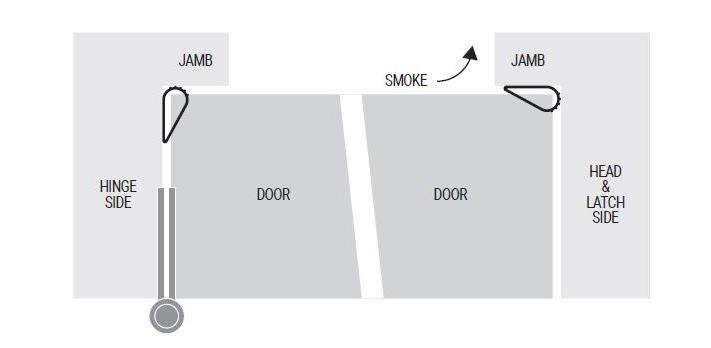
Surface of frame to be thoroughly cleaned where the gasketing is to be applied (see drawing). For cleaning the surfaces only use a clean cloth and a solvent that is compatible with the materials, such as Isopropanol (Isopropyl alcohol or IPA), Ethanol or Methanol (Methylated or surgical spirits). Make sure to check for any impediments (dust, dirt, oil, grease, etc...) or loose paint and remove them from the surface area. Surface area must be completely dry before the installation process begins.
HOW TO INSTALL
1. The first piece of gasketing should be the head piece and should be the entire length of the head. Measure and cut the gasket to size and locate properly (see drawing for location on head). Leave approximately 1.6mm between seal and door frame for clearance when compressed.
2. Remove the paper backing from the self-adhesive strip (PSA) 300 to 600 at a time and press firmly into place as you align and install the gasketing on the head. IMPORTANT - DO NOT STRETCH THE SEAL
DURING INSTALLATION
3. The strike jamb gasketing should be installed next. (See drawing for location on strike jamb) following procedures as outlined in steps 1 and 2.
4. Install the hinge jamb gasketing last. (See drawing for location on hinge jamb) following procedures as outlined in steps 1 and 2.
5. Full adhesive set is only reached after 24 hours at normal temperatures.
M2M Fitting Instructions 05-04GB, 02-24 6
SMOKE DOORSET
Minimum of 6 fixings on each post, top sill does not have to be fixed if not required. Fixings are 10 x 80 - 160mm dependant on structure.
Capital45
Steel screws are to be inserted at a maximum of 700mm centres.
FLOOD DEFENCE DOORS
When installing security rated doors, the client must be fully satisfied that the structure around the aperture is more secure or equivalent to the doorset rating.
M2M2, M2M3 and M2M4 doorsets are LPCB certified to LPS 1175 SR2, SR3 and SR4, respectively. To ensure that the installation complies with the accreditation, follow one of the minimum fixing standards below.
The minimum fixing standards (below) assume installation direct into substrate not via intermediate substrate, such as plasterboard. The perimeter of the door should be made good, using mastic or similar
Additional requirements for flood defence doors:
Apply SIKA primer along the bottom of the structural opening in the position the threshold will sit and approx. 1m vertically up on the structural substrate, the same width as the frame. After this, a bead of flood mastic needs to be applied along the bottom of the structural opening in line with the threshold position and then the door frame inserted onto this to create a seal
• A flood sealant must be applied around the perimeter of the door between the frame and substrate, internally and externally including the bottom sill
When testing hardware, push the door firmly shut into the frame, raise the handle 45o to ensure the seal is fully compressed and latch engaged (where present) and insert the key into the cylinder and turn (where present). The door is locked if the handle does not move.

M2M Fitting Instructions 05-04GB, 02-24 7
STANDARD M2M+ & CAPITAL45 CF5739
CLASSICAL DOORSET
Classic range of doors requires little maintenance, however the following is recommended to preserve its appearance and smooth operation:
All hardware and surfaces to be cleaned on a regular basis by simply wiping with a damp cloth using mild detergents and dusting down with a soft clean cloth.
The hinges and lock(s) can be lubricated for a smooth operation of the door.
Do not lean any heavy objects against the door as this can affect the functionality of the door in the long run.
To maintain the LPS2081 security rating of the doorset, Access Control buttons or pads should be located over a metre away from the door on the non-attack side to stop access were glass maybe broken. It is the responsibility of the installer to ensure compliance, failure to do ·so will result in invalidation of the certification of the product.
Installation Preparation
Check structural opening to ensure manufactured dimensions suit.
• Unwrap and check for damage.
ClassicAL doorset - remove transit bar on frame legs.
Carefully remove existing doorset (if present).
Frame Installation
Stand and level frame in intended install position. Secure using chosen fixings to hinge post of thdoor frame (Newton can provide 10mm frame fixings that are our own fixing of choice, if required).
Fix brush strip to hinge post.
ClassicAL, simply clip brush strips in to position in hinge post – these may require their overall length trimmed on site to fit neatly.
• ClassicAL - Place aluminium threshold in to position - do not fix yet.
Mounting the Door Leaf
Remove stop section on frame head and closer cover plate to reveal the closer.
Remove top pivot block from door leaf hinge by removing screws (2 of).
Gently tighten adjusting screws on closer (2 of) until tight.
Rotate Pivot Drive on the closer 90deg against the intended closing direction. This can be done with an adjustable spanner.
Mount door leaf on to the bottom pivot and to the closer via the pivot block in an open position at 90deg, remembering to replace screws previously removed from top pivot.
Note – The pivot block is handed. This will mount off centre so be careful to have this positioned towards the intended closing direction.
• Loosen adjustment screws, previously tightened, in the closer to allow the door to close.
This will have 2 adjustments – Latch and General Closing Speed
M2M Fitting Instructions 05-04GB, 02-24 8
Frame Installation Cont.
• Shims are provided to mount underneath the bottom pivot to raise the door leaf by 2mm (per shim) –this require removal of the door leaf by tightening closer and removing top pivot block screws again.
• When aligned, fix frame into position using chosen fixings.
• Secure Threshold in place, making sure this has the desired but minimal contact with the brush strip on the door leaf.
Make final adjustments to the closer to provide a smooth and consistent closing speed.
(please note there is a power adjustment also on the end of the RTS87 closer to increase or decrease closing force this can be adjusted with a 10mm spanner)
Finishing Work
Replace the previously removed closer plate and stop section – in this order.
• Trim door with metal flashings provided where required.
Seal all edges of the doorset, ensuring a weather tight seal all round.
Minimum Fixing Standards
Into blockwork/Masonry:
When fixing door - frame, side panel or top panel into blockwork or masonry use:
- HILTI HRD-C 8X100 frame anchor or equivalent.
Minimum 5 per lockpost, minimum 5 per hingepost. Must fix through profile 709002
Top Panel
Minimum 3 per side
Side Panel
Minimum 5 per side
Into steelwork
When fixing door-frame, side panel or top panel into steelwork use:
- M8X30 HEX Head bolt into prepared drilled & tapped holes.
- No. 14XS0 self tapping screws into pre-drilled holes.
Minimum 5 per lockpost, minimum 5 per hingepost. Must fix through profile 709002.
Top Panel
Minimum 3 per side
Side Panel
Minimum 5 per side
Fixing between door-frame and side/top panels:
- 4.8x16 TEK screws
M2M Fitting Instructions 05-04GB, 02-24 9
SINGLE DOORS WITHOUT ADJUSTERS
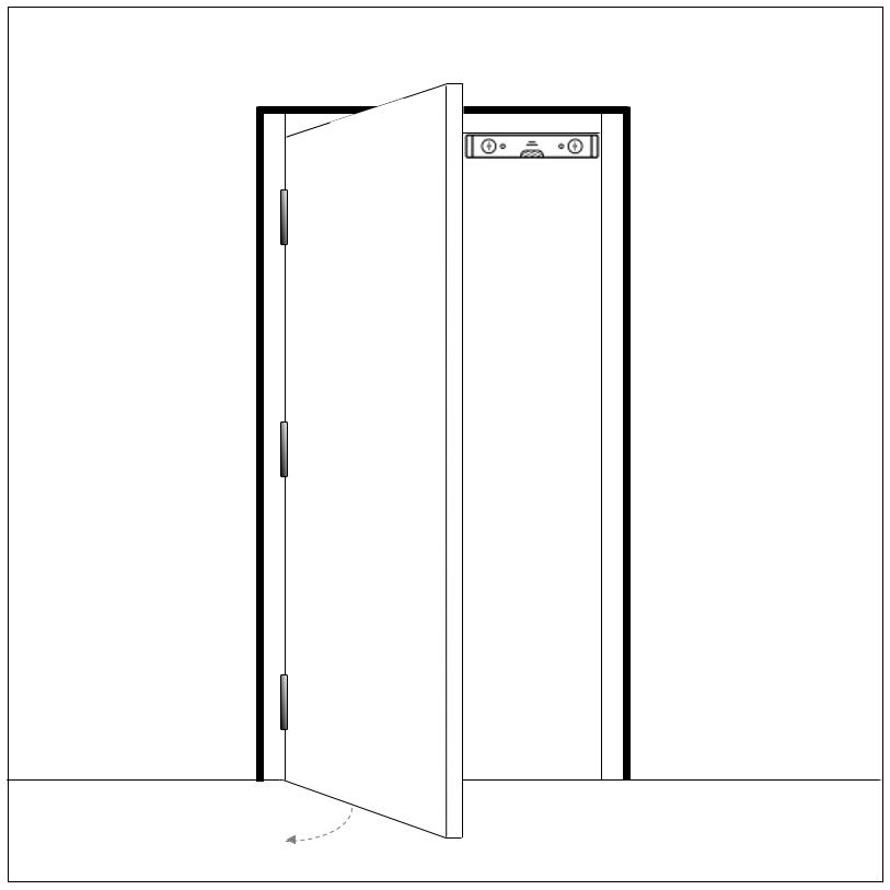
1. Insert the door and frame into the opening, and open the door to 90o
2. Place the spirit level parallel to the frame. If the head of the frame is not level, use packers to raise the lowest side of the frame to level.
3. Once the frame is aligned, fill the gaps between the frame and the structure with packers to centralise the door and even out the gaps around the frame.
4. Level up the front face of the hinge post, ensuring the top of the frame does not lean in or out of the opening.
5. Drill and insert fixings into top and bottom fixing holes, and place packers close to the fixings. Do not tighten the fixings.
6. Position frame centrally in opening, with hinge post vertical. Double check the door alignment with a spirit level, then tighten fixings.
7. Drill the rest of the holes on each post and insert middle fixings. Do not tighten the fixings.
8. Place packers between the frame and the wall, adjacent to fixings, then tighten fixings.
9. Use the same method to secure the top sill in position.
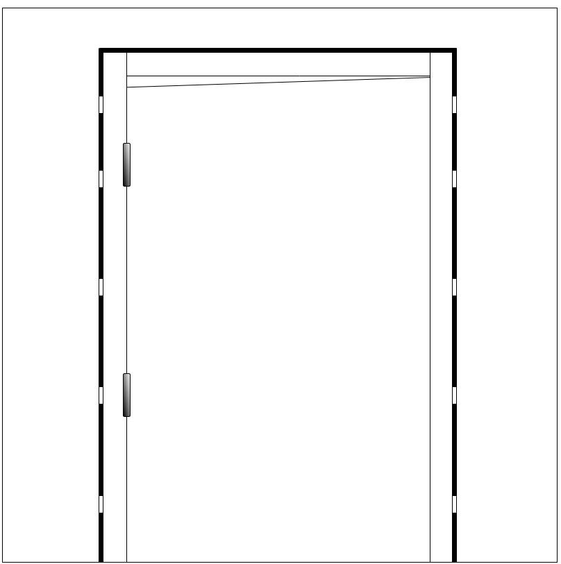
10. Close door leaf to test it in the frame. If the leading edge is too high, add packing towards the top edge of the hinge post. If it’s too low, then reduce packing towards the top edge.
11. Once adjustments are made, drill and insert fixings into lock post. Do not tighten the fixings.
12. Insert packers between the frame and wall fixing, then tighten fixings. Do not over pack between the frame and the wall.
13. Test the door hardware and operation. Any panic hardware must have the opening force measured and recorded in the operation and maintenance manual.
14. Fit the bottom sill (if present). Level up with shims so it is parallel with the bottom of the door leaf, then drill and fit to floor.
15. Mastic seal around the door frame and bottom sill (inside and outside), as required.
16. Plug the fixing holes in the frame with bungs.
17. Re-check operation of the doorset.
Step 10
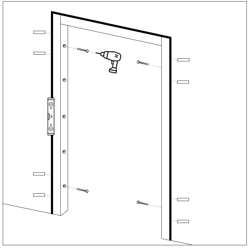
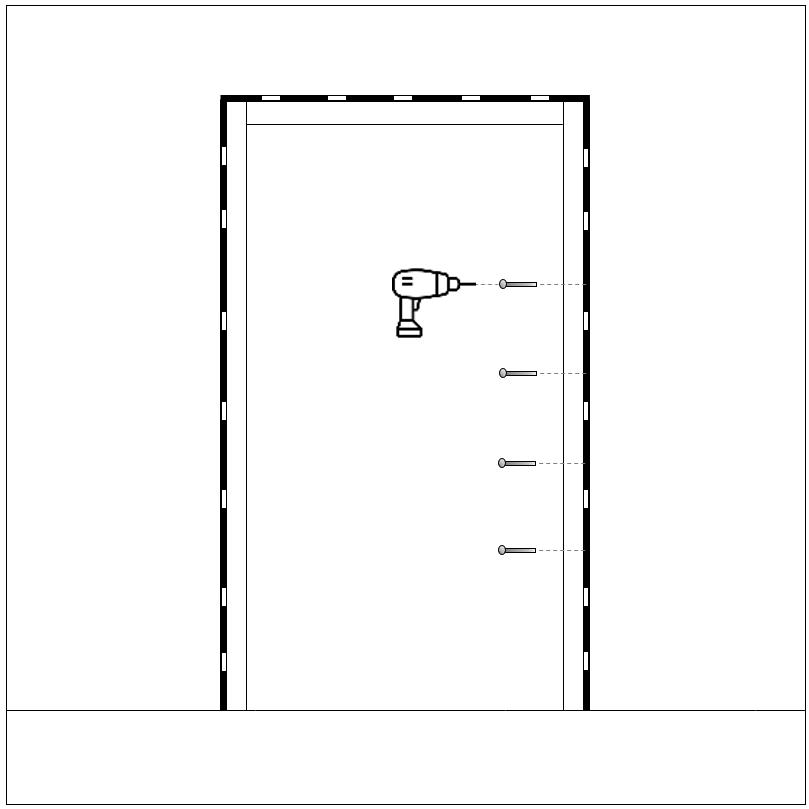
Steps 11-13

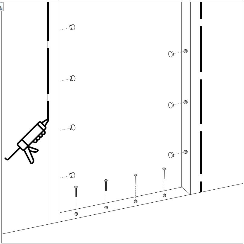
Steps 14-17
M2M Fitting Instructions 05-04GB, 02-24 10
Steps 1-4
Steps 5-6
Steps 7-9
DOUBLE DOORS WITHOUT ADJUSTERS
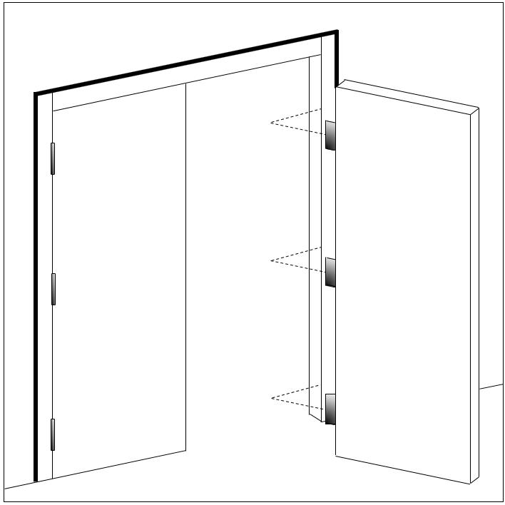
1. Assemble the door frame using fixing blocks and screws, then insert the frame into the opening.
2. Place the spirit level parallel to the frame. If the head of the frame is not level, use packers to raise the lowest side of the frame to level.
3. Once the frame is aligned, fill the gaps between the frame and the structure with packers to centralise the door and even out the gaps around the frame.
4. Level up the front face of the first hinge post, so the frame does not lean in or out of the opening.
5. Drill and insert fixings into top and bottom fixing holes. If the doors are heavy, add one or two fixings to the middle of each post as well. Place packers close to the fixings. Do not tighten the fixings.
6. Position frame centrally in opening, with the first hinge post vertical. Double check the door alignment with a spirit level, then tighten fixings.
7. Hang the doors on the frame, then close the doors to check that they shut correctly and are hanging level, and test the door hardware.
8. If the doors bind at the top, remove some of the packing from both sides at the top of the frame and tighten the fixings. If the doors are binding at the bottom, remove some of the packing from the bottom.
9. Once the doors are positioned and working satisfactorily, drill the rest of the holes on the hinge posts and insert fixings. Do not tighten the fixings.
10. Place packers between the frame and the wall, adjacent to each of the fixings, then tighten fixings. Do not over pack between the frame and the wall.
11. Use the same method to secure the top sill in position.
12. Test the door hardware and operation. Any panic hardware must have the opening force measured and recorded in the operation and maintenance manual.
13. Fit the bottom sill (if present). Level up with shims so it is parallel with the bottom of the door leaf, then drill and fit to floor.
14. Mastic seal around the door frame and bottom sill (inside and outside), as required.
15. Plug the fixing holes in the frame with bungs.
16. Re-check operation of the doorset.
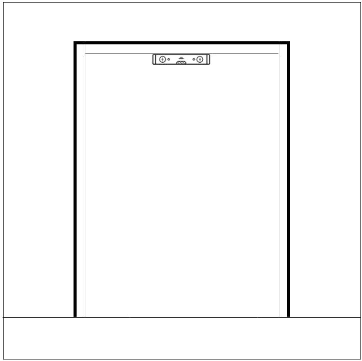
Steps 1-4

Step 8
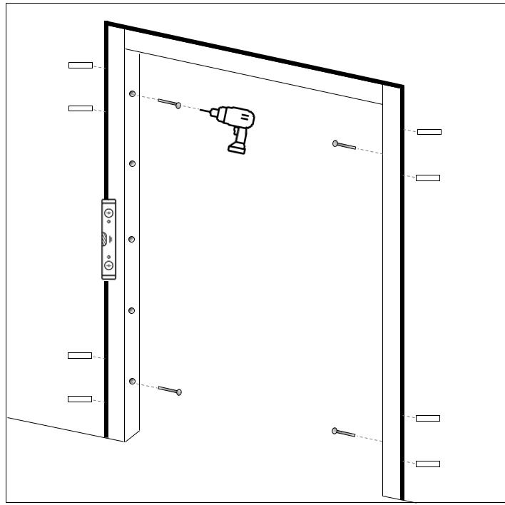
Steps 5-6
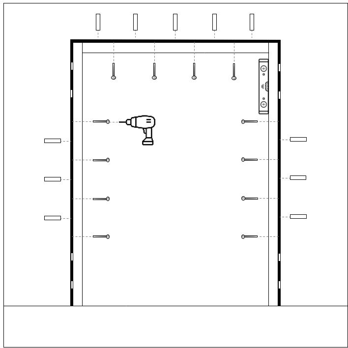
Steps 9-11

Step 7
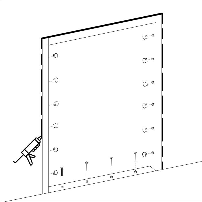
Steps 12-16
M2M Fitting Instructions 05-04GB, 02-24 11
1. If fitting a Capital45 door, please insert the adjusters prior to inserting the door frame into the structural opening.
2. Insert the door and frame into the opening, and open the door to 90o, using packers underneath the door leaf to level the frame in the opening.
3. Place the spirit level parallel to the frame. If the head of the frame is not level, use packers to raise the lowest side of the frame to level.
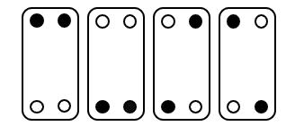
4. Once the frame is aligned, screw the adjusters through the tapped holes using the hex tool supplied, ensuring the door is central in the opening. Adjusters must be arranged using one or more of the following patterns:

5. Level up the front face of the hinge post, ensuring the top of the frame does not lean in or out of the opening.
6. Using the hex tool supplied, fasten the top adjusters, then the bottom adjusters, and finally the middle adjusters. Care must be taken not to distort the frame by over-tightening the adjusters.
7. Close door leaf to test it in the frame. If the leading edge is too high, loosen the adjusters at the top edge of the hinge post. If it’s too low, then tighten the adjusters towards the top edge.
8. Once adjustments are made, drill and insert fixings down both vertical posts. Do not tighten the fixings.
9. Double check the door alignment with a spirit level, then tighten fixings.
10. Test the door hardware and operation. Any panic hardware must have the opening force measured and recorded in the operation and maintenance manual.
11. Fit the bottom sill (if present). Level up with shims so it is parallel with the bottom of the door leaf, then drill and fit to floor.
12. Mastic seal around the door frame and bottom sill (inside and outside), as required.
13. Plug the fixing holes in the frame with bungs.
14. Re-check operation of the doorset.

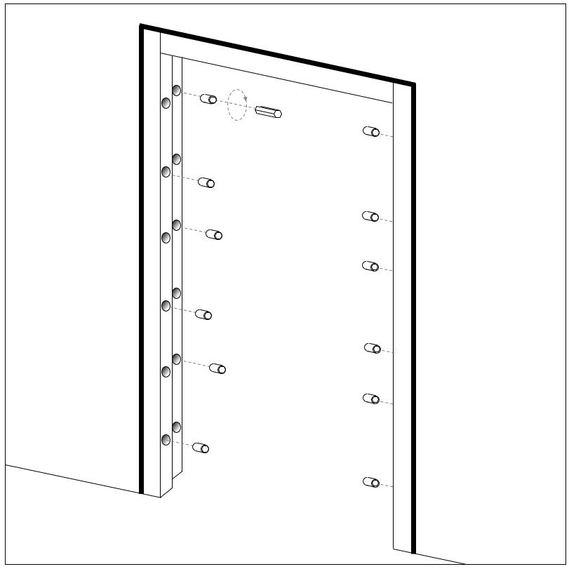
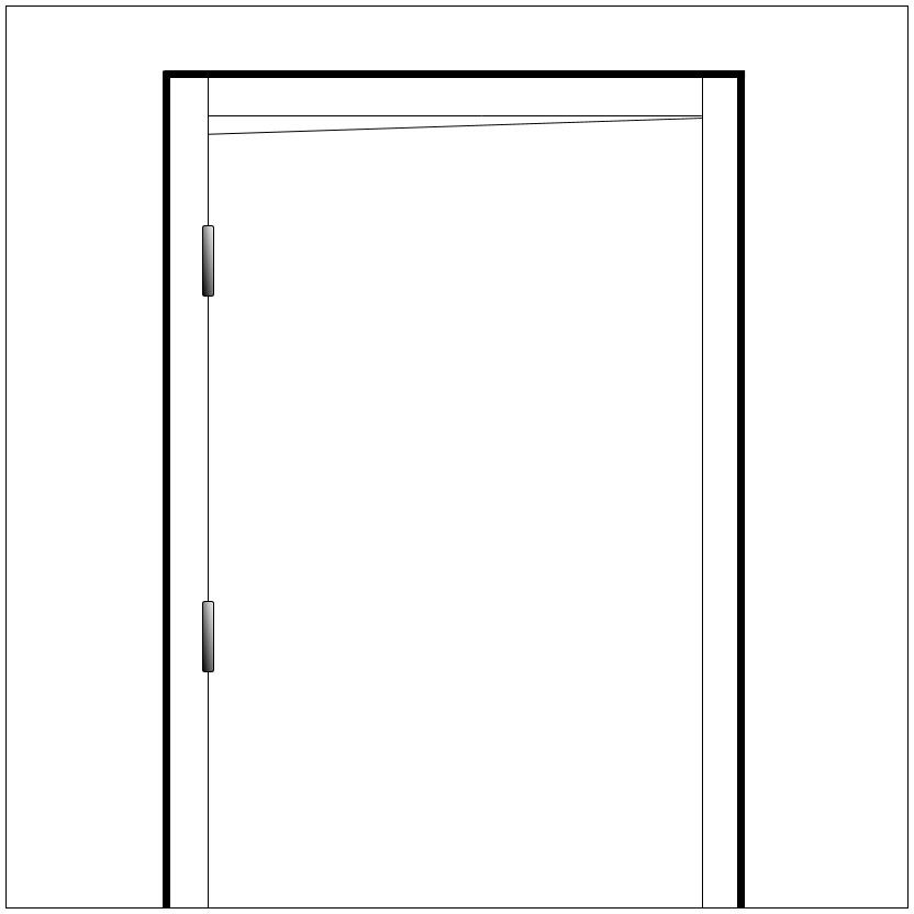
Steps 3-5

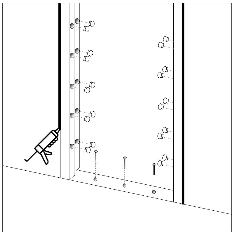
M2M Fitting Instructions 05-04GB, 02-24 12
Steps 1-2
Step 6
Steps 7-9
SINGLE DOORS WITH ADJUSTERS
Steps 10-13
DOUBLE DOORS WITH ADJUSTERS
1. If fitting a Capital45 door, please insert the adjusters prior to inserting the door frame into the structural opening.
2. Assemble the door frame using fixing blocks and screws, then insert the frame into the opening.
3. Place the spirit level parallel to the frame. If the head of the frame is not level, use packers to raise the lowest side of the frame to level.
4. Screw the adjusters through the tapped holes using the hex tool supplied, ensuring the door is central in the opening. Adjusters must be arranged using one or more of the following patterns:
5. Level up the front face of the first hinge post, ensuring the frame does not lean in or out of the opening.
6. Drill and insert fixings into top and bottom fixing holes. If the doors are heavy, add one or two fixings to the middle of each post as well. Place packers close to the fixings. Do not tighten the fixings.
7. Position frame centrally in opening, with the first hinge post vertical. Double check the door alignment with a spirit level, then tighten fixings.
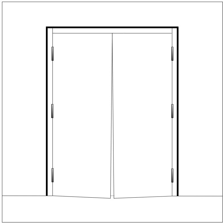
8. Hang the doors on the frame, then close the doors to check that they shut correctly and are hanging level, and test the door hardware.
9. If the doors bind at the top, loosen the adjusters on both sides at the top of the frame. If the doors are binding at the bottom, loosen the adjusters at the bottom.
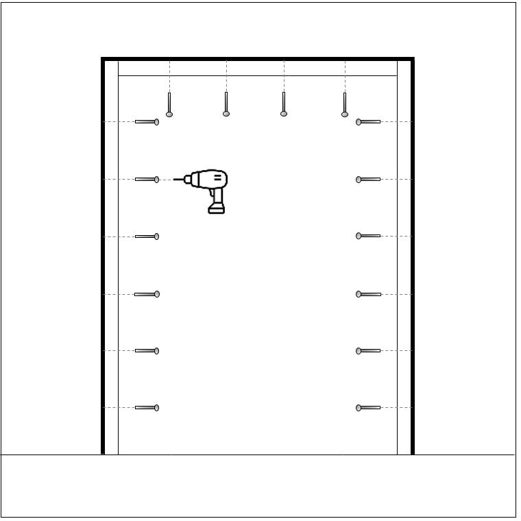
10. Once adjustments are made, drill and insert fixings on all posts. Do not tighten the fixings.
11. Double check the door alignment with a spirit level, then tighten fixings.
12. Test the door hardware and operation. Any panic hardware must have the opening force measured and recorded in the operation and maintenance manual.
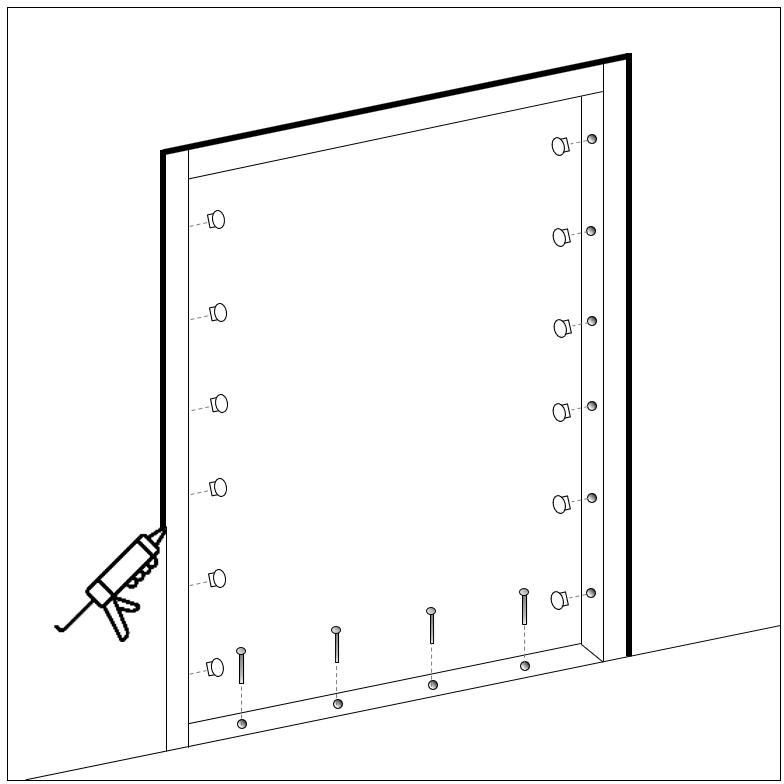
13. Fit the bottom sill (if present). Level up with shims so it is parallel with the bottom of the door leaf, then drill and fit to floor.
14. Mastic seal around the door frame and bottom sill (inside and outside), as required.
15. Plug the fixing holes in the frame with bungs.
16. Re-check operation of the doorset.

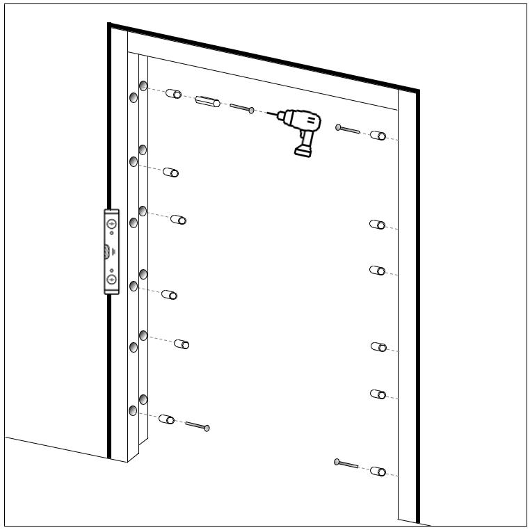
Step 7

Steps 8-10
M2M Fitting Instructions 05-04GB, 02-24 13
Steps 1-2
Steps 3-5
Step 6
Steps 11-14
1. Mastic sealant
2. Mastic gun
3. Utility knife
4. Clean cloth/small straight edge item i.e. plastic packer
5. Mastic finishing tool (optional)
Steps
Preparation
- Ensure both the door frame and substrate surface are clean and free from dust, debris, grease or any other containments.
Cut the nozzle
- Cut the nozzle of the mastic sealant at a 45-degree angle to the desired bead size. The size of the nozzle cut will depend on the size of the gap between the steel frame and substrate.
Apply sealant
- Load the mastic sealant into the gun and apply a continuous bead of sealant along the gap between the frame and the substrate. Apply steady pressure on the gun trigger to ensure a consistent bead. Move the gun smoothly along the entire length of gap.
Tool the sealant
- After applying the sealant, use a mastic tool or a rounded tool (or a wet finger) to smooth out the sealant and ensure it fully fills the gap between the frame and substrate. This also helps ensuring a good adhesion.
Remove excess sealant (optional)
- If you accidently applied more mastic sealant than required, remove any excess with a clean rag or a suitable item such as a plastic packer. Ensure the item will not damage the frame and be careful not to disturb the sealant that has already been applied.
Allow to cure
- Allow the sealant to cure according to the manufacturers instructions. This typically involves keeping the area free from disturbance and moisture for a specified period.
PLEASE NOTE
- When fitting a flood door, please ensure flood mastic is to be used.
- When installing a fire rated door, please follow the manufacturers instructions for application and ensure proper installation to maintain the fire rating of the door. Incorrect installation or use of non-rated sealants can compromise the fire resistance of the door.
M2M Fitting Instructions 05-04GB, 02-24 14
SEAL
MASTIC
GENERAL GUIDE

+44 (0)1724 271999
enquiries@bradbury-group.com
6 Atkinsons Way
Foxhills Industrial Estate
Scunthorpe
North Lincolnshire
DN15 8QJ
United Kingdom
www.bradbury-group.com


M2M Fitting Instructions 05-04GB, 02-24 15


