
Ventilation for New Build Residential Edition 5.8 The UK’s Leading Ventilation Company www.vent-axia.com/new-build

Vent-Axia has been the UK market leader for over 80 years and has vast experience in supplying heat recovery solutions to the UK and countries around the world, whose building regulations demand the most effective, sustainable and energy efficient ventilation solutions.

• Unparalleled customer service
• Industry leading design support
• Providing support and solutions on-site
•
• With the widest distribution network of any manufacturer in the UK we pride ourselves on having products available when and where you need them
• Whatever the product application, we have the most energy efficient solutions available
• Unique solutions designed to fit into all your buildings
• With absolute focus on the end user we work hard to produce the quietest, most comfortable products for occupiers to live with

With a housing shortage in the UK and an increase in building on flood plains, or land at risk of flooding, the Floating Home offers an exciting house building solution. Inspired by canal living and designed by Baca Architects, the ‘Chichester’ prototype model was built by Floating Homes Limited and is not a houseboat but a house that floats. Situated on a residential mooring on a disused canal which runs alongside Chichester Marina in West Sussex, the Floating Home was built in two separate parts, the floating foundations and the modular superstructure and then assembled on the canal. The whole build took four months to complete and fit out, including installation of Vent-Axia’s Sentinel Kinetic BH MVHR Unit.
Essentially the home was built in the same way as one on land but the foundations float. However, given the close proximity to water there was potential for more humidity than a land-based home, as well as the potential for reflections of the sun to enhance solar gain. Both these factors were considerations when specifying the Sentinel Kinetic BH MHVR unit.
Built Environment Technology Ltd designed and commissioned the ventilation system for the project. Richard Porteous, Senior Projects Manager at Built Environment Technology Ltd explains: “Due to the very low permeability of the home’s envelope mechanical ventilation was essential. The Sentinel Kinetic BH MVHR Unit had the right ecocredentials for the project, plus it is very compact and features an integral humidity sensor and summer bypass, which were important for the Floating Home.”
“Having lived in and visited houseboats that did not have MVHR it was clear that this technology was essential for the air quality and sustainability of our floating homes. We also specified Vent-Axia for its reputation, Vent-Axia has been at the forefront of ventilation for over 80 years, and is a British manufacturer of high repute. Of course they fit the Floating Homes ethos!,”
Recovering up to 90% heat energy
“Due to the very low permeability of the home’s envelope mechanical ventilation was essential. The Sentinel Kinetic BH MVHR Unit had the right ecocredentials for the project, plus it is very compact and features an integral humidity sensor and summer bypass, which were important for the Floating Home.”
Mark Junak from Floating Homes.


The Virido development offers future living with a collection of 208 unique apartments, duplex apartments and townhouses that offer a more sustainable lifestyle arranged around an open green space. Brimming with eco-design, the homes are architecturally pleasing, triple-glazed and clad in brick and dark timber. The Ventilation system was designed, installed and commissioned by DR Ventilation using Vent-Axia's Lo-Carbon Sentinel Kinetic BH and Lo-Carbon Sentinel Kinetic Plus Mechanical Ventilation with Heat Recovery (MVHR) units, providing energy efficient and effective ventilation to these sustainable homes.
To meet Code for Sustainable Homes Level 5, the homes in the sustainable development in Cambridge have been designed and constructed to be highly energy efficient and to reduce carbon emissions by 100%. To achieve this the homes at Virido have been designed to use as little energy and water as possible. Virido’s homes provide exceptional standards of insulation. Using Structurally Insulated Panels (SIP), approximately 4 times more insulation than an average new build home is achieved. The walls provide approximately 20% less heat loss than a typical building without compromising on room sizes. With such high levels of insulation and air tightness MVHR was vital to provide good air ventilation to the homes.
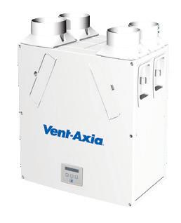
The pioneering Sentinel Kinetic BH MVHR Unit is designed specifically for new build and low-permeability properties. A whole-house, multiroom ducted solution, this MVHR system combines supply and extract ventilation in one unit. Warm, moist air is extracted from `wet' rooms through ducting and passed through the heat exchanger before being exhausted to the outside. Fresh incoming air is filtered and then preheated via the integral heat exchanger which recovers an average of 90% of the heat energy that would otherwise be wasted. With comfort key for occupants the system also features a `summer bypass', for passive cooling when conditions allow and an integral humidity sensor for intelligent air quality control, which are vital in thermally efficient air tight homes.
“The homes in the Virido development feature very high levels of insulation, air tightness and thermal efficiency which meant it was essential to specify MVHR in order to provide good levels of ventilation within the properties. We specified Vent-Axia's MVHR because of their ecocredentials offering both energy efficient ventilation and good comfort for households. Having worked on many developments we have great confidence in Vent-Axia's products and a professionally installed system with an efficient MVHR unit provides a winning combination.”
Helen Roberts, Director, DR VentilationThe Sentinel Kinetic BH and Sentinel Kinetic Plus MVHR units both fit with the Virido's project objective which is to provide homes that effortlessly facilitate a lifestyle which is both environmentally responsible and sustainable without compromising on comfort.
Approved Documents F (ADF) and L (ADL) of the Building Regulations were issued in October 2010. ADL was further revised in 2013. They place much greater emphasis on effective design, installation and operation of ventilation systems. The objective is to maximise carbon reduction through correctly specified and designed systems, competent installation minimising losses of the systems, verified performance once installed and correct operation by the home owner.
This section explains how to achieve compliance, looking at the three key areas in detail: Specification and Design, Installation and Commissioning, Operation and Maintenance.
ADF, Means of Ventilation, is the document which addresses the performance requirements of different ventilation systems. Factors such as airflow rates, noise and occupiers operation are all covered here.
The latest edition has a few top level changes which may mean something to you (we will cover them in more detail in each section later on) but as an overview they are as follows:
The ventilation rate of a given property is calculated dependant on the designed infiltration rate. Basically, how much air leaks in or out of the dwelling (anyone who has lived in a drafty house will understand the importance that this has!). The airtightness of a building is defined as its air permeability; this is the volume of air that escapes through the envelope of the building per hour (m3/h.m2).
There is guidance on good installation practice and a commissioning guide set out in a supporting document to ADF known as the Domestic Ventilation Compliance Guide. This has been designed to ensure that ventilation not only delivers the required airflow, but also does it efficiently and quietly. The document also links in with the competent persons schemes and training programmes run by the industry.
ADL, the document concerning fuel and power, covers the efficiency and energy consumption of ventilation products, among others. Putting it simply ADL has improved the energy efficiency targets for buildings by 30%, with further improvements through target emission rate. There is also an opportunity to save energy through ventilation by using SAP Performance Characteristics Database (PCDB), formerly known as Appendix Q. This is a method by which energy efficient ventilation systems can be selected and the energy benefit be added back into the SAP calculation.
Ventilation uses energy in two ways. Firstly, mechanical systems use electricity to power the motors and secondly heat is lost as heated air is extracted from a building. This is now dealt with by a minimum energy efficiency level for all ventilation systems being set in a supporting document called The Domestic Building Services Compliance Guide. There are now for the first time new build and refurbishment minimums in both the amount of electricity a motor can use minimum specific fan power (SFP) and a minimum energy efficiency of heat exchangers in systems that can recover heat.
We recommend that best practice is followed when designing and installing a system, as the product performance is affected by both areas.
There are four systems covered in the building regulations and these are as follows:
System 1
Intermittent fans and background ventilation
System 2
Passive stack
System 3
Continuous Mechanical Extract Ventilation (MEV and dMEV).
System 4
Continuous mechanical supply and extract ventilation with heat recovery (MVHR). We will be looking at these in more detail under separate sections later in this brochure.
There are four areas for consideration when selecting ventilation:
• Airflow performance
• Minimum energy efficiency limits
• Good installation
• Use by occupiers
Leaky House
For properties leakier than 5m³h/m² infiltration.
Non Leaky House
For properties tighter than 5m³h/m² infiltration. Basically, tighter buildings now have an increased ventilation rate.
There are some considerations dependant on which ventilation system is being used. These are outlined here but are shown in more detail in the separate sections for each system.
Intermittent Fans and Passive Stack (System 1 and 2) These have different levels of background vents dependant on the infiltration rate of the building.
MEV (System 3)
Window vents are not needed in leakier buildings.
MVHR (System 4)
The rate of ventilation can be reduced dependant on the leakage of the building. If the building is leakier than 5m³h/m² then the mechanical ventilation rate is reduced.
Noise
Noise is now covered by the building regulations. As our buildings become more energy efficient and more air tight, the amount of noise entering them from outside is reduced. This has the effect of making them much quieter inside. That means that any noise made inside the house will be more noticeable so ADF now recommends a maximum noise level for any continuous system of 35dB(A).
The table below shows the airflow rates as described in ADF. Table
Energy Efficiency
As mentioned earlier, there are energy efficiency limits for all of the systems covered in the building regulations as well as some minimum heat exchanger efficiencies for heat recovery products. These are as follows:
Specific Fan Power (SFP)
• Intermittent extract fans - specify a maximum of 0.5 W/l/s
• Continuous extract fans - specify a maximum of 0.7 W/l/s
• Continuous supply and extract fans (MVHR) - specify a maximum of 1.5W/l/s
Heat Exchanger Efficiency
There is a requirement for any heat exchanger in a residential property to be a minimum of 70% efficient.
New Build
Building Regulations favour continuous ventilation as these products perform better in SAP, are easier to specify and easier to standardise (no need for trickle vents). This encourages new build designers to move new planning applications away from intermittent fans. Vent-Axia has the solution with Centra, Lo-Carbon dMEV and Quadra as some of the best performing products on SAP PCDB (Appendix Q).
Refurbishment
The Lo-Carbon intermittent range is essential to the refurbishment sector complying with the SFP of 0.5W/l/s. Giving benefits of 80% reduction in power consumption, 5 Year Motor Guarantee, the fans are suitable for wall, window, ceiling or ducted applications.
The whole Lo-Carbon residential range of fans meet the requirements of 0.5 W/l/s
Notes:
a. In addition, the minimum ventilation rate should be not less than 0.3 l/s per m2 of internal floor area. (This includes all floors, e.g. for a two-storey building add the ground and first floor areas).
b. This is based on two occupants in the main bedroom and a single occupant in all other bedrooms. This should be used as the default value. If a greater level of occupancy is expected add 4 l/s per occupant.
Intermittent extract fan airflow rate based on table 5.1a from the previous page.
The design air permeability will determine the equivalent ventilator area as laid out in the tables.
This system relies on the natural stack effect by which warm air rises and is extracted from the wet rooms through 125mm rigid ducts running to ridge height. Trickle vents are required and can be humidity controlled. Internal rooms require ‘assisted’ ventilation i.e. by mechanical ventilation.
Much larger equivalent areas (up to 50% bigger) are now required for background ventilators when using system 1 and 2.
For example a three bed house with a floor area of 100m² a total equivalent area of 65000mm² is required. This may only have six windows to fit them in which would mean a free area of 10,833mm in each window. This not only takes up a lot of space in each window frame and looks unsightly, but the window fabricator will charge to fit each one and this example could require three vents on each window.
A - Total equivalent ventilator area a (mm2) for a dwelling with any design air permeability.
B -Alternative guidance on total equivalent ventilator area3 (mm2) for a dwelling with a designed air permeability leakier than (>) 5m3/ (h.m2) at 50 Pa.
The requirement for reduced specific fan powers means that no intermittent fan can use more than 0.5 W/l/s.
Vent-Axia offers a fully compliant Lo-Carbon intermittent range which meets both ADF and ADL.
Range Features
• Models: Basic/Timer/Humidity - Installation options
• Low power consumption - ADL Compliant
• Quiet running
• Back draught shutters included
• Modern aesthetics
• Ball bearing motors for vertical or horizontal application
• 5 year motor guarantee
• Wall, ceiling, panel and window mounting options available
There are two ways to comply with system 3: Centralised (MEV) or Decentralised (dMEV).
MEV incorporates a single unit that extracts stale air to atmosphere from all the wet rooms via ducting.
Decentralised MEV requires continuous running extract fans mounted in all wet rooms in much the same way as a traditional fan is mounted.
As shown on page 7, rates as per table 5.1a for the continuous systems are much lower than intermittent ventilation, and in kitchens particularly the rate falls from 60l/s to 13l/s. This can remove the requirement for noisy fans or cooker hoods completely.
An additional benefit is through a reduction in the number of background vents needed. If the design air permeability is <5m3/(h.m2)@50Pa, background ventilators are required in habitable rooms at 2500mm² only. This is one small vent. If design air permeability is >5m3/(h.m2)@50Pa there is no requirement for background ventilators at all. This offers the benefit of not having to install several unsightly window vents, as required with intermittent systems.
Lo-Carbon Quadra
The Domestic Building Services Compliance Guide states a maximum specific fan power (SFP) of 0.7W/l/s for MEV systems. These can also be SAP PCDB eligible which enables selection during the SAP calculation (there is an eligible product list embedded within the SAP software programmes). This enables the difference between the specific product and the default settings within SAP.
Vent-Axia Lo-Carbon Multivent ranges incorporate energy efficient EC/ DC motors providing SFPs down to 0.15W/l/s which is over 75% savings over the default 0.7W/l/s in SAP. This low SFP makes it one of the most efficient MEV products available.
In much the same way, dMEV can be applied and the Vent-Axia LoCarbon dMEV also provides SFPs down to 0.13W/l/s which is up to a 82% saving over the default 0.7W/l/s in SAP. This also makes it one of the most efficient dMEV products available.
Installation
The 2010 regulations also require that systems are installed and commissioned correctly. To help, we provide training courses. For more information, please see the training scheme section located on page 13.
Lo-Carbon Multivent MVDC-MS/MS-H
Range Features
• Market leading efficiency
• Digital controls with display
• Fully adjustable normal & boost airflow settings
• 100mm & 125mm model
• Recognised in SAP PCDB
• Constant volume
• Display showing airflow and system pressure
• Switched live connection for external switches/sensors
• IPX5 rated
• Multi--orientation grille
• NHBC Approved
• STAS Approved (Scotland)
• Airflow sensor models UKAS calibrated

Range Features
• Single fan for use in toilets, bathrooms, utility rooms and kitchens
• Meets Building Regulations for intermittent or continuous use

• Guaranteed installed performance
• ADF compliant - meets airflow rates in table 5.1a and 5.1b
• ADL compliant - SFP 0.38W/l/s
• Suitable for wall, ceiling and panel mounting

• Filterless technology and maintenance free
• Lo-Carbon motors offering 90% energy savings and long life
Range Features
• Recognised in SAP PCDB with best in class Specific Fan Power
• Reduces your carbon footprint
• Fitted with three extract 125 diameter spigots allowing quick connection to ducts
• Complies with Building ADF (System 3)
• Option of wall, ceiling and loft mounting
• Improved controllability
• Two Switched Live connections
• Fully variable normal, purge and boost speeds
• Ultra quiet
• Integral humidistat (H version)
SAP PCDB Test Results
MVHR is a whole dwelling ventilation system that supplies and extracts air continuously at a low rate (as per table 5.1b) with the facility to be boosted as required. The unit is normally installed in the loft space or cupboard and rigid ducting supplies fresh filtered air to the habitable rooms and extracts stale polluted air from the ‘wet’ rooms.
Supply and extract diffusers are fitted to the ceilings and are adjusted to balance the system.
The unit incorporates a polymer heat exchanger that tempers the incoming air before it is delivered to the habitable rooms.
The Domestic Building Services Compliance Guide specifies a maximum specific fan power of 1.5 W/l/s for MVHR systems.
Commissioning
MVHR systems must be commissioned in compliance with ADF with notification to Building Control and a copy provided for the owner/occupier.
Lo-Carbon Sentinel Kinetic BH, FH
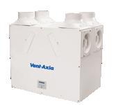
Lo-Carbon Sentinel Kinetic Plus & High Flow
Additional Advance Features
• Best in class SFP's and thermal efficiencies up to 93%
• Approved Document F aligned commissioning wizard
• New Sentinel-X wireless control platform
• Intelligent smart app control as standard
• Horizontal duct option for space-saving installations (M & L only)
• ISO ePM10 (M5) and ePM2.5 (F7) filtration options
• Sound levels as low as 15.5 dB(A) breakout - independently tested and verified by SRL
• Left/right handing via controls
• Developed and manufactured in the UK
• Acoustic enclosure and top box options (S only)
SAP PCDB Performance
Additional Sentinel Features
• Programmable summer bypass
• Integrated digital controller for simple and accurate commissioning

• Plug and play controls: Humidistat, Vent-Wise, PIR

• Wired remote control and wireless boost options
• Volt-free inputs
• Adjustable delay-off timer
• BMS connectivity
• Self diagnosis for simplified fault finding
• 0V to 10V proportional control
• Purge setting
• Cooker hood option
Kinetic BH SAP PCDB Performance
Additional Kinetic Plus Features
• 150mm spigots with 180mm and 200mm options
• Up to 200l/s (720m3/hr at 150Pa)
• Hinged filter for simplified access
Kinetic Plus SAP PCDB Performance
Kinetic FH SAP PCDB Performance
Kinetic High Flow SAP PCDB Performance
House Specification
MEV/ Airflow l/s dMEV Normal Boost Kitchen 10 13
Bathroom 6 8 WC 4 6
En-Suite 6 8 Total 26 35
Three bedrooms, kitchen/dining room, living room, WC, bathroom, en-suite floor area 85m2
Whole dwelling rate (background, trickle or normal rate) calculate the rate from ADF, table 5.1b: 26l/s based on ‘Note a’; 85m2 x 0.3l/s = 26l/s
Calculate the extract ventilation rate (boost) from ADF, table 5.1a: kitchen (13l/s) + WC(6/ls) + bathroom (8l/s) + en-suite (8l/s) = 35l/s.
Background Ventilators (if needed)
Living room 2500mm2
Kitchen/dining 2500mm2
Bed 1 2500mm2
Bed 2 2500mm2
Bed 3 2500mm2
Total 12500mm2
Apartment Specification
Determine the whole dwelling rate as above (26 l/s). Calculate the room supply rate for the SRHRV: (Room volume x whole dwelling rate)/ (Total volume of all habitable rooms) e.g. (36m3 x 26l/s)/(132m3) = 7l/s. The new whole dwelling rate for the MEV system is 19l/s. The SRHRV rate is 7l/s.
Apartment Specification Airflow
One bedroom, kitchen/dining/living room, bathroom floor area 50m2
Whole dwelling rate (background, trickle or normal rate) calculate the rate from ADF, table 5.1b: 15l/s based on ‘Note a’; 50m2 x 0.3l/s = 15l/s.
One bedroom, kitchen/dining/living room, bathroom floor area 50m2
Whole dwelling rate (background, trickle or normal rate) calculate the rate from ADF, table 5.1b:15l/s based on ‘Note a’; 50m2 x 0.3l/s = 15l/s.
Calculate the extract ventilation rate (boost) from ADF, table 5.1a: kitchen (13l/s) + bathroom (8l/s) = 21l/s.
Background Ventilators (if needed)
Living/dining rm 2500mm2 Bed 1 2500mm2
Total 5000mm2
Single room heat recovery ventilator (SRHRV) may be used in conjunction with MEV/dMEV systems.
Three bedrooms, kitchen/dining room, living room, WC, bathroom, en-suite floor area 85m2
Whole dwelling rate (background, trickle or normal rate) calculate the rate from ADF, table 5.1b: 26l/s based on ‘Note a’; 85m2 x 0.3l/s = 26l/s. Airflow
Calculate the extract ventilation rate (boost) from ADF, table 5.1a: kitchen (13l/s) + bathroom (8l/s) = 21l/s
Apartment Dimensions:
Ground floor
10m x 5m x 2.4m (room height)
Total dwelling volume = 120m3
120m3 x 0.04l(s.m3) = 4.8l/s infiltration
Whole dwelling rate – Infiltration
15 l/s - 4.8 l/s = 10.2 l/s
Calculate the extract ventilation rate (boost) from ADF, table 5.1a: kitchen (13l/s) + WC (6l/s) + bathroom (8l/s) + en-suite (8l/s) = 35l/s.
House Dimensions: Ground floor
8.5m x 5m x 2.4m (room height)
First Floor
8.5m x 5m x 2.4m (room height)
Total dwelling volume = 204m3
204m3 x 0.04l(s.m3) = 8.2 l/s infiltration
Whole dwelling rate – Infiltration
26l/s - 8.2l/s = 17.8l/s
For buildings leakier than 5m3/(h.m2), you must subtract natural infiltration from the whole dwelling (normal) rate: calculate the internal volume of the dwelling. Multiply the internal volume by 0.04l/(s.m3) subtract this volume from the whole dwelling rate.
As part of the ongoing drive for energy efficiency within Europe, as of January 2016 ventilation devices over 30 Watts now come under the scope of the Energy Related Products Directive. The legislation sets minimum performance criteria across a range of fans and ventilation devices under two sets of legislation; ‘residential’ ventilation and ‘non-residential’ ventilation. Additional and stricter criteria came into force as of January 2018.
Residential Products has a secondary directive which requires some products to carry an energy label as described below:
These products do come into the scope of the legislation and will carry an energy label. There are some minimum energy efficiency requirements as well as the requirement for a summer bypass on heat recovery models.
Products within the scope of ErP now need to carry a rating that shows their Energy Efficiency Class. This information is called a ‘SEC Class’ and is provided in all product literature and on the energy label.
A product’s SEC class is affected by how the product is controlled. This is referred to as Local Demand Control (LDC) and indicates how many ‘sensors’ a fan should have. The regulations require that single room fans, such as a bathroom fan, should have at least 1 sensor. Units that are ducted, such as an MEV unit, need to have more than one sensor. Examples of these are a pull cord/light switch or humidistat.
In our literature, where appropriate we have shown the rating if an additional LDC was added to a product. In those cases, you will see a table similar to the one below which has a heading (incl LDC). This is so you can choose the most efficient option for your needs.
Non-Residential products have had minimum performance and efficiency levels established, but there is no requirement to introduce energy labels. Some products have been updated with new motors and enabled for speed control.
Non-Residential ranges are split into a number of different categories dependent on their application and function. These can be described as follows:
1. Fans
2. Uni-directional Ventilation Units
3. Bi-directional Ventilation Units
There are very few suppliers of products and services within the building and construction industry that can provide a complete and fully integrated service to their clients.
With over 80 years' ventilation experience, Vent-Axia continues to lead the way in the development of new products and systems. As legislation drives the development of ventilation systems and services Vent-Axia provides a dedicated team of mechanical ventilation systems experts within the VentAxia New Build - Residential Team.
This experienced systems ventilation team and the full support service provides the contractor with an alternative to specially trained internal staff and hence reduces the liabilities for the client.
From an initial enquiry Vent-Axia will take full responsibility of system design, supply of its equipment, commissioning and balancing. Completed Inspection Checklists are provided for the client and contractor.

Vent-Axia firmly believes significant advantages can be achieved by its clients in having all diverse and complex project services integrated under one roof. Key advantages are effective co-ordination, economies of scale and a seamless support structure. Vent-Axia has a dedicated team of experienced, highly qualified technicians, service personnel and engineers who are at the forefront of engineering technology.
Once an enquiry has been received, either direct from the customer or following a site visit by one of Vent-Axia’s experienced field representatives, a dedicated team is assigned to the project.
Using bespoke ventilation computer aided design software, Vent-Axia will produce sample system designs, showing unit location, ducting runs, air flow rates and noise considerations. This enables the designer to produce an accurate price for the supply of ventilation unit, ducting and accessories for the whole development.
With over 2000 distributors nationwide, Vent-Axia can ensure availability and on-time service to site.

Commissioning and balancing is undertaken by Vent-Axia Supervisors or approved contractors. Using anemometer hoods, airflow readings are taken and recorded on commissioning sheets.

Any adjustments to the unit or the adjustable diffusers are made to ensure the system meets the design intent. This stage is essential to ensure that the installed performance requirements of the Building Regulations are satisfied. Vent-Axia can provide installation training certified by NICEIC to ensure installation, commissioning and balancing are conducted using best practice.
When a project has been completed, the Vent-Axia commitment does not end. A full handover pack for each property will be provided including the completed Air Flow Calculation Sheets and Operating and Maintenance manuals. The handover pack also includes a copy of the system design, fitting and wiring documentation and commissioning figures.
Experience in the marketplace shows that products will last longer and operate more efficiently when properly serviced. Vent-Axia clients entrust the company to care for their installed equipment and in so doing gain significant benefits in terms of improved environmental conditions, reduced downtime, greater energy efficiency, reduced running costs and lower capital expenditure.
Continuing our commitment to Lo-Carbon we are proud to introduce the latest additions to the range. In this section you will find Lo-Carbon solutions for any intermittent fan application.
In axial or centrifugal, wall, ceiling or window applications in bathrooms or kitchens we have a Lo-Carbon fan offering up to 90% energy saving over the equivalent traditional fan.

We are the first manufacturer in the UK to provide such a complete offer at a price point which makes these products a real alternative.


• Designed to perform under pressure
• Compliant with System 1 from Approved Document F
• High performance, low power
• Open front grille design
• As low as 22dB(A) noise levels
• 100mm, 125mm and 150mm options to choose from
• As low as 5W power consumption
• Timer, Humidity and PIR options now available
• 5 Year Warranty
• IP45
The NBR High Pressure Axial Fan range offers high powered axial ventilation with a wide range of control and sizing options. This ensures that all your sites look consistent and that your teams can spend less time figuring out how to install different fans and focus on more important things.
The NBR High Pressure Axial Fan range is an intermittent fan family that offers a stylish appearance with high pressure capabilities meaning more duct for the same fan. A 100mm NBR High Pressure Axial Fan can withstand 18Pa back pressure while still achieving the 15l/s building regulations requirement for a bathroom.
With a highly efficient AC motor, the NBR High Pressure Axial Fan range can achieve energy efficient and also quiet ventilation with power consumption as low as 5W and noise levels as low as 22dB(A) at 3m. Model

• Models Basic/Timer/Humidity & Timer
• Low power consumption - Lower running costs
• Fully opening and closing non-transparent shutters - Improved insulation and privacy
• Meets current Building Regulations Approved Document F & L
• 1 of 2 speeds selectable at installation
• Blue power indication light (except B model) - Modern aesthetics
• Ball bearing motors for vertical or horizontal application
• Unique humidity sensor track - Improved response
• 5 year motor warranty
• IPX4 rated - IPX7 rated (SELV)
• Suitable for wall, ceiling, panel and window mounting

With a slim profile of only 17mm, Lo-Carbon Silhouette blends in with the wall surface to provide an unobtrusive installation. Lo-Carbon Silhouette has an FID performance of up to 30l/s. It can be ceiling/panel mounted and connected to an appropriate duct run to the outside.

Safety Extra Low Voltage (SELV) is designed for areas where a fan has to be fitted within zone 1 in a room containing a fixed bath or shower according to IEE wiring regulations. The Silhouette SELV can be safely installed within the spray area. The fan is rated IPX7, control is by the supplied mains safety isolating transformer with 12V DC SELV output, which is sited away from any source of spray and out of reach of a person using a fixed bath or shower. SELV transformer to BS EN 60742.
Lo-Carbon Silhouette 100B/SELV 100SVB
100mm bathroom/toilet fan with back draught shutter.
Lo-Carbon Silhouette 100H SELV (Humidistat)
100mm bathroom/toilet fan with ambient response humidity sensor from 60-90% RH, indicator light which operates on manual override only, and back draught shutter.
Lo-Carbon Silhouette 100T/ SELV 100SVT (Timer)
100mm bathroom/toilet fan with integral adjustable electronic overrun timer (5-30 minutes), indicator light which operates on manual override only, and back draught shutter.
Lo-Carbon Silhouette 100HT (Humidistat/Timer)
100mm bathroom/toilet fan with adjustable auto humidity sensor from 60-90% RH and overrun timer, indicator light which operates on manual override only, and back draught shutter.
• Models Basic/Timer/Humidity & Timer
• Low power consumption - Lower running costs
• Quiet running
• Fully opening and closing non transparent shutters - Improved insulation and privacy
• 1 of 2 speeds selectable at installation
• IPX4 rated
• Ball bearing motors for vertical or horizontal application
• Unique humidity sensor track - Improved response
• 5 year motor warranty
• Suitable for wall, ceiling and panel mounting
Slimline Bathroom Ventilation
With a slim profile of only 18mm, Lo-Carbon Silhouette blends in with the wall surface to provide an unobtrusive installation. Lo-Carbon Silhouette has a FID performance up to 160m3/h. It can be ceiling/panel mounted and connected to an appropriate duct run to the outside.
Models
Lo-Carbon Silhouette 125B
125mm bathroom/toilet fan with indicator light and back draught shutter.
Lo-Carbon Silhouette 125T (Timer)
125mm bathroom/toilet fan with integral adjustable electronic overrun timer (5-30 minutes), indicator light which operates on manual override only, and back draught shutter.
Lo-Carbon Silhouette 125HT (Humidistat/Timer)
125mm bathroom/toilet fan with integral adjustable auto humidity sensor from 60-90% RH and overrun timer, indicator light which operates on manual override only, and back draught shutter. Datalogger as standard on all Lo-Carbon humidity controlled Silhouette fans.

• Stylish ultra low profile grille
• Downstream airflow guide vanes for improved pressure development
• Ball bearing motors for vertical or horizontal application
• Wall kit design meets Building Regulations Approved Document F requirements
• 5 year Motor Warranty
• 1 of 2 speeds selectable at installation
• IPX4 rated
• Low Specific Fan Power
• Suitable for wall, ceiling and panel mounting
The Lo-Carbon Silhouette 150 range is designed for modern living. With a profile of only 19mm on the kitchen models, Lo-Carbon Silhouette blends in with the wall surface to provide an unobtrusive installation.

Mounted in the centre of the fan, beneath the ultra slim profile grille, are the electronics, incorporating a humidistat (HT model) for detecting a change in internal humidity or an overrun timer option that is adjustable between 5 and 30 minutes. FID performance of 65l/s, double insulated. Power consumption only 9 Watts.

Lo-Carbon Silhouette 150B
150mm kitchen fan with indicator light and back draught shutter.
Lo-Carbon Silhouette 150T (Timer)
150mm kitchen fan with integral adjustable electronic overrun timer (5-30 minutes), indicator light which operates on manual override only and spring back draught shutter.
Lo-Carbon Silhouette 150HT (Humidistat/Timer)
150mm with integral adjustable auto humidity sensor from 60-90% RH and overrun timer, indicator light which operates on manual override only and back draught shutter. Datalogger as standard on all Lo-Carbon humidity controlled Silhouette fans.
• Up to 70% energy saving
• Filterless as standard - innovative impeller design means no need for a filter
• 5 year Lo-Carbon motor warranty
• Meets current Building Regulations Approved Documents F & L

• IPX4 rated - IPX7 rated (SELV)
• Flush or surface mountable with adjustable rear or side exit spigot
• SELV models suitable for installation over or within reach of a shower or bath
• Extremely low sound levels
• Suitable for wall, ceiling and panel mounting
• SELV Models - Supplied with a remote transformer
The Lo-Carbon Solo Plus range from Vent-Axia has been specially designed for through the wall and ducted applications, suitable for internal bathrooms, toilets and other small rooms. Finished in white, the Lo-Carbon Solo Plus can be flush or surface mounted, with a 2 position 100mm circular spigot for rear entry or connecting to a vertical ducting system. The powerful centrifugal impeller allows installations using 100mm ducting in straight runs, whilst still achieving 15l/s as required by Building Regulations Approved Document F.
Continuous running products, such as the Lo-Carbon Solo Plus, installed in all wet areas of a dwelling are classed as a wholehouse ventilation system and therefore only need to move the amount of air as outlined in table 5.1a and 5.1b of Building Regulations Approved Document F.
The Lo-Carbon Solo Plus has an adjustable boost speed which is set at installation variable between a wall or duct setting for boost/override operation to meet Building Regulations thus ensuring minimum energy usage and low sound levels. All models have an optional speed for constant trickle ventilation (12l/s), selectable at installation. Depending on the model, the fan will switch from trickle (if selected) to boost via the pullcord/light switch/humidity sensor/PIR.
All models can be wall, panel or ceiling mounted and can be connected to either circular, rectangular or Vent-Axia’s flat ducting. Enclosure of the electrical components is manufactured from flame retardant grade material.
Designed for areas where a fan has to be fitted over or within Zone 1 in a room containing a fixed bath or shower according to IEE wiring regulations (BS 7671), the Lo-Carbon Solo Plus SELV fan can be safely installed within the spray area. The fan is rated IPX7. Control is by the supplied mains safety isolating transformer unit with 12V DC SELV output, which is sited away from any source of spray and out of reach of a person using a fixed bath or shower. Controller Supply voltage 220-240V/1/50Hz. Output to fan SELV 12V DC.
Models
Lo-Carbon Solo Plus P/SELV P (Pullcord)
Flush or surface mountable. Control by Pullcord. 2 Speed. Constant trickle option. Adjustable boost. In-built Lo-Carbon controller.
Lo-Carbon Solo Plus T/SELV T (Timer)
Flush or surface mountable. Control by room light or switch. 2 Speed. Constant trickle option. Adjustable boost. Adjustable timer overrun. Delay on timer. In-built Lo-Carbon controller.
Lo-Carbon Solo Plus HT/SELV HT (Humidistat/Timer)
Flush or surface mountable. Humidity controlled fan with override pullcord. Constant trickle option. Adjustable boost. Adjustable timer overrun. Delay on timer. Adjustable humidity sensor. In-built Lo-Carbon controller. Datalogger as standard on all Lo-Carbon humidity controlled Solo Plus fans.

Lo-Carbon Solo Plus TM/SELV TM (Timer/PIR)
Flush or surface mountable. Control by integral PIR detector. 2 Speed. Constant trickle option. Adjustable boost. In-built Lo-Carbon controller.
Lo-Carbon Solo Plus Bezel
Used when flush mounting - reduces the need to make good.
Filter Pack (1 per pack)
The design of the Lo-Carbon Solo Plus means that it does not need a filter. However, if you are going to install the product in a heavily greasy environment, you may want to protect the product by fitting a filter.
• Complete kit supplied
• Meets Building Regulations Approved Document F & L requirements for toilets and bathrooms at max 1.5m of ducting and 1x 90° bend
• Adjustable timer version available
• 5 year Motor Warranty
• 1 of 2 speeds selectable at installation
The Vent-Axia Lo-Carbon Minivent ducted bath/shower kit includes all the components necessary to install a ducted 100mm system. This simplifies fitting of an efficient ventilation system to small rooms including bathrooms, shower rooms and toilets. It is especially suitable for en-suite bathrooms.

Lo-Carbon Minivent Shower Fan (Timer)
Comprises high output tube fan, 3 metres of flexible duct, ceiling inlet grille and spigot,
When installed, the fan kit has ample performance to meet the Building Regulations requirements for toilets and bathrooms. The timer version should be used for internal rooms.
The kit consists of a Lo-Carbon Minivent In-Line fan, a white ceiling grille and spigot, 3 metres of flexible duct and an external louvre for soffit or wall mounting. The duct should be cut to the required length and the bend radius kept to a maximum to provide optimum fan performance.
Enclosed terminal compartment, Class 2 appliance. Supply voltage 220240/1/50Hz.
Models
Lo-Carbon Minivent Shower Fan (Basic)
Comprises - high output tube fan, 3 metres of flexible duct, ceiling inlet grille and spigot, soffit/wall outlet grille.
Internal/External Grille Dimensions 140x140mm
Performance Guide
• Provides performance of 15 l/s (54m3/h) - bathrooms and 60 l/s (216m3/h)kitchens to comply with Building Regulations ADF
• Wall or ceiling mounting
• Model options include basic and timer control
• Integral backdraught shutter
• Complementary range of sensors available
• IP44 rated - 100mm
• IPX4 rated - 150mm
Bathroom & Kitchen Ventilation
100mm and 150mm panel axial fans for bathrooms, cloakrooms and kitchens. Slim profile only 15mm. Suitable for wall or panel mounting using the appropriate fixing kit.
Single speed axial fan with integral back draught shutter for remote or light switch operation.
Single speed axial fan with electronic overrun timer – up to 30 mins and integral back draught shutter
Axial fan with integral back draught shutter for remote or light switch operation.
Axial fan with electronic overrun timer – and integral back draught shutter.


• Wall or ceiling mountable
• Integral back draft shutter mechanism
• Meets current Building Regulations Approved Document F
• 100mm and 150mm size options
• Fixing kits available
• Fan IP44 rated -100mm
• Fan IPX4 rated -150mm
Bathroom Ventilation
The Eclipse range of circular axial fans is designed to be installed in kitchens and bathrooms. Its simple design provides an unobtrusive fitting that is sympathetic with most interiors.
Models
ECLIPSE 100X
Single speed 100mm bathroom/toilet fan with back draught shutter.
ECLIPSE 100XP
Single speed 100mm bathroom/toilet fan with pullcord and back draught shutter.
ECLIPSE 100XT
Single speed 100mm bathroom toilet fan with integral adjustable overrun
(5-30 minutes) and back draught shutter.
ECLIPSE 150X
Single speed 150mm kitchen fan with back draught shutter.
ECLIPSE 150XP
Single speed 150mm Kitchen fan with pullcord and shutter.

• Filterless as standard - innovative impeller design means no need for a filter
• Meets current Building Regulations Approved Documents F & L requirements for domestic bathrooms and toilets
• IPX4 rated
• Flush or surface mountable
• Adjustable rear or side exit spigot
• Extremely low sound levels
• Suitable for wall, ceiling and panel mounting
The Solo Plus range from Vent-Axia has been specially designed for through the wall and ducted applications, suitable for internal bathrooms, toilets and other small rooms. Finished in white, the Solo Plus can be flush or surface mounted, with a 100mm circular spigot for rear entry or connecting to a vertical ducting system. The spigot can also be adjusted for sideways exhaust enabling recessed ceiling installations within limited ceiling voids. The powerful centrifugal impeller allows for installations with longer duct runs using 100mm ducting, whilst still achieving 15 l/s as required by Document F of the current Building Regulations.

Continuous running products, such as the Solo Plus installed in all wet areas of a dwelling are classed as a wholehouse ventilation system and therefore, only needs to move the amount of air as laid down in table 1.1b of Document F.
The Solo Plus has a choice of two boost/override motor speeds set at installation, medium (17l/s) or high (22l/s), with an optional constant trickle speed (9l/s), also selectable at installation except in the P model. Depending on the model, the fan will switch from trickle (if selected) to boost (medium or high) via the pullcord/light switch/humidity sensor/ PIR.
All models can be wall, panel or ceiling mounted and can be connected to either circular, rectangular or Vent-Axia’s flat ducting. Enclosure of the electrical components is manufactured from flame retardant grade material.
Supply voltage 220-240V/1/50Hz.
Solo Plus P (Pullcord)
Flush or surface mountable. Control by pullcord single speed; 1 of the 3 speeds selectable at installation.
Solo Plus T (Timer)
Flush or surface mountable. Constant trickle option. 2 Speed. Adjustable timer overrun. Delay on timer option.
Solo Plus HT (Humidistat/Timer)
Flush or surface mountable. Humidity controlled fan with override pullcord. Constant trickle option. Adjustable timer overrun. Delay on timer option. Adjustable humidity sensor.
Solo Plus TM (Timer/PIR)
Flush or surface mountable. Control by integral PIR detector. Constant trickle option. 2 Speed.
Accessories
Solo Plus Bezel
Used when flush mounting, reduces the need to make good.
Filter pack (1 per pack)
The design of the Solo Plus means that is does not need a filter. However, if you are going to install the product in a heavily greasy environment, you may want to protect the product by fitting a filter.
• Meets current Building Regulations Approved Document F
• Optional filter available
• Easy installation
• Fan can be wall or ceiling mounted
• Suitable for both kitchen and utility rooms
• Constant trickle boost speed available on DP & HTP models
• IPX4 Rated
Centrif Duo Plus is designed to provide extraction levels that comply with Building Regulations Approved Document requirements, with special humidity sensing variants for local authority use.
The Centrif Duo Plus is for kitchens and utility rooms and large bathrooms. Surface mounting directly into standard 100mm diameter ducting, through the wall or ceiling installation.
The Centrif Duo Plus has a 100mm circular spigot. The Flush mounting kit enables the spigot to be converted to a side outlet.
The spigot also encloses a built-in, spring operated back draught shutter. The Centrif Duo Plus Range can be wall mounted using a telescopic wall fitting kit available as an accessory (requires a 115mm diameter hole). For ceiling applications the range is ducted either through a soffit outlet or roof cowl assembly. There is convenient access for wiring which accommodates surface or recessed installation.
Humidistat is selectable for either kitchen or utility speed separate to any other control to reduce nuisance noise. Boost operation by pullcord or switch live.
Centrif Duo Plus P (Pullcord)
Two speed kitchen extract fan with pullcord. Choice of two speeds for boost, set at installation.
Stock Ref £Trade
Centrif Duo Plus T (Timer)
Two speed with adjustable timer between 2-30 minutes. Choice of two speeds for boost, set at installation.
Centrif Duo Plus DP (Two speed)
Two speed and Off with pullcord or remote switch. Switches between Off, low and one of the 2 boost speeds.
Centrif Duo Plus HTP (Humidity/ Timer/ Pullcord)
Intermittent on 1 of 2 speeds (Utility or Kitchen selectable at installation). Operation by integral humidity sensor or pullcord. Separate speeds selectable for humidistat and pullcord. Optional continuous trickle speed available at installation.
clips and 90o duct elbow reduces the need to make good.

• Designed and manufactured in the UK
• Three speed motor
• Timer versions available
• Removable motor core
• Rotating motor chassis
• IP44 rated
• Aesthetically pleasing with wipe clean polymer casing
• Sound data from independent testing
• Running speed selected on installation
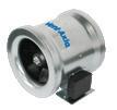
Vent-Axia has designed a complete range of energy efficient Mixed Flow In-Line fans that are now quieter, offer two and half times the pressure of conventional axial fans and are dimensionally more compact making them ideal for many ducted applications.

The ACM Mixed Flow In-Line fan can operate in both horizontal and vertical positions.
Motor
All motors have three speeds selectable on installation and are fitted with Standard Thermal Overload Protection (S.T.O.P.). Designed for ambient temperatures up to +50°C. All sizes with capacitor run motors. All sizes are Class II appliances. Supply voltage 220-240V/1/50Hz.
Installation
These units have a separate footplate for simple location mounting and detachable spigots for simple connection to ducting. The motor body chassis rotates to provide connection in acute spaces. Cleaning the product is simple as all parts can be removed without removing the ducting.
Controller
For optimum variable speed performance use a Vent-Axia 1.5 Amp electronic controller. Surface mounted providing variable speed control with an On/Off/sensor slider with indication light. There is an adjustable minimum speed setting. The controller has electrical connections for use with suitable external sensors. Cannot be used with timer models.
1.5 Amp Controller (Suitable for 100mm – 200mm models). Dimensions: 86 x 156 x 53mm (H x W x D).
For flush fitting, a metal wall box accessory is available.
Hole for wall box: 80 x 150 x 150mm (H x W x D).
• Available in two sizes
• Supplied complete for simple installation
• Optimise fan performance by using an approved Vent-Axia controller
• Diagonal impeller with stator
• Galvanized metal housing
• Integrated thermal switch
• Includes a mounting bracket
• Designed to meet IP54
Ducted Ventilation
Vent-Axia has designed a complete range of energy efficient Mixed Flow In-Line fans for use with rigid and flexible ducting.
In-line Mixed Flow fans offer two and half times the pressure of conventional axial fans and are dimensionally more compact making them ideal for many ducted applications.

The ACM Mixed Flow In-Line fan can operate in both horizontal and vertical positions and can be mounted to meet its optimum performance.
Motor
All motors are fitted with Standard Thermal Overload Protection (S.T.O.P.). Designed for ambient temperatures up to +50°C. All sizes with capacitor run motors. ACM 250 and 315 are Class I appliances. Supply voltage 220-240V/1/50Hz.
ACM315 Controller
The electronic infinitely variable fan speed controller allow you to manually adjust the speed of single phase AC fans by varying the motor voltage through phase angle control. The integrated switch enables or disables the motor.
Supply voltage: 230 VAC / 50—60 Hz
Regulated output: Umin—Us
Min. speed adjustment: 80—180 VAC
Unregulated output: 230VAC max 2.0A
Protection standard - Flush mounting: IP44*
Protection standard - Surface mounting: IP54*
Ambient conditions - Temperature: 0—40 °C
Ambient conditions - Rel. humidity: 5—95 % rH (non-condensing)
Maximum load - Rated max, current: 0.2 - 3.0A
*According to EN 60529
Model Stock Ref £Trade
3A Transformer Controller SC5030 228.76
ACM 250 Controller
For optimum performance use a Vent-Axia electronic controller. Surface mounted providing variable speed control with an On/Off/sensor slider with indication light. There is an adjustable minimum speed setting. The controller is radio suppressed to BS EN 55014 and electrical connections for use with suitable external sensors are provided.
1.5 Amp Controller – Suitable for 250mm model
Dimensions: 86 x 156 x 53mm (H x W x D).
System 3. Continuous Mechanical Extract Ventilation can be achieved using a single centralised extract unit such as the Sentinel Multivent ducted from ‘wet’ rooms (kitchen, bathroom, en-suite and WC) or by decentralised individual fans (dMEV) in the ‘wet’ rooms. The fans run continuously at near silent levels providing a simple and effective form of ventilation.

The Lo-Carbon dMEV/SELV unit meets the latest requirements of the Building Regulations Approved Document F 2010 for wholehouse system ventilation.


• Market leading efficiency
• Digital controls with display
• Fully adjustable trickle & boost airflow settings
• 100mm & 125mm model
• Recognised in SAP PCDB

• Constant volume
• Display showing airflow and system pressure
• Switched live connection for external switches/sensors
• IPX5 rated
• Multi--orientation grille
• NHBC Approved
• STAS Approved (Scotland)
• Airflow sensor models UKAS calibrated
Continuous running, constant volume dMEV range with switched live (LS) and innovative digital display and harmonised control platform. Quiet running and with high pressure development, the dMEV is best in class.
The unique patented display provides the calibrated installed airflow and pressure meaning that there is no need to test the installation with an airflow measuring device.

The constant volume technology automatically adjusts the speed of the fan to ensure the desired airflow is delivered. A silent high pressure axial impeller means Lo-Carbon dMEV can meet the requirements of many domestic installations without the need to use a traditional centrifugal fan.
A brand new control platform also provides fully adjustable airflow in 1l/s increments, meaning wholehouse rates can be achieved easily using fewer fans than is currently possible with any other dMEV product on the market.
A new 125mm dMEV fan is also available to further improve Dwelling Emission Rates (DER) by improving efficiency and lowering noise. The larger 125mm spigot also means there are almost no restrictions in terms of duct lengths and bends used in the system, when compared to a traditional 100mm axial fan. This means fewer fans are required to achieve wholehouse ventilation rates.
As can be seen below, an axial dMEV fan consumes a fraction of the energy of the equivalent centrifugal fan - drastically reducing DER.
Be confident that the dMEV is delivering the right performance with our innovative digital display showing the airflow and system pressure of the installed product.
Designed to offer a more relaxing environment to the homeowner, the Lo-Carbon dMEV features a delayed start option. This patented comfort control option is selectable at installation and allows the homeowner to enjoy a quiet, peaceful bathroom for up to 20 minutes before the Boost activates. Furthermore, if the light switch turns On and Off within 3 minutes, the Boost will not activate. No more disturbing the family if the bathroom light is turned on during the night.


Lo-Carbon NBR dMEVe & dMEVe HT
For kitchen, utility and bathroom/toilet applications, the continuous running H model incorporates an adjustable (40% - 90%) ambient response humidistat. The fan will increase the extract rate if the humidity rises above the point set at installation.
Fixed Speed Settings (3 boost speeds, 2 trickle speeds)
Fixed Speed Settings (2 boost speeds, 3 trickle speeds)
Continuous running dMEV available in two sizes. Humidity control models incorporate an adjustable (40% - 90%) ambient response humidistat. The fan will increase the extract rate if the humidity rises above the point set at installation. Variable speed options for trickle and boost, dependant on size for maximum control. Features a display prism, to allow users to see airflow being achieved without having to remove a grille.
The de-centralised mechanical extract ventilation unit shall be the NBR DMEV as manufactured by Vent-Axia, exact unit sizing and specification shall be in accordance with the particular specification.
The range should consist of IPX5 rated 100mm and 125mm sizes to meet the Building Regulations compliant design, extracting air from wet rooms (including kitchen and utility) via rigid, flexible ducting or throughwall applications with the fewest fans possible, supplied with a 7 year warranty.
The 100mm DMEV should have variable speed settings of 5-30 l/s on trickle and 6-35 l/s on boost, achieving a minimum noise level of 13 dB(A) at 3 metres. The 125mm DMEV should have variable speed settings of 9-30 l/s on trickle and 10-35 l/s on boost, achieving a minimum noise level of 12.9 dB(A) at 3 metres. All units shall be and independently 3rd party tested at the Sound Research Laboratory (SRL), tested to BS EN 13141-6.
The unit shall comprise a single high efficiency EC/DC motor to deliver specific fan powers as low as 0.12 w/l/s, as measured in accordance with the SAP PCDB test method and listed on the PCDB database.
The controls for the DMEV unit shall provide fully adjustable, continuous trickle and boost speeds, with the airflow being controlled in 1 l/s increments. The boost speed shall be activated via a switch live input or integral humidistat.
The unit shall include an integral humidity sensor with ambient and rapid response capability, which increases fan speed in proportion to the level of humidity detected. The unit shall also automatically raise the humidity threshold set point as temperature decreases in order to prevent unnecessary boosting due to background humidity levels.
The unit shall be able to be commissioned as a continuous running or intermittent fan according to the Building Regulations compliant design. The fan will have an in-built spirit level for ease of installation.
Commissioning of the fan in accordance with the Building regulations shall be achieved without the use of an airflow measuring device. The fan shall be provided with a UKAS calibrated, constant volume function with the flow rates displayed on the unit without having to remove the cover via the display prism.
• Building Regulations Approved Documents F and L compliant
• Continuous mechanical extract
• Recognised in SAP PCDB - Low SFP
• Discreet, tasteful styling
• IPX4 rated - IPX7 rated (SELV)
• dMEV Pressure detection device
• 5 year motor warranty
• Suitable for wall, ceiling, panel and window mounting
• SELV models supplied with remote transformer and suitable for ‘Zone 1’
Building Regulations Approved Document F gives examples of three main methods of ventilation. Continuous mechanical extract ventilation, can be achieved using a single centralised extract unit such as the Sentinel Multivent ducted to ‘wet’ rooms (kitchen, bathroom, en-suite and WC) or by decentralised individual fans, such as the Lo-Carbon Centra in the ‘wet’ rooms. The fans run continuously at near silent levels providing a simple and effective form of ventilation.
SELV (Safety Extra Low Voltage) is designed for areas where a fan can be installed within Zone 1 in a room where there is a fixed bath or shower. Ingress Protected (IP) to IPX7 Lo-Carbon Centra SELV can be fitted safely within the spray area. The separate transformer can be mounted away from the spray zone and out of reach from the bath or shower.
The Lo-Carbon Centra meets the latest requirements of the Building Regulations Approved Document F for wholehouse system ventilation and all models come with a 5 year motor warranty.
Selection of the two trickle flow rates (6l/s or 9l/s) is via a simple ‘jumper’ on the control board. Different methods are available for operating the 15 l/s boost speed from a simple switched live to integral humidistat. See individual models for further details.
The attractive and discreet styling of the Vent-Axia Lo-Carbon Centra will complement the décor of any new home while virtually silent operation ensures optimum ventilation is achieved without intrusive noise.
dMEV version recognised in SAP PCDB. Lo-Carbon Centra has a specific fan power of only 0.18 W/l/s in through-the-wall kitchen applications.
Lo-Carbon Centra dMEV
Auto speed selection at installation and suitable for bathrooms or kitchens. The integral air pressure sensor checks the airflow when first installed and also helps the fan to compensate for external wind pressure.
Lo-Carbon Centra T/SELV T (Timer)
Ideal for bathroom and toilet applications, this unit runs continuously on trickle setting and may be boosted by the switched live input which activates the timer (fixed 15 min on T models, adjustable 5-30 minutes on SELV models).

Lo-Carbon Centra TP/SELV TP (Timer/Pullcord)
For bathroom/toilet applications, the continuous running TP model is boosted by the pullcord which activates the timer (fixed 15 min on TP models, adjustable 5-30 minutes on SELV models).
Lo-Carbon Centra HT/SELV HT (Humidistat/Timer)
For bathroom/toilet applications, the continuous running HT model is automatically boosted by the built-in humidistat or by a switched live input which activates the timer (fixed 15 min on HP models, adjustable 5-30 minutes on SELV models).
Lo-Carbon Centra HTP/SELV HTP (Humidistat/Timer/Pullcord)
For bathroom/toilet applications, the continuous running HTP model is automatically boosted by the built-in humidistat or by the pullcord which activates the timer (fixed 15 min on HTP models, adjustable 5-30 minutes on SELV models).
• Meets current Building Regulations Approved Document F & L for intermittent or continuous use
• Recognised in SAP PCDB - Low SFP on PCDB 0.38 W/l/s
• 100mm circular spigot for easy installation and replacement of any existing fan - flush or surface mount
• Filterless technology and maintenance free
• Lo-Carbon motors offering 90% energy savings and long life
• Motor cassette cartridge for simple replacement
• 5 year Motor Warranty
• IPX4 rated
• Suitable for wall, ceiling and panel mounting
The Lo-Carbon Quadra offers a single fan suitable for surface or flush mounting. Low speed selectable between 6, 9 and 12l/s and high between 15, 30 and 60l/s all with through the wall or two ducted selections to ensure installed performance is met.
With discrete aesthetics and low noise levels due to an accurately balanced impeller, it is also one of the most unobtrusive centrifugal kitchen fans available. The front cover design also provides no area for dirt to build up so it stays looking better for longer.
Lo-Carbon Quadra TP (Timer/Pullcord)
Dual speed: continuous running or intermittent to high speed. High speed via pullcord (On/Off) or switch live (with overrun timer).
Model Stock Ref
TP 439251
Lo-Carbon Quadra HTP (Humidistat/Timer/Pullcord)
Dual speed: continuous running or intermittent to high speed. High speed via integral pullcord (On/Off), integral adjustable humidity sensor or switch live (with overrun timer). When humidity sensor is triggered the flow rate increases proportionally with %RH to 50% of the set Boost speed.

Lo-Carbon Quadra TM (Timer/PIR)
Dual speed: continuous running or intermittent to high speed. High speed via integral PIR sensor or switch live (both with overrun timer). Model Stock Ref
• Reduces your carbon footprint
• Recognised in SAP PCDB
• Specific fan power as low as 0.16 W/l/s
• Suitable for use with external sensors and controllers
• Wireless control option for “X” models

• Complies with Building Regulations ADF and ADL
• Manufactured in the UK
Sentinel Multivent continuous mechanical extract ventilation, MEV is designed for the simultaneous ventilation of separate areas in the home or as a multipoint extraction system for a wide range of commercial applications. The units can be wall, ceiling or loft mounted. Where the ambient air has a high humidity content condensate drains are provided.
• Practical advice on product selection and installation
• Guidance on solutions to meet legislation requirements
• Project management and site deliveries
• After sales support and maintenance information
Sentinel Multivent has been designed to meet the exacting demands of developers, installers and users offering advanced control options and easier installation and commissioning.
• Demand Control - enables precise ventilation rate, is set in 1% increments based on property size
• Comfort mode allows homeowners to control when the unit runs and for how long to avoid disturbance
• Integral digital display allows the installer to select appropriate low, normal, boost and purge speeds to meet demand
• Manual and automatic control options
• Integral adjustable overrun timer and delay on timer
• Switched live and SELV connections
• Optional Wireless Control on “X” units
• Energy efficient EC/DC motors - 1/3 less energy lost to heat than a conventional AC motor
• Low Specific Fan Power (SFP) making it one of the most efficient products on the market
• Meets Building Regulations Approved Document F (System 3)
• Recognised in SAP PCDB up to kitchen + 6 wet rooms
• Meets carbon footprint reduction targets
• The need for better health: Removal of pollutants such as moisture, carbon dioxide and external fumes are all important factors
in maintaining indoor air quality, helping to create a healthier living environment
• The integral humidity sensor (Sentinel Multivent H) increases fan speed in proportion to relative humidity levels, saving energy and reducing noise
• The sensor also reacts to small but rapid increases in humidity, even if the normal trigger threshold is not reached. This unique feature ensures adequate ventilation, even for the smallest wet room
• Night time relative humidity increment setback feature suppresses nuisance tripping as humidity gradually increases with falling temperature
In order to make the right choice, developers and contractors should refer to Building Regulations ADL1a, SAP 2012 and SAP PCDB.
SAP PCDB was launched in June 2006 to reward innovative ventilation manufacturers by testing and listing energy efficient products that assist in helping developers meet their Target Emission Rates (TER).
SAP is the underpinning methodology behind the Energy Performance Certificates and is used to demonstrate compliance with Building Regulations for Dwellings - Approved Document L (England and Wales), Section 6 (Scotland) and Approved Document F (Northern Ireland). SAP PCDB specifically relates to wholehouse ventilation systems and lists a number of Vent-Axia Mechanical Ventilation solutions which offer an improved SAP rating over and above the default for these product types.
Dimensions (mm)


To assist developers and contractors Vent-Axia can provide detailed scheme designs together with installation guidance and training.
Carbon footprint is a measure of the amount of carbon dioxide (CO2) emitted through the burning of fossil fuels. From a residential and commercial building perspective, it is the amount of carbon generated when you consume a kiloWatt (kW) of electricity. Reducing a building’s carbon footprint will ultimately reduce electricity bills and save money for every individual household or business. It will also help meet the UK target for the reduction of emissions, as well as allowing you to help the environment.
See page D:10 for control options.
Tested according to BS EN 13141-6:2010. Breakout quoted spherical. Extract quoted hemispherical.
Octave Band (Hz) Sound Power Levels, dB
Tested according to BS EN 13141-6:2010. Breakout quoted spherical. Extract quoted hemispherical.
Sentinel Multivent can be used with a wide range of Vent-Axia controllers and sensors. Ranging from integral humidistats, through to wireless controllers to wired remote sensors.
Ambient Response Humidity Sensor
• Pullcord override and indication light
• Changeover relay switch
• Operating range: 30% - 90%RH
• Ambient operating temp. 5°C to 40°C
• 220-240V AC
• Will fit single gang box for surface mounting
Ecotronic Humidity Sensor

• Set point adjustable
• Maximum switching load 1 Amp inductive

• Pullcord override indicator
• Ambient operating temp. 0°C to 40°C
• Supply voltage 220-240V
Visonex PIR Sensor

• Fits any UK single gang mounting box
• Adjustable timer overrun (5-25 mins)
• Range of detection up to 10 metres
• Designed to meet IP43
• Ambient operating temp. range 0°C to 50°C
Air Quality Sensor
• Ambient operating temp. 0°C to 50°C
• DEMKO approved
• Surface mounted
• 1 - 25 min O/R timer
• Supply voltage 220-240V

• Recognised in SAP PCDB with best in class Specific Fan Power

• Reduces your carbon footprint
• Fitted with three 125mm or nine 90mm diameter extract spigots allowing quick connection to ducts

• Complies with Building Regulations ADF
• Option of wall, ceiling and loft mounting
• Improved controllability
• Two Switched Live connections
• Fully variable normal, purge and boost speeds
• Ultra quiet
• Integral humidistat (H version)
With growing concerns about accurate ventilation of properties, the Lo-Carbon Multivent MVDC range offers the option of ‘Close Control’ both in the residential and the commercial sectors. With a DC motor the multi speed Lo-Carbon Multivent is one of the most efficient central extract units available.
The units have 3 fully variable speeds: normal, boost and purge. The digital display allows accurate setting of airflow, ensuring exactly the right ventilation rate. Accurate speed control helps minimise noise and energy consumption.
The Multivent H version incorporates a built-in humidity sensor to boost the unit when humidity reaches a certain threshold.

MVDC-MSH features an integral humidistat which triggers the unit to boost when humidity levels in the duct system exceed 70%.

Vent-Axia offers a complete range of Mechanical Ventilation with Heat Recovery (MVHR) units for residential and commercial applications, including many that are recognised in the SAP Product Characteristics Database.


Lo-Carbon
The latest flagship mechanical ventilation with heat recovery system. Designed and developed in the UK, it offers the highest level of comfort and functionality all year round.
Introducing a full range of products, with air performance suitable for all types of homes. Our new Sentinel-X controls platform delivers complete control over your ventilation environment. Provided through a full range of wired/wireless sensors and smartphone app.


• Manufactured in the UK
• Building Regulations ADF and ADL compliant
• Recognised in SAP PCDB
• Specific Fan Power down to 0.4 W/l/s
• Up to 94% heat recovery
• Fully automatic Summer bypass
• Horizontal and/or vertical duct outlets
• Integrated digital controller for simple and accurate commissioning
• Lightweight for easy installation
• External condensate connection
• Plug and play controls; Humidistat, Wireless Remote
• Acoustic Enclosure option for reduced breakout noise
• Acoustic Top Box option for reduced in-duct noise
The Sentinel Kinetic Range Incorporates:
• A wholehouse heat recovery system with up to 94% energy efficiency
• An easily accessible heat recovery cell protected by two removable ISO 45% Coarse (G3) filters
• Two Lo-Carbon energy saving EC/DC fans which ensure long life (typically over double the life of AC motors) and lowest possible energy use
• Fully insulated construction with built-in condensation drain
• Specifically designed for new build constructions with a high level of insulation
The Lo-Carbon Sentinel Kinetic meets the latest requirements of the Building Regulations ADF and ADL for wholehouse system ventilation: Continuous mechanical supply and extract with heat recovery. The Lo-Carbon Sentinel Kinetic models have 3 fully adjustable speeds and a purge setting (maximum flow). Provided with the unit is a digital controller that can be used to preset the speeds to any required airflow within the performance range.
The integral humidity sensor (models with H suffix) increases speed in proportion to relative humidity levels, saving energy and reducing noise. The sensor also reacts to small but rapid increases in humidity, even if the normal trigger threshold is not reached. This unique feature ensures adequate ventilation, even for the smallest wet room. The night time relative humidity setback feature suppresses nuisance tripping as humidity gradually increases with falling temperature.
For scenarios where noise is a critical issue, The Sentinel Kinetic Acoustic Solution is also available for all Sentinel Kinetic units. An Acoustic Enclosure will reduce breakout noise and the Acoustic Top Box will reduce in-duct noise at key frequencies. The acoustic solution sound data for each product can be found on the relevant product page.

A new ISO filtration standard has come into force. The test method has changed so direct comparisons between EN779 2012 and ISO 16890 cannot be drawn. Below is a guide to the filter efficiencies:
ISO 16890 EN779
45% Coarse G3
65% Coarse G4
ePM10 50% M5
ePM2.5 70% F7
For sensors see Accessories & Controllers section.
The Sentinel controller is the most advanced system available, providing Demand Control Ventilation (DCV), minimising energy consumption and noise levels, and optimising ventilation performance. Sentinel controlled units may be set to operate fully automatically or with varying levels of manual intervention.
There are two levels of BMS available: Basic Output and full Electronic BMS.
Basic Output provides a 5 volt output from the LED terminals on the controller. This output occurs whenever a message appears in the digital display, for example; ‘Check Filters’ or a fault code. The output can also be converted to volt-free with the addition of an optional Opto-Coupler.
Electronic BMS: A full range of two-way digital signals are available through the RJ11 connector on the control board. The BMS system provider will translate this signal to extract the desired data. Contact Vent-Axia to discuss your specific requirements.
MVHR units are often installed in lofts or other locations where they are difficult to monitor. The optional remote LED alarm illuminates when any message is visible in the MVHR unit display panel. The LED alarm can be installed in a convenient location within the dwelling allowing end users to see that the unit requires attention.
Five volt-free pairs of switch terminals for sensor inputs allow boosting from a full range of Vent-Axia controllers – humidistats, PIR, timers.
Two terminals with 0-24V outputs allow 0V to 10V proportional control by sophisticated controllers such as CO2 sensors and proportional humidistats.
Switched-live for boosting via light switches (220-240V AC) or manual Normal/Boost switches. This connection has the advantage of Delay-On and Delay-Off facility. Delay-On enables you to prevent the Boost airflow between 0 and 10 minutes, after a light switch has been activated. DelayOff allows the Boost airflow to continue after a light switch is turned off to ensure effective clearance of humidity. This timer is adjustable between 0 and 25 minutes.
The units can be boosted incrementally via the on-board controller or the Wired Remote Controller: One press = 30 minutes, two presses = 60 minutes, three presses = continuous.
Frost Protection
In order to prevent frost forming inside the unit in winter conditions, the Kinetic range employs a sophisticated frost protection strategy that modifies the airflows ensuring heat recovery continues down to -20°C. Below this temperature, the units will operate as 'extract only' fans. If balanced ventilation is required at low temperatures, a duct pre-heater should be used.
Model Stock Ref
LED Alarm with 15 metre cable 448356
Wired Remote Controller with 15 metre cable 443283
The unit can be set to maximum flow (100%) by pressing and holding the Boost button on the unit itself or optional wired controller for 5 seconds. Purge will continue for two hours unless cancelled by pressing the Boost button again.
In addition, the Acoustic Purge Fan can be used in conjunction with a Sentinel Kinetic MVHR unit or independently via a separate switched live connection or 0-10V external sensor input.
Model Stock ref
Acoustic Purge Fan
Acoustic Purge Fan XL
Night-time Purge mode: As Evening Purge, except that the unit will continue on Boost speed until the internal air temperature reaches the 'Outdoor' temperature set point (Default 14°C). This mode gives pre-cooling of the dwelling for the following day.
In Evening and Night Time Purge modes, the user can turn off the boost function by pressing the Boost button.
A Summer Bypass can make a contribution to reducing internal temperatures but is not a substitute for appropriate design and construction.


System canopy hoods are a motorless hood with extract being provided by the MVHR unit. When the Boost button on the canopy is activated, the MVHR unit goes to boost setting and the summer bypass opens preventing cooking by-products entering the heat exchanger cell. SELV hoods allow the distance between the hood and an electric hob to be reduced from 650mm to 550mm.
Model Stock ref
477988
479829
An internal damper operates when the external temperature is below the internal temperature, and the internal temperature is too high.
The bypass opens and allows the cooler outside air to help cool the dwelling.
Normal mode: Fans run on Normal speed with bypass open until the internal dwelling temperature falls below the set 'Indoor' (maximum desired) temperature.
Evening Purge mode: The fans run on Boost speed until the internal temperature falls below the set 'Indoor' temperature. If, after five hours the internal temperature is still above the set 'Indoor' temperature, the unit will switch down to normal speed for the remainder of the 'bypass open' period.


The Lo-Carbon Sentinel Kinetic Range can be used with a wide range of optional Vent-Axia controllers and sensors. Ranging from integral humidistats, through wireless controllers to wired remote sensors.
Wired Remote Controller
• Standard with horizontal units, optional extra with vertical units
• Supplied with 15 metres of cable (max length), the Wired Remote Controller duplicates all the features of the on-board control panel, allowing commissioning, diagnosis and user control
• Flush mounting, suitable for a single gang pattress box 16mm

Normal Boost Switch with Light Indicator
• Single gang switch with LED illumination when in the Boost condition
• 85 x 85 x 10mm (H x W x D)
Normal Boost Switch - Stainless Steel
• A single gang switch to operate normal/boost functions on MVHR systems
• Brushed stainless steel finish
• 90 x 90 x 18 (H x W x D)
Ambient Response Humidity Sensor
• Pullcord override and neon indicator
• Changeover relay switch
• Operating range: 30% - 90%RH
• Ambient operating temp. 5°C to 40°C
• 220-240V AC
• Will fit single gang box for surface mounting
Ecotronic Humidity Sensor
• Set Point adjustable
• Maximum switching load 1 amp in-ductive

• Pullcord override indicator
• Ambient operating temp. 0°C to 40°C
• Supply voltage 220-240V
Air Quality Sensor
• Ambient operating temp. 0°C to 50°C
• Min - Max mode or direct damper control
• Surface mounted
• 1 - 25 min O/R timer
• Supply voltage 220-240V
Normal Boost Switch
• A single gang switch to boost from low to high speeds on heat recovery systems
• 85 x 85 x 10mm (H x W x D)
Visonex PIR Sensor
• Fits any UK single gang mounting box
• Adjustable timer overrun (5-25 mins)
• Range of detection up to 10 metres
• Designed to meet IP43
• Ambient operating temp. range 0°C to 50°C
Isolator Relay Controller
• Allows fan unit to be isolated from other mains circuit when used with trickle/boost switch or light switch control


Momentary Push Switch
• Compatible with Sentinel Kinetic range, the momentary switch boosts the unit for 30 minutes
• 85 x 85 x 10mm (H x W x D)
• Recognised in SAP PCDB
• Lightweight for easier installation
• Horizontal duct option for space-saving installations
• Fits within a 290mm deep kitchen cupboard
• Integrated digital controller for simple and accurate commissioning
• Plug and play controls; Humidistat, Wireless Remote
• BMS connectivity
• LS inputs (Light Switch)
• Horizontal duct options
• Acoustic Enclosure option for reduced breakout noise
• Acoustic Top Box option for reduced in-duct noise
The Sentinel Kinetic models can be mounted vertically in a roof space, hallway cupboard or kitchen or within a kitchen cupboard. When mounted in an unheated area ducting and MVHR unit should be insulated. Ducting can be attached to the unit horizontally, vertically or both. Minimum internal depth of kitchen cupboard 290mm.
For scenarios where noise is a critical issue, an Acoustic Enclosure is available to reduce breakout noise and the Acoustic Top Box will reduce in-duct noise at key frequencies.
Left (L) or right (R) hand installation. The unit is supplied with duct spigots to outside on the right hand side. These can be reversed on site by simply removing the control panel, rotating the unit 180 degrees and re-attaching the control panel.
The combination of spigot options allows installation in confined locations. If vertical and horizontal connection is required on the same outlet/inlet, additional spigots can be supplied.
The condensate drain can be taken out through the back, side or bottom of the unit. Using the fittings supplied, the final condensate connection is made outside the unit and can be completed after installation.

The integral humidity sensor increases speed in proportion to relative humidity levels, saving energy and reducing noise. The sensor also reacts to small but rapid increases in humidity, even if the normal trigger threshold is not reached. This unique feature ensures adequate ventilation, even for the smallest wet room. The night time relative humidity setback feature suppresses nuisance tripping as humidity gradually increases with falling temperature.
Performance
Fan speeds are fully adjustable within the performance range.
x figure relates to Wattage (both motors)
Tested according to BS EN 13141-7:2010. Breakout quoted spherical. Supply and Extract quoted hemispherical. For in-duct data, end reflections are added based on the spigot size of the unit.
The supply and extract ventilation unit shall be a Sentinel Kinetic as manufactured by Vent-Axia and shall be sized as indicated on the drawings and shall be in accordance with the particular specification.
Supply air to the room shall be pre-heated by the extract air via the integrated composite plastic counterflow heat recovery cell. The Sentinel Kinetic shall automatically vary the ventilation rate via EC/DC motors, as it receives signals from one of the optional interconnected sensors. When a signal is received, the fans shall either vary their speed proportionally or on a trickle and boost principle.
The unit shall have the facility to commission the supply and extract fans individually via in-built minimum and maximum speed adjustment, or alternative wired remote control unit. The fans themselves shall have independent, infinitely variable speed control.
The unit shall be manufactured with an ABS outer case construction, and incorporate a reversible core to allow for left or right hand mounting.
The unit shall have a high efficiency composite plastic counterflow heat exchanger, supply and extract filters, automatic summer bypass, integral minimum and maximum infinitely variable speed controls with facia mounted failure indication. The unit shall have low energy, high efficiency EC/DC fan/motor assemblies with sealed for life bearings. The impellers shall be high efficiency forward curved centrifugal type.
The unit shall have a heat exchanger cell with a thermal efficiency of up to 92% when tested to EN 308. This shall be protected by ISO 45% Coarse (G3) grade synthetic filters on supply and extract. Complete with a condensate drip tray and drain connection.
The unit shall be constructed with a removable Core allowing full maintenance access. The removable Core shall provide access to the following:
Supply and extract filter
Heat exchanger
Access to the electrical connections
To reduce breakout noise, the MVHR unit shall be provided with an Acoustic Enclosure of steel construction lined with class '0' acoustic foam. To reduce in-duct noise, the top of the MVHR shall be fitted with an Acoustic Top Box to provide attenuation to the 4 ducts of the unit. This Acoustic Top Box shall be of steel construction lined with acoustic class '0' foam with the MVHR spigots linked to the Top Box via 4 separate attenuated ducts. The acoustic enclosure and top box shall each be independently tested for noise to BS EN 13141-7.
The MVHR unit shall incorporate an Expanded Polystyrene (EPS) inner chassis with custom motor and impeller mounting features. The inner chassis will assist in reducing noise and act as a large anti-vibration mount avoiding transmission through to the back mounting plate or the base of the unit.
The MVHR unit shall be tested to ensure it meets the maximum allowable vibration of no more than 1mm/s, measured on the unit wall fixing points.
Access shall be provided for wiring termination and setup/commissioning. The backlit LCD user interface therein shall be removable for remote mounting if required.
Units shall be as manufactured by Vent-Axia Ltd.
Standard Controls
All Sentinel Kinetic units shall incorporate the following functions integrally mounted, pre-wired and factory fitted by the manufacturer:
Integral infinitely variable fan speed control on supply and extract
Integral min/max ventilation control/set point
Integral BMS interfaces – control and status indication
Heating interlocks
0-10V proportional speed adjustment
Volt free contacts
24V sensor supply
Integral on/off or trickle boost function from remote switch e.g. PIR occupancy detector
The unit shall be controlled by the ‘Sentinel’ control devices (enablers and sensors) as detailed in the schedule or on the drawings
Fully automatic summer bypass
Switched Live input with adjustable ‘delay-on’ feature
Fan failure or component failure indicated via individual fault code display
Running time counter
Control panel PIN number lock
Automatic frost protection effective to -20°C
Tool free filter access
The unit shall incorporate (‘H’ models) an integral humidity sensor with the following features:
• Ambient Response; Raises the humidity trigger point as dwelling temperature reduces
• Rapid Response; Monitors the rate of change in humidity and triggers increased airflow even if the humidity trigger threshold is not reached
• Proportional Response; Incrementally increases the fan speed to reduce noise and reduce energy consumption
Duct extract from dwelling (Yellow)
Acoustic duct (Optional) supply to dwelling (Red)
Electrical Connection
Insulated duct exhaust to atmosphere (Brown)
Insulated duct from atmosphere (Green)
Front (RH)
Insulated duct from atmosphere (Green)
Insulated duct exhaust to atmosphere (Brown)
Acoustic duct (Optional) supply to dwelling (Red)
Duct extract from dwelling (Yellow)
Front (LH)
Please note: Electrical connection should be carried out by an appropriately qualified person and in accordance with current wiring regulations.
• Acoustic Enclosure option for reduced breakout noise
• Acoustic Top Box option for reduced in-duct noise
• Lightweight for easier installation
• Horizontal duct option for space-saving installations
• Integrated digital controller for simple and accurate commissioning
• Plug and play controls; Humidistat, Wireless Remote
• BMS connectivity
• LS inputs (Light Switch)
• Volt-free inputs
• Self diagnosis for simplified fault finding
• Adjustable delay On/delay Off timer
The Sentinel Kinetic models can be mounted vertically in a roof space or in an appropriate cupboard within the dwelling. When mounted in an unheated area the ducting and unit must be insulated in accordance with the Domestic Ventilation Compliance Guide. Ducting can be attached to the unit horizontally, vertically or both.
For scenarios where noise is a critical issue, an Acoustic Enclosure is available to reduce breakout noise and the Acoustic Top Box will reduce in-duct noise at key frequencies.
Left (L) or right (R) hand installation. Left hand and right hand units are available.
The combination of spigot options allows installation in confined locations. If vertical and horizontal connection is required on the same outlet/inlet, additional spigots can be supplied.

The condensate drain can be taken out through the back, side or bottom of the unit. Using the fittings supplied, the final condensate connection is made outside the unit and can be completed after installation.
The integral humidity sensor increases speed in proportion to relative humidity levels, saving energy and reducing noise. The sensor also reacts to small but rapid increases in humidity, even if the normal trigger threshold is not reached. This unique feature ensures adequate ventilation, even for the smallest wet room. The night time relative humidity setback feature suppresses nuisance tripping as humidity gradually increases with falling temperature.
Fan speeds are fully adjustable within the performance range.
quoted hemispherical. For in-duct data, end reflections are added based on the spigot size of the unit.
The supply and extract ventilation unit shall be a Sentinel Kinetic as manufactured by Vent-Axia and shall be sized as indicated on the drawings and shall be in accordance with the particular specification.
Supply air to the room shall be pre-heated by the extract air via the integrated composite plastic counterflow heat recovery cell. The Sentinel Kinetic shall automatically vary the ventilation rate via EC/DC motors, as it receives signals from one of the optional interconnected sensors. When a signal is received, the fans shall either vary their speed proportionally or on a trickle and boost principle.
The unit shall have the facility to commission the supply and extract fans individually via in-built minimum and maximum speed adjustment, or alternative wired remote control unit. The fans themselves shall have independent, infinitely variable speed control.
The unit shall be manufactured with an ABS outer case construction, and incorporate a reversible core to allow for left or right hand mounting.
The unit shall have a high efficiency composite plastic counterflow heat exchanger, supply and extract filters, automatic summer bypass, integral minimum and maximum infinitely variable speed controls with facia mounted failure indication. The unit shall have low energy, high efficiency EC/DC fan/motor assemblies with sealed for life bearings. The impellers shall be high efficiency backward curved centrifugal type.
The unit shall have a heat exchanger cell with a thermal efficiency of up to 90% when tested to EN 308. This shall be protected by ISO 45% Coarse (G3) grade synthetic filters on supply and extract. Complete with a condensate drip tray and drain connection.
To reduce breakout noise, the MVHR unit shall be provided with an Acoustic Enclosure of steel construction lined with class '0' acoustic foam. To reduce in-duct noise, the top of the MVHR shall be fitted with an Acoustic Top Box to provide attenuation to the 4 ducts of the unit. This Acoustic Top Box shall be of steel construction lined with acoustic class '0' foam with the MVHR spigots linked to the Top Box via 4 separate attenuated ducts. The acoustic enclosure and top box shall each be independently tested for noise to BS EN 13141-7.
The MVHR unit shall incorporate an Expanded Polystyrene (EPS) inner chassis with custom motor and impeller mounting features. The inner chassis will assist in reducing noise and act as a large anti-vibration mount avoiding transmission through to the back mounting plate or base of the unit.
The MVHR unit will be tested to ensure it meets the maximum allowable vibration of no more than 1mm/s, measured on the unit wall fixing points.
The unit shall be constructed with a removable Core allowing full maintenance access. The removable Core shall provide access to the following:
Supply and extract filter
Heat exchanger
Access to the electrical connections
Access shall be provided for wiring termination and setup/commissioning. The backlit LCD user interface therein shall be removable for remote mounting if required.
Units shall be as manufactured by Vent-Axia Ltd.
Standard Controls
All Sentinel Kinetic units shall incorporate the following functions integrally mounted, pre-wired and factory fitted by the manufacturer:
Integral infinitely variable fan speed control on supply and extract
Integral min/max ventilation control/set point
Integral BMS interfaces – control and status indication
Heating interlocks
0-10V proportional speed adjustment
Volt free contacts
24V sensor supply
Integral on/off or trickle boost function from remote switch e.g. PIR occupancy detector
The unit shall be controlled by the ‘Sentinel’ control devices (enablers and sensors) as detailed in the schedule or on the drawings
Fully automatic summer bypass
Switched Live input with adjustable ‘delay-on’ feature
Fan failure or component failure indicated via individual fault code display
Running time counter
Control panel PIN number lock
Automatic frost protection effective to -20°C
Tool free filter access
The unit shall incorporate (‘H’ models) an integral humidity sensor with the following features:
• Ambient Response; Raises the humidity trigger point as dwelling temperature reduces
• Rapid Response; Monitors the rate of change in humidity and triggers increased airflow even if the humidity trigger threshold is not reached
• Proportional Response; Incrementally increases the fan speed to reduce noise and reduce energy consumption
Duct extract from dwelling (Yellow)
Acoustic duct (Optional) supply to dwelling (Red)
Insulated duct from atmosphere (Green)
Insulated duct exhaust to atmosphere (Brown)
Front (RH)
Insulated duct exhaust to atmosphere (Brown)
Insulated duct from atmosphere (Green)
Acoustic duct (Optional) supply to dwelling (Red)
Duct extract from dwelling (Yellow)
Please note: Electrical connection should be carried out by an appropriately qualified person and in accordance with current wiring regulations.
•Best in class SFP's and thermal efficiencies up to 93%
•Approved Document F aligned commissioning wizard
•New Sentinel-X wireless control platform
•Intelligent smart app control as standard
•Horizontal duct option for space-saving installations (M & L only)
•ISO ePM10 (M5) and ePM2.5 (F7) filtration options
•Sound levels as low as 15.5 dB(A) breakout -independently tested and verified by SRL
•Left/right handing via controls
•Developed and manufactured in the UK
•Acoustic enclosure and top box options (S only)
The Lo-Carbon Sentinel Econiq is Vent-Axia’s latest flagship mechanical ventilation with heat recovery system. Designed and developed in the UK, it offers the highest level of comfort and functionality all year round.


Introducing a full range of products, with air performance suitable for all types of homes, the new Sentinel-X wireless controls platform delivers complete control over the home environment, provided through a full range of wired/wireless sensors and a smartphone app.
The highly sculpted interior surfaces, designed using the latest CFD techniques, ensure airflows are maximised through the unit, minimising noise and energy use. This feature alone provides an experience, that will delight homeowners, providing the most discrete and highly efficient ventilation available.
The MVHR filter options offer numerous benefits, including improved indoor air quality by removing allergens and particulate matter. They maintain the system's energy efficiency, reduce heating and cooling costs, and enhance the overall longevity of the system. Additionally, they capture bacteria, viruses and VOCs, promoting a healthier living environment. Regular filter maintenance extends the system's lifespan and ensures uninterrupted operation.
Whatever the outside environment, the system can help improve the indoor air quality by filtering out impurities, with ISO 60% Coarse (G4) supplied as standard, which can filter out sand, fine hair and particles larger than 10μm. Additional filtration can be achieved with a selection of optional filters, such as ISO ePM10 (M5), which can filter pollen, stone dust and particles smaller or equal to 10μm and ISO ePM2.5 (F7), which can filter out mould spores, bacteria and particles smaller or equal to 2.5μm.
The various sensor options allow for flexible installation in individual rooms, supporting effective management of the air in the home. For example, a CO2 sensor located within a habitable room helps ensure a healthy and safe working environment. CO2 levels managed at less than 1000ppm
help promote cognitive function. A humidity sensor located in the bathroom detects high levels of moisture can support good indoor air quality.
The Lo-Carbon Sentinel Econiq is one of the quietest systems on the market, with a noise level as low as 15.5 dB(A). The range is designed with an integral acoustic enclosure, made of steel, foam and expanded polypropylene (EPP), minimising breakout noise. The highly efficient motors are mounted on anti-vibration mounts to ensure minimal vibration transmission.
The Vent-Axia Connect smartphone application allows a multitude of functions to be adjusted from the comfort of the sofa, available on iOS and Android.
With smartphone-compatible controls, the homeowner is in full control of their ventilation all year round. They have the flexibility to increase the ventilation rate during hot periods in the summer or reducing the speed to minimise running costs while away.
The Sentinel control logic built within the MVHR ensures the system operates optimally with automated functions such as frost protection and summer bypass, providing comfort in the home.
The integral humidity sensor increases speed in proportion to relative humidity levels, saving energy and reducing noise. The sensor also reacts to small but rapid increases in humidity, even if the normal trigger threshold is not reached. This unique feature ensures adequate ventilation, even for the smallest wet room. The nighttime relative humidity setback feature suppresses nuisance tripping as humidity gradually increases with falling temperatures.
Low-energy buildings typically have very low leakage rates (below 3m3/(h.m2) at 50Pa). This reduces the effectiveness of the standard frost protection strategy which imbalances the airflows.
The inclusion of horizontal spigots allows for flexible installation in tight spaces. It is possible to use both vertical and horizontal connections.
For more Controller & Sensor information go to page G:21


The supply and extract ventilation unit shall be the Lo-Carbon Sentinel Econiq S, M or L as manufactured by Vent-Axia and shall be sized as indicated on the drawings and shall be in accordance with the particular specification.
The unit shall be fully insulated for thermal and acoustic performance and shall incorporate a counterflow multi plate heat exchanger with an independently verified thermal efficiency of up to 93%. The heat exchanger shall be protected by ISO 60% Coarse (G4) Grade filters on intake and extract airflows, with the option of a pre-filter. The unit shall have the facility to accommodate ISO ePM10 (M5) and ePM2.5 (F7) filters. The filters shall be accessible via tool-free access doors. The heat exchanger, motors, summer bypass and all other serviceable parts shall be accessible through the front of the unit.
Supply air to the room shall be pre-heated by an optional pre-heater and the extract air via the integrated composite plastic counter-flow heat recovery cell. The Sentinel Econiq shall automatically vary the ventilation rate via EC/DC motors, as it receives signals from optional or in-built sensor inputs. When a signal is received, the fans shall either vary their speed proportionally or on a trickle/boost principle.
The unit shall have the facility to commission the supply and extract fans individually via in-built minimum and maximum speed adjustment, alternative wired remote-control unit or via a compatible smartphone using the Vent-Axia Connect application. The fans themselves shall have independent, infinitely variable speed control.
The unit shall be manufactured with an ABS Outer case construction, with the ability to alter the spigot configuration via the on board controller. The unit shall have a high-efficiency composite plastic counter-flow heat exchanger, supply, and extract filters (up to ISO ePM2.5 (F7)), automatic 100% summer bypass, integral minimum and maximum infinitely variable speed controls with facia mounted failure indication. The unit shall have low-energy, high-efficiency EC/DC fan/motor assemblies with sealed for life bearings. The impellers shall be high-efficiency backward curved centrifugal type, achieving an SFP as low as 0.38W/l/s (EN 308).
The unit shall have a heat exchanger cell with a thermal efficiency of up to 93% when tested to EN 308. This shall be protected by ISO 60% Coarse (G4) grade synthetic filters on supply and extract, with the option of ISO ePM10 (M5), ISO ePM2.5 (F7) or external carbon activated filters. The unit shall have two condensate drain outlets for handing to be defined onsite and during commissioning.
The unit shall have wireless control capability options, using RF868 connectivity, 802.11b/g/n Wi-Fi and Bluetooth low energy 4.2. The unit shall use RF868 to connect to a wide ecosystem of wireless sensors including but not limited to CO2, temperature, and relative humidity. The unit shall be able to engage Wi-Fi to connect to local devices and create a local area network to allow for a larger network to be created for commissioning. The unit shall have Bluetooth low energy 4.2 to allow connectivity onto compatible smartphone devices.
The unit shall be constructed with a removable tool-free front panel which gives access to the removable on-board controller and other accessories. The EPS panel can then be removed with 4 screws allowing full maintenance access. This shall provide access to the following:
Supply or extract fan
Heat exchanger
Access to the electrical connections
The MVHR unit shall incorporate an Expanded Polystyrene (EPS) inner chassis with custom motor and impeller mounting features. The inner chassis will assist in reducing noise and act as a large anti-vibration mount avoiding transmission through to the back mounting plate or the base of the unit. The MVHR unit shall be tested to ensure it meets the maximum allowable vibration of no more than 1mm/s, measured on the unit wall fixing points.
The MVHR unit will be tested to ensure it meets the maximum allowable vibration of no more than 1mm/s, measured on the unit wall fixing points. Access shall be provided for wiring termination and setup/commissioning. The unit can be supplied with either a backlit user interface or a blank plate, both of which shall be removable for remote mounting if required. Filters shall be accessed via the two filter drawers found near the top of the unit, the S shall have filter drawers and the M and L shall have filter caps.
Units shall be manufactured by Vent-Axia Ltd.
The Lo-Carbon Sentinel Econiq shall incorporate the following functions through a user interface fitted by the manufacturer or a paired smartphone with the Vent-Axia Connect application: -
Integral infinitely variable fan speed control on supply and extract.
6 speeds; 4 adjustable
Left or Right hand spigot configuration, programmable during commissioning
Tool free filter access
Integral BMS interfaces – control and status indication
Heating interlocks
24V external sensor supply, eg PIR sensor
0-10V proportional speed adjustment
Volt free contacts
Fully automatic summer bypass
Filter check facility
Control panel PIN number lock
The unit shall incorporate:
An integral humidity sensor with the following features: Ambient Response; Raises the humidity trigger point as dwelling temperature reduces.
Rapid Response: Monitors the rate of change in humidity and triggers increased airflow even if the humidity trigger threshold is not reached.
Proportional Response; incrementally increases the fan speed to reduce noise and reduce energy consumption.
RS485 connectivity – Long distance cabling to support multiple sensor connections.
RF868 connectivity – Radio reference 868 MHZ for multiple wireless sensors pairing Bluetooth low energy 4.2 – Enable pairing within compatible smartphone device
802.11b/g/n Wi-Fi – Enable localised access point or connect to the local area network using the Vent-Axia Connect application, via a compatible smartphone device
The unit shall incorporate an automatic 100% summer bypass damper which monitors internal and external temperatures to maintain the user comfort temperature (default 21°C) :
- ‘Evening Fresh’ turns the unit to maximum speed with the bypass operational for 2 hours or until the user comfort temperature is reached (default 21°C).
- ‘Night Time Fresh’ will run the unit at maximum speed with the bypass operational throughout the night or until the dwelling reaches minimum temperature (default 14°C).
Independently acoustically tested to BS EN 13141-7:2010
Dimensions (mm)
Sound Spectrum (Unit only)
Tested according to BS EN 13141-7:2010. Breakout quoted spherical. Supply and Extract quoted hemispherical. For in-duct data, end reflections are added based on the spigot size of the unit.
Dimensions (mm) (Sentinel Econiq M & L)
Sound Spectrum (Sentinel Econiq M)
Performance
Wall-mounted HMI Kit to suit Econiq models with full HMI Includes HMI Blank controller, HMI backplate and cable.
• Dimensions (H x W x D) (mm) 90 x 90 x 17
• 240V local power supply required
• Wireless range 20m closed/100m open
• RF 868MHz Wireless or RS485 Wired communication
• Compatible with standard single gang or surface mounted pattress box
Stock Ref 411628
0-10V – Internal Temperature and Humidity - Wired
A sensor that measures the Internal temperature and relative humidity levels within the room and communicates to the compatible system, using the 0-10V output.

• Dimensions (H x W x D) (mm) 90 x 90 x 17
• 24V Power supply required
• Temperature range 0~60°C
• Relative humidity range 0-90% RH
• Compatible with standard single gang or surface mounted pattress box
• Status LED indicator for pairing, health check, faults & air quality traffic light index
• 0-10V Wired Communication
Stock Ref 496428
0-10V C02, Temperature and Humidity - Wired
Room mounted CO2 sensor with 0-10V signal output powered by an external 24V supply.
• Dimensions (H x W x D) (mm) 90 x 90 x 17
• 24V Power supply required
• Temperature range 0~60°C
• Relative humidity range 0-90% RH
• CO2 range 0-2000PPM
• Compatible with standard single gang or surface mounted pattress box
• Status LED indicator for pairing, health check, faults & air quality traffic light index
• 0-10V Wired Communication
Stock Ref 496432
Battery - Internal Temperature and Humidity - Wireless
Room mounted humidity and temperature sensor for wired or wireless communication with a compatible system. Using an in-built RF 868 MHz (Wireless radio frequency), or RS485 (Wired connection) communication method whilst being powered by batteries.

• Dimensions (H x W x D) (mm) 60 x 60 x 22
• 2 x AAA Batteries
• Temperature range 0~60°C
• Relative humidity range 0-90% RH
• Wireless range 20m closed/100m open
• RF 868MHz Wireless or RS485 Wired communication
• Status LED indicator for pairing, health check and fault conditions
• Mounted using provided back plate
Stock Ref 496431
Battery - External Temperature and Humidity - Wireless
Externally mounted humidity and temperature sensor for wired or wireless communication with a compatible system. Using an in-built RF 868 MHz (Wireless radio frequency), or RS485 (Wired connection) communication method whilst being powered by batteries.

• Dimensions (H x W x D) (mm) 116 x 114 x 40
• 2 x AAA Batteries
• Temperature range -30~60°C
• Relative humidity range 0-90% RH
• Wireless range 20m closed/100m open
• RF 868MHz Wireless or RS485 Wired communication

• IP Rating - IP67
• Status LED indicator for pairing, health check and fault conditions
Stock Ref 496442
Battery – 4 Speed Switch with Temperature and Humidity - Wireless Room mounted Speed Switch for wireless communication with a compatible system. Using an in-built RF 868 MHz (Wireless radio frequency) communication whilst being powered by batteries.
• Dimensions (H x W x D) (mm) 90 x 90 x 17
• 2 x AAA Batteries
• Temperature range 0~60°C
• Relative humidity range 0-90% RH
• Wireless range 20m closed/100m open
• RF 868MHz Wireless
• Mounted using provided back plate or compatible with a standard single gang or surface mounted pattress box
• Status LED indicator for pairing, health check and fault conditions
• Available in Black or White, image for illustration only
240V - Internal Temperature and Humidity - Wireless
Room mounted humidity and temperature sensor for wired or wireless communication with a compatible system. Using an in-built RF 868 MHz (Wireless radio frequency), or RS485 (Wired connection) communication method whilst being powered by a local 240V supply.
• Dimensions (H x W x D) (mm) 90 x 90 x 17
• Power supply 240V
• Temperature range 0~60°C
• Relative humidity range 0-90% RH
• Wireless range 20m closed/100m open
• RF 868MHz Wireless or RS485 Wired communication
• Compatible with standard single gang or surface mounted pattress box
• Status LED indicator for pairing, health check, faults & air quality traffic light index
Stock Ref 496429
240V - C02, Temperature and Humidity - Wireless
Room mounted CO2 sensor for wired or wireless communication with a compatible system. Using an in-built RF 868 MHz (Wireless radio frequency), or RS485 (Wired connection) communication method whilst being powered by a local 240V supply.
• Dimensions (H x W x D) (mm) 90 x 90 x 17
• Power supply 240V
• Temperature range 0~60°C
• Relative humidity range 0-90% RH
• CO2 Range 0-2000 PPM
• Wireless range 20m closed/100m open
• RF 868MHz Wireless or RS485 Wired communication
• Compatible with standard single gang or surface mounted pattress box
• Status LED indicator for pairing, health check, faults & air quality traffic light index
Stock Ref 496433
240V - PIR Sensor - Wireless

Room mounted PIR sensor for wired or wireless communication with a compatible system. Using an in-built RF 868 MHz (Wireless radio frequency), or RS485 (Wired connection) communication method whilst being powered by a local 240V supply. Room mounted presence detector for min/max or on/off control. Wall or ceiling mounting.
• Dimensions (H x W x D) (mm) 90 x 90 x 17
• Power supply 240V
• 5-25min run on timer
• PIR Range 3m
• Compatible with standard single gang or surface mounted pattress box
• Wireless range 20m closed/100m open
• RF 868MHz Wireless or RS485 Wired communication
Stock Ref 496438
240V - AIM Alarm Interface Module including Temperature and Humidity - Wireless
Room mounted AIM for wired or wireless communication with a compatible system. Using an in-built RF 868 MHz (Wireless radio frequency), or RS485 (Wired connection) communication method whilst being powered by a local 240V supply.
• Dimensions (H x W x D) (mm) 90 x 90 x 17
• Power supply 240V
• Temperature range 0~60°C
• Relative humidity range 0-90% RH
• Wireless range 20m closed/100m open
• RF 868MHz Wireless or RS485 Wired communication
• Compatible with standard single gang or surface mounted pattress box
• Status LED indicator for pairing, health check and fault conditions
Stock Ref 496441
240V - 4 Speed Switch with Temperature and Humidity - Wireless Room mounted Speed Switch for wireless communication with a compatible system. Using an in-built RF 868 MHz (Wireless radio frequency) communication whilst being powered by a local 240V supply.

• Dimensions (H x W x D) (mm) 90 x 90 x 17
• Power Supply 240V
• Temperature range 0~60°C
• Relative humidity range 0-90% RH
• Wireless range 20m closed/100m open
• RF 868MHz Wireless
• Mounted using provided back plate or compatible with standard single gang or surface mounted pattress box
• Status LED indicator for pairing, health check and fault conditions
• Available in Black or White, image for illustration only Model Stock Ref
240V - 4 Speed Switch with Temperature and Humidity - Wired Room mounted Speed Switch for wired communication with a compatible system. Using an in-built RS485 communication method powered by a local 240V supply.
• Dimensions (H x W x D) (mm) 90 x 90 x 17
• Power Supply 240V
• Temperature range 0~60°C
• Relative humidity range 0-90% RH
• Mounted using provided back plate or compatible with standard single gang or surface mounted pattress box
• Status LED indicator for pairing, health check and fault conditions
• Available in Black or White, image for illustration only
• RS485 Wired Connection
• Acoustic Enclosure option for reduced breakout noise
• Acoustic Top Box option for reduced in-duct noise
• Recognised in SAP PCDB
• Horizontal duct option for space-saving installations
• High airflow, ideal for student accommodation clusters
• Unique folding filter for removal when access is restricted
• Integrated digital controller for simple and accurate commissioning
• Plug and play controls; Humidistat, Wireless Remote
• BMS connectivity
• LS inputs (Light Switch)
• Volt-free inputs
• Self diagnosis for simplified fault finding
• Adjustable delay On/delay Off timer
• 4 fully adjustable speeds and a purge setting
The Sentinel Kinetic Plus benefits from the latest high efficiency, backward curved impeller design, ensuring the lowest possible energy consumption, ultra quiet operation and an exceptional performance range covering small one bed apartments to the largest of houses.
For scenarios where noise is a critical issue, an Acoustic Enclosure is available to reduce breakout noise and the Acoustic Top Box will reduce in-duct noise at key frequencies.
The Sentinel Kinetic Plus is ideal for larger homes and multiple occupancy units such as care homes and student accommodation. Capable of 400m3/hr at 150Pa, the unit can extract from up to ten bathrooms and a communal kitchen while still achieving almost 90% heat recovery. The fully automatic capability of the Kinetic range means that adequate ventilation is always achieved.

The Kinetic’s BMS capability is also ideal for those commercial applications where landlords or property managers want to monitor and optimise building performance and maintenance. The Kinetic BMS can provide status information and its self diagnostics can report if any fault is found.
Spigots may be re-positioned to give horizontal connection or a combination of vertical and horizontal connection.
Optional 180mm/200mm spigots can simplify connection in commercial installations where larger diameter duct work has been used.
As many systems are placed within cupboards the unique filter design folds as you remove it to ensure easy access in restricted spaces.
The integral humidity sensor increases speed in proportion to relative humidity levels, saving energy and reducing noise. The sensor also reacts to small but rapid increases in humidity, even if the normal trigger threshold is not reached. This unique feature ensures adequate ventilation, even for the smallest wet room. The night time relative humidity setback feature suppresses nuisance tripping as humidity gradually increases with falling temperature.
Fan speeds are fully adjustable within the performance range.
Tested according to BS EN 13141-7:2010. Breakout quoted spherical. Supply and Extract quoted hemispherical. For in-duct data, end reflections are added based on the spigot size of the unit.
The supply and extract ventilation unit shall be as Sentinel Kinetic Plus as manufactured by Vent-Axia and shall be sized as indicated on the drawings and shall be in accordance with the particular specification.
Supply air to the room shall be pre-heated by the extract air via the integrated composite plastic counterflow heat recovery cell. The Sentinel Kinetic Plus shall automatically vary the ventilation rate via EC/DC motors, as it receives signals from one of the optional interconnected sensors.
When a signal is received, the fans shall either vary their speed proportionally or on a trickle and boost principle.
The unit shall have the facility to commission the supply and extract fans individually via in-built minimum and maximum speed adjustment, or alternative wired remote control unit. The fans themselves shall have independent, infinitely variable speed control.
The unit shall be manufactured with an ABS outer case construction, and incorporate a reversible core to allow for left or right hand mounting.
The unit shall have a high efficiency composite plastic counterflow heat exchanger, supply and extract filters, automatic summer bypass, integral minimum and maximum infinitely variable speed controls with facia mounted failure indication.
The unit shall have low energy, high efficiency EC/DC fan/motor assemblies with sealed for life bearings. The impellers shall be high efficiency backward curved centrifugal type.
The unit shall have a heat exchanger cell with a thermal efficiency of up to 92% when tested to EN 308. This shall be protected by ISO 45% Coarse (G3) grade synthetic filters on supply and extract. Complete with a condensate drip tray and drain connection.
To reduce breakout noise, the MVHR unit shall be provided with an Acoustic Enclosure of steel construction lined with class '0' acoustic foam. To reduce in-duct noise, the top of the MVHR shall be fitted with an Acoustic Top Box to provide attenuation to the 4 ducts of the unit. This Acoustic Top Box shall be of steel construction lined with acoustic class '0' foam with the MVHR spigots linked to the Top Box via 4 separate attenuated ducts. The acoustic enclosure and top box shall each be independently tested for noise to BS EN 13141-7.
The unit shall be constructed with a removable Core allowing full maintenance access. The removable Core shall provide access to the following:
Supply and extract filter
Heat exchanger
Access to the electrical connections
Access shall be provided for wiring termination and setup/commissioning. The backlit LCD user interface therein may be duplicated for remote mounting if required.
Units shall be as manufactured by Vent-Axia Ltd.
The MVHR unit shall incorporate an Expanded Polystyrene (EPS) inner chassis with custom motor and impeller mounting features. The inner chassis will assist in reducing noise and act as a large anti-vibration mount to avoid transmission through to the back mounting plate or the base of the unit.
The MVHR unit shall be tested to ensure it meets the maximum allowable vibration of no more than 1mm/s, measured on the unit wall fixing points.
Sound tested to BS EN 13141-7:2010
Standard Controls
All Sentinel Kinetic units shall incorporate the following functions integrally mounted, pre-wired and factory fitted by the manufacturer:
Integral infinitely variable fan speed control on supply and extract
Integral min/max ventilation control/set point
Integral BMS input/output interfaces – control and status indication
Heating interlocks
0-10V proportional speed adjustment
Volt free contacts
24V sensor supply
Integral on/off or trickle boost function from remote switch, e.g. PIR occupancy detector
Fully automatic summer bypass
Switched Live input with adjustable ‘delay-on’ feature
Fan failure or component failure indicated via individual fault code display
Running time counter
Control panel PIN number lock
Automatic frost protection effective to -20°C
The unit shall incorporate an integral humidity sensor with the following features:
• Ambient Response; Raises the humidity trigger point as dwelling temperature reduces
• Rapid Response: Monitors the rate of change in humidity and triggers increased airflow even if the humidity trigger threshold is not reached
• Proportional Response; Incrementally increases the fan speed to reduce noise and reduce energy consumption
The unit shall be controlled by the ‘Sentinel’ control devices (enablers and sensors) as detailed in the schedule or on the drawings.
Tool free filter access
Duct extract from dwelling (Yellow)
Acoustic duct (Optional) supply to dwelling (Red)
Electrical Connection
Insulated duct from atmosphere (Green)
Insulated duct exhaust to atmosphere (Brown)
Front (RH)
Insulated duct exhaust to atmosphere (Brown)
Insulated duct from atmosphere (Green)
Acoustic duct (Optional) supply to dwelling (Red)
Duct extract from dwelling (Yellow)
Front (LH)
Please note: Electrical connection should be carried out by an appropriately qualified person and in accordance with current wiring regulations.
Trickle to Boost by two lighting circuits or Trickle/Boost Switch
• Acoustic Enclosure option for reduced breakout noise
• Acoustic Top Box option for reduced in-duct noise
• Recognised in SAP PCDB
• 180mm/200mm spigots
• Horizontal duct option for space-saving installations
• High airflow, ideal for student accommodation clusters
• Unique folding filter for removal when access is restricted
• Integrated digital controller for simple and accurate commissioning
• Plug and play controls; Humidistat, Wireless Remote
• BMS connectivity
• LS inputs (Light Switch)
• Volt-free inputs
The Sentinel Kinetic High Flow benefits from the latest high efficiency, backward curved impeller design, ensuring the lowest possible energy consumption, and an exceptional performance range covering small one bed apartments to the largest of houses.
For scenarios where noise is a critical issue, an Acoustic Enclosure is available to reduce breakout noise and the Acoustic Top Box will reduce in-duct noise at key frequencies.
The Sentinel Kinetic High Flow is ideal for larger homes and multiple occupancy units such as care homes and student accommodation. Capable of 175l/s at 150Pa, the unit can extract from up to fourteen bathrooms and a communal kitchen while still achieving almost 90% heat recovery. The fully automatic capability of the Kinetic range means that adequate ventilation is always achieved.

The Kinetic’s BMS capability is also ideal for those commercial applications where landlords or property managers want to monitor and optimise building performance and maintenance. The Kinetic BMS can provide status information and its self diagnostics can report if any fault is found.
180mm/200mm Spigots may be re-positioned to give horizontal connection or a combination of vertical and horizontal connection.
As many systems are placed within cupboards the unique filter design folds as you remove it to ensure easy access in restricted spaces.
The integral humidity sensor increases speed in proportion to relative humidity levels, saving energy and reducing noise. The sensor also reacts to small but rapid increases in humidity, even if the normal trigger threshold is not reached. This unique feature ensures adequate ventilation, even for the smallest wet room. The night time relative humidity setback feature suppresses nuisance tripping as humidity gradually increases with falling temperature.
For further details, see Sentinel Kinetic Plus.
Tested according to BS EN 13141-7:2010. Breakout quoted spherical. Supply and Extract quoted hemispherical.
The supply and extract ventilation unit shall be as Sentinel Kinetic High Flow as manufactured by Vent-Axia and shall be sized as indicated on the drawings and shall be in accordance with the particular specification.
Supply air to the room shall be pre-heated by the extract air via the integrated composite plastic counterflow heat recovery cell. The Sentinel Kinetic High Flow shall automatically vary the ventilation rate via EC/DC motors, as it receives signals from one of the optional interconnected sensors.
When a signal is received, the fans shall either vary their speed proportionally or on a trickle and boost principle.
The unit shall have the facility to commission the supply and extract fans individually via in-built minimum and maximum speed adjustment, or alternative wired remote control unit. The fans themselves shall have independent, infinitely variable speed control.
The unit shall be manufactured with an ABS outer case construction, and incorporate a reversible core to allow for left or right hand mounting.
The unit shall have a high efficiency composite plastic counterflow heat exchanger, supply and extract filters, automatic summer bypass, integral minimum and maximum infinitely variable speed controls with facia mounted failure indication.
The unit shall have low energy, high efficiency EC/DC fan/motor assemblies with sealed for life bearings. The impellers shall be high efficiency backward curved centrifugal type.
The unit shall have a heat exchanger cell with a thermal efficiency of up to 92% when tested to EN 308. This shall be protected by ISO 45% Coarse (G3) grade synthetic filters on supply and extract. Complete with a condensate drip tray and drain connection.
To reduce breakout noise, the MVHR unit shall be provided with an Acoustic Enclosure of steel construction lined with class '0' acoustic foam. To reduce in-duct noise, the top of the MVHR shall be fitted with an Acoustic Top Box to provide attenuation to the 4 ducts of the unit. This Acoustic Top Box shall be of steel construction lined with acoustic class '0' foam with the MVHR spigots linked to the Top Box via 4 separate attenuated ducts. The acoustic enclosure and top box shall each be independently tested for noise to BS EN 13141-7.
The unit shall be constructed with a removable Core allowing full maintenance access. The removable Core shall provide access to the following:
Supply and extract filter
Heat exchanger
Access to the electrical connections
Access shall be provided for wiring termination and setup/commissioning. The backlit LCD user interface therein may be duplicated for remote mounting if required.
Units shall be as manufactured by Vent-Axia Ltd.
The MVHR unit shall incorporate an Expanded Polystyrene (EPS) inner chassis with custom motor and impeller mounting features. The inner chassis will assist in reducing noise and act as a large anti-vibration mount to avoid transmission through to the back mounting plate or the base of the unit.
The MVHR unit shall be tested to ensure it meets the maximum allowable vibration of no more than 1mm/s, measured on the unit wall fixing points.
Sound tested to BS EN 13141-7:2010
Standard Controls
All Sentinel Kinetic units shall incorporate the following functions integrally mounted, pre-wired and factory fitted by the manufacturer:
Integral infinitely variable fan speed control on supply and extract
Integral min/max ventilation control/set point
Integral BMS input/output interfaces – control and status indication
Heating interlocks
0-10V proportional speed adjustment
Volt free contacts
24V sensor supply
Integral on/off or trickle boost function from remote switch, e.g. PIR occupancy detector
Fully automatic summer bypass
Switched Live input with adjustable ‘delay-on’ feature
Fan failure or component failure indicated via individual fault code display
Running time counter
Control panel PIN number lock
Automatic frost protection effective to -20°C
The unit shall incorporate an integral humidity sensor with the following features:
• Ambient Response; Raises the humidity trigger point as dwelling temperature reduces
• Rapid Response: Monitors the rate of change in humidity and triggers increased airflow even if the humidity trigger threshold is not reached
• Proportional Response; Incrementally increases the fan speed to reduce noise and reduce energy consumption
The unit shall be controlled by the ‘Sentinel’ control devices (enablers and sensors) as detailed in the schedule or on the drawings.
Tool free filter access
Duct extract from dwelling (Yellow)
Acoustic duct (Optional) supply to dwelling (Red)
Electrical Connection
Insulated duct from atmosphere (Green)
Insulated duct exhaust to atmosphere (Brown)
Front (RH)
Insulated duct exhaust to atmosphere (Brown)
Insulated duct from atmosphere (Green)
Acoustic duct (Optional) supply to dwelling (Red)
Duct extract from dwelling (Yellow)
Front (LH)
Please note: Electrical connection should be carried out by an appropriately qualified person and in accordance with current wiring regulations.
Trickle to Boost by two lighting circuits or Trickle/Boost Switch
• Acoustic Top Box option for reduced in-duct noise
• Recognised in SAP PCDB

• Includes Cooker Hood Canopy
• Horizontal duct option for space-saving installations
• Fits within a 600mm wide aperture (300mm deep)
• Integrated digital controller for simple and accurate commissioning
• Plug and play controls; Humidistat, Wireless Remote
• BMS connectivity
• LS inputs (Light Switch)
• Volt-free inputs
• Self diagnosis for simplified fault finding
• Adjustable delay On/delay Off timer
Ducting can be attached to the unit horizontally, vertically or both. Minimum internal depth of kitchen cupboard: 300mm.
Horizontal and Vertical Spigots: The combination of spigot options allows installation in confined locations. If vertical and horizontal connection are required on the same outlet/inlet, additional spigots can be supplied.
The condensate connection can be taken through the rear of the unit or through the side of the unit into an adjacent cupboard prior to connection into pre-installed domestic waste water system.
The Sentinel Kinetic Cooker Hood is designed to fit in a 600mm wide aperture above a hob. The telescopic hood incorporates two flat removable metal grease filters, low energy light bulbs and is available with a White or Brushed Aluminium front trim.
The hood contains an integral fire damper in accordance with BRE Digest 398 and is connected to the heat recovery unit by a galvanised steel duct with access for cleaning. When the hood is opened, the heat recovery unit goes to boost speed and the summer bypass automatically opens to prevent cooking by-products entering the heat recovery cell. As an additional safety feature, the duct also contains a thermal cut-out fuse which turns off the MVHR unit in the event of excessive temperature in the airway. Cooker Hood units cannot be handed on-site and must be purchased as left hand (L) or right hand (R) models.
SELV cooker hoods allow the distance between the hood and an electric hob to be reduced from 650mm to 550mm.
The integral humidity (models with H suffix) sensor increases speed in proportion to relative humidity levels, saving energy and reducing noise. The sensor also reacts to small but rapid increases in humidity, even if
the normal trigger threshold is not reached. This unique feature ensures adequate ventilation, even for the smallest wet room. The night time relative humidity setback feature suppresses nuisance tripping as humidity gradually increases with falling temperature. Models
Lo-Carbon Sentinel Kinetic with summer bypass and humidity sensor.

Performance
Fan speeds are fully adjustable within the performance range.
Tested according to BS EN 13141-7:2010. Breakout quoted spherical. Supply and Extract quoted hemispherical. For in-duct data, end reflections are added based on the spigot size of the unit.
The supply and extract ventilation unit shall be a Sentinel Kinetic as manufactured by Vent-Axia and shall be sized as indicated on the drawings and shall be in accordance with the particular specification.
Supply air to the room shall be pre-heated by the extract air via the integrated composite plastic counterflow heat recovery cell. The Sentinel Kinetic shall automatically vary the ventilation rate via EC/DC motors, as it receives signals from one of the optional interconnected sensors. When a signal is received, the fans shall either vary their speed proportionally or on a trickle and boost principle.
The unit shall have the facility to commission the supply and extract fans individually via in-built minimum and maximum speed adjustment, or alternative wired remote control unit. The fans themselves shall have independent, infinitely variable speed control.
The unit shall be manufactured with an ABS outer case construction, and incorporate a metal duct to the cooker hood, intumescent fire damper and thermal switch, in accordance with BRE Digest 398.
The unit shall have a high efficiency composite plastic counterflow heat exchanger, supply and extract filters, automatic summer bypass, integral minimum and maximum infinitely variable speed controls with facia mounted failure indication. The unit shall have low energy, high efficiency EC/DC fan/motor assemblies with sealed for life bearings. The impellers shall be high efficiency forward curved centrifugal type.
The unit shall have a heat exchanger cell with a thermal efficiency of up to 92% when tested to EN 308. This shall be protected by ISO 45% Coarse (G3) Filter 2pk grade synthetic filters on supply and extract. Complete with a condensate drip tray and drain connection.
The unit shall be constructed with a removable Core allowing full maintenance access. The removable Core shall provide access to the following:
Supply and extract filter
Heat exchanger
Access to the electrical connections
Access shall be provided for wiring termination and setup/commissioning. The backlit LCD user interface therein shall be removable for remote mounting if required.
Units shall be as manufactured by Vent-Axia Ltd.
Sound tested to BS EN 13141-7:2010
All Sentinel Kinetic units shall incorporate the following functions integrally mounted, pre-wired and factory fitted by the manufacturer:
Integral infinitely variable fan speed control on supply and extract
Integral min/max ventilation control/set point
Integral BMS interfaces – control and status indication
Heating interlocks
0-10V proportional speed adjustment
Volt free contacts
24V sensor supply
Integral on/off or trickle boost function from remote switch e.g. PIR occupancy detector
The unit shall be controlled by the ‘Sentinel’ control devices (enablers and sensors) as detailed in the schedule or on the drawings
Fully automatic summer bypass
Switched Live input with adjustable ‘Delay-On’ feature
Fan failure or component failure indicated via individual fault code display
Running time counter
Control panel PIN number lock
Automatic frost protection effective to -20°C
Tool free filter access
The unit shall incorporate (‘H’ models) an integral humidity sensor with the following features:
• Ambient Response; Raises the humidity trigger point as dwelling temperature reduces
• Rapid Response; Monitors the rate of change in humidity and triggers increased airflow even if the humidity trigger threshold is not reached
• Proportional Response; Incrementally increases the fan speed to reduce noise and reduce energy consumption
The Sentinel Kinetic Cooker Hood shall consist of a telescopic Hood and galvanised steel duct connection to the MVHR Unit.
The Hood construction shall be of grey powder coated steel with Brushed Aluminium or White painted fascia.
The Hood shall trigger the MVHR unit to a pre-defined boost speed and open the summer bypass when opened, and shall have two low-energy lamps illuminating the hob top.
Filter shall be a flat metal grease filter, removable for cleaning.
The galvanised steel ductwork shall provide a continuous fire barrier between the Hood and the MVHR unit. It shall contain an Intumescent fire damper, thermal cut-out and volume balancing damper. The thermal cut-out shall switch off the MVHR unit at a pre-defined safety temperature.
The duct shall have an access panel for cleaning by the end-user.
Duct extract from dwelling (Yellow)
Acoustic duct (Optional) supply to dwelling (Red)
Front (RH)
Insulated duct from atmosphere (Green)
Insulated duct exhaust to atmosphere (Brown)
Insulated duct exhaust to atmosphere (Brown)
Insulated duct from atmosphere (Green)
Electrical Connection
Acoustic duct (Optional) supply to dwelling (Red)
Duct extract from dwelling (Yellow)
Front (LH)
Please note: Electrical connection should be carried out by an appropriately qualified person and in accordance with current wiring regulations.
• Manufactured in the UK
• Building Regulations ADF compliant
• Recognised in SAP PCDB
• Energy Savings Trust best practice compliant
• Up to 81% heat recovery whilst controlling condensation
• Programmable Summer bypass
• Digital controller for simple and accurate commissioning
• External condensate connection
• Plug and play controls; Humidistat, Wireless remote
• LS inputs (Light Switch)
• Volt-free inputs
• Self diagnosis for simplified fault finding
• Adjustable delay On/delay Off timer
The Sentinel Kinetic Horizontal Range
A wholehouse heat recovery system with up to 81% heat exchange efficiency. An easily accessible heat recovery cube protected by two removable ISO 45% Coarse (G3) Filter 2pk. Two Lo-Carbon Energy Saving EC/DC fans ensure long life (typically over double the life of AC motors) and lowest possible energy use. Fully insulated construction with built-in condensation drain. Specifically designed for new build constructions with a high level of insulation.

Lo-Carbon Sentinel Kinetic Horizontal meets the latest requirements of the Building Regulations ADF for wholehouse system ventilation: Continuous mechanical supply and extract with heat recovery. Each model has three fully adjustable speeds and a purge setting (maximum flow). Supplied with the unit is a digital controller that can be used to pre-set the speeds to any required airflow within the performance range.
The integral humidity sensor (‘H’ models) increases speed in proportion to relative humidity levels, saving energy and reducing noise. The sensor also reacts to small but rapid increases in humidity, even if the normal trigger threshold is not reached. This unique feature ensures adequate ventilation, even for the smallest wet room. The night time relative humidity setback feature suppresses nuisance tripping as humidity gradually increases with falling temperature. Acoustically lined - low noise levels from only 20dB(A) @ 3m.
Multiple Control Options:
Five Volt-free pairs of switch terminals for sensor inputs allow boosting from a full range of Vent-Axia controllers – humidistats, PIR, timers.
Two terminals with 0-24V outputs allow 0V to 10V proportional control by sophisticated controllers such as CO2 sensors and proportional humidistats.
Switch-live for boosting via light switches (220-240V AC) or manual Normal/ Boost switches. This connection has the advantage of Delay-On and DelayOff facility. Delay-On enables you to prevent the Boost airflow between 0 and 10 minutes after a light switch has been activated. Delay-Off allows the Boost airflow to continue after a light switch is turned off to ensure effective clearance of humidity. This timer is adjustable between 0 and 25 minutes.
Summer Bypass
An internal damper operates when the external temperature is below the internal temperature, and the internal temperature is too high.

The bypass opens and allows the cooler outside air to help cool the dwelling.
Normal mode: Fans run on Normal speed with bypass open until the internal dwelling temperature falls below the set 'Indoor' (maximum desired) temperature.
Evening Purge mode: The fans run on Boost speed until the internal temperature falls below the set 'Indoor' temperature. If, after five hours the internal temperature is still above the set 'Indoor' temperature, the unit will switch down to normal speed for the remainder of the 'bypass open' period.
Night-time Purge mode: As Evening Purge, except that the unit will continue on Boost speed until the internal air temperature reaches the 'Outdoor' temperature set point (Default 14°C). This mode gives pre-cooling of the dwelling for the following day.
In Evening and Night Time Purge modes, the user can turn off the boost function by pressing the Boost button.
Frost Protection
In cold climates there is a possibility of frost building up on the intake side of the heat exchanger. In order to prevent damage, the Kinetic reduces supply flow while maintaining extract flow at temperatures down to -20°C.
200ZMH - 26kg
*Galvanized steel outer case construction
Performance - 200ZH/ZMH/ZPH Model
Fan speeds are fully adjustable within the performance range.
Sound Data - 200ZH/ZMH Model
Tested according to BS 848. Breakout quoted spherical. Supply and extract quoted hemispherical.
Fan speeds are fully adjustable within the performance range.
Tested according to BS848. Breakout quoted spherical. Supply and Extract quoted hemispherical.
The supply and extract ventilation unit shall be as Sentinel Kinetic Z as manufactured by Vent-Axia and shall be sized as indicated on the drawings and shall be in accordance with the particular specification; 200Z – 200mm deep, 300Z – 300mm deep.
The Sentinel Kinetic Z shall automatically vary the ventilation rate via EC/ DC motors, as it receives signals from one of the optional interconnected sensors. When a signal is received, the fans shall either vary their speed proportionally or on a trickle and boost principle.
The unit shall have the facility to commission the supply and extract fans individually via the wired remote control unit. The fans themselves shall have independent, infinitely variable speed control.
Unit Specification (200Z/ZM, 300ZH)
The unit shall be manufactured with a galvanized steel outer case construction and shall have a high efficiency aluminium heat exchanger.
Unit Specification (200ZP)
The unit shall be manufactured with high density EPP case and shall have a high efficiency polymer heat exchanger.
The unit shall have supply and extract filters, automatic summer bypass, integral minimum and maximum infinitely variable speed controls with failure indication via the wired remote controller.
The unit shall have low energy, high efficiency EC/DC fan/motor assemblies with sealed for life bearings. The impellers shall be high efficiency backward curved centrifugal type.
The unit shall have a heat exchanger cell with a thermal efficiency of up to 81% when tested to EN 308. This shall be protected by ISO 45% Coarse (G3) Filter 2pk grade synthetic filters on supply and extract. Complete with a condensate drip tray and drain connection.
The unit shall be constructed with a removable access panel allowing full maintenance access from below. The removable panel shall provide access to the following:
Supply or extract fan
Supply and extract filter
Heat exchanger
Access to the electrical connections
Access shall be provided for wiring termination and setup/commissioning.
Sound tested to BS EN 13141-7:2010
Standard Controls
All Sentinel Kinetic Z units shall incorporate the following functions integrally mounted, pre-wired and factory fitted by the manufacturer:
Infinitely variable fan speed control on supply and extract
Min/max ventilation control/set point
Heating interlocks
0-10V proportional speed adjustment
Volt free contacts
24V sensor supply
On/off or trickle boost function from remote switch, e.g. PIR occupancy detector
The unit shall be controlled by the ‘Sentinel’ control devices (enablers and sensors) as detailed in the schedule or on the drawings
Fully automatic summer bypass
Switched Live input with adjustable ‘delay-on’ feature
Fan failure or component failure indicated via individual fault code display
Running time counter
Control panel PIN number lock
Automatic frost protection effective to -20°C
The unit shall incorporate (‘H’ models) an integral humidity sensor with the following features:
• Ambient Response: Raises the humidity trigger point as dwelling temperature reduces
• Rapid Response: Monitors the rate of change in humidity and triggers increased airflow even if the humidity trigger threshold is not reached
• Proportional Response: Incrementally increases the fan speed to reduce noise and reduce energy consumption
The unit shall be controlled by the ‘Sentinel’ control devices (enablers and sensors) as detailed in the schedule or on the drawings.
Airflow Direction
View from beneath (drawing for airflow demonstration only - not intended to be an accurate representation of the product)
Please note: Electrical connection should be carried out by an appropriately qualified person and in accordance with current wiring regulations.
Trickle to Boost by two lighting circuits or Trickle/Boost Switch
• Acoustic Enclosure option for reduced breakout noise
• Acoustic Top Box option for reduced in-duct noise
• Lightweight for easy installation
• Easy access filters
• External condensate connection
• Compatible with a range of controls: PIR, Humidistat
• Horizontal duct option for space-saving installations
• Up to 94% heat recovery

• Summer mode
• Manufactured in the UK
• Switched live inputs (Light switch control)
A wholehouse heat recovery system with up to 94% energy efficiency. An easily accessible heat recovery cube protected by two removable ISO 45% Coarse (G3) Filters. Two Lo-Carbon Energy Saving EC/DC fans ensure long life (typically over double the life of AC motors) and lowest possible energy use. Fully insulated construction with built-in condensation drain.
Lo-Carbon Kinetic Plus E meets the latest requirements of the Building Regulations Approved Document F for wholehouse system ventilation.
The Lo-Carbon Kinetic Plus E model has two adjustable speeds, normal and boost. On the front of the unit is the controller that can be used to preset the speeds to any required performance, up to 111l/s (400m3/hr) 150Pa. Offering ‘Close Control’ to prevent over ventilating. Acoustically lined - low noise levels from only 20dB(A) @ 3m.
For scenarios where noise is a critical issue, an Acoustic Enclosure is available to reduce breakout noise and the Acoustic Top Box will reduce in-duct noise at key frequencies.
Units are supplied right handed with duct spigots to outside on the right hand side. These can be reversed onsite by simply removing the control panel, rotating the unit 180 degrees and reattaching the control panel.
The combination of spigot options allows installation in confined locations. If vertical and horizontal connections are required on the same outlet/inlet, additional spigots can be supplied.
An LED on the control panel illuminates at 6 month intervals to remind users to check and clean the filters.
The Kinetic E range benefits from an automatic frost protection system to prevent the heat recovery cell freezing in very cold weather, while at the same time maintaining ventilation.
There are two LS (Switched Live) inputs allowing the unit to be connected to a number of sensors and controllers such as Timespan, Ambient Response Humidistat. One of the LS connections also benefits from a ‘Delay-On’ feature which prevents the unit boosting unnecessarily. Switching on the control panel allows activation of the Summer Mode.
Fan speeds are fully adjustable within the performance range.
Tested according to BS848. Breakout quoted spherical. Supply and Extract quoted hemispherical. For in-duct data, end reflections are added.
The supply and extract ventilation unit shall be as Kinetic Plus E as manufactured by Vent-Axia and shall be sized as indicated on the drawings and shall be in accordance with the particular specification.
Supply air to the room shall be pre-heated by the extract air via the integrated composite plastic counterflow heat recovery cell. The Kinetic Plus E shall automatically vary the ventilation rate via EC/DC motors, as it receives signals from one of the optional interconnected sensors. When a signal is received, the fans shall vary their speed on a trickle and boost principle. The unit shall have the facility to commission the supply and extract fans individually via in-built minimum and maximum speed adjustment. The fans themselves shall have independent, infinitely variable speed control.
The unit shall be manufactured with an ABS outer case construction, and incorporate a reversible core to allow for left or right hand mounting. The unit shall have a high efficiency composite plastic counterflow heat exchanger, supply and extract filters, integral minimum and maximum infinitely variable speed controls with facia mounted failure indication.
The unit shall have low energy, high efficiency EC/DC fan/motor assemblies with sealed for life bearings. The impellers shall be high efficiency backward curved centrifugal type. The unit shall have a heat exchanger cell with a thermal efficiency of up to 94% when tested to EN 308. This shall be protected by ISO 45% Coarse (G3) Filter 2pk grade synthetic filters on supply and extract. Complete with a condensate drip tray and drain connection.
To reduce breakout noise, the MVHR unit shall be provided with an Acoustic Enclosure of steel construction lined with class '0' acoustic foam. To reduce in-duct noise, the top of the MVHR shall be fitted with an Acoustic Top Box to provide attenuation to the 4 ducts of the unit. This Acoustic Top Box shall be of steel construction lined with acoustic class '0' foam with the MVHR spigots linked to the Top Box via 4 separate attenuated ducts. The acoustic enclosure and top box shall each be independently tested for noise to BS EN 13141-7.
The unit shall be constructed with a removable Core allowing full maintenance access. The removable Core shall provide access to the following:
Supply and extract filter
Heat exchanger
Access to the electrical connections
Access shall be provided for wiring termination and setup/commissioning.
Sound tested to BS EN 13141-7:2010
Standard Controls
All Kinetic Plus E units shall incorporate the following functions integrally mounted, pre-wired and factory fitted by the manufacturer:
Integral infinitely variable fan speed control on supply and extract
Integral min/max ventilation control/set point
Integral on/off or trickle boost function from remote switch, e.g. PIR occupancy detector
Switched Live input with adjustable ‘delay-on’ feature
Tool free filter access
Frost protection
LED 'filter check' indicator
Duct extract from dwelling (Yellow)
Acoustic duct (Optional) supply to dwelling (Red)
Electrical Connection
Insulated duct from atmosphere (Green)
Insulated duct exhaust to atmosphere (Brown)
Front (RH)
Insulated duct exhaust to atmosphere (Brown)
Insulated duct from atmosphere (Green)
Acoustic duct (Optional) supply to dwelling (Red)
Duct extract from dwelling (Yellow)
Front (LH)
The unit can be switched to boost by applying 230 V to the LS1 or LS2 inputs. Alternatively, the boost button on the control unit may be used. Mains Cable Connections
• Controls condensation and odours
• Eliminates mould growth
• Up to 70% heat recovery - saves energy
• Extremely quiet operation
• Two speed settings
• ERP exempt (<30W)
The HR100R and HR100RS are ideal for single bedrooms/bathroom applications situated in hotel rooms, nursing homes and residential care homes.
The HR100R features top access making it ideal for loft installations.
The HR100RS features bottom access for installation on the slab above a suspended ceiling.
The HR100R/RS is a self-contained heat recovery unit for mounting in lofts and suspended ceilings. The unit is supplied without controls to allow for the unit to be tailored to suit the individual requirements.

Compatible with standard 100mm ducting for connection to internal grilles and external cowl.
The unit comes fitted with a single 2-speed motor, and provides continuous low volume ventilation with a boost option. A variety of control devices are available for manual or automatic speed control.
An integral heat exchanger transfers heat from the outgoing stale air to the fresh air supply, raising the supply air temperature whilst at the same time reducing its relative humidity.
Up to 18l/s FID capacity. The unit provides superior control of condensation and odours, ideal for bathrooms or small internal rooms.
Top access - ideal in loft installations.
Normal Boost Switch
A single gang switch to boost from high to low speeds on all heat recovery systems. 85 x 85 x 10mm (H x W x D)
Bottom access - ideal for suspended ceilings.
• Heat recovery unit for smaller residential or commercial applications up to 180m2

• Up to 70% heat recovery
• Low power consumption
• Effective condensation control
• Summer mode
The Integra heat recovery unit has been specially designed to provide ventilation for flats or rooms in residential, commercial, educational or leisure applications. Balanced ventilation is achieved by using nominal 100mm diameter rigid ducting.
Using a high performance, polymeric heat exchange cube, together with two powerful fans, the Vent-Axia Integra achieves efficiencies of up to 70%.
The compact cube interleaves outgoing moist air with incoming fresh air, allowing the heat from one to warm the other without the two air streams mixing. Energy is saved on room heating, with no power being used by the cube itself.
Performance of Integra: Up to 49l/s FID. Ideal for installation in ceilings voids or cupboards.
The 150VA Transformer enables the selection of trickle settings to match dwelling volume.
Integra to be used with a 150VA Transformer for maximum controllability.
• Heat recovery unit for larger residential or commercial applications

• Up to 70% heat recovery
• Low power consumption
• Effective condensation control
• 3 speed control
• Summer mode
• EC motors
The Vent-Axia Integra Plus EC is designed for mounting in ceiling voids, lofts and above a suspended ceiling. Four 150mm spigots are provided for simple connection to insulated flexible or rigid ventilation ducting. The unit comes complete with a 22mm condensate outlet.
The Integra Plus EC incorporates two adjustable speeds and a Purge setting (full Speed).
Switching on the controller allows activation of the Summer Mode.
Tested according to BS848. Breakout quoted spherical. Supply and Extract quoted hemispherical.
• 3 unit sizes covering 500-2000m3/h
• Sentinel demand ventilation control
• Low energy EC/DC motors
• Internal or external mounting IPX4
• Up to 90% energy recovery cell
• Independently tested to EN 308
• Proportional or constant pressure control
• Performance tested to BS848 Parts 1 & 2
• Manufacture controlled to BS EN ISO 9001
Mini and Midi Models are manufactured with a frameless construction from single skinned Aluzinc panels, internally lined with 90kg/m3 high efficiency acoustic and thermally insulating foam (fire retardant to BS476 Part 7 Class 1 & Part 6 Class O). Aluzinc panels allow for all units to be mounted either internally or externally as standard (IPX4). An optional inlet cowl is available for roof mounting applications if required.
Maxi units are manufactured with an aluminium frame construction with double skinned Aluzinc panels fitted with 60kg/m3 thermal acoustic insulation.
The casing includes an inclined inlet and bellmouth entry which directs the incoming air to the impeller with minimal turbulence. The result is better air management through the unit, less noise, higher efficiency and an increased performance.

The housing is designed to be as compact as possible for concealed false ceiling applications and Sentinel Totus2 D-ERV, Demand Energy Recovery casings incorporate top and bottom access panels for maintenance (note Maxi unit is side access). Access panels are sized to enable single man maintenance.
All Sentinel Totus2 D-ERV units feature low energy, Class 1, EC/ DC external rotor motor and backward curved impeller assemblies specifically chosen for performance and non-overloading characteristics. The assembly is dynamically balanced to DIN ISO 1940 Grade 6.3. Ball bearings are greased for life. Insulation is Class ‘B’ (from -25°C to +60°C). All models incorporate internal electronic overload protection and soft start function.
All Sentinel Totus2 D-ERV units are complete as standard with G4 replaceable synthetic filters, complete with filter change warning. High grade F6 filters are available as an option.
Extensively tested to BS848 parts 1 & 2. Published dB(A) figures are free field sound pressure levels at 3m with spherical propagation at reference level of 2 x 10⁻⁵ Pa. The inlet/outlet sound power level spectra figures are dB with a reference of 10–12 watts.
Every Sentinel Totus2 D-ERV unit is fitted with integrated controls and a purpose designed common user interface controller incorporating a 16 character backlit alpha numerical 2 line display with 4 button membrane keypad for fan status and commissioning set up. As standard this is mounted behind a removable perspex viewing pane allowing commissioning without accessing the wiring compartment. The user interface can be removed and remotely fixed if required. The unit also incorporates an isolator that is suitable for fitting a locking device to prevent accidental operation.
Motors are single phase 230V +/- 10% / 50/60Hz / 1ph.

24V DC power is provided from the unit for powering the matched range of Sentinel Demand Ventilation switches and sensors.
Models
Sensor Control
Model Stock Ref
Mini TOTUS2MINI
Midi TOTUS2MIDI
Maxi TOTUS2MAXI
Constant Pressure
Model Stock Ref
Mini/CP TOTUS2MINI/CP
Midi/CP TOTUS2MIDI/CP
Maxi/CP TOTUS2MAXI/CP
F6 Filter
HVAC temperature and carbon dioxide room sensor for proportional ventilation control. Sensor will monitor both CO2 and temperature levels between the set points, the air flow rate following the higher of the 2 outputs.
24V DC SELV. 0 - 2000ppm CO2 working range. 0 - 50°C working range. Auto-calibrating NDIR CO2 absorption sensor. Dimensions: 100 x 84 x 25mm (H x W x D).
Stock Ref 433257 612.12
Sensor monitors CO2 level in extract ducts from conference areas, offices, theatres etc. In proportional control mode, air flow rate tracks the CO2 level to improve indoor air quality.
24V DC SELV. 0 - 2000ppm CO2 working range. Autocalibrating NDIR absorption sensor. Adjustable probe length. MAX. IP Rating 65. Dimensions: 80 x 80 x 38mm (H x W x D).
Stock Ref 433259 663.75
Vent-Axia PIR *
A wall or ceiling mounted presence detector for use with Sentinel Totus2 D-ERV. Can be used in MIN - MAX mode or for direct damper control.
Fits any UK single gang mounting box. Adjustable timer overrun (5-25 minutes). Range of detection up to 10 metres. Designed to meet IP43. Ambient operating temperature range 0°C to +50°C. Supply voltage 24V DC SELV.
Dimensions: 87 x 87 x 40mm (H x W x D).

Stock Ref 433162 120.08
Vent-Axia ThermoSwitch®


Automatically switches on fans on either a rise or fall in air temperature.

Used for Trickle/ Boost operation. Setting range: +6°C to +30°C. IP20 rated. Sealed sensing mechanism. Mounting direct on surface only. Dimensions: 80 x 104 x 36mm (H x W x D). Volt free switch connection to Sentinel Totus2 D-ERV, Demand Energy Recovery.
Stock Ref 563502 40.23
Power Supply *
For those situations where a separate 24V DC SELV supply source is required to power duct dampers. 24W output capacity.
Stock Ref 433193 43.06
Replacement filter for Sentinel Totus to grade F6. Replaces standard G4 filter.

Model Stock Ref £Trade Mini 445852 0.00
Midi 407882 0.00
Maxi 445946
PIR Grille*
PIR grille is on extract grille with an integral flap damper. Suitable for bathrooms and WCs. The PIR function fully opens the damper when a person presence is detected. The opening time is fixed at 20 mins. Spigot size is 125mm.
12V AC SELV unit using the main transformer unit supplied. Integral PIR person presence sensor controlling damper. Auto-humidity control damper response at all times. 100° viewing angle. Temperature range 0 - 50°C. Dimensions: 158 x 150 x 35mm (H x W x D). MAX airflow 70m3/hr @100 Pa.
Stock Ref 434184 252.49
Two types available:
a) MM type - opening shut/MIN to open/MAX controlled by switches and
b) PC type - opening proportionally when controlled by sensors.
Duct sizes available: 100, 125, 150, 200, 250 and 315. Industry standard actuators.

Typical ordering designation: DVD size MM or PC
For these situations where there is no ducted inlet or extract and the unit is roof mounted. Offers weather protection to ensuring air paths do not recirculate.
To convert rectangular duct spigot to 315mm dia circular ducting.

Stock Ref 449645 89.19
Top up heating LPHW coils to suit the duct connection size for each Totus. Sized to give 18 to 25°C temperature rise at maximum airflow with water 80/60 as standard. For full details contact Technical Support.
* PLEASE NOTE: These sensors/controls are unique to Sentinel Totus2 D-ERV and CANNOT be used with any other product.
• Models available with either a White or Brushed Aluminium trim
• Fits within a 600mm wide aperture (300mm deep)
• Complete with two low energy 9W lamps
• All models are fitted with a metal washable grease filter as standard
• 125mm galvanised duct connection piece
• Integral fire damper in accordance with BRE 398
• Weight: 3.7kg
The Pull-out System Hood is designed to fit in a 600mm aperture above a hob. The telescopic hood incorporates two flat removable metal grease filters, two low energy light bulbs and is available with a White or Brushed Aluminium front trim.
The hood contains an integral fire damper in accordance with BRE Digest 398 and is connected to the mechanical ventilation unit by a galvanised steel duct connection piece. When the hood is opened the mechanical ventilation unit goes to boost speed.

Steam created during the cooking process can cause moisture to form on walls and furniture. In extreme cases this can lead to mould growth. Strong smells can also be created during cooking and these can spread throughout the dwelling. Cooking oils may be vaporised when frying and this oil can be deposited in areas around the cooker.
When connected to an MEV or MVHR system, the Pull-out System Hood can be wired in such a way that when the hood part of the unit is pulled out the MEV or MVHR system will automatically switch to boost.
The Pull-out Hood System Hood comes with an integrated 125mm galvanised spigot to allow for connection to the MEV or MVHR system.
SELV hoods allow the distance between the hood and an electric hob to be reduced from 650mm to 550mm.
For controlling condensation, the Vent-Axia Lo-Carbon PoziDry and PoziDry Pro offer a quick and simple solution. A loft mounted positive input fan, the PoziDry Pro, draws fresh air from atmosphere, filters it and pushes it into the dwelling via a ceiling mounted diffuser. Stale air in the property is forced out through the natural forms of ventilation, such as window mounted trickle vents.

For those properties that do not have a loft, Lo-Carbon PoziDry Compact provides an easy to install solution. A duct mounted unit that can be fitted in a number of locations around a single floor flat or apartment.


• Anti-vibration joist mounting legs as standard
• Fully adjustable between 19l/s - 49l/s
• Smart SenseTM Technology offers simple control and data logging
• Uses latest Lo-Carbon motor technology for low running costs
• Ultra low sound level
• Complete with ceiling diffuser, flexible duct and G4 filters with F7 upgrade option

• IPX2 rated
• BBA Approved
Some parts of this product are made using recycled material therefore the colour of the plastic may vary from white to black. To find out more please visit www.vent-axia.com/sustainable
Designed to prevent and treat condensation and mould quickly. The BBA approved PoziDry ProTM is the perfect solution for general refurbishment, as its discreet, easy to install and almost silent running.
Lo-Carbon PoziDry ProTM offers a quick and simple solution. A loft mounted positive input fan draws fresh air from the loft, filters it and gently feeds it into the dwelling via a ceiling mounted diffuser. Clean, fresh filtered air with a lower moisture content dilutes, displaces and replaces, contaminated and moisture laden air.
The Lo-Carbon PoziDry ProTM is uniquely flexible in its installation methods, high sided anti-vibration legs and a hanging kit both come as standard, allowing the PoziDry ProTM to be installed quickly in any sized loft. The easy carry handle incorporated into the body makes carrying the unit easy and safe; especially useful when lifting the unit through loft hatches.
The unit is supplied with a purpose designed diffuser to be located over the stairwell of a conventional dwelling, in the main hall of a bungalow, in the landing or hallway. The 4-point contact easy fit technology allows fast and repeatable ‘drill free’ installation.
Using Smart SenseTM Technology the unit is easily set to the appropriate speed at installation based on the size of the dwelling. Natural leakage points that are present in all dwellings, as well as purpose provided exhaust points enhances the air change. En-suites and utility areas should be serviced by continuous mechanical extract ventilation.
The PoziDry ProTM can also be set to ‘Radon’ mode in properties that are affected by high radon gas levels. The unit will run continuously to ensure the constant supply of good indoor air to protect residents from harmful gases.
With a lightweight construction, the Lo-Carbon PoziDry ProTM features a specially developed Lo-Carbon DC fan/motor arrangement which runs quietly and delivers incredibly low running costs. The Lo-Carbon PoziDry ProTM uses a sensor to monitor the temperature in the loft, automatically adjusting the air volume when necessary. Additionally, resident comfort can be assured through an option to change the temperature at which the unit increases or decreases airflow. The unit will continuously ventilate silently in the background whilst in ‘Trickle’ mode. Once the unit automatically senses excess heat being lost into the loft the airflow will increase to ‘Energy Recovery’ mode to recover heat that would otherwise be lost through the roof. During summer months should the loft exceed 27°C (adjustable) the unit will enter ‘Stand-by’ mode in order stop the circulation of warm air allowing for a more comfortable living environment. PoziDry ProTM Heater models automatically turn on the 500W heater to help take the chill off the incoming air.
Standard filters supplied with the PoziDry ProTM are G4 (PM10 filtration) which filter out many every day pollutants such as pollen and dust. Optional F7 filters are available (PM2.5 filtration) removing tobacco smoke, diesel particulates, spores and a number of bacteria.
Smart SenseTM Technology allows the unit to record how long it has been running in each of its speeds. It also measures the number of days the product has been switched on to provide precise running information. Smart SenseTM Technology can also record the duration of heater activity and energy used.
Smart SenseTM Technology makes speed selection easy. Once house size is selected based on number of bedrooms, PoziDry ProTM automatically selects the correct ‘Trickle’ and ‘Energy Recovery’ speeds. Should you need to adjust speed manually this can be done easily. The Smart SenseTM interface can also be locked ensuring that settings are not tampered with.
The heater model comes with a 500W heater attached to the unit. Smart SenseTM controls allow the PoziDry ProTM to be adjusted fully when the heater is activated making it adaptable for all lifestyles.
This set is for air replacement through doors. Consists of a two-piece telescopic set, which fits unobtrusively on either side of the door panel. Minimum fixing thickness 30mm. Plastic. Dimensions: 454 x 90mm.
*Only required if there is not a 10mm undercut on the internal doors.
PoziDry ProTM comes as standard with both high sided anti-vibration legs and a hanging kit. The legs are designed to mount between standard joist widths between 300-650mm. Clip and fit connections allow for easy installation.
The electronically controlled DC motor is manufactured with long life ball bearings and is fitted with Standard Thermal Overload Protection (S.T.O.P.). Suitable for ambient operating temperatures of -25°C to +40°C. For complete peace of mind, the Vent-Axia Lo-Carbon PoziDry ProTM is backed by a 5 year warranty.
The discreet circular diffuser** is easily installed, fitted and maintained. Easy fix features it can be installed against uneven ceiling surfaces with no gaps. Its low profile and aesthetically pleasing design has been developed with tenant acceptability in mind. The Smart AirTM Technology reduces air supply noise while increasing performance by 10%. The easy clip blanking plates help to control airflow into the property.
**Diffuser will always be supplied using white plastic. Models
All models come with G4 filter, 2m of flexi duct and Ø200mm Diffuser. The Pozi Dry Pro TM FD model diffuser is fire rated but does not include Smart AirTM Technology.
An additional kit to allow an extra circular diffuser to be installed near the PoziDry unit. The kit includes 1 x Ø200mm
Duct, 2 x Worm Clips, 1 x Ø200mm Equal Y Piece and 1 x Diffuser.
• Ultra small unit can fit in the smallest of spaces
• Removable inner cartridge for easy repairs and maintenance
• Flow rates adjustable in 1l/s increments, up to 30l/s
• Extremely low energy consumption
• Washable, high capacity G4 or F7 filter
• Advanced data logger and 3 digit settings lock for peace of mind
• 7 year warranty
• Ideal solution for flats with mould in a habitable room

• BBA Approved
For those properties that do not have a loft, the Lo-Carbon PoziDry Compact Pro provides an easy to install solution. The unit has been designed to be as small as possible with multiple inlet and outlet positions allowing it to be installed in the best place every time.
Air is drawn into the Lo-Carbon PoziDry Compact Pro unit via an external inlet and through a short length of duct. The specially developed power pack cartridge assembly draws the air through an integral, high capacity, washable filter. The precision engineered scroll/impeller assembly and anti-vibration EPP body guarantees ultra low sound levels and increased energy efficiency.
The fresh, filtered airflow passes along the ducting and enters the room through a discreet grille. The rotatable integrated grille can be turned to one of 8 positions ensuring that the airflow is always directed upwards, reducing cold draughts.
The system provides fresh, tempered air into the home and creates an indoor environment where the damaging effects of condensation find it hard to exist, benefiting both the occupants and the structure of the building.
If the ambient temperature exceeds 27°C, the Lo-Carbon PoziDry Compact Pro will automatically switch off to prevent over-heating. This temperature threshold can be adjusted at installation.
In the case of the integral 300W heater version, the heater element is automatically activated when necessary and tempers the supply air to a chosen temperature.


Smart SenseTM technology records usage, energy consumption and filter life to ensure the unit has been used as intended. This is secured by an installer enabled 3 digit settings lock to make the PoziDry Compact Pro tamper free.
Dimensions (mm)
Performance Guide
* Sound data is measured as breakout @ 3m assuming inlet and outlet is ducted.

Since 1936, Vent-Axia has been known for providing a complete ventilation solution. This has not changed, and now we offer one of the widest ranges of ancillaries available today.


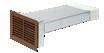


• “Telescopic” grille, providing flexibility during installation, accommodating variations is facade
• Built-in weather protection with angled grilles to promote run off
• Precautionary drainage holes
• Compliant with Approved Document B
• Compliant with Building (Scotland) Technical Handbook 2019
• Available in a choice of styles to suit new build and retrofit projects
Fire rated ductwork improves the safe operation of ventilation systems by minimising the chance of fire spread. Effective fire resilient insulation acts as a barrier between ducts, to slow down or prevent the passage of flames and smoke around the building.
A1 Fire-rated metal ducting kits, delivered as one piece, to allow for ease of installation, saving time on site. Perfect for multi-storey developments which require all materials forming part of the external wall to be made from non-combustible materials.
A1 Fire-rated ducting kit 204x60
A1 Fire-rated ducting kit 220x90


• One valve for air supply and extraction: suitable for up to 21l/s
• Easy to adjust: 26 lockable positions for setting the air volume
• Excellent performance: the lowest noise and pressure drop values
• Same appearance for each volume of air: external dimensions stay the same irrespective of the selected setting

• Low turbulence airflows: prevents accumulation of dirt around the valve
• Flexible installation for all types of air ducts with connection Ø116 or Ø125
• Easy to clean: no need to remove the valve base
• Multiple designs available to suit various interior styles
The Uniflexplus+ air distribution system has been designed to make installing and adjusting ventilation as quick and as easy as possible. With the Uniflexplus+ RV adjustable valve, the supply and extraction of air can be set and locked at fixed volumes in an instant.
The Uniflexplus+ RV is easy to install, even in suspended ceilings (with the aid of the special collar). The valve is also easy to maintain, as the base of the valve does not need to be removed from the ceiling. The air volume is adjusted entirely in the interior of the valve. This means that the external dimensions – and therefore the appearance – of the valves are always the same.

Uniflexplus+ is well known for its airtight connection without the use of mounting aids. Uniflexplus+ RV combines this with unique noise performance levels. Thanks to very low resistances, it is possible to meet the highest requirements in terms of comfort. If necessary, 120° of the supply/extraction opening can be blocked. In addition, the adjustable valve contains antistatic and antibacterial additives and is UV-resistant.
A great deal of attention has been devoted to the design of the adjustable valve and the materials used in it. It has an elegant appearance, with three different designs to suit various interior styles (RV 125, RVG 125 & RVV 125).


• Rapid local extract
• Satisfies Part F purge requirements
• Acoustically treated for low noise
• Helps to reduce overheating
• Can be used in conjunction with MVHR and MEV units or as standalone system
• 220x90 or 250 diameter spigots
• Low profile design
• Easy setup
• Energy efficient EC fan
• Variable speed control
• Low maintenance requirement
The Vent-Axia Acoustic Purge Fan is used to rapidly remove indoor pollutants as well as reducing the impact of overheating in residential dwellings, providing a more comfortable and healthy internal environment for home-owners.
The Acoustic Purge Fan can be used in conjunction with a Sentinel Kinetic MVHR unit or independently via a separate switched live connection or 0-10V external sensor input. The Acoustic Purge Fan can be installed in habitable rooms to satisfy Approved Document F Purge requirements (4 air changes per hour). The unit can be installed in conjunction with controllable duct dampers and/ or background ventilators to manage the supply air into the dwelling under purge operation.
The Acoustic Purge Fan is specially treated with acoustic foam to reduce breakout and induct noise, ensuring end-user comfort during operation. As well as boasting a low-profile design, the unit utilises 220x90 spigots to allow easy use of flat ducting in tight void spaces in apartments.

• Removes NOX and other gases
• Removes particles down to PM2.5
• Offers multiple spigot options
• Low pressure drop
• Easy to install with mounting brackets
• Conforms to international air quality guideline limits
• Easy installation & maintenance
• Various sizes to suit residential or commercial applications
• Provides induct noise attenuation
• Insulating jackets available
• New compact unit available
The Vent-Axia Pure Air combines particulate and gas filters to remove pollutants prior to entering residences and commercial buildings through mechanical ventilation and heat recovery systems. The Vent-Axia Pure Air is designed to bring outdoor air pollutant levels within the guideline exposure limits as set out in the World Health Organisation Air Quality Guidelines and the CAFE Directive prior to entering an occupied space.
Indoor air quality (IAQ) is becoming increasingly important with properties being built in urban, industrialised areas. The Vent-Axia Pure Air offers a complete filtration solution with a range of specifiable products that meet planning obligations and refine traditional filtration, leaving home owners with confidence in their heat recovery systems.
The Vent-Axia Pure Air sets the benchmark for high level filtration. It targets pollutants generated outside of the home, by traffic and industrial processes, and reduces these before supplying the air into the dwelling.
The Vent-Axia Pure Air filter is fitted to the intake airflow and incorporates two types of filtration:

• Enhanced activated Carbon which removes unpleasant odours and harmful gasses such as Nitrous Oxide (NO2).
• ISO 65% Coarse (G4) or ePM2.5 (F7) particulate filters which can remove tiny airborne contaminants such as pollen, bacteria and even PM2.5 diesel particulates.
The combination of MVHR and Vent-Axia Pure Air filtration offers the ideal indoor environment.
The Vent-Axia Pure Air is manufactured from 1.2mm Galvanised Steel together with suitable sealing for particulate and gas filters. Access is available on both sides via bolted lift off panels. Various round and rectangular transformation spigots are available to suit ductwork systems for both domestic and commercial duct work.


Particulates, PM10, PM2.5
A new ISO filtration standard has come into force. The test method has changed so direct comparisons between EN779 2012 and ISO 16890 cannot be drawn. Below is a guide to the filter efficiencies:
ISO 16890 EN779
45% Coarse G3
65% Coarse G4
ePM10 50% M5
ePM2.5 70% F7
Pollutant Gases, NO2, SO2, O3, VOC
The gas stage filters in the Vent-Axia Pure Air are designed to achieve a minimum contact time suitable for the removal of pollutant gases at the rated airflow. A specially formulated activated carbon and chemical mix acts upon pollutant concentrations common in dirty city air, reducing them below guidelines set by current legislation.
• Reduces induct noise
• Variety of sizes to suit specified noise requirements
• Compatible with both 204x60mm2 and 220x90mm2 rectangular ductwork

• Central and offset spigot options to suit each installation
• Rigid galvanized steel construction
• Easy installation
• Suitable for almost any ventilation system
• Low pressure loss
The Vent-Axia Wholehouse Attenuator has been developed to reduce induct noise in both residential and commercial ducting systems.
The Wholehouse Attenuator is compatible with either 204x60mm2 or 220x90mm2 ducting. It also offers two spigot options to suit the installation and design requirements. The Wholehouse Attenuator is available with either a standard centralised spigot or, for instances when the ducting is installed flat to a concrete slab, an offset spigot. As well as saving the need for additional ducting components, this allows for a much easier and quicker installation.
Noise Reduction
Offering excellent sound reduction over a range of frequencies, the Wholehouse Attenuator is available in two lengths depending on the noise suppression requirements. For MVHR systems the attenuator can be fitted on the supply side to habitable rooms, reducing airborne in-duct noise. For MVHR and extract-only systems, the attenuator may be placed on the extract side to limit ‘cross-talk’ through ductwork between rooms.
• Models available for both pitched and flat roof types
• Complies with Building Regulations
• Suitable for most installations
• Corrosion resistant and weather proof

• Compatible with both mechanical and natural ventilation systems
• Three colours available for pitched roof vents

Wholehouse ventilation systems require termination to the external atmosphere, often through the roof. To ensure that the ventilation system is able to achieve its optimum level of performance, it is important that a suitable roof termination product is installed.
With this in mind, Vent-Axia is pleased to offer a range of Universal Roof Vents; including products suitable for both pitched and flat roof types.

A selection of colours and sizes should ensure that our range offers a product suitable for most residential applications with a pitched or flat roof. Pitched roof vents are available in a variety of colours as detailed in the Specification Table - custom colour and textured vents to match your exact needs are also available at an extra charge. Please contact our Technical Support team for more details.
Universal Roof Vent suitable for Pitched Roofs Manufactured in the UK, these products have been specifically developed for use with both natural and mechanical ventilation systems.
All models have been independently tested by the BRE to BS476 Part 3: 2004 and have been awarded an AA classification - the highest possible. Thus they can be installed without restriction on any pitched roof.
All models have low resistances to airflow (see table) and incorporate condensation grooves to prevent any condensate running back down the duct. Universal Roof Vents are designed to resist the ingress of deluge and driving rain. Universal Roof Vents (pitched roof models) are suitable for roof pitches between 20° and 60°.
The pitched roof vents are available as a ‘tiled’ roof vent to fit alongside most traditional roof tiles, as well as a ‘slate’ version which can be easily cut down to fit alongside all traditional roof slates.
*Universal Roof Vents are not suitable for the following tile types: Plain, Clay Single Pantiles, Forticrete Centurion, Goxhill Gaelic Tiles, Double Lap or Interlocking Slates. If the Universal Roof Vent does not meet your requirements, please contact our Technical Support team for a bespoke solution
Universal Roof Vent suitable for Flat Roofs
Capped stacks for use in asphalt and built-up felt roofs. Special low air resistance cowl - the pressure/airflow resistance is <1.0 Pascal at 63l/s. The pipework above the roofline is twin walled and incorporates an integral condensation drain. The stack pipe has an integral collar and separate aluminium flange for use with both felt and asphalt roof finishes.
All Vent-Axia Universal Roof Vents have a free area exceeding those required by Building Regulations.

• Models available with either a White or Brushed Aluminium trim
• Fits within a 600mm wide aperture (300mm deep)
• Complete with two low energy 9W lamps
• All models are fitted with a metal washable grease filter as standard
• 125mm galvanised duct connection piece
• Integral fire damper in accordance with BRE 398
• Weight: 3.7kg
• SELV hoods allow the distance between the hood and an electric hob to be reduced from 650mm to 550mm
The Pull-out System Hood is designed to fit in a 600mm aperture above a hob. The telescopic hood incorporates two flat removable metal grease filters, two low energy light bulbs and is available with a White or Brushed Aluminium front trim.
The hood contains an integral fire damper in accordance with BRE Digest 398 and is connected to the mechanical ventilation unit by a galvanised steel duct connection piece. When the hood is opened the mechanical ventilation unit goes to boost speed.
Steam created during the cooking process can cause moisture to form on walls and furniture. In extreme cases this can lead to mould growth. Strong smells can also be created during cooking and these can spread throughout the dwelling. Cooking oils may be vaporised when frying and this oil can be deposited in areas around the cooker.
When connected to an MEV or MVHR system, the Pull-out System Hood can be wired in such a way that when the hood part of the unit is pulled out the MEV or MVHR system will automatically switch to boost.
The Pull-out Hood System Hood comes with an integrated 125mm galvanised spigot to allow for connection to the MEV or MVHR system.
SELV hoods allow the distance between the hood and an electric hob to be reduced from 650mm to 550mm.
• Reduces installation time
• Can be applied in SAP as a rigid duct system
• Crush resistant semi-rigid duct

• Unique low-resistance manifolds
• Simple installation through joists
• Smooth inner surface with antistatic and antibacterial coating
• Combines the advantages of rigid ducting with the versatility of a semi-rigid system


For use with MVHR systems, the Arterial air distribution system provides a flexible, highly robust solution, which can significantly reduce the installation time when compared to a standard system.
Both traditional duct types have limitations in modern construction. Rigid systems: Passing rigid duct through a floor cassette at right-angles to the joists is time consuming and multiple connections increase the risk of leaking ductwork. Semi-rigid Systems: It can often be difficult to accommodate two distribution boxes and multiple semi-rigid pipe runs in new buildings and the time saving advantages are soon overtaken by the additional cost of materials.

The Vent-Axia Arterial range combines the advantages of semi-rigid and traditional rigid ducting in one simple system. The system is independently tested and can be applied in SAP as a standard rigid system. Drops between floors to/from the MVHR unit remain in rigid PVC, having the advantage of low space usage and low cost. Traversing through joists in a floor cassette is much simpler and faster when using semi-rigid duct. The secret to the Arterial System is the unique low-resistance distribution plenum (Patent Pending) which is sited between joists allowing connection between semi-rigid and rigid sections.
100mm Elbow Bend to 90mm
Model 125mmØ Circular Exhaust Diffuser

Round Ducting Insulated


Model 220x90 Double Connector Plate
Model 125mmØ Round Ducting
Model 220x90 to 90mmØ (78mm ID) Single Spigot Adapter
125mmØ to 204x60 Adapter FF
Model 125mmØ 90° Bend MM
Model 120 to 78mmØ Reducer
Ref
Model 220x90 Flat Channel
Model
to 150mmØ Elbow Bend FM


Model 220x90 to 150mmØ Elbow Bend FM

Ref
Model 220x90 to 78mmØ Single Spigot Adapter
• Compact, low profile system
• Highly flexible and robust
• Extremely crush resistant
• Quick and easy to install
• PCDB listed
• Suitable for installation in concrete
• Corrosion resistant
• Smooth inner surface with antistatic and antibacterial coating
• Independently tested and accredited for air tightness
• Class D air tightness
• Operating temp.: -20°C to +60°C
• A spigot blanking cap is provided for use with single runs of semi-rigid

The new Uniflexplus+ Semi-Rigid Range sets the standard for easy to install, low profile ducting solutions. The system gives all of the flexibility that semi-rigid ducting provides - without taking up vital space. With minimal components, the system is uncomplicated to ensure a hasslefree, speedy install.
The Uniflexplus+ Semi-Rigid Range is compatible with most wholehouse ventilation systems including the Lo-Carbon Sentinel Kinetic Range (MVHR).
Semi-Rigid ducting is run from distribution boxes and ancillaries to respective rooms in the dwelling. Connecting the Semi-Rigid ducting to components is exceptionally straightforward to allow speedy installation - simply turn the ducting into the spigot until it clicks twice to achieve an airtight mechanical seal.

Rigid or flexible 125mm diameter ducting is then run from the MVHR unit to the distribution box.
The distribution boxes can be mounted vertically on a wall or fixed horizontally onto a ceiling slab to achieve a solution tailored to your need. At a depth of just 90mm, the distribution boxes offer a considerably low-profile solution - they can then be combined with various components to suit on-site needs.
The 90° Valve Collector connects a section of 125mm diameter ducting and turns 90° into 1 or 2 spigots to connect to the semi rigid - ideal for dropping semi-rigid into ceiling diffusers.

Straight Valve Collector
The straight valve collector takes 125mm ducting and turns it straight into 2 spigots to connect to semi-rigid.


The low-profile distribution box runs a central spigot of diameter 125mm into a set of either 8 or 12 sub-spigots, depending on requirements. Available with 90mm semi-rigid spigots.

Semi-Rigid Ducting
Suitable for installation in concrete ceilings, suspended ceilings, internal walls, risers or frames, the Semi-Rigid Ducting is double-walled providing optimum flexibility. With an antistatic and antibacterial coating, the internal surface of the Semi-Rigid Ducting is smooth to ensure minimal resistance to airflow. Normally flammable construction material class E, according to EN-13501-1.
• Ideal for high-rise applications
• Suitable for 100mm fans
• Quick & easy installation
• Extendable length
• Fits from inside the property
• Reduces water ingress
• Includes low-resistance external grille
• Suitable as a passive air grille
• Covers external break-out
The Internal Fit Wall Kit is designed to simplify installation and improve the finish of 100mm through the wall installations, also providing an external grille and water ingress protection shroud.
The Wall Kit can be fully installed from inside the building, avoiding the need for scaffolding and significantly reducing the cost and complexity associated with these sites. After core-drilling a 117mm hole, or utilising an appropriate existing hole, the Kit simply pushes through from the inside of the building. Spring pins secure the external grille in position and the external shroud deploys around the grille covering up break-out from the external surface.
Quick and easy to install, the Internal Fit Wall Kit cuts down time on site when compared to traditional methods using flexi-duct. Installers no longer need to spend time fixing flexi-duct to fans and grilles using jubilee clips, or going outside to fit the grille. The tubes extend to accommodate wall thicknesses from 225mm up to 390mm and lock into position for a secure fit. The internal flange is also flexible enough to accommodate deviations in the internal surface finish.
The external grille free area is greater than 90% of the area of the duct making it suitable for continuous running systems as well as for intermittent fans.

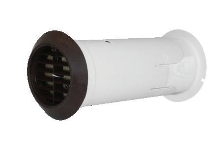
The Internal Fit Wall Kit has optional backdraught shutter models. Particularly useful with intermittent fans, the backdraught shutter will ensure no draughts and gusts come in to the home through the wall kit.

• Provides over 90% free area of duct
• Easier to install than a double air brick
• Guide vanes for improved duct connection
• Optional first fix duct section
Available in five colours, this low resistance air brick has been designed to comply with the latest Building Regulations Approved Document F, which requires a ventilation outlet to achieve a minimum of 90% of the cross sectional area of the ductwork.
Installing a single air brick is much simpler than a double air brick and offers more versatility for locations.
Suitable for installation with round 100mm and 125mm diameter and rectangular 204 x 60mm ducting.
Attaching duct to the air brick is simplified by the use of guide vanes which help locate the duct onto the spigot.
A 500mm section of 204 x 60 duct is available for first fix which ensures that connections are accessible after completion of building works.
Five colour options ensure that the low resistance air brick will be a match for almost any application.
Models
Model Stock Ref
White 449223
Brown 449224
Cotswold Stone 449225
Grey 449226
Terracotta 449227
1st Fix duct section 403255
500 x
x 60
Available Colours


Channel Fixing Clip (Pack of


Elbow Bend. 100mm to Rectangular. M to F
Elbow Bend. 125mm to Rectangular. M to F


**This part comes in Grey. Whilst we will look to maintain the colour of Grey, by the nature of adopting a recycled plastic the colour and shade may vary at any given time.

Elbow Bend. 150mm to Rectangular. M to F
Elbow Bend. 100mm to Rectangular. F to F
Flat Channel connector with Damper
Drop down section F to F
Single Air Brick Horizontal (System 60 Air Grille Adaptor is supplied with the Single Air Bricks)


Single Air Grille Soldier
**This part comes in Grey. Whilst we will look to maintain the colour of Grey, by the nature of adopting a recycled plastic the colour and shade may vary at any given time.
Flexible Ducting


Louvred Grille with Flyscreen Fitting
Round (M) 100mm to Rectangular (F/M) Adaptor


Round (F) 125mm to Rectangular (F) Adaptor
Round (F) 150mm to Rectangular (F) Adaptor


Short Round (M) 100mm to 110 x 54 (F) Adaptor

Round Ducting Insulated/Uninsulated


Round (F) 125mm to Rectangular (F) Adaptor
Circular Extract Diffuser
Manufactured from powder coated steel. Suitable for exhausting air and can be fitted directly to the duct or in the ceiling.
Round (F) 150mm to Rectangular (F) Adaptor


Circular Push-Fit Supply Diffuser
Manufactured from ABS. Easy to install by direct push-fit into duct. Suitable for supplying air and can be fitted directly to the duct or in the ceiling.
Short Round (M) 100mm to 110 x 54 (F) Adaptor
Circular Supply Diffuser
Manufactured from powder coated steel. Suitable for supplying air and can be fitted directly to the duct or in the ceiling.
Round Ducting Insulated/Uninsulated
Acoustic Mat
486mm x 486mm x 25mm thick foam mat for use as a resilient mounting for wholehouse units.

Circular Push-Fit Extract Diffuser
Manufactured from ABS. Easy to install by direct push-fit into duct. Suitable for supplying air and can be fitted directly to the duct or in the ceiling.
Free technical, installation and sales advice is available

Sales Centre:
Domestic & Commercial
Sales Tel: 0344 856 0590
Sales Fax: 01293 565169
Tech Support Tel: 0344 856 0594
Tech Support Fax: 01293 532814
Industrial
Sales Tel: 0344 856 0591
Sales Fax: 01293 534898
Tech Support Tel: 0344 856 0595
Tech Support Fax: 01293 532814
Web: www.vent-axia.com
Email: sales@vent-axia.com
All sales made by Vent-Axia Limited are made only upon the terms of the Company’s Conditions of Sale, a copy of which may be obtained on request. As part of the policy of continuous product improvement Vent-Axia reserves the right to alter specifications without notice.
Made in Britain
0923