HAVEN IAQ MODULES NOW AVAILABLE
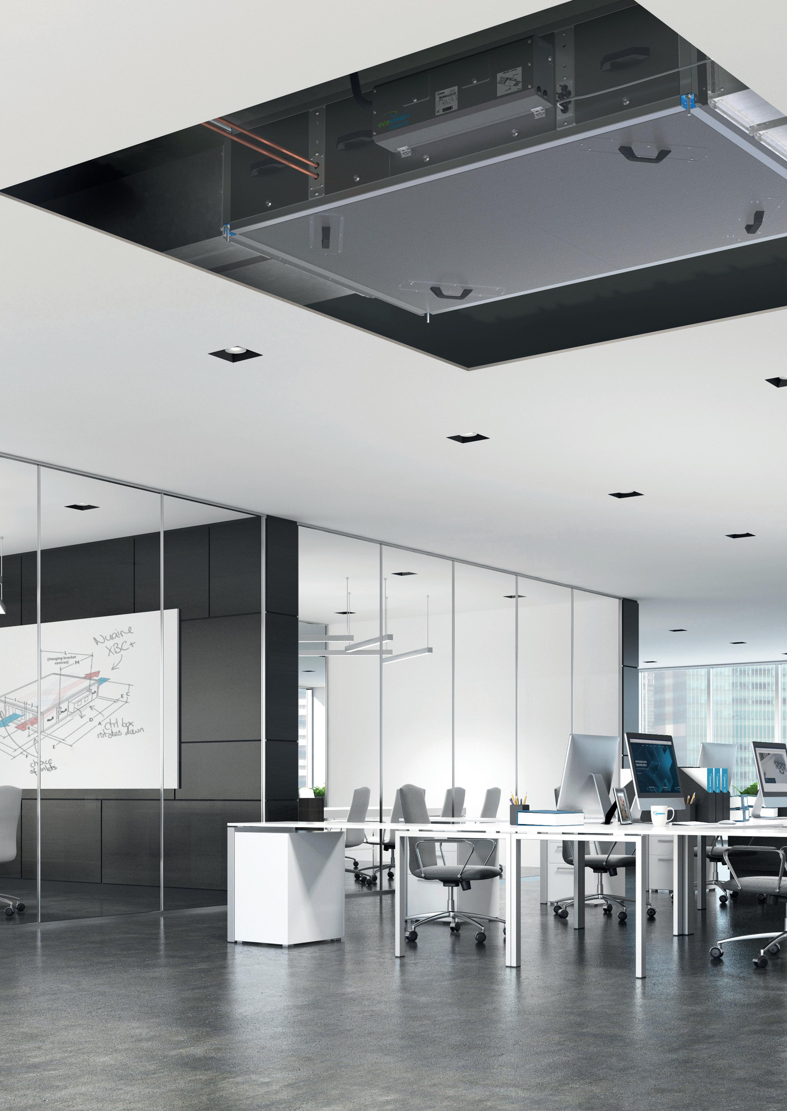
XBOXER XBC+ PACKAGED HEAT RECOVERY UNITS
CONTENTS
PROUD TO BUILD BRITISH
We’ve been pioneers in new air technology since 1966. Our heritage is in the design and manufacture of fans and ventilation systems. We put our energy into efficient ventilation so you don’t waste yours.
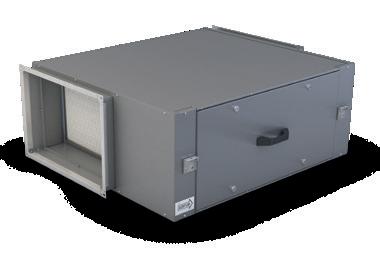
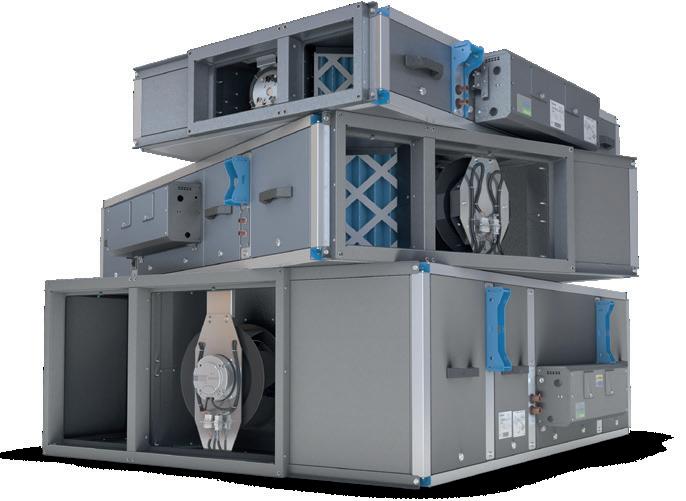
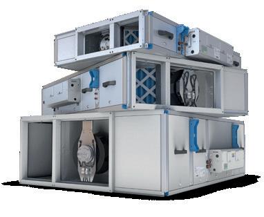
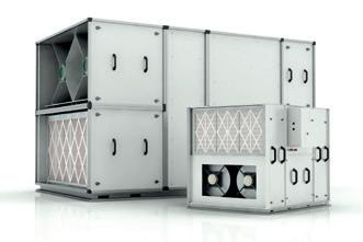
ABOUT PACKAGED HEAT RECOVERY UNITS
Heat recovery systems are the perfect solution for projects where airflow and occupant comfort needs to be guaranteed.
Pioneering
We lead the way in product innovation with a stream of ground-breaking products over decades.
Trusted
We have a reputation for our build quality. We establish long term relationships and are always transparent with our test data.
Heat recovery units are supply and extract systems designed to deliver fresh, filtered air into a building whilst also extracting stale air from the interior. Units contain a heat exchanger, which is capable of retaining heat that would otherwise be lost, and temper incoming air with this energy.
Agile
We’re one of the UK’s leading manufacturers, covering both residential and commercial air quality. We offer innovative advice and provide flexible solutions.

Expert Our team is made up of over 600 people, 50 of which have over 25 years’ experience. We have the skills and knowledge to help find the best solution for our customers.
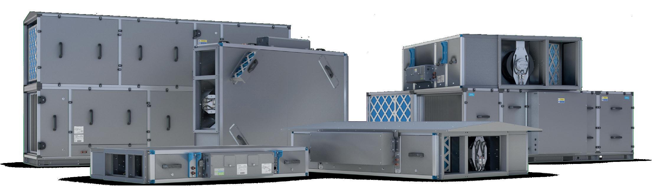
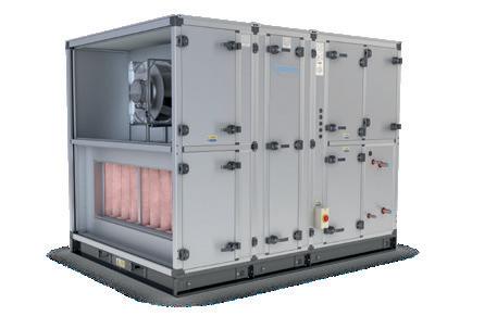
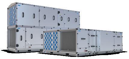
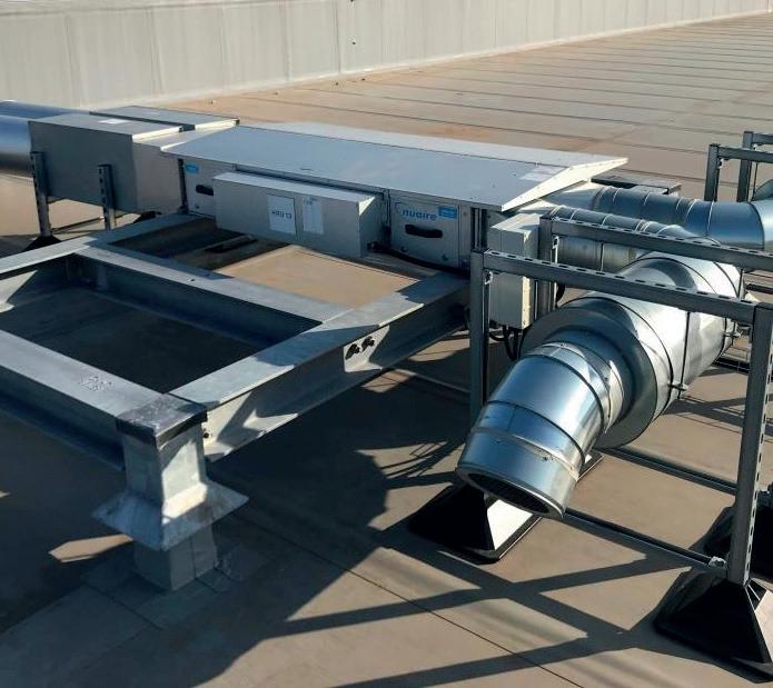
Our pedigree is in the design and manufacture of packaged heat recovery units that contain all the elements of a heat recovery system in a single system. We have been designing and perfecting packaged heat recovery technology for over 20 years - our track record means we can offer low-energy solutions for every commercial application, all manufactured in the UK to the highest standards.
Attentive
We’re expert listeners, rising to any challenge and going the extra mile for our customers. We add value by solving problems. We sell solutions, not fans.
Personal
We work closely with our customers and can provide bespoke solutions to meet their specific project needs. Many of our product ranges were developed this way.
For help with selecting a unit, speak to us on 02920 858200 or email: enquiries@nuaire.co.uk
Nuaire XBC+ units are manufactured in a factory production controlled environment using a PAS99:2012 Integrated Management System covering ISO9001:2015 Quality Management, ISO 14001:2015 Environmental Management and ISO 45001:2018 Occupational Health and Safety Management. Our product controls are regularly audited (both internally and by 3rd parties) to ensure our products and services are delivered in a repeatable manner to the highest quality. XBC+ units are CE marked and will fulfil the requirements of the UKCA Mark from 1st Jan 2021.
“Our expertise, experience and innovation are what makes us stand out from the rest of the market.”
Nuaire.
UK MADE XBOXER XBC+ 10-65 3 ABOUT PACKAGED HEAT RECOVERY UNITS 4 ABOUT XBOXER XBC+ 5 NEW CODING 6 XBC+ FEATURES 8 THE HISTORY OF NUAIRE HEAT RECOVERY 9 NUAIRE CASE STUDY EASTERN HIGH SCHOOL, CARDIFF 10 PRODUCT SELECTION 11 COMPLYING WITH BUILDING REGULATIONS 12 ECOSMART CONTROLS 14 ECOSMART CONTROLS SELECTION GUIDE 16 ECOSMART SENSORS & ENABLERS 18 XBC+ 10-65 COUNTERFLOW HORIZONTAL 20 XBC+ 10 22 XBC+ 15 24 XBC+ 25 26 XBC+ 45 28 XBC+ 55 30 XBC+ 65 32 XBC+ ENTHALPY 38 ANCILLARIES 44 HAVEN IAQ MODULE 50 DX COIL DATA 54 CONSULTANT SPECIFICATION XBOXER XBC+ PACKAGED HEAT RECOVERY UNITS PIONEERING NEW AIR TECHNOLOGY 2 3
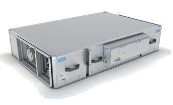
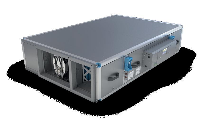
ABOUT XBOXER XBC+
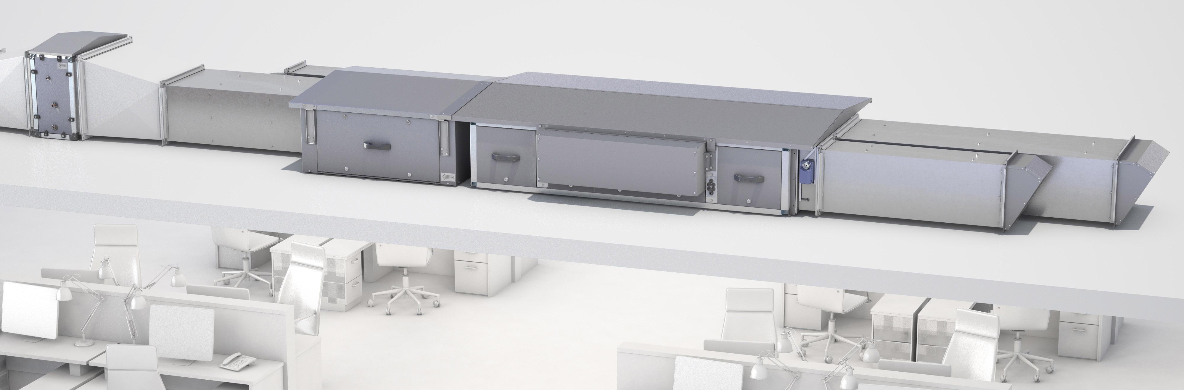
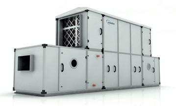
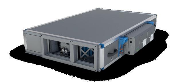
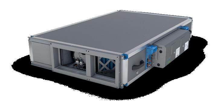
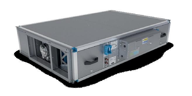
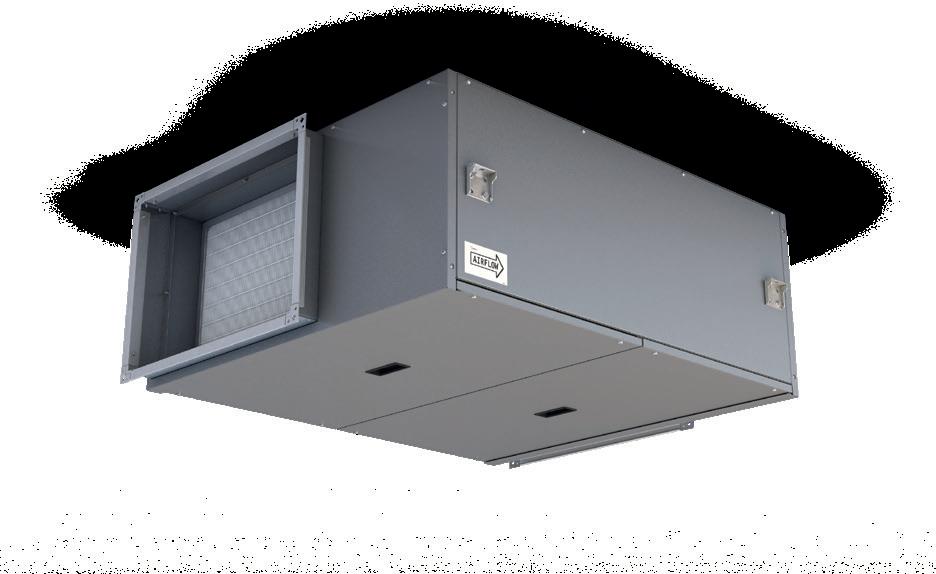
XBC is our market-leading range of packaged heat recovery units. Units are extremely low depth and are designed to save energy, improve indoor air quality and provide the lowest possible noise breakout.
XBC+ is our newest innovation in packaged heat recovery. We’ve taken the award-winning XBC and enhanced the unit further, making it easier still to install, commission, control and maintain. It was these features that earned XBC its leading position in the market, and now the best is better. The combination of innovative design and flexible control options provides our customers with the best possible heat recovery solution.
NEW CODING
The new XBC+ coding is longer than the classic XBC coding, giving you more options and choices. This ensures that each unit is selectable with key components unique to your specific project requirements. The new code is broken down into sections.
SECTION
The first section of the code dictates what unit is required, including sizing and heat-exchanger option. To denote the end of this section, we put a dash (-).
USE OUR NEW 3-STEP XBC+ CODE GENERATOR TO REDUCE TIME AND ERROR WHEN PLACING AN ORDER
Now you choose your heating options, including valve ports. Again, we denote the end of this section with another dash (-).
Finally, choose what ancillaries are required, such as constant pressure or a weather roof.
HIGHEST EFFICIENCY
Counterflow heat exchanger with efficiencies of up to 95%. Enthalpy heat exchanger option now available (sizes 25 and 45 only).
SPACE SAVING SOLUTION
Lowest depth by duty on the market.
FLEXIBLE HEATER OPTIONS
Electric and LPHW heater options available with choice of low and high kW output for both.
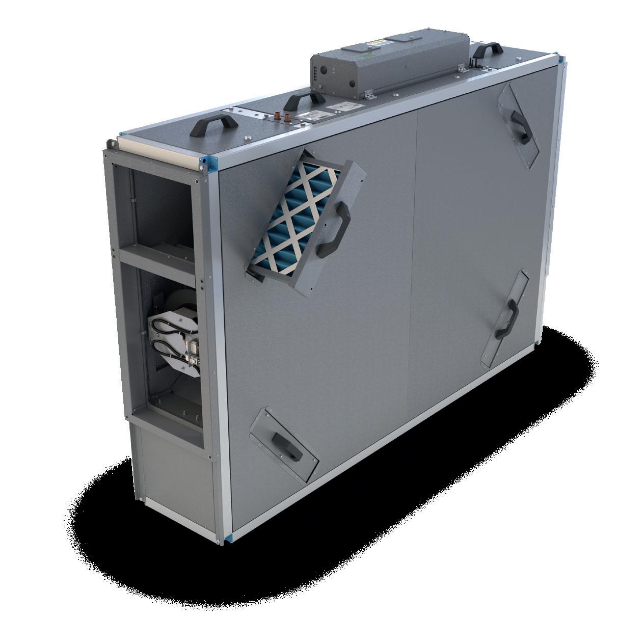
EASY MAINTENANCE Options for either bottom or side filter access as standard.
FULL CONTROL Integrated controls for quick and simple commissioning.
1. XBOXER range
2. C – Counterflow heat exchanger
E – Enthalpy block heat exchanger
3. Unit size
4. H – Horizontal layout
5. Filter grade (A = G4)
6. L – LPHW heater
E – Electric heater
N – No heater
7. H – High duty heater
L – Low duty heater
N – No heater
8. 4 – 4 port valve (in-built)
2 – 2 port valve (supplied loose)*
N – No valve (bare coil)
*2 port valve (supplied loose) is available as ancillary, refer to Nuaire Selector.
At this point you should have a completed code. Codes will always be 18 characters long, including any and all dashes. If something is not required, that section of the code will always be replaced by something else e.g. Electric heater = E, no heater = N.
9. E – Ecosmart Classic controls
C – Connect controls
T – Trend controls
N – No control
10. P – Constant pressure - – No constant pressure
11. L – Left controls handing
R – Right controls handing
12. B – Bottom filter access
S – Side filter access
13. 1 – Standard unit finish (Magnelis®*)
4 – Coastal unit finish (C4)
14. S – Internal unit
W – External unit with weather roof (factory fitted)
This means that if something is missing from the code, our estimating team will quickly be able to spot it and double check with you; rather than potentially missing something from the unit or supplying something that isn’t needed.
*This range is offered with Magnelis® panelling as standard which provides an industrial finish, enabling enhanced corrosion resistance. Paint finishes are available for aesthetically critical applications.
CODING XBC45HA-LH2-EPLS1S
1: UNIT AND CASE
SECTION 2: HEATING OPTIONS
SECTION 3: ANCILLARIES
XB C 45 H A –1 2 3 4 5 L H 4 –6 7 8 E P L S 1 S 9 10 11 12 13 14
XBC+ IMPROVES ON THE ORIGINAL WITH...
XBOXER XBC+ PACKAGED HEAT RECOVERY UNITS
4 5
PIONEERING NEW AIR TECHNOLOGY
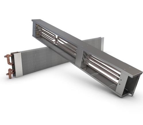
COIL FEATURES
HEATING COIL OPTIONS
Fitted LPHW or electric heater battery options available.
DX AND CHILLED WATER
Bolt-on cooling coil modules available as a matched ancillary.
CONTROL FEATURES
BUILT IN ECOSMART CONTROLS
Ecosmart Classic, Connect, or Adapt controls available with XBC+ units. Allowing simple integration into supervisory control networks using BACnet.
QUICK COMMISSIONING
Integrated supply and extract fan allows precise system duty which can be quickly and accurately set (Ecosmart models only).
100% SUMMER BYPASS
Bypass operates automatically via integrated temperature sensors and pre-defined control programme.
NO CONTROL AVAILABLE
Allowing for a control system to be designed, specified, fitted, and tested by others.
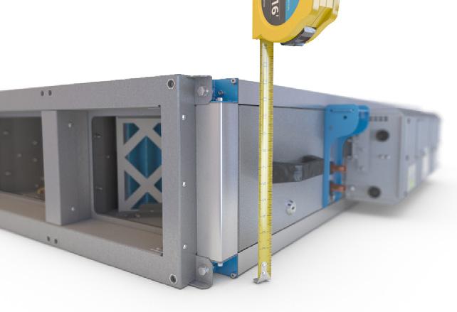
INSTALL FEATURES
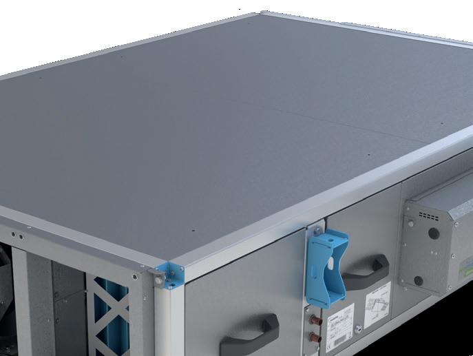
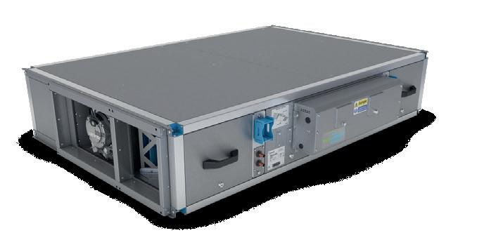
SPACE SAVING SOLUTION
Lowest depth by duty on the market and only 260mm side access required for filter removal.
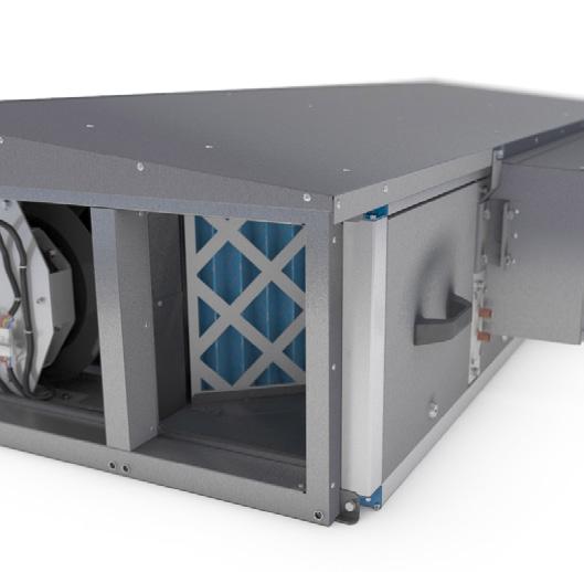
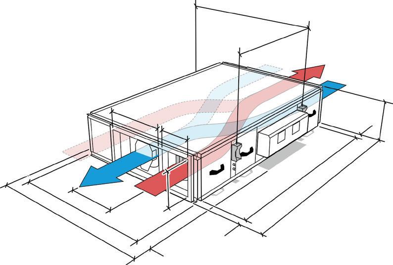
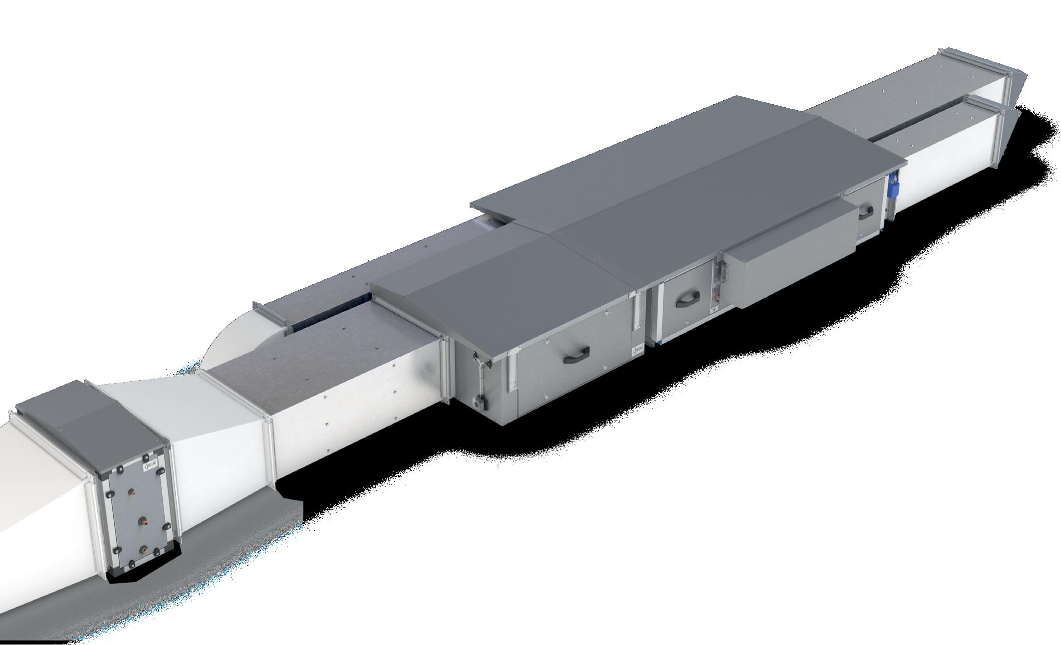
FLEXIBLE LAYOUT DESIGN
Supply/discharge connections are on unit centreline. Intake/extract connections are configurable on site to either side of the unit.
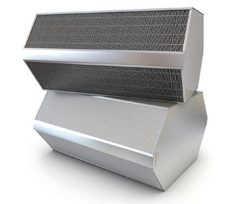
ANCILLARY FEATURES
MATCHED ANCILLARIES
Wide range of ancillaries available, including matched silencers, advanced filtration, and bend silencers.
HAVEN IAQ MODULE
In line IAQ module available with filtration from G4 (Coarse 75%) to F7 (ePM1 55%) all the way up to activated carbon.
WEATHER ROOF
Available factory-fitted or later as an ancillary.
CONSTRUCTION FEATURES
ROBUST CONSTRUCTION
Manufactured from corrosion resistant and extremely durable Magnelis®*.
LOW NOISE LEVELS
Units have an asymmetric, high mass, double-skinned wall construction (patented) with integral acoustic barrier mat ensuring low breakout noise levels.
HIGH CLASSIFICATION
Units are tested to meet Class L2 leakage requirements.
HIGH PERFORMANCE
Utilising latest EC motor technology for low specific fan power (SFP).
5 YEAR WARRANTY
Ecosmart models come with 5 year warranty for peace of mind.
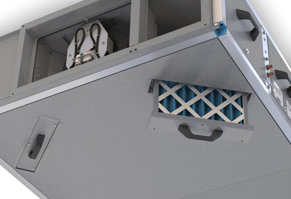
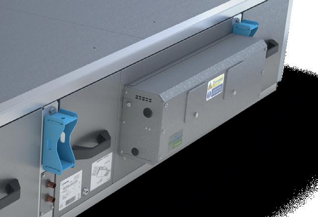
INSTALL FEATURES
INTEGRAL MOUNTING BRACKETS
Units come with pre-fitted mounting brackets for simple drop-rod installation.
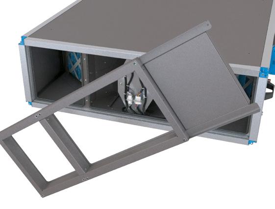
SIDE OR BOTTOM ACCESS
Units are available in either side or bottom access for more design flexibility.
 *This range is offered with Magnelis® panelling as standard which provides an industrial finish, enabling enhanced corrosion resistance. Paint finishes are available for aesthetically critical applications.
XBOXER XBC+ PACKAGED HEAT RECOVERY UNITS
*This range is offered with Magnelis® panelling as standard which provides an industrial finish, enabling enhanced corrosion resistance. Paint finishes are available for aesthetically critical applications.
XBOXER XBC+ PACKAGED HEAT RECOVERY UNITS
6 7
PIONEERING NEW AIR TECHNOLOGY
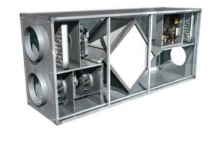
THE HISTORY OF NUAIRE HEAT RECOVERY
Our track record in packaged heat recovery units means we can offer low-energy solutions for every commercial application. All manufactured in the UK to the Nuaire standard.
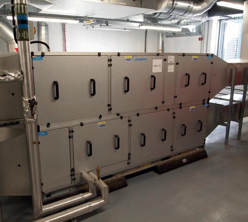
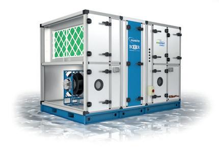
Our pedigree in commercial heat recovery spans decades - all the way back to 1998 with the launch of our Ecosmart Boxer range. Unlike many units at the time, Ecosmart Boxer combined all the features of a heat recovery system, including supply, extract and heat exchanger sections, into an easy to specify and install packaged solution, rather than supplying them separate to combine on site.
Since then, we’ve taken our design philosophy to lead the way in commercial heat recovery.
NUAIRE CASE STUDY EASTERN HIGH SCHOOL, CARDIFF
The new facility, which accommodates 1100 pupils and 100 staff members, consists of 59 classrooms, open teaching spaces, dining areas, a gym and an activity studio. Over £26 million has been invested into the project, which is designed to be a modernised and more stimulating space in which to teach and learn.
DID YOU KNOW?
WE CONTINUE TO DEVELOP OUR OFFERINGS TO MEET MARKET AND CUSTOMER DEMANDS, BUT EVEN OUR OLDER RANGES ARE STILL GOING STRONG.
DESPITE THE FACT IT WAS LAUNCHED OVER 20 YEARS AGO, THE ECOSMART BOXER RANGE IS STILL A HIGHLY SPECIFIED UNIT. NEWLY GRADUATED AND VETERAN CONSULTANTS ALIKE PRAISE ITS ENERGY-EFFICIENCY AND HIGH PERFORMANCE, ALL IN A SINGLE PACKAGE.
The challenge
A major objective throughout all stages of the project was ensuring a high level of energy efficiency; the school intends on having the lowest possible carbon footprint as possible.
Rhys Tatchell, Area Sales Manager for Nuaire worked closely with McCann & Partners on the project. He explained:
“Eastern High School has been designed to create a high level of wellbeing and indoor air quality, which will improve the student’s ability to concentrate, as well as the standard at which teachers can perform. The XBC range of units has one of the best heat exchangers in the industry, with efficiencies of up to 96% - This will aid the school massively in minimizing its carbon footprint and achieving a committed standard of energy efficiency.”
To meet strict SFP energy requirements, a non-standard, larger sized XBC unit was specified for the project. McCann & Partners was able to make use of Nuaire’s BIM Level 2 library and collection of Revit families to accurately alter designs and devise a solution to the site’s space restrictions. From this, McCann & Partners
coordinated with other building services to ensure the heat recovery system would be the right size and layout for the space available on site.
The solution
Nuaire’s XBC systems, paired with the natural ventilation, have resulted in a demand ventilation system where with the highest levels of heat are recovered, saving as much energy as possible.
The school has achieved an Energy Performance Certificate Grade ‘A’ and BREEAM 2014 rating of ‘Excellent’ for its ability to achieve an ambitious level of energy-efficiency. Tony Williamson has stated: “The air quality in the new campus is far superior to what they had in the old school.”
While at Eastern High School, Nuaire had the opportunity to use the fantastic facility as the location for our Health Check Video. The Nuaire Health Check service ensures your AHU or Packaged Heat Recovery Unit is set up to the Nuaire standard, prior to airflow commissioning. For more info, please visit: Health-Check
THE SCHOOL UTILISES A ‘TRAFFIC LIGHT’ TYPE NATURAL VENTILATION SYSTEM WITH ENHANCED SINGLE SIDED VENTILATION IN CLASSROOMS. WHERE NATURAL VENTILATION COULD NOT BE PROVIDED, MECHANICAL VENTILATION WITH HEAT RECOVERY WAS SPECIFIED USING NUAIRE XBC UNITS.
GRAHAM CARR OF MCCANN & PARTNERS

1998 2015 2016 2008 2012 2020 2010 2011 Ecosmart Boxer XBOXER XBC Sizes 75 and 85 Boxer BPS Squrbo Xbox Boxer Bespoke Thermal Wheel AHU Boxer Neptune XBOXER XBC+ Boxer Bespoke AHU XBOXER XBC
XBOXER XBC+ PACKAGED HEAT RECOVERY UNITS
8 9
PIONEERING NEW AIR TECHNOLOGY
PRODUCT SELECTION
Nuaire’s customers are involved in the development of every type of educational environment with varying complexity including the development of new build and refurbishment projects in live environments.
COMPLYING WITH BUILDING REGULATIONS

The following information is relevant to the selection of fans for Ventilation Systems, indicating the maximum specific fan powers allowed under Part L (Refer to the Non-domestic Building Services Compliance Guide: 2021 Edition for further details). The SFP for the entire system (including both supply & extract fans) shall be less than that allowed by these figures. The following tables are the maximum values allowed under Building Regulations when finally commissioned.
Nuaire assists its customers to deliver their projects and to keep within their project programme, quality and cost. Over the years Nuaire’s knowledge and understanding of current government education legislation has grown significantly.
The Priority School Building Programme (PSBP) Facilities Output Specification launched by the Education Funding Agency (EFA) has proposed some significant, positive and welcome changes to school ventilation specifications.
We understand the many challenges and regulations that modern building ventilation must meet... and our technical team are on hand to assist with product selections.
NUAIRE’S CUSTOMERS CREATE INSPIRATIONAL LEARNING ENVIRONMENTS AND HELP FACILITATE MAJOR CHANGES IN EDUCATIONAL SPACES.
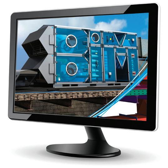
Building Information Modelling (BIM) is both a new technology and a new way of working. BIM is a term that has been around for a while in manufacturing and engineering industries, and is now beginning to make an impact in the construction sector.
Nuaire has a dedicated BIM Team offering libraries of Revit® compatible BIM models to meet customers’ exact specification. Nuaire’s libraries offer collision detection through geometry, connection positions and weights. Project specific performance criteria and support for design, project management and building operations can be requested which will result in improved design efficiency.
To find out more visit: www.gov.uk/government/collections/priority-school-building-programme-psbp.
To download Nuaire’s Revit® compatible BIM models simply scan the QR code or visit www.nuaire.co.uk/BIM and click on the library. Alternatively, simply email the team BIM@nuaire.co.uk with your request.
*Note: The weighted average is calculated by the following formula: Pmains,1 SFP +Pmains,2 SFP2 +Pmains,3 SFP3 +... Pmains,1+Pmains,2+Pmains,3+... where Pmains is useful power supplied from the mains in W
dehumidifier (air conditioning system)
Example: For a central mechanical ventilation system with heating and cooling, and heat recovery via a plate heat exchanger plus return filter: SFP = 1.6 + 0.3 + 0.1 W/(l/s) = 2.0 W/(l/s)
minimum dry heat recovery efficiency for heat exchangers in new and existing buildings
Section 6 (2015 Edition)
System type Specific fan power (W/(l/s) New Buildings Existing Buildings Central balanced mechanical ventilation system with heating and cooling 1.6 2.2 Central balanced mechanical ventilation system with heating only 1.5 1.8 All other central balanced mechanical ventilation systems 1.1 1.6 Zonal supply system where the fan is remote from the zone, such as ceiling void or roof mounted units 1.1 1.4 Zonal extract system where fan is remote from zone 0.5 0.5 Zonal supply and extract ventilation units, such as ceiling void or roof units serving single room or zone with heating and heat recovery 1.9 1.9 Local balanced supply and extract ventilation system such as wall / roof units serving single area with heat recovery 1.6 1.6 Local supply or extract ventilation units such as window wall / roof units serving a single area (eg. toilet extract) 0.3 0.4 Other local ventilation supply or extract units 0.5 0.5 Fan assisted terminal (VAV) unit 1.1 1.1 Fan coil units (rating weighted average*) 0.5 0.5 Kitchen extract, fan remote from zone with grease filter 1.0 1.0 The weighted average is calculated by the following formula: Pmains,1 SFP +Pmains,2 SFP +Pmains,3 SFP3 +... Pmains,1+Pmains,2+Pmains,3+...
Extending SFP for
Component (SFP (W/ (l/s)) Additional return filter for heat recovery +0.1 HEPA filter +1.0 Heat recovery - thermal wheel system +0.3 Heat recovery - other systems +0.3 Humidifier dehumidifier (air conditioning system) +0.1 Recommended
exchangers
Heat exchanger
Dry Heat recovery efficiency Plate heat exchanger 50% Heat pipes 60% Thermal wheel 65% Run around coil 45% System type Specific fan power (W/(l/s) New Buildings Existing Buildings Central balanced mechanical ventilation system with heating and cooling 2.0 2.6 Central balanced mechanical ventilation system with heating only 1.9 2.2 All other central balanced mechanical ventilation systems 1.5 2.0 Zonal supply system where the fan is remote from the zone, such as ceiling void or roof-mounted units 1.1 1.4 Zonal extract system where fan is remote from zone 0.5 0.5 Zonal balanced supply and extract ventilation units, such as ceiling void or root units 2.3 2.3 Local balanced supply and extract ventilation system such as wall / roof units 2.0 2.0 Local supply or extract ventilation units, such as window / wall / roof units (e.g. toilet extract) 0.3 0.4 Other local ventilation supply or extract units 0.5 0.5 Fan assisted terminal variable air volume (VAV) unit 0.5 0.5 Fan coil unit (rating weighted average*) 0.4 0.4 Kitchen extract, fan remote from zone with grease filter 1.0 1.0
Permissible maximum specific fan power and pressure drop in air distribution systems. Maximum specific fan powers in air distribution systems new and existing buildings.
where Pmains is useful power supplied from the mains in W
additional components in new and existing buildings
minimum dry heat recovery efficiency for heat
in new and existing buildings
type
Extending SFP
and
Component (SFP (W/ (l/s)) Additional return filter for heat recovery +0.1 HEPA filter +1.0 Heat recovery - thermal wheel system +0.3 Heat recovery - other systems +0.3 Humidifier
+0.1
Recommended
Heat exchanger type Dry Heat recovery efficiency Plate heat exchanger 50% Heat pipes 60% Thermal wheel 65% Run around coil 45%
for additional components in new
existing buildings
/
XBOXER XBC+ PACKAGED HEAT RECOVERY UNITS
10 11
PIONEERING NEW AIR TECHNOLOGY
ECOSMART CONTROL PLATFORM
IT’S SO SMART IT’S SIMPLE
Nuaire and ventilation controls have history.
Back in the early 1970s it was standard practice to specify fans as close to the design duty as possible, but without any speed controllers. Understanding the inefficiency this can cause, Nuaire, headed by our then owner and CIBSE Chairman, Brian Moss, developed the first twin fan controller – a cost-effective way to save energy and reduce running costs. Since then, the Nuaire brand has become synonymous with energy-saving controls.
Designed to meet all project requirements, Ecosmart Adapt (with Trend) is the standard for control.
Trend IQ422/12/LAN/BAC/230 inside with full BMS integration via BACNET.
Ecosmart Adapt with Trend provides control of the ventilation including the heating, or cooling allowing unitary control and full BMS integration via BACnet IP. The Ecosmart Adapt with Trend control system includes an IQ422/12/LAN/ BAC/230 controller which is pre-configured and the unit and control assembly is functionally tested at Nuaire before customer delivery.
“The management and control of modern buildings grow ever more sophisticated. A Building Energy Management system (BEMS) must be tailored to suit each customer’s specific control requirements. It must provide efficient HVAC control, coupled with the flexibility to accommodate changes in occupancy status and staff relocation at short notice; whilst simultaneously delivering improved comfort conditions. A BEMS must also provide real time management information and control, enabling customers to achieve significant energy savings” (TREND).
Energy-efficient demand based control providing network connectivity and advanced functionality.
Ecosmart Connect provides control of the ventilation including the heating, or cooling allowing unitary control and full BMS integration via BACnet (MS/TP) (Upgrade to IP network available).
The Ecosmart Connect controller is pre-configured and the unit and control assembly is functionally tested at Nuaire before customer delivery.
Reduced installation and on-site commissioning time on new and retrofit projects.
Advanced tools within the control automate many tasks, simple to use displays minimise data input, whilst reducing commission time and potential human error.
Reduced installation and on-site commissioning time on new and retrofit projects.
Advanced tools within the control automate many tasks, simple to use displays minimise data input, whilst reducing commission time and potential human error.
• Ease of use - Using Ecosmart Adapt with Trend will deliver substantial savings on utility costs.
• Peace of mind - Ecosmart Adapt with Trend has a 5 year warranty.
An Ecosmart system combines systems into a simple package, saving space but also time spent installing and commissioning. Alternatively, we offer ‘No Control’ – a simple terminal box for supply and extract fan motor wiring for interfacing to custom-built control panels (by others).
SYSTEM
Our range of control options means there is a solution for all requirements, no matter how simple or complicated.
The UK’s leading energy-efficient plug-and-play solution. Demand ventilation at your fingertips.
Varying the ventilation rate in a building to suit changing occupant levels used to be an expensive option – Ecosmart brings this within everyone’s pocket. Minimising energy losses through re-heating (or cooling) the air replaced through ventilation is at the top of the agenda; building regulations make this a necessity. Ecosmart not only saves energy and carbon emissions it prolongs the life of the heat recovery unit. Choosing Ecosmart is your reliable option, used by design engineers for many years and is now an integral feature of most Nuaire fans.
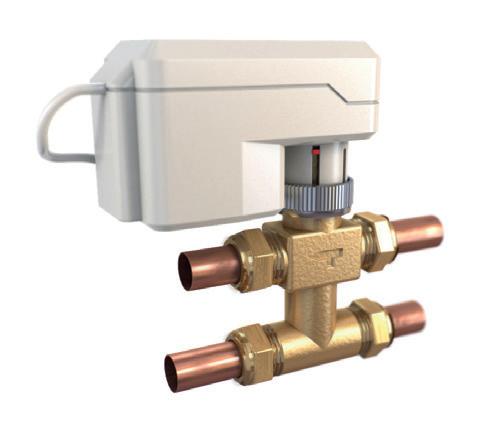
• Saves time on site - Ecosmart controls are all pre-assembled, configured and installed directly into the heat recovery units, this includes valves and actuators, pipework etc. which helps significantly reduce the time spent on site.
• Simpler system - No need for VCD (directly on the fan) no wasted energy or noise generation because air volume can be precisely set via integrated speed control.
• Ease of use - Using Ecosmart Connect will deliver substantial savings on utility costs.
• Peace of mind - Ecosmart Connect has a 5 year warranty.
available on relevant unit.
• Simple & precise commissioning - As recommended in Part L, Ecosmart enables the system to be accurately commissioned via integrated speed control. If the unit is controlled by 0-10V BMS the system’s response to a 0-10V dc BMS signal is given in the table above.
No control is fan speed only and are suitable for 2-10V adjustment (by others). The heat recovery unit will have a side mounted terminal box for connection to the fans (230V, 50Hz LNE and 2-10V*) and bypass actuator (where applicable). No control is for BMS by others. No control has a 2 year warranty.
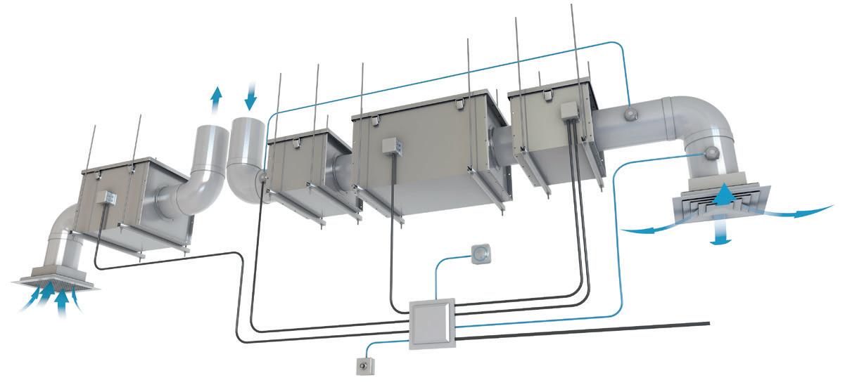
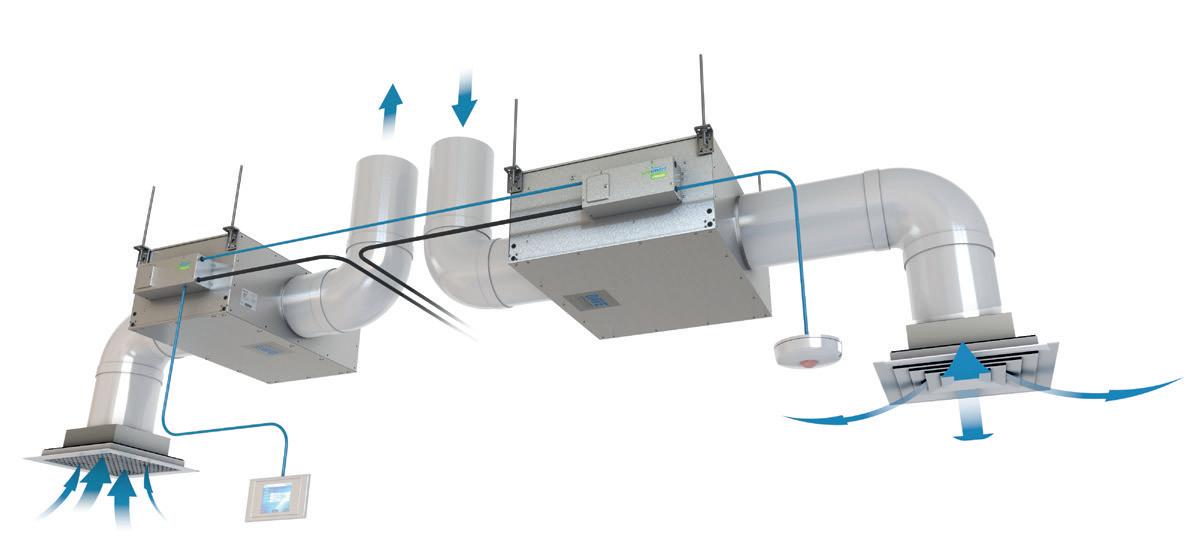
Demand Ventilation Solutions
is a conventional ventilation system compared to one using Ecosmart controls.
Below
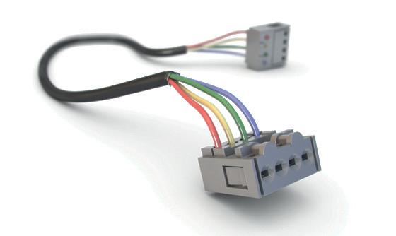
1. Integrated control 2. Optional CO2 sensor 3. User control 4. (SELV) 12V cable 5. Optional PIR sensor 6. 230V Electricity supply 1. PVC ducting 2. Filter 3. Air pressure switch 4. Temperature switch 5. Control panel 6. User control 7. 230V Electricity supply 8. Electrical cabling 230V 9. Electrical heater 10. Time clock CONVENTIONAL SUPPLY & EXTRACT VENTILATION SYSTEM ECOSMART SUPPLY & EXTRACT VENTILATION SYSTEM 1 1 2 8 5 10 7 6 9 3 4 EXTRACT UNIT SUPPLY UNIT EXTRACT UNIT SUPPLY UNIT 1 1 2 5 6 3 4 SIMPLE PLUG-AND-PLAY
Ventilation mode Cooling mode* Heating mode* Local control 0.00 -OFF / trickle 0.25 -Speed 1 0.50 0.75 1.00 Speed 2 1.50 1.75 2.00 Speed 3 2.50 2.75 3.00 Speed 4 3.50 3.75 4.00 Speed 5 4.50 4.75 5.00 Speed 6 5.50 5.75 6.00 Speed 7 6.50 6.75 7.00 Speed 8 7.50 7.75 8.00 Speed 9 8.50 8.75 9.00 Speed 10 9.50 9.75 10.00 *Only
No Control
XBOXER
12 13
XBC+ PACKAGED HEAT RECOVERY UNITS PIONEERING NEW AIR TECHNOLOGY
ECOSMART CONTROLS SELECTION GUIDE
*Each sensor module can have multiple sensors.(up to 3 per module). For further details of Ecosmart Controls Platform, refer to website: www.nuaire.co.uk
XBOXER XBC+ PACKAGED HEAT RECOVERY UNITS PIONEERING NEW AIR TECHNOLOGY 14 15
CONTROLLER SOFTWARE NO CONTROL (BC) (ES) (CO) BACnet (MS/TP) (AT) Based on TREND IQ422 BACnet (IP) Controller Software N/A Advanced Software Basic Softwre (can be re-written by others) Heat Exchange Bypass Control Strategy Basic Optimised Basic Supply Temperature Control Strategy Yes Yes Yes Room Temperature Control Strategy No Yes No Switched Live Enable Input Yes Yes Yes Switched Live Fan Boost No No Yes Switched Live Configurable Input (Heat or Fan Boost) No Yes No Volt Free Enable Input No Yes Yes Volt Free Fan Boost No No Yes Volt Free Configurable Input (Heat or Fan Boost) No Yes No Trickle Mode Yes Yes Yes Fan Run-On Yes Yes Yes Fan Run-On (Intelligent) No Yes No Run/Fault/Heat/Cool Volt Free Outputs Yes Yes Yes I/O Damper Control Yes Yes (via run relay) Yes (via run relay) Heat Dissipation Run-on Yes Yes Yes Frost Protection Routine Yes Yes Yes Low Supply Temp Fan Cut-out No Yes Yes Scheduling Yes (via ES-LCD/LCD2) Yes Yes CO2 Based Fan PID Loop ES CO2 Yes Yes Humidity Based Fan PID Loop ES-HUM Yes No Pressure Based Fan PID Loop CP version available Yes No Night Cooling Mode No Yes Yes Purge Mode No Yes Yes Hibernate Mode (open all valves) No Yes No Fan Speed Adjustment Yes Yes Yes Fan Speed Control Only Yes No No No 0 - 10V Fan Speed Input Yes Yes Yes 0 - 10V Temperature Sensor Input No Yes No 0 - 10V Humidity Sensor Input No Yes No 0 - 10V Pressure Sensor Input No Yes No 0 - 10V CO2 Sensor Input No Yes No CONTROLLER HARDWARE NO CONTROL (BC) (ES) (CO) BACnet (MS/TP) (AT) Based on TREND IQ422 BACnet (IP) Fail Safe Thermal Trip Yes Yes Yes Condensate Pump Monitoring Yes Yes Yes Din Rail Mounted Control No Yes Yes Quick Connect Terminals No Yes Yes 24VAC Auxiliary No Yes Yes HMI Commissioning Display Yes only via commissioning PCB Yes By others BACnet LCD/LCD2 Touch Screen Display No Yes By others ROOM MODULES Plug & Play Sensors Yes Yes No Max Number of Sensors 31 devices on any system 4 sensor modules* By others Quick Connect Plugs Yes Yes By others Twisted Pair Cable Compatible No Yes By others Commissioning Port No Yes By others Temperature Yes Yes By others CO2 Yes Yes By others Humidity Yes Yes By others 3-Speed Override No Yes By others PIR Yes Yes By others Setpoint Adjust Yes (on sensor) Yes By others Multiple Setpoints Supported No Yes By others Room Temperature Display No Yes By others Room Humidity Display No Yes By others Fan Speed Display No Yes By others Occupancy Status Display No Yes By others Network Error Display Yes Yes By others NETWORKING BEMS Compatible No Yes Yes BMS Compatible 0-10V Input BACnet via MS/TP (BACnet via IP optional) (BACnet via IP) MONITORING Web Connectivity N/A Yes Yes Energy Monitoring N/A Yes Participation via TREND network Energy Metering N/A Yes Participation via TREND network
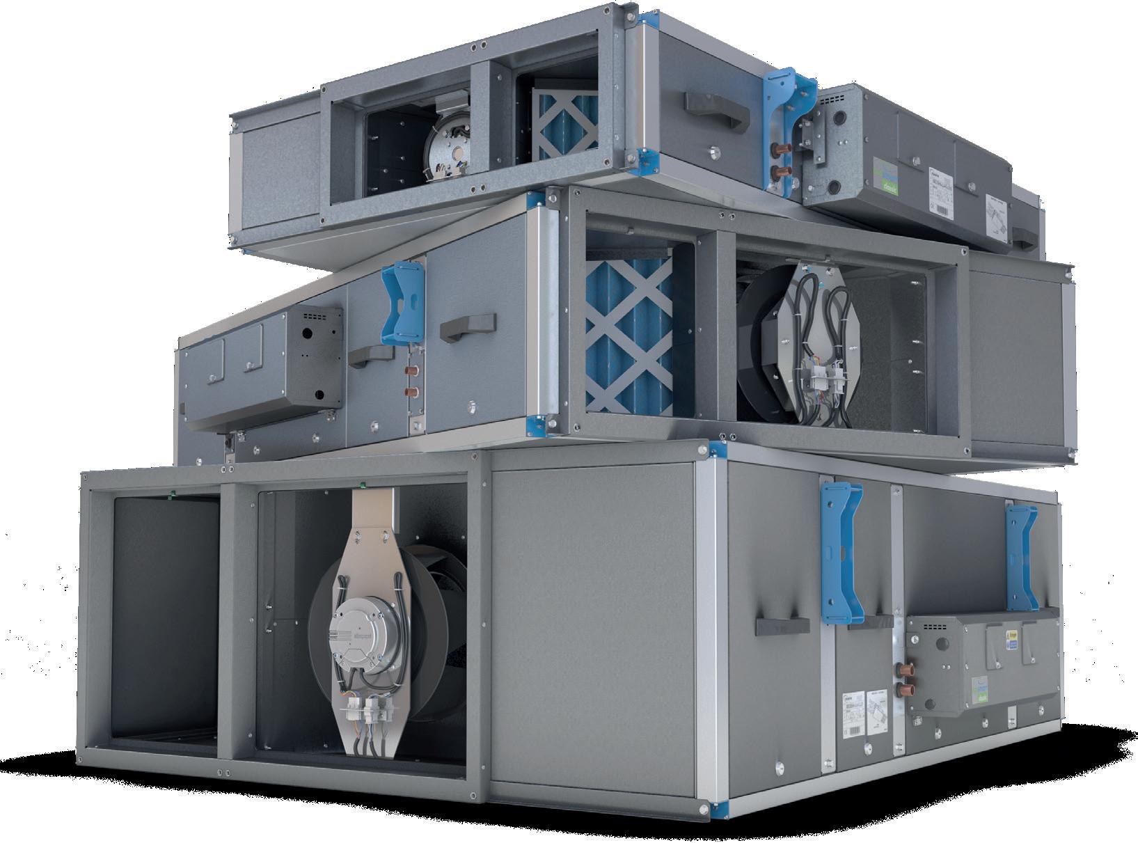
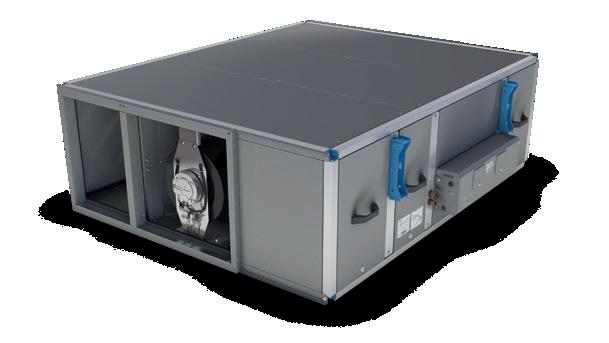
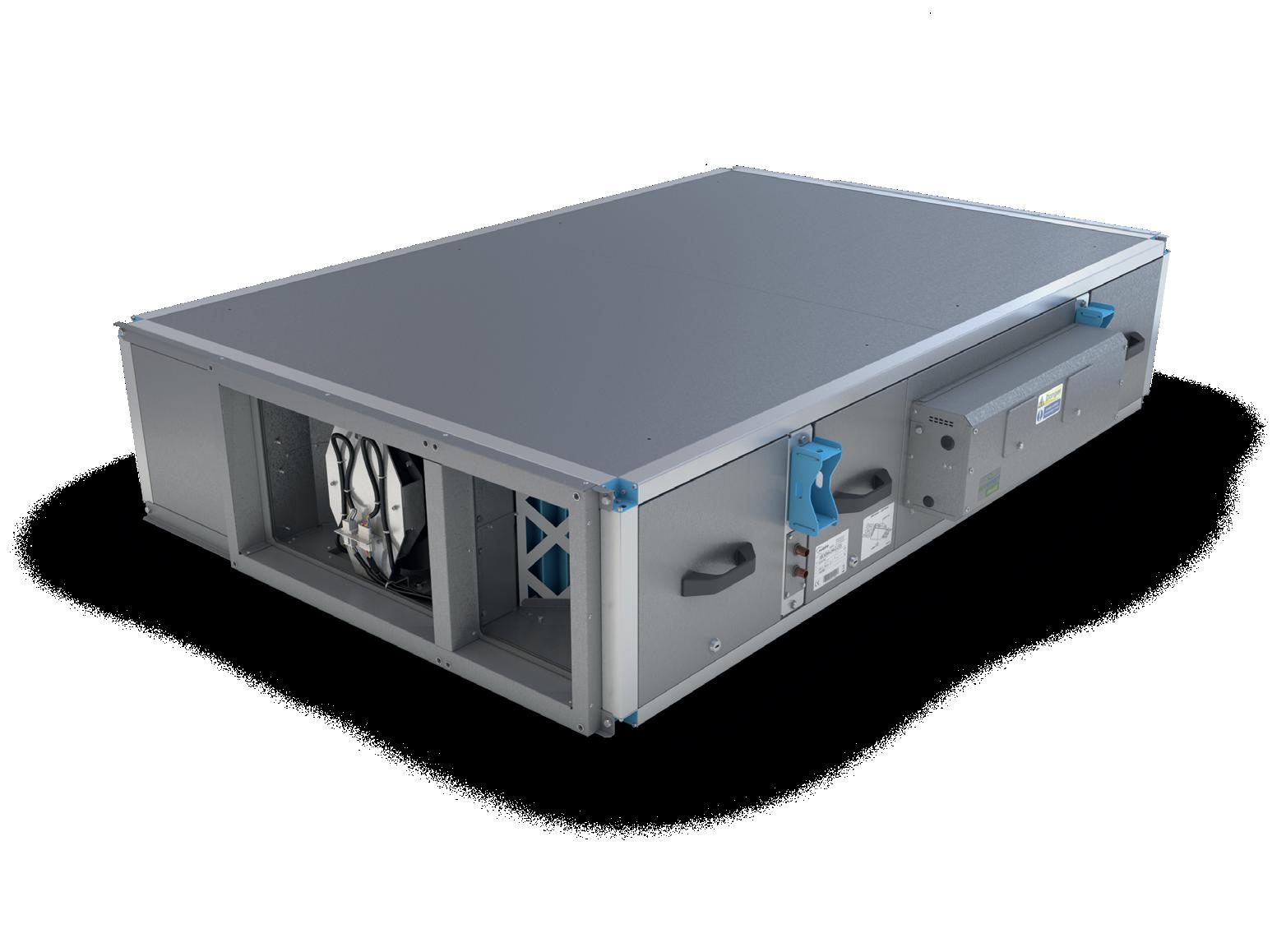
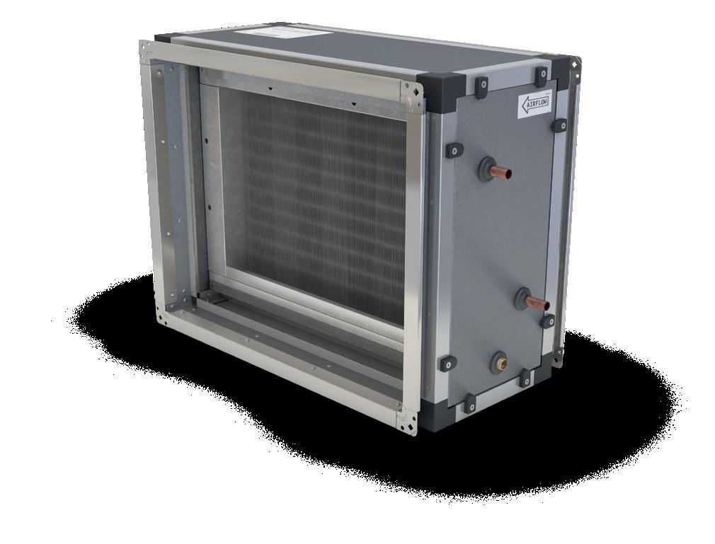
XBOXER XBC+ 10-65 COUNTERFLOW HORIZONTAL
XBC+ is the successor to the UK’s number one energy-efficient range of packaged heat recovery unit.
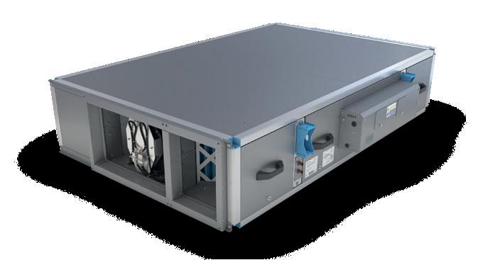
Smaller, quieter and easier to install than the current market offering, our award-winning range has earned its leading position by saving energy and time on site. The combination of innovative design and state-of-the-art controls ensure the best possible indoor air quality, whilst helping them reduce energy and save money.
XBOXER XBC+ 10-65 COUNTERFLOW HORIZONTAL
HIGH EFFICIENCY
Counterflow heat exchanger efficiency of up to 95%.
ADJUSTABLE DUCT OPTIONS
Inlet positions can be changed at installation stage for complete install flexibility.
EASY MAINTENANCE Choice of either bottom or side filter access as standard.
FULL CONTROL
Integrated controls for quick and easy commissioning.
XBOXER XBC+ PACKAGED HEAT RECOVERY UNITS PIONEERING NEW AIR TECHNOLOGY 18 19
Page Duty Range (Free Air) Case Size (L x W x H mm) Size 10 20 Up to 100 l/s 1600 x 1000 x 260 Size 15 22 Up to 200 l/s 1600 x 1000 x 260 Size 25 24 Up to 400 l/s 1713 x 1160 x 346 Size 45 26 Up to 500 l/s 1913 x 1262 x 405 Size 55 28 Up to 600 l/s 1900 x 1560 x 470 Size 65 30 Up to 800 l/s 1913 x 1570 x 624
XBOXER XBC+ PACKAGED HEAT RECOVERY UNITS
XBOXER XBC+ 10
PERFORMANCE & TECHNICAL INFORMATION
PIONEERING NEW AIR TECHNOLOGY
Based on air on temperature of 10°C.
FAN CONFIGURATION
*G4 (EN779:2012) / ISO Coarse 75% (ISO 16890).
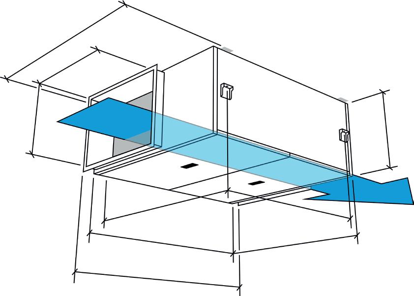
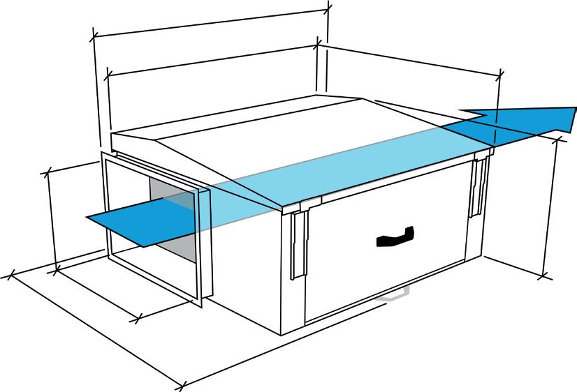
DIMENSIONS (mm)
2 attenuator flanges are attached to every unit. Add 50mm to length dimension to include both flanges. Weather roof is separate code and can be retro fitted on site. Units must be installed with a minimum clearance of 260mm from a wall or barrier. This will provide access to filters, coil, fan, heat exchanger, condensate tray and pump.
20 21
PERFORMANCE CHART 350 300 250 200 150 100 50 0 Unit Airflow (m³/s) 0 0.02 0.04 0.06 0.08 0.1 0.12 TECHNICAL INFORMATION HEATER TYPE VOLTAGE PHASE FREQUENCY INPUT POWER (W) FAN SPEED rpm) FLC (A) SC (A) MAX OPERATING TEMPERATURE (°C) UNIT WEIGHT kg LPHW 230 1 50 160 3200 1.5 1.5 40 147 Electric* 230 1 50 160 3200 9 9 40 155 None 230 1 50 160 3200 1.5 1.5 40 143 Relevant to BC, ES, CO or AT control types. *Inlcudes 1.5kW electric heater. sfp 1.9 W/l/s 94 92 90 88 86 84 82 80 19 18.8 18.6 18.4 18.2 17.8 17.6 17.4 Air volume flow rate (m³/s) Air volume flow rate (m³/s) 0 0.12 0 0.12 Heat Exchanger Efficiency (%) Air Temperature Off Heat Exchanger (ºC) COUNTERFLOW HEAT EXCHANGER EFFICIENCY
Plan view Extract Alternative Alternative Counterflow Heat Exchanger Extract Supp y Supp y Intake Fan Extract Fan Intake Discharge Filter* Filter* Filter* Control LPHW Heater Battery Note: Either option of intake & extract can be used. Filter* Plan view Side view End view K M J E F G A B C
Indoor
21ºC / 50% RH
to
curves: Intake temperature (ºC) -5ºC Intake Typical specified values -3ºC Intake Typical specified values -1ºC Intake Typical
values 6ºC Approx. Average outdoor temperature (UK heating season) LPHW DATA WATER TEMP (°C) AIRFLOW (m³/s) OUTPUT (kW) AIR OFF TEMP (°C) WATER FLOW (l/s) COIL ΔP (kPa) VALVE ΔP (kPa) TOTAL WATER ΔP] (kPa) 82/71 0.09 3 38 0.07 1.4 2.4 80/60 0.09 2.3 32 0.03 0.2 0.5 0.7 60/40 0.09 1.3 22 0.02 0.1 0.5 0.6 M J K F N H B L E A D C O G FAN UNIT CONTROLS BOX RECTANGULAR APERTURE HANGING BRACKET CENTRES A B C D E F G H J K L M N O 1600 1000 260 1660 140 210 640 334 30 238 220 1205 347 1068 832 SOUND DATA FAN SPEED SOUND POWER LEVELS (db re 1 pW) FREQUENCY (Hz SPHERICAL dBA@3m 63 125 250 500 1K 2K 4K 8K 100% Induct Intake 68 57 50 51 57 50 42 38 24 Induct Supply 73 69 60 61 63 59 54 52 Induct Discharge 73 70 60 62 63 60 55 53 Induct Extract 67 56 50 50 56 50 54 36 Casing Radiated 59 55 40 41 39 35 32 21 Static Pressure (Pa)
Performance based on:
conditions
Key
performance
specified
XBOXER XBC+ 15
PERFORMANCE & TECHNICAL INFORMATION
COUNTERFLOW HEAT EXCHANGER
EFFICIENCY
Performance based on:
Indoor conditions 21ºC / 50% RH
Key to performance curves:
Intake temperature (ºC)
-5ºC Intake
Typical specified values -3ºC Intake Typical specified values
outdoor temperature (UK heating season)
Based on air on temperature of 10°C.
FAN CONFIGURATION
*G4 (EN779:2012) / ISO Coarse 75% (ISO 16890).
DIMENSIONS (mm)
2 attenuator flanges are attached to every unit. Add 50mm to length dimension to include both flanges. Weather roof is separate code and can be retro fitted on site. Units must be installed with a minimum clearance of 260mm from a wall or barrier. This will provide access to filters, coil, fan, heat exchanger, condensate tray and pump.
22 23
XBOXER XBC+ PACKAGED HEAT RECOVERY UNITS PIONEERING NEW AIR TECHNOLOGY
PERFORMANCE CHART TECHNICAL INFORMATION Relevant to BC, ES, CO or AT control types. *Inlcudes 3kW electric heater. 94 92 90 88 86 84 82 80 19 18.8 18.6 18.4 18.2 17.8 17.6 17.4 Air volume flow rate (m³/s) Air volume flow rate (m³/s) 0 0.05 0.1 0.15 0.2 Heat Exchanger Efficiency (%) Air Temperature Off Heat Exchanger (ºC) 0 0.1 0.2 1200 1000 800 600 400 200 0 Unit Airflow (m³/s) 0 0.02 0.04 0.06 0.08 0.1 0.12 0.14 0.16 0.18 0.2 sfp 2.1 W/l/s sfp 1.9 W/l/s HEATER TYPE VOLTAGE PHASE FREQUENCY INPUT POWER (W) FAN SPEED rpm FLC (A) SC (A) MAX OPERATING TEMPERATURE (°C) UNIT WEIGHT kg LPHW 230 1 50 340 4000 2.8 2.8 40 187 Electric* 230 1 50 3340 4000 16 16 40 195 None 230 1 50 340 4000 2.8 2.8 40 183 LPHW DATA WATER TEMP (°C) AIRFLOW (m³/s) OUTPUT (kW) AIR OFF TEMP (°C) WATER FLOW (l/s) COIL ΔP (kPa) VALVE ΔP (kPa) TOTAL WATER ΔP] (kPa) 82/71 0.17 4.1 30 0.09 1.8 2.5 4.3 0.13 3.9 35 0.08 1.6 2.2 3.8 0.09 3 38 0.07 1 1.4 2.4 80/60 0.17 3.3 26 0.04 0.4 1 1.4 0.13 3 29 0.04 0.3 0.9 1.2 0.09 2.3 32 0.03 0.2 0.5 0.7 60/40 0.17 1.9 19 0.02 0.1 1 1.1 0.13 1.7 21 0.02 0.1 0.8 0.9 0.09 1.3 22 0.02 0.1 0.5 0.6
6ºC
Average
-1ºC Intake Typical specified values
Approx.
Plan view Extract Alternative Alternative Counterflow Heat Exchanger Extract Supp y Supp y Intake Fan Extract Fan Intake Discharge Filter* Filter* Filter* Control LPHW Heater Battery Note: Either option of intake & extract can be used. Filter* Plan view Side view End view K M J E F G A B C M J K F N H B L E A D C O G FAN UNIT CONTROLS BOX RECTANGULAR APERTURE HANGING BRACKET CENTRES A B C D E F G H J K L M N O 1600 1000 260 1660 140 210 640 334 30 238 220 1205 347 1068 832 SOUND DATA FAN SPEED SOUND POWER LEVELS (db re 1 pW FREQUENCY (Hz) SPHERICAL dBA@3m 63 125 250 500 1K 2K 4K 8K 100% Induct Intake 70 60 55 56 62 55 47 43 26 Induct Supply 75 72 65 66 668 64 59 57 Induct Discharge 75 73 65 67 68 65 60 58 Induct Extract 69 59 55 55 61 55 45 41 Casing Radiated 61 57 42 43 41 37 34 23 Static Pressure (Pa)
XBOXER XBC+ 25
PERFORMANCE & TECHNICAL INFORMATION
Based on air on temperature of 10°C.
*G4 (EN779:2012) / ISO Coarse 75% (ISO 16890).
2 attenuator flanges are attached to every unit. Add 50mm to length dimension to include both flanges. Weather roof is separate code and can be retro fitted on site. Units must be installed with a minimum clearance of 260mm from a wall or barrier. This will provide access to filters, coil, fan, heat exchanger, condensate tray and pump.
24 25
XBOXER XBC+ PACKAGED HEAT RECOVERY UNITS PIONEERING NEW AIR TECHNOLOGY
PERFORMANCE CHART 100 95 90 85 80 75 70 65 60 Air volume flow rate (m³/s) 0 0.1 0.2 0.3 0.4 Heat Exchanger Efficiency (%) 20 19.5 19 18.5 18 17.5 17 16.5 Air volume flow rate (m³/s) Air Temperature Off Heat Exchanger (ºC) 0 0.2 0.4 TECHNICAL INFORMATION HEATER TYPE VOLTAGE PHASE FREQUENCY INPUT POWER (W) FAN SPEED rpm FLC (A) SC (A) MAX OPERATING TEMPERATURE (°C) UNIT WEIGHT kg LPHW 230 1 50 1000 4000 6.4 6.4 40 235 Electric* 230 1 50 5500 4000 19.4 19.4 40 242 None 230 1 50 1000 4000 6.4 6.4 40 231 Relevant to BC, ES, CO or AT control types. *Inlcudes 4.5kW electric heater. 900 800 700 600 500 400 300 200 100 0 Unit Airflow (m³/s) 0 0.05 0.1 0.15 0.2 0.25 0.3 0.35 0.4 Static Pressure (Pa) sfp 2.1 W/l/s sfp 1.9 W/l/s LPHW DATA WATER TEMP (°C) AIRFLOW (m³/s) OUTPUT (kW) AIR OFF TEMP (°C) WATER FLOW (l/s) COIL ΔP (kPa) VALVE ΔP (kPa) TOTAL WATER ΔP] (kPa) 82/71 0.25 6 30 0.134 7.3 9 16.3 0.1875 5.6 35 0.13 6.5 8 14.5 0.125 4.4 40 0.1 4 4.9 8.9 80/60 0.25 4.8 26 0.06 1.4 2 3.4 0.1875 4.3 29 0.05 1.3 1.8 3.1 0.125 3.4 33 0.04 0.8 1.1 1.9 60/40 0.25 2.8 19 0.03 0.5 1 1.5 0.1875 2.6 21 0.03 0.4 0.8 1.2 0.125 2 23 0.02 0.3 0.5 0.8
EXCHANGER EFFICIENCY
based on: Indoor conditions 21ºC / 50% RH Key to performance curves: Intake temperature (ºC) -5ºC Intake Typical specified values -3ºC Intake Typical specified values -1ºC Intake Typical specified values 6ºC Approx. Average outdoor temperature (UK heating season) FAN CONFIGURATION
COUNTERFLOW HEAT
Performance
Plan view Extract Alternative Alternative Counterflow Heat Exchanger Extract Supp y Supp y Intake Fan Extract Fan Intake Discharge Filter* Filter* Filter* Control LPHW Heater Battery Note: Either option of intake & extract can be used. Filter* Plan view Side view End view K M J E F G A B C DIMENSIONS (mm)
M J K F N H B L E A D C O G FAN UNIT CONTROLS BOX RECTANGULAR APERTURE HANGING BRACKET CENTRES A B C D E F G H I J K L M N O 1713 1160 346 1773 140 210 640 413 30 252 302 1350 471 1232 884 SOUND DATA FAN SPEED SOUND POWER LEVELS (db re 1 pW FREQUENCY (Hz) SPHERICAL dBA@3m 63 125 250 500 1K 2K 4K 8K 100% Induct Intake 77 71 69 71 66 62 54 53 37 Induct Supply 82 83 78 82 72 72 68 70 Induct Discharge 83 84 78 81 72 72 70 71 Induct Extract 76 70 68 71 65 62 54 54 Casing Radiated 69 68 55 58 45 44 44 36
XBOXER XBC+ 45 PERFORMANCE & TECHNICAL INFORMATION
conditions 21ºC / 50% RH
Key to performance curves: Intake temperature (ºC)
-5ºC Intake Typical specified values -3ºC Intake Typical specified values
Intake Typical specified values
outdoor temperature (UK heating season)
Based on air on temperature of 10°C.
FAN CONFIGURATION
*G4 (EN779:2012) / ISO Coarse 75% (ISO 16890).
DIMENSIONS (mm)
2 attenuator flanges are attached to every unit. Add 50mm to length dimension to include both flanges. Weather roof is separate code and can be retro fitted on site. Units must be installed with a minimum clearance of 260mm from a wall or barrier. This will provide access to filters, coil, fan, heat exchanger, condensate tray and pump.
XBOXER XBC+ PACKAGED HEAT RECOVERY UNITS
NEW AIR TECHNOLOGY 26 27
PIONEERING
TECHNICAL INFORMATION HEATER TYPE VOLTAGE PHASE FREQUENCY INPUT POWER (W) FAN SPEED rpm FLC (A) SC (A) MAX OPERATING TEMPERATURE (°C) UNIT WEIGHT kg LPHW 230 1 50 1100 2400 6.9 6.9 40 291 Electric* 230 1 50 5600 2400 27 27 40 298 None 230 1 50 1100 2400 6.9 6.9 40 287 Relevant to BC, ES, CO or AT control types. *Inlcudes 4.5kW electric heater. PERFORMANCE CHART 900 800 700 600 500 400 300 200 100 0 Unit Airflow (m³/s) 0 0.1 0.2 0.3 0.4 0.5 0.6 sfp 2.1 W/l/s sfp 1.9 W/l/s 94 92 90 88 86 84 82 80 78 Air volume flow rate (m³/s) 0 0.2 0.4 0.6 Heat Exchanger Efficiency (%) 19.5 19 18.5 18 17.5 17 Air volume flow rate (m³/s) Air Temperature Off Heat Exchanger (ºC) 0 0.5 COUNTERFLOW HEAT EXCHANGER EFFICIENCY Performance based on:
Indoor
6ºC
Average
-1ºC
Approx.
Plan view Extract Alternative Alternative Counterflow Heat Exchanger Extract Supp y Supp y Intake Fan Extract Fan Intake Discharge Filter* Filter* Filter* Control LPHW Heater Battery Note: Either option of intake & extract can be used. Filter* Plan view Side view End view K M J E F G A B C M J K F N H B L E A D C O G FAN UNIT CONTROLS BOX RECTANGULAR APERTURE HANGING BRACKET CENTRES A B C D E F G H I J K L M N O 1913 1262 405 1973 140 210 640 443 30 270 360 1461 531 1332 1020 SOUND DATA FAN SPEED SOUND POWER LEVELS (db re 1 pW) FREQUENCY (Hz) SPHERICAL dBA@3m 63 125 250 500 1K 2K 4K 8K 100% Induct Intake 83 75 75 64 64 62 54 45 35 Induct Supply 87 80 85 71 72 71 66 62 Induct Discharge 88 81 85 71 72 72 66 64 Induct Extract 84 75 76 63 64 63 53 44 Casing Radiated 74 65 62 47 45 44 40 29 LPHW DATA WATER TEMP (°C) AIRFLOW (m³/s) OUTPUT (kW) AIR OFF TEMP (°C) WATER FLOW (l/s) COIL ΔP (kPa) VALVE ΔP (kPa) TOTAL WATER ΔP] (kPa) 82/71 0.37 8.9 30 0.2 16 16 32 0.2775 8.4 35 0.19 14.1 14.1 28.2 0.185 6.6 40 0.15 8.8 8.8 17.6 80/60 0.37 7.2 26 0.09 3.2 3 6.2 0.2775 6.5 29 0.08 2.8 2.7 5.5 0.185 5.1 33 0.06 1.8 1.6 3.4 60/40 0.37 4.2 19 0.05 1 2 0.2775 3.9 22 0.05 0.8 0.8 1.6 0.185 3 23 0.04 0.5 0.5 1 Static Pressure (Pa)
XBOXER XBC+ PACKAGED HEAT RECOVERY UNITS PIONEERING NEW AIR TECHNOLOGY
XBOXER XBC+ 55
PERFORMANCE & TECHNICAL INFORMATION
Based on air on temperature of 10°C.
Based on air on temperature of 15°C.
FAN CONFIGURATION
*G4 (EN779:2012) / ISO Coarse 75% (ISO 16890).
COUNTERFLOW HEAT EXCHANGER EFFICIENCY
Performance based on: Indoor conditions 21ºC / 50% RH
Key to performance curves: Intake temperature (ºC) -5ºC Intake
Typical specified values
-3ºC Intake
Typical specified values
-1ºC Intake
Typical specified values 6ºC Approx.
Average outdoor temperature (UK heating season)
2 attenuator flanges are attached to every unit. Add 54mm to length dimension to include both flanges. Weather roof is separate code and can be retro fitted on site. Units must be installed with a minimum clearance of 260mm from a wall or barrier. This will provide access to filters, coil, fan, heat exchanger, condensate tray and pump.
28 29
TECHNICAL INFORMATION HEATER TYPE VOLTAGE PHASE FREQUENCY INPUT POWER (W) FAN SPEED rpm) FLC (A) SC (A) MAX OPERATING TEMPERATURE (°C) UNIT WEIGHT kg LPHW 230 1 50 1100 2400 6.9 6.9 40 368 Electric* 230 1 50 10100 2400 46 46 40 375 None 230 1 50 1100 2400 6.9 6.9 40 364 Relevant to BC, ES, CO or AT control types. *Inlcudes 9kW electric heater. PERFORMANCE CHART 900 800 700 600 500 400 300 200 100 0 Unit Airflow (m³/s) 0 0.1 0.2 0.3 0.4 0.5 0.6 0.7 sfp 2.1 W/l/s sfp 1.9 W/l/s 96 94 92 90 88 86 84 82 80 Air volume flow rate (m³/s) 0 0.2 0.4 0.6 Heat Exchanger Efficiency (%) 19.6 19.4 19.2 19 18.8 18.6 18.4 18.2 18 17.8 17.6 Air volume flow rate (m³/s) 0 0.5 1 Air Temperature Off Heat Exchanger (ºC) LPHW
WATER TEMP (°C) AIRFLOW (m³/s) OUTPUT (kW) AIR OFF TEMP (°C) WATER FLOW (l/s) COIL ΔP (kPa) VALVE ΔP (kPa) TOTAL WATER ΔP] (kPa) 82/71 0.5 12 30 0.27 8.6 9 17.6 0.375 11.3 35 0.25 7.6 8 15.6 0.25 8.9 40 0.2 4.7 4.9 9.6 80/60 0.5 9.7 26 0.12 1.7 1.7 3.4 0.375 8.7 29 0.11 1.5 1.5 3 0.25 6.9 33 0.09 0.9 0.9 1.8 WATER TEMP (°C) AIRFLOW (m³/s) OUTPUT (kW) AIR OFF TEMP (°C) WATER FLOW (l/s) COIL ΔP (kPa) VALVE ΔP (kPa) TOTAL WATER ΔP] (kPa) 60/40 0.5 5.6 19 0.07 0.6 0.6 1.2 0.36 5.2 18.4 0.018 0.5 0.5 1 0.25 4 23 0.05 0.3 0.3 0.6
DATA
Plan view Extract Alternative Alternative Counterflow Heat Exchanger Extract Supp y Supp y Intake Fan Extract Fan Intake Discharge Filter* Filter* Filter* Control LPHW Heater Battery Note: Either option of intake & extract can be used. Filter* Plan view Side view End view K M J E F G A B C
DIMENSIONS (mm)
M J K F N H B L E A D C O G FAN UNIT CONTROLS BOX RECTANGULAR APERTURE HANGING BRACKET CENTRES A B C D E F G H I J K L M N O 1902 1562 472 1956 140 210 640 535 30 397 430 1751 587 1632 1052 SOUND DATA FAN SPEED SOUND POWER LEVELS (db re 1 pW) FREQUENCY (Hz) SPHERICAL dBA@3m 63 125 250 500 1K 2K 4K 8K 100% Induct Intake 81 74 75 63 64 611 53 41 35 Induct Supply 85 80 84 71 72 70 66 61 Induct Discharge 86 81 84 71 72 71 66 63 Induct Extract 82 75 75 63 64 62 53 43 Casing Radiated 72 65 61 47 45 43 40 28 Static Pressure (Pa)
XBOXER XBC+ 65
PERFORMANCE & TECHNICAL INFORMATION
Based on air on temperature of 10°C.
*G4 (EN779:2012) / ISO Coarse 75% (ISO 16890).
DIMENSIONS (mm)
COUNTERFLOW HEAT EXCHANGER EFFICIENCY Performance based on: Indoor conditions 21ºC / 50% RH Key to performance curves:
Intake temperature (ºC)
-5ºC Intake
Typical specified values
-3ºC Intake
Typical specified values
-1ºC Intake
Typical specified values
6ºC Approx.
Average outdoor temperature (UK heating season)
2 attenuator flanges are attached to every unit. Add 50mm to length dimension to include both flanges. Weather roof is separate code and can be retro fitted on site. Units must be installed with a minimum clearance of 260mm from a wall or barrier. This will provide access to filters, coil, fan, heat exchanger, condensate tray and pump.
30 31
XBOXER XBC+ PACKAGED HEAT RECOVERY UNITS PIONEERING NEW AIR TECHNOLOGY
PERFORMANCE CHART TECHNICAL INFORMATION HEATER TYPE VOLTAGE PHASE FREQUENCY INPUT POWER (W) FAN SPEED rpm FLC (A) SC (A) MAX OPERATING TEMPERATURE (°C) UNIT WEIGHT kg LPHW 230 1 50 1540 1700 8 8 40 469 Electric* 230 1 50 10540 1700 47 47 40 476 None 230 1 50 1540 1700 8 8 40 465 Relevant to BC, ES, CO or AT control types. *Inlcudes 9kW electric heater. 700 600 500 400 300 200 100 0 Unit Airflow (m³/s) 0 0.1 0.2 0.3 0.4 0.5 0.6 0.7 0.8 0.9 sfp 2.1 W/l/s sfp 1.9 W/l/s 98 96 94 92 90 88 86 84 82 80 Air volume flow rate (m³/s) 0 0.2 0.4 0.6 0.8 Heat Exchanger Efficiency (%) 20 19.5 19 18.5 18 17.5 Air volume flow rate (m³/s) 0 0.5 1 Air Temperature Off Heat Exchanger (ºC) LPHW DATA WATER TEMP (°C) AIRFLOW (m³/s) OUTPUT (kW) AIR OFF TEMP (°C) WATER FLOW (l/s) COIL ΔP (kPa) VALVE ΔP (kPa) TOTAL WATER ΔP] (kPa) 82/71 0.6 14.4 30 0.32 15 15 30 0.45 13.5 35 0.3 13.3 13.3 26.6 0.3 10.7 40 0.24 8.2 8.2 16.4 80/60 0.6 11.6 26 0.15 3 3 6 0.45 10.4 29 0.13 2.7 2.7 5.4 0.3 8.2 33 0.1 1.6 1.6 3.2 60/40 0.6 6.7 19 0.08 1 1 2 0.45 6.2 21 0.07 0.8 0.8 1.6 0.3 4.8 23 0.06 0.5 0.5 1
FAN CONFIGURATION
Plan view Extract Alternative Alternative Counterflow Heat Exchanger Extract Supp y Supp y Intake Fan Extract Fan Intake Discharge Filter* Filter* Filter* Control LPHW Heater Battery Note: Either option of intake & extract can be used. Filter* Plan view Side view End view K M J E F G A B C
M J K F N H B L E A D C O G FAN UNIT CONTROLS BOX RECTANGULAR APERTURE HANGING BRACKET CENTRES A B C D E F G H I J K L M N O 1913 1570 624 1973 140 210 640 535 30 398 580 1774 588 1644 1054 SOUND DATA FAN SPEED SOUND POWER LEVELS (db re 1 pW) FREQUENCY (Hz) SPHERICAL dBA@3m 63 125 250 500 1K 2K 4K 8K 100% Induct Intake 79 79 72 66 64 59 48 34 35 Induct Supply 83 85 79 74 72 68 61 54 Induct Discharge 85 85 79 75 72 69 61 55 Induct Extract 81 79 70 67 64 60 48 35 Casing Radiated 71 69 56 51 45 41 35 20 Static Pressure (Pa)
XBOXER XBC+ ENTHALPY
XBC+ enthalpy heat exchanger units are well suited in premises with low indoor humidity.* These units maintain a comfortable level of indoor air quality, especially supply air through a suitable increase in humidity.
Due to how they recover heat, enthalpy units do not require a condensate drain as they do not produce condensation like a standard heat recovery block. Because of this, units can be installed at any orientation.
XBOXER XBC+ ENTHALPY
FLEXIBLE INSTALLATION
Enthalpy Units can be mounted horizontally or vertically.
ADJUSTABLE DUCT OPTIONS
Inlet positions can be changed at installation stage for complete install flexibility.
NO CONDENSATE DRAIN
Enthalpy units do not require a condensate drain unlike a standard heat recovery block.
FULL CONTROL
Integrated controls for quick and easy commissioning.
How does an Enthalpy Heat Exchanger work?
Enthalpy heat exchangers recover heat through humidity from extract air.
This process is possible due to a unique polymer membrane with a microporous structure that enables transition of water vapour molecules, but blocks transition of air pollutants, such as bacteria, germs, mould, gases and smells.
This enables you to keep high hygienic standards, with no transition of smells and toxins – only heat and water vapours and transferred.

XBOXER XBC+ PACKAGED HEAT RECOVERY UNITS PIONEERING NEW AIR TECHNOLOGY 32 33
*Enthalpy units are not suitable for high humidity applications.
Page Duty Range (Free Air) Case Size (L x W x H mm) Size 25 34 Up to 150 l/s 1713 x 1160 x 346 Size 45 36 Up to 240 l/s 1913 x 1262 x 405
AIR POLLUTANTS WATER VAPOUR ENTHALPY MEMBRANE
XBOXER XBC+ 25 ENTHALPY PERFORMANCE & TECHNICAL INFORMATION
*G4 (EN779:2012) / ISO Coarse 75% (ISO 16890).
2 attenuator flanges are attached to every unit. Add 50mm to length dimension to include both flanges. Weather roof is separate code and can be retro fitted on site. Units must be installed with a minimum clearance of 260mm from a wall or barrier. This will provide access to filters, coil, fan, heat exchanger, condensate tray and pump.
Based on air on temperature of 10°C.
34 35 SOUND DATA FAN SPEED SOUND POWER LEVELS db re 1 pW FREQUENCY (Hz) SPHERICAL dBA@3m 63 125 250 500 1K 2K 4K 8K 100% Induct Intake 77 71 69 71 66 62 54 53 37 Induct Supply 82 83 78 82 72 72 68 70 Induct Discharge 83 84 78 81 72 72 70 71 Induct Extract 76 70 68 71 65 62 54 54 Casing Radiated 69 68 55 58 45 44 44 36 TECHNICAL INFORMATION HEATER TYPE VOLTAGE PHASE FREQUENCY INPUT POWER (W) FAN SPEED (rpm) FLC (A) SC (A) MAX OPERATING TEMPERATURE (°C) LPHW 230 1 50 1000 4000 6.4 6.4 40 None 230 1 50 1000 4000 6.4 6.4 40 Relevant to BC, ES, CO or AT control types. PERFORMANCE CHART 900 800 700 600 500 400 300 200 100 0 Unit Airflow (m³/s) 0 0.05 0.1 0.15 sfp 2.1 W/l/s sfp 1.9 W/l/s
XBOXER XBC+ PACKAGED HEAT RECOVERY UNITS PIONEERING NEW AIR TECHNOLOGY
CONFIGURATION Plan view Extract Alternative Alternative Enthalpy Heat Exchanger Extract Supp y Supp y Intake Fan Extract Fan Intake Discharge Filter* Filter* Filter* Control LPHW Heater Battery Note: Either option of intake & extract can be used. Filter* Plan view Side view End view K M J E F G A B C LPHW HEATING COIL DATA WATER TEMP (°C) AIRFLOW m³/s) OUTPUT (kW) AIR OFF TEMP (°C) WATER FLOW (l/s) COIL ΔP (kPa VALVE ΔP kPa) TOTAL WATER ΔP (kPa 82/71 0.25 6 30 0.134 7.3 9 16.3 0.1875 5.6 35 0.13 6.5 8 14.5 0.125 4.4 40 0.1 4 4.9 8.9 80/60 0.25 4.8 26 0.06 1.4 2 3.4 0.1875 4.3 29 0.05 1.3 1.8 3.1 0.125 3.4 33 0.04 0.8 1.1 1.9 60/40 0.25 2.8 19 0.03 0.5 1 1.5 0.1875 2.6 21 0.03 0.4 0.8 1.2 0.125 2 23 0.02 0.3 0.5 0.8
DIMENSIONS (mm) FAN
M J K F N H B L E A D C O G FAN UNIT CONTROLS BOX RECTANGULAR APERTURE HANGING BRACKET CENTRES A B C D E F G H I J K L M N O 1713 1160 346 1773 140 210 640 413 30 252 302 1350 471 1232 884
Static Pressure (Pa)
XBOXER XBC+ 45 ENTHALPY PERFORMANCE & TECHNICAL INFORMATION
*G4 (EN779:2012) / ISO Coarse 75% (ISO 16890).
DIMENSIONS (mm)
2 attenuator flanges are attached to every unit. Add 50mm to length dimension to include both flanges. Weather roof is separate code and can be retro fitted on site. Units must be installed with a minimum clearance of 260mm from a wall or barrier. This will provide access to filters, coil, fan, heat exchanger, condensate tray and pump.
Based on air on temperature of 10°C.
XBOXER XBC+
NEW
36 37 SOUND DATA FAN SPEED SOUND POWER LEVELS db re 1 pW FREQUENCY (Hz) SPHERICAL dBA@3m 63 125 250 500 1K 2K 4K 8K 100% Induct Intake 83 75 75 64 64 62 54 45 35 Induct Supply 87 80 85 71 72 71 66 62 Induct Discharge 88 81 85 71 72 72 66 64 Induct Extract 84 75 76 63 64 63 53 44 Casing Radiated 74 65 62 47 45 44 40 29 TECHNICAL INFORMATION HEATER TYPE VOLTAGE PHASE FREQUENCY INPUT POWER (W) FAN SPEED rpm FLC (A) SC (A) MAX OPERATING TEMPERATURE (°C) LPHW 230 1 50 1100 2400 6.9 6.9 40 None 230 1 50 1100 2400 6.9 6.9 40 Relevant to BC, ES, CO or AT control types. PERFORMANCE CHART 900 800 700 600 500 400 300 200 100 0 Unit Airflow (m³/s) 0 0.1 0.2 0.24 sfp 2.1 W/l/s sfp 1.9 W/l/s
PACKAGED HEAT RECOVERY UNITS PIONEERING
AIR TECHNOLOGY
FAN CONFIGURATION Plan view Extract Alternative Alternative Enthalpy Heat Exchanger Extract Supp y Supp y Intake Fan Extract Fan Intake Discharge Filter* Filter* Filter* Control LPHW Heater Battery Note: Either option of intake & extract can be used. Filter* Plan view Side view End view K M J E F G A B C LPHW HEATING COIL DATA WATER TEMP (°C) AIRFLOW m³/s) OUTPUT (kW) AIR OFF TEMP (°C) WATER FLOW (l/s) COIL ΔP (kPa VALVE ΔP kPa) TOTAL WATER ΔP (kPa 82/71 0.37 8.9 30 0.2 16 16 32 0.2775 8.4 35 0.19 14.1 14.1 28.2 0.185 6.6 40 0.15 8.8 8.8 17.6 80/60 0.37 7.2 26 0.09 3.2 3 6.2 0.2775 6.5 29 0.08 2.8 2.7 5.5 0.185 5.1 33 0.06 1.8 1.6 3.4 60/40 0.37 4.2 19 0.05 1 1 2 0.2775 3.9 22 0.05 0.8 0.8 1.6 0.185 3 23 0.04 0.5 0.5 1
M J K F N H B L E A D C O G FAN UNIT CONTROLS BOX RECTANGULAR APERTURE HANGING BRACKET CENTRES A B C D E F G H I J K L M N O 1913 1262 405 1973 140 210 640 443 30 270 360 1461 531 1332 1020
Static Pressure (Pa)
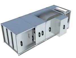
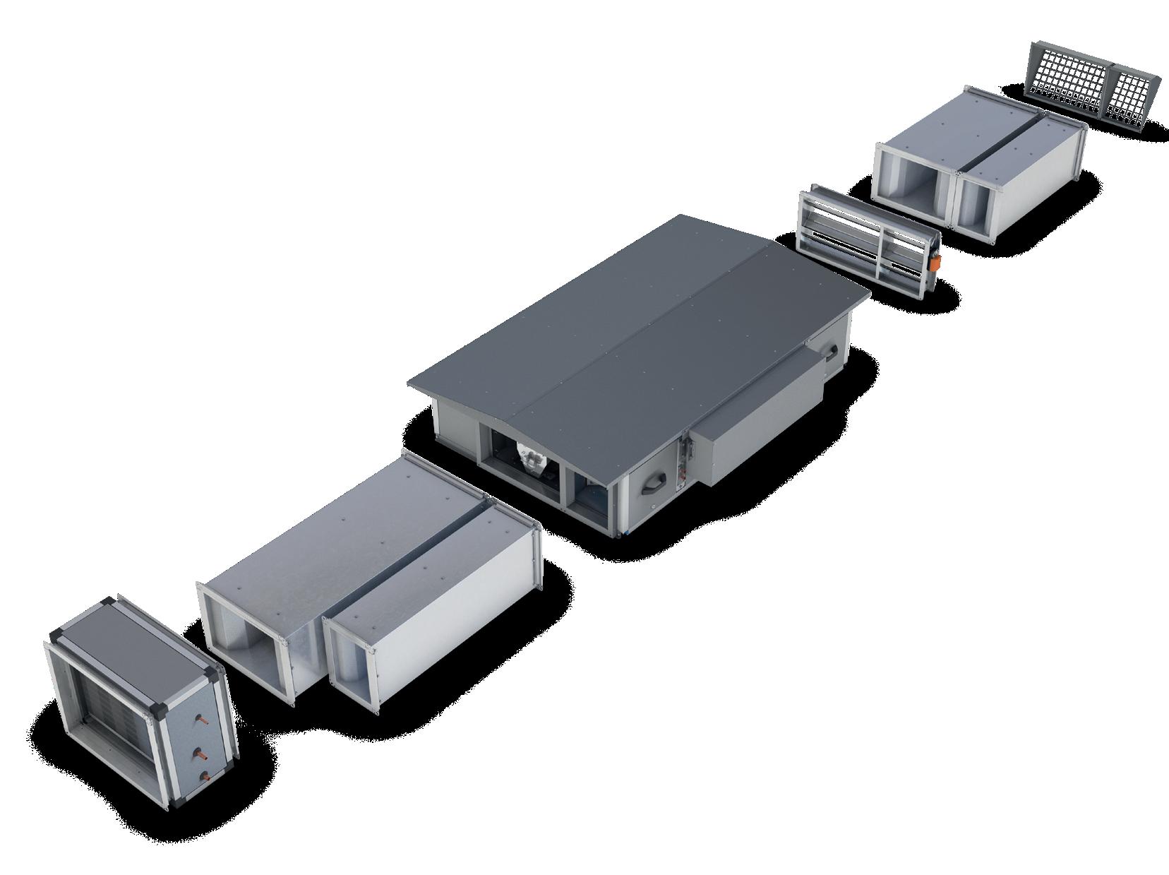
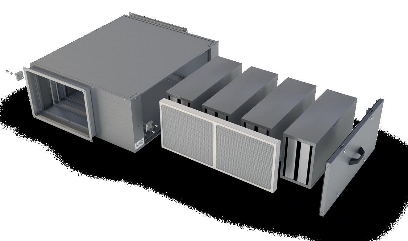
XBOXER XBC+ ANCILLARIES
A wide range of ancillaries and filters are available to meet your specific project requirements.
Ancillaries include matched bend and straight silencers, weather roofs, F7 filters, and the Haven IAQ Module – designed to provide advanced filtration to a system.
MATCHED ANCILLARIES
Designed to seamlessly integrate with any XBC+ system.
ADVANCED FILTRATION
Haven IAQ Module provides filtration from G4 up to F7 or carbon.
SUPERIOR ACOUSTICS
Silencers help reduce noise and are matched for simple installation.
COOLING OPTIONS
Cooling coil modules are available in both chilled water and DX.
Replace ** with required control option: CO - Connect control; AT - Adapt with Trend control. Add ‘4’ to the end of the code for coastal protection coating. Please note, base frames are not included with ancillaries. All ancillaries need to be supported by others.
XBOXER XBC+ PACKAGED HEAT RECOVERY UNITS PIONEERING NEW AIR TECHNOLOGY 38 39
WEATHER ROOF EXHAUST ROOF TERMINAL INTAKE ROOF TERMINAL MOTORISED
MOTORISED
ECOSMART
CONTROL OTHER CONTROLS ECOSMART CLASSIC
CONTROL OTHER CONTROLS XBC10H-WP XBC10-EXHAUST-RT XBC10-INTAKE-RT XBC10-MD XBC10-MD-** XBC10-MD-WP XBC10-MD-**-WP XBC15H-WP XBC15-EXHAUST-RT XBC15-INTAKE-RT XBC15-MD XBC15-MD-** XBC15-MD-WP XBC15-MD-**-WP XBC25H-WP XBC25-EXHAUST-RT XBC25-INTAKE-RT XBC25-MD XBC25-MD-** XBC25-MD-WP XBC25-MD-**-WP XBC45H-WP XBC45-EXHAUST-RT XBC45-INTAKE-RT XBC45-MD XBC45-MD-** XBC45-MD-WP XBC45-MD-**-WP XBC65H-WP XBC65-EXHAUST-RT XBC65-INTAKE-RT XBC65-MD XBC65-MD-** XBC65-MD-WP XBC65-MD-**-WP Please contact Nuaire for more information on our vertical enthalpy units. XBC+ HORIZONTAL INSTALLATION DX / CHILLED WATER COIL MATCHED SILENCERS MATCHED SILENCERS WEATHER ROOF MOTORISED DAMPER EXHAUST ROOF TERMINAL INTAKE ROOF TERMINAL XBC+ UNIT
SELECTION GUIDE
DAMPER (INTERNAL)
DAMPER (EXTERNAL)
CLASSIC AND NO
AND NO
QUICK
STRAIGHT SILENCER DIMENSIONS (MM) - XBC+ 55-65
XBOXER XBC+ 10-65
ANCILLARIES - STRAIGHT SILENCERS
CODING XBC10HS-MS-10
SAMPLE CODING
1. XBOXER XBC+ Range
2. Unit size
3. HE - Intake/Extract HS - Supply/Discharge
4. Matched Silencer 5. 10 - 1050mm length 12 - 1250mm length 16 - 1600mm length
STRAIGHT SILENCER DIMENSIONS (MM) - XBC+ 10-45
QUICK SELECTION GUIDE
Matched attuenuators can be flipped to suit left/right side (1050/1250/1600mm lengths). *Contact Nuaire for details of these variants. Please note, base frames are not included with ancillaries. All ancillaries will need to be supported by others.
XBOXER XBC+ PACKAGED HEAT RECOVERY UNITS PIONEERING NEW AIR TECHNOLOGY 40 41
A B2 C Plan view Side view End view B1 HE HS
XBC 10 – HS – MS – 10 1 2 3 4 5
UNIT SIZE MATCHING SILENCERS S/D (SUPPLY) MATCHING SILENCERS I/E (EXTRACT) 1050MM LONG 1250MM LONG 1600MM LONG 1050MM LONG 1250MM LONG 1600MM LONG Size 10 XBC15-HS-MS10 XBC15-HS-MS12 XBC15-HS-MS16 XBC15-HE-MS10 XBC15-HE-MS12 XBC15-HE-MS16 Size 15 XBC15-HS-MS10 XBC15-HS-MS12 XBC15-HS-MS16 XBC15-HE-MS10 XBC15-HE-MS12 XBC15-HE-MS16 Size 25 XBC25-HS-MS10 XBC25-HS-MS12 XBC25-HS-MS16 XBC25-HE-MS10 XBC25-HE-MS12 XBC25-HE-MS16 Size 45 XBC45-HS-MS10 XBC45-HS-MS12 XBC45-HS-MS16 XBC45-HE-MS10 XBC45-HE-MS12 XBC45-HE-MS16 Size 55 XBC55-HS-MS10 XBC55-HS-MS12 XBC55-HS-MS16 XBC55-HE-MS10 XBC55-HE-MS12 XBC55-HE-MS16 Size 65 XBC65-HS-MS10 XBC65-HS-MS12 XBC65-HS-MS16 XBC65-HE-MS10 XBC65-HE-MS12 XBC65-HE-MS16
CODE DIMENSIONS (mm AIR PATH DYNAMIC INSERTION LOSS (dB WEIGHT (kg) Z’ FACTOR LENGTH A WIDTH B1 WIDTH B2 HEIGHT C 63 125 250 500 1K 2K 4K 8K XBC10-HS-MS10 1050 347 238 220 S / D 5 11 12 19 27 28 24 19 30 1142 XBC10-HE-MS10 / E 2 2 3 10 17 10 6 3 24 622 XBC10-HS-MS12 1250 347 238 220 S / D 7 13 16 26 35 34 27 21 35 1142 XBC10-HE-MS12 / E 4 4 7 17 25 16 9 5 29 622 XBC10-HS-MS16 1600 347 238 220 S / D 9 15 20 33 41 40 30 23 44 1142 XBC10-HE-MS16 / E 6 6 11 24 31 22 12 7 36 622 XBC15-HS-MS10 1050 347 238 220 S / D 5 11 12 19 27 28 24 19 30 1142 XBC15-HE-MS10 / E 2 2 3 10 17 10 6 3 24 622 XBC15-HS-MS12 1250 347 238 220 S / D 7 13 16 26 35 34 27 21 35 1142 XBC15-HE-MS12 / E 4 4 7 17 25 16 9 5 29 622 XBC15-HS-MS16 1600 347 238 220 S / D 9 15 20 33 41 40 30 23 44 1142 XBC15-HE-MS16 / E 6 6 11 24 31 22 12 7 36 622 XBC25-HS-MS10 1050 471 252 302 S / D 5 8 15 30 41 31 21 16 29 468 XBC25-HE-MS10 / E 4 4 10 22 26 15 10 8 29 277 XBC25-HS-MS12 1250 471 252 302 S / D 7 10 18 36 51 39 26 20 34 468 XBC25-HE-MS12 / E 5 6 12 27 34 20 13 9 34 277 XBC25-HS-MS16 1600 471 252 302 S / D 9 13 23 42 55 49 32 25 42 468 XBC25-HE-MS16 / E 6 8 15 33 43 25 15 11 42 277 XBC45-HS-MS10 1050 531 270 360 S / D 5 9 16 13 11 8 7 6 32 80 XBC45-HE-MS10 / E 3 5 11 13 15 11 6 4 32 205 XBC45-HS-MS12 1250 531 270 360 S / D 7 11 20 20 19 14 10 8 40 80 XBC45-HE-MS12 / E 5 7 15 20 23 17 9 6 37 205 XBC45-HS-MS16 1600 531 270 360 S / D 9 13 24 27 25 20 13 10 47 80 XBC45-HE-MS16 / E 7 9 19 27 29 23 12 8 47 205 CODE DIMENSIONS mm) AIR PATH DYNAMIC INSERTION LOSS (dB) WEIGHT kg) Z’ FACTOR LENGTH A WIDTH B1 WIDTH B2 HEIGHT C 63 125 250 500 1K 2K 4K 8K XBC55-HS-MS10 1050 588 398 430 S / D 4 10 17 19 23 18 15 11 32 108 XBC55-HE-MS10 E 3 6 12 15 15 11 6 4 36 84 XBC55-HS-MS12 1250 588 398 430 S / D 6 12 21 26 31 24 18 13 37 108 XBC55-HE-MS12 E 5 8 16 22 23 17 9 6 42 136 XBC55-HS-MS16 1600 588 398 430 S / D 8 14 25 33 37 30 21 15 47 108 XBC55-HE-MS16 E 7 10 20 29 29 23 12 8 52 136 XBC65-HS-MS10 1050 588 398 580 S / D 4 11 14 23 23 22 14 9 43 89 XBC65-HE-MS10 E 3 8 12 15 10 6 3 2 46 78 XBC65-HS-MS12 1250 588 398 580 S / D 6 13 18 30 31 28 17 11 51 89 XBC65-HE-MS12 E 5 10 16 22 18 12 6 4 54 78 XBC65-HS-MS16 1600 588 398 580 S / D 8 15 22 37 37 34 20 13 63 89 XBC65-HE-MS16 E 7 12 20 29 24 18 9 6 67 78
ACOUSTIC BEND ATTENUATOR COMBINATION EXAMPLES
XBOXER XBC+ 10-65
ANCILLARIES - BEND SILENCERS
Where to use bend attenuators. Bend matched silencers are ideal for projects where space is limited and the straight matched silencers cannot be fitted. The bend silencers are fitted with the matching flange at either end allow for additional straight silencers to also be added if required.
XBC10 - 65
HORIZONTAL UNITS BEND ATTENUATOR DIMENSIONS
BEND SILENCER CODING 1. XBOXER XBC Range
size: 15, 25, 45, 55 or 65
4. Matched Bend Silencer
5. S = Short (refer to dimensions)
= Long (refer to dimensions)
XBC+ 10-65 BEND SILENCER - DIMENSIONS (mm)
XBC+ 10-65 BEND SILENCER - SOUND DATA
XBOXER XBC+ PACKAGED HEAT RECOVERY UNITS PIONEERING NEW AIR TECHNOLOGY 42 43
XBC+ UNIT SIZE ATTENUATOR CODE ATTENUATOR DIMENSIONS DYNAMIC INSERTION LOSS (dB) ATTENUATOR WEIGHT (kg) ‘Z’ FACTOR A B C D E F G H I 63 125 250 500 1000 2000 4000 8000 XBC+ 10 XBC15-HS-MBS-S 515 496 322 515 496 260 220 386 346 2 4 9 17 30 33 25 19 36 900.0 XBC15-HS-MBS-L 852 833 659 515 496 260 220 386 346 2 5 12 22 38 39 28 22 46 1100.0 XBC15-HE-MBS-S 406 387 268 406 387 260 220 277 237 2 4 10 18 32 35 25 20 36 2000.0 XBC15-HE-MBS-L 852 833 714 406 387 260 220 277 237 3 5 13 24 42 41 29 23 44 2300.0 XBC+ 15 XBC15-HS-MBS-S 515 496 322 515 496 260 220 386 346 2 4 9 17 30 33 25 19 36 2300.0 XBC15-HS-MBS-L 852 833 659 515 496 260 220 386 346 2 5 12 22 38 39 28 22 46 2300.0 XBC15-HE-MBS-S 406 387 268 406 387 260 220 277 237 2 4 10 18 32 35 25 20 36 2300.0 XBC15-HE-MBS-L 852 833 714 406 387 260 220 277 237 3 5 13 24 42 41 29 23 44 2300.0 XBC+ 25 XBC25-HS-MBS-S 640 621 385 640 621 342 302 511 471 2 4 8 16 29 22 14 10 50 156.3 XBC25-HS-MBS-L 992 973 737 640 621 342 302 511 471 2 5 10 21 38 25 17 13 64 173.6 XBC25-HE-MBS-S 421 402 275 421 402 342 302 292 252 2 4 8 16 29 22 14 10 40 208.3 XBC25-HE-MBS-L 992 973 846 421 402 342 302 292 252 2 5 10 38 25 17 13 50 54 225.7 XBC+ 45 XBC45-HS-MBS-S 700 681 415 700 681 400 360 571 531 3 6 9 17 29 21 13 7 60 116.9 XBC45-HS-MBS-L 1070 1051 785 700 681 400 360 571 531 4 7 10 21 37 26 15 8 76 116.9 XBC45-HE-MBS-S 439 420 284 439 420 400 360 310 270 3 6 9 17 29 21 13 7 42 146.1 XBC45-HE-MBS-L 1070 1051 915 439 420 400 360 310 270 4 7 10 21 37 26 15 8 58 160.7 XBC+ 55 XBC55-HS-MBS-S 756 737 443 756 737 470 430 627 587 3 7 10 21 37 26 15 8 68 80.0 XBC55-HS-MBS-L 1253 1234 940 756 737 470 430 627 587 4 10 18 31 39 24 12 7 96 92.0 XBC55-HE-MBS-S 566 547 348 566 547 470 430 437 397 3 6 10 18 24 16 9 6 48 80.0 XBC55-HE-MBS-L 1253 1234 1035 566 547 470 430 437 397 4 10 18 31 39 24 12 7 72 100.0 XBC+ 65 XBC65-HS-MBS-S 756 737 443 756 737 620 580 627 587 3 8 14 23 22 14 7 4 76 44.4 XBC65-HS-MBS-L 1253 1234 940 756 737 620 580 627 587 14 10 19 31 30 18 9 5 106 50.0 XBC65-HE-MBS-S 566 547 348 566 547 620 580 437 397 3 8 14 23 22 14 7 4 54 55.6 XBC65-HE-MBS-L 1253 1234 1035 566 547 620 580 437 397 4 10 19 31 30 18 9 5 86 63.9
Matching flange is supplied attached to all XBC units. Note: Air Pressure Drop of Attenuator (Pa) = Z*Q^2 where Z = Factor listed in table above Pa/Q^2. Coding: HS - denotes the type of silencer required for the supply or discharge. HE - denotes the type of silencer required for the extract or intake. Note: XBC15 silencers are also suitable for XBC10 units. Side view HS-MBS-S HS-MBS-L HE-MBS-L HE-MBS-S HS HE HS HE A B C D E C H F G Duct Connection Duct Connection XBC Connection Plan view XBC Connection
3.
2. Unit
HE = Extract/Intake HS = Supply/Discharge
1 2 3 4 5 Plan view Suppy Extract Intake Dischage Intake Discharge Ext ac Supply Intake Dischage Extract Suppy Suppy Ext ac ntake Dischage Ex ract Suppy Discharge Discharge Ex ract Suppy ntake ntake
L
XBC+ 15 - HE - MBS - S
HAVEN IAQ MODULE
Indoor air quality has always been at the core of our thinking. Haven leads the way in filtration solutions, ensuring maximum occupant comfort and wellbeing.
The Haven IAQ Module is an in-line duct-mounted filtration solution, allowing for advanced filtration to a space. Modules have multiple filter options – from G4 (Coarse 78%) all the way up to activated carbon. Modules are matched for use with the XBC+ range but can be used as an in-duct filtration solution with other Nuaire ranges, such as DAVE Supply.
CODING HIAQM-015-S-A-A-1W
1. Haven IAQ Module.
2. Module size.
3. S – Side access.
B – Bottom access.
4. Primary stage panel filter (see filter options).
5. Secondary stage bag filter (see filter options).
6. 1 – Standard Magnelis®* finish.
4 – Coastal (C4*) finish.
7. 1 – Standard unit (no roof).
W – Twin-pitched roof (factory fitted).
*This units coastal finish has been designed to withstand an External C4 Atmospheric Corrosivity Category as per BS EN ISO 12944-2:2017 providing that it is installed and maintained as per the manufacturer’s instructions and general Warranty
Notes found in our conditions of sale.
FILTER OPTIONS
CODING HIAQM-015-S-A-A-1W
Primary stage panel filter
Secondary stage bag filter
MODULE SHOWN WITH CARBON FILTRATION OPTION. Carbon filtration available with side access units only.
D
MODULE SHOWN WITH BOTTOM ACCESS
E
G Rigid carbon panel unit (RCP)
H No Filter
CONSULTANT SPECIFICATION
OPERATION
CLEANER AIR
Advanced filtration aids in achieving higher levels of indoor air quality (IAQ).
LOW DEPTH
Ideal for projects with space restrictions or shallow ceiling voids.
HIGH CLASSIFICATION
Tested to meet L2 leakage and F9 filter bypass leakage.
RETROFIT SOLUTION
Can be added later to help stop outside pollutants entering the space.
PROJECT SPECIFIC
Various filter options available allowing you to specify to your project requirements.
The Haven IAQ Module range of ancillaries has been specially designed to complement the existing range of XBC+ units as well as providing a general function of high-grade filtration to any commercial ventilation units which require it. The unit shall be manufactured from Magnelis®* with double-skin panels filled with insulation to provide thermal and acoustic barriers. The units will come as standard with pressure monitoring for the filtration and give a relay output for alarm signalling when a pre-determined pressure value is exceeded. The units will be available with different access options (bottom or side access) as well as weatherproofing and coastal varieties depending on installation location. The unit is unhanded with different operations to suit it for different installations (please refer to I&M for details).
Bag and panel filter weights negligible, please contact Nuaire for more information.
XBOXER XBC+ PACKAGED HEAT RECOVERY UNITS PIONEERING NEW AIR TECHNOLOGY 44 45
PERFORMANCE & TECHNICAL INFORMATION DIMENSIONS (mm) & WEIGHT (kg) WEATHERPROOF ROOF OPTION CARBON FILTER WEIGHT (kg) MODULE CASING BRACKET CENTRES FLANGE CONNECTIONS TOTAL LENGTH TOTAL WIDTH WEIGHT A B C D E F G H J* MODULE CARBON FILTER TOTAL Size 15 890 665 259 755 690 351 218 1010 727 28 22 50 Size 25 990 809 339 855 830 481 298 1110 868 34 41 75 Size 45 990 885 399 855 907 536 358 1110 944 45 56 101 Size 55 990 1068 469 855 1090 592 428 1110 1127 55.4 75.6 131 Size 65 890 1068 622 755 1090 592 578 1010 1127 64 87 151 MODULE A B C WEIGHT Size 15 902 695 334 60 Size 25 1002 839 424 88 Size 45 1002 915 489 116 Size 55 1002 1098 574 148 Size 65 902 1098 727 168 WEIGHT 22 41 56 75.6 87 CODING HIAQM-015-1A-FILTER SPARE FILTERS 1. Haven IAQ Module. 2. Module size. 3. 1 – Primary stage panel filter. 2 – Secondary stage bag filter. 4. Filter (see filter options). 5. Replacement filter. HIAQM – 015 – 1 A – FILTER 1 2 3 4 5 EXAMPLE UNIT: SIDE ACCESS UNIT WITH WEATHER ROOF EXAMPLE UNIT: BOTTOM ACCESS INTERNAL UNIT A A H H E F F J J G G B B D C C *Minus 20mm to dimension B for bottom access units.
HIAQM – 015 – S – A – A – 1 W 1 2 3 4 5 6 7
Guidance
CODING FILTER TYPE
G4 / ISO coarse
M5 / ePM10 50%
M6 / ePM2.5 50%
A
B
C
F7
ePM1
/
50%
F8
ePM1
F9 ePM1
/
70% F
80%
HAVEN IAQ MODULES
of HIAQM-025 – F7 Primary stage filter @ 0.25m3/s is 51 Pa
of HIAQM-025 – Carbon Secondary stage filter @ 0.25m3/s is 77 Pa
resistance of HIAQM-025-S-D-G-11 @ 0.25m3/s is 128 Pa
= (827*1229)*(0.25)^2 = 128 Pa
HAVEN IAQ MODULES RESISTANCE DATA
XBOXER XBC+ PACKAGED HEAT RECOVERY UNITS PIONEERING NEW AIR TECHNOLOGY 46 47 0 20 40 60 80 100 140 160 180 0 0.1 0.2 0.3 0.4 0.5 0.6 Resistance (Pa) Flowrate (m3/s 200 120 0.7 FILTER RESISTANCE - HIAQM-065 HIAQM-065 Panel Filter HIAQM-065 Carbon Filter HIAQM-065-S-D-G-11 FILTER RESISTANCE - HIAQM-045 HIAQM-045 Panel Filter HIAQM-045 Carbon Filter HIAQM-045-S-D-G-11 0 50 100 200 180 0 0.1 0.4 0.2 0.5 0.3 Resistance (Pa) Flowrate (m3/s) 250 150 300 0 20 40 60 80 100 140 160 180 0 0.05 0.1 0.2 0.3 0.4 0.5 0.6 Resistance (Pa) Flowrate (m3/s) 200 120 FILTER RESISTANCE - HIAQM-055 HIAQM-055 Panel Filter HIAQM-055 Carbon Filter HIAQM-055-S-D-G-11
RESISTANCE DATA MODULE A B C D E F XBC15 1083 1818 1939 2303 3345 3296 XBC25 396 653 697 827 1215 1202 XBC45 228 438 467 554 806 806 XBC55 106 204 218 259 376 376 XBC65 58 113 120 143 207 207 Z FACTORS R=Z*Q2 MODULE A B C D E F G XBC15 1054 1555 1568 2634 3535 3995 2126 XBC25 421 627 564 873 1286 1465 1229 XBC45 404 605 375 495 768 824 761 XBC55 183 274 175 231 358 384 361 XBC65 93 137 96 125 197 210 179 SECONDARY FILTERS EXAMPLE
R
Resistance
Resistance
Combined
R
0 20 40 60 80 100 140 160 180 0 0.05 0.1 0.15 0.2 0.25 0.3 Resistance (Pa) Flowrate (m3/s 200 120 FILTER RESISTANCE - HIAQM-025 HIAQM-025 Panel Filter HIAQM-025 Carbon Filter HIAQM-025-S-D-G-11 0 50 100 200 180 0 0.05 0.1 0.15 0.2 0.25 0.3 0.35 Resistance (Pa) Flowrate (m3/s) 250 150 300 FILTER RESISTANCE - HIAQM-015 HIAQM-015 Panel Filter HIAQM-015 Carbon Filter HIAQM-015-S-D-G-11 FILTER TYPE G4 / ISO coarse M5 / ePM10 50% M6 / ePM2.5 50% F7 / ePM1 50% F8 ePM1 70% F9 / ePM1 80% Rigid carbon panel unit (RCP) No Filter
FROM THE GRAPH
= Z*Q2 Q = airflow in m³/s
XBOXER XBC+ 10-65 ANCILLARIES – COOLING COIL MODULES
XBC+ units are available with bolt-on cooling modules as a matched ancillary. Cooling coil modules are available in both DX and chilled water cooling options.
CODING XBC25H-DX-DUCTM-LWP CODING XBC25H-CW-DUCTM-LWP
SAMPLE CODING
1. XBOXER range
2. C – Counter flow heat exchanger
3. Unit size
4. H – Horizontal layout
5. DX – Direct expansion cooling
6. DUCT – Duct-mounted module
7. M – For use with Mitsubishi condenser*
O – For use with other manufacturer condenser
8. L – Left controls handing
R – Right controls handing
9. WP – Weather roof (optional)
* Controls, sensors, piping and gas by others.
CHILLED WATER COOLING COILS
Chilled water coil shall be manufactured from copper tubing with high efficiency aluminium fins contained within a galvanised steel frame. Coil supplied complete with an insulated condensate tray and moisture eliminator. All components prepiped, assembled and tested by the manufacturer.
SAMPLE CODING
1. XBOXER range
2. C – Counter flow heat exchanger
3. Unit size
4. H – Horizontal layout
5. CW – Chilled water cooling
6. DUCT – Duct-mounted module
7. L – Left controls handing
R – Right controls handing
8. WP – Weather roof (optional)
DX (DIRECT EXPANSION) COOLING COILS
DX coil shall be manufactured from copper tubing with high efficiency aluminium fins and droplet eliminator contained within a galvanised steel frame where applicable. The coil shall be filled with dry nitrogen with the pipe connections capped. It shall be factory fitted and tested by Nuaire.
DX COOLING MODULE DIMENSIONS (mm) AND WEIGHT (kg)
CHILLED WATER COOLING MODULE DIMENSIONS (mm) AND WEIGHT (kg)
Replace * with L for left controls handing units and R for right controls handing units.
* with L for left controls handing units and R for right controls handing units.
XBOXER XBC+ PACKAGED HEAT RECOVERY UNITS PIONEERING NEW AIR TECHNOLOGY 48 49
XB C 25 H – DX – DUCT M – L WP 1 2 3 4 5 6 7 8 9 XB C 25 H – CW – DUCT L – WP 1 2 3 4 5 6 7 8 A B C CODE A B C WEIGHT XBC10H-DX-DUCTM-* 325 390 365 12 XBC10H-DX-DUCTO-* 425 460 370 16 XBC10H-DX-DUCTM-*WP 325 390 390 13 XBC10H-DX-DUCTO-*WP 425 460 400 18 XBC15H-DX-DUCTM-* 325 440 415 14 XBC15H-DX-DUCTO-* 670 460 370 23 XBC15H-DX-DUCTM-*WP 325 440 443 15 XBC15H-DX-DUCTO-*WP 670 460 400 26 XBC25H-DX-DUCTM-* 375 650 465 20 XBC25H-DX-DUCTO-* 670 580 450 28 XBC25H-DX-DUCTM-*WP 375 650 506 22 XBC25H-DX-DUCTO-*WP 670 580 487 32 XBC45H-DX-DUCTM-* 375 690 545 23 XBC45H-DX-DUCTO-* 643 640 500 30 XBC45H-DX-DUCTM-*WP 375 690 590 25 XBC45H-DX-DUCTO-*WP 643 640 542 34 XBC55H-DX-DUCTM-* 375 665 620 23 XBC55H-DX-DUCTO-* 643 690 580 34 XBC55H-DX-DUCTM-*WP 375 665 663 25 XBC55H-DX-DUCTO-*WP 643 690 624 38 XBC65H-DX-DUCTM-* 375 765 670 26 XBC65H-DX-DUCTO-* 643 690 730 38 XBC65H-DX-DUCTM-*WP 375 765 719 28 XBC65H-DX-DUCTO-*WP 643 690 774 41
CODE A B C WEIGHT XBC10H-CW-DUCT-* 425 460 370 16 XBC10H-CW-DUCT-*WP 425 460 400 18 XBC15H-CW-DUCT-* 670 460 370 23 XBC15H-CW-DUCT-*WP 670 460 400 26 XBC25H-CW-DUCT-* 670 580 450 28 XBC25H-CW-DUCT-*WP 670 580 487 32 XBC45H-CW-DUCT-* 643 640 500 30 XBC45H-CW-DUCT-*WP 643 640 542 34 XBC55H-CW-DUCT-* 643 690 580 34 XBC55H-CW-DUCT-*WP 643 690 624 38 XBC65H-CW-DUCT-* 643 690 730 38 XBC65H-CW-DUCT-*WP 643 690 774 41
Replace
DX COIL DATA
TECHNICAL INFORMATION
XBOXER XBC+ PACKAGED HEAT RECOVERY UNITS PIONEERING NEW AIR TECHNOLOGY 50 51
SIZE 15 COIL INFORMATION AIR INFORMATION REFRIGERANT R410A Reverse Cycle DX Coil Internal Coil Volume (l) Evaporating Temperature (°C) Condensing Temperature (°C) Airflow Rate (%) Airflow Rate (l/s) Air Temperature Before Coil (°C) Air Humidity Before Coil (%RH) Air Temperature After Coil (°C) Air Humidity After Coil (%RH) Total Cooling Output (kW) Sensible Cooling Output (kW) Moisture Extraction Rate (kg/hr) 1.1 9 40 100% 0.17 28.0 50.0 16.90 93.0 2.7 2.3 0.5 75% 0.13 28.0 50.0 16.00 95.0 2.3 1.9 0.6 50% 0.09 28.0 50.0 15.00 97.0 1.8 1.4 0.6 SIZE 25 COIL INFORMATION AIR INFORMATION REFRIGERANT R410A Reverse Cycle DX Coil Internal Coil Volume (l) Evaporating Temperature (°C) Condensing Temperature (°C) Airflow Rate (%) Airflow Rate (l/s) Air Temperature Before Coil (°C) Air Humidity Before Coil (%RH) Air Temperature After Coil (°C) Air Humidity After Coil (%RH) Total Cooling Output (kW) Sensible Cooling Output (kW) Moisture Extraction Rate (kg/hr) 2.4 9 40 100% 0.25 28.0 50.0 15.20 95.0 5.2 3.9 1.7 75% 0.19 28.0 50.0 14.60 96.0 4.2 3.1 1.5 50% 0.13 28.0 50.0 14.20 97.0 3.0 2.2 1.1 SIZE 45 COIL INFORMATION AIR INFORMATION REFRIGERANT R410A Reverse Cycle DX Coil Internal Coil Volume (l) Evaporating Temperature (°C) Condensing Temperature (°C) Airflow Rate (%) Airflow Rate (l/s) Air Temperature Before Coil (°C) Air Humidity Before Coil (%RH) Air Temperature After Coil (°C) Air Humidity After Coil (%RH) Total Cooling Output (kW) Sensible Cooling Output (kW) Moisture Extraction Rate (kg/hr) 2.4 9 40 100% 0.37 28.0 50.0 16.20 93.0 6.6 5.3 1.8 75% 0.28 28.0 50.0 15.40 94.0 5.6 4.3 1.8 50% 0.19 28.0 50.0 14.80 95.0 4.2 3.0 1.5 SIZE 55 COIL INFORMATION AIR INFORMATION REFRIGERANT R410A Reverse Cycle DX Coil Internal Coil Volume (l) Evaporating Temperature (°C) Condensing Temperature (°C) Airflow Rate (%) Airflow Rate (l/s) Air Temperature Before Coil (°C) Air Humidity Before Coil (%RH) Air Temperature After Coil (°C) Air Humidity After Coil (%RH) Total Cooling Output (kW) Sensible Cooling Output (kW) Moisture Extraction Rate (kg/hr) 2.4 9 40 100% 0.55 28.0 50.0 16.20 93.0 9.7 7.8 2.5 75% 0.41 28.0 50.0 15.80 95.0 7.7 6.1 2.4 50% 0.28 28.0 50.0 15.10 96.0 5.8 4.4 1.8 SIZE 65 COIL INFORMATION AIR INFORMATION REFRIGERANT R410A Reverse Cycle DX Coil Internal Coil Volume (l) Evaporating Temperature (°C) Condensing Temperature (°C) Airflow Rate (%) Airflow Rate (l/s) Air Temperature Before Coil (°C) Air Humidity Before Coil (%RH) Air Temperature After Coil (°C) Air Humidity After Coil (%RH) Total Cooling Output (kW) Sensible Cooling Output (kW) Moisture Extraction Rate (kg/hr) 4.6 9 40 100% 0.60 28.0 50.0 15.70 94.0 11.4 8.7 3.6 75% 0.45 28.0 50.0 15.10 95.0 9.2 6.9 3.2 50% 0.30 28.0 50.0 14.70 96.0 6.5 4.7 2.4
XBC+ CHILLED WATER COIL DATA
TECHNICAL INFORMATION
XBOXER XBC+ PACKAGED HEAT RECOVERY UNITS PIONEERING NEW AIR TECHNOLOGY 52 53
SIZE 15 COIL INFORMATION AIR INFORMATION FLOW / RETURN TEMPERATURES (°C) 6 / 12 7 / 14 CHW Coil Connection Size (“) Airflow Rate (%) Airflow Rate (l/s) Air Temperature Before Coil (°C) Air Humidity Before Coil (%RH) Air Temperature After Coil (°C) Air Humidity After Coil (%RH) Total Cooling Output (kW) Sensible Cooling Output (kW) Water Flowrate (l/s) Water Pressure Drop (kPa) Moisture Extraction Rate (kg/hr) Air Temperature After Coil (°C) Air Humidity After Coil (%RH) Total Cooling Output (kW) Sensible Cooling Output (kW) Water Flowrate (l/s) Water Pressure Drop (kPa) Moisture Extraction Rate (kg/hr) 1/2” 100% 0.17 28.0 50.0 17.4 85.1 2.80 2.2 0.10 17.4 1.0 18.5 84.7 2.30 2.0 0.10 8.5 0.5 75% 0.13 28.0 50.0 16.4 88.0 2.50 1.8 0.10 13.6 1.0 17.6 87.5 2.00 1.6 0.10 6.7 0.5 50% 0.09 28.0 50.0 15..4 90.6 1.90 1.4 0.10 8.4 0.8 16.8 90.0 1.50 1.2 0.10 4.1 0.5 SIZE 25 COIL INFORMATION AIR INFORMATION FLOW / RETURN TEMPERATURES (°C) 6 / 12 7 / 14 CHW Coil Connection Size (“) Airflow Rate (%) Airflow Rate (l/s) Air Temperature Before Coil (°C) Air Humidity Before Coil (%RH) Air Temperature After Coil (°C) Air Humidity After Coil (%RH) Total Cooling Output (kW) Sensible Cooling Output (kW) Water Flowrate (l/s) Water Pressure Drop (kPa) Moisture Extraction Rate (kg/hr) Air Temperature After Coil (°C) Air Humidity After Coil (%RH) Total Cooling Output (kW) Sensible Cooling Output (kW) Water Flowrate (l/s) Water Pressure Drop (kPa) Moisture Extraction Rate (kg/hr) 1/2” 100% 0.25 28.0 50.0 15.4 89.6 5.40 3.8 0.20 15.9 2.3 16.6 89.0 4.50 3.4 0.20 8.5 1.5 75% 0.19 28.0 50.0 14.8 91.2 4.40 3.0 0.20 10.8 2.1 16.1 90.5 3.70 2.7 0.10 5.8 1.3 50% 0.13 28.0 50.0 14.2 82.7 3.20 2.2 0.10 6.1 1.4 15.6 92.1 2.60 1.9 0.10 3.2 0.9 SIZE 45 COIL INFORMATION AIR INFORMATION FLOW RETURN TEMPERATURES (°C) 6 / 12 7 / 14 CHW Coil Connection Size (“) Airflow Rate (%) Airflow Rate (l/s) Air Temperature Before Coil (°C) Air Humidity Before Coil (%RH) Air Temperature After Coil (°C) Air Humidity After Coil (%RH) Total Cooling Output (kW) Sensible Cooling Output (kW) Water Flowrate (l/s) Water Pressure Drop (kPa) Moisture Extraction Rate (kg/hr) Air Temperature After Coil (°C) Air Humidity After Coil (%RH) Total Cooling Output (kW) Sensible Cooling Output (kW) Water Flowrate (l/s) Water Pressure Drop (kPa) Moisture Extraction Rate (kg/hr) 1/2” 100% 0.37 28.0 50.0 16.6 86.8 7.00 5.1 0.30 21.2 2.7 17.7 86.3 5.70 4.6 0.20 11.4 1.6 75% 0.28 28.0 50.0 15.9 88.7 5.80 4.1 0.20 15.5 2.4 17.1 88.1 4.70 3.7 0.20 8.1 1.5 50% 0.19 28.0 50.0 12.1 90.6 4.20 3.0 0.20 8.8 1.8 16.4 89.9 3.50 2.7 0.10 4.7 1.2 SIZE 55 COIL INFORMATION AIR INFORMATION FLOW RETURN TEMPERATURES (°C) 6 / 12 7 / 14 CHW Coil Connection Size (“) Airflow Rate (%) Airflow Rate (l/s) Air Temperature Before Coil (°C) Air Humidity Before Coil (%RH) Air Temperature After Coil (°C) Air Humidity After Coil (%RH) Total Cooling Output (kW) Sensible Cooling Output (kW) Water Flowrate (l/s) Water Pressure Drop (kPa) Moisture Extraction Rate (kg/hr) Air Temperature After Coil (°C) Air Humidity After Coil (%RH) Total Cooling Output (kW) Sensible Cooling Output (kW) Water Flowrate (l/s) Water Pressure Drop (kPa) Moisture Extraction Rate (kg/hr) 1/2” 100% 0.55 28.0 50.0 16.4 87.5 9.60 7.0 0.40 18.2 3.9 17.6 86.9 7.80 6.3 0.30 10.4 2.2 75% 0.41 28.0 50.0 15.8 89.1 7.90 5.6 0.30 12.7 3.4 17.0 88.6 6.50 5.1 0.20 7.4 2.1 50% 0.28 28.0 50.0 15.0 91.0 5.60 3.9 0.20 7.6 2.7 16.4 90.4 4.60 3.5 0.10 4.0 1.7 SIZE 65 COIL INFORMATION AIR INFORMATION FLOW / RETURN TEMPERATURES (°C) 6 / 12 7 / 14 CHW Coil Connection Size (“) Airflow Rate (%) Airflow Rate (l/s) Air Temperature Before Coil (°C) Air Humidity Before Coil (%RH) Air Temperature After Coil (°C) Air Humidity After Coil (%RH) Total Cooling Output (kW) Sensible Cooling Output (kW) Water Flowrate (l/s) Water Pressure Drop (kPa) Moisture Extraction Rate (kg/hr) Air Temperature After Coil (°C) Air Humidity After Coil (%RH) Total Cooling Output (kW) Sensible Cooling Output (kW) Water Flowrate (l/s) Water Pressure Drop (kPa) Moisture Extraction Rate (kg/hr) 1/2” 100% 0.60 28.0 50.0 16.1 88.2 11.90 8.6 0.50 17.0 4.8 17.3 87.6 9.70 7.8 0.30 9.0 2.9 75% 0.45 28.0 50.0 15.5 89.7 9.60 9.6 0.40 11.6 4.0 16.8 89.1 7.80 6.1 0.30 7.3 2.5 50% 0.30 28.0 50.0 14.9 91.4 6.80 6.8 0.30 7.5 3.0 16.3 90.7 5.50 4.2 0.20 4.1 1.9
XBOXER XBC+ 10-65 CONSULTANT SPECIFICATION
OPERATION
The supply and extract ventilation unit shall be configured as indicated on the drawings. The heat recovery ventilation unit shall enable the room design conditions to be maintained by the effective and continuous control of ventilation rate, the integrated counterflow heat exchanger matrix with bypass feature, and heating facility. The ventilation unit shall automatically vary the ventilation rate in the space dependent upon the signals received from the interconnected sensors and user interface (where provided). When signals are received, the unit shall vary its fan speeds proportionally until the desired set points are met. The unit shall have the facility to commission the supply and extract fans individually via inbuilt maximum, minimum and offset speed adjustments. Each fan shall have stepless variable speed control (20 – 100% of maximum). The unit shall be the XBC+ 10-65 as manufactured by Nuaire.
UNIT SPECIFICATION
The heat recovery ventilation unit will be selected from the ‘XBOXER XBC+ packaged heat recovery range’ as manufactured by Nuaire in one of the available sizes from XBC10-65.
The unit will be unit constructed from corrosion resistant Magnelis®* supported by a bespoke anodised aluminium extrusion system. The standard panel execution will be in a ‘natural’ Magnelis®* finish or as a painted panel option to a specified RAL colour. On request, the XBC+ will also have the option of additional corrosion protection to withstand an External C4 Atmospheric Corrosivity Category Environment as per BS EN ISO 12944-2:2017 when installed as per the manufacturers recommendations. The Atmospheric Corrosivity Environment should be determined using BS EN ISO 9223:2012 and BS EN ISO 14713-1:2009.
The heat recovery ventilation unit together with matching silencers shall have a maximum depth of 260 / 346 / 405 / 470 / 624 mm (Models XBC+ 10-65). The ventilation unit and attenuators shall have an asymmetric, high mass double skinned wall construction (patent applied for) with integral acoustic barrier mat* ensuring low breakout noise levels. The unit and attenuators shall be supplied complete with suspension brackets for inclusion into a drop rod mounting system. The unit shall incorporate a high efficiency aluminium counterflow plate heat exchanger matrix with a thermal efficiency of up to 96%, fitted with a segmented 100% bypass facility and patented actuator operating under automatic control. The automatic operation of the XBC+ bypass is determined by an algorithm that varies output based on temperatures, and whether the control system has been set to prioritise heating, ventilation or cooling. All elements of the unit shall be protected from airborne contamination by high capacity pleated G4 (EN779:2012) / ISO Coarse 75% (ISO 16890) panel filters (supply and extract). Two spare filters are provided within the unit for post-construction phase fitting. The unit shall be fitted with ErP 2018 rated, low energy, high efficiency IP54 EC motorised fans providing low specific fan powers and stepless speed control, without tonal noise generation.
Fan/motor assemblies have sealed for life bearings with an anticipated working life of 70,000 hours (L10) and shall be suitable for single phase supply. Impellers shall be of high efficiency, performance and sound optimised backward curved design. The unit shall be fitted with either an electric heater battery with burst fired temperature controller; or a LPHW heater battery complete with factory fitted valve and actuator, terminating at the unit casing. Both LPHW and Electric heater variants will be available in ‘high’ and ‘low’ duty heater options allowing the unit to be better matched to the specified heating load. The system shall have frost protection (Ecosmart models only) which shall, at temperatures below 4 degrees C, fully open the 4-port valve and only start the fan when the temperature within the chamber has risen above the designated set point. The LPHW assembly shall be pressure tested at works to a minimum of 6 Bar. The control for the heaters shall be fully integrated and shall maintain a constant temperature*** to meet the system design requirements. The unit is also available without a heater fitted. The unit shall be constructed with removable side panels allowing maintenance access with minimal service space clearance required. The unit shall also be available in a bottom access variant providing access for routine filter maintenance.
The removable panels shall provide access to the following:-
• Supply and extract fan.
• Supply and extract filter.
• Condensate tray.
• All control adjustments (where included). Bottom access variants are available (for filter access only).
UNIT CONFIGURATION
Supply/discharge airflow connections are on the unit centreline; Intake/Extract connections are configurable on site to either side of the unit. Unit is supplied as configuration A as standard (refer to technical documentation). The ventilation unit shall comprise the following:- Supply and extract fans; high efficiency counterflow plate heat exchanger matrix also available as an Enthalpy variant; supply and extract filters; full 100% automatic heat exchanger bypass; heating coil (as selected) & condensate drip tray; a condensate pump is installed in the unit and has an alarm function (connection by others).
If the water level in the condensate tray exceeds a maximum level (for example, as a result of the discharge tube becoming blocked or frozen), the alarm contact will open. This contact is internally connected to the heat exchanger bypass actuator, and the unit will automatically be placed into bypass mode, preventing further condensate production. Unit operation will otherwise be unaffected.
Matching high mass double skinned wall construction attenuators can also be provided by Nuaire. For further details on the ErP directive please refer to www.nuaire.co.uk
NO CONTROL OPTION
Unit is provided with side access terminal boxes for direct supply and extract fan motor wiring and for interfacing to custom built control panels. The control assembly is side mounted with a 90° rotation facility for wiring and commissioning adjustments in restricted access conditions. (260mm access allowance is required). A side mounted terminal box is provided for the connections to the fans (230V 50Hz LNE and 2-10V), and Electric heater terminal and thermal protection (where specified). For this option, no sensors are fitted to the unit, but note that the plate heat exchanger bypass damper actuator is included suitable for 230V standard (24V available).
Units fitted with ‘No Control’ option have a 2 year warranty: first year parts & labour and then the remaining year parts only.
ECOSMART CLASSIC OPTIONDEMAND CONTROLLED VENTILATION
Provides the facility for energy saving via an intelligent stand-alone AHU function with local diagnostic status indication, or allows convenient integration with the client BMS with a minimal coordination requirement. The factory fitted Ecosmart Classic control includes:- integral infinitely variable speed / duty control for the supply and extract fans, with independent minimum, maximum and offset adjustment (up to 40%) for accurate commissioning. The control assembly is side mounted with a 90° rotation facility for wiring and commissioning adjustments in restricted access conditions. (260mm access allowance is required). The control features a run on timer and “background” ventilation function, and is provided with unit status indication, run and fail relays and interface connections for Ecosmart Classic sensors/enablers and system dampers. The heat exchanger bypass is automatically operated according to temperature and a pre-defined strategy.
The Ecosmart control module can additionally be connected to provide the following integrated BMS interfaces.
• 0 - 10 volt inputs. This will enable the following functions:- Switch the unit ON/OFF. Variable speed / duty control, Switch from low speed to high speed, Enable heating/cooling.
• 2 No. Volt free contacts give fan run and failure unit status indication.
Units fitted with ‘Ecosmart Classic’ control have a 5 year warranty: first year parts & labour and then the remaining four years parts only.
ECOSMART CONNECT OPTIONENHANCED DEMAND CONTROLLED VENTILATION
A comprehensive unit control specification - factory fitted and tested to provide guaranteed operation from a single supplier. The unit integrated Ecosmart Connect system provides the facility for operational efficiency and energy saving by allowing a comprehensive range of unitary control functions and / or full BMS integration (by others) via standard BACnet (MS/TP). The system incorporates a web access enabled controller, and is augmented by application specific unit interface and diagnostic circuits. Controller software is optimised and pre-configured, and each unit / control assembly is fully functionally tested at works (Refer to technical documentation for full controller functional specification).
Units fitted with ‘Ecosmart Connect’ control have a 5 year warranty: first year parts & labour and then the remaining four years parts only.
ECOSMART ADAPT WITH TREND OPTIONENHANCED DEMAND CONTROLLED VENTILATION
A comprehensive unit control specification - factory fitted and tested to provide guaranteed operation from a single supplier. The unit integrated Ecosmart Adapt system provides the facility for operational efficiency and energy saving by allowing a comprehensive range of unitary control functions and / or full BMS integration (by others) via standard BACnet IP configuration. The system incorporates a web access enabled Trend IQ422/12/LAN/ BAC/230 controller, and is augmented by application specific unit interface and diagnostic circuits. Controller software is optimised and pre-configured, and each unit / control assembly is fully functionally tested at works (Refer to technical documentation for full controller functional specification).
Units fitted with ‘Ecosmart Adapt’ control have a 5 year warranty: first year parts & labour and then the remaining four years parts only.
*This range is offered with Magnelis® panelling as standard which provides an industrial finish, enabling enhanced corrosion resistance. Paint finishes are available for aesthetically critical applications.
*Note: XBC+10 contains specialist acoustic treatment.
***The heating output (LPHW or electric) is automatically regulated to control the Air - Off condition.
XBOXER XBC+ PACKAGED HEAT RECOVERY UNITS PIONEERING NEW AIR TECHNOLOGY 54 55
***The heating output (LPHW or electric) is automatically regulated to control the Air Off condition.
XBOXER XBC+ PACKAGED HEAT RECOVERY UNITS PIONEERING NEW AIR TECHNOLOGY 56 57 NOTES
NOTES
WESTERN INDUSTRIAL ESTATE | CAERPHILLY | CF83 1NA T 029 2085 8200 F 029 2085 8300 E INFO@NUAIRE.CO.UK WWW.NUAIRE.CO.UK COMMERCIAL WWW.NUAIRE.CO.UK/COMMERCIAL RESIDENTIAL WWW.NUAIRE.CO.UK/RESIDENTIAL INTERNATIONAL WWW.NUAIRE.CO.UK/INTERNATIONAL Part no. 672100 v3 July 2023
