SPECIFICATION GUIDE
FOR ALL YOUR VENTILATION REQUIREMENTS
Improving Indoor Air Quality


VENTILATION · FANS · DUCTING
SYSTEM
VE NT IL AT IO N veWa

Improving Indoor Air Quality
Helps to create a healthy and clean indoor air environment whilst reducing household energy consumption.


The Domus range has earned itself a superb reputation for quality, reliability and ease of installation.

D SERIES
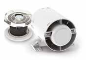
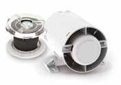
For short duct runs and shower applications. Loft mounted.
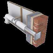
For long duct runs. Wall/window mounted options.
Wide range of multipurpose wall, window, ceiling and roof extract fans with optional integrated and remote controls.


Since our inception, Domus Ventilation has aimed to be the number one supplier of ventilation products in the UK market place.
We are constantly innovating and improving to reaffirm our position as market leader. We have an active portfolio of new and improved product introductions. The most recent of these introductions is the new HRXE-ZEUS from our MVHR range. These new additions complement our existing award winning product ranges NOX-FILT, the CMX- Multi plus our highly innovative Green Line Bend.
Product and service quality is of vital importance to us and we strive to deliver higher than expected levels based on customer feedback and new trends in the sector. If you have any questions or comments please get in touch with us on 03443 715 523.
SEPT
2018
Domus Ventilation is a manufacturer of market-leading ventilation systems that save energy and improve indoor air quality.
Formerly Polypipe Ventilation, the company has been reborn as Domus Ventilation, with new management and customer service teams, an expanded sales network and state-of-the-art production facilities in South Wales.
Domus Ventilation will continue to offer the multi award-winning Domus Ducting, that has been a UK market leader for over 50 years, as well as energy-efficient ventilation and indoor air quality systems.
Under the new name, and with an enhanced customer service team and increased sales force, Domus Ventilation is primed for growth and aims to be the number one supplier of ventilation products and accessories.
As a leading manufacturer of energy-saving ventilation systems, we offer high quality solutions for domestic and light commercial applications.
Understanding your ventilation requirements is integral to ensuring that we tailor our solutions to meet your needs.

Having established technical requirements, you will be supported each step of the way from order placement through to time planning.

Two significant manufacturing facilities, that help guarantee quick availability through a loyal nationwide network of Merchant and Electrical Wholesaler stockists.
Our national network of stockists offer a dedicated and managed logistics fleet, who are dedicated to providing efficient, quick and reliable delivery.

We believe at Domus Ventilation we have the best people within the industry, working together to support all our customers providing you with expert advice and guidance.
From project concept through to completion, Domus Ventilation can guide you through the whole process
The following is offered as Best Practice guidance only, with information taken from statutory bodies including ‘Approved Document F – Ventilation’ (2021 edition incorporating 2010 and 2013 amendments).
All Domus Ventilation products comply with the latest regulatory governance, with supporting literature such as Installation & Maintenance manuals.
External vents should be separated by a minimum of 300mm horizontally, if placed on the same façade.

Minimum distance as specified in building regulations
Duct clips or support banding should be positioned at equal distances and no more than 750mm apart. Ducting should not be positioned in direct contact with other surfaces, such as plasterboard ceilings, to prevent noise transfer into the dwelling.
This has been brought in owing to legislation changes, Part B fire regulations have recently changed and now confirm that no combustible material i.e. pvc is to be installed in a cavity within or on external surface of an external wall above 11m in Scotland and above 18m in England and Wales, therefore, giving us no option but to design and manufacture a metal version.
We recommend that all ducts be connected and sealed using a non-hardening sealant to minimise air leakage. Consideration should be made to ducts installed in non-accessible areas, such as a ceiling void, to have a permanent fixing in place to supplement the sealing, preventing dislodging or movement during or after installation. The use of duct tape is permitted but should not be used as the only method of providing an airtight seal.
All ducting should be sized in accordance with current building regulations. When using MEV and MVHR systems, the ducting selected should be suitable for use with the product types.
Domus Ventilation recommends that a minimum duct size of 204x60mm or 125mm be used with MEV and MVHR systems, to maintain an even distribution of airflow and low duct velocity. Please see pages 39-71 for all pressure drop calculations on our rigid ducting systems.
Domus semi-rigid radial ducting systems may also be used, contact Domus Ventilation for further information.
 Use fastening strap to support duct
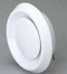
Installation and positioning of air valves and external grilles: The air valve shall be located on the opposite side of the room from internal opening doors, creating a cross flow of air
Should not be located less than 200mm to walls when installed on a ceiling

Should not be located less than 400mm from a ceiling when installed on a wall
Kitchen extract grilles should be a minimum of 600mm away from the hob
Air Valves should be lockable to prevent tampering once the system has been installed and commissioned.
All grille locations should take into consideration room layouts and be positioned in such a way as to minimise down draughts over seating and sleeping areas.
Note:
a. If the dwelling only has one habitable room, a minimum ventilation rate of 13l/s should be used.

b. For each additional bedroom, add 6l/s to the values shown in table above.

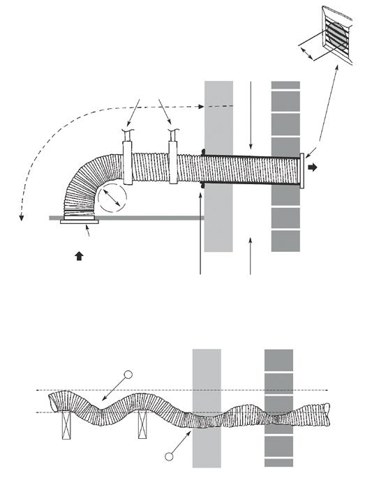
For flexible duct connected to axial fans the length is limited to 1.5 metres; for centrifugal fans the length limit is 6 metres (for extract rates 6 to 30l/s) and 3 metres (for extract rates 31-60l/s).
The number of bends is limited to two for up to 30l/s, and reduces to one bend for higher extract rates.
Flexible duct should be pulled taut to ensure that the full internal diameter is obtained and flow resistance minimised.
This is considered to have been achieved if the duct is extended to 90% of its maximum length.
Flexible ducting generally requires more support than rigid ducting. It is suggested that flexible ducts should be supported at intervals not exceeding 600mm.
Flexible duct should be:
Not more than 300mm in length
Located adjacent to fan units or air valves
Not used to form bends
To prevent cross-contamination, supply ductwork terminals should normally be separated from exhaust ductwork terminals and other potential sources of pollution by a minimum of 1m measured on plan. Increased separation distances may be required between the supply and any:
Soil and vent pipe terminal
Boiler flue outlet
Biomass or solid fuel chimney terminal
Proprietary fire components should be suitably tested and specified to take account of the test conditions. Appropriate standards include:
BS 476 Fire tests on building materials and structures (relevant parts)
BS EN 1365-2 Fire resistance tests for loadbearing elements. Floors and roofs
BS EN 1366-3 Fire resistance tests for service installations. Penetration seals
Air valves and terminals should be specified to be suitable for their location and function, and the velocity of the system. Airflow resistance should be calculated in accordance with BS EN 13141-2 Ventilation for buildings. Performance testing of components/ products for residential ventilation. Exhaust and supply air terminal devices.
Adjustable air valves should be lockable, to prevent building users from altering them.
Terminals should be designed to prevent the entry of birds and animals.
Condensate can form where duct passes through spaces outside of the insulated parts of the home (such as a roof void) or when ductwork carrying cold air passes through spaces within the insulated parts of the home. Ductwork should be insulated to reduce the risk of condensation formation.
Where insulation is required to prevent condensation formation, it should be continuous and vapour resistant. This can be achieved by using either suitable pre-insulated ductwork or a proprietary insulation system with a thermal resistance equivalent to a minimum of 25mm of insulating material, with a thermal conductivity of 0.04W/(m.k). Type
Ductwork located inside the insulated part of the home
located outside of the insulated part of the home
Intake Yes Yes
Exhaust Yes Yes
Service (supply and extract)
No Yes
Pre-insulated to achieve a thermal performance equivalent to at least 25mm of insulating material with a thermal conductivity of 0.04W/(m.K)
Loft insulation used to achieve a total thermal performance equivalent to at least 150mm of insulating material with a thermal conductivity of 0.04W/(m.K)
Whilst there are currently no regulations concerning the quality of air inside a property, the subject of IAQ has been well publicised over the last few years owing to rising health concerns.
Statistics such as Contaminants in the indoor environment are more than 1,000 times more likely to be inhaled than outdoor air (Levin, 2007) and can be up to 10 times more polluted than outside air (US EPA, 2001) and have worked well to shock the construction industry in to adopting continuous Mechanical Ventilation such as MVHR and MEV as standard.
37 of 43 UK REGIONS exceed the legal limits for
MEV and MVHR systems are increasingly being installed into new properties.
As a cost-effective means of lowering Dwelling Emission Rates to gain points towards achieving a higher SAP rating (as listed in the Product Characteristics Database), many developers and specifiers are seeing the benefit of adopting a whole house ventilation system, whilst also being able to improve the indoor environment for their clients.
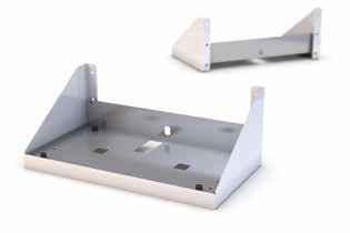
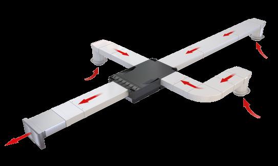
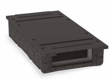
The HRXE-AV Anti-Vibration tray is suitable for all models within the range and can be used in both floor and wall installation
It is perfect for application where transfer of sound is a concern
When specifying or installing a ventilation system, consideration must be given to the total floor area, national Building Regulations, air permeability, occupancy levels, installation standards and ease of user operation and maintenance.
Select the most optimum system for your property and ensure your appliance’s performance is maximised by installing the most suitable Domus duct system.
HIGHLY EFFICIENT
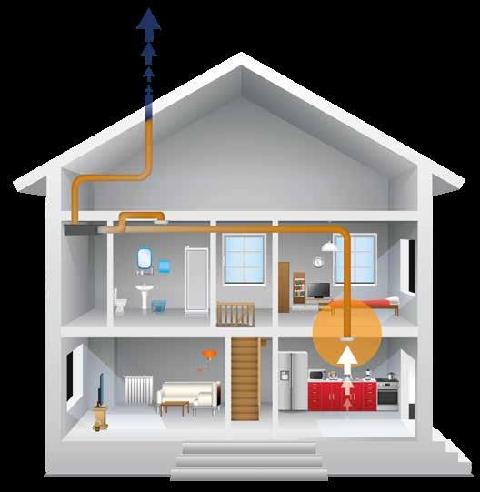
Helps to create a healthy and clean indoor air environment whilst reducing household energy consumption.
Also referred to as System 4 in Approved Document F of the Building Regulations, MVHR efficiently combines supply and extract ventilation into one centralised system.
As its primary function, waste, polluted and moist air is extracted from a dwelling’s wet room via a duct system and is passed through a heat exchanger before being exhausted outside. Fresh incoming air is filtered and as an added benefit, prewarmed via the heat exchanger and evenly distributed to the habitable rooms, thus reducing household energy consumption and the demand on existing heating systems.
The technology is most effective when installed in an air-tight dwelling as the effect is not compromised by external leakage.
A continuous, effective and efficient means of maintaining the indoor air quality that you breathe and live in.
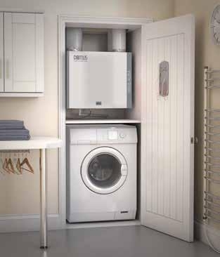
Also referred to as System 3 in Approved Document F of the Building Regulations, an MEV system consists of a centralised ventilation unit that continuously extracts waste, polluted and moist air from wet rooms and can be discreetly positioned in either a cupboard, utility room, ceiling or loft space.
An MEV system can be ducted throughout the dwelling and operated by the homeowner through a range of control options. Typically dual speed, MEV systems provide both low speed continuous trickle ventilation and high speed boost flow when required. Replacement fresh air is drawn into the dwelling through background ventilators i.e. air inlets, located in the living areas.
The highly efficient dMEV range offers continuous low level ventilation – to a single wet room, coupled with virtually silent operation.
Also known as System 3 in Approved Document F of the Building Regulations, decentralised Mechanical Extract Ventilation (dMEV) systems incorporate continuously running extract fans, designed to remove waste and moist air from a single wet room.
dMEV fans continuously extract the waste air at both low trickle or boost speeds, as determined by the homeowner through a range of control options. Replacement fresh air is then drawn into the dwelling via background ventilators located in the habitable rooms.
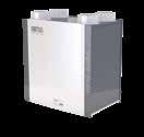
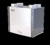
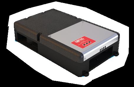
All HRXE-HERA models have been designed with 100% automatic bypass, as listed on the SAP Product Characteristics Database (PCDB).
The HRXE-HERA range operate by continuously extracting moistureladen air from ‘wet’ rooms within the property whilst simultaneously drawing in fresh, filtered supply air from outside.
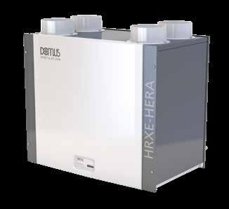
The heat from the extracted stale air is recovered via a heat exchanger inside the heat recovery unit which becomes tempered and filtered, before supplied in to the habitable rooms, creating comfortable and well ventilated homes.
The heat exchanger block within these units can recover up to 95% of the normally wasted heat. The two independent fans have full-speed control for background and boost ventilation rates
All The HRXE-HERA models have a Summer bypass function. In warmer months this function automatically activates to ensure the property is being well-ventilated and comfort levels are maintained in the home by continuously drawing in fresh filtered air into the habitable rooms
Owing to its intelligent design, there will be no reduction in airflow when operating in bypass mode, resulting in enhanced performance
Designed to provide optimised balanced (supply and extract) mechanical ventilation with heat recovery and both listed on the PCDB
Weight: 20kg
Code Description
HRXE-HERA-AV Anti-Vibration tray suitable for all HRXE-HERA models
297
Condensate Drain Kit for all HRXE-HERA models
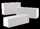
SPR428 Replacement filters (pair)
Codes Description
HRXE-HERA Standard unit with 100% bypass
HRXEHERA-H Standard unit with 100% bypass and integral humidistat
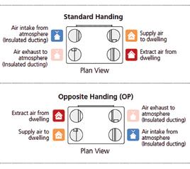
HRXE-HERAOP Opposite handed unit with 100% bypass
HRXE-HERAOPH Opposite handed unit with 100% bypass and integral humidistat
The maximum power consumption shown above (Watts) is consumed on units running continuously, not taking into account any heat recovery saving and based on SAP Product Characteristic Database (PCDB) testing. The breakout case-radiated dBA values are given for Hemispherical free field radiation at 3m - to obtain the Spherical radiated data, subtract 3 dBA.
Please note: Sound data is provided at a particular duty point for 25%, 50%, 75% and 100%. For accurate sound data at a specific speed duty, please call the office on 03443 715 523.
The unit is fully insulated, providing excellent thermal and acoustic characteristics and is complete with a multiplate, counter-flow, high-efficiency heat exchanger block, with a thermal efficiency of up to 95%. The heat exchanger is protected by G3 grade filters on fresh air inlet and system extract. The heat exchanger and filters are accessible via the front access panel, enabling quick and easy maintenance.
The unit has low energy, high-efficiency EC fan/motor assemblies with sealed for life bearings, the impellers are backward curved centrifugal type. The motors are suitable for an ambient temperature of 40ºC.
The unit is supplied complete with an insulated condensate drip tray and 21.5mm drain connection.
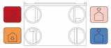
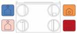
The unit is suitable for 125mm circular ducting. Note: The unit is also available in opposite handed format, refer to spigot configuration for set up.
The breakout noise level and power requirements as detailed by the unit manufacturer and in accordance with the ventilation equipment schedule.
Units shall be HRXE as manufactured by Domus Ventilation and shall be listed on the SAP PCDB.
HRXE-HERA-OP & HRXE-HERA-OPH are opposite handed assemblies compliant as per standard handed versions listed in SAP PCDB.
The supply and extract system shall be positioned as indicated on the drawings and in accordance with the particular fan schedule in the specification.
The combined supply and extract with heat recovery unit shall supply filtered fresh air to each of the habitable rooms and moisture-laden air will be extracted from all wet areas, e.g. bathroom, en suite, w.c., kitchen, utility rooms etc. The supply air will be pre-heated by the warm extract air via the integrated counter-flow heat exchanger element. The extracted air will also be filtered before it reaches the heat exchanger block.
The ventilation unit shall vary its speed and, therefore, the ventilation rate, as it receives signals from one of the following:
• Switched live signal from light/remote switches
• When signals are received, the fan shall alter its speed to adjustable, normal and boost rates
The unit has the facility to commission the supply and extract
fans independently on minimum speed (continuous background ventilation) and boost speed via inbuilt minimum and maximum speed adjustment. The fans have infinitely variable speed control.
The bypass damper opens automatically via a wax actuator, allowing the air to bypass the heat exchanger to deliver fresh filtered air during the warmer months.
The automatic bypass diverts 100% airflow around the heat exchanger with no reduction in airflow as independently tested by the BRE.
The integral humidity sensor incorporated within the extract fan chamber will automatically boost both the extract and supply fan to the commissioned boost speed, when the humidity level exceeds that set by the front panel mounted adjustment potentiometer.
All versions shall have the following functions integrally mounted within the fan unit on a purpose made PCB, all such components are pre-wired and factory fitted by the manufacturer:
Independent control of background supply and extract flow rates
Independent control of boost speed supply and extract flow rates
Integral heat exchanger frost protection
Fan failure indication
Integral S/L terminal for boost from remote switch, e.g. light switch
Additional S/L terminal for 100% boost speed from remote switch, e.g. plate switch

Discreet daily run monitor
Indication and controls – the unit shall have clear LED visual indication for maintenance, servicing and operation mode, i.e. HX bypass, frost protection
The unit comes with a 5 year warranty which starts from the day of delivery, and includes parts and labour for the first year and parts only for the remaining four years
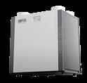
All HRXE-AURA models have been designed with 100% automatic bypass, as listed on the SAP Product Characteristics Database (PCDB).
The HRXE range operate by continuously extracting moisture-laden air from ‘wet’ rooms within the property whilst simultaneously drawing in fresh, filtered supply air from outside.
The heat from the extracted stale air is recovered via a heat exchanger inside the heat recovery unit which becomes tempered and filtered, before supplied in to the habitable rooms, creating comfortable and well ventilated homes.

The heat exchanger block within these units can recover up to 95% of the normally wasted heat. The two independent fans have full-speed control for background and boost ventilation rates
All The HRXE-AURA range has a Summer bypass function. In warmer months this function automatically activates to ensure the property is being well-ventilated and comfort levels are maintained in the home by continuously drawing in fresh filtered air into the habitable rooms
Owing to its intelligent design, there will be no reduction in airflow when operating in bypass mode, resulting in enhanced performance
Designed to provide optimised balanced (supply and extract) mechanical ventilation with heat recovery and both listed on the PCDB
Weight: 24kg
Code Description
HRXE-AURA-AV Anti-Vibration tray suitable for all HRXE-AURA models
297 Condensate Drain Kit for all HRXE-AURA models
SPR428 Replacement filters (pair)
Codes Description
HRXE-AURA Standard unit with 100% bypass
HRXEAURA-H Standard unit with 100% bypass and integral humidistat
HRXE-AURAOP Opposite handed unit with 100% bypass
HRXE-AURAOPH Opposite handed unit with 100% bypass and integral humidistat
The maximum power consumption shown above (Watts) is consumed on units running continuously, not taking into account any heat recovery saving and based on SAP Product Characteristic Database (PCDB) testing. The breakout case-radiated dBA values are given for Hemispherical free field radiation at 3m - to obtain the Spherical radiated data, subtract 3 dBA.
Please note: Sound data is provided at a particular duty point for 25%, 50%, 75% and 100%. For accurate sound data at a specific speed duty, please call the office on 03443 715 523.

The unit is fully insulated providing excellent thermal and acoustic characteristics and is complete with a multiplate, counter-flow, high-efficiency heat exchanger block, with a thermal efficiency of up to 95%. The heat exchanger is protected by G3 grade filters on fresh air inlet and system extract. The heat exchanger and filters shall be accessible via the front access panel, enabling quick and easy maintenance.
The unit has low energy, high-efficiency EC fan/motor assemblies with sealed-for-life bearings, the impellers are backward curved centrifugal type. The motors are suitable for an ambient temperature of 40ºC.
The unit is supplied complete with an insulated condensate drip tray and 21.5mm drain connection.
The unit is suitable for 150mm circular ducting. Note: The unit is also available in opposite handed format, refer to spigot configuration for set up.
The breakout noise level and power requirements are as detailed by the unit manufacturer and in accordance with the ventilation equipment schedule.
Units shall be HRXE as manufactured by Domus Ventilation and shall be listed on the SAP PCDB.
HRXE-AURA-OP & HRXE-AURA-OPH are opposite handed assemblies compliant as per standard handed versions listed in SAP PCDB.
The supply and extract system is positioned as indicated on the drawings and are in accordance with the particular fan schedule in the specification.
The combined supply and extract with heat recovery unit supplies filtered fresh air to each of the habitable rooms and moisture-laden air is extracted from all wet areas, e.g. bathroom, en suite, w.c, kitchen, utility rooms etc. The supply air will be pre-heated by the warm extract air via the integrated counter-flow heat exchanger element. The extracted air is also filtered before it reaches the heat exchanger block.
The ventilation unit varies its speed and therefore the ventilation rate, as it receives signals from one of the following:
• Switched live signal from light/remote switches
• When signals are received, the fan shall alter its speed to adjustable, normal and boost rates
The unit has the facility to commission the supply and extract fans independently on minimum speed (continuous background ventilation) and boost speed via inbuilt minimum and maximum speed adjustment. The fans have infinitely variable speed control.
The bypass damper opens automatically via a wax actuator, allowing the air to bypass the heat exchanger to deliver fresh filtered air during the warmer months.
The automatic bypass diverts 100% airflow around the heat exchanger with no reduction in airflow as independently tested by the BRE.
Integral Humidity Sensor
The integral humidity sensor incorporated within the extract fan chamber will automatically boost both the extract and supply fan, to the commissioned boost speed, when the humidity level exceeds that set by the front panel mounted adjustment potentiometer.
All versions have the following functions integrally mounted within the fan unit on a purpose made PCB, all components are pre-wired and factory fitted by the manufacturer:
Independent control of background supply and extract flow rates
Independent control of boost speed supply and extract flow rates
Integral heat exchanger frost protection
Fan failure indication
Integral S/L terminal for boost from remote switch, e.g. light switch
Additional S/L terminal for 100% boost speed from remote switch, e.g. plate switch
Discreet daily run monitor
Indication and controls – the unit shall have clear LED visual indication for maintenance, servicing and operation mode, i.e. HX bypass, frost protection
The unit comes with a 5 year warranty which starts from the day of delivery, and includes parts and labour for the first year and parts only for the remaining four years
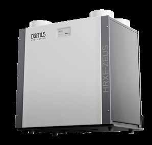
All HRXE-ZEUS models have been designed with 100% automatic bypass, listed on the SAP Product Characteristics Database (PCDB).
The HRXE-ZEUS range operate by continuously extracting moistureladen air from ‘wet’ rooms within the property whilst simultaneously drawing in fresh, filtered supply air from outside.
The heat from the extracted stale air is recovered via a heat exchanger inside the heat recovery unit which becomes tempered and filtered, before supplied into the habitable rooms, creating comfortable and well-ventilated homes.
The heat exchanger block within these units can recover up to 95% of the normally wasted heat. The two independent fans have full-speed control for background and boost ventilation rates.
The HRXE-ZEUS range has a summer bypass function. In warmer months this function automatically activates to ensure the property is being well-ventilated and comfort levels are maintained in the home by continuously drawing in fresh filtered air into the habitable rooms.
Due to its intelligent design, there will be no reduction in airflow when operating in bypass mode resulting in enhanced performance.
Designed to provide optimised balanced (supply and extract) mechanical ventilation with heat recovery and listed on the PCDB.
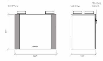
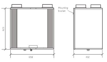
Weight: 45kg
Accessories
Codes Description
HRXEZEUS-AV Anti-Vibration tray suitable for all HRXE-ZEUS models
297 Condensation Drain Kit for all HRXE-ZEUS models
SPR459 Replacement filters (Pair)
Code Description
HRXE-ZEUS Standard unit with 100% bypass
HRXE-ZEUS-H Standard unit with 100% bypass and integral humidistat
HRXE-ZEUS-OP Opposite handed unit with 100% bypass
HRXE-ZEUS-OPH Opposite handed unit with 100% bypass and integral humidistat
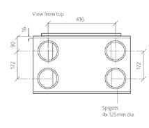
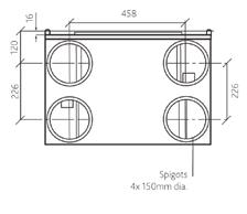
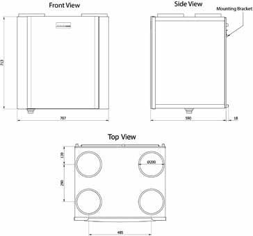
Dimensions (mm)
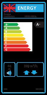
The maximum power consumption shown above (Watts) is consumed on units running continuously, not taking into account any heat recovery saving and based on SAP Product Characteristic Database (PCDB) testing. The breakout case-radiated dBA values are given for Hemispherical free field radiation at 3m - to obtain the Spherical radiated data, subtract 3 dBA.
Please note: Sound data is provided at a particular duty point for 25%, 50%, 75% and 100%. For accurate sound data at a specific speed duty, please call the office on 03443 715 523.
The unit is fully insulated, providing excellent thermal and acoustic characteristics and is complete with a multiplate, counter-flow, high-efficiency heat exchanger block, with a thermal efficiency of up to 95%. The heat exchanger is protected by G3 grade filters on fresh air inlet and system extract. The heat exchanger and filters are accessible via the front access panel, enabling quick and easy maintenance.
The unit has low energy, high-efficiency EC fan/motor assemblies with sealed for life bearings, the impellers are backward curved centrifugal type. The motors are suitable for an ambient temperature of 40ºC.
The unit is supplied complete with an insulated condensate drip tray and 32mm drain connection.
The unit is suitable for 125mm circular ducting. Note: The unit is also available in opposite handed format, refer to spigot configuration for set up.
The breakout noise level and power requirements as detailed by the unit manufacturer and in accordance with the ventilation equipment schedule.
Units shall be HRXE as manufactured by Domus Ventilation and shall be listed on the SAP PCDB.
HRXE-ZEUS-OP & HRXE-ZEUS-OPH are opposite handed assemblies compliant as per standard handed versions listed in SAP PCDB.
The supply and extract system shall be positioned as indicated on the drawings and in accordance with the particular fan schedule in the specification.
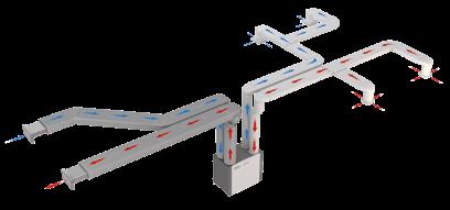
The combined supply and extract with heat recovery unit shall supply filtered fresh air to each of the habitable rooms and moisture-laden air will be extracted from all wet areas, e.g. bathroom, en suite, w.c., kitchen, utility rooms etc. The supply air will be pre-heated by the warm extract air via the integrated counter-flow heat exchanger element. The extracted air will also be filtered before it reaches the heat exchanger block.
The ventilation unit shall vary its speed and, therefore, the ventilation rate, as it receives signals from one of the following:
• Switched live signal from light/remote switches
• When signals are received, the fan shall alter its speed to adjustable, normal and boost rates
The unit has the facility to commission the supply and extract
fans independently on minimum speed (continuous background ventilation) and boost speed via inbuilt minimum and maximum speed adjustment. The fans have infinitely variable speed control.
The bypass damper opens automatically via a wax actuator, allowing the air to bypass the heat exchanger to deliver fresh filtered air during the warmer months.
The automatic bypass diverts 100% airflow around the heat exchanger with no reduction in airflow as independently tested by the BRE.
The integral humidity sensor incorporated within the extract fan chamber will automatically boost both the extract and supply fan to the commissioned boost speed, when the humidity level exceeds that set by the front panel mounted adjustment potentiometer.
All versions shall have the following functions integrally mounted within the fan unit on a purpose made PCB, all such components are pre-wired and factory fitted by the manufacturer:
Independent control of background supply and extract flow rates
Independent control of boost speed supply and extract flow rates
Integral heat exchanger frost protection
Fan failure indication
Integral S/L terminal for boost from remote switch, e.g. light switch
Additional S/L terminal for 100% boost speed from remote switch, e.g. plate switch
Discreet daily run monitor
Indication and controls – the unit shall have clear LED visual indication for maintenance, servicing and operation mode, i.e. HX bypass, frost protection
The unit comes with a 5 year warranty which starts from the day of delivery, and includes parts and labour for the first year and parts only for the remaining four years

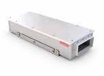
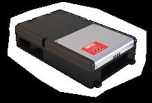
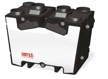
Ideal for larger developments, the HRX2D is a powerful yet highly efficient MVHR unit. Operation is automated with an integral humidistat to boost performance if necessary. The HRX2D comes complete with Domus Ventilation’s unique Bluebrain® Controller which is used to commission the system, but also allows home-owner management of system operation with settings such as Holiday Mode and a warning for filter replacement.
Extremely low Specific Fan Power (SFP) down to 0.57 (W/l/s)
Bluebrain control optimises the unit’s functionality and allows for quick and easy commissioning through simple speed adjustment buttons
High heat exchange efficiency up to 94%
Very quiet in operation, down to 35dB(A)
Effectively extracts up to 113l/s at 150 Pa
Code Description
HRX2D Domus HRXD Mechanical Ventilation with Heat Recovery Unit
The unit is fully insulated, providing excellent thermal and acoustic characteristics and is complete with a multi-plate, counter-flow, highefficiency heat exchanger block; with a thermal efficiency of up to 94%. The heat exchanger is protected by G3 grade filters at fresh air inlet and system extract.
The heat exchanger filters are accessible via the front access panel, enabling quick and easy maintenance.
The unit has low energy, high-efficiency EC fan/motor assemblies with sealed-for-life bearings; the impellers are backward-curved centrifugal type. The motors are suitable for an ambient temperature of 40°C. The unit is supplied complete with an insulated condensate drip tray and 21.5mm drain connection. The unit is suitable for 150mm circular ducting. The breakout noise level and power requirements are as detailed by the unit manufacturer and in accordance with the ventilation equipment schedule. Units shall be HRX2D as manufactured by Domus Ventilation and shall be listed on the SAP PCDB.
The supply and extract system is positioned as indicated on the drawings and is in accordance with the fan schedule in the specification.
The combined supply and extract with heat recovery unit supplies filtered fresh air to each of the habitable rooms and moisture-laden air is extracted from all wet areas, e.g. bathroom, ensuite, kitchen, utility rooms etc. The supply air is pre-heated by the warm extract air via the integrated counter-flow heat exchanger element. The extracted air can also be filtered before it reaches the heat exchanger block. The ventilation unit varies its speed and, therefore, the ventilation rate, as it receives signals from one of the following: Switched live signal from light/remote switches via the Bluebrain Controller. When signals are received, the fan alters its speed to adjustable, normal and boost rates. The unit has the facility to commission the supply and extract fans independently on minimum speed (continuous background ventilation) and boost speed via inbuilt minimum and maximum speed adjustment. The fans have infinitely variable speed control.
The bypass damper opens automatically via a wax actuator, allowing the air to bypass the heat exchanger to deliver fresh filtered air
during the warmer months. The automatic bypass diverts 100% airflow around the heat exchanger with no reduction in airflow, as independently tested by the BRE.
The integral humidity sensor incorporated within the extract fan chamber will automatically boost both the extract and supply fan, to the commissioned boost speed, when the humidity level exceeds that set by the Bluebrain Controller.
The HRX2D has the following functions integrally mounted within the separate fan wiring centre and controlled by the Bluebrain control panel, which are:
Independent control of background supply and extract flow rates
Independent control of boost speed supply and extract flow rates
Integral heat exchanger frost protection
Fan failure indication
Integral S/L terminal for boost from remote switch, e.g. light switch
Additional S/L terminal for 100% boost speed from remote switch, e.g. plate switch
Discreet daily run monitor
Indication and controls – The unit has a clear LCD visual indication for maintenance, servicing and operation mode, i.e. HX bypass, frost protection
The controller comes complete with commissioning and end user functions. The display will be a 2.75˝ LCD display and will remain on standby until the control button is engaged.
The initial display will show the MVHR system status as listed below:
Current fan speed
Current indoor/outside temperature
Indicate when the Summer bypass is activated
Indicate when frost protection is activated
Indicate when the filters require cleaning/changing
The unit comes with a 2 year warranty (parts only) which starts from the day of delivery.
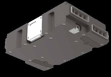
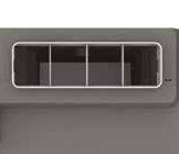
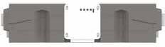
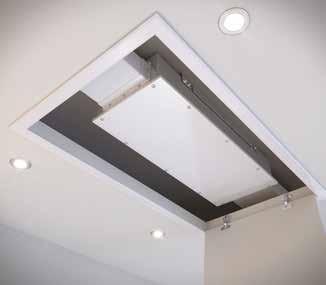
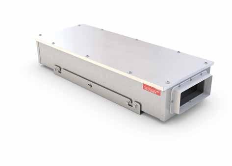
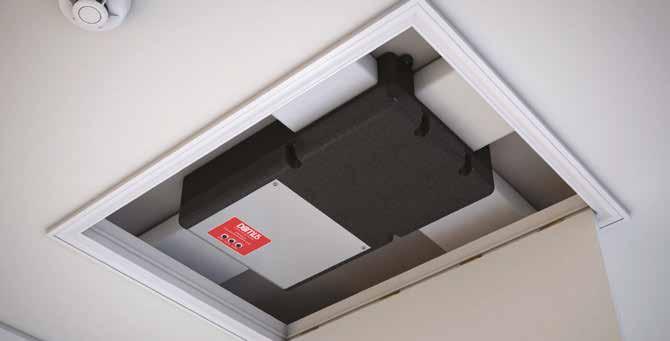
Waste, moist air is extracted from wet rooms (bathroom, en-suite and kitchen etc)The most compact and intelligent MVHR ceiling unit on the market. HRX-aQ models enable contractors to deliver quick installation of a unique ventilation system; complete with Bluebrain Controller.
Specific Fan Power (SFP) down to 0.72(W/l/s)
Bluebrain control optimises the unit’s functionality and allows for quick and easy commissioning through simple speed adjustment buttons
High heat exchange efficiency up to 87%
Extremely quiet in operation, 24dB(A)
Compact and lightweight – weighs 7.9kg and measures 199mm in depth
Effectively extract up to 30l/s at boost (for a kitchen and two wet rooms)
Weight: 7.9kg
Installation
Building Regulations Compliant
ErP Directive Compliant
Accessories
Codes Description
Ideal for restrictive applications such as ceiling voids or tight spaces
297 Condensate Drain (not included)
AQHC-CC8 8 metre data cable (not included)
SPR442 Replacement filters for AQH200-B & AQH200-S units (pair)
Ultimate, flexible and intelligent control
Straightforward, accurate commissioning
See Page 21
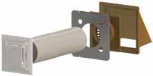
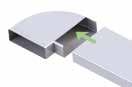
Offset duct makes fitting simple
204x60mm socket connections enable the unit to directly fit onto rigid ducting and remove the need for additional adapters. For information on Domus rigid ducting, go to page 48. For Radial semi-rigid ducting, go to page 125.
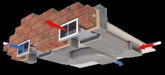
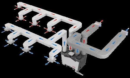
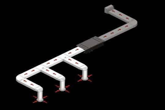
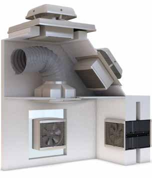
 System illustration
Fresh incoming air is drawn in
Waste air is exhausted to the outside
Domus HRX-aQ MVHR ceiling unit with Bluebrain control
Domus condensate drain Domus rigid ducting Domus air valve (room terminal) with plenum
Clean filtered air is supplied into the
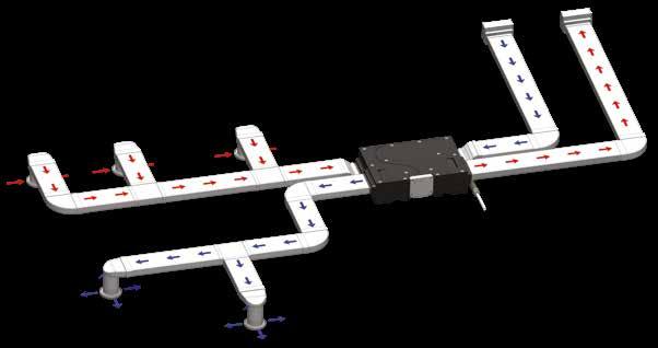
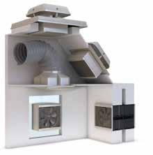
System illustration
Fresh incoming air is drawn in
Waste air is exhausted to the outside
Domus HRX-aQ MVHR ceiling unit with Bluebrain control
Domus condensate drain Domus rigid ducting Domus air valve (room terminal) with plenum
Clean filtered air is supplied into the
The breakout case-radiated dBA values are given for Hemispherical free field radiation at 3m - to obtain the Spherical radiated data, subtract 3 dBA. *Noise not normally heard by the human ear.
The unit is fully insulated, providing excellent thermal and acoustic characteristics and is complete with a multi-plate, counter-flow, highefficiency heat exchanger block, with a thermal efficiency of up to 88%. The heat exchanger is protected by G3 grade filters at fresh air inlet and system extract.
The heat exchanger filters shall be accessible via the front access panel, enabling quick and easy maintenance.
The unit has low energy, high-efficiency EC fan/motor assemblies with sealed for life bearings, the impellers are backward-curved centrifugal type. The motors are suitable for an ambient temperature of 40˚C. The unit is supplied complete with a condensate drip tray and is suitable for 204mm x 60mm rectangular ducting. The breakout noise level and power requirements are detailed by the unit manufacturer and in accordance with the ventilation equipment schedule.
Units AQH200-S and AQH200-B are manufactured by Domus Ventilation and shall be listed on the SAP PCDB.
The supply and extract system will be positioned as indicated on the drawings and is in accordance with the fan schedule in the specification.
The combined supply and extract with heat recovery unit supplies filtered fresh air to each of the habitable rooms and moisture-laden air is extracted from all wet areas, e.g. bathroom, en suite, kitchen, utility rooms etc. The supply air will be pre-heated by the warm extract air via the integrated counter-flow heat exchanger element. The extracted air will also be filtered before it reaches the heat exchanger block. The ventilation unit varies its speed and, therefore, the ventilation rate, as it receives signals from one of the following: Switched live signal from light/remote switches via the Bluebrain Controller. When signals are received, the fan will alter its speed to adjustable, normal and boost rates. The unit has the facility to commission the supply and extract fans independently on minimum speed (continuous background ventilation) and boost speed via inbuilt minimum and maximum speed adjustment. The fans have infinitely variable speed control.
The bypass damper opens automatically via a wax actuator, allowing the air to bypass the heat exchanger to deliver fresh filtered air during the warmer months. The automatic bypass diverts 100% airflow around the heat exchanger with no reduction in airflow, as independently tested by the BRE.
The integral humidity sensor incorporated within the extract fan chamber will automatically boost both the extract and supply fan, to the commissioned boost speed, when the humidity level exceeds that set by the Bluebrain Controller.
The AQH200-S and AQH200-B shall have the following functions integrally mounted within the separate fan wiring centre and controlled by the Bluebrain control panel, which is:
Independent control of background supply and extract flow rates
Independent control of boost speed supply and extract flow rates
Integral heat exchanger frost protection
Fan failure indication
Integral S/L terminal for boost from remote switch, e.g. light switch
Additional S/L terminal for 100% boost speed from remote switch, e.g. plate switch
Discreet daily run monitor
Indication and controls – The unit shall have clear LCD visual indication for maintenance, servicing and operation mode, i.e. HX bypass, frost protection
The controller comes complete with commissioning and end user functions. The display will be a 2.75˝ LCD display and will remain on standby until such time a control button is engaged.
The initial display will show the MVHR system status as listed below:
Current fan speed
Current indoor/outside temperature
Indicate when the Summer bypass is activated
Indicate when frost protection is activated
Indicate when the filters require cleaning/changing
The unit comes with a 2 year warranty which starts from the day of delivery.
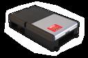
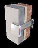
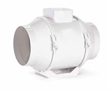
The NOX-FILT range is Domus Ventilation’s answer to the increasing demand for improved indoor air quality in the construction industry.
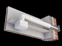
This range of in-line carbon filters are designed to be situated on the supply leg of a mechanical ventilation system and preventing up to 99.5% of airborne contaminants entering the property. Whilst the immediate emphasis is on the filtration of harmful NO2, often found in high levels within cities across the UK, there is also the option of a PM2.5 pre-filter to maximise the filtration of Particulate Matter equal or larger in size to 2.5 microns.
There are two units available in the range with the only difference being what filters are included at purchase. The NOX-FILT houses a carbon filter cell only, whereas the NOXFILT2.5 includes a PM2.5 pre-filter.
To specify the NOX-FILT with or without a PM2.5 pre-filter, choose the relevant code from the table opposite.
Up to 99.5% NO2 filtration
Simple to replace, single carbon filter cartridge
Low resistance
Optional PM2.5 pre-filter offering increased Particulate Matter filtration
Low profile for space restrictions
Tested in accordance with BS EN ISO 7235:2009
Removes up to 99.5% of harmful NO2
The NOX-FILT is manufactured in sheet metal, with an integral foam lining to reduce noise and provide internal sealing. Each in-line filter has the ability to have an optional PM10 or PM2.5 pre-filter inserted into the filter box to be capable of additional particulate filtration; particularly from diesel vehicle fumes.
The NOX-FILT comes complete with a removable mounting bracket. The NOX-FILT comes complete with a plastic construction carbon filter, containing two 30mm (approx.) beds of activated carbon pellets providing a large surface to filter the airflow. The filters can easily be removed and replaced when required. The filters have a minimum efficiency of between 96% and 99.5% effectiveness in the removal of Nitrogen Dioxide.
The unit efficiency will be confirmed and independently verified by a BRE (Building Research Establishment) test method and the information will be provided by the filter manufacturer for approval.
The unit is suitable for 220x90mm ducting.
The unit will be installed in conjunction with the manufacturer’s installation and maintenance guidelines.
10 - 95
Temperature range 0C -20 - +51
The unit comes with a 5 year warranty; 1 year parts and labour, remaining years parts only. This warranty is void if the equipment is modified without authorisation, is incorrectly applied, misused, disassembled or not installed, commissioned and maintained in accordance with the details contained in the I&M manual and general good practice.
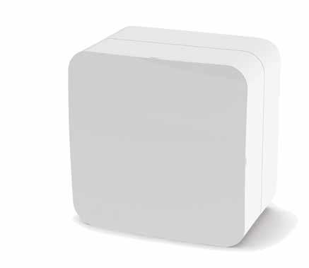
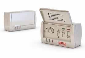
The Domus Ventilation range of control options are ideal for mechanical extract appliances designed for remote switch operation.
More sensitive than traditional humidistat controls, Intelligent Humidity Control (IHC) identifies a significant change in humidity.
Timer adjustable between 2-25 minutes.
W89mm x H89mm x D54mm* 5 amps
Code ANC802A
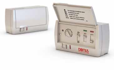
More sensitive than traditional humidistat controls, Intelligent Humidity Control (IHC) identifies a significant change in humidity. Neon indicator and pull cord override.
W89mm x H89mm x D54mm* 5 amps
Code ANC808A
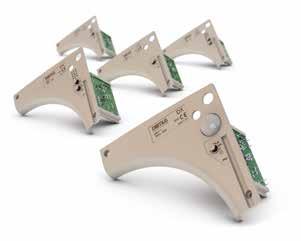
All products can be flush or surface mounted using a standard single pattress box.
Activates by detecting movement. Detection distance of up to five metres. Timer adjustable between 2-25 minutes. W89mm x H89mm x D54mm* 5 amps
Code ANC813A
Adjustable time delay between 2-25 minutes after the light switch has been turned off.
W89mm x H89mm x D54mm* 5 amps
Code ANC108A
Branded switch that provides two speed options.
W87mm x H87mm x D30mm
Code ANC848A
Branded switch that provides three speed options
W87mm x H87mm x D30mm
Code ANC850A

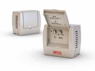
More sensitive than traditional humidistat controls, Intelligent Humidity Control (IHC) identifies a significant change in humidity. Timer adjustable between 2-25 minutes.

W89mm x H89mm x D54mm* 5 amps
Code ANC846A

Provides two speed operation for twin speed fans.
W89mm x H89mm x D54mm* 5 amps
Code ANC812A
Optimises Domus MVHR systems, as well as making commissioning simpler

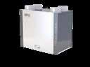
The CMX-MULTI showcases the BEST SFP on the market whilst maintaining a unique 125mm depth for simple, flexible installation.
Aimed at the Residential market, its shape and size conform with New-Build restrictions, whilst also making it ideal for retro-fit projects owing to direct duct runs and wall or ceiling void fixings. Quiet running, whilst comfortably providing impressive airflow rates and with a choice of models with and without integral humidistat, the CMX-MULTI range provide the solution in Mechanical Extract Ventilation.
SFP down to 0.14 (W/l/s) at K+1
CMX-MULTI-H has integral humidistat, ideal for specification works
3 inlet spigots for simplified multi-room extraction
204x60mm spigots allowing direct duct runs from the unit, saving time and money on site
Dimensions (mm)
Supports kitchen and up to six wet rooms
Building Regulations Compliant
ErP Directive Compliant
Must be fitted:
Direct to a ceiling or in a loft space
Within a joist space
One of the BEST SFP on the Market!
One of the slimmest and lightest MEV on the UK market!
The unit has been designed specifically for incorporation within a system designed to comply with the requirements of Part F Building Regulations. Ducting and grilles forming part of the system are specified elsewhere. Units CMX-MULTI are manufactured by Domus Ventilation and are listed on the SAP PCDB.
This unit is manufactured by a BSI Registered Firm with ISO 9000 certification. The unit’s casing is made of ABS, moulded plastic and EPP moulded foam.
The unit incorporates mounting hole points located at each corner for mounting to a rigid surface. When installed, the unit should not project any more than 125mm from the surface onto which it installed. Air discharge from the unit will be via a tapered rectangular spigot for easy connection to ducting.
The unit is capable of a three-inlet format. The unit casing has the facility to allow the connection, via tapered air inlet spigots supplied with three 204mm x 60mm spigots.
The unit is constructed with one removable panel allowing full maintenance access, but it is not required to be removed for installation as the unit is supplied with a flying lead. The unit incorporates a fully speed adjustable (note: stepped speed control will not be acceptable) low energy, high efficiency DC fan/ motor assembly with sealed for life bearings designed to operate continuously at a pre-set ‘background’ design airflow rate, with the ability to increase to a pre-set ‘boost’ or a pre-set ‘purge’ design airflow rate as and when required. It operates up to an ambient temperature of 40°C and fitted with a locked rotor protection device.
The impeller should be a centrifugal backward curved type, dynamically balanced and mounted directly onto the motor. The unit incorporates electrical connections to allow for the units ‘boost’ airflow to be triggered by a switched live signal, 230V. The CMX-MULTI-H has an integral humidity sensor which operates the ‘boost’ function. Both the CMX-MULTI & CMX-MULTI-H is offered with a 2 year warranty; 1 year parts and labour, remaining year parts only.
With an impressive airflow performance of up to 120l/s, the CMX-S is suitable for both Residential and Light Commercial applications. At just 125mm in depth, the CMX-S is one of the most versatile, easy to install and energy efficient MEV solutions available on the market.
High air flow performance up to 120l/s
In-line ports enable straightforward duct connection
Flexible home owner control (3 speed options)
Installation
Building Regulations Compliant
ErP Directive Compliant
Floor area up to 275m²
Must be fitted:
- Direct to a ceiling or in a loft space
- Within a joist space
Domus CMX air supply kits provide effective background ventilation
System illustration
Code Accessories
ANC108A Timer Switch
ANC802A Timer and Humidity Switch
ANC808A Timer and Humidity Switch with Neon indicator and pull cord
ANC813A Timer and PIR Switch
ANC846A Timer and Humidity Switch with Duct Mounted Sensor
ANC848A Low/Boost Switch
ANC850A Low/Boost/Purge Switch
CMX-ASK1B Air Supply Kit with Brown Cowl
CMX-ASK1W Air Supply Kit with White Cowl
ELE150R Six Input Junction Box
SPR439 Commissioning Tool
For technical information visit: www.domusventilation.co.uk
The breakout case-radiated dBA values are given for Hemispherical free field radiation at 3m – to obtain the Spherical radiated data, subtract 3 dBA.
The unit has been designed specifically for incorporation within a system designed to comply with the requirements of Part F Building Regulations. Ducting and grilles forming part of the system are specified elsewhere. Unit CMX-S is manufactured by Domus Ventilation and is listed on the SAP PCDB.
The unit is manufactured by a BSI Registered Firm with ISO 9000 certification. The unit’s casing is made of ABS, moulded plastic and EPP moulded foam. The unit incorporates four mounting hole points for mounting to a rigid surface. When installed the unit should not project any more than 125mm from the surface onto which it is installed. Air discharge from the unit will be via a tapered rectangular spigot for easy connection to ducting. The unit is capable of a single inlet format. The unit casing has the facility to allow the connection, via tapered air inlet spigots supplied with one 220mm x 90mm spigot.
The unit is constructed with one removable panel allowing full maintenance access. The unit incorporates a fully speed adjustable (note: stepped speed control will not be acceptable) low energy, high efficiency EC fan/motor assembly with sealed for life bearings designed to operate continuously at a pre-set ‘background’ design airflow rate with the ability to increase to a pre-set ‘boost’ or a pre-set ‘purge’ design airflow rate as and when required. It operates up to an ambient temperature of 40°C and be fitted with a locked rotor protection device.
The impeller should be a centrifugal backward curved type, dynamically balanced and mounted directly onto the motor. The unit incorporates electrical connections to allow for the unit’s ‘boost’ airflow to be triggered by a switched live signal, 230V.
The CMX-S unit is offered with a 2 year warranty; 1 year parts and labour, remaining year parts only.
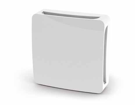
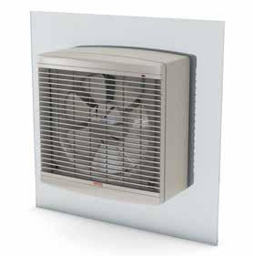
Our range of bathroom and kitchen fans provide rapid local extraction and include axial, in-line and centrifugal options. The Domus range has earned itself a superb reputation for quality, reliability and ease of installation.
Previously known as System 1 in Approved Document F of the Building Regulations, intermittent extract is a classic method of ventilating a home, either under occupant or automatic control i.e. a timer or a pull cord.
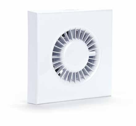
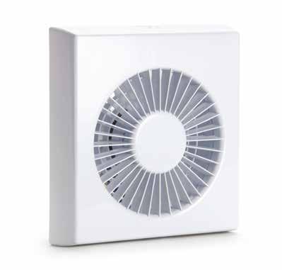
Our Sapphire range
Ultra quiet ventilation
Stylish design
Complies with Building Regulations and the ErP Directive
Optional fascias for axial 100mm fans
UK manufactured
Where is it safe to install a fan?
Fans are commonly 240 Volts, however, to protect occupants who need a fan installing close to a shower or bath, there are Separated Extra Low Voltage (SELV), 12 Volt, fans available.
Please use our illustration to help you know where you should and SHOULDN’T install a fan, as well as knowing where you need a 240 or 12 Volt fan.
For more information, see section 701 of British Standard 7671:2008.
Zone 0
No fans permitted.
Outside Zone Fans positioned in this area will be less effective.
Zone 1 12 Volt (SELV) fans. Must be positioned above Zone 0 over 2.25m from the floor.
Zone 2 230 Volt fans. Must be positioned horizontally 0.6m from Zone 1.
If in doubt, contact a qualified electrician for installation.
one
What sort of property are you installing into:
A new-build property? An existing property?
NEW-BUILD & REPLACING FANS REPLACING FANS
What sort of fan and model do you want:
What wet room are you installing into:
Connect to a short duct run, up to 1.5m in length, typically running through a wall to an external grille.
Perfect for shower applications and commonly mounted in a loft or ceiling void with up to 3m of duct.
Suitable for longer duct runs up to 6m in length and can be wall or ceiling mounted.
What voltage your fan should be: 240V or 12V (SELV).
For more information on whether you need a 240V or a 12V (SELV) fan, see page 41.
What extra options do you need:
SYSTEM 1 | INTERMITTENT EXTRACT | AXIAL FANS | SAPPHIRE RANGE


Extract rates comply with current Building Regulation requirements
Offers very low SFP down to 0.22 (W/l/s)
Provides effective ventilation
Quiet in operation
Stylish fascia to fit interior design scheme
Suitable for bathroom and toilet
Ability to mix and match fascia options
SYSTEM 1 | INTERMITTENT EXTRACT | AXIAL FANS | SAPPHIRE RANGE
100mm (4")
Mounts onto a wall
Key features
Provides effective ventilation
Quiet in operation
Stylish fascia to fit interior design scheme
Ability to mix and match fascia options, see page 31
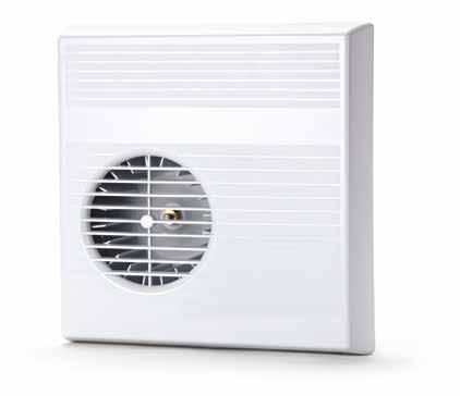
SYSTEM 1 | INTERMITTENT EXTRACT | AXIAL FANS | SDF RANGE 100mm (4")
Mounts onto a wall
Key features
Accessories
1K Wall Fitting Kit
ANC710A Chrome effect cover
SDF901WFK Window fitting kit for 100mm SDF and SVC fans

Performance

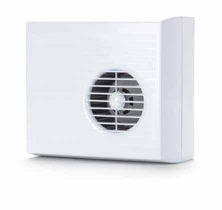
SYSTEM 1 | INTERMITTENT EXTRACT | AXIAL FANS | SVC RANGE
100mm (4") AUTO SHUTTER

Mounts onto a wall
Key features
Automatic shutters prevent backdraught from entering bathroom or toilet
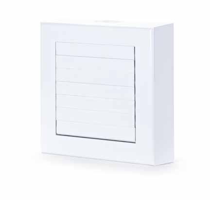
Quiet in operation
Shutters are operated mechanically on the pull cord version or via thermoactuator system on all other models
Complies with
SVC100B
SVC100TB
Accessories
1K Wall Fitting Kit
SDF901WFK Window fitting kit for 100mm SDF and SVC fans

SYSTEM 1 | INTERMITTENT EXTRACT | AXIAL FANS | SAPPHIRE RANGE


Key features
Comply with current Building Regulation requirements
Offers a very low SFP down to 0.48 (W/l/s)
Quiet in operation
Style fascia to fit interior design scheme Reduces carbon
SYSTEM 1 | INTERMITTENT EXTRACT | AXIAL FANS | SDF RANGE

150mm (6")
Mounts onto a wall or window
Key features
Duct connection Ø155mm
Complies with

SYSTEM 1 | INTERMITTENT EXTRACT | IN-LINE AXIAL FANS | SAPPHIRE RANGE


100mm (4")
Mounts in ceiling void/loft
Key features
Offers a very low Specific Fan Power (SFP) down to 0.37 (W/l/s)
Optional LED models available Quiet in operation
Ideal for shorter duct runs and shower applications
Complies with ErP Directive Building Regulations
SYSTEM 1 | INTERMITTENT EXTRACT | IN-LINE AXIAL FANS | DVF/SPV RANGE


100mm (4”) DVF AXIAL KIT
Mounts in ceiling void/loft
Key features
Concealed fan for discreet operation
Quiet in operation
Ideal for shorter duct runs and shower applications
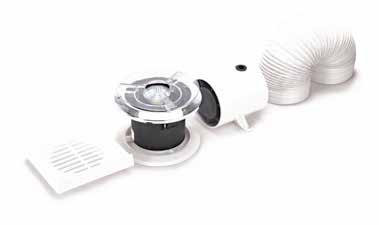
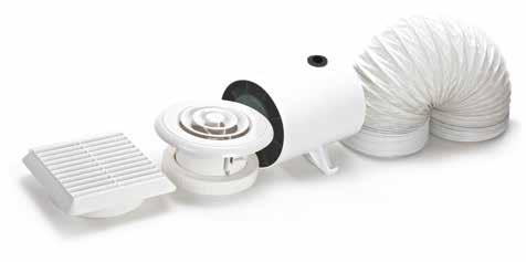
Duct kit options for easy installation
Complies with ErP Directive Building Regulations
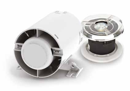
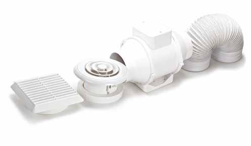
100mm (4”) SPV AXIAL KIT WITH LED SPOTVENT
Mounts in ceiling void/loft
Complies with ErP Directive Building Regulations

Mounts in ceiling void/loft
Key features
LED grilles included in specified kits
Very high air flow performance
Concealed fan for discreet operation
Quiet in operation
Ideal for longer duct runs and shower applications

Duct kit options enable easy installation
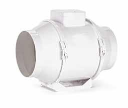
Key


CENTRIFUGAL FANS 100mm (4")


MOUNTS ONTO A WALL OR CEILING | REPLACEMENT FAN ONLY
Key features
Provides effective ventilation
Quiet in operation
Ideal for long duct runs up to 6m
Fire Damper Back Plate


Key features
Comply with current Building Regulation requirements
Offers a very low SFP down to 0.39 W/(l/s)
Quiet in operation
Stylish fascia to fit interior design scheme

Reduces carbon emissions
Complies with ErP Directive Building Regulations
Accessories
SPR405 Replacement Front Cover
MAY904A Surface Installation Back Box, Plastic
MAY905B Building in Wall Back Box
MAY906A Surface Installation Back Box, Metal MAYFD Fire Damper Back Plate
Get in touch for more information on our comprehensive range of ventilation systems and high quality ducting, including awardwinning thermal and unique Domus Adapt.
Please see the following step by step guide on how to select a fan unit. The extract rates are given as an example only, and the suitability of the product to meet all noise and Building Regulations for the proposed application should be confirmed. This is a basic guide and does not include selections based on specific fan power requirements under Part L of the Building Regulations etc.
Required information: Room size | Application
What is the room volume m³?
Example – 10m long x 5m wide x 2.5m high = 125m³
What is the application?
Example – Wall mounted in an office, six air changes necessary owing to size (see table above)
What is the flowrate calculation?
Room Volume m3 x air change = 750m3/h
To calculate the flow rate as m3/s divide your answer by 3600. Finally multiply the m3/s figure by 1000. This will leave you with your flow rate as l/s
e.g. 125m³ x 6 = 750m³/h 750 ÷ 3600 = 0.208m3/s 0.208m3/s x 1000 = 208l/s
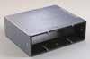
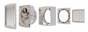
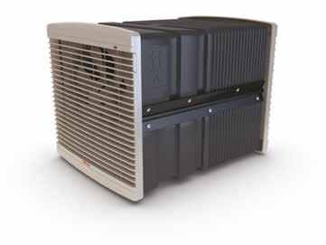
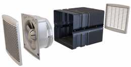
Available as kits or basic fan modules with adaptable ancillaries such as window spacers and weather terminals, our D Series Window fans can be part of a new install or refurbishment project.
Performance represents complete fan kit
Electrical and sound
Available in 6, 9 and 12”
Exposed site window installation (use with Window Fan Kit)
Fan Kit
Weather cowl can replace the external grille and window sealing plate
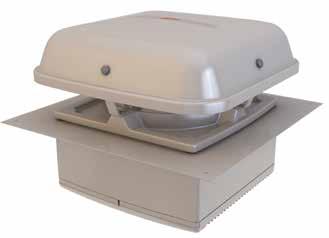
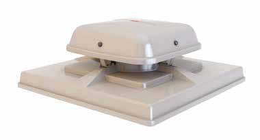
The low profile Pitched Roof kits are designed to be installed on angular roofs and suitable for all weather exposure.
Performance represents complete fan kit
Pitched Roof Cowl
Spacer
Pitched roof (ducted to ceiling) installation (use with Pitched Roof Fan Kit)
Roof Cowl (from kit) Fan Spacer (from kit)
Dimensions (mm)
Fan module (from kit) Single spigot adapter required
For details of ducting and accessories, please contact us
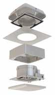
Complementing the Pitched Roof offering, these fan kits ensure the D Series portfolio is comprehensive and practical in application.
Flat roof (ducted to ceiling) installation (use with Ceiling Fan Kit)
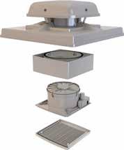
Roof Cowl (from kit)
Dimensions (mm)
O/A height above roof – D
Depth of roof construction – C
Depth of Fan – B
A = Opening size, B = Overall size
Fan Spacer & Fan Module (from kit)
Single spigot adapter required
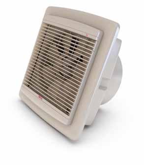
An ultra quiet wax thermo actuator combines with highly innovative motor and impeller technology to produce one of the quietest wall fans available.
Performance represents complete fan kit
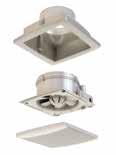
A discreet design, suitable for solid or panel ceilings. These fans can be installed with our Roof or Weather Terminals, allowing optional exhaust points for flexible application.

Note:
u Up to five fans (size 6”/ 9”) can be controlled by one DX-CON. Up to two fans (size 12”) can be controlled by one DX-CON u Do not mix different fan sizes on the same controller
Remote Sensors
module, internal grille
Used for exposed site installation 1 spacer. Use with weather terminals

For ducted systems.
To be mounted onto front of DX-WS
For exposed window installations. Use with DX-WS
No fan included Used for timber and thin walls, pitched roof and above ceiling. One fixing plate. Used with window kits spacers &/or weather terminals


For panel, ceiling or retro installations where uneven walls need to be fixed
external louvred grille
Fitting Remote Controller DX-CON or Remote Sensors (optional)
The DX-CON Multi-Fan Control provides supply or extract, variable speed and automatic or manual switching of several fans if desired.
The DX-CON should be positioned at least 1.5m above the floor and away from direct heat sources e.g. radiators.
NOTE:
u Up to five fans (size 6”/9”) can be controlled by one DX-CON
u Up to two fans (size 12”) can be controlled by one DX-CON
u Do not mix different fan sizes on the same controller
Typical code: DX-CON
NOTE:
If two x 12 inch fans or five x 6/9 inch fans are used in the same operating mode in the same room they should all be controlled from the same DX-CON speed control. This avoids the possibility of one fan (if speed controlled at a lower flow rate) being stalled by the other fan(s). Adequate make-up air provision sufficient to provide ventilation in accordance with building regulations is required in all rooms. This should be checked during commissioning with all fans in the same room running together in all possible configurations.
The automatic shutters, motor bearings should be frequently inspected and maintained to ensure they open fully/operate satisfactorily.
Speed Control – with ‘Economy’ (50%) setting, extract and supply, on/off switches.
Use of an RCD and fused spur with 1A, Bussmann TDC180, BS1362, fuse (Farnell order no: 1123029) for 1 fan or 2A, Bussmann TDC180, BS1362 fuse (Farnell order no: 1123032) for two or three fans is recommended. Always confirm airflow direction before commissioning.
The DX-RH remote humidity sensor should be positioned at least 1.5m above the floor and away from direct heat sources e.g. radiators.
Fan operated by On/Off switch
Basic fan operated by Remote Sensor
u Connect link wire between L2 & L4 for extract, or
u Connect link wire between L2 & L3 for supply
Fan operated by Integral Sensor
u Connect link wire between L2 & L4 for extract, or
u Connect link wire between L2 & L3 for supply
Supply / extract fan operated via Remote DX-CON Control
u Connect link wire between L2 & L4 for extract, or
u Connect link wire between L2 & L3 for supply
u Connect switched live signal to L5 for integral timer, module
Supply / extract fan operated via Remote DX-CON Control & Remote Sensor(s)
u Remote switch may be set: On / Off, Extract / Supply
u Economy / Std. (variable speed), Auto / Manual
Supply / extract fan operated via Remote DX-CON Control and Integral Sensor
u Remote switch may be set: On / Off, Extract / Supply, Economy / Std. (variable speed), Auto / Manual
u One or more Remote Sensors may be wired in parallel to one DX-CON Control
Note: Multi-fan options:
u Up to five fans (size 6” / 9”) can be controlled by one DX-CON. Up to two fans (size 12”) can be controlled by one DX-CON. Do not mix different fan sizes on the same controller
u Remote switch may be set: On / Off, Extract / Supply, Economy / Std. (variable speed), Auto / Manual
u Maximum one Integral Sensor per fan 6/9/12 denotes unit size identity
u Humidity Sensor: DX-H6/9/12
u Passive Infra Red Sensor: DX-PIR6/9/12
u Run on Timer: DX-T6/9/12
u A single sensor will switch all fans if more than one fan is being operated by a single DX-CON controller
Multiple fans operated via remote DX-CON control
Multiple fans operated via remote DX-CON control and one Integral Sensor in Fan 1
Remote switch may be set:
u On / Off, Extract / Supply, Economy/ Std. (variable speed), Auto / Manual
Additional fans may be added, up to limit of control:
u Up to five fans (size 6” / 9”) can be controlled by one DX-CON
u Up to two fans (size 12”) can be controlled by one DX-CON
u DX-CON Do not mix different fan sizes on the same controller
Multiple fans operated via remote DX-CON control and a Remote Sensor
Remote switch may be set:
u On / Off, Extract / Supply, Economy / Std. (variable speed), Auto / Manual
Multiple fans operated via remote DX-CON control and one Integral Sensor in Fan 1
Additional fans may be added, up to limit of control:
u Up to five fans (size 6” / 9”) can be controlled by one DX-CON
u Up to two fans (size 12”) can be controlled by one DX-CON
u DX-CON Do not mix different fan sizes on the same controller
Fan operated using remote DX-CON control and a Multiple Remote Sensor
Remote switch may be set:
u On / Off, Extract / Supply, Economy/ Std. (variable speed), Auto / Manual
Additional fans may be added, up to limit of control:
u Up to five fans (size 6” / 9”) can be controlled by one DX-CON
u Up to two fans (size 12”) can be controlled by one DX-CON
u Do not mix different fan sizes on the same controller
Remote switch may be set:
u On / Off , Extract / Supply, Economy/ Std. (variable speed), Auto / Manual
Fans shall be located in the positions indicated on the drawings and in accordance with the relevant fan schedule.
The fan shall be of the D SERIES type and shall be supplied complete with integrated low loss radial backdraught shutter, silent operation via a thermo actuator, room side grille, connection kit and external louvre/roof cowl to suit the particular application.
The high efficiency, low noise axial flow impeller shall be directly driven by an external rotor motor featuring enclosure protection to IP 44, class B winding insulation and maintenance free ball bearings.
All models shall be suitable for air over motor temperatures of up to 60°C and 95% R.H (non-condensing). The motor and impeller shall be dynamically balanced as an assembly.
Fan casing, impeller and shutter shall be manufactured from UV stabilised ABS polymer. All models shall include an economy/ high efficiency setting facility and are dove grey in colour.
The fan shall be provided complete with integrated or remote controls as detailed in the schedule and as described below.
Where indicated the fans shall be interlinked and controlled from 1No. DX-CON (up to five fans in sizes 6 & 9, up to two fans size 12).
Fans shall be reversible via reversing switch on DX-CON fan controller.
Fan to have a manufacturer’s 2 year warranty.
Fan to be of the D SERIES type as manufactured by Domus Ventilation.
The fan shall be provided with either an integrated sensor to activate the fan, or one of the remote options.
Integrated control options:
u DX-T(size) Run-on timer, adjustable between 2-40 minutes
u DX-H(size) Humidity sensor (30-90%). Includes run-on timer 2-40 minutes
u DX-PIR(size) PIR sensor, includes run-on timer 2-40 minutes
Remote control options:
u DX-RH Humidity sensor 30-90%. Includes run-on timer 2-40 minutes
u Anti-tamper security strap
u DX-CON controller incorporating economy switch, reversing switch and rotary speed control
Where indicated the fans shall be interlinked and controlled from 1No. DX-CON (up to five fans in sizes 6 & 9, up to two fans size 12)
Do not mix different fan sizes with same controller
Fan, integrated controls or associated sensors/controllers shall be as manufactured by Domus Ventilation, all with a 2 year warranty
The manufacturer’s recommendations should be observed at all times
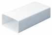
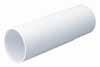
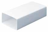
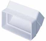
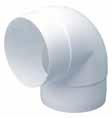
As a branch based system, rigid duct is ideal for new-build or for where space isn’t restricted and can be used with MVHR, MEV, dMEV or intermittent extract.
Available in six different profiles to suit any application
Comes with a full set of adapters to enable a simple or complex system
100mm (4")
What depth is available for the duct?
High levels of air tightness and system efficiency
Supported by patented duct insulation, fire stopping and sound attenuation components


Appliance duct connection size
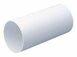
125mm (5")
What depth is available for the duct?
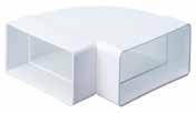
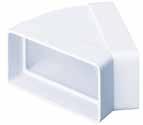
Range includes high efficiency duct bends, designed to reduce duct resistance and overall system energy usage
Material Flammability Class V0 to BS EN 60695-11-10, 50W Horizontal and Vertical flame test methods
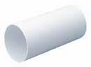
150mm (6")
When a profile has been specified and the duct layout designed, the system resistance must be calculated to ensure that the appliance has sufficient power to more than match the resistance of the complete system.
Where components are listed with one of three connection profiles; Male, Female or Duct.
Male: The fitting will fit inside duct.
Female: The fitting will fit around duct.
Duct: The connection profile is the same as the duct and may need a Female or Male straight connector to couple to duct.
NOTE. UL94 is now harmonised with BS EN 60695-11-10. So either UL94-V0 or Class V0 to BS EN 60695-11-10 would be equivalent.
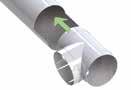
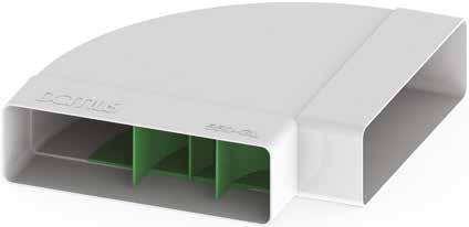
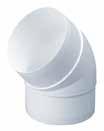
Engineered to significantly reduce duct resistance, lower system noise and overall energy usage. Domus Green Line bends are an innovative solution for a well designed and energy efficient duct system.
Smoothly channels air through the duct bend in a uniform flow
Performance has been tested by the Building Research Establishment (BRE)
Reduces duct resistance by up to 60% to lower the system’s pressure drop and overall energy usage
Reduced air speed through the bend to lower system noise
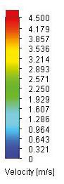
Owing to the profile of a duct bend, air travelling through it can become turbulent, causing increased resistance and system noise. As a consequence, the mechanical ventilation appliance will need to work harder in order to meet the required air flow rates; therefore, consuming more energy.
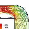
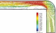
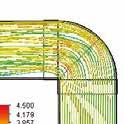
Domus Ventilation Green Line high efficiency 90° duct bends have been specifically designed to enable a uniform flow of air through the section of duct, reducing the duct resistance by up to 60% and lowering the air speed. All of which results in a quieter and more efficient ventilation system.
Performance has been tested by the Building Research Establishment (BRE).
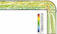

Typical air flow through a standard bend
Typical air flow through a Domus Green Line bend
All performance data has been taken from BRE Test Report PR0393-1004:2015.

For further information, please contact our Design Team at vent.projects@domusventilation.co.uk
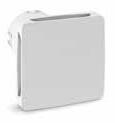
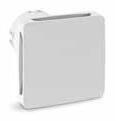
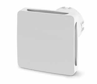
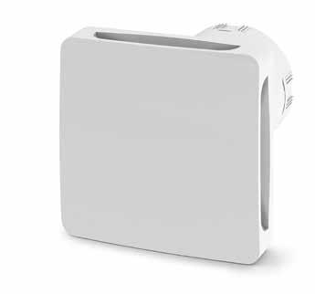
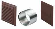
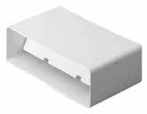
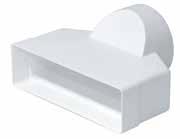
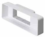
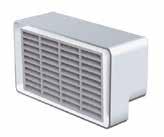
Domus Ventilation End Caps provide a quick and easy way of terminating a duct run with an air tight seal.
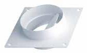
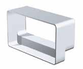
For installation between the duct run and external terminal, these wall plates are a simple way to ensure the duct is securely supported and held in place.
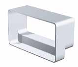
Duct clips are an effective part of the overall duct system and quick and easy to fasten into place. Domus Ventilation Duct Clips securely hold duct runs and prevent them from boeing.
*Two components per fitting required
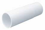
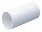
Domus rigid duct is manufactured from exacting tolerances to virtually eliminate air leakage and reduce pressure drop.
Domus EasiPipe 100 is suitable for Bathroom, Toilet and Utility room applications Duct
For further information, please contact our Design Team at vent.projects@domusventilation.co.uk
For installation between the duct run and external terminal, these wall plates are a simple way to ensure the duct is securely supported and held in place.
100 /125 and 150mm duct size clips are effective part of the overall duct system and quick and easy to fasten into place, Domus Duct Clips securely hold duct runs and prevent them from boeing.
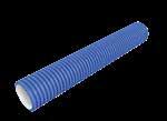
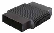
Key features
Recommended in both the Building Regulations and NHBC Standards
u Removes condensation risks from unheated areas
u Real advantages over using insulated hose
u Simple to install and handle
u Cost effective solution
u Specifically designed for ventilation applications
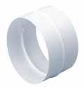
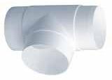
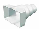
In-line Adapter, Rectangular to Round (110x54 – Ø100mm)
110x54 – Ø100mm
In-line Adapter, Rectangular to Round (204x60 – Ø100mm)
204x60 – Ø100mm
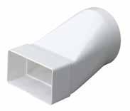
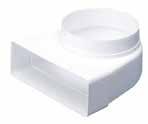
In-line Adapter, Rectangular to Round (204x60 – Ø125mm)
204x60 – Ø125mm
In-line Adapter, Rectangular to Round (220x90 – Ø150mm)
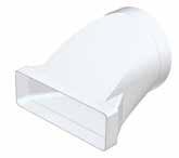
220x90 – Ø150mm
In-line Adapter, Rectangular to Round (227x133 – Ø100, Ø125, Ø150mm)
Performance data for double airbrick (code 954) with adapter (954)
227x133mm –Ø100, Ø125, Ø150mm
Performance data for Supply (air from outside)
Performance data for Extract (air to outside)
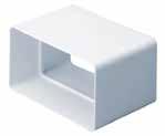
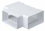
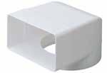
In-line Adapter, Rectangular to Rectangular (204x60 – 110x54mm)
204x60 – 110x54mm
In-line Adapter, Rectangular to Rectangular (220x90 – 204x60mm)
220x90 – 204x60mm
In-line Adapter, Rectangular to Rectangular (220x90 – 204x60mm)
220x90 – 204x60mm
data in Pascals (Pa)
In-line Adapter, Rectangular to Rectangular (227x133 – 220x90mm)
227x133 – 220x90mm
Performance data for Supply (air from outside)
Performance data for Extract (air to outside)
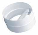
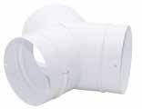
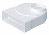
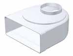
Fixed Spigot Plenum, Rectangular to Round (204x60 – Ø125mm)
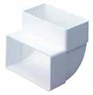
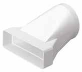
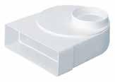
Offset Rotating Spigot, Rectangular to Round (204x60 – Ø100mm)
data in Pascals (Pa)
A = spigot furthest from socket, B = spigot nearest to socket 204x60 – Ø100mm
data for Supply (air from outside)
(A) 300mm length pipe
(B) 2000mm length pipe
Offset Rotating Spigot, Rectangular to Round (204x60 – Ø125mm)
data for Extract (air to outside)
A = spigot furthest from socket, B = spigot nearest to socket 204x60 – Ø125mm
Performance data for Supply (air from outside)
(A) 300mm length pipe
(B) 2500mm length pipe
Performance data for Extract (air to outside)
(A) 300mm length pipe
(B) 2500mm length pipe
Offset Rotating Spigot, Rectangular to Round (204x60 – Ø150mm)
– Ø150mm
A = spigot furthest from socket, B = spigot nearest to socket
220x90 – Ø100mm
A = spigot furthest from socket, B = spigot nearest to socket
Performance data for Supply (air from outside)
(A) 300mm length pipe
(B) 3000mm length pipe
Performance data for Extract (air to outside)
(A) 300mm length pipe
(B) 3000mm length pipe
Performance data for Extract (air to outside)
Offset Rotating Spigot, Rectangular to Round (220x90 – Ø150mm)
– Ø150mm

Performance data for Supply (air from outside)
Performance data for Extract (air to outside)

Technical drawing support


Nationwide sale coverage

National distribution
After sales support
Engineered to include an integral flow control device, enabling connection to a range of stylish architectural grilles – no air valves necessary.
Enables commissioning to be carried out prior to fixing ceiling boards
Adjusting the air terminal for commissioning is quick and easy
Allows simple connection to architectural grilles – no air valves necessary
Integral flow control device cannot be easily tampered with – reducing the risk of impacting system performance and indoor air quality
Commissioning rates can be agreed prior to ceilings being fixed; enabling that air flow rates will be achieved (if fitted correctly) and less risk of costly remedial work
Ability to integrate stylish grilles to fit interior design scheme
540-FC Domus Supertube Rigid Duct 204x60mm Flow Control Plenum for Architectural Grilles White
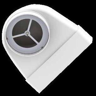
To help adjust the integral flow control device for commissioning and balancing, we also offer a Flow Control Adjustment Kit – code FCAK1
The kit contains a long reach spanner and allen key.
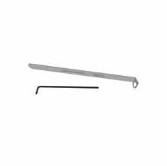
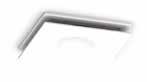
Code Description
FCAK1 Domus Radial Flow Control Adjustment Kit Silver
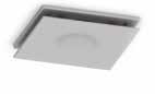
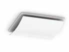

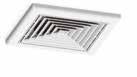
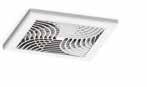
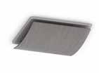
Stylish bathroom and kitchen fan fascias, designed to complement modern interior design schemes.
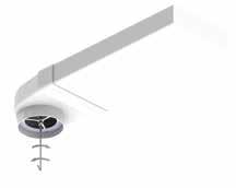
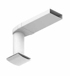
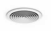
Suitable for 125mm connection.
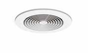 540-FC with grille
FCAK1 in use
ART125-CF1BM
ART125-CF1W
ART125-CF1S
ART125-DT1S
ART125-SD2W
ART125-DT1W
ART125-SD1W
5907W
ART125-CD1W
540-FC with grille
FCAK1 in use
ART125-CF1BM
ART125-CF1W
ART125-CF1S
ART125-DT1S
ART125-SD2W
ART125-DT1W
ART125-SD1W
5907W
ART125-CD1W
Our Rigid Duct Attenuators offer excellent sound absorption over a range of audible frequencies.
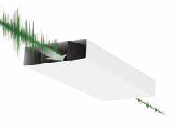
Our rigid duct sound attenuator range now includes variants with even better sound attenuation performance, at the levels which count – the frequency in which roomto-room cross talk and appliance noise are more prominent to our hearing!
Best performing plastic attenuation on the market
Excellent sound attenuation properties as verified by the Sound Research Laboratories (SRL)
Tamper proof
Significantly reduces transmitted appliance noise and room-to-room cross talk
Noise generated by a mechanical extract appliance could result in occupants incorrectly altering the performance of their system and, as a consequence, detrimentally impacting indoor air quality
To avoid this, Building Regulations stipulate that the system should not produce excessive noise that could discourage occupants from using it correctly
In addition to this, resident cross talk carried through connecting roomto-room ducting can also impair homeowner comfort
Rigid duct attenuators can be installed in roof and ceiling voids and are recommended to be fitted on the room-side of the ventilation appliance, to limit cross talk and to be near each inlet and outlet.
Protected foam helps enable a long life, clean and fresh ventilation system
Low profile increases installation options and offers greater flexibility
Lightweight and easy to fit for quicker installation time
Can also be used with Domus Thermal duct insulation
To support the most popular rectangular rigid duct profiles our attenuators are available to install with 204x60mm and 220x90mm duct systems.

The attenuator can bolt together with connector 520 or 920 to increase length.
Duct attenuator: PVC plastic ducting Acoustic Foam Material: High Density Reconstituted PVC/Nitrile Foam with a density of 240kg/m3. Foam contains a unique uniform cell structure, offering excellent sound absorption properties, particularly at low frequency.
Flame Retardant, compliant to BS476 Part 7 Class 1, UL94-HF1, UL94-V0 (tested by Warrington Bodycote) and FMVSS 302.
Helps facilitate occupant acceptance of a continuously running centralised ventilation system

Helps achieve Building Regulation recommendations
The installation of Domus Ventilation rigid duct attenuators over metal alternatives, provides peace of mind that future replacement owing to corrosion won’t occur
Approved Document F of the Building Regulations F1 Means of Ventilation recommends that the system should not produce excessive noise that could discourage occupants from using it correctly. A rigid duct attenuator should, therefore, form part of duct system, to ensure occupants do not incorrectly alter the performance of the system and as a consequence, detrimentally impact indoor air quality.
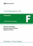
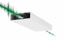
The diagrams illustrate the increased sound absorption levels when close-coupling up to three individual 0.5m lengths of rigid duct attenuators, thus reducing noise levels by up to 55dB.
As an integral part of Domus rigid duct systems, Domus Thermal™ is a unique and patented duct insulation solution. Designed specifically to radically improve the thermal insulation of rigid duct passing through unheated spaces in domestic properties.
A range of EPS insulation components specifically designed to insulate round or rectangular domestic ventilation ducting passing through cold areas
A method of significantly reducing heat loss and virtually eliminating the formation of condensation
The first engineered duct insulation system available to comply with recent improvements to Building Regulations
Approved Document F of Building Regulations 2021 states that all ducting installed in domestic properties, which passes through unheated areas or loft spaces, should be insulated with the equivalent of at least 25mm of a material having a thermal conductivity of ≤0.04 W/(m.K) to reduce the possibility of condensation forming
The loss of heat through poorly insulated duct systems means that modern homes are at risk of losing a valuable source of energy; for example, when using warm exhaust air to heat fresh incoming air through an MVHR system or exhaust air heat pump
Domus Thermal exceeds these regulations, having a thermal conductivity of 0.03 W/(m.K), thus providing better insulation and peace of mind that the system will be compliant and save energy. This greatly improved thermal conductivity allows the wall thickness to be reduced to just 20mm in most profiles
Regulations
The only engineered duct insulation solution which complies with 2021 Building Regulations. The thermal performance of the range, in relation to 2021 Building Regulations, has been independently ratified by one of the UK’s leading thermodynamics experts.
Building Regulations demand: ≤0.04 W/(m.K) thermal conductivity at 25mm insulation thickness.
Minimum thermal resistance or R-value = 0.025/0.04 = 0.625 K/W.
Domus Thermal provides:
≤0.03 W/(m.K) thermal conductivity at 20mm insulation thickness.
Minimum thermal resistance or R-value = 0.020/0.03 = 0.666 K/W.
The increased thermal resistance of Domus Thermal, therefore, exceeds current Building Regulations.
Currently, compliant solutions are more labour intensive and require higher skill levels to install. Domus Thermal’s simple interlocking feature means that the system is quicker and easier to install. This revolutionary method can, therefore, significantly reduce installation costs.
Domus Thermal is available in a range of profiles and fittings to insulate the Domus EasiPipe (round) and Supertube (rectangular) duct systems.
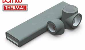
To support the system, PVC coated, perforated steel banding is also available for surface mounting or suspending the insulated system. The use of this soft-edged fixing system is strongly recommended to ensure that the insulated duct is held securely without damage.
The interlocking feature and regular external profile provides homeowners with a neat, professional and continuous appearance.
An installer-friendly solution which can be fitted quickly and reliably without the need for gluing or tapingDomus Thermal is manufactured from flame retardant (EN 13163 class E) Silver EPS (expanded polystyrene), which provides its enhanced thermal insulation properties and enables the system to exceed the requirements of the current Building Regulations.
Injection moulded, carbon impregnated Expanded Polystyrene (EPS)
Density = 25kg/m³
Colour: Silver/Grey
Wall thickness 20mm and 22.25mm*
Components to suit 100mm internal diameter Domus EasiPipe system
Components to suit 125mm internal diameter Domus EasiPipe system
Components to suit 150mm internal diameter Domus EasiPipe system
Components to suit 204mm x 60mm Domus Supertube system
*22.25mm wall thickness only applies to 1m lengths of 204mm x 60mm
The Silver EPS used to manufacture Domus Thermal provides a significantly improved thermal conductivity value owing to the inclusion of carbon particles, which gives Domus Thermal its distinctive silver colour.
Domus Thermal products are recyclable and when installed in accordance with Domus Ventilation’s installation guidelines, Domus Thermal offers a life expectancy greater than or equal to that of the Domus duct system.
Reaction to Fire Class E to BS EN 13501-1, Fire classification of construction products and building elements.
NOTE. The thermal duct itself conforms to BS EN 13163. Which under section 4.2.8 references the EN 13501-1 for the reaction to fire test standard. Flame retardant to Class E of EN13163.
The thermal duct itself conforms to BS EN 13163. Which under section 4.2.8 references the EN 13501-1 for the reaction to fire test standard.
TS22 (coated) and TS22G (not coated)
We offer a choice of coated or uncoated steel banding to support Domus Thermal. Suitable for surface mounting or suspending the insulated system
Domus Thermal is available in a range of profiles and fittings to insulate the Domus EasiPipe (round) and Supertube (rectangular) duct systems. To support the system, PVC coated, perforated steel banding is also available for surface mounting or suspending the insulated system. The use of this soft-edged fixing system is strongly recommended to ensure that the insulated duct is held securely without damage.
Product Code Description
TS1100-4 Ø100mm Round Pipe Duct Insulation 1m
TS1100-5 Ø125mm Round Pipe Duct Insulation 1m
TS1100-6 Ø150mm Round Pipe Duct Insulation 1m
TS490 Ø100mm Round 90º Bend Duct Insulation
TS590 Ø125mm Round 90º Bend Duct Insulation
TS690 Ø150mm Round 90º Bend Duct Insulation
TS491 Ø100mm Round 45º Bend Duct Insulation
TS591 Ø125mm Round 45º Bend Duct Insulation
TS691 Ø150mm Round 45º Bend Duct Insulation
TS492 Ø100mm Round Equal T Piece Duct Insulation
TS592 Ø125mm Round Equal T Piece Duct Insulation


TS692 Ø150mm Round Equal T Piece Duct Insulation

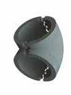


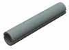
Product Code Description
TS510 204 X 60mm Channel Duct Insulation 1m

TS910 220 X 90mm Channel Duct Insulation 1m
TS550
TS950
X 60mm Horizontal 90º Duct Insulation
TS582
X 60mm Horizontal T Piece Duct Insulation
TS982 220 X 90mm Horizontal T Piece Duct Insulation

TS575 204 X 60mm Vertical 45º Bend Duct Insulation
TS975 220 X 90mm Vertical 45º Bend Duct Insulation
TS540 204 X 60mm Fixed Spigot Ø125mm Plenum Duct Insulation
TS961 220 X 90mm Fixed Spigot Ø125mm Plenum Duct Insulation
Domus Ventilation offers fire solutions to prevent the spread of fire where rigid ducting penetrates fire compartment walls. The range includes horizontal and vertical sleeves.
All Domus Ventilation plastic ductwork will meet UL94VO (duct) and UL94HB (fittings) flammability standard. Operating temperatures of -15˚C to 60˚C
For installation and technical information visit: www.quelfire.co.uk
Rectangular profiles are very slimline, saving ceiling space
Suitable for masonry walls or plasterboard partitions
Suitable for multiple applications e.g insulated and non-insulated partitions Can be retrofitted
No mechanical fixings required Robust galvanised steel shell
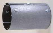
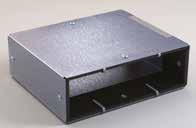
Fire Collars assist with preventing the spread of fire where Domus Rigid Ducting penetrates fire compartment walls. These help to gain regulation compliance.
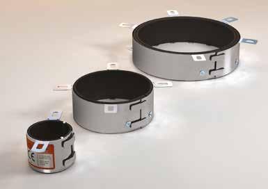
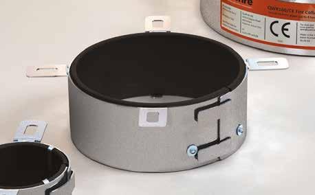
Key features
Available for Ø100mm, Ø125mm and Ø150mm ducting
Can be retrofitted
Robust galvanised steel shell
Ø125mm
Note: For horiztonal use only. One unit should be fitted on each side of the wall following all manufacturers’ installation instructions. Our range of fire wrap products are designed to be installed on straight rigid PVC ducting lengths only. For further information, please contact Domus Ventilation for technical data and installation documents.
Recessed ceiling air valves are widely used in both domestic and commercial buildings. Ceilings must be fire protected in accordance with Approved Document B of the Building Regulations 2021.
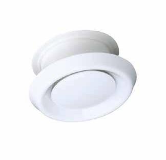
Once a hole is made in a ceiling for an air valve, the integrity of the construction and its ability to perform in a fire is reduced significantly. This must be fire-stopped to reinstate the original fire rating of the ceiling.
The popularity of whole-house ventilation and controlled ventilation is increasing. This results in an increased number of penetrations through fire compartment walls and floors producing open pathways for the passage of both smoke and fire.
Ceiling air valves, if left unprotected, can allow a fire to spread rapidly through a building.
Meet the requirement of Building Regulations Approved Document B
Maintains integrity of fire rated ceilings for up to 60 minutes
Alternative to more expensive fire dampers
Fits in exactly the same way as a standard metal air valve
Air flow is unaffected
Easy to retrofit in place of existing metal air valves
Highly cost effective
Successfully tested for 60 minutes according to BS EN 1365-2:1999 & BS 476 Test report number: BTC 18074F
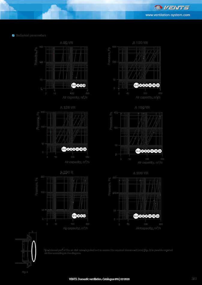
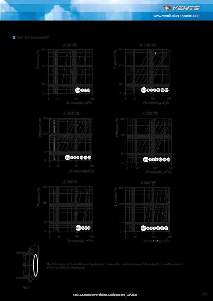
The Domus Ventilation Solis Air Brick has been designed as a non-combustible air brick to maintain low resistance and comply with the latest standards set out in Approved Document B (fire safety).
The range consists of three versions: 204x60, 220x90 and 220x126 to accommodate all external wall types.
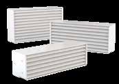
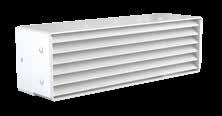
Non-combustible as set out in Approved Document B (fire safety)
204x60, 220x90 and 220x126 options
Low resistance
Compatible with Domus Rigid and Thermal ducting range
Air brick powder coating pre-qualified to EN13501-1 classification A2-s1,d0
Air brick material 1.5mm galvanised steel, fire class A1
‘no contribution to fire’
Metal air duct material 0.8mm galvanised steel, fire class A1
‘no contribution to fire’
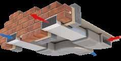
With the changes in Building Regulations, Domus Ventilation offers a FREE CIBSE approved CPD which runs through Building Regulations and how the new non-combustible air brick can integrate into your projects. Contact us for more information.
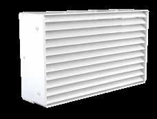
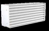
All items are to be purchased separately. Assembly to be carried out on site by installer.
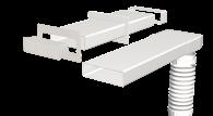
Domus Ventilation is the complete solution provider of duct and accessories, offering guaranteed compatibility, compliant with regulations, quality of fit and peace of mind! Rigid duct Flexi duct
Radial duct
Thermal duct
Tape, sealant and screws
The colour options are applicable to the low resistance metal air bricks only.
Need a bespoke colour? Just send us the RAL number and we can do this for you!
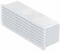
Description
u Airbrick with Damper, 204mm x 60mm spigot (male)
u Exhaust (air to atmosphere)
Material
u HIPS (High Impact Polystyrene)
Colour
u White (RAL9016)
u Brown (RAL8011)
u Terracotta (RAL8004)
u Cotswold (RAL1014)
u Grey (RAL7046)
u Black (RAL9017)
Why metal external air bricks? This has been brought in owing to legislation changes, Part B fire regulations have recently changed and now confirm that no combustible material i.e. pvc is to be installed within or on external surface of an external wall above 11m in Scotland and above 18m in England and Wales, therefore, giving us no option but to design and manufacture a metal version.
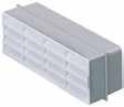
Description
u Airbrick with 204mm x 60mm spigot (female)
u Exhaust (air to atmosphere)
u Intake (air from atmosphere)
Material
u HIPS (High Impact Polystyrene)
Colour
u White (RAL9016)
u Brown (RAL8011)
u Terracotta (RAL8004)
u Cotswold (RAL1014)
u Grey (RAL7046)
u Black (RAL9017)
Why metal external air bricks? This has been brought in owing to legislation changes, Part B fire regulations have recently changed and now confirm that no combustible material i.e. pvc is to be installed within or on external surface of an external wall above 11m in Scotland and above 18m in England and Wales, therefore, giving us no option but to design and manufacture a metal version.
Description
u Double Airbrick with 220mm x 90mm spigot (female)
u Exhaust (air to atmosphere)
977 adapter on end of ducting to 905B
u Intake (air from atmosphere)
977 adapter on end of ducting to 905B
Material
u HIPS (High Impact Polystyrene)
Colour
u White (RAL9016)
u Brown (RAL8011)
u Terracotta (RAL8004)
u Cotswold (RAL1014)
u Grey (RAL7046)
u Black (RAL9017)
Intake Exhaust
Cubic equation to derive pressure drop = 0.0011x2 - 0.0117x + 0.0895
Cubic equation to derive pressure drop = 0.0057x - 0.0044
Performance data from Test Report TR1622
data
Why metal external air bricks? This has been brought in owing to legislation changes, Part B fire regulations have recently changed and now confirm that no combustible material i.e. pvc is to be installed within or on external surface of an external wall above 11m in Scotland and above 18m in England and Wales, therefore, giving us no option but to design and manufacture a metal version.
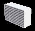
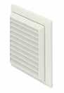
u Fixed Louvre Grille with 100mm circular spigot (male)
u Exhaust (air to outside)
u Intake (air from outside)
u HIPS (High Impact Polystyrene)
Colour
u White (RAL9016)
u Brown (RAL8011)
u Terracotta (RAL8004)
u Cotswold (RAL1014)
u Grey (RAL7049)
u Black (RAL9017)
Cubic equation to derive pressure drop = (-1.77010-5V3) + (0.0062V2) + (0.005V) - 0.006
Cubic equation to derive pressure drop = (-3.40310-5V3) + (0.0241V2) - (0.001V) + 0.007
Performance data from BRE Test Report PR0393-1004:2015
Why metal external air bricks? This has been brought in owing to legislation changes, Part B fire regulations have recently changed and now confirm that no combustible material i.e. pvc is to be installed within or on external surface of an external wall above 11m in Scotland and above 18m in England and Wales, therefore, giving us no option but to design and manufacture a metal version.
u Architectural Grille with 125mm circular spigot (male)
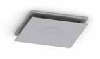
u Extract (air from rooms)
u Supply (air to rooms)
u HIPS (High Impact Polystyrene)
u Silver
Intake Exhaust
Cubic equation to derive pressure drop = 0.0055x2 + 0.0371x - 0.1038
Cubic equation to derive pressure drop = 0.0125x2 - 0.008x - 0.0354
Performance data from Test Report TR1622
Why metal external air bricks? This has been brought in owing to legislation changes, Part B fire regulations have recently changed and now confirm that no combustible material i.e. pvc is to be installed within or on external surface of an external wall above 11m in Scotland and above 18m in England and Wales, therefore, giving us no option but to design and manufacture a metal version.
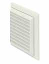
Description
u Fixed Louvre Grille with 125mm circular spigot (male)
u Exhaust (air to outside)
u Intake (air from outside)
Cubic equation to derive pressure drop
Material
u HIPS (High Impact Polystyrene)
Colour
u White (RAL9016)
u Brown (RAL8011)
u Terracotta (RAL8004)
u Cotswold (RAL1014)
Performance data from BRE Test Report PR0393-1004:2015
Why metal external air bricks? This has been brought in owing to legislation changes, Part B fire regulations have recently changed and now confirm that no combustible material i.e. pvc is to be installed within or on external surface of an external wall above 11m in Scotland and above 18m in England and Wales, therefore, giving us no option but to design and manufacture a metal version.
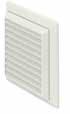
u Fixed Louvre Grille with 150mm circular spigot (male)
u Exhaust (air to outside)
u Intake (air from outside)
Cubic equation to derive pressure drop = (-2.92110-6V3) + (0.0015V2) + (0.007V)
Polystyrene)
Colour
u White (RAL9016)
u Brown (RAL8011)
u Terracotta (RAL8004)
u Cotswold (RAL1014)
Cubic equation to derive pressure drop = (5.18210-6V3) + (0.0049V2) + (0.013V) - 0.030
Performance data from BRE Test Report PR0393-1004:2015
Why metal external air bricks? This has been brought in owing to legislation changes, Part B fire regulations have recently changed and now confirm that no combustible material i.e. pvc is to be installed within or on external surface of an external wall above 11m in Scotland and above 18m in England and Wales, therefore, giving us no option but to design and manufacture a metal version.
We offer a wide range of stylish architectural grilles for internal and external use.
Where fittings are available in different colours:
110x54mm System
RAL Reference and
White Traffic White RAL 9016 Brown Nut Brown RAL 8011
Cotswold Ivory RAL 1014
RAL
Terracotta Copper Brown RAL 8004 Black Traffic Black RAL 9017 Grey Telegrey 2 RAL 7046
Rigid Duct Outlet Louvered Grille with Flyscreen White H155xW155xD40 Male
F4905B Rigid Duct Outlet Louvered Grille with Flyscreen Brown H155xW155xD40 Male
F4905C Rigid Duct Outlet Louvered Grille with Flyscreen Cotswold H155xW155xD40 Male
Why metal external air bricks? This has been brought in owing to legislation changes, Part B fire regulations have recently changed and now confirm that no combustible material i.e. pvc is to be installed within or on external surface of an external wall above 11m in Scotland and above 18m in England and Wales, therefore, giving us no option but to design and manufacture a metal version.
Ø100mm System
Soffit Vent
Why metal external air bricks? This has been brought in owing to legislation changes, Part B fire regulations have recently changed and now confirm that no combustible material i.e. pvc is to be installed within or on external surface of an external wall above 11m in Scotland and above 18m in England and Wales, therefore, giving us no option but to design and manufacture a metal version.
Why metal external air bricks? This has been brought in owing to legislation changes, Part B fire regulations have recently changed and now confirm that no combustible material i.e. pvc is to be installed within or on external surface of an external wall above 11m in Scotland and above 18m in England and Wales, therefore, giving us no option but to design and manufacture a metal version.
The Universal Service Terminal is suitable for use in all tiled and slated pitched roof styles without the need to identify the make or design of the tiles or slates. The unit comprises a flat box hood on a circular upstand, a 500mm x 500mm flashing skirt of non-lead material and a stepped adapter that allows connection to 100mm, 110mm, 125mm, 150mm and 160mm ventilation pipe. This unit can also be used to vent soil and vent pipes where an external pressure test is not required.
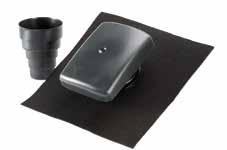
The free areas and pressure/airflow readings are as follows:
Large diameter spigot c/w
Adapter to accept ducting of 100/110/125/150/160mm
20,000mm² large free vent area
Suitable for most tiled and slated pitched roofs
Not suitable for flat roof application
The unit is easy to install – the adapter is simply cut at the required diameter step and attached to the undertile spigot with solvent weld/PVC glue. The flashing material allows fitting into most tiles and slates.
Flashing skirt manufactured from non-lead material
Terminal, Box and Adapter manufactured from UPVC and Ubiflex
SEND US YOUR PROJECT DETAILS AND RECEIVE:
An assigned estimator/designer who will become your direct point of contact
FREE OF CHARGE drawings available in AutoCAD or Revit A full BOM (bill of materials)
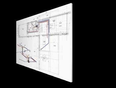
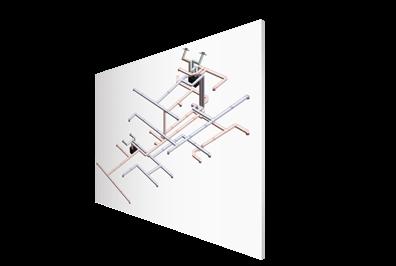
Scheduled, nation-wide delivery
Ongoing technical support when our product is on site
Whole house air distribution systems, which provide simple, quick and hassle free installation, to save time and money.
Domus Radial systems are a clever plug and play whole house ventilation solution, which use manifold distribution to evenly service each room through semi-rigid duct. These systems incorporate a centralised mechanical unit; either a Mechanical Ventilation with Heat Recovery (MVHR) or Mechanical Extract Ventilation (MEV).
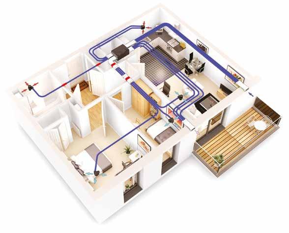
Slimline manifold (125mm deep) enables easy installation between joists or in tight spaces, where required for larger developments
Optional integral flow control device allows the outlet plenum to be connected directly to a stylish architectural grille – no air valve necessary
Rapid fixing mechanism enables secure and air-tight connection with no leakages
Corrugated construction and the unique formulation of semi-rigid duct resists stress cracking and on-site damage
Perfect ventilation choice for all residential dwellings
Can integrate with Domus rigid duct systems to create versatile hybrid solutions
Fire-stopping and insulation components also available
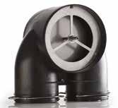
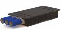
Tested by the Building Research Establishment (BRE) for inclusion within the Product Characteristics Database, Domus Radial offers performance levels that not only are the equivalent to traditional rigid ducting in smaller builds, but also exceed these levels in properties with four or more wet rooms.
Our award winning Domus Radial semi-rigid duct systems provide simple, quick and hassle free design and installation which saves time and money, whilst maximising in-situ performance.
Radial duct is up to 60% quicker and easier to install, against traditional, saving you time and money
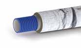
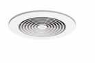
Easy to order pre-selected house packs enable straightforward specification and selection
Eliminates room-to-room cross talk, for a quieter home
Simplified design layout makes the system ideal for new and refurb projects
Increased air capacity for reduced air noise, low duct losses and improved appliance efficiency


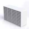
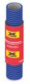
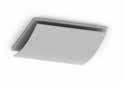
Ability to integrate stylish architectural grilles, to fit interior design scheme
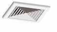
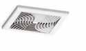
Easy Adjustment of Domus Flow Control Plenum
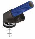
The simple plug and play mechanism between the semi-rigid duct and manifold, as well as the plenum’s clip-on fixing system, make Domus Radial ultra-quick to install. As directed in our simple online step-by-step installation guide, the only tools you will require are:
Pozidrive screwdriver
Cutting tool

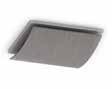
Long reach spanner* Allen key*
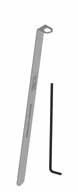
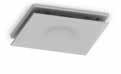
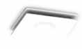
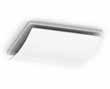
*Provided as part of architectural house packs only. Also sold as part of a kit on code FCAK1.

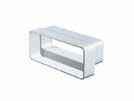
Domus Radial is available as pre-selected house packs, as well as individual parts.
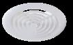 Domus Architectural Grilles
Domus Radial duct with a Flow Control Plenum, connecting to a stylish grille
Domus Radial duct with Fire Protection Sleeve
Domus Radial duct with Insulation
A Domus Radial Flow Control Plenum will allow the integration of stylish Domus grilles
Domus rigid duct 220x90mm external airbrick and adapter.
Domus Architectural Grilles
Domus Radial duct with a Flow Control Plenum, connecting to a stylish grille
Domus Radial duct with Fire Protection Sleeve
Domus Radial duct with Insulation
A Domus Radial Flow Control Plenum will allow the integration of stylish Domus grilles
Domus rigid duct 220x90mm external airbrick and adapter.
Parts that may be needed to make up a Domus Radial system.
Property configurations vary, which is why the flexibility of our Radial system is so useful. A 50m coil that negates the need for multiple bends resulting in reduced system resistance, and can be cut to length at your convenience. For FREE layout and technical advice email: vent.projects@domusventilation.co.uk
Type Code
Radial Semi-Rigid Duct and Clips
Description
RDD75 Semi-Rigid Duct, Ø75mm - 50m Coil
RDD7590 Semi-Rigid 90 degree duct connector 75mm


RDC75 Semi-Rigid duct connector 75mm

RDCLIP75 Duct Clips, Ø75mm – Pack of 10

RDPC75 Manifold Protective Caps
Radial Manifolds and Domus Adapts

RDM-EP150 Manifold (Round)
RDM-MD220 Manifold (Rectangular)
RDLAB Manifold Extract and Supply Label Kits
RDA-3FA Adapt 204x60mm In-Line Adapter 3xØ75mm Radial Sockets, Female adapter
RDA-3FC Adapt 220x90mm In-Line Adapter 3xØ75mm Radial Sockets, Duct only
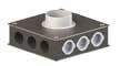
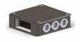
Type Code Description
Radial Manifolds and Domus Adapts
RDA-3FV90 Adapt 220x90mm Vertical 90° Bend 3xØ75mm Radial Sockets
RDA-3FH90 Adapt 220x90mm Horizontal 90° Bend 3xØ75mm Radial Sockets


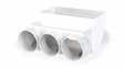
Radial Semi-Rigid Duct Components
RDA-3R90-125 Adapt Ø125mm Plenum 3xØ75mm Radial Sockets
RDA-3R90-150 Adapt Ø150mm Plenum 3xØ75mm Radial Sockets
RDA-3T Adapt 220x90mm T Piece 3xØ75mm Radial Sockets
RDA-6T Adapt 220x90mm T Piece 6xØ75mm Radial Sockets
RDA-6TB Adapt 220x90mm T Piece 3xØ75mm Radial Sockets 3 from Branch
RDA-CSK3 Adapt Spares
2 Blanking Caps, 3 Clips and 3 Seals
RDA-CSK6 Adapt Spares
4 Blanking Caps, 6 Clips and 6 Seals
RDS75 Rubber seals x10

Radial Semi-Rigid Duct Fire Solutions
RDA-FSK Adapt Fire Sleeve
RDFS75 Semi-Rigid Duct Fire-Stopping Sleeve
Plenums and Internal Terminals
RDOP-125 Plenum, Ø125mm for Air Value or RDOP-125FC OR Flow Control Plenum, Ø125mm For Architectural Grilles
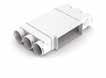
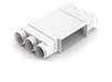

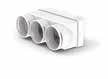
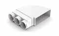

RDI-25X5M Insulation for Ø75mm Semi-Rigid Duct
RDD125 Insulated Rigid Duct, Ø125mm - 1m
RDD12545 Insulated Rigid Duct 45 Degree Bend 125mm

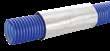
RDD12590 Insulated Rigid Duct 90° Degree Bend, Ø125mm


RDD150 Insulated Rigid Duct, Ø150mm - 1m
RDD15090 Insulated Rigid Duct 90° Degree Bend, Ø150mm
For more information on Domus Adapt, see page 132-136.
Domus Adapt is a unique duct solution, which will allow for simple, straightforward connection between PCDB (Product Characteristics Database) listed Domus Radial semi-rigid and Domus rigid duct systems with minimal effort.
Designed to lower project costs, whilst also reducing duct installation time by up to 25%; Domus Adapt has innovatively evolved Radial semirigid duct systems, to make installing whole house ventilation, EASIER and MORE COST EFFECTIVE than ever before.
Lowers project costs
Simplifies installation, to overcome site constraints and space restrictions
Reduces installation time
Allows for a variety of duct configurations
Ideal for apartments or cluster developments, such as care homes and student accommodation*
Allows installers to run straight into Domus Radial semi-rigid Ø75mm duct; no need for tape, screws or sealant
Provides a complete ducting solution, including the ducting for supply and extract when supporting a kitchen plus two wet rooms
Will remove the need for a manifold; lowering installation costs and time
Helps prevent complicated duct runs, providing simpler design and installation
A versatile solution to help overcome issues associated with a lack of installation space or tight void areas
Domus Radial is a simple plug-and-play, labour saving duct system, which takes away the need for traditional jointing
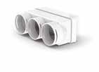
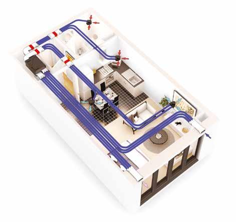
Manufactured in the UK
*Capable of achieving up to 30l/s per fitting.
The Domus Adapt range includes T-pieces, In-line Adapters, Elbows and Bends, available to install with a MVHR or MEV appliance. All pressure loss figures have been tested by the Building Research Establishment (BRE).
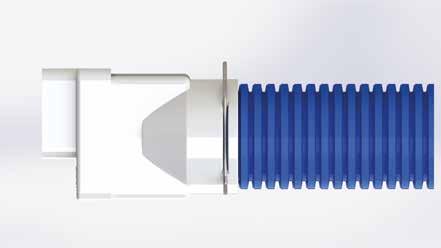
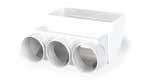
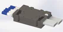
Domus Adapt can be seamlessly installed with the HRX Mechanical Ventilation with Heat Recovery range, allowing fitters to ADAPT straight into Domus Radial duct, thus removing the need for expensive manifolds. All units are available with a Bluebrain Controller, for enhanced user control and air comfort.
HRX-aQ
Ideal for ceiling/void applications in a floor area up to 80m². For more information on unit, see page 29.
HRX2D
For installation in a floor area up to 250m². For more information on unit, see page 25
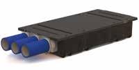
The Domus Adapt range includes T pieces, In-line Adapters, Elbows and Bends, available to install with a MVHR or MEV appliance. All pressure loss figures have been tested by the Building Research Establishment (BRE).
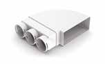
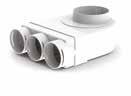

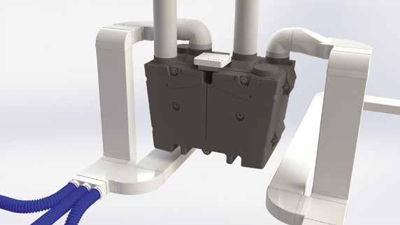
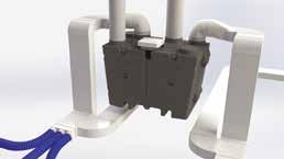
Adapt T Pieces
As a versatile solution, the CMX Mechanical Extract (MEV) appliance is available with Domus Adapt, for a straight in and out Radial duct run.
Code: CMXR-S
Socket Size: 220x90mm
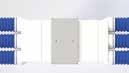

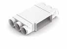
Radial Duct Socket Size: Ø75mm
Includes: CMX-S MEV unit, 1 blanking cap, 3 seals and 3 clips
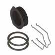
RDA-3T, 220x90mm
RDA-6T, 220x90mm RDA-6TB, 220x90mm
RDA-3FA, 204x60mm RDA-3FC, 220x90mm
RDA-3R90-125, Ø125mm RDA-3R90-150, Ø150mm
RDA-3FV90, 220x90mm
RDA-3FH90, 220x90mm
Three T-Pieces available in the range which seamlessly incorporate 220x90mm rigid duct and Ø75mm Radial from a centralised mechanical ventilation unit.
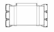
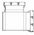
Connect into 6 x Ø75mm Domus Radial duct runs.
Code: RDA-6T
T Piece Socket Size: 220x90mm
Radial Duct Socket Size: Ø75mm
Connect into 6 x Ø75mm Domus Radial duct runs.
Code: RDA-6TB
T Piece Socket Size: 220x90mm
Radial Duct Socket Size: Ø75mm
Connect into 3 x Ø75mm Domus Radial duct runs.
Code: RDA-3T
T Piece Socket Size: 220x90mm
Radial Duct Socket Size: Ø75mm
Includes: 4 blanking caps, 6 clips and 6 seals
Includes: 4 blanking caps, 6 clips and 6 seals Figures represent a 50%
duct.
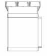
This range offers adapters which convert a system’s duct from standard uPVC to Domus Ventilation Radial.
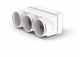
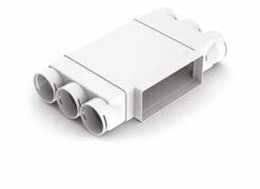
Option 1
Connect into 3 x Ø75mm Domus Radial duct runs.
Code: RDA-3FA
In-line Socket Size: 204x60mm
Radial Duct Socket Size: Ø75mm
Includes: 2 blanking caps, 3 clips and 3 seals
Option 2
Includes: 2 blanking caps, 3 clips and 3 seals
Connect into 3 x Ø75mm Domus Radial duct runs.
Code: RDA-3FC
In-line Socket Size: 220x90mm
Radial Duct Socket Size: Ø75mm
Includes: 2 blanking caps, 3 clips and 3 seals
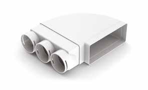
The plenum, also known as an ‘elbow bend’ integrates Ø150mm rigid duct with Ø75mm Domus Ventilation Radial in one, straight forward connection with minimal effort. All pressure loss figures have been tested by the Building Research Establishment (BRE).
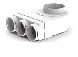
Connect into 3 x Ø75mm Domus Radial duct runs.
Elbow Spigot Size: Ø125mm
Radial Duct Socket Size: Ø75mm
Includes: 2 blanking caps, 3 clips and 3 seals
Connect into 3 x Ø75mm Domus Radial duct runs.
Elbow Spigot Size: Ø150mm
Radial Duct Socket Size: Ø75mm
Includes: 2 blanking caps, 3 clips and 3 seals
The RDA-3FH90 combines 220x90mm PVC and Ø75mm Radial at a 90 horizontal bend.
Connect into 3 x Ø75mm Domus Radial duct runs.
Code: RDA-3FH90
Bend Socket Size: 220x90mm
Radial Duct Socket Size: Ø75mm
Includes: 2 blanking caps, 3 clips and 3 seals
With 3xØ75mm Radial Sockets
The RDA-3FV90 combines 220x90mm PVC and Ø75mm Radial at a 90 vertical bend.
Connect into 3 x Ø75mm Domus Radial duct runs.
Code: RDA-3FV90
Bend Socket Size: 220x90mm

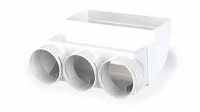
Radial Duct Socket Size: Ø75mm
Includes: 2 blanking caps, 3 clips and 3 seals

Blanking Plates, Clips and Seals
Whilst ‘House Packs’ are available, which provides an estimated system requirement for average plots, Domus Ventilation also offer Spares Packs which ensure you have enough fixings on-site, at a minimal cost.
Option 1
Code: RDA-CSK3
Includes: 2 blanking caps, 3 clips and 3 seals
Option 2
Code: RDA-CSK6
Includes: 4 blanking caps, 6 clips and 6 seals
The RDA-FSK is a Fire Sleeve designed specifically for use with the Adapt range and exceeds all Fire Regulations needed for both new-build and refurb projects. It is quick and easy to install. Please contact us for availability of other sizes.
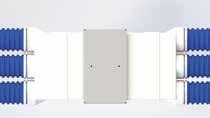
Code: RDA-FSK
Size: 204x60mm
Domus Ventilation flexible and semi-rigid duct is available in all standard UK round and rectangular sizes. The range includes Hose, Insulated Hose and Aluminium Hose.
Domus Ventilation Flexible Hose is a range of wire reinforced, flexible PVC ducting that has been specially designed for the ventilation market. The round profiles are compatible with the Domus Ventilation rigid PVC product range.
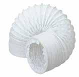
The hose provides solutions to overcome situations where a rigid component cannot be installed. Flexible hose is particularly suitable for installation where there is slow moving air, such as, the ducting of tumble driers. Construction
The Flexible Hose is constructed as a continuous left-hand helix (English wound) on a bespoke forming ‘head’. The reinforcing wire is 100% sealed inside a fold of PVC tape which is in turn overlapped by the next pitch. The joints are welded by hot air welding of the layers of PVC in order to produce a continuous sealed tube.
Material
Max.
Packing
Clamping
Compressed individually in net sleeve
Domus Adjustable Round Hose Clip
100mm – 125-4
125mm – 125-5
150mm – 125-6
The Aluminium Flexible Hose is a range of fully flexible uninsulated aluminium/ polyester laminated ducting, which has been specially designed for Domus Ventilation. Owing to its flexibility it is easy to connect to either round or oval ducting.
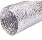
Aluminium/Polyester Flexible Hose – 3m - 10m Technical data
Supplied in standard 10 metre length, compressed to 0.6 metre
Individually boxed
Easy to connect to either round or oval ducting
No special tools required for cutting or fixing
In the event of a fire, no toxic gases are emitted
Construction material Reinforced Aluminium/Polyester
Wirepitch 24mm
Diameter range (mm) 100 / 125 / 150
Temperature range (°C) -30/+140
Maximum air velocity 30m/sec
Max. positive working pressure 2500 Pa
Standard length 10 metre
Packing
Individual box of 0.6 metre
The products have been successfully fire resistance tested to BS476 parts 6, 7 and 20 Construction
Clamping
Lightning Band, Stainless Steel Clamps, Nylon Clamps or Quick Release Clamps
The Domus Ventilation Aluminium Flexible Hose is multi-ply reinforced aluminium and polyester laminated ducting with an encapsulated high tensile steel wire helix.
Aluminium
Domus Ventilation Insulated
Flexible Hose is a range of fully thermally insulated ducting, which has been specially designed for the ventilation market. It has been developed to minimise heat gain or loss resulting from the temperature differential between the airflow and the surrounding ambient air. The vapour barrier prevents condensation from forming on the outside of ducts carrying air at lower temperatures than the surrounding air.
Supplied in standard 10 metre length, compressed to 1 metre
u Individually boxed
u Easy to connect to either round or oval ducting
u No special tools required for cutting or fixing
u In the event of a fire, no toxic gases are emitted
u The products have been successfully tested for fire resistance and conform to BS476 Parts 6 and 7
Diameter range (mm) ww(internal) 100, 125, 150
Temperature range (°C) -30/+150
Maximum air velocity 30 m/sec
Max. positive working pressure 3000 Pa
Standard length
Packing
Clamping
10 metre
Individual box compressed to 1m
Domus Ventilation Adjustable Round Hose Clip
100mm – 125-4
125mm – 125-5
150mm – 125-6
Domus Ventilation Insulated Flexible is produced from multi-layer aluminium and metallised polyester, strengthened with high tension hard steel spring wire, surrounded with glass wool insulation and an aluminium vapour barrier.
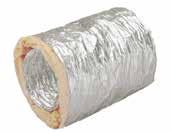
For years the designer’s need for a fire resistant flexible duct has been hampered by the lack of flexibility and fragile nature of metallic ducting. Now, Domus Ventilation Aluminium Flexible Duct overcomes these problems.
Aluminium Flexible Duct is a corrugated flexible ducting, which can be formed to bend radii less than ½D. It is supplied in its compressed state, but when installed the tube extends to 4 metres for maximum flexibility and economy – making it the simple answer to many flexible duct problems.
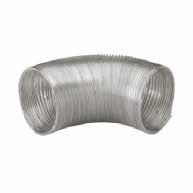
u Constant cross section for predictable air flow characteristics
u Reduced need for supports on longer duct runs
u Fire resistant to BS 476 Part 8 with negligible smoke generation
u Extra flexibility. Ideal for short final connections
u Supplied in compressed lengths and individually boxed for site protection, easy handling and storage
Flexible
It is available in 100mm, 125mm and 150mm diameter and may be hand-formed to bends of less than a 1/2D Radius- a feature previously only thought possible with fabric flexibles.
Aluminium Flexible Duct can also be extended or compressed easily for installation between spigots located opposite to each other. It is ideal for final connections or where space is limited.
Strong
Strength and pliability in metal flexibles are affected by the thickness, corrugation shape and ductility of the material used in construction. In the past a strong tube has lacked flexibility and flexible tube has lacked strength.
With Aluminium Flexible Duct the problems are overcome by producing a deep corrugation tube, which is kept in the compressed state until it is installed; in this state it has great strength with little flexibility. At the time of installation, when strength is a lower priority, the tube is extended to achieve its ultimate in flexibility.
Self supporting
Aluminium Flexible Duct retains its corrugation form in use and, in doing so, achieves maximum distance between supports without sagging, resulting in cost savings in labour and materials when compared to fabric flexible.
It also retains its cross section regardless of its state; it can be compressed, extended, or formed into bends or offsets with no reduction in area.
This means that frictional resistance figures are constant and air flow figures can be accurately predicted at the design stage.
The tube is stable after forming with no tendency to spring back, thus forces on spigots are kept to the very minimum.
Fire resisting
Aluminium Flexible Duct is tested to BS476 Part 6, 7 and 8, and meets the requirements for CP413 section A2.2.3 (Ducts for Building Services) and is suitable for use throughout the U.K. and the Continent. When tested to BS476 Part 7 a class 1 spread of flame was recorded. When tested under the conditions laid down in BS476 Part 8 Aluminium Flexible Duct maintained its integrity for 15 minutes. As it is of all metal construction smoke generation is negligible.
Aluminium Hose Clip – 100, 125 and 150mm (for installation with Domus Flexible Hose)
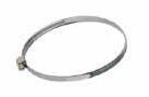
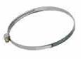
The Aluminium Duct Clips are designed to provide a secure, air-tight connection. The range also includes Universal Connectors, offering greater installation flexibility.
Aluminium Universal Hose Clip – 100, 125 and 150mm (for installation with Domus Flexible Hose)
The Aluminium Duct Clips are designed to provide a secure, air-tight connection. The range also includes Universal Connectors, offering greater installation flexibility.
Our flexible hose connectors are designed to achieve the highest possible energy efficiency from our ventilation appliances. They are manufactured from exacting tolerances to virtually eliminate air leakage and reduce pressure drop.
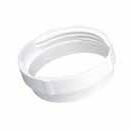
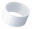
Round Flexible Hose Connectors – 0.1m
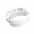
Round Flexible Hose Connectors – With Threaded Socket
Round Flexible Hose Connectors – With Threaded Spigot
Rectangular
Domus Ventilation Flexible Hose is a range of wire reinforced, flexible PVC ducting that has been specially designed for the ventilation market.
The hose provides solutions to overcome situations where a rigid component cannot be installed.
Flexible Hose is particularly suitable for installation where there is slow moving air, such as the ducting of tumble driers.
The Flexible Hose is constructed as a continuous left-hand helix (English wound) on a bespoke forming ‘head’. The reinforcing wire is 100% sealed inside a fold of PVC tape which is in turn overlapped by the next pitch. The joints are welded by hot air welding of the layers of PVC, in order to produce a continuous sealed tube.
Technical data
Material White PVC 70μm thick
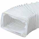
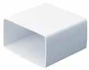
Sizes mm (internal) 110x54, 204x60, 220x90
Temperature range (°C) -20/+60 working (80 max.)
Standard length (m) 0.5, 3
Packing Compressed individually in net sleeve
Clamping
D-TIE
Nylon zip-tie
Designed to achieve the highest possible energy efficiency from our ventilation appliances.
Alongside our ventilation systems and ducting, we offer a range of ancillary items.
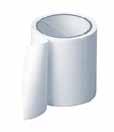
A 30 Micron soft tempered bright aluminium foil. Coated with high tack pressure adhesive which has excellent UV light resistance on a white glassine liner.
This product is recommended where a moisture barrier and cold weather performance is required.
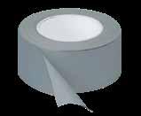
Jointing of polythene sheeting
Barrier tape to prevent electrolytic reaction
Sealing insulation panels
Patching, sealing (boxes, drums, kegs) repair
The above figures are average values and should not be regarded as maximum or minimum values for specification purpose.
The purchaser shall be responsible for determining the suitability of this purpose. Goods which prove to be defective through faulty material or workmanship must be returned to us, carriage paid. These will be replaced or credited. We shall not be liable for consequential damage incurred in the use of this material. All slitting and length tolerances are to British Standards, but other tolerances are available on request.
Technical data Typical values
Adhesive colour: Clear
Adhesive type: Acrylic UV Light resistance
Tape thickness: 0.060mm (without liner)
Foil thickness: 0.030mm
Peel adhesion to steel: 1000N/m
Loop tack: 800N/m
Shear (static): 87 Hours @ 1kg
Fire protection: Conforms to Class O BS476 part 7 & 6 1987
Minimum applic temp: 0˚C
Service range: -20˚C to 120˚C
Shelf life: 12 months (PSMA Conditions)
Technical data Typical values
Total thickness: 0.14 mm
Adhesive power: 200N/m
Backing thickness: -
Tensile strength: 2KN/m
Elongation: 200%
Temperature: -20˚C to 80˚C
Dielectric strength: 6KV
Colours: Black, White, Grey
Shelf life: 12 months

Good adhesion to timber, plasterboard, masonry, blockwork, plaster, concrete and many other common building surfaces
Up to four hours fire resistance
Over-paintable with solvent and water based paints
Water based, solvent and halogen free, water clean up Reduces sound transmission in joints
Formulated using a special acrylic emulsion to provide a firm seal whilst retaining a degree of flexibility
Joint movement capability of ±12.5%
Will not support combustion
DDSEAL conforms to the following standards:
Fire Performance
BS 476:Part 20:1987. BS EN 13666-3 with additional guidelines from BS EN 1366-4
Acoustic Performance:
Tested in accordance with BS EN ISO 140-3:1995
Code DDSEAL
DDSEAL sealant is a waterborne one-part fire-resistant and acoustic rated joint sealant which provides a firm, yet flexible, seal to joints in a wide variety of fire-rated structures where fire resistance up to four hours is required. Its special intumescent properties cause the sealant to swell up and char in the presence of heat, preventing the spread of smoke and fire through the joint.
Uses
Sealing joints, voids and irregular holes where fire resistance up to four hours is required
Ideal for sealing joints, voids and irregular holes in fire walls, partitions, door architraves, service penetrations, floors and other structures
For bedding of hinges and locks in fire doors
For perimeter sealing of internal, fire rated screens, partitions, service penetrations and door or window frames
To maintain integrity when sealing around pipes, services and cable
Sealing fire rated ductwork
Suitable for horizontal and vertical joints without compromising fire rating performance
For use in joints up to 50mm
Technical data
Colour: white
Sealant Classification ISO 11600 Classification: F-12.5-P
Typical values
Adhesion: Good adhesion when applied to wood, plaster, plasterboard, blockwork
Base technology: Acrylic emulsion
Chemical resistance: Fair to dilute acids and alkalis
Curing system: Dries through evaporation
Hardness (Shore A 25°C): 50
ISO 11600 classification: F-12.5-P
Mould resistance: Contains a fungicide
Movement accommodation: ±12.5%
Paintability: Can be overpainted.
Service life (predicted): 20 years
Service temperature range: -15°C to +70°C
Shrinkage: <25%
Specific gravity: 1.56 - 1.60g/cm3
Slump: Nil
Staining: Nil
UV resistance: Good
Volatile content: <25%
Acoustic rating: 40(-3;-8)dB Rw(C;CTtr) BS EN ISO 717-1:1997
Good adhesion to a wide variety of surfaces including PVC, timber and brickwork
Easy to apply and finish
For sealing internal joints around window and door frames, skirting boards, coving and dado rails Sealing cracks in plaster
DASEAL is a high performance emulsion acrylic sealant based on the latest developments in acrylic elastomer technology. It has been specially formulated for sealing around window frames, skirtings, architraves and general small gap filling.
It offers a degree of flexibility whilst still retaining the ability to be easily overcoated with conventional paints. Although primarily used internally, it has good external performance when applied in suitable conditions.
DASEAL is a high performance sealant which conforms to ISO 11600 - F-12.5P.

Technical data
Can be overpainted within one-two hours with both water and solvent borne paints
Quick drying – forms a skin within 15 minutes internally
Contains a high level of fungicide for long term decorative appearance
Colours: Brown & white
Perimeter pointing of windows and doors
External low to medium movement joints between brick, concrete and timber
Typical values
Note: Ensure that the conditions are suitable to allow the development of a substantial skin before exposure to rain, typically a minimum of four hours.
Adhesion: Moderate to good adhesion to timber, PVC, plasterboard and plywood
Base technology: Acrylic polymer
Chemical resistance: Fair to dilute acids and alkalis
Curing system: Evaporation
Hardness (Shore A 25°C): Approx 50
Mould resistance: Contains a fungicide
Movement accommodation: ±12.5%
Paintability: Easily overpainted
Service life (predicted): 15 years
Service temperature range: +5°C to +30°C
Shrinkage: < 20%
Specific gravity: 1.62 to 1.66 g/cm3
Slump: Nil: (up to 20mm x 10mm vertical channel)
Staining: Nil
UV resistance: Good
Volatile content: < 20%

Did you know, in addition to our extensive range of products, Domus Ventilation also offer a range of accredited courses designed for individuals working in the ventilation industry.
Courses aim to increase individuals’ skills and knowledge, including the ventilation requirements of the latest Building Regulations and, as a recognised course, you can earn CDP credits.
CPD Accredited courses available include:
Residential Ventilation Principles & Building Regulations
Pre-Planning Conditions & Ventilation
MVHR Design & Best Practise
For further information and to book your place, email Sinead Morris at: sinead.morris@domusventilation.co.uk

Building Information Modelling (BIM) is a software application to design, construct and manage buildings within the construction industry.
Features include:
Manages the design work-in-progress and speeds reviews and approvals
Produces high-quality designs faster
Improves onsite collaboration and communication

Visualises projects in pre-construction
Mitigates risks and reduces costs
Improved scheduling and sequencing
Download directly from the Domus Ventilation website for FREE
Increases productivity with prefabrication
Streamlines facility management and strengthens building handovers
Optimise project performance with the FREE Domus Ventilation family manager FREE Domus Ventilation family manager