OPERATION AND MAINTENANCE MANUAL
MOBILE WELFARE - DEEP GREEN
ENGINEERED BY BOSS CABINS
DEEP GREEN FULL SP E C TR UM SU S TAINABILI T Y 203 0
Operation & Maintenance Manual CONTENTS 1. Introduction 4 1.1 Introduction 5 1.2 General Safety 6 2. Know Your Unit 7 2.1 Technical Diagrams and Guides 8 2.2 Masses and Dimensions 10 3A. Transporting The Cabin - 12ft & 16ft Units 11 3A.1 Preparing the Unit for Towing - 12ft & 16ft Units 12 3A.2A Attaching Unit to Towing Vehicle - Ball Hitch 13 3A.2B Attaching Unit to Towing Vehicle - Pin & Eye 13 3A.3A Uncoupling the Unit - Ball Hitch 14 3A.3B Uncoupling the Unit - Pin & Eye 14 3A.4 Deploying the Unit 15 3A.5 Anti-Vandal Cover - Flap or Cowl 16 3A.6 Using the Low Level Lifting Eyes 16 3B. Transporting The Cabin - 20ft & 24ft Units 17 3B.1 Preparing the Unit for Towing - 20ft & 24ft Units 18 3B.2A Attaching Unit to Towing Vehicle - Ball Hitch 19 3B.2B Attaching Unit to Towing Vehicle - Pin & Eye 19 3B.3A Uncoupling the Unit - Ball Hitch 20 3B.3B Uncoupling the Unit - Pin & Eye 20 3B.4 Deploying the Unit 21 3B.5 Anti-Vandal Cover - Flap or Cowl 22 3B.6 Using the Low Level Lifting Eyes 22 4. Powering The Unit 23 4 Powering the Deep Green Unit 24 4.1 Using an External Power Source 24 4.2 Using the Internal SolarFlowTM Hybrid Power System 26 4.3 Generator Checks Before Use 26 4.4 Turning On the Electrical System 28 4.5 Leaving the Cabin 28 5. Electrical System & Equipment 29 5. Using The Electrical System 30 5.1 Hibernation Isolator Switch 30 5.2 Internal/External Power 30 5.3 Using the Electrical Equipment 31 5.4 Using the Heater 33 5.5 Electrical Installations 33 6. Inside Your Welfare Unit 35 6.1 Drinking Water 36 6.2 Fresh Water Tank 36 6.3 Waste Water Tank - Canteen 36 6.4 Waste Water Tank - Toilets 37 6.5 Dispensers 37 6.6 Food Preparation 37 6.7 Carbon Monoxide Alarm 37 6.8 Bench Seating 38 6.9 Windows And Shutters 38 6.10 Magnetic Door Stays 38 6.11 Door Locks 38 2
Operation & Maintenance Manual CONTENTS 7. Using Your Fresh Water System - Rain Harvesting & Water Recycling 39 7. Using Your Fresh Water System 40 7.1 Rain Harvesting 40 7.2 Water Sterilistaion 41 7.3 Fresh Water Tank 42 7.4 Grey Water Recycling 42 7.5 Waste Tank and Disposal 43 7.6 Toilet 43 7.7 Hand Wash Basin 43 7.8 Handryers 44 7.9 Soap Dispenser 44 7.10 Toilet Door Locks 44 8. Maintenance 45 8.1A Changing a Wheel - Single Axle 12ft & 16ft 46 8.1B Changing a Wheel - Double Axle 20ft & 24ft 47 8.2 Brake Setting Procedure – Preparation 49 8.2A Brake Setting Procedure – Single Axle 50 8.2B Brake Setting Procedure – Double Axle 51 8.3 Brake Check and Test 53 8.4 Service Checks 54 8.5 Electrical Checks 55 8.5.1 Fuse Box Check 55 9. Diagnostics 56 9. Diagnostics – Deep Green 57 9.1 No Electricity In Cabin 58 9.2 Generator Issues 60 9.3 No 230V Power To Cabin 62 9.4 No 24V Power In Cabin 64 9.5 Electric Hydraulic System Not Working – No Power To Rams 64 9.6 Water Heater Not Working 65 9.7 Heater Not Working 66 9.8 Water Tank Not Filling With Rain Water 67 9.9 Battery Not Being Charged By Solar Panels 68 10. Warranties 69 10.1 Manufacturer Warranty – 12 Months 70 10.2 Anti-Corrosion Warranty - 25 Years 70 10.3 Generator Servicing & Warranty 71 10.4 Extended Generator Engine and Alternator Warranty - 5 Years 71 10.5 SOLARTrackTM Parts Warranty 71 11. Towing Advice & Legal Obligations 72 11.1 Legal Obligations – Cabin and Towing Vehicle 73 11.2 Legal Obligations – Towing Vehicle Driver 76 11.3 Driving Advice 80 12. Other Information 82 12.1 Safety Decals 83 13. Legal Requirements – Mobile Welfare 84 13.1 Onsite Welfare Provision – Construction (Design And Management) Regulations 2015 85 13.2 Roadworthiness – VCA Type Approval Under Directive 2007/46/ec 86 13.3 Electric Installations – Bs7671 Iet Wiring Regulations 18th Edition 86 3
1 INTRODUCTION
1.1 INTRODUCTION
THANK YOU FOR CHOOSING THIS BOSS CABINS DEEP GREEN UNIT.
To avoid personal injury or equipment damage, carefully read these instructions and ensure you understand them before using this equipment.
The information and instructions included in this manual are provided to help you get the best possible service from your welfare unit. To ensure that the unit is used safely and responsibly, we strongly recommend that this manual is read by all users prior to its operation, and that the recommendations are followed at all times. It is the responsibility of the operator to read and understand the contents of this manual before operating the vehicle for the first time.
If there is anything you do not understand, DO NOT use this equipment, and contact your supplier for advice. Ensure everyone responsible is fully conversant with the procedure for attaching the towing vehicle, towing, loading, setting up, removing, operating and maintaining the unit.
Certain information in this manual is governed by law and is subject to change without prior notice. Great care has been taken to ensure that the information is correct at the time of publication. However, it is the user’s sole responsibility to ensure that they fully comply with all legal requirements. Boss Cabins will not accept liability for any inaccuracy or incorrectly stated legal requirement.
Regular inspection, servicing and periodic maintenance will ensure trouble free operation.
Boss Cabins operates a policy of continuous improvement and reserve the right to change specifications without notice. The most current version of this manual will always be available on request by telephone or email.
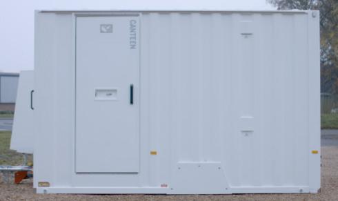
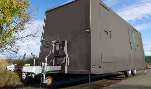
Deep Green mobile welfare cabins are road towable units with full VCA approval.
Depending on the model, these self-contained units may be equipped with a kitchen/restroom, an office, a drying room and one or two toilet cubicles.
Electrical supply can be taken either from mains hook up or from a Lithium Ion battery which is charged by solar panels on the roof. A back-up generator supplies power to charge the battery if there is not enough solar energy being generated.
The unique design means that raising and lowering the body requires little effort from the operator and takes under one minute from disconnecting from the towing vehicle to being fully operational.
Operation & Maintenance Manual
1 – Introduction 5
1.2 GENERAL SAFETY
SAFETY IS EVERYONE’S RESPONSIBILITY
Before using this equipment and to avoid personal injury, carefully read and understand these instructions. If there is anything you do not understand, DO NOT use this equipment, contact the supplier for advice.
Make sure you are aware of all the safety requirements and that this equipment is suitable for the location. When manoeuvring the unit into position, if working on a public road or in a public accessible space use the high intensity warning beacons fitted to the towing vehicle or its hazard warning lamps to raise awareness of its movement. If visibility is limited use a banksman or other assistance to guide you.
When raising or lowering the unit, the area must be cordoned off to create a safe zone, isolating the unit from the general public and bystanders.
This equipment must not be moved, set up, used or dismantled by persons who are under the influence of alcohol or drugs. Do not use this equipment if you are tired or unwell. The equipment must not be operated, moved or used by any person not deemed competent to do so. You MUST perform a risk assessment before siting this equipment to ensure your safety and the safety of others. Wear suitable personal protective equipment whenever making adjustments to the unit.
Do not wear loose jewellery or clothing that may get in the way or become trapped in the mechanism. Carefully inspect the unit before towing or before use.
If there is any doubt about its condition, DO NOT CONTINUE
This equipment may only be used on smooth level ground, which is able to bear its weight and its load.
RISK ASSESSMENT
It is the user’s responsibility to carry out a full risk assessment before siting the unit, to establish a safe zone including (but not limited to):
GROUND HAZARDS
Ensure suitable smooth level ground capable of bearing the mass of the unit plus occupants etc. in all weather conditions and check proximity to underground services. If permission is required, obtain it before use.
SIDE HAZARDS
Proximity to other buildings, trenches and equipment, clearances for exhaust outlet and ventilation and light where required.
OVERHEAD HAZARDS
Proximity to power supply and communication cables, lighting systems, drainage systems and other services.
PREPARATION FOR TOWING
Before towing the unit, it is essential that:
- All loose items are stowed.
- Additional items are removed from the cabin. Do not use the cabin as a payload trailer. Additonal items may cause the unit to be overweight.
- 12ft, 20ft and 24ft units are designed to be safe to tow with a full fresh water tank. The water tank of the 16ft cabin must be emptied before towing.
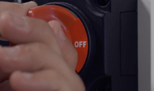
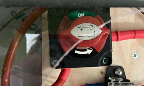
- The Hibernation Switch must be in the OFF position to completely isolate all electrics and make sure the external PIR-sensor lights do not activate while on the road causing a hazard.
- Toilet waste tanks must be emptied before towing.
- Empty the Waste tank and Drinking Water tank in the Canteen.
- Lock all doors, windows and shutters.
WORK AREA PREPARATION
Survey the ground area where the unit is to be used, clear it of obstructions, anything that may puncture the tyres and similar items. Once the unit is in the work area, use barriers, signs and tape to create a safe zone. Keep bystanders and unauthorised persons away when setting the unit up.
Operation & Maintenance Manual
1 – Introduction
Before carrying out any electrical repair work in this cabin, you must isolate the generator and battery supplies by turning the Cabin Hibernation Switch OFF. 6
WARNING
KNOW YOUR UNIT 2
2.1 TECHNICAL DIAGRAMS AND GUIDES
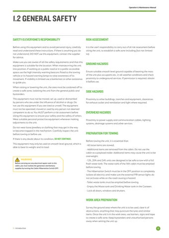
Here we give a guide to the most important external elements of your Deep Green mobile welfare unit.
See next page for descriptions.
Operation & Maintenance Manual
2 – Know Your Unit 7 8 9 10 11 12 13 14 15 16 17 18 19 20 21 6 1 4 2 3 5 22 23 24 25 26 27 28 29 30 31 32 8
Operation & Maintenance Manual
TECHNICAL
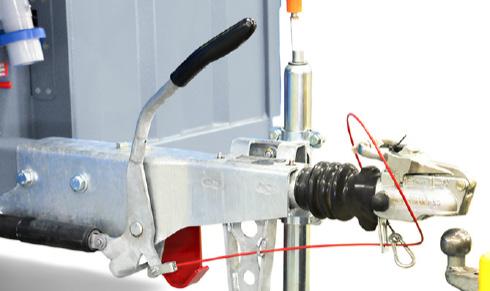
2 – Know Your Unit Item No Description 1 Roof-mounted solar panels 2 Channel for rain water harvesting with sieve outlet 3 Generator exhaust outlet 4 Generator cooling air outlet 5 Generator door panel 6 Parking brake 7 50mm standard ball coupler with inertia overrun brake actuator or pin and eye coupler if requested 8 Break away activation cable* 9 Jockey wheel 10 Road lighting connection socket 11 Protective anti vandal cover – flap 12 Front side marker lamps / reflectors * 13 Canteen entrance door 14 Antenna for SOLARTrack remote montioring system 15 Fresh water tank filler cap 16 Drying room door (24ft only) 17 External fuel gauge (in 12ft, 16ft and 20ft cabins this is located in fuel compartment on front of cabin) 18 Fuel filler cap (in 12ft, 16ft and 20ft cabins this is located in fuel compartment on front of cabin) 19 Office door (20ft and 24ft only) 20 Side marker reflectors / lights * 21 End outline marker lamps * 22 Hydraulic lift cylinders (rams) 23 Combination stop / tail / direction indicator lamps * 24 Number plate position * 25 Toilet and/or drying/changing room access doors 26 Stainless steel anti-wear corner protection 27 Window / security shutter 28 Axle release bolts (on 12ft and 16ft cabins, the axle bolt is located under the anti-vandal cover on front of unit) 29 Detachable wheel arch 30 Low-level lifting points 31 Generator cooling air inlet 32 Stainless steel anti-wear corner protection Cabin Size Axle Capacity (Kg) Tyre Size Load Rating Tyre Pressure (psi) Rim Size 12ft & 16ft 1 x 2500 215/75 R16 113 70 5.5J x 16 20ft & 24ft 2 x 1800 185/70 R13 108 87 6.0 x 13
2.1
DIAGRAMS AND GUIDES
vehicle if these items are not fitted and working. NOTE 9
It is an offence to tow the
2.2 MASSES AND DIMENSIONS DEEP GREEN
Here’s a guide to the masses, dimensions and capacities of the Deep Green 12, 16, 20 & 24 welfare cabins.
Operation & Maintenance Manual
Model Dimensions (mm) Max Mass (kg) A B C D E Deep Green 12 2900 2630 2300 4775 3650 2211 Deep Green 16 2900 2630 2300 5970 4850 2600 Deep Green 20 2900 2630 2300 7502 6060 2875 Deep Green 24 2900 2630 2300 8364 6988 3200 Tank Capacities (litres) Model Drinking Water (Canteen) Waste (Canteen) Fresh Water (Main) Waste (Main) Fuel Deep Green 12 20 25 121 (single), 159 (twin) 130 (single), 209 (twin) 56 Deep Green 16 20 25 121 (single), 159 (twin) 130 (single), 209 (twin) 56 Deep Green 20 20 25 248 (single or twin) 255 (single), 327 (twin) 56 Deep Green 24 20 25 248 (single or twin) 255 (single), 327 (twin) 43 E D A B C 2 – Know Your Unit 10
TRANSPORTING THE CABIN
12FT & 16FT UNITS 3A
3A.1 PREPARING THE UNIT FOR TOWING12FT & 16FT UNITS
IMPORTANT
Before towing, the following steps must be followed:
• All loose items must be stowed prior to towing.
• The 12ft unit is designed to be safe to tow with a full fresh water tank. The fresh water tank of the 16ft unit must be emptied before towing.
• Lock all doors, windows and close and lock the security shutters.
• The Hibernation Switch must be in
the OFF position to make sure the external PIR-sensor lights do not activate while on the road causing a hazard.
Toilet waste tanks must be emptied before towing. Empty Waste tank and Drinking Water tank in the Canteen.
• Ensure all umbilical connections are safely disconnected.
• The GVW of the towing vehicle must be no more than 18,000 kg.
CAUTION: The welfare unit is not designed as a payload trailer. Any additional items or material carried in the trailer may exceed its maximum mass. It is the driver’s responsibility to ensure this is not the case.
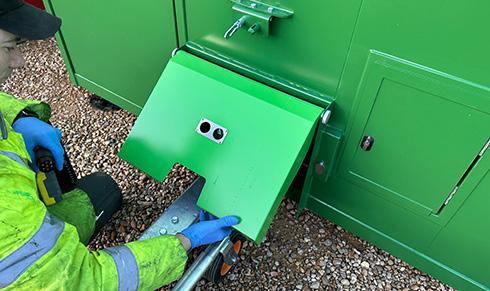
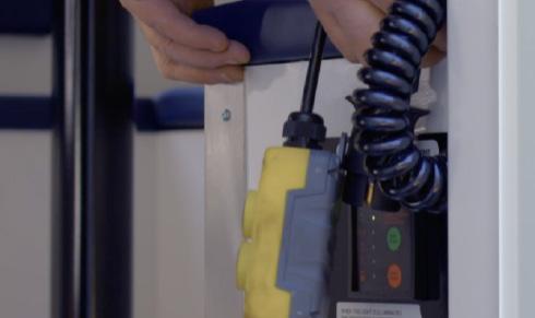
3. To prepare for towing, first unlock the anti-vandal cover using the key [1]. Remove the key and close the lock seal to prevent water or dirt entry while towing.
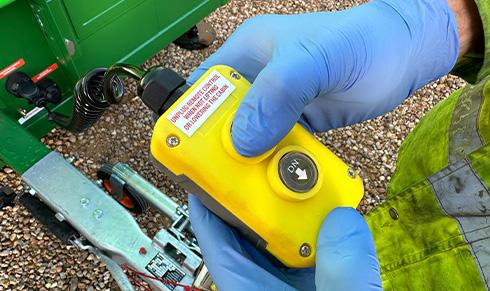
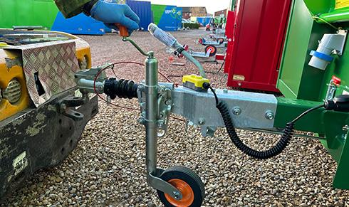
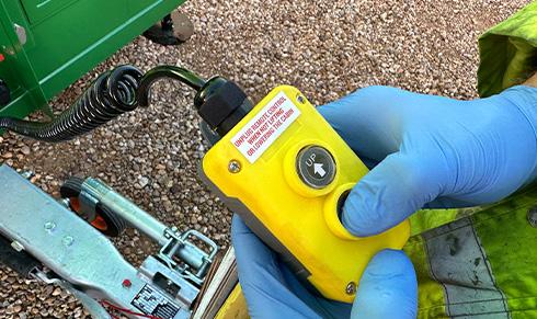
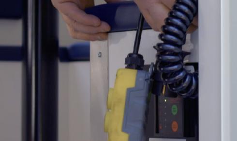
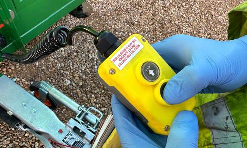
7. Remove the remote control from its storage position inside the cabin and connect the remote control’s 7 pin plug to the correct socket on the front of the unit.
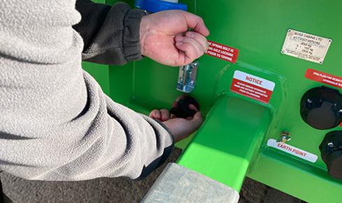
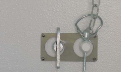
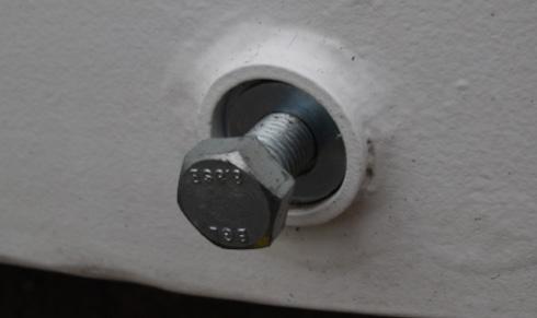
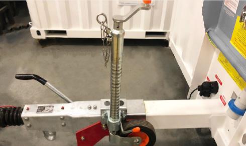
11. Lift the spring bolt into the open position, then push in handle to engage the axle locking mechanism. Then release the spring bolt making sure it covers the washer, to stop the axle locking rod from moving forward.
CAUTION
4. Raise the anti-vandal cover into the open position then engage the anti-loose fastener and the safety pin to ensure the cover stays in the towing position when on the road.
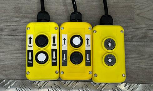
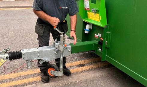
8. Depending on when your cabin was built, you may have one of three types of remote control. On all types, press the button furthest from the remote wire to lower the ram cylinders and raise the cabin.
12. Ensure there are no obstructions beneath the unit. Press the button closest to the pendant wire to retract the rams and lower the unit onto the road wheels and jockey wheel. Make sure rams are fully retracted.
The remote control pendant for the hydraulic rams must ALWAYS be disconnected from the socket when not being used.
1. Before towing, the waste tank must be emptied by a professional company. The cap is found in the toilet floor.
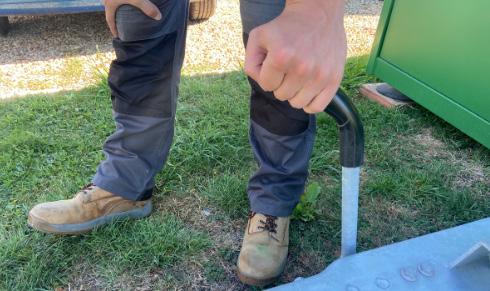
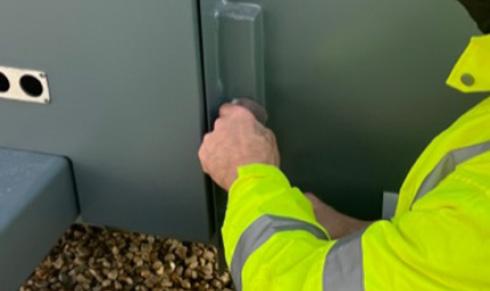
5. Raise the parking brake lever to engage the brake.
9. Keep pressing until the cabin is fully raised and the wheels are clear of the ground.
13. Always unplug the remote control unit after use and stow it safely inside the cabin. Turn the Hibernation Switch to the OFF position.
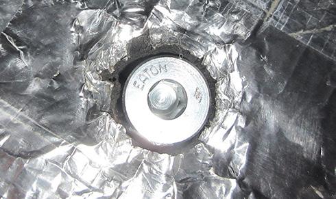
2. In a 16ft cabin, you must empty the fresh water tank before towing. The drain is under the cabin. Unscrew drain nut and allow all water to drain out before replacing and tightening the drain nut.
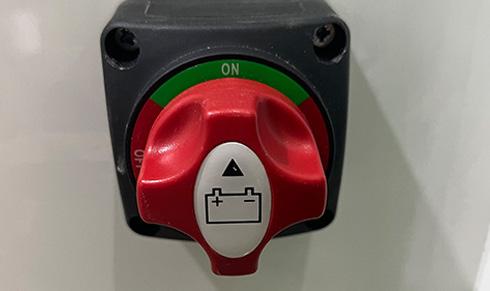
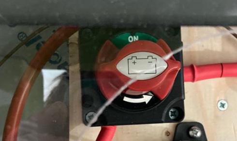
6. Locate the red Hibernation Switch in the exterior wall of the bench near door. Rotate to the ON position to turn cabin electrics on.
2
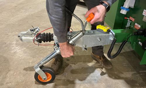
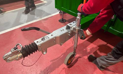
10. Pull jockey wheel release handle [2] and rotate jockey wheel assembly 90º until the wheel is lowered and the jockey assembly is perpendicular to the floor.
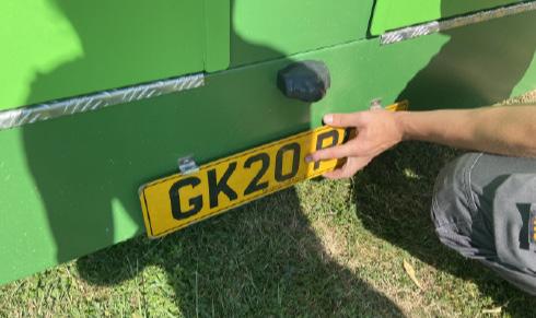
14. Insert the numberplate of the towing vehicle into the numberplate holder clip.
You are now ready to couple your unit to the towing vehicle.
CAUTION
Before towing, the Hibernation Switch must be in the OFF position to completely isolate all electrics and make sure the external PIR-sensor lights do not activate while on the road causing a hazard to other drivers.
Operation & Maintenance Manual
3A – Transporting The Cabin - 12ft and 16ft Units
1
12
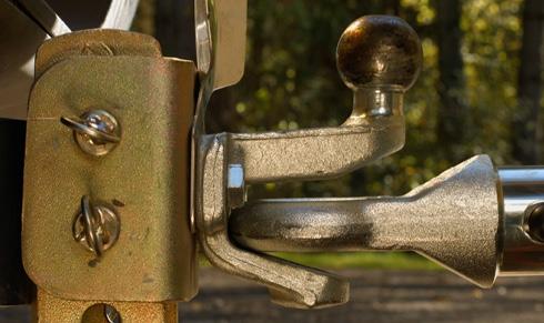
3A.2A ATTACHING UNIT TO TOWING VEHICLEBALL HITCH
1. To attach your cabin to a towing vehicle it should be in a raised position with wheels on the floor and rams raised. With the unit positioned on level ground apply the parking brake by raising the lever.
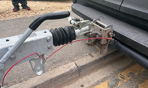
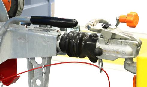
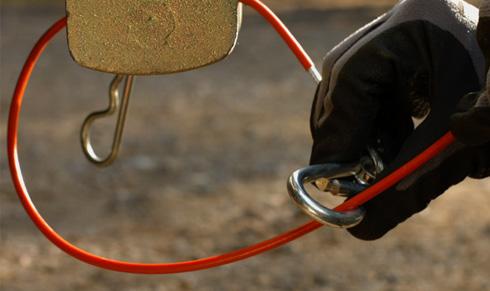
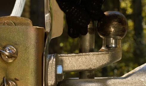
5. Attach the breakaway cable [3] to the tow hitch of the towing vehicle and ensure it is safe and operational.
2. Turn the jockey wheel operating handle [1] anti-clockwise to raise the coupling head higher than the towing vehicle’s tow ball. Then manoeuvre the towing vehicle so the ball is beneath the ball coupler.
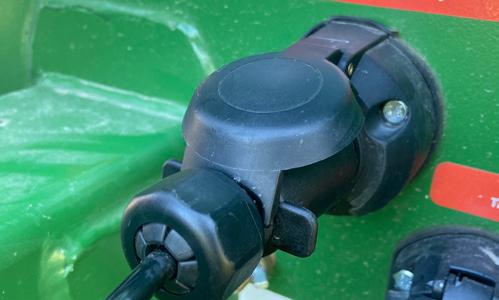
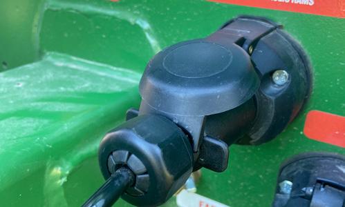
6. Connect the lighting cable plug to the socket of the towing vehicle and ensure all lights are functioning correctly.
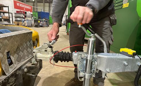
3. Raise and hold the coupling head handle [2] in the up position, and then turn the jockey wheel clockwise to lower the coupling onto the tow ball.
7. Turn orange jockey wheel handle clockwise to raise wheel clear of the ground. Pull jockey wheel release handle [4] to release and rotate jockey wheel assembly 90º until it is raised parallel to the tow bar.
4. When almost fully lowered let go of the coupling head handle and allow it to snap closed over the tow ball. Check that the coupling head is fully engaged on the tow ball.
8. Release the unit’s parking brake before towing by lowering the lever. Your unit is now attached and ready to be towed.
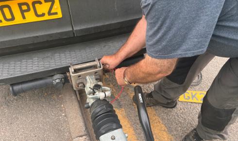
3A.2B ATTACHING UNIT TO TOWING VEHICLEPIN & EYE
1. To attach your cabin to a towing vehicle it should be in a raised position with wheels on the floor and rams raised. With the unit positioned on level ground apply the parking brake by raising the lever.
2. Turn the orange jockey wheel handle to adjust the eye to the right height then manoeuvre the towing vehicle so the eye is aligned with the pin holes on the vehicle tow bar.
3. Insert coupling pin.
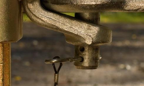
4. Secure with the safety clip [1]
7. Turn orange jockey wheel handle clockwise to raise wheel clear of the ground. Pull jockey wheel release handle [2] to release and rotate jockey wheel assembly 90º until it is raised parallel to the tow bar.
Your unit is now attached and ready to be towed.
Operation & Maintenance Manual
6. Connect the lighting cable plug to the socket of the towing vehicle and ensure all lights are functioning correctly.
5. Attach the breakaway cable to the tow hitch of the towing vehicle and ensure it is safe and operational.
8. Release the unit’s parking brake before towing by lowering the lever.
1 1
3
2 4 2 13
3A – Transporting The Cabin - 12ft and 16ft Units
3A.3A UNCOUPLING THE UNIT - BALL HITCH
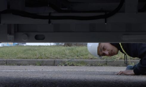
1. Make sure your cabin is situated on firm level ground able to support the weight of the unit. Inspect the ground underneath the unit and check there are no items which may damage the underside of the unit.
5. Detach the breakaway cable from the tow hitch of the towing vehicle.
2. To uncouple the unit from the towing vehicle, first apply the parking brake.

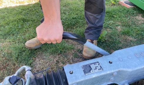
6. Lift the handle behind the tow hitch to release the ball hitch from the towing ball. At the same time turn the jockey wheel handle anticlockwise to lower the jockey wheel and raise the tow bar.
3. Pull jockey wheel release handle [1] and rotate jockey wheel assembly 90º until the wheel is lowered and the jockey assembly is perpendicular to the floor. Turn orange handle until wheel touches the floor.
7. Keep turning until the hitch is raised above the ball and the towing vehicle can be removed easily. Remove vehicle.
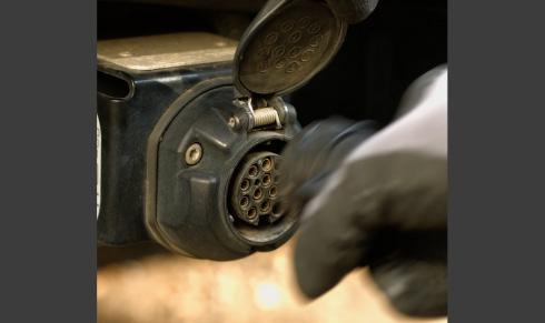
4. Disconnect the lighting cable plug from the socket on the towing vehicle.
8. Turn orange handle clockwise to raise jockey wheel clear of the ground. Pull handle [2] to release and rotate jockey wheel assembly 90º until the wheel is raised parallel to the tow bar.
Your unit is now detached from towing vehicle and ready to use.
3A.3B UNCOUPLING THE UNIT - PIN & EYE
1. Make sure your cabin is situated on firm level ground able to support the weight of the unit. Inspect the ground underneath the unit and check there are no items which may damage the underside of the unit.
2. To uncouple the unit from the towing vehicle, first apply the parking brake.
Remove
3. Pull jockey wheel release handle [1] and rotate jockey wheel assembly 90º until the wheel is lowered and the jockey assembly is perpendicular to the floor. Turn orange handle until wheel touches the floor.
4. Disconnect the lighting cable plug from the socket on the towing vehicle.
Turn orange jockey wheel handle clockwise to raise wheel clear of ground. Pull handle [3] to release and rotate jockey wheel assembly 90º until the wheel is raised parallel to the tow bar.
Your unit is now detached from the towing vehicle and ready to use.
6.
the safety clip [2]
5. Detach the breakaway cable from the tow hitch of the towing vehicle.
2 3A – Transporting The Cabin - 12ft and 16ft Units
7. Remove coupling pin.
14
1
1
2
3
3A.4 DEPLOYING THE UNIT
IMPORTANT
To ensure the optimum perfomance of the solarpowered Deep Green cabin, the unit should be parked in an open exposed area with as little shade as possible over the solar panels. Avoid areas under trees, tunnels or close to tall buildings if at all possible.
4. Remove the remote control from its storage position inside the cabin and connect the remote control’s 7 pin plug to the correct socket on the front of the unit.
8. Ensure there are no obstructions beneath the unit, then press the button closest to the wire on the remote control until the rams have fully retracted and the unit is sitting securely on the ground.
1. Make sure your cabin is situated on firm level ground able to support the weight of the unit. Inspect the ground underneath the unit and check there are no items which may damage the underside of the unit.
2. Uncouple your vehicle from the towing vehicle as described in manual section 3.3 making sure the cabin parking brake is on. Move the towing vehicle away and park at a safe distance.
3. Rotate red Hibernation Switch to the ON position to turn the cabin electrics on. Depending on model, this switch will either be located inside the bench seat in the Canteen or in the wall beneath the bench seat.
7. Find axle rod on front of the cabin. Lift the spring bolt into the open position, then pull out the handle to release the axle locking mechanism. Then release the spring bolt.
12. If the cabin is going to be used straight away, you should leave the Hibernation Switch ON. If it will not be used for a while, then turn the Hibernation switch to the OFF position.
You are now ready to lower your anti-vandal cover.
CAUTION
During use, the unit MUST be uncoupled from the towing vehicle.
CAUTION
The remote control pendant for the hydraulic rams must ALWAYS be disconnected from the socket when not being used.
Operation & Maintenance Manual
5. Press the button furthest from the remote wire to lower the ram cylinders and raise the cabin.
6. Keep pressing until the cabin is fully raised and the wheels are clear of the ground.
10. Release the unit’s parking brake by lowering the lever.
11. Always unplug the remote control unit after use and stow it safely in the cabin.
3A – Transporting The Cabin - 12ft and 16ft Units
15
3A.5 ANTI-VANDAL COVER - FLAP OR COWL
Your welfare unit is protected from theft by an anti-vandal cover with an anti-prise bear-claw lock. Here we show you how to lower your anti-vandal cover into deployed position. To raise it into towing position, just reverse the procedure.
1. Release the anti-loose fastener and safety pin that are holding the cover in position.
2. Gently lower the anti-vandal cover so it covers the electrics. In the case of the cowl, it will cover the whole tow bar.
3. Once in position, lock the cover. Remove the keys and close the lock seal to protect against dirt or damage.
3A.6 USING THE LOW LEVEL LIFTING EYES
IMPORTANT
Before transporting, the following steps must be followed:
• All loose items must be stowed prior to transporting.
When transporting on a lorry, the unit is designed to be safe to transport with a full fresh water tank.
• The Hibernation Switch must be in the OFF position to isolate the electrics and make sure the external PIR-sensor lights do not activate while on the road causing a hazard.
• Toilet waste tanks must be emptied before transporting.
Empty Waste tank and Drinking Water tank in the Canteen.
• Lock all doors, windows and close and lock the security shutters.
• Ensure all umbilical connections are safely disconnected.
CAUTION: The welfare unit is not designed as a payload trailer. Any additional items or material carried in the trailer may exceed its maximum mass. It is the driver’s responsibility to ensure this is not the case.
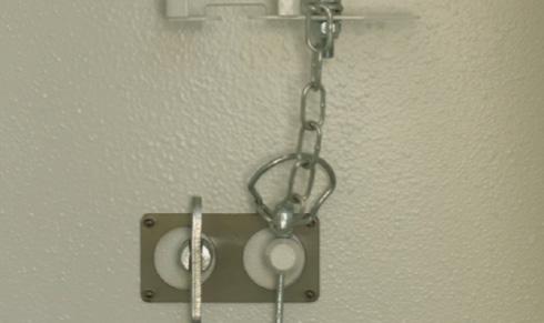
1. First remove the plugging bolt from the eye hole.
5. When lifting is finished please, remove the eyes, replace the plugs and store the lifting eyes in the unit.
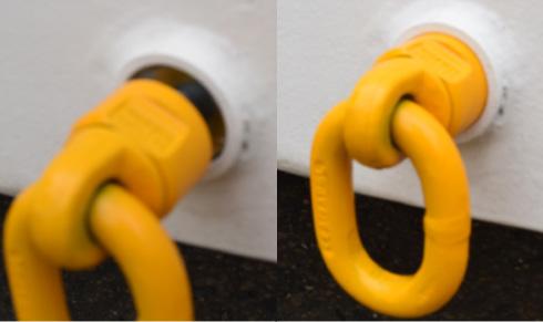
2. Then screw in the lifting eye, ensuring there is a face to face contact between the side of the cabin and the face of the lifting eye.
CAUTION
When lifting a cabin, use ONLY the proprietary lifting eyes supplied from Boss Cabins. One eye must used on each corner of the unit to promotes a level lift. To ensure safe lifting, the eyes must be fitted correctly.
As well as being towed, your mobile welfare unit can also be lifted with a crane and moved around site or lifted onto a lorry for transport. To facilitate this, the unit is equipped with lifting eye holes.
The eye holes are set at a low level which means avoidance of Health & Safety “Working at Height” issues associated with attaching cables to roof-mounted eyes.
Our removable eye system means security is improved as the eyes are not fixed to the units reducing the risk of theft by crane.
Due to the protective solar panel skirts along the top rail of the cabin, it is essential to always use spreader bars when lifting Deep Green cabins using straps or chains so the skirts are not damaged during the lifting process.
To avoid damage to the roof mounted solar panels and protective skirts, the cabin must always be secured to the transport lorry using the low level lifting points rather than lashing over the top.
3. Do this for all four lifting eyes. You are now ready to attach lifting straps or chains.
CAUTION
To avoid damage, ALWAYS use spreader bars when lifting Deep Green cabins with a crane.

4. When lifting a Deep Green cabin using straps or chains, spreader bars must always be used to avoid damage to solar panel skirt.
CAUTION
NEVER secure a Deep Green cabin to the lorry using lashing straps or you will damage the solar panels and skirt.
Operation & Maintenance Manual
3A – Transporting The Cabin - 12ft and 16ft Units
16
TRANSPORTING THE CABIN 20FT & 24FT UNITS 3B
3B.1 PREPARING THE UNIT FOR TOWING20FT & 24FT UNITS
IMPORTANT
Before towing, the following steps must be followed:
All loose items must be stowed prior to towing.
• 20ft and 24ft units are designed to be safe to tow with a full fresh water tank.
• The Hibernation Switch must be in the OFF position to isolate the electrics and make sure the external PIR-sensor lights do not activate while on the road causing a hazard.
• Toilet waste tanks must be emptied
3. Raise the anti-vandal flap into the open position then engage the anti-loose fastener and the safety pin to ensure the cover stays in the towing position when on the road.
7. Depending on when your cabin was built, you may have one of three types of remote control. On all types, press the button furthest from the remote wire to lower the ram cylinders and raise the cabin.
11. Ensure there are no obstructions beneath unit. Press button closest to the pendant wire to retract rams and lower the unit onto the road wheels and jockey wheel. Make sure rams are fully retracted.
before towing.
• Empty Waste tank and Drinking Water tank in the Canteen.
• Lock all doors, windows and close and lock the security shutters.
• Ensure all umbilical connections are safely disconnected.
CAUTION: The welfare unit is not designed as a payload trailer. Any additional items or material carried in the trailer may exceed its maximum mass. It is the driver’s responsibility to ensure this is not the case.
4. Raise the parking brake lever to engage the brake.
8. Keep pressing until the cabin is fully raised and the wheels are clear of the ground.
12. Always unplug the remote control unit after use and stow it safely inside the cabin.
CAUTION
The remote control pendant for the hydraulic rams must ALWAYS be disconnected from the socket when not being used.
1. Before towing, the waste tank must be emptied by a professional company. The cap is found in the toilet floor.
5. Locate the red Hibernation Switch under the bench seat as shown or in the exterior wall of the bench near door. Rotate to the ON position to turn cabin electrics on.
9. Unscrew jockey wheel retainer [2] and drop jockey wheel to a few centimetres above the ground. When wheel is almost touching the floor, fully tighten jockey wheel retainer.
13. Turn the Hibernation Switch to the OFF position.
2. To prepare for towing, first unlock the anti-vandal cover using the key [1]. Remove the key and close the lock seal to prevent water or dirt entry while towing.
6. Remove the remote control from its storage position inside the cabin and connect the remote control’s 7 pin plug to the correct socket on the front of the unit.
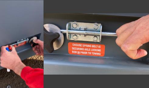
10. Find axle rods on side of the cabin near wheel arch. Slide spring bolt sideways into open position, then push in handle to engage axle locking mechanism. Next release spring bolt making sure it covers washer to stop axle rod from coming out. Repeat for both bolts.
14. Insert the numberplate of the towing vehicle into the numberplate holder clip.
You are now ready to couple your unit to the towing vehicle.
CAUTION
Before towing, the Hibernation Switch must be in the OFF position to completely isolate all electrics and make sure the external PIR-sensor lights do not activate while on the road causing a hazard to other drivers.
3B – Transporting The Cabin - 20ft and 24ft Units
1
18 2
3B.2A ATTACHING UNIT TO TOWING VEHICLE
BALL HITCH
1. To attach your cabin to a towing vehicle it should be in a raised position with wheels on the floor and rams raised. With the unit positioned on level ground apply the parking brake by raising the lever.
5. Attach the breakaway cable to the tow hitch of the towing vehicle and ensure it is safe and operational.
2. Turn the jockey wheel operating handle anti-clockwise to raise the coupling head higher than the towing vehicle’s tow ball. Then manoeuvre the towing vehicle so the ball is beneath the ball coupler.
6. Connect the lighting cable plug to the socket of the towing vehicle and ensure all lights are functioning correctly.
3. Raise and hold the coupling head handle in the up position, and then turn the jockey wheel clockwise to lower the coupling onto the tow ball.
7. Unscrew jockey wheel retainer [1] and raise jockey wheel off the ground as close to the tow bar as possible. When wheel is fully raised, tighten jockey wheel retainer so the wheel is secure.
4. When almost fully lowered let go of the coupling head handle and allow it to snap closed over the tow ball. Check that the coupling head is fully engaged on the tow ball.
8. Secure the jockey wheel with the attached safety clip [2], then lower the parking brake to release the trailer wheels before towing.
Your unit is now attached and ready to be towed.
3B.2B ATTACHING UNIT TO TOWING VEHICLEPIN & EYE
1. To attach your cabin to a towing vehicle it should be in a raised position with wheels on the floor and rams raised. With the unit positioned on level ground apply the parking brake by raising the lever.
5. Attach the breakaway cable to the tow hitch of the towing vehicle and ensure it is safe and operational.
2. Turn the orange jockey wheel handle to adjust the eye to the right height then manoeuvre the towing vehicle so the eye is aligned with the pin holes on the vehicle tow bar.
6. Connect the lighting cable plug to the socket of the towing vehicle and ensure all lights are functioning correctly.
3. Insert coupling pin.
4. Secure with the safety clip [1]
7. Unscrew jockey wheel retainer [2] and raise jockey wheel off the ground as close to the tow bar as possible. When wheel is fully raised, tighten jockey wheel retainer so the wheel is secure.
8. Secure the jockey wheel with the attached safety clip [3], then lower the parking brake to release the trailer wheels before towing.
Your unit is now attached and ready to be towed.
2
1
– Transporting The Cabin - 20ft and 24ft Units
3 3B
19 1 2
3B.3A UNCOUPLING THE UNIT - BALL HITCH
1. Make sure your cabin is situated on firm level ground able to support the weight of the unit. Inspect the ground underneath the unit and check there are no items which may damage the underside of the unit.
5. Detach the breakaway cable from the tow hitch of the towing vehicle.
2. To uncouple the unit from the towing vehicle, first apply the parking brake.
6. Lift the handle behind the tow hitch to release the ball hitch from the towing ball. At the same time turn the jockey wheel handle anticlockwise to lower the jockey wheel and raise the tow bar.
3. Unscrew jockey wheel retainer [1] and drop jockey wheel to the ground. When wheel is touching floor, fully tighten jockey wheel retainer.
7. Keep turning until the hitch is raised above the ball and the towing vehicle can be removed easily.
4. Disconnect the lighting cable plug from the socket on the towing vehicle.
2
8 Unscrew jockey wheel retainer [2] and raise wheel off ground as close to tow bar as possible. When wheel is fully raised, tighten jockey wheel retainer so the wheel is secure. Secure with attached safety clip.
Your unit is now detached from the towing vehicle and ready to use.
3B.3B UNCOUPLING THE UNIT - PIN & EYE
1. Make sure your cabin is situated on firm level ground able to support the weight of the unit. Inspect the ground underneath the unit and check there are no items which may damage the underside of the unit.
2. To uncouple the unit from the towing vehicle, first apply the parking brake.
3. Unscrew jockey wheel retainer [1] and drop jockey wheel to the ground. When wheel is touching floor, fully tighten jockey wheel retainer.
3 1 1
4. Disconnect the lighting cable plug from the socket on the towing vehicle.
6. Remove the safety clip [2]
5. Detach the breakaway cable from the tow hitch of the towing vehicle.
7. Remove coupling pin. 3B – Transporting The Cabin - 20ft and 24ft Units 20
2
8. Unscrew jockey wheel retainer [3] and raise wheel off ground as close to tow bar as possible. When wheel is fully raised, tighten jockey wheel retainer so the wheel is secure. Secure with attached safety clip.
Your unit is now detached from the towing vehicle and ready to use.
3B.4 DEPLOYING THE UNIT
IMPORTANT
To ensure the optimum perfomance of the solarpowered Deep Green cabin, the unit should be parked in an open exposed area with as little shade as possible over the solar panels. Avoid areas under trees, tunnels or close to tall buildings if at all possible.
4. Remove the remote control from its storage position inside the cabin and connect the remote control’s 7 pin plug to the correct socket on the front of the unit.
8. Ensure there are no obstructions beneath the unit, then press the button closest to the wire on the remote control until the rams have fully retracted and the unit is sitting securely on the ground.
1. Make sure your cabin is situated on firm level ground able to support the weight of the unit. Inspect the ground underneath the unit and check there are no items which may damage the underside of the unit.
5. Press the button furthest from the remote wire to lower the ram cylinders and raise the cabin.
2. Uncouple your vehicle from the towing vehicle as described in manual section 3.3 making sure the cabin parking brake is on. Move the towing vehicle away and park at a safe distance.
6. Keep pressing until the cabin is fully raised and the wheels are clear of the ground.
10. Release the unit’s parking brake by lowering the lever.
11. Always unplug the remote control unit after use and stow it safely in the cabin.
3. Rotate the red Hibernation Switch to the ON position to turn the cabin electrics on. Dependent on model, this switch will either be located inside the bench seat in the Canteen or in the wall beneath the bench seat.
7. Find axle rods on side of the cabin near wheel arch. Slide spring bolt sideways into open position, then pull handle out to release axle locking mechanism so the wheels can retract when cabin is lowered. Release spring bolts. Repeat for both bolts.
12. If the cabin is going to be used straight away, you should leave the Hibernation Switch ON. If it will not be used for a while, then turn the Hibernation switch to the OFF position.
You are now ready to lower your anti-vandal cover.
CAUTION
During use, the unit MUST be uncoupled from the towing vehicle.
CAUTION
The remote control pendant for the hydraulic rams must ALWAYS be disconnected from the socket when not being used.
3B – Transporting The Cabin - 20ft and 24ft Units 21
3B.5 ANTI-VANDAL COVER - FLAP
Your welfare unit is protected from theft by an anti-vandal cover with an anti-prise bear-claw lock. Here we show you how to lower your anti-vandal cover into deployed position. To raise it into towing position, just reverse the procedure.
1. Release the anti-loose fastener and safety pin that are holding the flap in position.
2. Gently lower the anti-vandal cover so it covers the electrics.
3. Once in position, lock the cover. Remove the keys and close the lock seal to protect against dirt or damage.
3B.6 USING THE LOW LEVEL LIFTING EYES
IMPORTANT
Before transporting, the following steps must be followed:
• All loose items must be stowed prior to transporting.
• The unit is designed to be safe to transport with a full fresh water tank.
The Hibernation Switch must be in the OFF position to completely isolate all electrics and make sure the external PIR-sensor lights do not activate while on the road causing a hazard.
Toilet waste tanks must be emptied before transport.
• Empty Waste tank and Drinking Water tank in the Canteen.
Lock all doors, windows and close and lock the security shutters.
• Ensure all umbilical connections are safely disconnected.
CAUTION: The welfare unit is not designed as a payload trailer. Any additional items or material carried in the trailer may exceed its maximum mass. It is the driver’s responsibility to ensure this is not the case.
1. First remove the plugging bolt from the eye hole.
5. When lifting is finished please, remove the eyes, replace the plugs and store the lifting eyes in the unit.
2. Then screw in the lifting eye, ensuring there is a face to face contact between the side of the cabin and the face of the lifting eye.
CAUTION
When lifting a cabin, use ONLY the proprietary lifting eyes supplied from Boss Cabins. One eye must used on each corner of the unit to promotes a level lift. To ensure safe lifting, the eyes must be fitted correctly.
As well as being towed, your mobile welfare unit can also be lifted with a crane and moved around site or lifted onto a lorry for transport. To facilitate this, the unit is equipped with lifting eye holes.
The eye holes are set at a low level which means avoidance of Health & Safety “Working at Height” issues associated with attaching cables to roof-mounted eyes.
Our removable eye system means security is improved as the eyes are not fixed to the units reducing the risk of theft by crane.
Due to the protective solar panel skirts along the top rail of the cabin, it is essential to always use spreader bars when lifting Deep Green cabins using straps or chains so the skirts are not damaged during the lifting process.
To avoid damage to the roof mounted solar panels and protective skirts, the cabin must always be secured to the transport lorry using the low level lifting points rather than lashing over the top.
3. Do this for all four lifting eyes. You are now ready to attach lifting straps or chains.
CAUTION
To avoid damage, ALWAYS use spreader bars when lifting Deep Green cabins with a crane.
4. When lifting a Deep Green cabin using straps or chains, spreader bars must always be used to avoid damage to solar panel skirt.
CAUTION
NEVER secure a Deep Green cabin to the lorry using lashing straps or you will damage the solar panels and skirt.
– Transporting The Cabin - 20ft and 24ft Units 22
3B
POWERING THE UNIT
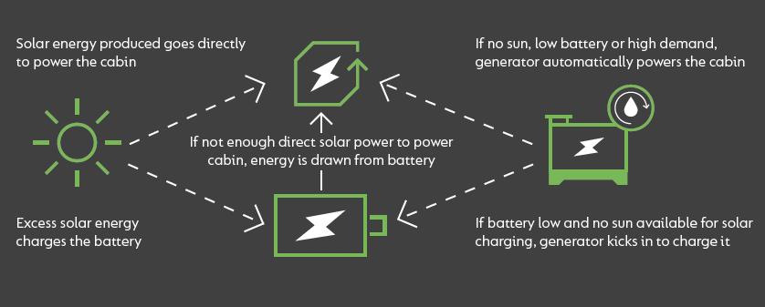
Once your welfare cabin is safely deployed, you need to get it up and running. This Deep Green unit can be powered either from an external power source or by an onboard SOLARFlowTM electrical system which harvests energy from solar panels on the roof to charge the battery. All electrical items run from battery power alone with no need for a generator to be running.
If, on occasions, the solar panels do not generate enough energy, a back-up generator will turn on automatically to recharge the battery.
4
4. POWERING THE DEEP GREEN UNIT
This welfare cabin is fitted with a unique SOLARFlowTM electrical system which is powered almost entirely by an array of solar panels mounted on the roof. Energy generated by these solar panels is fed into a 200Ah lithium ion battery.
The energy stored in the 5.12kVa battery is used to power all the electrical items in the cabin. These include PIR-sensor 24V lighting inside and out; low-power 3-pin plug sockets for computers etc.; kettle; microwave; instant water heaters; electric hand dryers; USB charging points; and the UV water sterilisation system.
In the event that the solar panels do not generate enough energy (in low light conditions, unfavourable positioning, or extreme bad weather) a 3.5kVA back-up generator will turn on automatically to recharge the battery for a period until it reaches an acceptable level of charge.
The cabin may also be powered using an external power source.
In Section 4 of the Manual, we explain how to use the various power sources.
CAUTION: To ensure the optimum perfomance of the solar-powered Deep Green, the unit should be parked in an open exposed area with as little shade as possible over the solar panels. Avoid areas under trees, tunnels or close to tall buildings if at all possible.
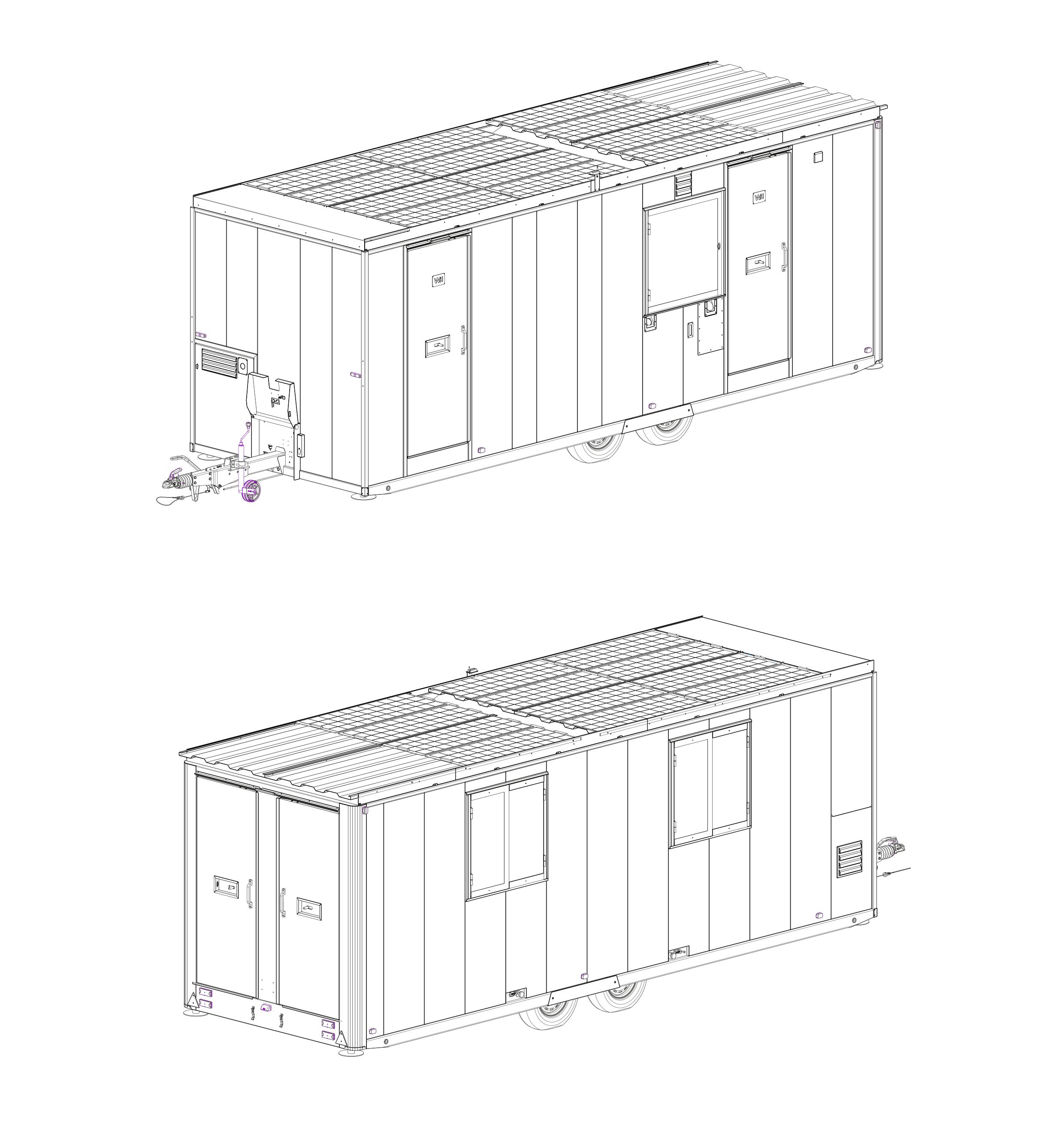
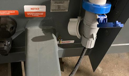
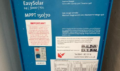
4.1 USING AN EXTERNAL POWER SOURCE
The welfare unit can be connected to an external electrical power supply using a standard 32A 230V AC cable connected to the socket located under the anti-vandal cover.
Before connecting this cabin installation to the mains supply, check that:
a) the supply available at the site supply point is suitable for the cabin’s electrical installations and appliances;
b) the voltage and frequency and current ratings are suitable;
c) the cabin main Hibernation Switch is in the OFF position.
IN THE CASE OF DOUBT OR, IF AFTER CARRYING OUT THE ABOVE PROCEDURE, THE SUPPLY DOES NOT BECOME AVAILABLE OR IF THE SUPPLY FAILS, CONSULT THE SITE OPERATOR OR THE OPERATOR’S AGENT OR A QUALIFIED ELECTRICIAN.
CAUTION
The cabin supply flexible cable must be fully unncoiled to avoid damage by overheating.
IMPORTANT
This cabin is internally supplied with a TN-S earthing arrangement. In accordance with Regulation 717.411.4 BS7671:2018:
THIS CABIN SHALL NOT BE CONNECTED TO A PME SUPPLY
EXTERNAL SUPPLY MUST BE:
• Single phase
• 230V
• 32A
• No less than 2.5mm2 wire
• Cables must meet H07RN-F (BS-EN 50525-2-21) standard as set out in Regulation 717.52 BS7671:2018
Operation & Maintenance Manual
4 – Powering The Unit - Deep Green
24
4.1.1 TO CONNECT EXTERNAL ELECRICITY SUPPLY
1. Before connnecting make sure the cabin Hibernation Switch in the OFF position.
2 Open the cover to the inlet socket on the front of this cabin and insert the connector of the supply flexible cable. Next raise the cover of the electricity outlet provided at the site supply point and insert the plug of the supply cable.
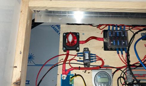
4. When the two ends of the supply cable are inserted into their respective sockets, turn the cabin Hibernation Switch to the ON position. Next it is essential to check the operation of residual current devices (RCDs/RCBOs) fitted in cabin. To perform test, locate main RCD panel. Depending on the model of cabin, this will be located either under right hand bench in Canteen (blue box shown) or on the wall in the Canteen.


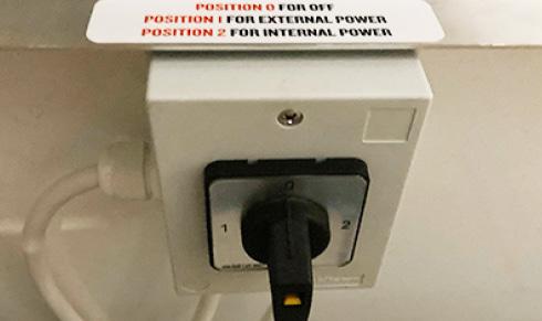
3. Put the Internal/External Power Selector switch in the correct position for External power. This switch is located inside the bench in the Canteen. You may have one of two types of Selector switch in your cabin.
Type A: 0 - OFF, 1 - External power source, 2 - Internal solar, battery and generator power
Type B: CENTRE - OFF; UP - External power source; DOWN - Internal solar, battery, and generator power
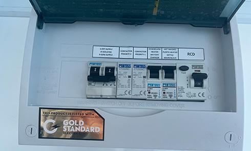
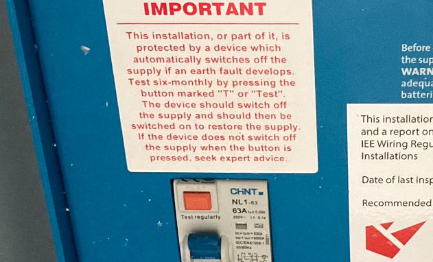
RCD Board - Type A: First check that RCD Main Power Outlet paddle [1] is in the ON position. Press orange TEST button [2]. Main Power Outlet paddle should flip down to OFF position and power will be cut to all circuits. If this does not happen, the RCD is faulty and electrical system should not be used until rectified by qualified personnel. To reset RCD or any MCB push the paddles to ON position.
RCD board - Type B: To test the Main RCD open the cover and ensure the RCD paddle [3] is in the “ON” position. Press the TEST button [4], the paddle will move to the down “OFF” position and power will be cut to all circuits. If this does not happen, the RCD is faulty and the electrical system should not be used until rectified by qualified personnel. To reset the RCD or any MCB push the paddles to the “ON” position.
4.1.2 TO DISCONNECT EXTERNAL ELECTRICITY SUPPLY
1. Switch OFF the cabin main isolating Hibernation Switch.
2. To disconnect, move the Internal/External Power Selector switch first to OFF then to the correct position for Internal power. This switch is located inside the bench in the Canteen. You may have one of two types of Selector switch in your cabin.
Type A: 0 - OFF, 1 - External power source, 2 - Internal solar, battery and generator power
Type B: CENTRE - OFF; UP - External power source; DOWN - Internal solar, battery, and generator power.
3. Unplug the cable first from the site supply point and then from the cabin inlet connector.
PERIODIC INSPECTION
Preferably not less than once every three years and annually if the cabin is used frequently, the cabin’s electrical installation and supply cables should be inspected and tested and a report on their condition obtained as prescribed in BS 7671 Requirements for Electrical Installations published by the Institution of Engineering and Technology & BSI.
Operation & Maintenance Manual 4 – Powering The Unit - Deep Green
1 2
3
25
4
4.2 USING THE INTERNAL SOLARFLOW TM HYBRID POWER SYSTEM
The SOLARFlowTM electrical system uses a 200Ah 5.12kVA battery to power all electrical appliances in the unit. The battery is charged with energy generated by an array of solar panels mounted on the roof.
In certain conditions (extended periods of low light, unfavourable positioning, or extreme bad weather) the solar panels alone may not be able to create sufficient energy to supply the battery with enough charge to power the unit. If this happens and the battery charge level drops below a certain point, the back-up generator will automatically start up and run until the battery reaches an acceptable charge level. Once this level is reached, the generator will turn off automatically. No user intervention is necessary.
In the rest of Section 4, we explain how to operate and maintain the SOLARFlowTM hybrid system.
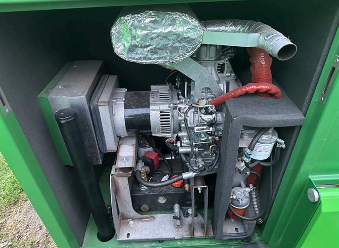
4.3 GENERATOR CHECKS BEFORE USE
Your welfare cabin is fitted with a 3.5kVA RedBox Infinity generator.
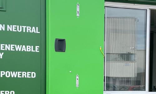
This on-board generator is used to charge the battery at times when not enough solar energy is being produced. The generator is located in a self contained compartment at the front of the unit. The generator control panel is located in a panel beneath the sink in the Canteen.
REDBOX INFINITY GENERATOR
Your
1.
2. Canister secondary fuel filter
3. Oil filter
4. Oil filler hole (orange cap)
5. Oil min/max gauges located on extended sump
6.
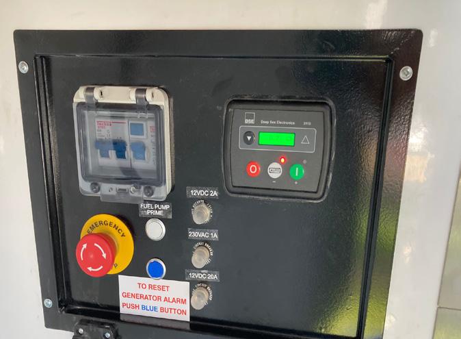
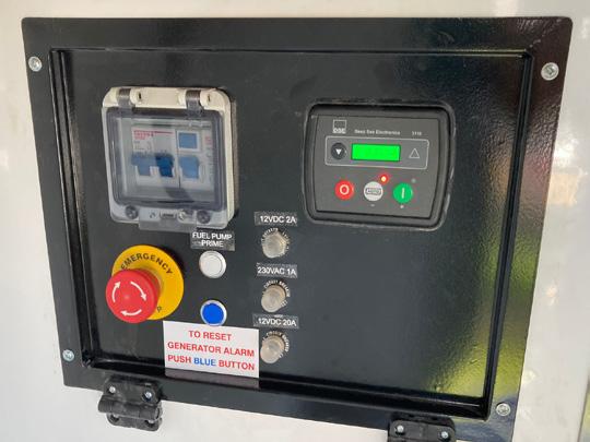
GENERATOR CONTROL PANEL
The main generator control panel is located in the Canteen on the wall under the sink. This contains:
1.
2.
3.
4.
Before use, it is important to always check your oil and fuel levels and top up as necessary.
Service Intervals Redbox Infinity 2000 hour
An RCD panel
The DSE
device
generator control
Fuel pump prime button
The blue generator alarm reset button
Circuit breakers for the 12V DC 2A and 20A systems and for the 220V AC 1 A system 1 2 3 4
5.
RedBox Infinity generator is located in the compartment on the front of cabin. Key features are:
Exhaust
outlet
Fuel filter
CAUTION 5 1 2 5 6 4 26 4 – Powering The Unit - Deep Green 3
4.3.1 OIL CHECK REDBOX INFINITY GENERATOR
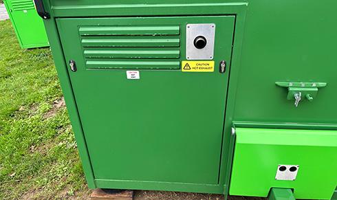
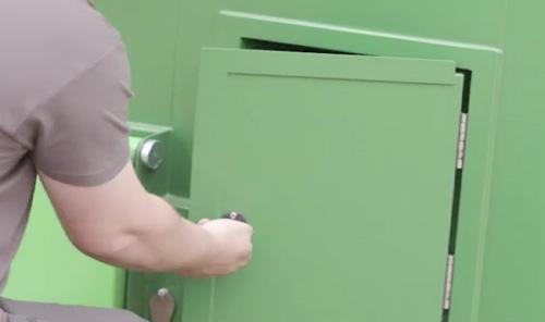
1. To check the oil, you must access the generator. Use the keys provided to unlock the two locks on the generator compartment door at the front of the cabin. Then remove the generator cover.
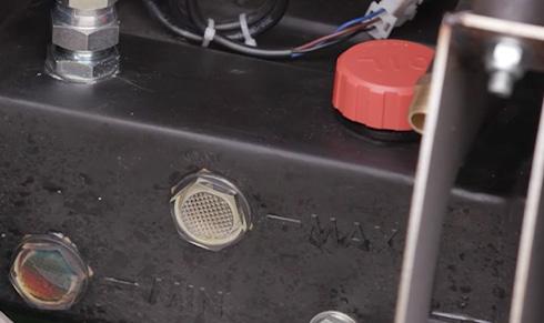
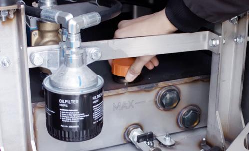
2. Check the oil using the min/max sight gauges on the front of the generator sump tank below the engine. If oil is needed, remove the orange cap on top of the sump tank and fill with SAE 15W-40 oil until the oil level in the gauge reaches the MAX marker. Do not use the dipstick to check oil or fill.
4.3.2 FUEL CHECK AND FILL

1. There are three ways to check the fuel level in the Deep Green cabin.
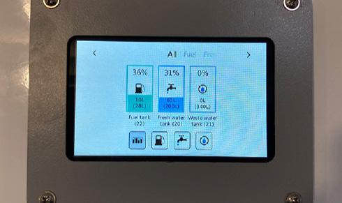
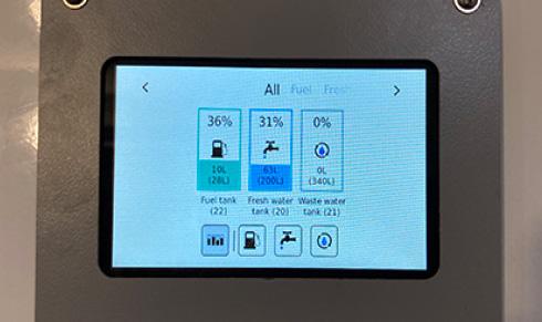
1. Using the Gauge Panel in the Canteen. When the electrics are switched on, this Gauge Panel displays the levels of the fuel, fresh water and waste tanks.
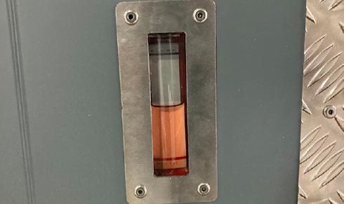
2. Using the physical fuel gauge which is found in the right side of the cabin below the Drying room in 24ft units and in the fuel compartment in the front of the cabin in 12ft, 16ft and 20ft units.
3. Cabin owners that have access to the SOLARTrackTM remote monitoring system are able to see the cabin fuel level using this system. An email alert is also sent to the SOLARTrackTM user when the fuel level falls below a defined level.
2 1
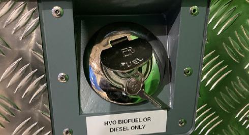
2. If fuel is needed in the Deep Green 24ft unit, unlock and remove the fuel tank cap [1] located on the left side of the cabin below the Drying room. If you have a 12ft, 16ft or
the
in the base of the fuel
the
the
Fill the fuel reservoir with the correct amount of HVO biofuel or traditional white diesel. Do NOT use bio diesel. Replace and lock the cap and/or the fuel compartment door as appropriate.
* Use SAE 15W-40 oil which is suitable in most ambient temperature conditions. In extreme temperatures below -15º or above 38º, please refer to your generator operations manual for further advice.
SOLARTrackTM
All tank levels in Deep Green cabins can be remotely monitored by authorised users via the online SOLARTrackTM system. Contact your cabin provider to see if you have access to this system and for instructions on how to use it.
Operation & Maintenance Manual 4 – Powering The Unit - Deep Green
20ft unit,
fuel filler cap [3] is located
compartment [2] in
front of
cabin.
3
27
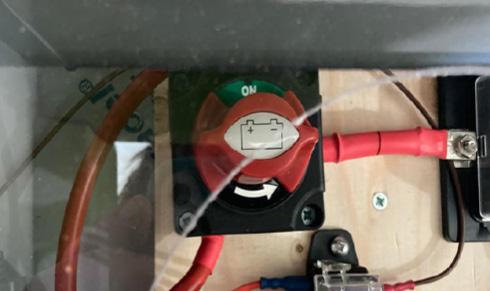
4.4 TURNING ON THE ELECTRICAL SYSTEM
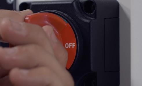
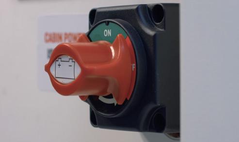
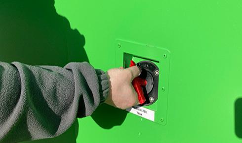
1. To switch on the electrical system in your cabin, locate the Hibernation Switch. Depending on the cabin model, this will either be located in the panel below the bench seat near the door or in 24ft units, it is found inside the right hand bench seat in the far corner as pictured above. Turn the switch to reveal the green ON sign.


2. Next make sure the Internal/External Power Selector switch is in the correct position. This switch is located inside the bench in the Canteen. You will have one of two types of Selector switch in your cabin.
Type A: 0 - OFF, 1 - External power source, 2 - Internal solar, battery and generator power.
Type B: CENTRE - OFF; UP - External power source; DOWN - Internal solar, battery, and generator power.

3. Check that the Solar Charger Switch is in the ON position. This is located inside the bench seat in the Canteen. If this is switched OFF, the solar panels will not charge the battery.
4.5 LEAVING THE CABIN
At the end of the day or when leaving the cabin for an extended period, always turn the cabin Hibernation switch OFF.
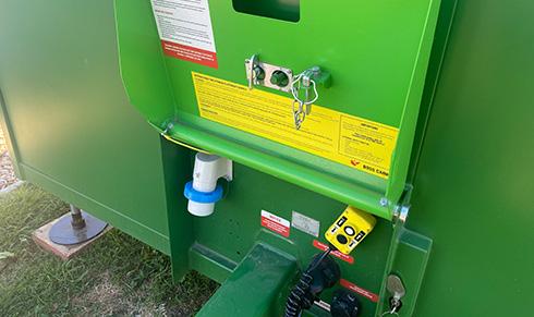
ELECTRICS NOT WORKING OR GENERATOR NOT AUTOMATICALLY STARTING TO CHARGE BATTERY? CHECK E-STOP
Has E-STOP button [1] been pressed by accident? If pressed, an alarm triangle will illuminate [2] and this symbol will show on DSE display [3].

To release, rotate E-STOP button clockwise. Next press blue RESET button [4] on Generator Control Panel then check alarm symbol is no longer illuminated.
E-STOP button must only be pressed in a genuine emergency - in case of fire or risk to life.
Operation & Maintenance Manual
4 – Powering The Unit - Deep Green
1
4 2
3
to
28
Turn the heater off in order
conserve energy in this Deep Green eco welfare cabin.
ELECTRICAL SYSTEM & EQUIPMENT
Deep Green welfare cabins are fitted with a SOLARFlowTM hybrid electrical system which harvests energy from solar panels on the roof to charge a lithium ion battery. All electrical items run from battery power alone with no need for a generator to be running.
If, on occasions, the solar panels do not generate enough energy, the back-up generator will turn on automatically to recharge the battery.
5
5 USING THE ELECTRICAL SYSTEM
Your cabin is fitted with a highly energy-efficient SOLARFlowTM electrical system. Energy generated by the roof-mounted solar panels or back-up generator is stored in the 5.12kVA lithium Ion battery and used to power all the electrical items in the cabin. These include PIR-sensor 24V lighting inside and out; low-power 3-pin plug sockets for computers etc.; kettle; microwave; optional fridge; instant hot water units; lowpower hot air hand dryers; USB charging points; and the UV water sterilisation system.
In Section 5, we explain how to use all the various electrical items and appliances in your cabin.

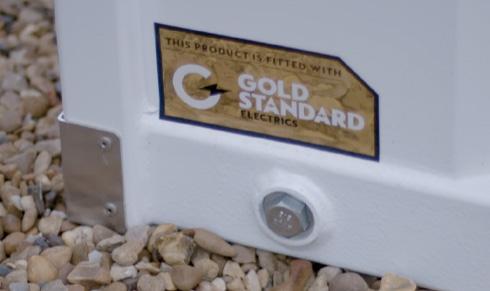
All Deep Green units have certified Gold Standard electrics which means that our cabin installations meet or surpass all current UK and EU legislation requirements.
TM
SOLARFlow
5.1 HIBERNATION ISOLATOR SWITCH

Before using any electrical items in the cabin, the Hibernation switch must be turned to the green ON position. In some 24ft units, the Hibernation Switch is found inside the right hand bench seat in towards the rear of the Canteen.
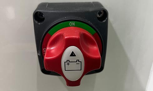
In most models, the Hibernation switch is found in the Canteen wall beneath the bench seat. When the cabin is to be left unused for a period of time, and at the end of each day, turn the Hibernation Switch to the OFF position before leaving the cabin. This will prevent the cabin from using electricity unnecessarily.
CAUTION
Before towing, the Hibernation Switch must be in the OFF position to completely isolate all electrics and make sure the external PIR-sensor lights do not activate while on the road causing a hazard to other drivers.
CAUTION
When leaving the cabin for an extended period. always turn to Hibernation switch OFF. This will ensure that no electricity is used from the battery and the generator will not start up automatically to recharge the battery.
5.2 INTERNAL/EXTERNAL POWER
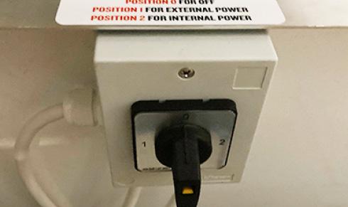
Always make sure the Internal/External Power Selector is in the correct position. This is located inside the right hand bench in the Canteen. You will have one of two types of Selector switch in your cabin.
Type A: 0 - OFF, 1 - External power source, 2 - Internal solar, battery and generator power
Type B: CENTRE - OFF; UP - External power source; DOWN - Internal solar, battery, and generator power
Operation & Maintenance Manual
5 – Electrical System & Equipment - Deep Green
A B
30
5.3 USING THE ELECTRICAL EQUIPMENT
Your Deep Green welfare cabin is equipped with various items of electrical equipment. Here we explain how to use each one in conjunction with the SOLARFlowTM electrical system.
5.3.1 24V LED LIGHTING
The cabin is fitted as standard with 24V LED ceiling lights which run off battery power. The Hibernation switch must be in the ON position for all LED lights to function.
All 24V LED ceiling lights in the Canteen, Office, Toilets and Drying areas are operated via PIR sensor so there is no need to switch on, they will come on automatically as someone enters the room and switch off again after they leave. If you are sitting still and the lights go out, simply make a movement and the sensor will detect it and the lights will come back on again.
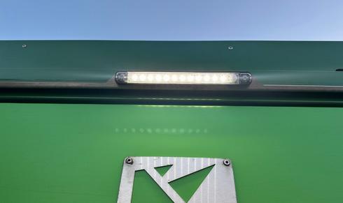
There are also exterior PIR-sensor activated 24V LED lights above the Canteen, Office and Toilet doors to improve visibility in low light conditions on site and help avoid trip hazards which come on when someone steps near the cabin. As well as a PIR-sensor, these lights incoporate a daylight-sensor so will only operate in dark or low-light conditions.
In order that these lights do not come on while transporting the cabin and cause a road hazard, it is essential to turn the Hibernation Switch to the OFF position before the cabin is moved.
5.3.2 WATER STERILISATION SYSTEM


Type A - LED UV sterilisation. If your cabin is fitted with an LED UV sterilisation unit, this functions completely automatically and you do not need to turn on an isolator.

The rain water drain should be checked regularly for obstructions such as fallen leaves or other debris. Clear any obstructions and dispose of them.
In order to protect the planet’s water resources, this Deep Green cabin incorporates a patented rain water harvesting and grey water recycling system, Waste Management ProTM. Rain water is harvested from the roof, sieved for debris and fine particles before being sterilised in one of several ways dependent on the model of your cabin.
Type B - Non-LED UV sterilisation. If your cabin has a non-LED sterilisation system there will be an isolator in the Office (20ft and 24ft), or it will be located under one of the benches towards the rear of the canteen (12ft and 16ft). This should be turned on at all times when water might be used.
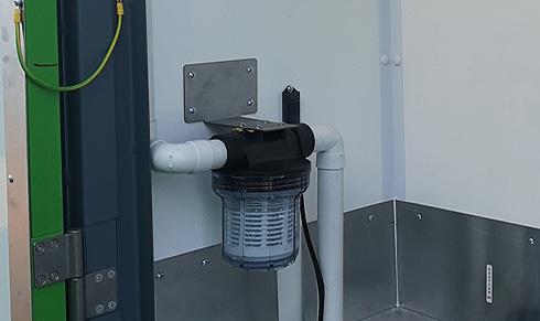
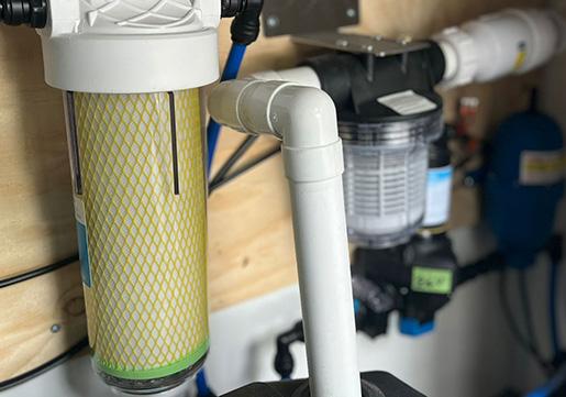
The particle filter found should also be cleaned and the filter replaced regularly by an authorised service engineer. Depending on model, this is located either in the Drying room, the toilet cubicle or under the sink in the toilet.
Type C - Chlorine sterilisation. Some models are fitted with a chlorine sterilisation system. Please insert a chlorine tab into the entry point shown. When the chlorine tab has fully dissolved, add another. This should be checked regularly and at every toilet service.
NOTE
For more information on the water sterilisation system, see section 7.2.
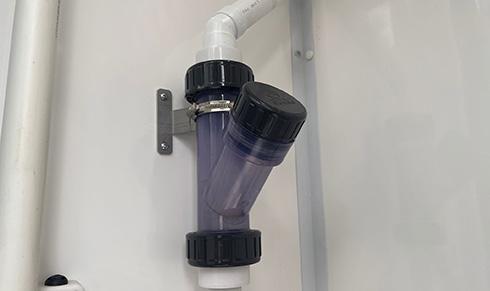
Type D - Micron sterilisation filter. This sterilises water passing betweeen the fresh water tank and the hot wash units. These filters are located under the desk in the office in the 20ft and 24ft units. In the 12ft and 16ft units, they are located under the sinks in the toilets. The micron filter cartridge should be changed every 12 months. For more details, refer to the manufacturer’s instructions.
IMPORTANT
If the bulb in the non-LED UV sterilisation system fails, a warning beep will be emitted from the unit and the green light on the unit will go off. To change the bulb, you must consult the manufacturer’s instructions. Do not open the UV unit before reading the instructions.
Operation & Maintenance Manual 5 – Electrical System & Equipment - Deep Green
31
5.3.3 CANTEEN & TOILETS HOT WATER HAND WASH & LOW POWER HAND DRYER
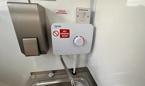
The water for the hand wash sinks comes from the main fresh water tank. After being sterilised it passes to the instant hot wash unit where it is heated on demand. To start the unit, turn the dial to the required temperature. The water is heated instantly and starts to flow. The temperature of the water can be controlled by turning the dial from 1 – Cool to 10 – Hot.
CAUTION: To avoid scalding, always set temperature low to start.
5.3.4 KITCHEN APPLIANCES
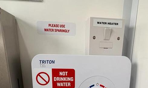
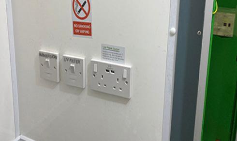
To operate the instant hot water hand wash unit, the Hibernation Switch switch must be ON. Make sure the water heater isolator is also switched on. This is located on the wall near the unit.
If water does not come out of the taps when pressed, check the water tank level using the gauge in the Canteen. If it is low, fill the water tank.
Toilet cubicles are fitted with lowpower hands-free electric hand dryers for hygiene and convenience. To operate the hand dryer, simply place your hands beneath the air outlet and hot air will flow. The hand dryer isolator [1] must be in the ON position for the hand dryer to function.

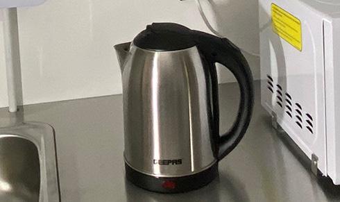
The unit’s food preparation area is supplied as standard with a 1500W kettle to make hot drinks and a 700W microwave for hot food preparation. To use these, the Hibernation switch must be ON. These items all have individual wired isolators - make sure these are also in the ON position.
5.3.5 USB CHARGING POINTS
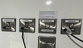
For reasons of energy efficiency in this Deep Green unit, the kettle and microwave are operated individually. Before using either one, make sure power is directed correctly using the selector switch [1]
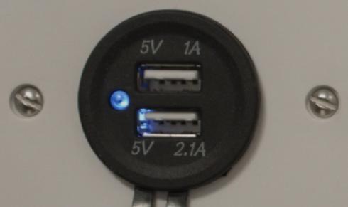
24V USB charging points are provided in the Canteen and Office (if applicable) to enable mobile phones, tablets and notebooks to be charged from the cabin’s battery. The Hibernation switch must be in the ON position to use.
In the Canteen, these USB sockets are located in the wall below the bench seating. In the Office they are found in the plug sockets.
5.3.6 LOW POWER 500W 230V 3-PIN PLUG SOCKETS
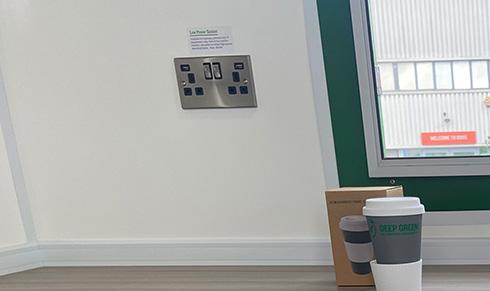
The Deep Green welfare cabin is fitted with low power 500W 3-pin plug sockets in the Canteen and Office (if applicable). These can power 230V devices that do not have a large power consumption, such as laptops, printers and IT equipment only.
These sockets are not designed to be used for heaters, site plant or other high power electrical items. Maximum 500W.
In the Canteen, double 3-pin sockets (if available) are located in the wall below the bench seating. If the unit has an Office, there are double sockets in the wall near the desk.
Operation & Maintenance Manual 5 – Electrical System & Equipment - Deep Green
1
1 32
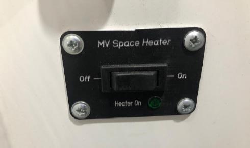
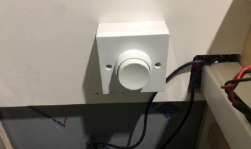
5.4 USING THE HEATER
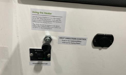
Your Deep Green welfare cabin is fitted with a low-consumption air-blown heater that runs on HVO biofuel using 0.25 litres per hour to function. This provides heat for the Canteen, Office (if applicable) and Drying area (if applicable). Fuel for the heater is fed automatically from the main cabin fuel tank. The heater will run on HVO biofuel or white diesel, the same fuel as the generator. Please follow these instructions on how to operate. The
To use the air-blown heating system, press the switch ON. Unless turned OFF manually, this will run for four hours then switch off automatically. To restart, turn on again.
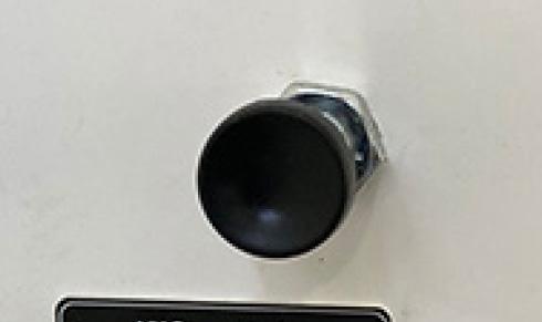
In units with a Drying Room, the warm air from the heating system can be directed either to the Canteen and Office areas or to the Drying Room.
To direct heat to Canteen and Office make sure the knob is pushed IN.
To send heat to the Drying Room, pull the knob OUT.
5.5 ELECTRICAL INSTALLATIONS
Depending on the model and age of your Deep Green cabin, it will have one of these two types of RCD board.
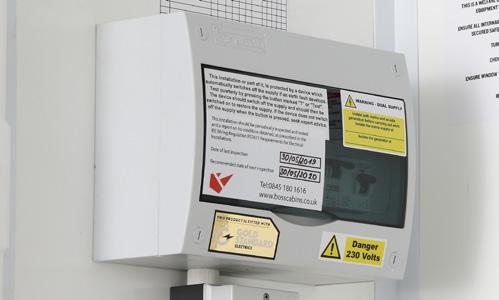
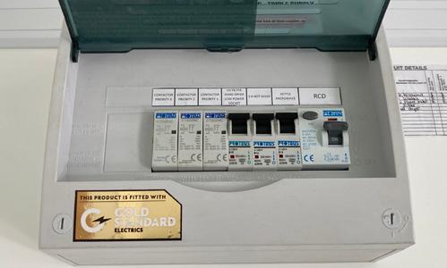
TYPE A - In most Deep Green units, the RCD board will be located on the wall in the Canteen or the Office. It will contain a RCD Main switch and Test button, and individual MCBs to protect the electrical circuits for the vehicle.
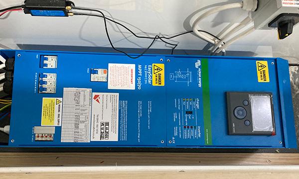
TYPE B - In units with an RCD board integrated to the solar system, you will find the distribution board located in the right hand bench seat int the Canteen of the welfare unit. It contains an RCD Main Power Outlet switch, an orange Test button, and individual MCBs to protect the electrical circuits for the cabin.
NOTE 2
TYPE A TEST PROCEDURE - To test the Main RCD open the cover and ensure the RCD paddle [1] is in the “ON” position. Press the TEST button [2], the paddle will move to the down “OFF” position and power will be cut to all circuits. If this does not happen the RCD is faulty and the electrical system should not be used until rectified by qualified personnel. To reset the RCD or any MCB push the paddles to the “ON” position.
1 2 33
TYPE B TEST PROCEDURE - To test the operation of residual current devices (RCDs/RCBOs) fitted in the cabin, first check that the RCD Main Power Outlet paddle [1] is in the ON position. Press the orange TEST button [2] .The Main Power Outlet paddle should flip down to the OFF position and power will be cut to all circuits. If this does not happen, the RCD is faulty and the electrical system should not be used until rectified by qualified personnel. To reset the RCD or any MCB push the paddles to the ON position.
Operation & Maintenance Manual 5 – Electrical System & Equipment - Deep Green
controls to operate the Heater are located in the Canteen in the wall below the bench seat.
The Hibernation switch must
the heater
function.
NOTE:
be ON for
to
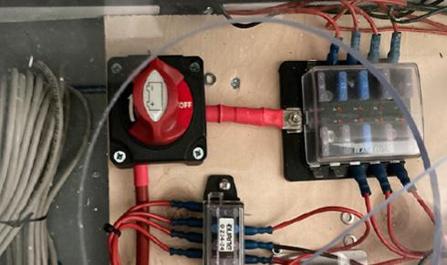
FUSE BOX (230V DC DISTRIBUTION)
5.5.1
The RCD board function should always be checked when a unit is delivered to site. It should also be checked periodically every six months even if the cabin has not been moved. 1
5.5.2 LITHIUM ION BATTERY
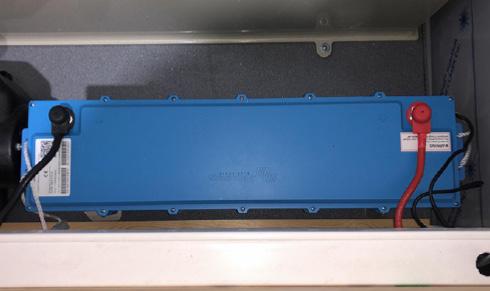
Your cabin is fitted with a high-performance 200Ah 5.12kVA lithium ion battery which is located beneath the bench seating in the Canteen. This battery supplies electricity for the 24V and 230V electrical items.
The battery compartment is locked to make sure unauthorised staff do not touch the battery.
5.5.3 SOLAR PANELS AND INVERTOR


To ensure optimum solar energy capture, make sure the unit is located in a position with as much full direct sunlight as possible. Do not position in dark or shaded areas such as under trees, inside buildings, under bridges etc.
On the roof of the cabin, there is a bank of 150W flexible solar panels which generate energy to charge the battery. This is done by means of a Solar Panel Charger. The isolator switch for the Solar Panel Charger is located beneath the bench seating in the Canteen area.
This should be in the ON position at all times. If it is OFF, the solar panels cannot charge the battery.

In order to ensure that the solar panels are generating as much energy as they can, it is essential to regularly clean the solar panels using a soft damp cloth or brush to remove any debris or film of dust or dirt. Do not use hard brushes or cleaning products. If solar panels are covered with a film of dirt, they will not be able to generate energy.
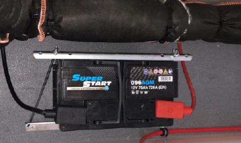
5.5.4 GENERATOR START BATTERY
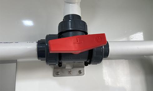
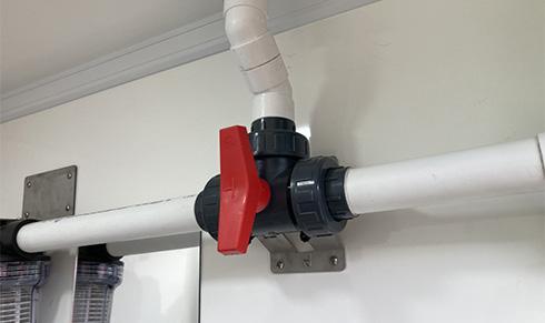
While cleaning the solar panels, especially if using water, always close the rain water valve so dirty cleaning water does not enter the fresh water tank. Locate the red valve in Drying Room or Toilet. Turn it to the correct position so water from the roof is prevented from entering the tank and instead flows through the downpipe away to the ground beneath the cabin. When finished, remember to turn the valve back to allow rain water to again enter the tank.
As well as the main Lithium Ion battery, your cabin is fitted with a secondary 145Ah battery which is used solely to start the generator. This battery is charged while the generator is running via an alternator.
This battery is located beneath the bench seating in the canteen area.
5.5.5 EMERGENCY GENERATOR RESTART
If there is ever a situation, either through user error or equipment failure, in which the battery charge level dips below the amount needed to restart the generator, it is possible to press the Emergency Generator Restart button to get the generator running again and start charging the battery. This must only be done by trained engineers.
CAUTION
The Emergency Generator Restart must only be activated by authorised and trained Engineers.
Misuse could cause damage to the unit’s lithium ion battery.
Operation & Maintenance Manual 5 – Electrical System & Equipment - Deep Green
34
INSIDE
Here
is a guide to the non-electrical features of your Deep Green welfare unit. See Manual Section 5 for a guide to all electrical features.
6
YOUR WELFARE UNIT
6.1 DRINKING WATER
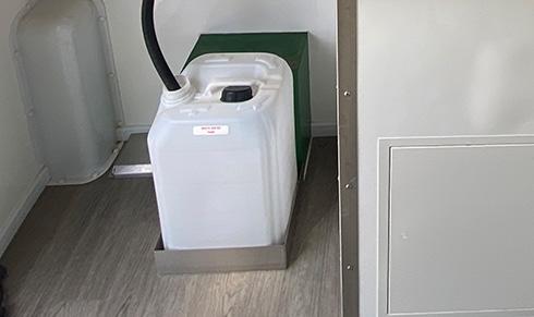
The unit is equipped with a 20l drinking water tank with a tap. This is stored in a wall bracket in the kitchen area of your canteen. During towing, the tank should be empty. To fill, lift the tank from its bracket, fill with either tap or bottled water fit for human consumption, replace the cap. Place the tank back in its bracket and secure with the strap if one is provided. The container must only be used for drinking water and must be emptied and cleaned regularly. If used for any other purpose it must be replaced.
6.2 FRESH WATER TANK

Fresh water for the Hand Wash units is stored in a tank in the base of the cabin. This is filled in two ways.
1) Via the rain water harvesting system. Rain is captured on the roof, sieved for debris and fine particles, sterilised and fed into the fresh water tank.

If there is not enough rain to keep the tank filled, it can be topped up via the black filler cap on the side of the unit door. To undo the filler cap, use the tool provided. Always fill with clean fresh water.
The fresh water tank level should be checked daily using the gauge in the Canteen.
CAUTION
The water tank weighs approx. 20kg when full. Take care while lifting. To prevent injury, use suitable lifting techniques or seek assistance when replacing.
It is essential to drain the fresh water tank of a 16ft Deep Green unit before towing. To empty the fresh water tank in either a 16ft or 12ft unit, locate the drain for the clean water tank on the underside of the trailer. Use a suitable tool to remove the drain plug from the tank Make sure the cabin is in a suitable place to allow the water to run away or use a container to catch the water then dispose of it. Replace the drain plug.
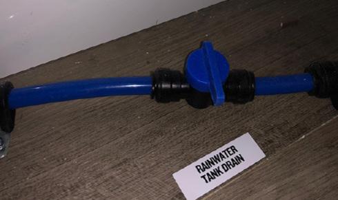
To empty the fresh water tank in a 20ft or 24ft unit, locate valve for the tank drain inside the cupboard under the desk in the Office. When you open the rainwater tank drain valve, water from the tank will run out from an outlet beneath the cabin. Make sure the cabin is in a suitable place to allow the water to run away or use a container to catch the water then dispose of it. Close the valve after emptying.
CAUTION
It is important to never let the water tank run dry as otherwise, damage may be caused to the immersion heater.
The water level can be checked using the gauge on the wall in the Canteen. The water tank level can also be checked remotely using the SOLARTrackTM system.
CAUTION
Do not attempt to tow the 16ft Deep Green unit with a full water tank as it may become unstable. Always empty the fresh water tank before towing.
NOTE
12ft, 20ft and 24ft Deep Green welfare cabins are designed so that they may be towed with a full tank of water. It is not necessary to empty the fresh water tank prior to transporting. The fresh water tank of 16ft units must be emptied before towing.
If you ever want to stop rain water entering the fresh water tank (for roof cleaning purposes etc.), locate the red rain water valve in either Drying Room or Toilet. Turn it to the correct position so water from the roof is prevented from entering the tank and instead flows through the downpipe away to the ground beneath the cabin. When finished, remember to turn the valve back to allow rain water to again enter the tank.
6.3 WASTE WATER TANK - CANTEEN
Waste water from the sink in the Canteen is drained into the waste water container beneath it. This should be emptied regularly. When you wish to empty it, remove the drain tube that runs from the sink into the tank and replace the tank cap. Lift the container from its mounting and take for disposal. Refit the empty container and ensure the drain tube from the sink is replaced in the container.
CAUTION
The Canteen waste water tank weighs approx. 25kg when full. Take care while lifting. To prevent injury, use suitable lifting techniques or seek assistance when replacing.
Operation & Maintenance Manual
6 – Inside Your Welfare Unit
36
6.4 WASTE TANK - TOILETS
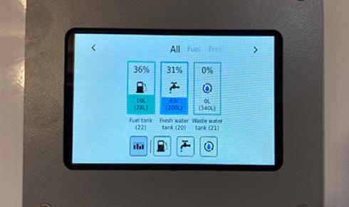
The unit is fitted with an extra-large waste tank. To check how full it is, use the gauge on the wall in the Canteen. The waste tank level can also be checked remotely using the SOLARTrackTM system. If more than 75% full, or before towing, it is essential to book a service visit to empty the tank.
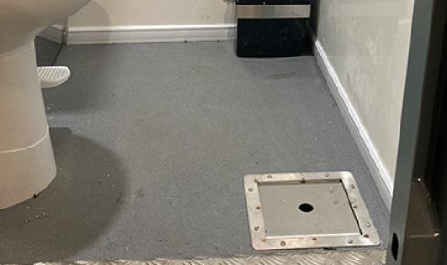
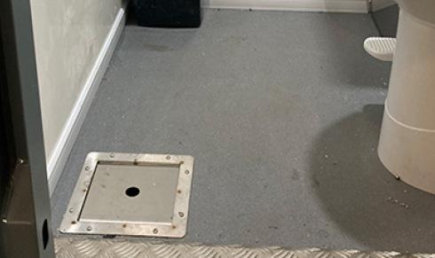
The waste water is pumped out from the point located inside the toilet compartment in the floor. Remove the cover. Connect the equipment to the drain and remove the waste. Replace the cover. If there is stubborn waste in tank, the suction hose may also be inserted into the toilet to pump out waste directly beneath.
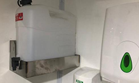
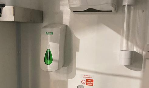
6.5 DISPENSERS
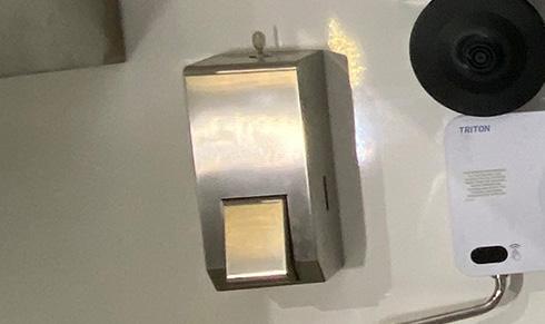
Place your hand beneath the unit and press the button to dispense soap. The soap dispenser uses 2 litre sealed pouch cartridges to minimise spillage, waste and cross- contamination. Follow the manufacturer’s instructions to replace the soap cartridges.
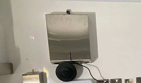
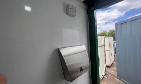
The paper towel dispenser dispenses C or Z fold towels. Place your hand beneath the unit and push the bar upwards to dispense towels. Follow the manufacturer’s instructions to replace the towels in the dispenser.
6.6 FOOD PREPARATION
To dispense cups pull the exposed part of the cup from the bottom of the dispenser. To re-fill open the top and insert cups. Please remember the environment and fill with paper cups, not plastic.
CAUTION
The waste water tank contains biological and chemical toilet waste and should only be removed by suitably trained personnel using specialist equipment. It is an offence to discharge waste into surface or domestic drainage systems.
IMPORTANT
The waste tank must always be emptied before transporting unit.
The unit’s food preparation area is supplied as standard with a kettle to make hot drinks and a microwave for hot food preparation. For information on how to power these appliances correctly accordingly to your electrical specification, see Section 5 of the manual.
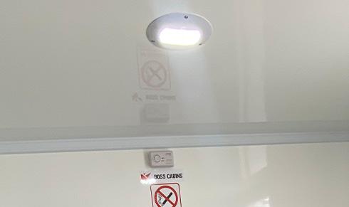
6.7 CARBON MONOXIDE ALARM

The cabin is fitted with an audible carbon monoxide alarm. If the alarm sounds, leave the unit immediately. Turn off the cabin and evacuate it. If necessary take specialist advice to determine the source of the contamination. Do not re-enter the cabin until it is safe to do so.
The monitor should be tested at regular intervals. Please refer to the Manufacturer’s Operating Manual for instructions on how to carry out these tests.
Operation & Maintenance Manual 6 – Inside Your Welfare Unit
37
6.8 BENCH SEATING
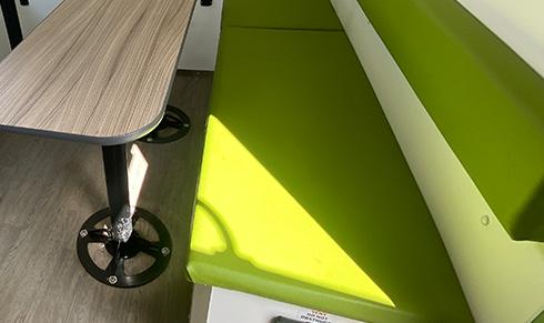
The seat pads of the bench seating in the Canteen may be cleaned by wiping down with clean water and a mild detergent. All the bench seat pads can be lifted off for deeper cleaning.
Stored within some benches is electrical equipment such as the batteries, RCD board, hydraulic ram machinery, air-blown heating ducts etc.
6.9 WINDOWS AND SHUTTERS
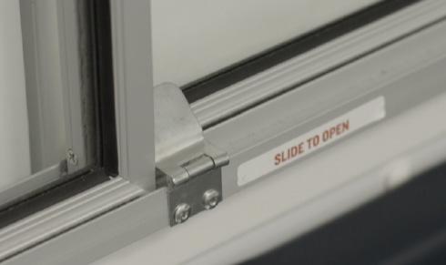
There are several sliding windows in your cabin.
To open the windows, release the latches by flipping the catch down and slide the glass panel open.
The windows are protected by steel security shutters which are locked internally and can only be opened from inside the unit. To open the shutters, flip the bottom lockbolt so it is in a downward position and flip the top one so it is in an upwards position. Then push the shutters open. There is a catch on the outside of the unit to hold them back in position.
To lock the shutters, reverse the procedure.
6.10 MAGNETIC DOOR STAYS
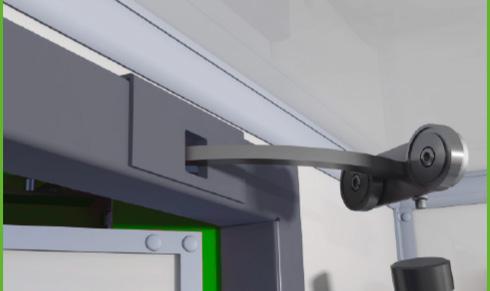
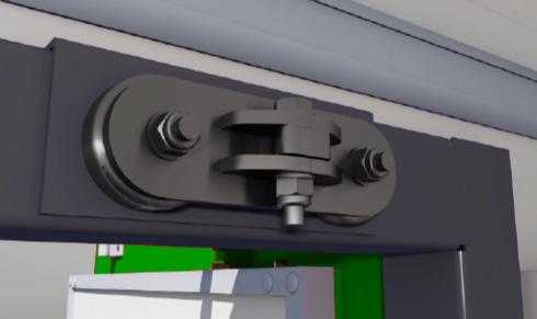
You will notice your cabin is fitted with magnetic door stays. These are robust magnetic mechanisms for holding the door open. In the fully open position, the stay will engage automatically. To close the door, disengage the mechanism simply by firmly pushing or pulling the door towards its closed position.
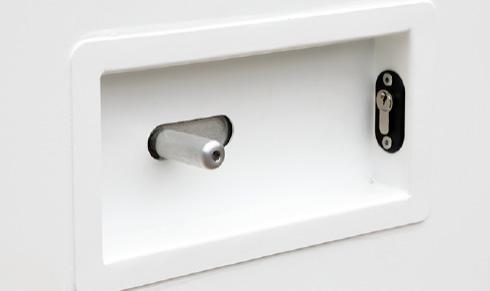
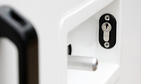
6.11 DOOR LOCKS
CAUTION
When leaving the unit unattended and when towing ensure the security shutters are closed and all windows are shut and latched.
CAUTION
The security shutter is heavy and may move suddenly if on uneven ground or when windy. Take care to avoid trap injuries to hands and fingers when opening or closing the shutters.
NOTE
Unlike traditional metal door stays where you have to remember to disengage the stay, with the magnetic stay there is no risk of damage either to the stay or to the door if the door is slammed or pulled with too much force.
CAUTION
Beware of the step when leaving the cabin.
The cabin doors are locked by moving the slider to the locked side and then locking with the key provided.
Operation & Maintenance Manual
6 – Inside Your Welfare Unit
38
USING THE FRESH WATER SYSTEM RAIN HARVESTING & WATER RECYCLING
The Deep Green unit has a fresh water system. Single or twin toilet cubicles are fitted with fresh water microflush toilets and waterless urinals with hot water hand wash units.
The patented Waste Management ProTM system harvests rain water from the roof and uses this in the hand wash units. Grey water from sinks is then recycled to flush toilets.
7
7 USING YOUR FRESH WATER SYSTEM

This welfare cabin is fitted with a unique patented Waste Management ProTM fresh water system which is designed to save water consumption in the cabin and cut waste production.
The cabin roof is designed to capture and harvest rain water [1] which is then channelled from the roof via a series of sieves and particle filters, before being delivered to the fresh water tank beneath the unit. This water is sterilised either by a UV system or by chlorine before being heated and used for hand washing in the Canteen and Toilets.
If not enough rain falls to fill the tank, it may alternatively be filled manually using any other source of fresh clean water.
The grey water recycling system reduces the amount of water needed in the cabin and cuts liquid waste. Water used in the Toilet sinks [2] is funnelled to a grey water holding tank [3] and later utilised to flush the toilets [4]
Other water-saving features are microflush toilets that use 0.5l of water per flush compared to 6l in a standard toilet and a urinal which is completely waterless.
In section 7 of the Manual, we explain how to use the Waste Management ProTM fresh water system and the cabin toilets.
7.1 RAIN HARVESTING
The roof of the cabin is designed to direct rain water to a funnelling point which channels water down into a tank in the base of the cabin.
Dependent on cabin location and weather conditions, the rain water sieve drain should be checked regularly for obstructions such as fallen leaves or other debris. Clear any obstructions immediately and dispose of them.
IMPORTANT
When washing the solar panels or roof of the cabin, the red valve must be closed to prevent dirty washing water entering the water tank. This water will then be redirected and run away to the ground beneath the cabin.
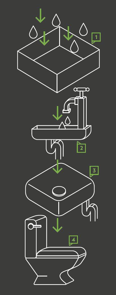
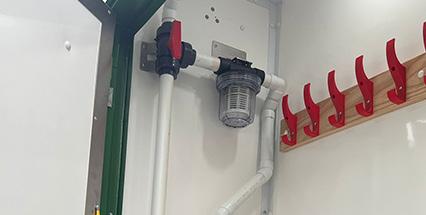
After passing through the roof sieve, rain water is directed through a fine particle filter [1] to remove any material items. This filter will either be found in the drying room or toilet cubicle. A second particle filter [2] is installed to sieve the water again when it passes out of the fresh water tank before moving through the sterilisation system. This is located under the office desk (20ft and 24ft units) or under the sink in the toilet (12ft and 16ft units). Both particle filters should be checked and washed out at regular intervals. We recommend every 6 months or earlier if any blockage is noted.
7 – Using Your Fresh Water System
1 2 40
7.2 WATER STERILISATION
Depending on the model and age of your Deep Green unit, it will have one or more of the following water sterilisation systems.
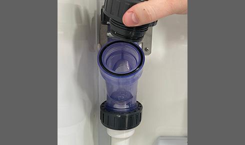
Type A - LED UV sterilisation. If your cabin is fitted with an LED UV sterilisation unit, this functions completely automatically once the Hibernation Switch in ON and you do not need to turn on an isolator. This sterilises all water passing from the fresh water tank to the hand wash units. NOTE: The bulbs in the LED unit do not need checking or changing.
Type B - Non-LED UV sterilisation. If your cabin has a non-LED sterilisation system there will be an isolator in the Office (20ft and 24ft), or it will be located under one of the benches towards the rear of the canteen (12ft and 16ft). This should be turned on at all times when water might be used. The Hibernation Switch will also need to be on. This UV unit sterilises all water passing from the fresh water tank to the hand wash units. NOTE: If the UV bulb fails, the unit will emit a beeping sound and the green light on the unit will turn off. To change the bulb, you must consult the manufacturer’s instructions. Do not open the UV unit before reading the instructions.
Type C - Chlorine sterilisation. In units fitted with a chlorine sterilisation system you will see a chlorine tab entry point. In 20ft and 24ft units, this will generally be located in the Drying Room. Otherwise, it will be in one of the toilets. The chlorine tab should be checked daily and a new tab inserted once the previous one has disappeared. Generally tabs will last an average of 6-8 weeks if rain is entering the system every day, longer if not.
Type D - Micron sterilisation filter. This sterilises water passing betweeen the fresh water tank and the hot wash units. These filters are located under the desk in the office in the 20ft and 24ft units. In the 12ft and 16ft units, they are located under the sinks in the toilets. The micron filter cartridge should be changed every 12 months. For more details, refer to the manufacturer’s instructions.
41 7 – Using Your Fresh Water System
7.3 FRESH WATER TANK
CAUTION
12ft, 20ft and 24ft Deep Green welfare cabins are designed so that they may be towed with a full tank of water so it is not necessary to empty the fresh water tank prior to transporting. However, do not attempt to tow the 16ft Deep Green unit with a full water tank as it may become unstable. Always empty the fresh water tank before towing.
SOLARTrackTM
All tank levels in Deep Green cabins can be remotely monitored by authorised users via the online SOLARTrackTM system. Contact your cabin provider to see if you have access to this system and for instructions on how to use it.
Fresh water for the hand wash units is stored in a tank in the base of the cabin. This is filled in two ways.
1) Via the rain water harvesting system.
2) The tank can also be topped up via the black filler cap on the side of the unit. To undo the filler cap, use the tool provided. Always fill with clean fresh water.
CAUTION
It is important to never let the water tank run dry as otherwise, damage may be caused to the water heater.
It is essential to drain the fresh water tank of a 16ft Deep Green unit before towing. To empty the fresh water tank in either a 16ft or 12ft unit, locate the drain for the clean water tank on the underside of the trailer. Use a suitable tool to remove the drain plug from the tank. Make sure the cabin is in a suitable place to allow the water to run away or use a container to catch the water then dispose of it. Replace the drain plug.
To empty the fresh water tank in a 20ft or 24ft unit, locate valve for the tank drain inside the cupboard under the desk in the Office. When you open the rainwater tank drain valve, water from the tank will run out from an outlet beneath the cabin. Make sure the cabin is in a suitable place to allow the water to run away or use a container to catch the water then dispose of it. Close the valve after emptying.
If you ever want to stop rain water entering the fresh water tank (for roof cleaning purposes etc.), locate the red rain water valve in either Drying Room or Toilet. Turn it to the correct position so water from the roof is prevented from entering the tank and instead flows through the downpipe away to the ground beneath the cabin. When finished, remember to turn the valve back to allow rain water to again enter the tank.
7.4 GREY WATER RECYCLING
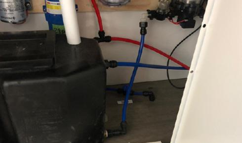
After water is used in the toilet sinks, it flows away into a grey water holding tank. It is stored there until required for flushing the toilets.
There is a grey water filter found near the grey water tank. It should be checked regularly and cleaned at 6 month intervals. The grey water tank in the 24ft unit is found in a cupboard under the desk in the office. In the 12ft and 16ft units, the grey water tank is found under the bench seat in the canteen.
7 – Using Your Fresh Water System
42
7.5 WASTE
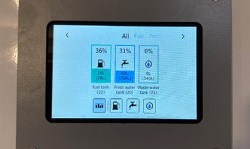
It is important to check the waste tank level in your cabin regularly. To do that, use the digital gauges located in the Canteen. If nothing is showing on the panel, make sure the Hibernation Switch is ON. The gauge panel will then light up and display Fresh Water, Waste and Fuel tank level information.
The waste tank level can also be checked remotely using the SOLARTrackTM system.
7.6 TOILET
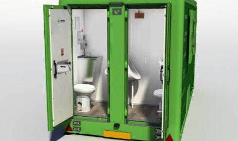
Your cabin is equipped with female and male toilet cubicles. Each contains a fresh water micro flush toilet. The male cubicle also contains a waterless urinal.
TANK AND DISPOSAL
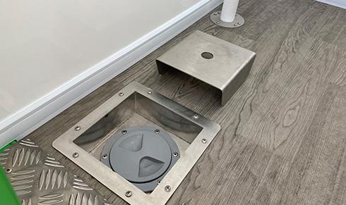
When more than 3/4 full or before towing, any waste in the waste water tank must be removed. The waste water is pumped out from the outlet located inside the toilet compartment in the floor. Remove the cover using the tool provided. Connect the equipment to the drain and remove the waste. If you experience any issues with solid waste build up in the tank, you may also insert the waste extraction pipe directly down the toilet to access solid waste below the outlet. Replace the cover.
CAUTION
The waste water tank contains biological and chemical waste from the toilet and should only be removed by suitably trained personnel using specialist equipment. It is an offence to discharge waste into surface or domestic drainage systems.
CAUTION
The unit should never be towed with water in the toilet waste reservoir as this may cause it to become unstable and overweight. Always make sure the tank is drained by a specialist company before towing the unit.
SOLARTrackTM
All tank levels in Deep Green cabins can be remotely monitored by authorised users via the online SOLARTrackTM system. Contact your cabin provider to see if you have access to this system and for instructions on how to use it.
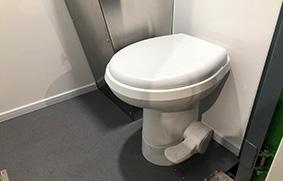
To flush after use, press down the foot pedal for a maximum of 5 seconds to clear the bowl.
NOTE: This is a MICRO FLUSH toilet designed to use significantly less water than a traditional toilet. Approx 0.5l per flush rather than 6l in a standard toilet.
7.7 HAND WASH
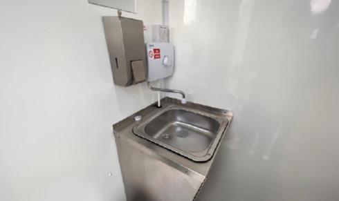
BASIN
IMPORTANT:
Only toilet paper should be flushed down this toilet. Do NOT try to flush hand towels or any other sanitary products in the toilet.
The toilet cubicles are fitted with stainless steel sink basins. Hot water for hand washing is supplied via instant hot wash units. To start the unit, simply turn the dial to the required temperature. The water is heated instantly and starts to flow. The temperature of the water can be controlled by turning the dial from 1 – Cool to 10 – Hot.
If no water comes out of the tap, check there is water in the fresh water tank. See 7.2 for how to check and fill the fresh water tank.
If the water comes out of the tap cold, check that the instant hot water unit isolator is ON. This is located just above the unit.
CAUTION
To avoid scalding set the water temperature to cool at start of use and gradually increase as required. Allow the water to run for a few seconds before use.
7 – Using Your Fresh Water System
43
7.8 HAND DRYERS
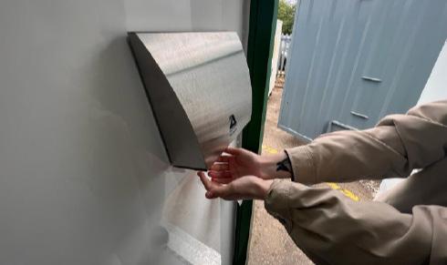
7.9 SOAP DISPENSER
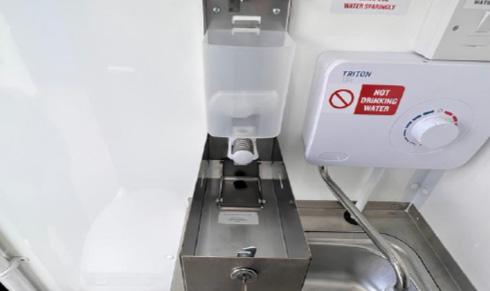
Toilet cubicles are fitted with low-power hands-free electric hand dryers for hygiene and convenience. To operate the hand dryer, simply place your hands beneath the air outlet and hot air will flow. The hand dryer isolator [1] must be in the ON position for the hand dryer to function.
The toilet cubicle is fitted as standard with soap dispensers in each toilet and in the canteen. To fill your dispensers, use the key provided to open the dispenser and drop the front down. Refill the soap container, close and relock.
7.10 TOILET DOOR LOCKS
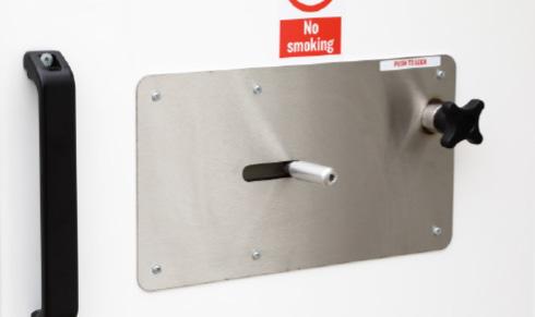
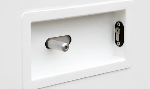
To lock the door from inside the toilet cubicle, first use the handle to close the door firmly. Next move the slider fully to the left, then push in the plunger to lock.
To unlock, pull the plunger out and move slider fully to the right. Use handle to push the door open.
There are safety locks on the toilet doors which means that as well as the usual internal lock, there is an external key-operated lock to allow access in case of an emergency.
Emergency Unlocking Procedure:
From outside the toilet cubicle, use the key to unlock the door. This will release the plunger. Move slider to the right and this will release the door.
7 – Using Your Fresh Water System
44
1
MAINTENANCE
The following section identifies items on the welfare unit that will from time to time require maintenance. Some of these can be carried out by the user, whilst others may need to be undertaken by suitably qualified and experienced technicians.
8
WARNING
• Never work beneath any unsupported load or structure.
Always move the vehicle to a safe place away from traffic or site equipment before attempting maintenance.
• Never climb on or work over or above any device without suitable fall restraint equipment.
• Ensure the unit is parked on firm level ground before changing wheels.
Always take care when working with or connecting any electrical equipment.
Damaged or inadequately insulated equipment can lead to electrocution causing fire, burns, serious injury or death.
Always follow instructions.
• If in doubt ask for assistance from suitably qualified personnel.
• Always abide by the work site’s published Safety Policy.
8.1A CHANGING A WHEELSINGLE AXLE 12FT & 16FT
If you suffer a puncture whilst towing, follow these instructions to enable you to change or repair a wheel.
8.1A.1 PREPARATION
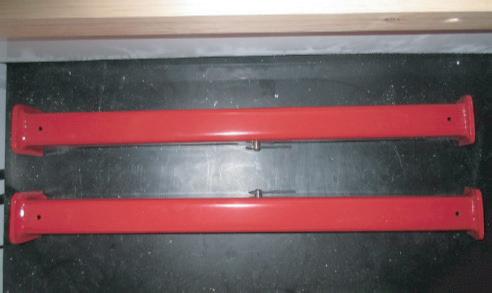
1. Make sure the unit is disconnected from the towing vehicle. Remove the hydraulic cylinder props from their stowage compartment.
8.1A.2 CHANGING THE WHEEL
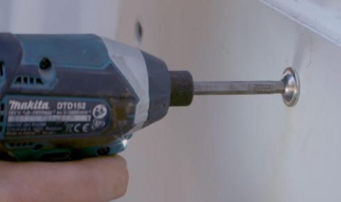
1. With the unit suitably supported, remove the screws that secure the wheel guard panel and withdraw it from the side of the cabin.

5. To refit the wheel arch, reverse the removal procedure and replace all screws.
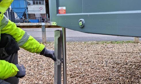
2. Raise the cabin using the lift cylinders (rams) until the wheels are clear of the ground. For instruction how to do this, go to Manual Section 3.4 and follow the first steps. Once the wheels are raised, place the cylinder props on each leg of the cabin.
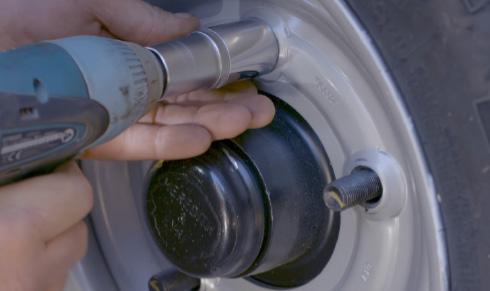
2. Loosen the wheel nuts and remove the wheel.
6. Remove the cylinder props. Use the hydraulic system to lower the cabin back onto its wheels and then replace the props and hydraulic remote control back in their stowed positions inside the cabin.

3. Secure the cylinder props using the pin and clip.
IMPORTANT
For your own safety when working underneath the cabin, you must always use one ram prop on each cylinder (ram) of your cabin.
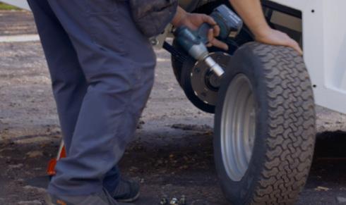
3. Repair the wheel or replace with a suitable spare.
CAUTION
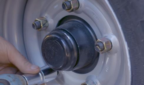
4. Refit the wheel nuts and tighten to 160Nm.
Before towing the cabin, please make sure the tyre pressure on the repaired or replaced tyre is correct. It should be 70psi.
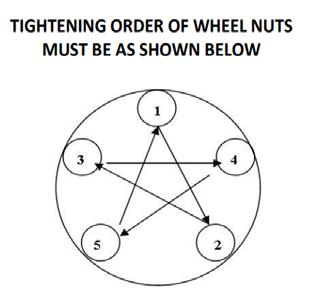
IMPORTANT
To make sure that the wheel is correctly centred, it is very important to follow the order above when tightening the wheel nuts.
Operation & Maintenance Manual
8 – Maintenance
46
8.1B CHANGING A WHEELDOUBLE AXLE 20FT & 24FT
If you suffer a puncture whilst towing, follow these instructions to enable you to change or repair a wheel.
8.1B.1 PREPARATION

1. Before changing a wheel you must make sure the unit is uncoupled from the towing vehicle. For instructions on how to do this, see Section 3.2 of this Operations Manual.
8.1B.2 CHANGING THE WHEEL

1. Use the remote control to raise the cabin up fully onto its rams. For full instructions on how to do this, see section 3.1 of this Operations Manual.
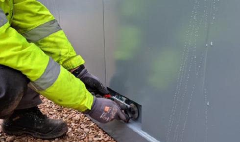
5. Use remote control to lower cabin to the ground. Again locate the two axle pins. Slide springbolt open, then push axle pin handle in fully to lock axle in place. Next slide springbolt shut making sure it covers the washer to hold the axle pin in place. Repeat for both axles.
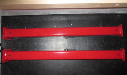
2. Locate the 4 x ram cylinder props supplied with your cabin. These MUST be used when doing any work under the cabin to ensure the safety of the staff carrying out the work.
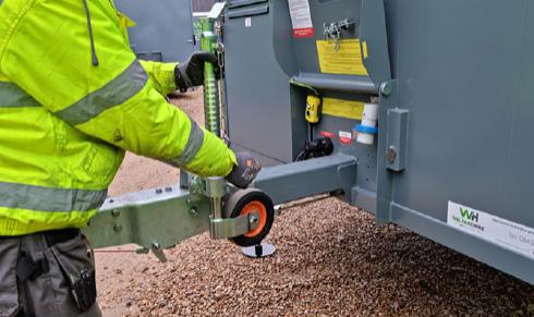
2. Raise the jockey wheel to its highest point. To do this, unscrew jockey wheel retainer [1] and lift the jockey wheel to the top. When wheel is at the top, fully tighten jockey wheel retainer.

6. Use the remote control to raise the cabin fully back up on to its rams. Then place a ram support around each of the four cylinder legs.
IMPORTANT
For your own safety when working underneath the cabin, you must always use one ram prop on each cylinder (ram) of your cabin.
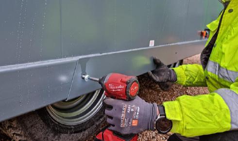
3. Remove the screws that secure the wheel arch panel and withdraw it from the side of the cabin.
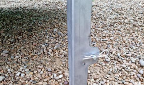
7. Secure each ram support using the pin and clip provided. Place the pin [2] through the holes to anchor the prop around the cylinder, then slide the clip [3] through the hole in the pin to secure the pin.
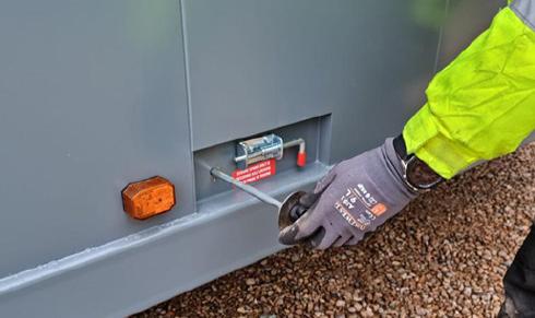
4. Locate the two axle pins on the side of the cabin. Slide the spring bolt sideways into the open position, then pull out the handle fully to release the axle locking mechanism. Slide the spring bolt shut. Repeat for both axles.
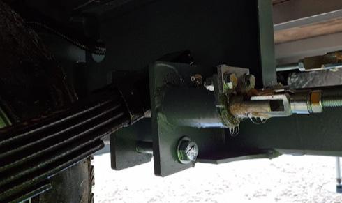
4
1
3 2
8. With the unit safely supported, go under the cabin and locate the leaf spring support bolts [4] at either end of the axle with the damaged wheel. 8 – Maintenance 47
8.1B.2 CHANGING THE WHEEL (CONTINUED)
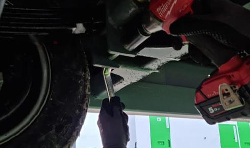
9. Unscrew the nuts and remove the bolts at either end of the axle on both left and right sides of the cabin.
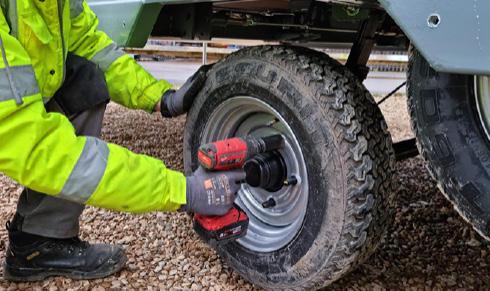
13. Loosen the wheel nuts and remove.
17. Use the remote control to raise the cabin again fully back up on to its rams. Make sure to place a ram support around each of the four cylinder legs and secure with the pins provided. .
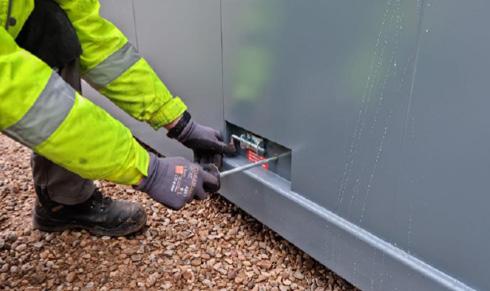
21. Remove all four ram supports and lower the cabin back to the floor. Next pull out both axle pins to release the axles.
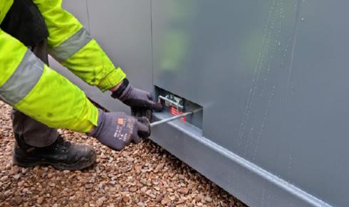
10. Remove the ram supports and lower the cabin to the ground again. Next release both axles by pulling out the axle pin handles.
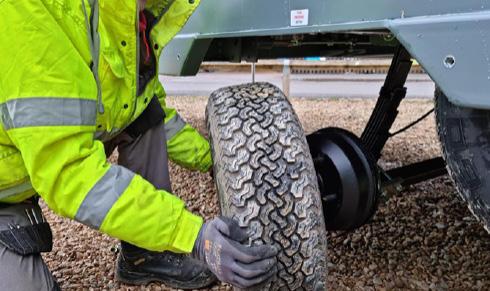
14. Remove the damaged wheel and repair or replace with a suitable spare. The correct tyre size for this unit is 185/70 R13
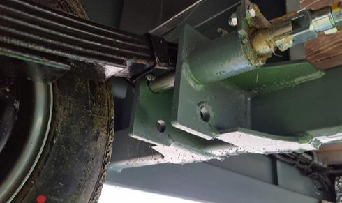
5
18. With the unit safely supported, go under the cabin and locate the holes where you previously removed the leaf spring support bolts [5]
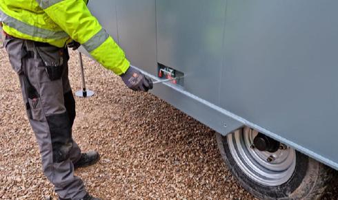
22. Use the remote control to raise the cabin back up on to its rams. Once the cabin is fully raised, push in the axle pin handles to secure the axles and cover the washers with the springbolts.
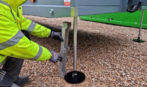
11. Raise the cabin back up onto its wheels and replace all four ram supports.
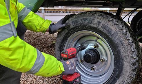
15. Tighten the wheel nuts. Check the torque settings with a torque wrench. The torque should be 160Nm on each of the wheel nuts. .
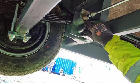
19. Replace the leaf spring support bolt at both ends of the axle and retighten the nuts. Check the torque settings with a torque wrench. The torque should be 60Nm on each of the nuts.
6
23. Unscrew the jockey wheel retainer [6] and drop jockey wheel to just above the ground. When wheel is nearly touching floor, fully tighten jockey wheel retainer.
NOTE: If you lower jockey wheel to fully touch the floor at this point, the jockey wheel may be damaged when you lower the cabin back onto its wheels.
CAUTION
Before towing the cabin, please make sure the tyre pressure on the repaired or replaced tyre is correct. It should be 87psi.
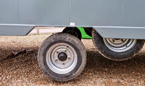
12. The axle with the wheel that needs changing should now be lowered to just above the ground..
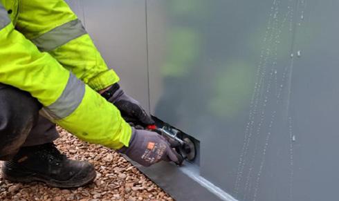
16. Lower the cabin back to the floor and slide in both axle pins to secure the axles in a raised position.
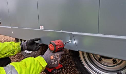
20. Replace the wheel arch cover.
24. Use the remote control to lower the cabin back onto its wheels. Check the tyre pressure is correct in the replaced tyre. It should be 87psi. You are now ready to transport your cabin.
IMPORTANT
To make sure that the wheel is correctly centred, it is very important to follow the order above when tightening the wheel nuts.
8 – Maintenance 48
8.2 BRAKE SETTING PROCEDURE –PREPARATION
1. Before setting the brakes, you must make sure the unit is uncoupled from the towing vehicle and is situated on level ground.
5. Secure each ram support using the pin and clip provided. Place the pin [1] through the holes to anchor the prop around the cylinder, then slide the clip [2] through the hole in the pin to secure the pin.
IMPORTANT
2. Locate the 4 x ram cylinder props supplied with your cabin. These MUST be used when doing any work under the cabin to ensure the safety of the staff carrying out the work.
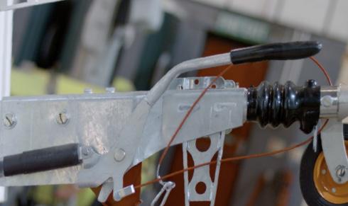
6. Lower the black handle to release the parking brake. Ensure the draw tube is fully extended out of the over run coupling.
For your own safety when working underneath the cabin, you must always use one ram prop on each cylinder (ram) of your cabin.
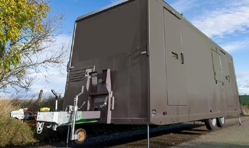
3. Use the remote control to raise the cabin up fully onto its rams. For full instructions on how to do this, see section .3.1 of this Operations Manual.

7. Check that the brake cables [3] are not under tension. If necessary reduce tension by adjusting the M8 nuts [4] at the ends of the cables on the cable compensator bar [5]
CAUTION
Make sure the unit is on level ground to carry out this procedure.
4. Place a ram support around each cylinder leg. There is one on each corner of the cabin..
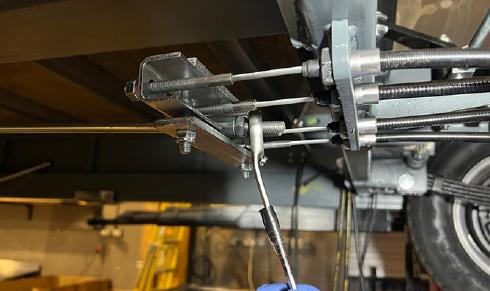
8. Check that the brake rod [6] is not under tension. If necessary reduce the tension by adjusting the M10 lock nut [7] at the end of the rod on the cable compensator bar.
Operation & Maintenance Manual 8 – Maintenance
7 6
2 1
3 4 5 49
8.2A BRAKE SETTING PROCEDURESINGLE AXLE
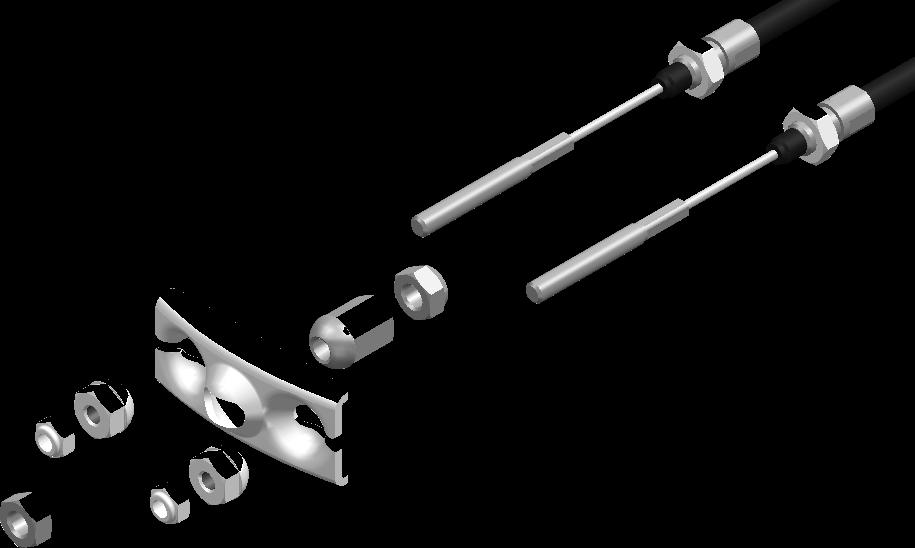
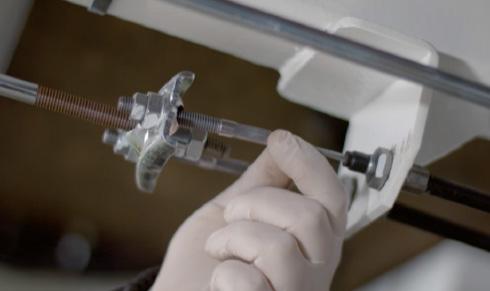
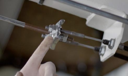
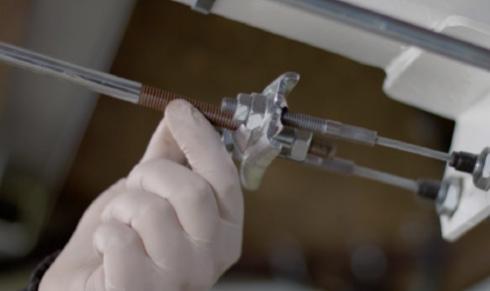
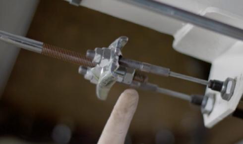
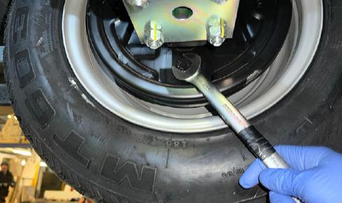

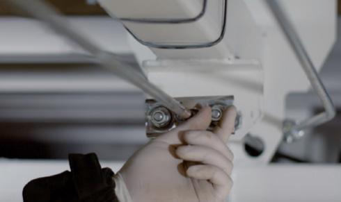
Operation & Maintenance Manual 8 – Maintenance
1. Brake cable outer locknut
2. Brake cable spherical nut
3. Brake cable compensator bar
4. Brake rod spherical nut
5. Brake rod outer locknut
6. Brake cable
1. Check that the brake cables are not under tension, if necessary reduce this tension by adjusting the spherical nuts at the ends of the cables on the cable compensator bar.
2. Check that the brake rod is not under tension, if necessary reduce the tension by adjusting the spherical nuts at the end of the rod on the cable compensator bar.
4. Next set the Cable Compensator Bar [1]. This bar must be aligned perpendicular (90º) to the direction of travel. Once in position, secure the position using the M8 nuts [2] at the ends of the brake cables.
3. To set the wheel brakes, tighten the adjusting screw on the rear of the brake unit back plate clockwise until it is not possible to turn the wheel by hand. When rotating the wheel, it is very important to ONLY move the wheel in a FORWARDS motion as shown by the red arrow in the photo. Next, turn the adjusting screw back (counter clockwise) by approx 1/2 a turn (180 deg) or until the wheel turns freely by hand. Again, when checking wheel movement, only rotate in a forwards direction. Slight rubbing noises which do not impede the motion of the wheel are normal. Repeat this process for each wheel.
1 2 3 4 6 5 4 1 2 3 50
5. Next set the Brake Rod [3]. Adjust the brake rod by tightening or loosening the adjusting spherical nut [4] until there is neither tension or free play in it. Once the spherical nut is holding the brake rod correctly, then tighten the outer lock nut onto the spherical nut to secure.
8.2A BRAKE SETTING PROCEDURE - SINGLE AXLE (CONTINUED)
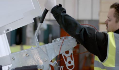
6. Finally set the Parking Brake Lever. Firmly activate the handbrake repeatedly in order to re-seat the braking components. When applying the handbrake lever do not force it further back than its normal rest position.
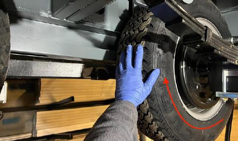
10. Finally, rotate the wheels again in a forwards direction to check they move freely without the brake pads rubbing.
7. Check the orientation of the Cable Compensator Bar beneath the cabin again, making sure that it remains in position, perpendicular to the direction of travel.
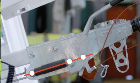
8. Move handbrake lever so that all three pivots are in line as shown by the red line in this image. With the brake set in this position, the brake reaction lever [5] should just be contact with the handbrake lever.
WARNING
If at any point during the brake setting process, the wheels are rotated in the reverse direction, there is a danger of the autoreverse mechanism being activated. If this is the case or the brakes do not operate correctly, check for faults and repeat the whole procedure again from step 1.
CAUTION
During brake setting, ONLY rotate the wheels in a forward direction. Also do not use the brake rod as a means of adjusting the brakes.
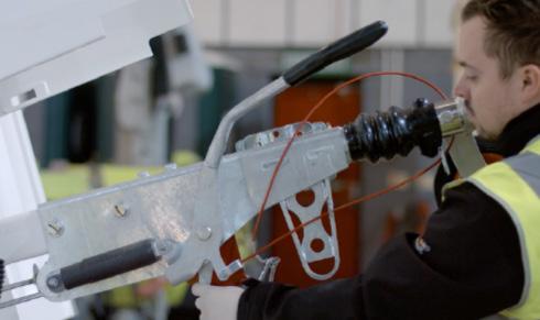
9. Check that the brake reaction lever is in contact with the handbrake lever and has 10–15mm of movement away from the handbrake lever when it is pushed manually.
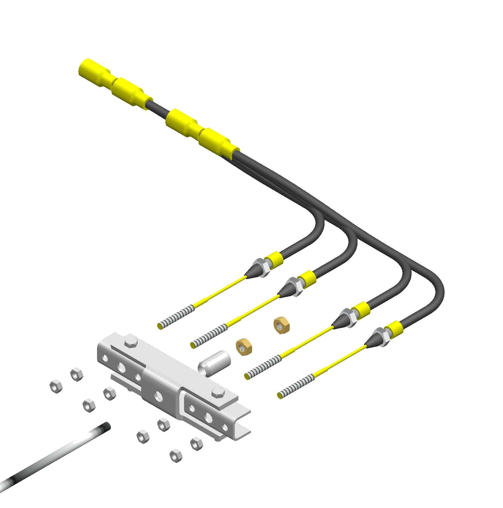
NOTE
Some slight “grinding noises” which do not impede the movement may be heard, this is normal.
8 – Maintenance 51
1 5 2 6 7 3 4
5
8.2B BRAKE SETTING PROCEDURE - DOUBLE AXLE (CONTINUED)
1. To set the wheel brakes, tighten the adjusting screw on the rear of the brake unit back plate clockwise until it is not possible to turn the wheel by hand. When rotating the wheel, it is very important to ONLY move the wheel in a FORWARDS motion as shown by the red arrow in the photo. Next, turn the adjusting screw back (counter clockwise) by approx 1/2 a turn (180 deg) or until the wheel turns freely by hand. Again, when checking wheel movement, only rotate in a forwards direction. Slight rubbing noises which do not impede the motion of the wheel are normal. Repeat this process for each wheel.
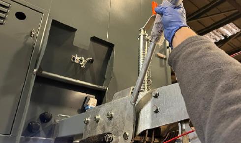
4. Activate the handbrake at least 5 times in order to re-seat the braking components. When applying the handbrake lever do not force it further back than its normal rest position.
8. Finally, rotate the wheels again in a forwards direction to check they move freely without the brake pads rubbing.
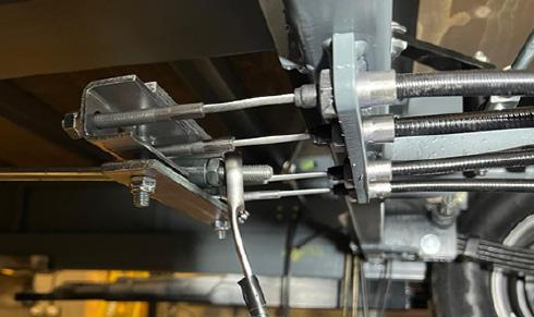
5. Check the orientation of the Cable Compensator Bar beneath the cabin again, making sure that it remains in position, perpendicular to the direction of travel. If it has moved during the brake reseating process, adjust it so it sits perpendicular again.
WARNING
If at any point during the brake setting process, the wheels are rotated in the reverse direction, there is a danger of the autoreverse mechanism being activated. If this is the case or the brakes do not operate correctly, check for faults and repeat the whole procedure again from step 1.
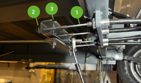
2. Next set the Cable Compensator Bar [1]. This bar must be aligned perpendicular (90º) to the direction of travel. Once in position, secure the position using the M8 nuts [2] at the ends of the brake cables [3]
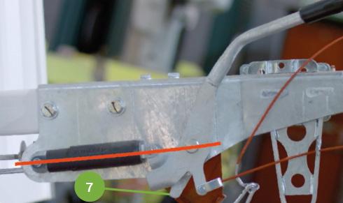
6. Move handbrake lever so that all three pivots are in line as shown by the red line in this image. With the brake set in this position, the brake reaction lever [6] should just be contact with the handbrake lever.
CAUTION
During brake setting, ONLY rotate the wheels in a forward direction. Also do not use the brake rod as a means of adjusting the brakes.
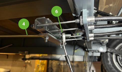
3. Set up the Brake Rod [4] so there is neither play nor tension in it by adjusting at the Brake Cable Compensator Bar. When correctly adjusted, tighten the M10 lock nuts [5] at the end of the brake rod.
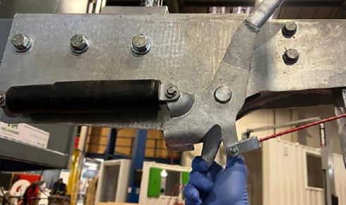
7. Pull the brake reaction lever back away from the handbrake lever manually and there should be more or less 10mm of movement away from the handbrake lever. If there is too much or too little movement, you will need to adjust the nuts on the cable compensator bar again.
NOTE
Some slight “grinding noises” which do not impede the movement may be heard, this is normal.
8 – Maintenance 52
2 1 3 4 5 6
8.3 BRAKE CHECK AND TEST
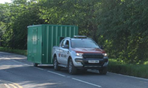
CAUTION
Ensure that any testing carried out on public or private roads is done taking due account of other road users.
NOTE
All braking should be gradual and sympathetic to the system. Aggressive and violent braking should be avoided during these procedures in order to safely judge the braking performance and obtain optimum bedding in of the brake linings.
BEDDING IN THE BRAKES
ROAD TEST A
1. Drive in a straight line at 20/25 mph; apply the brakes gradually and firmly to produce a smooth stop.
2. Observe the behaviour of the cabin during braking (this may be more easily done by a passenger in the towing vehicle rather than the driver).
3. If the cabin is pulling to one side under braking or the wheels are locking up on one side, the system MUST be checked and reset before proceeding. Once smooth straight line braking is achieved at this speed, proceed to Road Test B.
ROAD TEST B
1. Drive in a straight line at 35/40mph (assuming speed limits allow) and apply the brakes firmly and steadily without locking up the trailer wheels.
2. Once again observe the behaviour and handling of the cabin under braking and, as in Road Test A, readjust the system if braking is not even on both sides.
ROAD TEST C
1. Finally drive at 50mph (if speed limits allow) and apply the brakes to reduce speed to 30mph, accelerating back to 50mph.
2. If satisfied that the cabin is braking evenly and steadily, repeat the manoeuvre 3 or 4 times.
The brake linings will wear in, improving in performance as they take on the contours of the drum. They will also generate heat which in turn will optimise the coefficient of friction on the linings and provide improved braking performance as they “bed in”. Dependent on the type of driving style used, the brakes may not achieve optimum efficiency either in overrun or on the brake lever for 500 miles. Stop/start driving will bed the brakes in more quickly than motorway driving where the brakes are hardly used.
In the event of the shoes adhering to the drum it will be necessary to release them using the following procedure:
1) Turn the adjuster bolt anticlockwise by approximately half a turn.
2) Tap the bottom of the back plate using a soft faced or wooden mallet.
3) If the brake shoes have not released, jack up the trailer as described earlier in this manual.
4) Remove wheel assembly.
5) Tap brake drum with mallet.
6) Once the brake shoes have released, readjust the brake.
IMPORTANT
During the bedding in process the properties at the surface of the lining change. Until the brakes are bedded in according to this recommended procedure there is a possibility that the brake shoes may adhere to the brake drum surface when parked with the handbrake lever in the “on” position.
Since the introduction of asbestos-free brake linings this has been found to occur with ALL makes of lining material. It is therefore recommended that, if the cabin is to be parked for extended periods or in damp or humid conditions, the wheels are chocked and handbrake lever released.
In addition, it is also good practice, if reversing the cabin into position, to draw the cabin forward slightly before leaving. This ensures that the brake shoes have returned to their normal running position.
Please note that there may be corrosion within the drum that has been a contributory factor to the brake linings sticking. It is recommended as good practice to therefore remove the drums and clean them before the cabin is once again parked. Frequent use of the overrun brakes should ensure that the drum surface remains free of corrosion.
Brakes should be readjusted as often as is necessary. There is no set time or distance limit. Users should check the slack in the system before each journey and readjust accordingly. Most couplings have 90 or 100mm of travel through the drawtube (connecting rod) and damper. The simplest way to check the slack on most systems is to push the bottom of the brake reaction lever forward and if the movement is more than half of the coupling travel, i.e. 45 or 50mm, it is recommended that the brakes are readjusted.
A service should also be performed on the braking system at regular intervals. The timing of this may depend on the use of the cabin, in terms of distance and driving style.
Cabins that are for occasional use only should also be checked to ensure that no parts have seized. During these service checks the drums should be removed and the brakes checked for damage and wear. Linings should be replaced if there is less than 2mm lining thickness left on the shoe. This should ensure that the linings do not wear out before the next service.
Operation & Maintenance Manual
8 – Maintenance
53
Operation & Maintenance Manual 8.4 SERVICE CHECKS Daily Weekly Monthly 6 months Annual Before transporting Before use on arrival to site Manual section Check and fill drinking water container (canteen) or empty if transporting X X X 6.1 Check and remove waste water (canteen) X X 6.3 Replenish water cups X X 6.5 Check and fill dispensers – hand towels, soap X X 6.5 Check and refill generator fuel level X X 4.3 Check generator engine oil level X X 4.3 Check and fill fresh water tank X X X 7.3 Check and clean rain water particle filter X X X 7.1 Check and clean particle filter at exit from fresh water tank X Check and clean grey water filter X X X 7.4 Replace micron sterilisation cartridge (if applicable) X Check and clean rain water drain on roof X X X 7.1 Check bulb in UV sterilisation unit (non-LED version only) X Clean solar panels X X X 5.5 Check CO monitor function X X 6.7 Check CO monitor sensor X X 6.7 Check electrical system function (RCD board) X X 8.5 Check security of door and window locks X X X 6.11 Check operation of anti vandal cover X X Check for wear in drawbar coupling X Remove internal door panels and grease moving parts of door locking mechanisms X Check for corrosion and mechanical defects in braking system X Check tyre inflation X X 8.1 Grease the axle locking pins and towing coupler X X Check brake setting/operation X X 8.2 Check brake function X X 8.3 Check tyre condition X X Check coupler function X X Check function of all lights X X Check breakaway cable function X X Grease bright metal and other exposed parts X X NOTE: An annual safety checking service is available from Boss Cabins Ltd. Contact the manufacturer or their agent for more information. 8 – Maintenance Generator Service Intervals RedBox Infinity 2000 hours 54
8.5 ELECTRICAL CHECKS
In order to ensure correct function of the electrical system of your cabin and the safety of all operatives, there are certain electrical checks that should be carried out.
Some of these can be undertaken by the users, whilst others may need to be undertaken by qualified and suitably experienced technicians.
• Always take care when working with or connecting any electrical equipment. Damaged or inadequately insulated equipment can lead to electrocution causing fire, burns, serious injury or death.
8.5.1 FUSE BOX CHECK
Depending on the model and age of your Deep green cabin, it will have one of these two types of RCD board.
TYPE A - In most Deep Green units, the RCD board will be located on the wall in the Canteen or the Office. It will contain a RCD Main switch and Test button, and individual MCBs to protect the electrical circuits for the vehicle.
According to BS7671 IET Wiring Regulations 18th Edition, the fuse box in your cabin should be tested every six months.
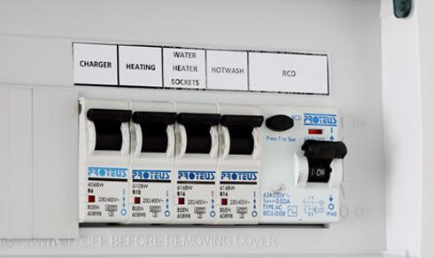
To test the Main RCD open the cover and ensure the RCD paddle [1] is in the up “ON” position. Press the TEST button [2], the paddle will move to the down “OFF” position and power will be cut to all circuits. If this does not happen, the RCD is faulty and the electrical system should not be used until rectified by qualified personnel. To reset the RCD or any MCB push the paddles to the “ON” position.
• Always follow instructions. If in doubt, ask for assistance from suitably qualified personnel.
• Always abide by the work site’s published Safety Policy.
TYPE B - In units with an RCD board integrated to the solar system, you will find the distribution board located in the right hand bench seat int the Canteen of the welfare unit. It contains an RCD Main Power Outlet switch, an orange Test button, and individual MCBs to protect the electrical circuits for the cabin.
To test the operation of residual current devices (RCDs/RCBOs) fitted in the cabin, first check that the RCD Main Power Outlet paddle [3] is in the ON position. Press the orange TEST button [4] .The Main Power Outlet paddle should flip down to the OFF position and power will be cut to all circuits. If this does not happen, the RCD is faulty and the electrical system should not be used until rectified by qualified personnel. To reset the RCD or any MCB push the paddles to the ON position.
NOTE
The RCD board function should always be checked when a unit is delivered to site. It should also be checked periodically every six months even if the cabin has not been moved.
Operation & Maintenance Manual
WARNING 8 – Maintenance 3
4
1 2 55
DIAGNOSTICS
9
9 DIAGNOSTICS DEEP GREEN
Here we highlight a few issues you may encounter while using your cabin and give solutions on how to remedy them.
If at any point you have any questions or doubts, please do not hesitate to contact our Service Department.
REFERENCES
While carrying out diagnostics on your cabin, you may need to refer to:
Your RedBox Infinity generator is located in the compartment on the front of cabin. Key features are:
1. Exhaust outlet
2. Canister secondary fuel filter
3. Oil filter
4. Oil filler hole (orange cap)
5. Oil min/max gauges located on extended sump
6. Fuel filter
GENERATOR CONTROL PANEL
The main generator control panel is located in the Canteen on the wall under the sink. This contains:
1. An RCD panel
2. The DSE generator control device
3. Fuel pump prime button
4. The blue generator alarm reset button
5. Circuit breakers for the 12V DC 2A and 20A systems and for the 220V AC 1 A system
WARNING
• Never work beneath any unsupported load or structure.
To contact Boss Cabins Service Department, call 01778 300475 or email aftercare@bosscabins.co.uk
• Always move the vehicle to a safe place away from traffic or site equipment before attempting maintenance.
• Never climb on or work over or above any device without suitable fall restraint equipment.
Ensure the unit is parked on firm level ground before changing wheels.
Always take care when working with or connecting any electrical equipment. Damaged or inadequately insulated equipment can lead to electrocution causing fire, burns, serious injury or death.
Always follow instructions.
• If in doubt ask for assistance from suitably qualified personnel.
• Always abide by the work site’s published Safety Policy.
1 2 3 4
REDBOX INFINITY GENERATOR 5 1 3 5 6 4 2
57
9.1 NO ELECTRICITY IN CABIN
9.1.1 CHECK HIBERNATION SWITCH IN CANTEEN – IS IT ON?
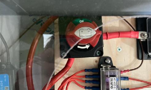
YES – Go to Point 9.1.2.
NO – Turn Hibernation Switch on.
Is there electrical supply now?
YES – CONGRATULATIONS!
NO – Go to point 9.1.2.
9.1.2 ON THE GENERATOR CONTROL PANEL, IS THE GENERATOR EMERGENCY STOP BUTTON PUSHED IN?
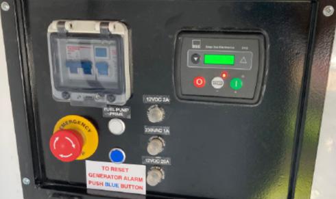
NO – Go to point 9.1.3.
YES – Twist the E-Stop button clockwise to release and it will pop out. Next press the blue button to reset the generator. If there is insufficient battery, the generator can now start up to power the cabin and recharge the battery.
Does generator start now and have the electrics started to work?
YES – CONGRATULATIONS!
NO – Go to point 9.1.3.
9.1.3 IS THERE SUFFICIENT FUEL IN THE TANK TO ALLOW THE GENERATOR TO START?
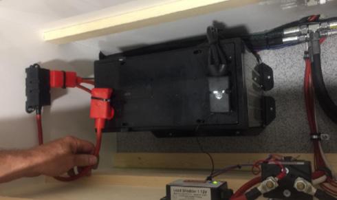
Check the manual fuel gauge near the filler cap either in the fuel compartment (20ft) or on the side of the cabin (24ft). The cabin owner can also check the fuel remotely using the SOLARTrackTM system. Is there fuel in the tank?
YES – Go to Point 9.1.4.
NO – Fill the tank with suitable fuel - HVO biofuel or diesel. Do not use bio diesel. Press the Fuel Pump Prime button on the Generator Control Panel for 5-10 seconds to send fuel to the engine. You can try this more than once if it does not work first time.
Does generator start now and are the electrics running?
YES – CONGRATULATIONS!
NO – Go to Point 9.1.4.
Fuel Pump Prime button
9.1.4 CHECK CABLES ON GENERATOR START BATTERY – ARE THEY SECURE?
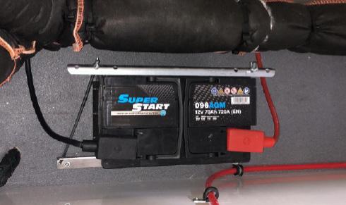
The generator start battery is found in the Canteen bench. Check the cables connected to it - are they secure?
YES – Go to point 9.1.5.
NO – Tighten the cables.
Does generator start now and are the electrics running?
YES – CONGRATULATIONS!
NO – Go to point 9.1.5.
Operation & Maintenance Manual 9 – Diagnostics – Deep Green
Emergency Stop button
58
9.1.5 CHECK THE GENERATOR START BATTERY VOLTAGE ON THE DSE PANEL ON THE GENERATOR CONTROL PANEL
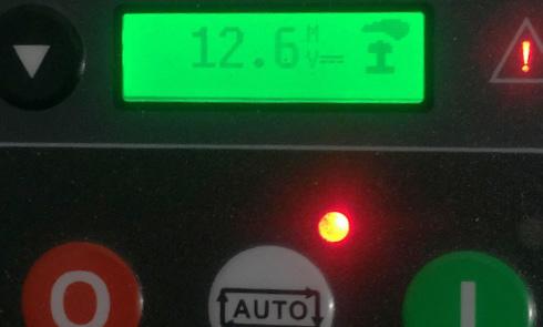
Press four times until you reach the Battery Voltage display. Is the battery voltage showing as <12.2?
NO – Go to point 9.1.6.
YES – Plug in an external power source. Make sure Internal/External Power switch is in position for external power. The battery should now charge. If no external power source is available, remove and charge the battery for 1 hour. Is battery voltage now showing as >12.2?
NO – Replace the battery with a new one.
Once battery is charged or replaced and voltage is showing as >12.2, does generator start now?
YES – CONGRATULATIONS!
NO – Go to point 9.1.6.
9.1.6 CHECK STARTER MOTOR CABLES AT REAR OF ENGINE INSIDE GENERATOR – ARE THEY SECURE?
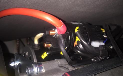
YES – Go to point 9.1.7.
NO – Tighten the cables.
Does generator start now and is there electrics in the cabin?
YES – CONGRATULATIONS!
NO – Go to point 9.1.7.
9.1.7 USE EMERGENCY GENERATOR RESTART BUTTON.
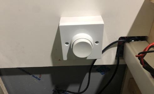
CAUTION: THIS STEP MUST ONLY BE CARRIED OUT BY AUTHORISED PERSONNEL. CALL BOSS CABINS’ SERVICE DEPARTMENT TO ARRANGE FOR A SERVICE ENGINEER TO ATTEND SITE.
The pneumatic emegency generator restart button is located inside the bench on the door side of the Canteen. If there is ever a situation, either through user error or equipment failure, in which the battery charge level dips below the amount needed to restart the generator, it is possible to press this Emergency Generator Restart button to get the generator running again and start charging the battery.
Operation & Maintenance Manual To contact Boss Cabins, call 01778 300475 or email info@bosscabins.co.uk 9 – Diagnostics – Deep Green
59
9.2 GENERATOR ISSUES
If you have any problems with your back up generator, first Check DSE display on the Generator Control Panel in the Canteen to see what if any error symbols are showing.
9.2.1 IF DSE DISPLAY SHOWS: E STOP SYMBOL
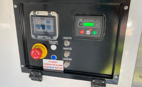
If E-STOP is OUT – Contact Boss Cabins Service Department.
If E-STOP is IN – Release the E-STOP by twisting it clockwise. Press blue RESET button on generator.
Does generator start now?
YES – CONGRATULATIONS!
NO – Contact Boss Cabins Service Department.
9.2.2 IF DSE DISPLAY SHOWS FUEL SYMBOL
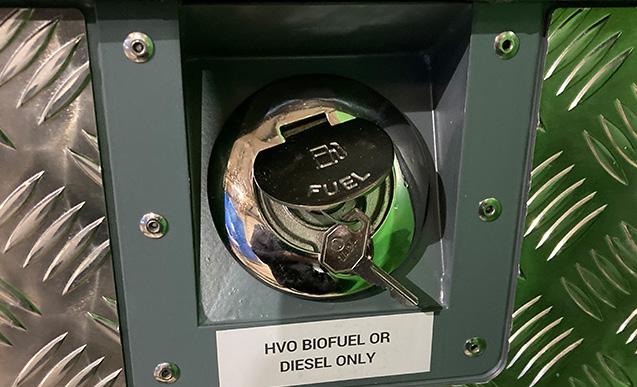
Top up with fuel. Use HVO biofuel or diesel only. Do not use bio diesel. Press blue RESET button on generator and press the Fuel Pump Prime button if necessary.
Does generator start now?
YES – CONGRATULATIONS!
NO – Contact Boss Cabins Service Department.
9.2.3 IF DSE DISPLAY SHOWS: LOW V LOW HZ ICONS (FLASHING ALTERNATELY)
a) Check fuel filters – are they dirty?
NO – See b) below. YES – Replace filters.
Press blue RESET button on generator. Does generator start and continue running now?
YES – CONGRATULATIONS! NO – See b) below
b) Check fuel feed pipes / fuel tank for blockage – are they blocked?
NO – See c) below YES – Clear blockage
Press blue RESET button on generator. Does generator start and continue running now?
YES – CONGRATULATIONS! NO – See c) below
c) Check fuel quality – is the correct specified fuel being used?
YES – Contact Boss Cabins Service Department.
NO – Change fuel to correctly specified quality fuel.
Press blue RESET button on generator. Does generator start and continue running now?
YES – CONGRATULATIONS!
NO – Contact Boss Cabins Service Department
Operation & Maintenance Manual
9 – Diagnostics – Deep Green
To contact Boss Cabins, call 01778 300475 or email info@bosscabins.co.uk 60
9.2.4 IF DSE DISPLAY SHOWS: V
Press blue RESET button on generator.
Press once on DSE control panel and check generator voltage.
Are the volts showing as >259?
YES – Adjust idle speed to 3100 +10/-30.
Recheck the voltage.
Is it within accepted parameters (check RedBox manual for parameters)?
Does generator start and continue running now?
YES – CONGRATULATIONS!
NO – Contact Boss Cabins Service Department.
9.2.5 IF DSE DISPLAY SHOWS:V
Press blue RESET button on generator.
Press once on the DSE panel and check generator voltage.
Are the volts showing as <190?
YES – Adjust idle speed to 3100 +10/-30.
Recheck voltage – is it correct?
NO – Contact Boss Cabins Service Department.
YES – Does generator start and continue running now?
YES – CONGRATULATIONS!
NO – Contact Boss Cabins Service Department.
9.2.6 IF DSE DISPLAY SHOWS: OIL CAN
Check oil level in generator. For instruction on how to do this, go to Manual Section 4.3.
Is the oil level correct?
YES – Contact Boss Cabins Service Department.
NO – Top up the oil as described in Section 4.3 of the Operations Manual.
Press blue RESET button on generator.Does generator start and continue running now?
YES – CONGRATULATIONS!
NO – Contact Boss Cabins Service Department.
Operation & Maintenance Manual
9 – Diagnostics – Deep Green To contact Boss Cabins, call 01778 300475 or email info@bosscabins.co.uk 61
9.3 NO 230V POWER TO CABIN
9.3.1 IS IT JUST THE KETTLE OR MICROWAVE AFFECTED?

NO – Go to 9.3.2.
YES – To save energy, the kettle and microwave must be used individually. Power is directed to one or the other using the Kettle/Microwave Selector Switch. Make sure this is in the correct position for the appliance you wish to use. Do the kettle and microwave work correctly now?
YES – CONGRATULATIONS!
NO – Go to 9.3.2.
9.3.2 HAVE YOU CHECKED THE INDIVIDUAL APPLIANCE ISOLATORS?
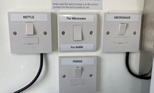
YES – If all isolator switches are already on, go to 9.3.3.
NO – A number of electrical items in the cabin have individual isolator switches which must be on for the to operate - kettle, microwave, water heaters, electric hand dryers and in some models UV sterilisation system. Make sure all these are switched on.
Do the electrical items work now?
YES – CONGRATULATIONS!
NO – Go to 9.3.3.
9.3.3 CHECK BREAKER SWITCH UNDER THE FLAP ON THE GENERATOR CONTROL PANEL – IS IT ON?
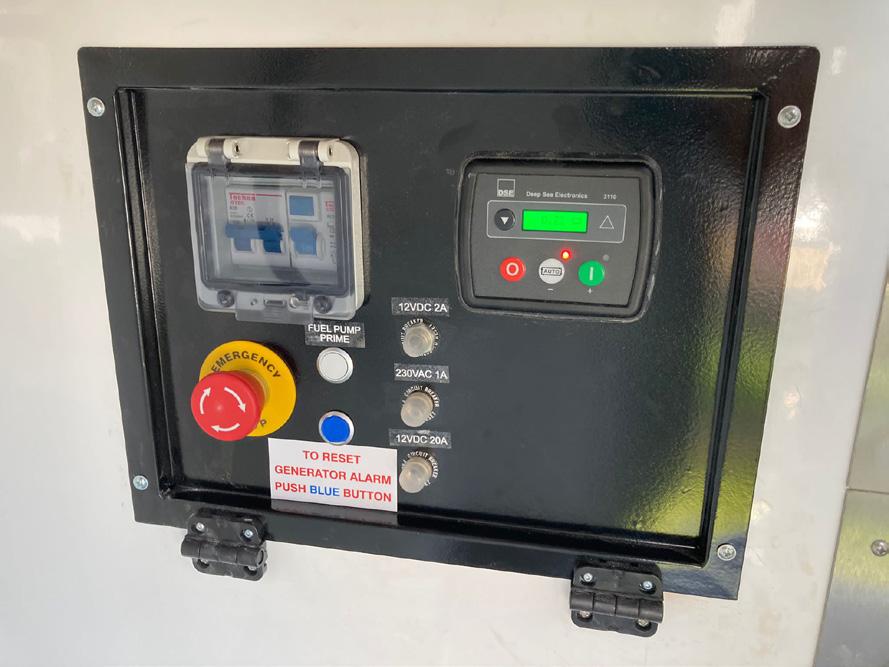
YES – Go to 9.3.4.
NO – Turn it on
Is there 230V power now?
YES – CONGRATULATIONS!
NO – Go to 9.3.4.
Breaker switch
Operation & Maintenance Manual
9 – Diagnostics – Deep Green
To contact Boss Cabins, call 01778 300475 or email info@bosscabins.co.uk 62
9.3.4 CHECK THE INTERNAL/EXTERNAL POWER SWITCH INSIDE THE BENCH IN THE CANTEEN – IS IT IN THE CORRECT POSITION FOR INTERNAL POWER?
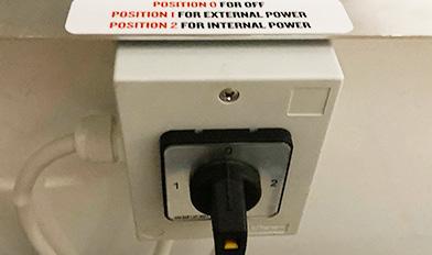
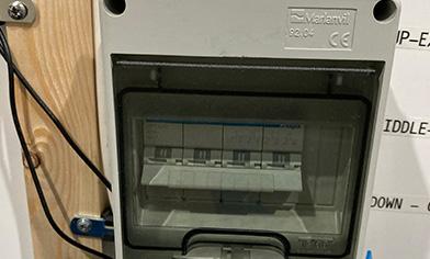
YES – Go to 9.3.5.
NO – Turn switch to the correct position for INTERNAL POWER
Is there 230V power now?
YES – CONGRATULATIONS!
NO – Go to 9.3.5.
NOTE
You may have one of two types of Internal/External Power Selector switch in your cabin.
Type A positions are:
0 - OFF
1 - External power source
2 - Internal solar, battery or generator power.
Type B positions are:
0 (centre) - OFF,
I (up) - Internal solar, battery or generator power
II (down) - External power source.
9.3.5 CHECK SWITCHES ON RCD BOARD ARE ON (UP POSITION) –ARE THEY ON?
YES – Contact Boss Cabins.
NO – Make sure all the RCD paddle switches are ON (up position).
Is there 230V power now?
YES – CONGRATULATIONS!
NO – Contact Boss Cabins.
Main Power Outlet Switch
Operation & Maintenance Manual
9 – Diagnostics – Deep Green
To contact Boss Cabins, call 01778 300475 or email info@bosscabins.co.uk B A 63
9.4 NO
24V POWER IN CABIN
9.4.1
CHECK
HIBERNATION SWITCH IN CANTEEN – IS IT ON?
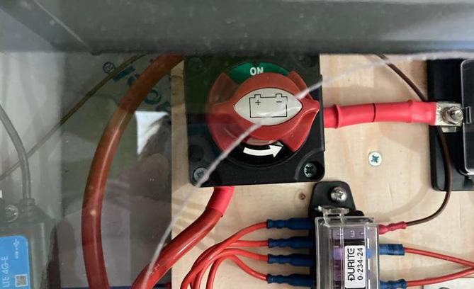
YES – Follow the steps in 9.1 to try to get electrics working.
NO – Turn Hibernation switch on.
Do the 24V electrics work now?
YES – CONGRATULATIONS!
NO – Are any electrics working?
YES – Contact Boss Cabins Service Department.
NO – Follow the steps in 9.1 to try to get electrics working.
9.5 ELECTRIC HYDRAULIC SYSTEM NOT WORKING – NO POWER TO RAMS
9.5.1 CHECK HIBERNATION SWITCH IN THE CANTEEN – IS IT IN ON POSITION?
YES – Check cabin electrics using Section 9.1.
NO – Turn on the Hibernation Switch.
Do the electric rams operate now?
YES – CONGRATULATIONS!
NO – Check cabin electrics using Section 9.1.
Operation & Maintenance Manual
9 – Diagnostics – Deep Green
To contact Boss Cabins, call 01778 300475 or email info@bosscabins.co.uk 64
9.6 WATER HEATER NOT WORKING
Is there water coming out of the taps? If no water is coming out, go to 9.6.3. If there is water coming out but it is cold, go to 9.6.1.
9.6.1 IS THE HIBERNATION SWITCH ON?
YES – Go to 9.6.2.
NO – Turn Hibernation switch on. Is the water hot now?
YES – CONGRATULATIONS!
NO – Go to 9.6.2.
9.6.2 ARE THE INSTANT WATER HEATER ISOLATORS ON?
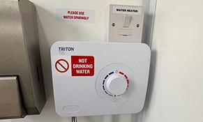
Each instant water heater has its own isolator switch located near the unit. Is the isolator for the unit you are trying to use switched on?
YES – Are all the other electrics in the cabin working? If yes, contact Boss Cabins Service Department. If no, go to section 9.1 to diagnose why the electrics aren’t working.
NO – Turn the water heater isolator on. Is the water hot now?
YES – CONGRATULATIONS!
NO – Are all the other electrics in the cabin working? If yes, contact Boss Cabins. If no, go to section 9.1 to diagnose why the electrics aren’t working..
9.6.3 CHECK IF THERE IS SUFFICIENT WATER IN THE CLEAN WATER TANK?
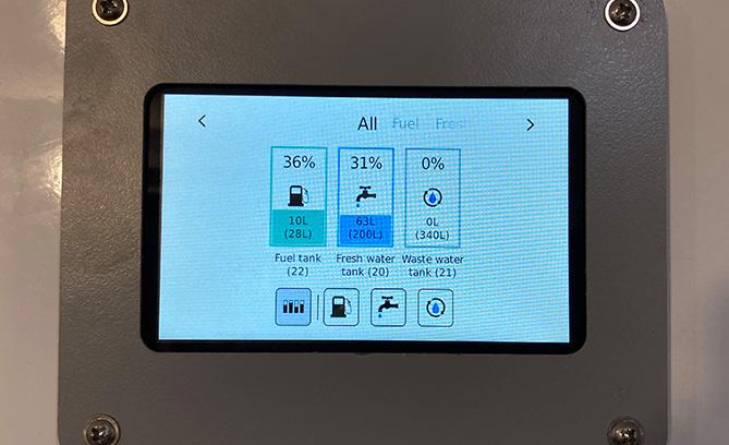
To check the level of the fresh water tank,check the gauge on the wall of the Canteen. Is there sufficient water in the tank?
YES – Your water pump may be broken. Contact Boss Cabins.
NO – Fill the tank with clean water (see Manual Section 6.2 for instructions).
Do the hot water taps work now?
YES – CONGRATULATIONS!
NO – Contact Boss Cabins.
Operation & Maintenance Manual
9 – Diagnostics – Deep Green
To contact Boss Cabins, call 01778 300475 or email info@bosscabins.co.uk 65
9.7 HEATER NOT WORKING
9.7.1 IS THE HEATER SWITCH ON?
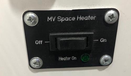
YES – Go to 9.7.2.
NO – Turn Heater switch on.
Is the heater working now?
YES – CONGRATULATIONS!
NO – Go to 9.7.2.
NOTE: To save energy in this Deep Green cabin the heater will turn off automatically after 4 hours. To restart, press the ON button again.
9.7.2 IS THE HIBERNATION ISOLATOR SWITCH ON?
YES – Go to 9.7.3.
NO – Switch on.
Is the heater working now?
YES – CONGRATULATIONS!
NO – Contact Boss Cabins Service Deaprtment.
9.7.3 IS THE HEAT DIRECTED TO THE CORRECT AREA OF THE CABIN?
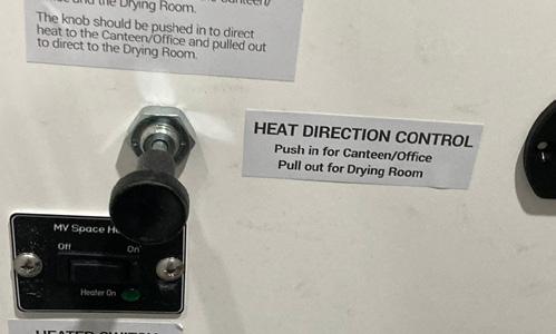
If your cabin has a drying room, the heater in this cabin is designed to direct warm air to one of two areas - either the Canteen and Office or to the Drying Room. When warm air is being blown into the Drying room, none will be blown into the Canteen and Office and vice versa. Do you have the Heat Direction handle in the correct position for where you wish the heat to be blown?
Push IN for Canteen and Office. Pull OUT for Drying compartment.
YES – Contact Boss Cabins Service Department.
NO – Put the handle in the correct position for where you wish the heat to be directed to.
Is the heater working now?
YES – CONGRATULATIONS!
NO – Contact Boss Cabins Service Department.
Operation & Maintenance Manual
9 – Diagnostics – Deep Green
To contact Boss Cabins, call 01778 300475 or email info@bosscabins.co.uk 66
9.8 WATER TANK NOT FILLING WITH RAIN WATER
9.8.1 CHECK RAIN WATER VALVE - IS IT IN THE OPEN POSITION ALLOWING RAIN TO FLOW TO TANK?
NO – Turn to the open position.
YES – Go to 9.8.2.
Is the rain water filling the tank now?
YES – CONGRATULATIONS!
NO – Go to 9.8.2..
9.8.2 CHECK ROOF DRAIN – IS IT BLOCKED BY FALLEN LEAVES AND DEBRIS?

NO – Go to 9.8.2.
YES – Clear away all the leaves and debris.
Is the rain water filling the tank now?
YES – CONGRATULATIONS!
NO – Go to 9.8.2.
9.8.3 CHECK RAIN WATER FILTERS – ARE THEY BLOCKED?
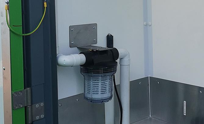
NO – Call Boss Cabins Service Department.
YES – Clean out the filters and remove any debris and particles (see Section 7.1 for instructions).
Is the rain water filling the tank now?
YES – CONGRATULATIONS!
NO – Call Boss Cabins Service Department.
Operation & Maintenance Manual 9 – Diagnostics – Deep Green
To contact Boss Cabins, call 01778 300475 or email info@bosscabins.co.uk
67
9.9 BATTERY NOT BEING CHARGED BY SOLAR PANELS
9.9.1 CHECK WHERE YOUR CABIN IS POSITIONED - IS IT RECEIVING SUNLIGHT?
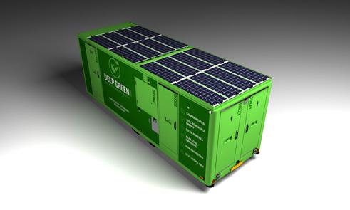
To ensure the optimum perfomance of the solar-powered Deep Green cabin, the unit should be parked in an open exposed area with as little shade as possible over the solar panels. Avoid areas under trees, tunnels or close to tall buildings if at all possible. Is your cabin parked in the sunlight?
YES – Got to 9.9.2.
NO – Move your cabin to a location where it receiveds as much natural daylight as possible.
Is solar energy now being produced in reasonable quantities?
YES – CONGRATULATIONS!
NO – Go to 9.9.2.
9.9.2 ARE THE SOLAR PANELS CLEAN?

To ensure the maximum solar gain, the solar panels should be kept clean and clear of debris. Are the solar panels on this unit clean and clear?
YES – Go to 9.9.3.
NO – Clean the solar panels using a soft brush or cloth. Do not use detergents. Do not lean on the solar panels while cleaning them. See Section 5.5.3 for more information on how to clean your solar panels.
Is sufficient solar energy now being produced during daylight hours?
YES – CONGRATULATIONS!
NO – Go to 9.9.3..
9.9.3 CHECK SOLAR PANEL ISOLATOR SWITCH – IS IT IN ON POSITION?
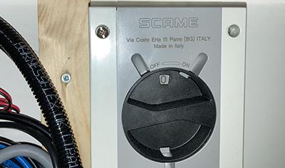
YES – Contact Boss Cabins Service Department.
NO – Turn on the Solar Panel Isolator.
Can you now see acceptable levels of solar energy being produced during daylight hours?
YES – CONGRATULATIONS!
NO – Contact Boss Cabins Service Department.
Operation & Maintenance Manual 9 – Diagnostics – DEEP GREEN
To contact Boss Cabins, call 01778 300475 or email info@bosscabins.co.uk 68
WARRANTIES
10
10.1 MANUFACTURER WARRANTY – 12 MONTHS
All our units are covered by a 12 month manufacturer warranty. The manufacturer Boss Cabins undertakes to replace or repair, free of charge, any defect which the company considers to be due to faulty workmanship or material within 12 months of the sale date, except for:
• Defects arising from neglect, misuse or unauthorised modifications.
• Damage caused by abuse, misuse, dropping or other similar damage caused by or as a result of failure to follow transportation, storage, loading or operating instructions.
• Alterations, additions or repairs carried out by persons other than the manufacturer or their recognised distributors.
• Transportation or shipment costs to and from the manufacturer or their recognised agents, for repair or assessment against a warranty claim, on any mobile welfare unit or component.
• Materials and/or labour costs to renew, repair or replace components due to fair wear and tear.
• Faults arising from the use of non standard or additional parts, or any consequential damage or wear caused by the fitting or use of such parts
IMPORTANT
Warranty may at the sole discretion of the manufacturer be void if the scheduled service/inspections are not carried out in accordance with the service manual. It is essential for any warranty to be given consideration that a warranty claim form is submitted.
The manufacturer and/or their recognised agents, directors, employees or insurers will not be held liable for consequential or other damages, losses or expenses in connection with, or by reason of, the inability to use the mobile welfare unit for any purpose.
If additional equipment or any third party work, modifications or alterations are to be carried out on the welfare unit which will involve any welding, drilling or any form of cutting or distortion of materials, full written approval must be obtained from the manufacturer prior to the work being carried out.
These warranty provisions need to be read in conjunction with the Warranty Conditions detailed within Boss Cabins Ltd’s standard Terms and Conditions of Sale (available on request).
10.2 ANTI-CORROSION WARRANTY – 25 YEARS

In order to make them as long-lasting and sustainable as possible, all Deep Green cabins are constructed from stainless steel unless otherwise requested by the purchaser. If you have purchased a unit made from stainless steel, all stainless steel parts of your cabin chassis are guaranteed to remain corrosion-free for a minimum of 25 years.
No warranty claim will be considered by Boss Cabins Ltd. unless any defective parts are available for inspection by us, or our nominees, to determine the reason or cause of failure, and Boss Cabins Ltd is given the option of repair or replacement.
Operation & Maintenance Manual
10 – Warranties
70
10.3 GENERATOR SERVICING & WARRANTY
All RedBox Power InfinityTM generators carry a warranty of 12 months from date of dispatch or 2000 Hours, whichever comes sooner.
During the warranty period, should the generator fail due to faulty design, materials or workmanship RedBox Power Ltd undertake to rectify the fault in line with our standard warranty terms.
RedBox Power Ltd will accept no responsibility whatsoever for equipment that has failed due to:
• Operation with incorrect fuel, lubricating oil.
• Improper repair or use of parts not supplied by RedBox Power Ltd.
• Lack of, or incorrect, maintenance.
• Fair wear and tear, misuse, negligence, accidental damage, improper storage, incorrect starting / warm-up / run-in or shutdown.
No warranty claim will be considered by RedBox Power Ltd unless any defective parts are available for inspection by us, or our nominees, to determine the reason or cause of failure, and Redbox Power is given the option of repair or replacement.
For servicing requirements please refer to the Redbox Power Generator Operation & Maintenance Manual for full details.
If you have purchased a Deep Green cabin with a Redbox generator, you are automatically entitled to a five year warranty on the generator’s engine and alternator.
Boss Cabins Ltd will accept no responsibility whatsoever for equipment that has failed due to:
• Operation with incorrect fuel, lubricating oil.
• Improper repair or use of parts not supplied by Boss Cabins.
• Lack of, or incorrect, maintenance.
• Fair wear and tear, misuse, negligence, accidental damage, improper storage, incorrect starting / warm-up / run-in or shutdown.
No warranty claim will be considered by Boss Cabins Ltd unless any defective parts are available for inspection by us, or our nominees, to determine the reason or cause of failure, and Redbox Power is given.
10 – Warranties Operation & Maintenance Manual
10.4 EXTENDED GENERATOR ENGINE & ALTERNATOR WARRANTY – 5 YEARS 10.5 SOLARTRACK TM PARTS WARRANTY · Standard 5-year warranty on all Solar Track electronics (Extended to 10 years for a small fee).
Standard 5-year warranty on all engine and alternators.
Standard 3-year warranty on all SOLARTrackTM Lithium batteries. **Warranty applied to new generation Deep Green cabins and covers Surbo, shunt, BMV, Easy Solar, Solar Charger, battery protect system & display screen** 71
·
·
TOWING ADVICE & LEGAL OBLIGATIONS
11
11.1 LEGAL OBLIGATIONS – CABIN & TOWING VEHICLE
11.1.1 TOWING SPEED RESTRICTION
The towing speed limit for this unit is not to exceed 50 mph (80 km/h). The unit is not designed for towing or manoeuvring at higher speeds.
11.1.2 TOWING VEHICLE
The towing vehicle must be suitable for towing the unit. The selection must be made whilst considering the maximum mass (MTPLM) and the towing limit, the Gross Train Weight (GTW) and the load imposed on the rear axle of the towing vehicle.
11.1.3 VIN PLATE
All modern trailer vehicles must carry a manufacturer’s plate giving certain details. From October 2012 this has become part of the European type approval process. The plates must contain information relevant to the loading and towing of the trailer.
The plate is affixed to the front bulkhead of the trailer under the anti-vandal cover.
It contains the Vehicle Identification Number (VIN) which is also marked on the right side of the drawbar.
It also contains the European Type approval reference [ 3 ] and details about the mass of the unit.
The maximum mass (MTPLM) of the trailer is shown at position 5 whilst the maximum imposed loading on the coupling is shown at position 6 and the maximum axle load at position 7.
The operator of the trailer should use these weights to determine that the tow vehicle is suitable and that the unit is being used legally.
Operation & Maintenance Manual BOSS CABINS LTD E11*2007/46*0392 2300kg 0-150kg 1-2300kg SJWCS142UH0S4C001
2 1 3 4 5 6 Number Refers To 1. VIN Plate 2. Vehicle Type Approval 3. Serial Number 4. Max Weight 5. Coupling Rated Mass 6. Axle Rated Mass 11 – Towing Advice & Legal Obligations 73
11.1.4 TOWING BRACKET
The towing vehicle must be fitted with a good quality towing bracket, preferably in accordance with Directive 94/20/EC and fitted and used in accordance with the manufacturer’s instructions.
11.1.5 REGISTRATION PLATE
The cabin must be fitted with a correctly positioned approved 520 × 120 mm number plate in the place provided. The plate must bear the same registration mark as that of the towing vehicle.
11.1.6 TOWING MIRRORS
Before using a trailer on the road the operator must ensure that the visibility through the rear view mirrors is correct.
The Welfare Hire Nationwide welfare unit may be wider than the towing vehicle. This means the standard mirrors fitted to the towing vehicle will be inadequate for compliance with the relevant legal requirements.
Extension mirrors must be fitted and adjusted to ensure the yellow shaded area in the diagram is visible in the mirrors for both sides of the vehicle.
Mirrors fitted must be “e” marked and correctly fitted to give adequate visibility.
Operation & Maintenance Manual
5m 1m 1m 4m 30m Class II Mirrors Compulsory for M2, M3, N2 & N3 vehicles. 4m 4m 20m Class III Mirrors Compulsory for M1 vehicles. 11 – Towing Advice & Legal Obligations 74
11.1.7 ROAD LIGHTING
It is an offence to tow a trailer or permit a trailer to be towed on the road without adequate and properly functioning lighting.
The trailer is delivered with fully compliant road lighting.
The trailer is connected to the towing vehicle using a standard 13 pin plug and socket.
It is the responsibility of the operator to ensure that all lights are operating and undamaged before using the unit on the public roads.
This class of trailer requires the following lights to be fitted and working.
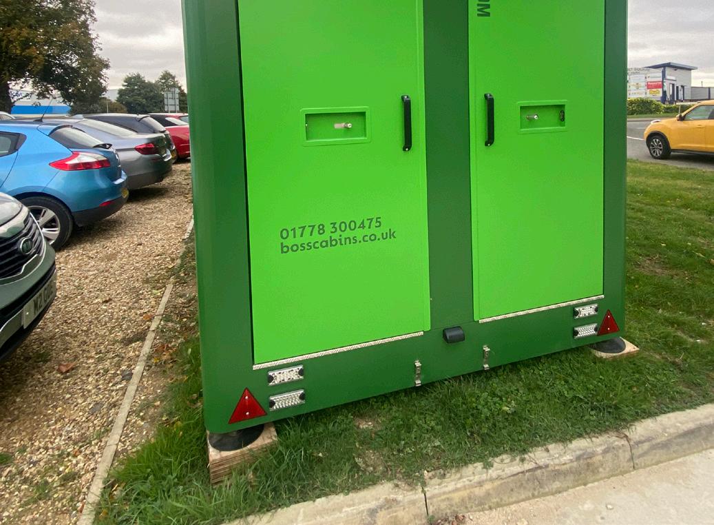
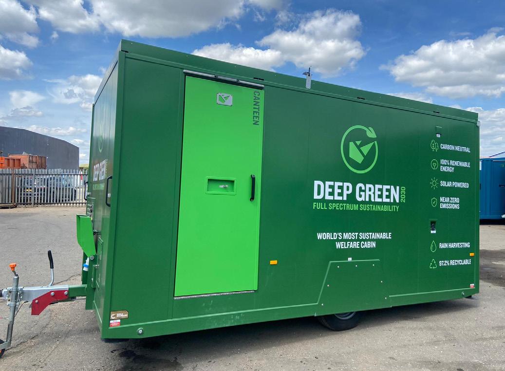
Operation & Maintenance Manual
Number Type Colour Quantity 1. Number Plate Lamp White 1 or 2 2. Mini LED Combination Lamp consisting of: 2a. Stop Lamp Red 2 2b. Rear Position Lamp Red 2 2c. Direction Indication Amber 2 3. Mini LED Combination Lamp consisting of: 3a. Fog Lamp Red 1 3b. Reversing Lamp White 1 4. Triangular Reflector Red 2 5. End Outline Marker Lamp Red and White 2 6. Side Marker Lamp Amber 4 7. Front Position (Side) Lamp White 2 1 4 5 6 7 3 2 11 – Towing Advice & Legal Obligations 75
11.2 LEGAL OBLIGATIONS – TOWING VEHICLE DRIVER
People are often ignorant of the towing laws and legal requirements especially when only towing with a standard car licence (Category B).
For photo card licences issued in the UK and other EU countries, the vehicle categories you are entitled to drive are shown on Line 9 on the front. A more detailed breakdown and the applicable dates are shown on the rear.

If you have a B1 or higher category driving licence, you are legally permitted to tow any size of Welfare Hire Nationwide trailer.
If you have a Category B and BE licence only (awarded on passing the standard UK driving test), check the date your licence was issued and use the following information and flow diagrams to determine what trailers you are able to tow and to match the tow vehicle to the trailer.
MTPLM
MRO
MAM
GTW
MTM
Maximum Technically Permissible Laden Mass (of the trailer).
Mass in Running Order (unladen or ex-works mass).
Maximum Authorised Mass (Max weight of Towing vehicle).
Gross Train W eight (Trailer & Towing vehicle weights combined).
Maximum Towable Mass (the weight a towing vehicle is allowed to tow as indicated by its manufacturer).
Operation & Maintenance Manual
11 – Towing Advice & Legal Obligations 76
CAT
CAT B
LICENCE
HELD BEFORE 1 ST JAN 1997
Does the tow vehicle have more than 8 passenger seats (not including the driver)?
Is the trailer MTPLM greater than 750kg?
Does trailer MTPLM exceed the MRO of the tow vehicle?
Does trailer MTPLM exceed the MRO of the tow vehicle?
Does the trailer have overrun brakes?
Is the trailer MTPLM greater than 50% of the MRO of the tow vehicle?
Does trailer MTPLM exceed the towable mass of the tow vehicle?
Does trailer MTPLM plus the tow vehicle MAM exceed the allowable combination GTW?
Does the GTW exceed 8250kg?
Can’t tow trailer without further license qualification OK TO TOW
Operation & Maintenance Manual
No
B LICENCE HELD BEFORE 1ST JAN 1997
No No No No No No No No Yes Yes Yes Yes Yes Yes Yes Yes Yes Yes 11 – Towing Advice & Legal Obligations 77
CAT B LICENCE HELD AFTER 1ST JANUARY 1997 BUT BEFORE 19TH JANUARY 2013
CAT B LICENCE HELD AFTER 1 ST JAN 1997 BUT BEFORE 19 TH JAN 2013
Does the tow vehicle have more than 8 passenger seats (not including the driver)?
Does the tow vehicle MAM exceed 3500kg?
Does trailer MTPLM exceed the MRO of the tow vehicle?
Does trailer MTPLM exceed 750kg?
Does trailer MTPLM exceed the MRO of the tow vehicle?
Does trailer MTPLM exceed the towable mass of the tow vehicle?
Does the trailer have overrun brakes?
Is the trailer MTPLM greater than 50% of the MRO of the tow vehicle?
Does trailer MTPLM exceed the towable mass of the tow vehicle?
Does trailer MTPLM plus the tow vehicle MAM exceed the allowable GTW?
Does the GTW exceed 4250kg?
Does trailer MTPLM plus the tow vehicle MAM exceed the allowable GTW?
Does the GTW exceed 3500kg?
Operation & Maintenance Manual
Can’t tow trailer without further license qualification
No No No No No No No No No No No No Yes Yes Yes Yes Yes Yes Yes Yes Yes Yes Yes Yes Yes Yes
OK TO TOW 11 – Towing Advice & Legal Obligations
78
CAT
CAT
Does the tow vehicle have more than 8 passenger seats (not including the driver)?
Does the tow vehicle MAM exceed 3500kg?
Does trailer MTPLM exceed the MRO of the tow vehicle?
Does trailer MTPLM exceed 750kg?
Can’t
Does trailer MTPLM exceed the MRO of the tow vehicle?
Does the trailer have overrun brakes?
Is the trailer MTPLM greater than 50% of the MRO of the tow vehicle?
Does trailer MTPLM exceed the towable mass of the tow vehicle?
Does trailer MTPLM plus the tow vehicle MAM exceed the allowable GTW?
Operation & Maintenance Manual
B LICENCE HELD AFTER 19TH JANUARY 2013
OK TO TOW
B LICENCE HELD AFTER 19 TH JAN 2013
qualification No Yes Yes
tow trailer without further license
No Yes
Yes
No
Yes
No No Yes Yes Yes Yes No
Yes Yes No No
11 – Towing Advice & Legal Obligations No 79
Does the GTW exceed 3500kg?
11.3
DRIVING ADVICE
Dependant on the model, Deep Green welfare units are equipped with either a single or tandem axle. For inexperienced users this may make manoeuvring difficult, especially where space is limited. Don’t take chances, if in doubt and where visibility is limited always get someone to guide or assist you.
The addition of a trailer lengthens the effective wheelbase of the towing vehicle, it may also impair the rearward visibility and make cornering and reversing more challenging.
Boss Cabins strongly recommend that anyone towing one of their welfare units undertakes professional training and accreditation.
11.3.1 TURNING LEFT
When turning left (in the UK) it is important to remember that the trailer does not take the same route around the corner as the towing vehicle. For example if the towing vehicle is positioned too close to the kerb or the driver does not allow sufficient additional distance when turning, the trailer will cut across the corner. This will inevitably damage the trailer and possibly the towing vehicle.
More seriously it could cause injury to a pedestrian or cyclist, and cause damage to the highway infrastructure.
Allow plenty of time to manoeuvre and adjust your road position so as to be further from the kerb, without conflicting with other traffic.
Never overtake slower moving traffic before making a turn. Check your mirrors, especially the left side before making a left turn and ensure there are no cyclists or pedestrians that may be affected by the manoeuvre. Check the trailer position, and look into the junction to check for any conflicting traffic. Make your turn slightly later than if you were driving without a trailer, this widens the turning circle, allowing the trailer to clear the kerb.
Operation & Maintenance Manual
11 – Towing Advice & Legal Obligations 80
11.3.2 REVERSING THE UNIT
Reversing a trailer requires additional skills, and observation.
1) Position the towing vehicle parallel to the kerb and if conditions allow, approximately 1m to 1.5m from it.
Allow at least one trailer length from the rear of the trailer to the junction if possible.
Check behind the trailer for any obstructions, then when the road is clear start the manoeuvre by reversing slowly straight back.
2) Whilst reversing slowly turn the steering wheel opposite to the direction of the turn. Check your mirrors both sides for conflicting traffic and to watch the position of the trailer. As the rear of the towing vehicle turns away from the kerb, watch the rear of the trailer and it will start to turn into the junction.
4) When fully into the junction, turn the steering to the left to straighten up the trailer. You may need to steer further to the left than is normal to compensate for the trailer, so ensure you use your mirrors to look for conflicting traffic and obstructions.
3) As the trailer starts to turn, turn the steering wheel into the normal lock for the curve. Follow the trailer into the junction.
If the trailer starts to turn in too tightly, turn the steering wheel further to the left to correct it.
CAUTION
If you lose control of the trailer whilst reversing, the most likely result will be to jack-knife. This is where the trailer turning circle decreases quickly and the towing vehicle cannot steer to correct it. In this condition the only method of correction is to stop, then pull forward to straighten up the trailer, then start the reversing procedure again.
Jack-knifing the trailer can cause instability, and inevitably causes damage to trailer and the towing vehicle.
Operation & Maintenance Manual
11 – Towing Advice & Legal Obligations 81
OTHER INFORMATION
12
12.1 SAFETY DECALS
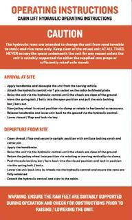
General operating instructions for arriving on site, towing and departing.

Warns the operator that 230V equipment is fitted and in use in the cabin.No unqualified or unauthorised personnel are allowed to work on or maintain this equipment
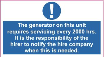
Generator service interval decal.
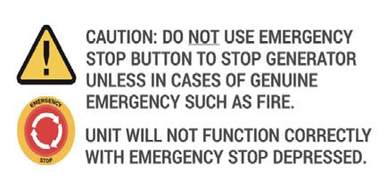
Emergency Stop button warning - only use in case of genuine emergency.

Warns of proximity of hot surfaces or exhaust outlets.

Warns user to ensure the hydraulic cylinders are properly supported before being lowered.

Warns of legal obligation not to smoke or vape in the cabin.

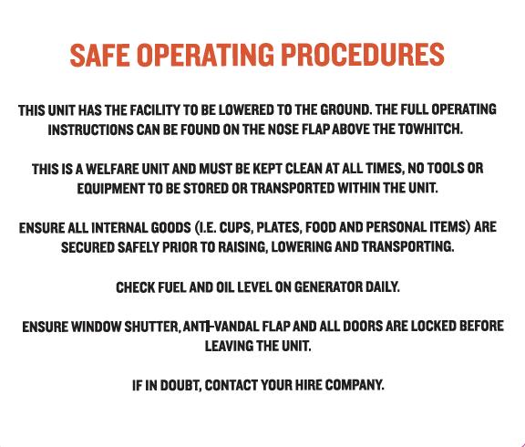
General safety instructions. Roles and responsibilities for hirers and operators.

Affixed to washing facilities to advise the operator that water in these units may not be fit for drinking.
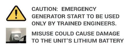
Indicates location of Emergency Generator Restart Button.

Indicates that there is a vent that must not be obstructed.

Warns user to make sure axle rod is locked in place before towing cabin
Advises user how to reset the generator after an alarm.

Instructions on how to use an external electrical supply.

Advises correct tyre pressure.
Operation & Maintenance Manual
12 – Other Information
83
LEGAL REQUIREMENTS –MOBILE WELFARE
All Boss Cabins Deep Green mobile welfare units are fully compliant with all current legislation and directives regarding welfare facilities.
13
13.1 ONSITE WELFARE PROVISION –CONSTRUCTION (DESIGN AND MANAGEMENT) REGULATIONS 2015
The welfare of all personnel employed on construction sites and in similar environments is the responsibility of employers, contractors and clients and is set out in the Construction (Design and Management) Regulations 2015 (UK only, other EU countries and non-EU countries regulations may vary).
The use of welfare units will allow employers to comply with some or all of the stipulations below. The nature and scale of facilities required will depend on the size, location and type of project. For everyone, on site facilities must include:
TOILETS
Toilets should be suitable and sufficient, ventilated, lit and kept in a clean and orderly condition. Washing facilities must be provided so that workers can use them immediately after using the toilet or urinal, even if they are provided elsewhere. Our toilets all comply with current mobile toilet regulations BS EN 16194 2012 – Mobile non-sewer-connected toilet cabins.
WASHING FACILITIES
General washing facilities must be suitable and sufficient, kept clean and orderly and with basins or sinks large enough for people to wash their face, hands and forearms.
The facilities should include:
• Clean hot and cold, or warm, running water.
• Soap or other suitable means of cleaning.
• Towels or other suitable means of drying.
DRINKING WATER
Drinking water must be provided or made available at readily accessible and suitable places. Cups are required unless the supply is in a jet from which people can drink easily.
CHANGING ROOMS AND LOCKERS
Changing rooms are needed where workers have to wear special clothing for the purposes of their work and cannot be expected to change elsewhere. The rooms must be provided with seating, means of drying and keeping clothing and personal effects secure.
FACILITIES FOR REST AND CONSUMING REFRESHMENTS
Rest rooms or rest areas are required equipped with tables and seating (with backs) sufficient for the number of persons likely to use them at any one time. There should be arrangements for meals to be prepared and eaten, plus means for boiling water. In cold weather, heating should be provided.
Operation & Maintenance Manual
13 – Legal Requirements – Mobile Welfare 85
13.2
ROADWORTHINESS –VCA TYPE APPROVAL UNDER DIRECTIVE 2007/46/EC

These Boss Cabins Deep Green mobile welfare units have been granted VCA Type Approval under Directive 2007/46/EC and are certified roadworthy.
13.3 ELECTRIC INSTALLATIONS – BS7671 IET WIRING REGULATIONS 18TH EDITION

The electrical installations in Boss Cabins Deep Green cabins are independently checked and conform with the latest legal recommendations BS7671 IET Wiring Regulations 18th Edition.
In addition, we certify all our cabins with Gold Standard Electrics, our own independenttesting scheme with standards that meet and exceed current regulations.
Operation & Maintenance Manual
13 – Legal Requirements – Mobile Welfare 86

DEEP GREEN FULL SP E C TR UM SU S TAINABILI T Y 203 0 ENGINEERED BY BOSS CABINS Boss Cabins, BCS House, Pinfold Road, Bourne PE10 9HT, United Kingdom info@bosscabins.co.uk 01778 300475 www.bosscabins.co.uk