
The following section identifies items on the welfare unit that will from time to time require maintenance. Some of these can be carried out by the user, whilst others may need to be undertaken by suitably qualified and experienced technicians.
MAINTENANCE 8
• Never work beneath any unsupported load or structure.
• Always move the vehicle to a safe place away from traffic or site equipment before attempting maintenance.
• Never climb on or work over or above any device without suitable fall restraint equipment.
• Ensure the unit is parked on firm level ground before changing wheels.
• Always take care when working with or connecting any electrical equipment. Damaged or inadequately insulated equipment can lead to electrocution causing fire, burns , serious injury or death.
• Always follow instructions.
• If in doubt ask for assistance from suitably qualified personnel.
• Always abide by the work site’s published Safety Policy.
8.1 CHANGING A WHEEL
If you suffer a puncture whilst towing, follow these instructions to enable you to change or repair a wheel.

Operation & Maintenance Manual
8 – Maintenance 87
WARNING WATCH THE VIDEO
8.1.1 PREPARATION
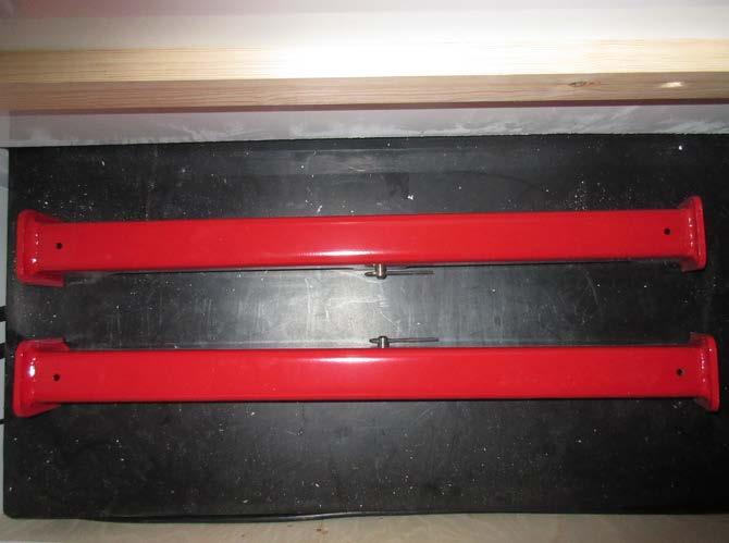
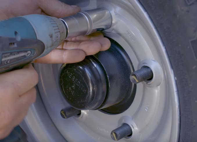
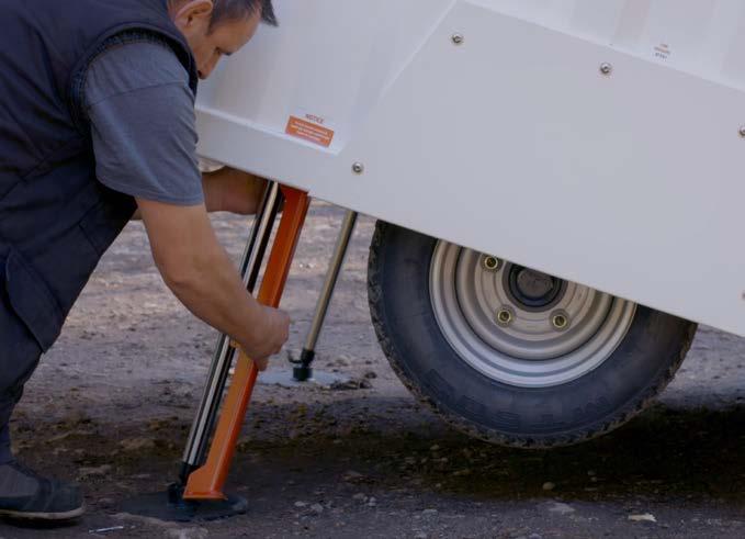
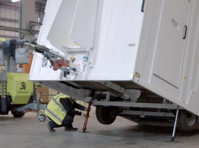
1. Make sure the unit is disconnected from the towing vehicle. Remove the hydraulic cylinder props from their stowage compartment. Depending on your ram configuration, there will be either 2 or 4 cylinder props inside a bench unit in the cabin.
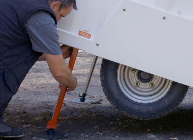
2. Raise the cabin using the lift cylinders (rams) until the wheels are clear of the ground. For instruction how to do this, go to Manual Section 3.4 and follow the first steps. Once the wheels are raised, place the cylinder props on each leg of the cabin.

3. Secure the cylinder props using the pin and clip.
IMPORTANT
You must use one prop on every cylinder (ram) of your cabin.
8.1.2A FOR NEWER MODELS WITH DETACHABLE WHEEL ARCH
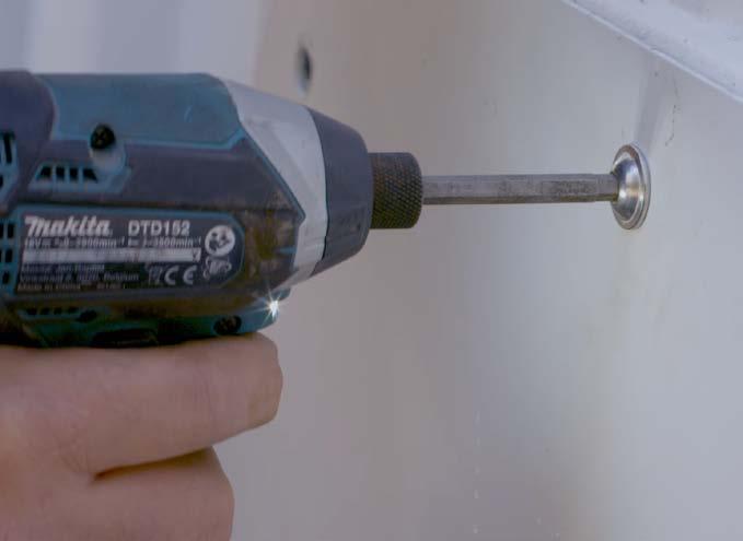
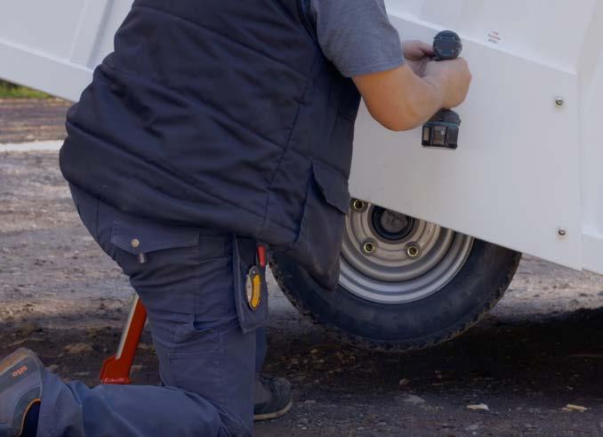
1. With the unit suitably supported, remove the screws that secure the wheel guard panel and withdraw it from the side of the cabin.
2. Loosen the wheel nuts and remove the wheel.
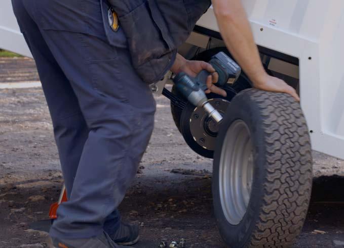
3. Repair the wheel or replace with a suitable spare.
Operation & Maintenance Manual
8 – Maintenance
88
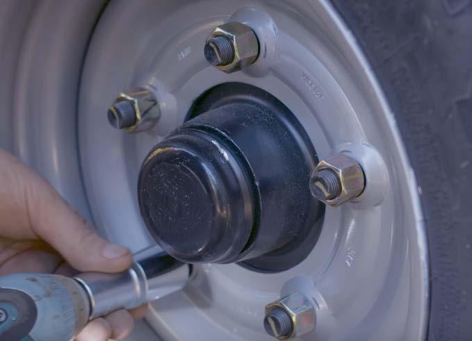
4. Refit the wheel nuts and tighten to 160Nm.
5. To refit the wheel arch, reverse the removal procedure and replace all screws.
6. Remove the cylinder props. Use the hydraulic system to lower the cabin back onto its wheels and then replace the props and hydraulic remote control back in their stowed positions inside the cabin.
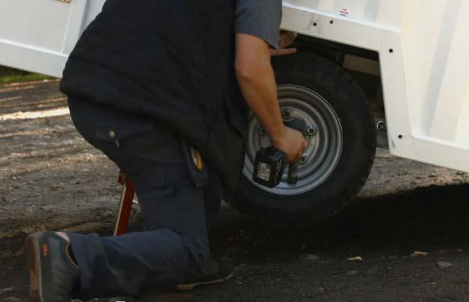
8.1.2B FOR EARLIER MODELS WITHOUT DETACHABLE WHEEL ARCH
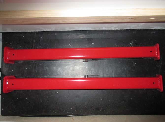
1. Remove the red cylinder props from their storage position within the cabin.
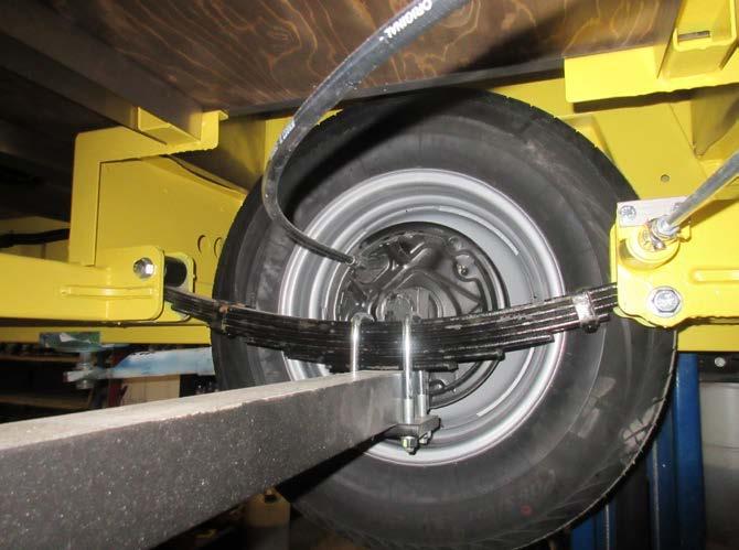
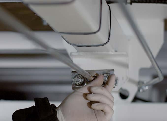
2. With the cabin still lowered and wheels on the ground, remove the lower retaining bolts [1] from the leaf spring [2] mounting plate on both sides of the cabin so the entire axle [3] is released. The bolt is the one in front of the wheel under the locking pin.
3. Then raise the cabin using the electric hydraulic system to its highest point and secure the cabin in the raised position using the cylinder props (see Manual Section 8.1.2A for instructions).
4. As you have released the axle, the wheels and axle will remain on the ground. Use a jack to lift the axle [3] so that the wheels lift slightly off the floor.
5. Loosen the wheel nuts and remove and replace the wheel, tightening the wheel nuts to 160Nm.
6. Remove the jack from under the axle so the wheels are on the floor.
7. Remove the cylinder props from the rams and lower the cabin back down onto the wheels.
8. Refit the lower retaining bolts to the leaf spring mounting plate and torque to 25 Nm.
9. Replace the red cylinder props in their stowed position inside the cabin.
Operation & Maintenance Manual
8 – Maintenance 1 2 3 89
8.2 BRAKE SETTING PROCEDURE – PREPARATION SINGLE AND TWIN AXLE
WATCH THE VIDEO
CAUTION
Make sure the unit is on level ground to carry out this procedure.
1. Remove the hydraulic cylinder props from their stowage compartment. Depending on your ram configuration, there will be either 2 or 4 cylinder props inside a bench unit in the cabin.
2. Raise the unit using the lift cylinders (rams). For instruction how to do this, go to Manual Section 3.4 and follow the first steps. Once the wheels are raised, place the cylinder props on each leg of the cabin.
3. Secure the cylinder props in place using the pin and clip.
IMPORTANT
You must use one prop on every cylinder (ram) of your cabin.
CAUTION
During brake setting, only rotate the wheels in a forward direction. Also do not use the brake rod as a means of adjusting the brakes.
Operation & Maintenance Manual
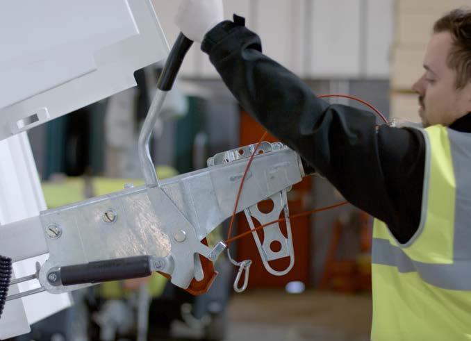
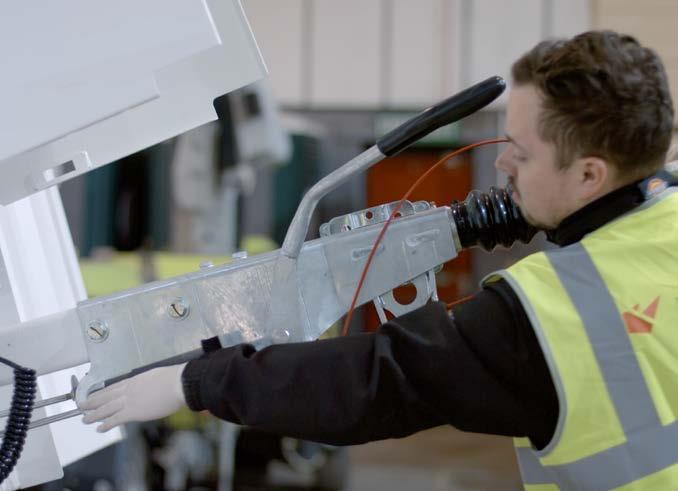
4. Release the parking brake and ensure the draw tube is fully extended out of the over run coupling.
8 – Maintenance
90
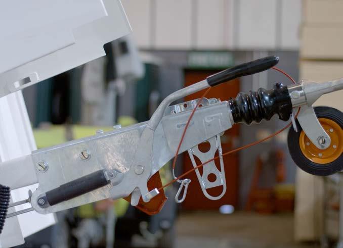
8.2A BRAKE SETTING PROCEDURE SINGLE AXLE
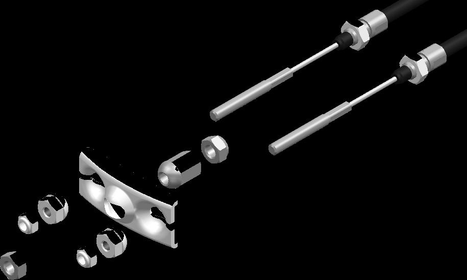
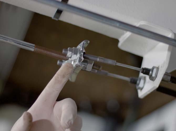
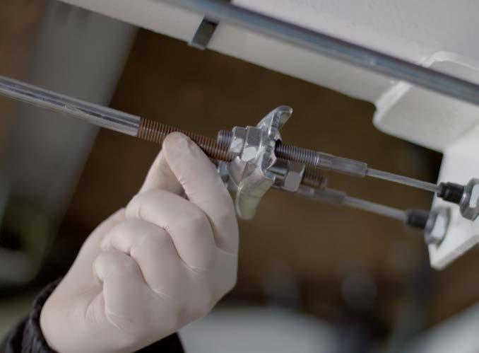
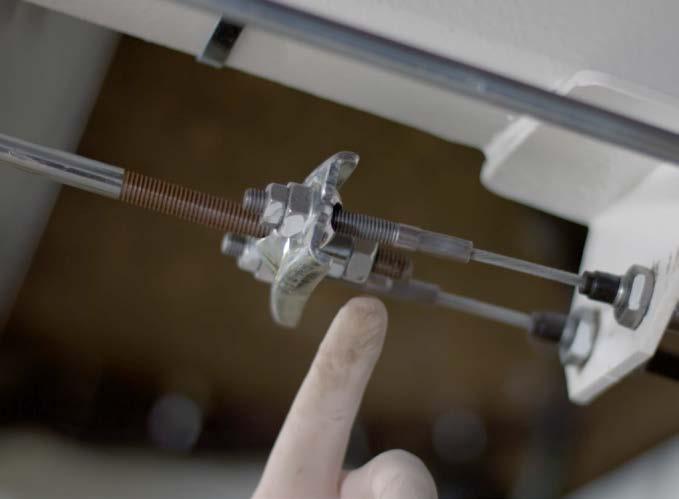
1. Brake cable outer locknut
2. Brake cable spherical nut
3. Brake cable compensator bar
4. Brake rod spherical nut
5. Brake rod outer locknut
6. Brake cable
Operation & Maintenance Manual
1. Check that the brake cables are not under tension, if necessary reduce this tension by adjusting the spherical nuts at the ends of the cables on the cable compensator bar.
8 – Maintenance 5 4 3 2 1 6 91
2. Check that the brake rod is not under tension, if necessary reduce the tension by adjusting the spherical nut at the end of the rod on the cable compensator bar.
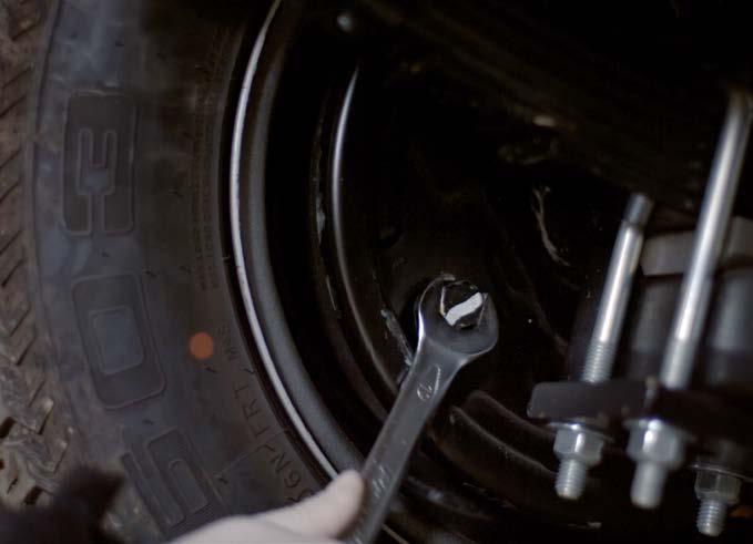
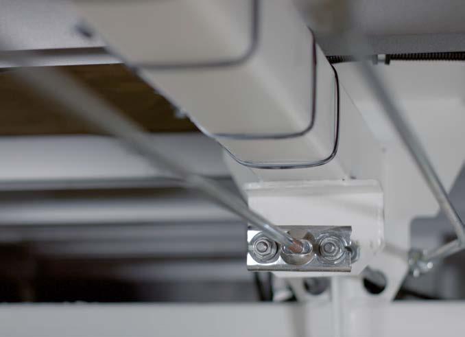
3. To set the Wheel Brakes, tighten the adjusting screw on the rear of the brake unit back plate (clockwise) until it is not possible to turn the wheel by hand. Turn the adjusting screw back (counter clockwise) by approx 1/2 a turn (180 deg) or until the wheel turns freely by hand. Make sure you are turning the wheel in a forwards direction. Repeat this for each wheel.
Some slight “grinding noises” which do not impede the movement may be heard, this is normal.
6. Finally set the Parking Brake Lever. Firmly activate the handbrake repeatedly in order to re-seat the braking components. When applying the handbrake lever do not force it further back than its normal rest position.
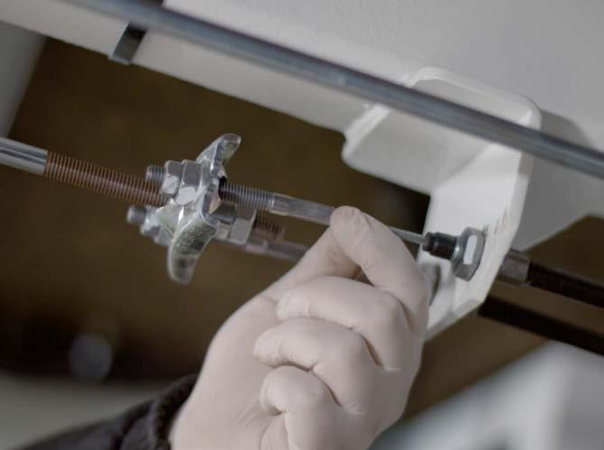
4. Next set the Cable Compensator Bar. This bar must be aligned perpendicular (90º) to the direction of travel. Once in position secure the position using the spherical nuts, then tighten the outer lock nuts onto the spherical nuts.
5. Next set the Brake Rod. Adjust the brake rod by tightening or loosening the adjusting spherical nut until there is neither tension or free play in it. Once the spherical nut is holding the brake rod correctly, then tighten the outer lock nut onto the spherical nut to secure.
If the wheels have inadvertently been rotated backwards, the auto reverse mechanism may have been activated. If this is the case or the brakes do not operate correctly, check for faults and repeat the whole procedure.
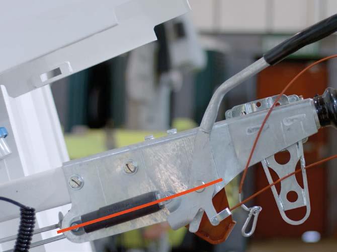
7. Check the orientation of the Cable Compensator Bar beneath the cabin again, making sure that it remains in position, perpendicular to the direction of travel. Then move handbrake lever to the desired position so that all three pivots are in line as shown in this image.
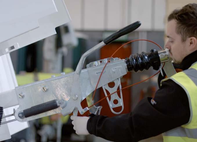
8. Check that the brake reaction lever is in contact with the handbrake lever and has 10–15mm of movement away from the handbrake lever when it is pushed manually.
Operation & Maintenance Manual
NOTE
8 – Maintenance 92
WARNING
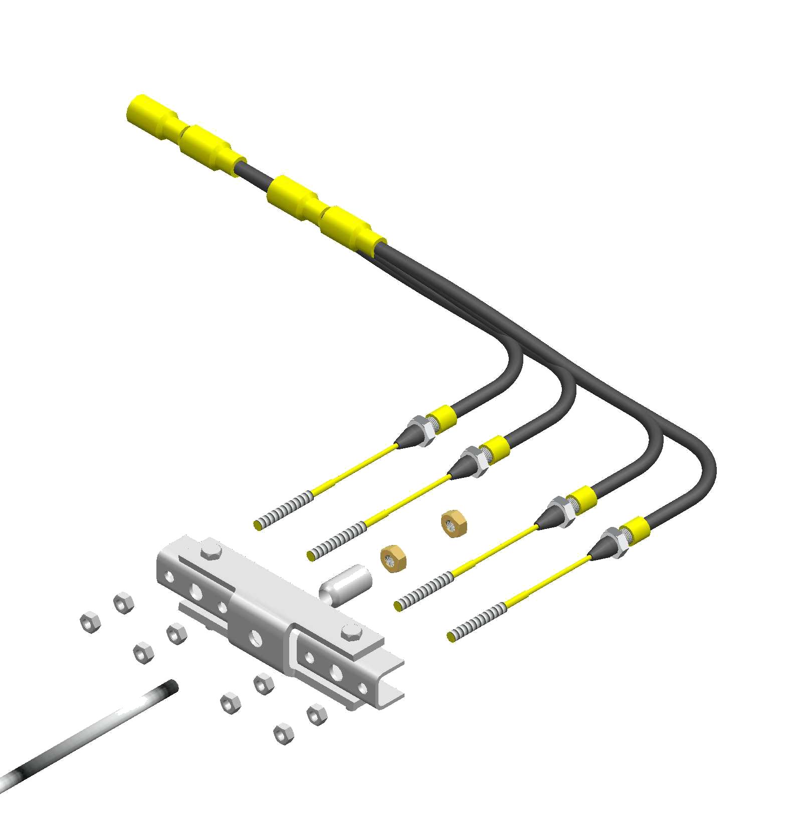
this tension by adjusting the spherical nuts [2] at the ends of the cables on the cable compensator bar [3].
2. Check that the brake rod [4] is not under tension, if necessary reduce the tension by adjusting the spherical nut [5] at the end of the rod behind the cable compensator bar [3]
3. To set the Wheel Brakes, tighten the adjusting screw on the rear of the brake unit back plate (clockwise) until it is not possible to turn the wheel by hand. Turn the adjusting screw back (counter clockwise) by approx 1/2 a turn (180 deg) or until the wheel turns freely by hand. Make sure you are turning the wheel in a forwards direction. Repeat this for each wheel. See image in Section 8.2A for clarification.
must be aligned perpendicular (90 degrees) to the direction of travel. Once in position tighten the 4 lock nuts [6] onto the 4 spherical nuts [2] attached to the brake cables.
5. Next set the Brake Rod. Adjust the brake rod by tightening or loosening the adjusting spherical nut until there is neither tension or free play in it. Once the spherical nut [5] is holding the brake rod [4] correctly, then tighten the outer lock nut [7] onto the spherical nut to secure.
6. Finally set the Parking Brake Lever. Firmly activate the handbrake repeatedly in order to re-seat the braking components. When applying the handbrake lever do not force it further back than its normal rest position.
If the wheels have inadvertently been rotated backwards, the auto reverse mechanism may have been activated. If this is the case or the brakes do not operate correctly, check for faults and repeat the whole procedure.
NOTE
Some slight “grinding noises” which do not impede the movement may be heard, this is normal.
8 – Maintenance 1 5 2 6 7 3 4 93
7. Check that the orientation of the Cable Compensator Bar – all three pivots should be in line as shown.
8. Check that the brake reaction lever is in contact with the handbrake lever and has 10–15mm of movement away from the handbrake lever when it is pushed manually.
8.3 BRAKE CHECK AND TEST
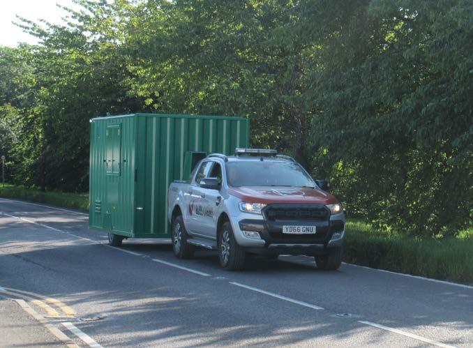
Ensure that any testing carried out on public or private roads is done taking due account of other road users.
ROAD TEST A
1. Drive in a straight line at 20/25 mph; apply the brakes gradually and firmly to produce a smooth stop.
2. Observe the behaviour of the cabin during braking (this may be more easily done by a passenger in the towing vehicle rather than the driver).
3. If the cabin is pulling to one side under braking or the wheels are locking up on one side, the system MUST be checked and reset before proceeding. Once smooth straight line braking is achieved at this speed, proceed to Road Test B.
ROAD TEST B
1. Drive in a straight line at 35/40mph (assuming speed limits allow) and apply the brakes firmly and steadily without locking up the trailer wheels.
2. Once again observe the behaviour and handling of the cabin under braking and, as in Road Test A, readjust the system if braking is not even on both sides.
All braking should be gradual and sympathetic to the system. Aggressive and violent braking should be avoided during these procedures in order to safely judge the braking performance and obtain optimum bedding in of the brake linings.
ROAD TEST C
1. Finally drive at 50mph (if speed limits allow) and apply the brakes to reduce speed to 30mph, accelerating back to 50mph.
2. If satisfied that the cabin is braking evenly and steadily, repeat the manoeuvre 3 or 4 times.
Operation & Maintenance Manual
8 – Maintenance 94
NOTE CAUTION
BEDDING IN THE BRAKES
The brake linings will wear in, improving in performance as they take on the contours of the drum. They will also generate heat which in turn will optimise the coefficient of friction on the linings and provide improved braking performance as they “bed in”. Dependent on the type of driving style used, the brakes may not achieve optimum efficiency either in overrun or on the brake lever for 500 miles. Stop/start driving will bed the brakes in more quickly than motorway driving where the brakes are hardly used.
In the event of the shoes adhering to the drum it will be necessary to release them using the following procedure:
1) Turn the adjuster bolt anticlockwise by approximately half a turn.
2) Tap the bottom of the back plate using a soft faced or wooden mallet.
3) If the brake shoes have not released, jack up the trailer as described earlier in this manual.
4) Remove wheel assembly.
5) Tap brake drum with mallet.
6) Once the brake shoes have released, readjust the brake. Please note that there may be corrosion within the drum that has been a contributory factor to the brake linings sticking. It is recommended as good practice to therefore remove the drums and clean them before the cabin is once again parked. Frequent use of the overrun brakes should ensure that the drum surface remains free of corrosion.
Brakes should be readjusted as often as is necessary. There is no set time or distance limit. Users should check the slack in the system before each journey and readjust accordingly. Most couplings have 90 or 100mm of travel through the drawtube (connecting rod) and damper. The simplest way to check the slack on most systems is to push the bottom of the brake reaction lever forward and if the movement is more than half of the coupling travel, i.e. 45 or 50mm, it is recommended that the brakes are readjusted.
A service should also be performed on the braking system at regular intervals. The timing of this may depend on the use of the cabin, in terms of distance and driving style.
Cabins that are for occasional use only should also be checked to ensure that no parts have seized. During these service checks the drums should be removed and the brakes checked for damage and wear. Linings should be replaced if there is less than 2mm lining thickness left on the shoe. This should ensure that the linings do not wear out before the next service.
IMPORTANT
During the bedding in process the properties at the surface of the lining change. Until the brakes are bedded in according to this recommended procedure there is a possibility that the brake shoes may adhere to the brake drum surface when parked with the handbrake lever in the “on” position.
Since the introduction of asbestos-free brake linings this has been found to occur with ALL makes of lining material. It is therefore recommended that, if the cabin is to be parked for extended periods or in damp or humid conditions, the wheels are chocked and handbrake lever released.
In addition, it is also good practice, if reversing the cabin into position, to draw the cabin forward slightly before leaving. This ensures that the brake shoes have returned to their normal running position.
Operation & Maintenance Manual
8 – Maintenance 95
NOTE: An annual safety checking service is available from Boss Cabins Ltd. Contact the manufacturer or their agent for more information.
Operation & Maintenance Manual
Daily Weekly Monthly 6 months Annual Before transporting Before use on arrival to site Manual section Check and fill drinking water container (canteen) or empty if transporting X X X 6.1 Check and fill clean water tank (canteen) or empty if transporting X X X 6.2 Check and remove waste water (canteen) X X 6.3 Replenish water cups X X 6.6 Check and fill dispensers – hand towels, soap and sanitiser X X 6 Check and refill generator fuel level X X 4.3 Check generator engine oil level (Redbox) X X 4.3 Check generator engine oil level (Redbox Infinity) X X 4.3 Check and fill fresh water tank (chemical toilet) or empty if transporting X X X 7A.8 Check fresh water / waste water levels (fresh water toilet) X X X 7B.8 Check CO monitor function X X 6.8 Check CO monitor sensor X X 6.8 Check electrical system function (RCD board) X X 8.5 Check security of door and window locks X X X 6.11 Check operation of anti vandal cover X X 3.5 Check for wear in drawbar coupling X Remove internal door panels and grease moving parts of door locking mechanisms X Check for corrosion and mechanical defects in braking system X Check tyre inflation X X 8.1 Grease the axle locking pins and towing coupler X X Check brake setting/operation X X 8.2 Check brake function X X 8.3 Check tyre condition X X Check coupler function X X 3.2 Check function of all lights X X Check breakaway cable function X X Grease bright metal and other exposed parts X X ILMS Test Box Procedure (Eco Ultimate Only) X 8.5
8.4 SERVICE CHECKS
8 – Maintenance Service Intervals Redbox 1000 hours (Hatz engine), 250 hours (Yanmar engine) Redbox Infinity 2000 hours 96
8.5 ELECTRICAL CHECKS
In order to ensure correct function of the electrical system of your cabin and the safety of all operatives, there are certain electrical checks that should be carried out.
Some of these can be undertaken by the users, whilst others may need to be undertaken by qualified and suitably experienced technicians.
WARNING
• Always take care when working with or connecting any electrical equipment. Damaged or inadequately insulated equipment can lead to electrocution causing fire, burns, serious injury or death.
• Always follow instructions. If in doubt, ask for assistance from suitably qualified personnel.
• Always abide by the work site’s published Safety Policy.
8.5.1A FUSE BOX CHECK STANDARD, ECO+, ECO HYBRID
According to BS7671 IET Wiring Regulations 18th Edition, the fuse box in your cabin should be tested every six months.
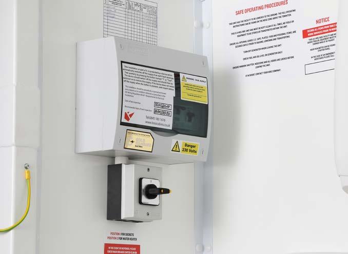
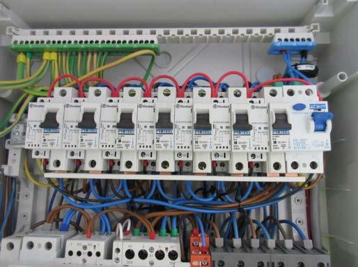
The distribution board is usually located in the canteen area of the welfare unit. It will contain a RCD Main switch and Test button, and individual MCBs to protect the electrical circuits for the vehicle.
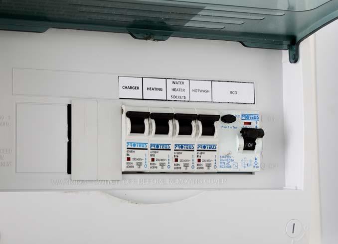
To test the Main RCD open the cover and ensure the RCD paddle is in the “ON” position. Press the TEST button, the paddle will move to the down “OFF” position and power will be cut to all circuits. If this does not happen, the RCD is faulty and the electrical system should not be used until rectified by qualified personnel.
To reset the RCD or any MCB push the paddles to the “ON” position.
Operation & Maintenance Manual
8 – Maintenance
97
Test Button On
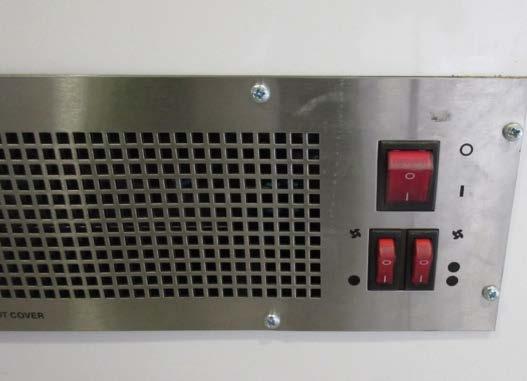
8.5.1B FUSE BOX CHECK ECO ULTIMATE
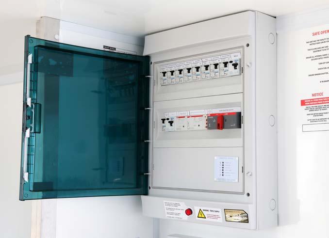
According to BS7671 IET Wiring Regulations 18th Edition, the fuse box in your cabin should be tested every six months.
The distribution board is usually located in the canteen area of the welfare unit. It will contain a RCD Main switch and Test button, and individual MCBs to protect the electrical circuits for the vehicle.
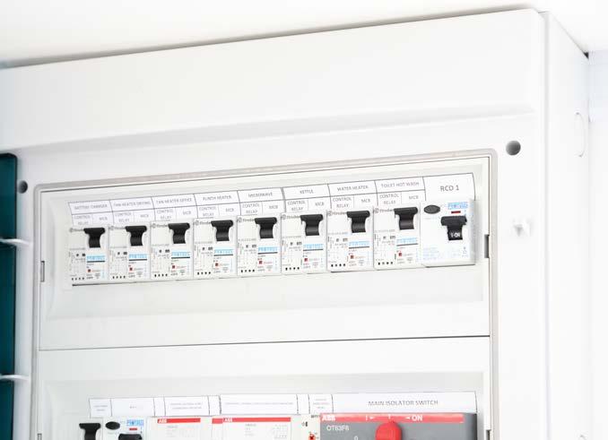
To test the Main RCD open the cover and ensure the RCD paddle is in the “ON” position. Press the TEST button, the paddle will move to the down “OFF” position and power will be cut to all circuits. If this does not happen, the RCD is faulty and the electrical system should not be used until rectified by qualified personnel. To reset the RCD or any MCB push the paddles to the “ON” position.
Operation & Maintenance Manual
8 – Maintenance 98
8.5.2 ILMS TEST BOX PROCEDURE ECO ULTIMATE
This instruction shows the electrically skilled or instructed person how to use the ILMS test box in order to fully test any ECO ULTIMATE specified cabin.
Before Testing:
• Ensure that test equipment is in good working order, with current calibration.
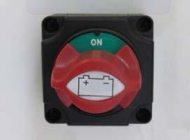
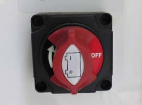
• Make sure the cabin is turned off at the Cabin Power Isolator switch.
• On the RedBox generator, operate the emergency stop. Follow these instructions in order:
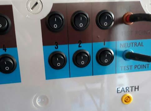
CONNECTION OF TEST BOX TO ILMS BOARD
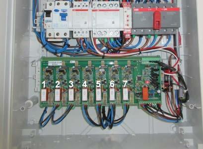
1. Remove distribution board front.
2. Disconnect ILMS board plugs, ensuring that the plugs are numbered correctly with circuit 1 furthest right, going through to circuit 7 furthest left.
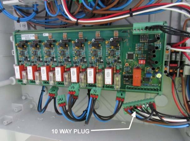
3. Disconnect 10 way plug from ILMS board.
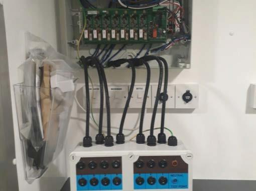
4. Connect test box to tails from inside distribution board.
5. Connect earth from test box to earth terminal in distribution board.
Operation & Maintenance Manual
8 – Maintenance 99
DEAD TESTING – 1. CONTINUITY OF CIRCUIT PROTECTIVE CONDUCTORS
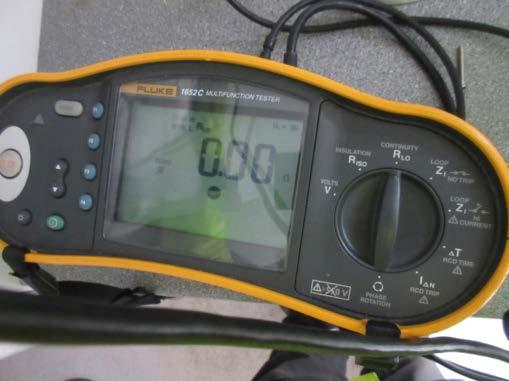
a. Turn on test equipment and select continuity.
d. Now place test leads between live and earth.
e. Record the reading for R1 + R2 on the schedule of test results.
f. Repeat for all circuits, recording the associated R1 + R2 results.
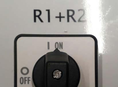
b. On test box, turn rotary isolator to R1+R2.
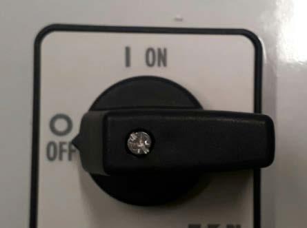
g. Return rotary switch to off position once tests are complete.
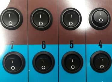
c. On rocker switches turn live and selected circuit on.
Operation & Maintenance Manual
8 – Maintenance 100
DEAD TESTING – 2. INSULATION RESISTANCE

a. Ensure all switches, at point of use, are off within the unit.
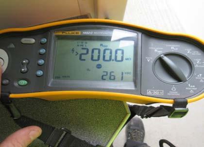
d. Complete insulation resistance tests using the test plugs on the box, record reading on schedule of test results.
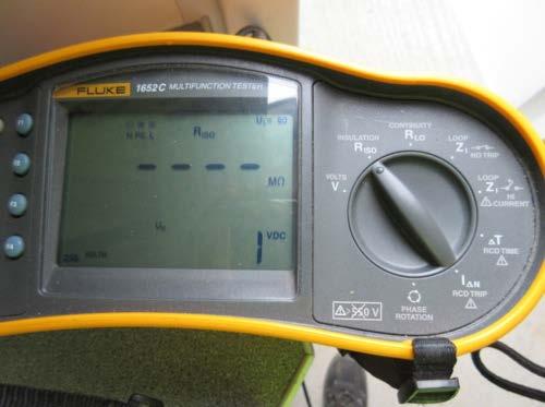
b. Select ‘insulation resistance’ on test equipment.
On completion of dead testing, unplug all leads from test box and replace onto ILMS board in distribution board.
c. Place test leads on to the test box.
LIVE TESTING – 1. RCD FUNCTIONAL TESTING
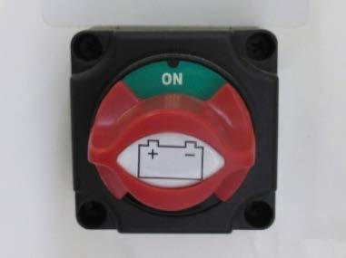
a. Turn on cabin using Cabin Power Isolator and reset the generator emergency stop.
b. Open all MCBs on top din rail of but leave the RCD closed.
c. Turn on the plinth heater. The system will call for the generator to start, but because the MCBs are open it cannot detect 230V and will not close the contactor but will allow the generator to produce 230V.
d. Select RCD test mode on the testing equipment.
Operation & Maintenance Manual
8 – Maintenance 101
e. Place test leads on:
i. Live – load side of RCD Live.
ii. Neutral – load side of RCD neutral.
iii. Earth – earth bar at the top of the distribution board.
f. Perform tests and recommend results for the RCD trip time. The disconnection time required is a maximum of 0.4 seconds. During testing the generator RCD might trip, and will have to be reset before continuing testing.
g. Once test on distribution board RCD have been completed, place test leads on supply side of RCD in order to test the Generator RCD.
h. Perform tests and record results for the generator RCD trip time. The disconnection time required is a maximum of 0.4 seconds.
i. Switch off the plinth heater, then generator will run for up to a minute then shut down.
j. Close all MCBs on distribution board.
k. Turn off cabin isolator.
Operation & Maintenance Manual
8 – Maintenance 102
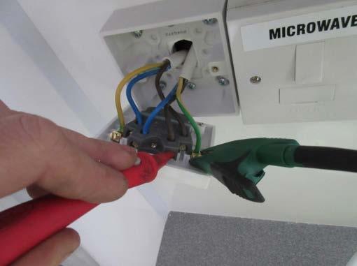
ZS TESTING
a. Open all covers of the switches using 230V within the unit.
b. Turn on cabin using Cabin Power Isolator
c. To start the generator, on the selected circuit turn on the equipment at point of use.
d. Place test probes on corresponding conductors on the load side of the switch.
e. Perform test and record the Zs result for the circuit.
f. Perform this test on all circuits and record associated Zs values.
g. When the tests are complete, replace all covers.
h. The 10A circuit breaker used on the cabin are Type B. The maximum permitted Zs 3.50 Ohms.
i. The 6A circuit breakers used on the cabin are Type B. The maximum permitted Zs is 5.82 Ohms.
j. If the Zs value of a 16A circuit is above the required maximum of 2.18 ohms the following can be applied to permit the installation to be compliant despite the Ze being higher than the typical maximum of 0.8 ohms as defined in the On-site Guide for BS 7671:2008 (2011) which in turn pushes the Zs above that required in table 41.3.
i. Referring to 411.3.2 – Automatic disconnection in case of a fault, 411.2.2.1 and 411.3.2.2, Table 41.1 the TNS system should be protected by a protective device (RCD) with a maximum disconnection time of no more than 0.4 seconds.
ii. Referring then to 411.5.3 where an RCD is used for fault protection, the following conditions shall be fulfilled:
1. The disconnection time shall be that required by Regulation 4.11.2.2.2 or 411.3.2.4, and
2. Ra x IΔn ≤ 50V
Where Ra is the sum of the resistances of the earth electrode and the protective conductor connecting it to the exposed conductive parts (ohms) Note: where Ra is not known, it may be replaced by Zs. Where IΔn is the rated residual operating current of the RCD The requirements of this regulation are met if the earth fault loop impedance of the circuit protected by the RCD meets the requirements of Table 41.5.
iii. The maximum earth fault loop impedance (Zs) for non-delayed RCD’s to BS EN 61008-1 and BS EN 61009-1 for UO of 230V (see Regulation 411.5.3) with a rated residual operating current of 30mA is 1667 ohms (Zs). Therefore, as long as the Zs for the 16A circuit breakers is less than 1667 ohms the circuit passes the test.
iv. Figures for Zs result from the application of Regulation 411.5.3 (1) and (2) above. Disconnection must be ensured within the times stated in Table 41.1
v. Therefore, the disconnection time required from Table 41.1 using a TN system with AC 120V – 230V is a maximum of 0.4 seconds.
vi. For the circuit to pass the test, Ra x IΔn must be calculated and achieve ≤ 50V,
vii.Perform the Ze test and record results. It is recognised that this installation, when connected to its generator as the source of supply has a Ze value higher than the 0.8 ohms stated as the typical maximum value of earth fault loop impedance due to the characteristics for the generator.
Operation & Maintenance Manual
8 – Maintenance 103
ZE TESTING
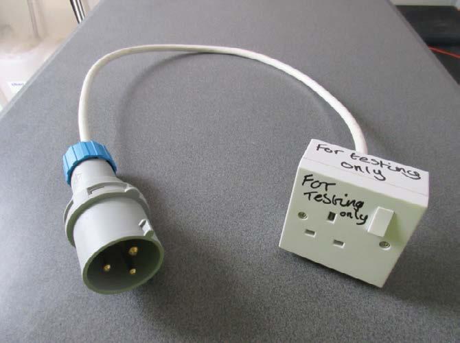
a. For this test you will need a 32A industrial style plug wired to a 13A 3 pin domestic style socket, referred to as ‘32A test lead’ in this instruction.
b. Unplug the blue supply plug from the side of the RedBox generator and plug in 32A test lead.
c. Turn on cabin using Cabin Power Isolator.
d. Turn on plinth heater in canteen. This should start generator, but not supply voltage to distribution board.
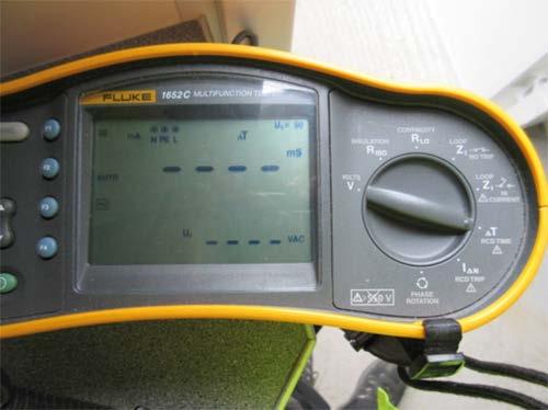
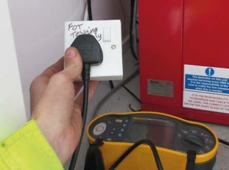
e. With the generator running, plug in test equipment into generator using adaptor.
Operation & Maintenance Manual
32A Test Lead
8 – Maintenance 104
The test equipment plugged into generator using adaptor