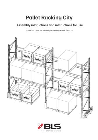
Pallet Racking City
Assembly instructions and instructions for use
Edition no. 6 ©BLS – Brännehylte Lagersystem AB. 251024
![]()
Assembly instructions and instructions for use
Edition no. 6 ©BLS – Brännehylte Lagersystem AB. 251024
Read the entire manual before starting assembly. Follow the directions in the manual to make sure the product complies with current standards.
The purpose of these assembly instructions is to facilitate correct installation and to inform of risks and how to avoid them. Bear in mind that the instructions are for your safety and the safety of others.
Use the assembly instructions and instructions for use in conjunction with:
* assembly
* regular inspections (together with the periodic inspection template)
* taking corrective action as directed
Each installation must be fitted with a load sign located in a clearly visible place.
Perform regular checks to ensure the technical safety of the pallet racking. Information about pallet racking inspections are available on our website www.blsab.se.
Parts of the installation instructions and instructions for use refer to the Swedish Standard SS-EN 15635:2008 - Steel static storage systems – Application and maintenance of storage equipment. If necessary, the purchaser or user can obtain the above standard from SIS. See www.sis.se for further information.
Links for downloading BLS installation instructions & instructions for use can be found at www.blsab.se
If in doubt, or for further information, please contact Brännehylte Lagersystem: CONTACT US
Telephone
Email Website
Postal address
Street address
+46 370 30 50 00
info@blsab.se www.blsab.se
P.O. Box 12, SE 335 04 Hillerstorp, Sweden
Brännehylte Lagersystem AB
High Chaparral
SE 335 96 Kulltorp, Sweden
List of supplied fasteners
* Applies to C90
** Applies to C110
*** Applies to C120
M8×20 /30/ M10×20 part 111308-1-20-7 part 111310-1-20-7
Self-drilling screw 5.5×19 part 111616-4-19
M8 / M10 nut with flange part 111308-7-0-7 part 111310-8-0-7 M10 nut lock part 111310-6-0-7
Fasteners not included
M10×75/105/110 75 mm - part 111310-1-75-7*/** 105 mm - part 111310-1-105-7***
* Applies to C90
** Applies to C110
*** Applies to C120
The client/user must make sure the floor is able to bear the relevant loads.
Pallet racks must be anchored to the floor to prevent the uprights from moving when mechanical handling equipment is used in or near warehouse fixtures.
Correct rack assembly is essential for a safe structure. Assembly must be carried out professionally and in accordance with these instructions.
Beam safety pin part 111021
Distance tube 30/43 30 mm - part 111056*/** 43 mm - part 111056-43***
Base plate C90 - part 90-001*/** C120 - part 120-001***
Multi-Monti 10×80 part 111009-14
Expander bolt M10×90 part 111009
Distance Spacer
150 mm - part 111005
200 mm - part 111210-200
250 mm - part 111210-250
300 mm - part 111210-300 or
* Leveling Plate
1 mm - part 111076-90-1
2 mm - part 111076-90-2
3 mm - part 111076-90-3
**/*** Leveling Plate
1 mm - part 111076-120-1
2 mm - part 111076-120-2
3 mm - part 111076-120-3
Multi-Monti M10×60
Drilled hole Ø8
Drill depth 65 mm, cleaned hole
Max. Mounting thickness 10 mm
Multi-Monti M10×80
Drilled hole Ø8
Drill depth 85 mm, cleaned hole
Max. Mounting thickness 30 mm
Multi-Monti M10×100
Drilled hole Ø8
Drill depth 105 mm, cleaned hole
Max. Mounting thickness 50 mm
Max torque impact wrench
Multi-Monti M10, 600 Nm
Multi-Monti M10×100
Drilled hole Ø8
Drill depth 115 mm
Max. Mounting thickness 50 mm
Multi-Monti M10×140
Drilled hole Ø8
Drill depth 155 mm
Max. Mounting thickness 90 mm
Always use concrete screws and anchoring compound when installing on asphalt.
H = Mounting thickness L = Drill depth
Drilled hole diameter T = Thickness of concrete slab


1. Installing upright base plates (A)
2. Locate the braces according to the bracing diagram on pages 6-7. (B)
3. Place distance tubes at single braces at the ends of the frame. (C)
4. Tighten the braces.
1. Level the floor.
Starting from the highest point, adjust any unevenness using levelling plates. (D)
2. Erect a starter bay and install beam safety pins in the beam safety holes. (E)
3. Check that the frames do not exceed the specified tolerances with regard to incline.
The incline in relation to plumb may not exceed 3 mm per metre in depth and laterally.
4. Install 2 distance spacers between each frame pair. Install distance spacers where braces meet.
Use 2 distance spacers per bay for bays up to 7 metres. If the bay is bigger than 7 metres, use a 3rd distance spacer.
Distance spacers are only fitted for double racks. (F)
Horizontal push-through protection
Vertical push-through protection
Always use self-drilling screws in the outermost hole of each beam level. (J+K)
J K I H I J K H
Use vertical push-through protection with floor anchors on pallet racking with only two load-bearing levels. (I)
Frame barrier, single rack
Frame barriers, double rack
Floor bracket Profile End caps
4 pcs Multi-Monti 10×80 /Expander bolt M10×90
2 pcs M8×30
At least one load sign per rack must be clearly visible.
Inspection and service according to SS-EN 15635
SS EN-15635 is the European standard for steel static storage systems and outlines guidelines for the installation, operation, and maintenance of the storage system.
Assembly inspection
Inspect the assembly before putting the pallet racking into service to confirm compliance with the assembly instructions.
Regular inspection
Storage systems must undergo a visual inspection every week or at other regular intervals to ensure that no load-bearing parts are damaged. A formal written report must be prepared for the regular inspections.
Periodic inspection
Storage systems must be inspected annually by an individual with the requisite technical knowledge.
The inspection, along with specified risks and measures, must be documented in a report and submitted to the person responsible.
Damage to the storage systems
Damage to load-bearing parts in the racking must be remedied immediately by replacing the part as this poses a safety risk. Other parts may be repaired.
For more information, refer to SS-EN 15635 Steel static storage systems - Installation, operation and maintenance
Checks during regular inspections
1. Check that there are beam safety pins on all sides of the beams.
2. Check that there is no damage to the beams, uprights, and bracing members. If necessary, replace damaged components immediately as they pose a safety hazard.
3. Check that there is a load sign and that it refers to the relevant racking configuration. At least one sign must be clearly visible.
4. Check to ensure the pallets and beams are not overloaded.
5. Check that there is an upright protector on the frames and uprights, and that the forklift aisles are correctly sized.
6. Check to ensure the floor is not damaged and that the racking is anchored to the floor.
The incline in relation to plumb may not exceed 3 mm per metre in depth and laterally.
In the event of damage of a local nature (dents, kinks, tears and cracks), always replace the parts.
The maximum residual vertical deformation (after unloading from the maximum load) must not exceed the beam length L/200. Maximum residual horizontal deformation L/400.
Uprights may deform outwards a maximum of 5 mm/m in relation to plumb along the length of the racking, and a maximum of 3 mm/m along the depth..
Brace deformation must not exceed 10 mm per metre. This applies regardless of the direction of deformation.