
Reconfigurable Manufacturing System Factory Base
Dissertation

CHANG – CHUAN, CHEN (Benjamin)
11/05/2022
Supervisor: Simon A Pope
Abstract
In the 21st Century, companies need to allow their manufacturing production system to be rapidly response to market changing and customer objectives. Therefore, using reconfigurable manufacturing system (RMS) could allow different objective of manufacturing configurations to be produced by addition removal orupdating ofnewmachinetools orcomponent. In this report,byreviewing theeffects that reconfigurable manufacturing system has bring to current industry, our team wished to build an RMS factory base which enables the workstations in Factory able to be reconfigured. To begin, a Modular factory testbed that implement the idea of RMS has been review. Based to the review, the mechanism forthefactorybasehasthenbeendesigned.TodeterminedhowtheRMSfactorybase wouldaffect theproduction line, a MATLAB GUI calculator has then been designed to determine the time for a single block movement to be done. With the calculator and theimplementation of anair-conditioner assemblyline, 3 different floor baselayout model has been built. In that case, the effect of reconfiguring production line can be observed and determined.
1.1 Background and Motivation
In the 21st Century, manufacturing companies are facing frequently unpredictable market changing because of competition over worldwide, which include rapidly new products replacement or constantly varying of product demand. Nowadays companies need to allow their designed manufacturing system products to be rapidly response to market changing and customer objectives, rather than produce highquality product with low price [1]. Meanwhile, the production line systems need to be upgradable so thatitcouldincreasecapacityandchangeablefunctionallyneeded.Torespondtothisrequirement,using reconfigurable manufacturing system (RMS) would be a great solution. Comparing with traditional production lines, an RMS has better reconfigurability which allows the different objective of manufacturing configuration by addition, removal or updating of new machine tools or component [2].
With the personal working experience in an air-conditioner factory, I have noticed that swapping large mechanical product toward each workstation in the factory would require a lot of human labor force. By the inspiration of the n puzzle, we wished to implement the idea of n puzzle into a reconfigurable manufacturing system. The production line has been reconfigured into movable blocks that can load different manufacturing configurations, for instance, machine tools, production goods, or product. Under the movable blocks, we designed a conveyor belt system, building in the base of the factory, which allows to swap the movable blocks. In this case, the production line could be easily reconfigured and rebuilt
1.2 Aims and Objective
1.2.1 Aims
In the current industry, the production process has usually been fixed formally. However, companies might need to change the production line to fit the criteria or objective to produce the customize or latest-version product.
The project is looking forward to reconfiguring the production line into moveable blocks of manufacturing configurations, which can be moved by the conveyor belts built in the base of factory. In this case, goods and products and be easily swap in the factory, and the production line can be easily reconfigured or rebuild.
1.2.2 Basic Objectives
• Review on the importance of the reconfigurable manufacturing system
• Review on the production line which use manufacturing system and the movements of goods/products in a factory.
• Review on the assembly line of an air-conditioner in practical
• Review the floor space reconfiguration and mechanism to make possible goods/products movements
• From the result previous reviews, design and model a conveyor belt system which form the base of a reconfiguration of the production line
1.2.3 Advanced Objectives
• Using the developed model to simulation a simple reconfigurable production line and analyse its behaviour compare with formally fixed production line
• Using information on a relevant specific production line example, extend the simple simulation to a more realistic application and analyse its performance in terms of suitable metrics.
• Investigate sustainable maintenance on conveyor belts and moveable blocks
1.3 Project Management
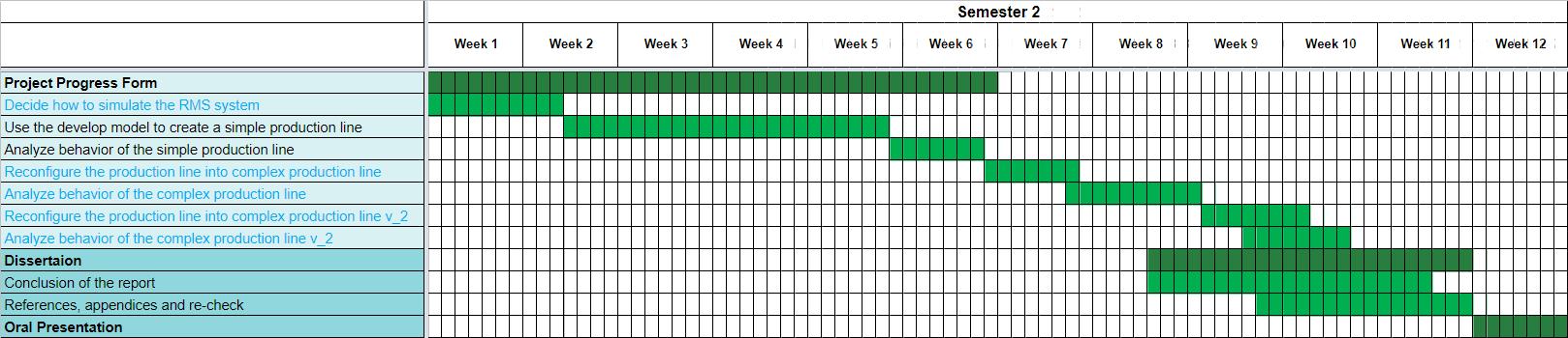
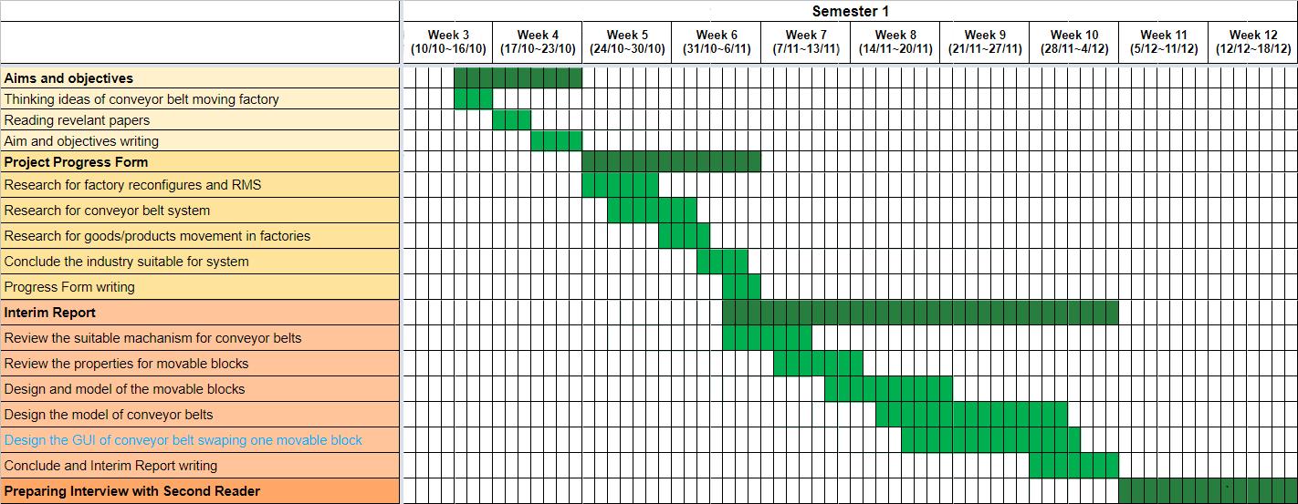
In the first semester, the project focusses mostly on reviewing the RMS and conveyor belt system, then the mechanism designing of the system. However, figuring out a solution for the graphical presentation of RMS factory is much more difficult than expectation. To make the system easier to simulate, the MATLAB GUI calculator has then designed to focused on a single movement of movable block. This is the reason why the modelling system change to a GUI app.
For the second semester of the project, the graphical presentation of RMS factory has then been firstly working through. Then the project would focus on the model creation of a simple production line and analyse the behaviour of it However, during the model creation, we noticed that the layout of floor base would significantly affect the production rate. We have then decided to focus more on how much would the production rate be affected by another 2 different floor layout models. This is the reason why the sustainable issues have then been changed to the analysis of 2 different models.
To establish the RMS system needs a lot of early-stage investment. Firstly, a regular factory needs to be provided by manufacturers. Depending on the space area, our team can then take over to estimate how many factory floor-base blocks can be built in the factory. A single conveyor belt block would require an undercarriage for Bulldozer excavator, a IWYHG Series High Speed Hydraulic Motor, 2 mini excavator rubber tracks, and 4 Photoelectric infrared detectors. On the other hand, a single movable block would be built with a 2.4 ��3concrete. The price of each component can be found in the following Table 3:
According to the calculation in Table 3, the price for building a single conveyor belt and movable block would be £3723.65. Depend on how much blocks allow to build in a factory, for example, the model that we have built has 20 blocks, the total price for early-stage investment would be 3723.65×20= £74473. Although the price does not low, the promote of production can make profit to the manufacturers to cover up the early-stage investment in long term planning. After the initial equipment have been established, testing the most suitable production line for the model needs a few days of calculation and decision. Since then, the model is well-prepared for production.
To summarize, the project in this report would focus on reviewing how reconfigurable manufacturing system affects the current manufacturing industries, what do conveyor belt system focus on while building, the current implementation of RMS application in testbed, and the workstation for the target air-conditioner assembly line would build. By designing a MATLAB GUI calculator to determine the time for the movable platform to finish a single movement, the application can use to determine the time taken for shipments to be done with different layout of the air-conditioner assembly line. Moreover, by comparing different floor base models for the reconfigurable air-conditioner assembly line, we wished to find how much impact the RMS factory floor base could bring to current- fixed production lines.
To build the RMS factory base, some base knowledge needs to be review in the first place. This section would focus on reviewing how do RMS affects the current manufacturers, what are the bases while building a conveyor belt system, how would a current RMS testbed work, and what workstations would an air-conditioner assembly line require.
2.1 Importance of RMS
Changing manufacturing environment characterized by aggressive company competition globalize and the rapid changes in processing technology requires to create production systems that could be easily upgrade, moreover, be able to add in new technologies and new functions can be readily integrated. The following conditions would require a new manufacturing approach for the next generational manufacturing system [4]:
• Able to launch new product models to be undertaken very quickly, and rapid adjustment of the manufacturing system capacity to market demands
• Rapidly integration of new functions and easy to process technologies into existing systems
• Highly adaptation to variable quantities of products for niche marketing. [4]
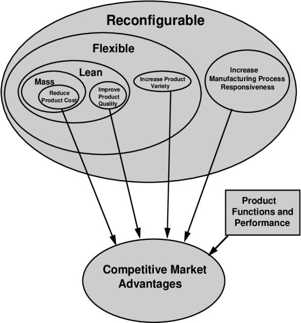
The economic goals for various manufacturing paradigm can be viewed in Figure 1. By the comparison through different manufacturing paradigms, it could tell that Mass production focused on reducing production cost, while Lean manufacturing emphasis on continuous development of the product. Flexible manufacturing system (FMS) seems to bepossible to manufacture various products on the same system, sometimes it would be limited because of highly price building [4]. With the new type of manufacturing system, which we usually called reconfigurable manufacturing system, would allow system to be flexible not only to produce various types of components, but also changeable for the system on its own. RMS system usually created by basic process modules, which would be rearranged
quickly and reliably. These systems will be opened-ended, so it would be continuously improved by the latest technology. Moreover, it can reconfigure rapidly to allow future product changeset rather than directly replacement [5].
The development of RMS can be divided into the following six characteristics [6]:
1. Modularity – machines, controls, tools, or other configuration within the manufacturing system which can be added, removed, and switched for other items with relative ease.
2. Integrability – at both the machine and the system level, manufacturing companies need to integrate modules rapidly and effectively.
3. Customization – the system had enough flexibility so that it could be upgraded or added new modules.
4. Convertibility – the exist systems and designs can transform into new production lines.
5. Scalability – by rearranging the manufacturing system, the system would be able to add new products.
6. Diagnosability – the system would be able to automatically read and analyse defects, errors, or related problems.
The fundamental aim of RMS is to design a set of manufacturing configures which is cost-effective and rapid response to change for the market demands. The design and rapid ramp-up of RMS would be the new manufacturing paradigm, which provides exactly the functionality and capacity needed, exactly when needed [7].
2.2 Review of conveyor belt system
A conveyor belt is a widely used mechanical handling system, which used efficient and effortless process to move supplies, materials, and components that saves on time and energy. The mechanism of the conveyor belt includes two motorized pulleys with the conveyor material looped over them. On the other hand, the pulleys operate at the same speed and move in the same direction to activate the motion of the conveyor belt. Conveyors blet usually applicated in material handling industries for transporting bulk materials, packets, and parcels [8] [9]. Moreover, conveyor belts system can use used for product manipulation, such as sintering, part to assembly, or component washing [10].
The range and usage of conveyor belts depends on different industrial settings and applications. The efficiency of conveyor belt systems assists in improving productivity, saving on laboratory costs, and decreasing lead time. There are several ways to make the conveyor belt fit into an operation to increase efficiency. However, while each system is designed to fulfill different requirements, the following requirements need to be considered prior before installing a convey system [11]:
• Space: Manufacturers need to examine the available space to determine system design. This step requires identifying clearances, interaction points, obstructions, or any possible areas that could interfere with material movement.
• Loading Capacity: Overloading a system can damage it or cause it to stop during its operation. While designing the conveyor belt system, factors that influence the load capacity are overall length and bed width as well as the drive system.
• Speed: The unit of a conveying system moving speed is measured in feet per minute (fpm). The average speed is 65 fpm, which is how fast a person moves when carrying a 50 lb. package.
• Configuration: Conveyor systems come in a wide variety of shapes, designs, sizes, and forms. Each system is designed to fit a special application, it would be impossible to cover all the different configurations. In this case, adding additional configures should not have too much restriction or limitation in a conveyor belt system.
• Driver: Drive systems can have single or variable speeds depending on their design. It usually has a system of gears run by a motor. Variable speed drives have become popular for modern conveying since they allow for changes of material flow.
• Safety: Conveying systems are preventative measures to protect employees from moving or lifting bulky materials. It was regulated by the Occupational Safety and Health Administration (OSHA) and must meet government safety requirements. All conveyor manufacturers are aware of the regulations and adhere to them.
2.3 Review of current RMS Application
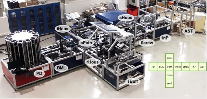
A study in 2018 models a modular factory testbed which focus on the transformability and modularity under a distributed shop-floor control architecture. The major products of the testbed are laboratoryscale electric endodontic handpieces, electric toothbrushes, and portable battery chargers that are assembled by 10 main workstations as shown in Figure 2 [12].
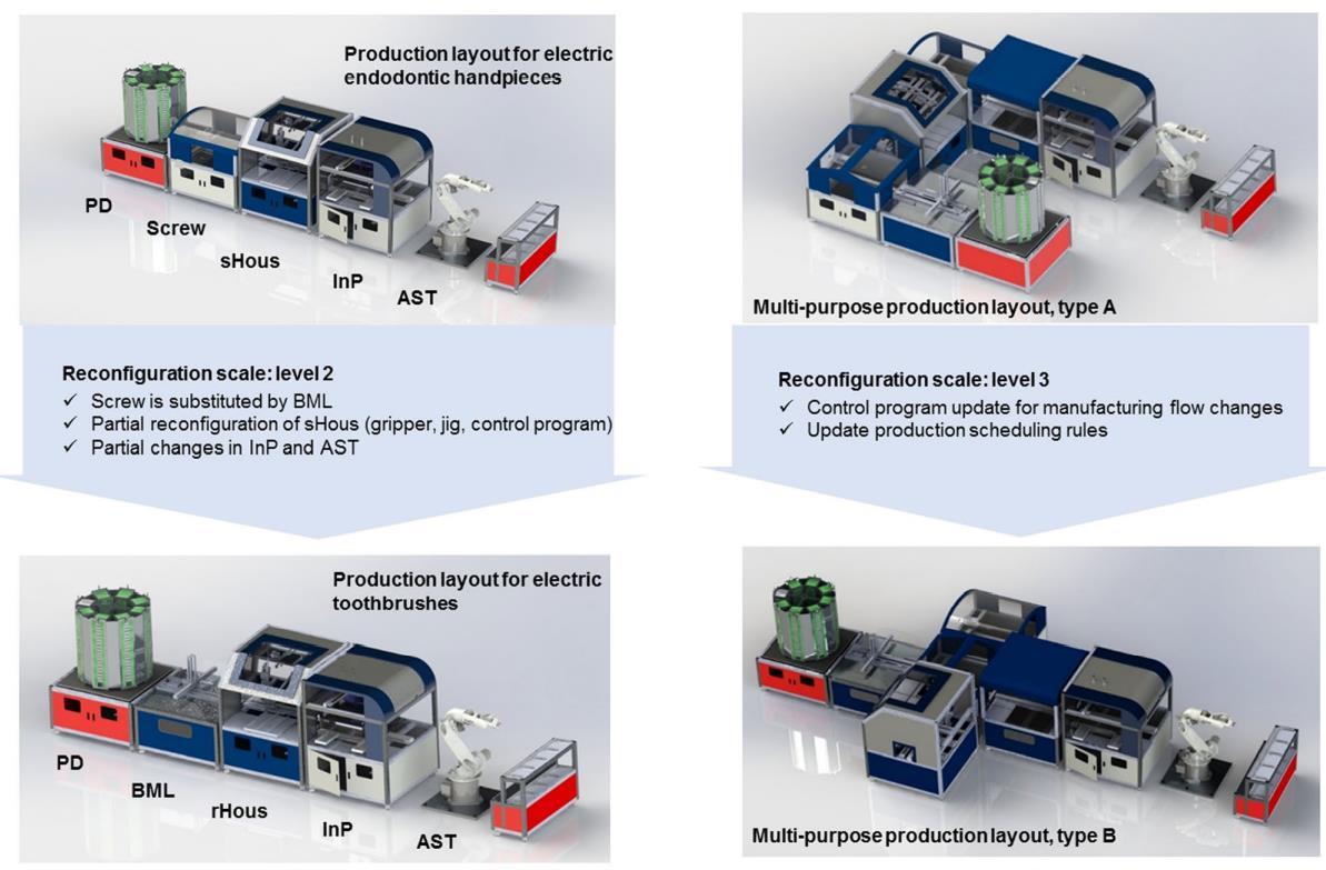
The layout of production line would be able to reconfigure according to the target product. For example, in left side of Figure 3, to build an electric endodontic handpiece, the workstation for screw and sHous is required. However, while building the electric toothbrushes, the production line can be reconfigured by swapping Screw to BML and sHous to rHous. On the other hand, in the right side of Figure 3, the production has been reconfigured to reduce the footprint in the factory.
2.4 Review the assembly line of an air-conditioner
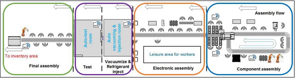
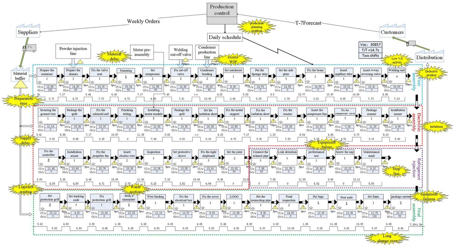
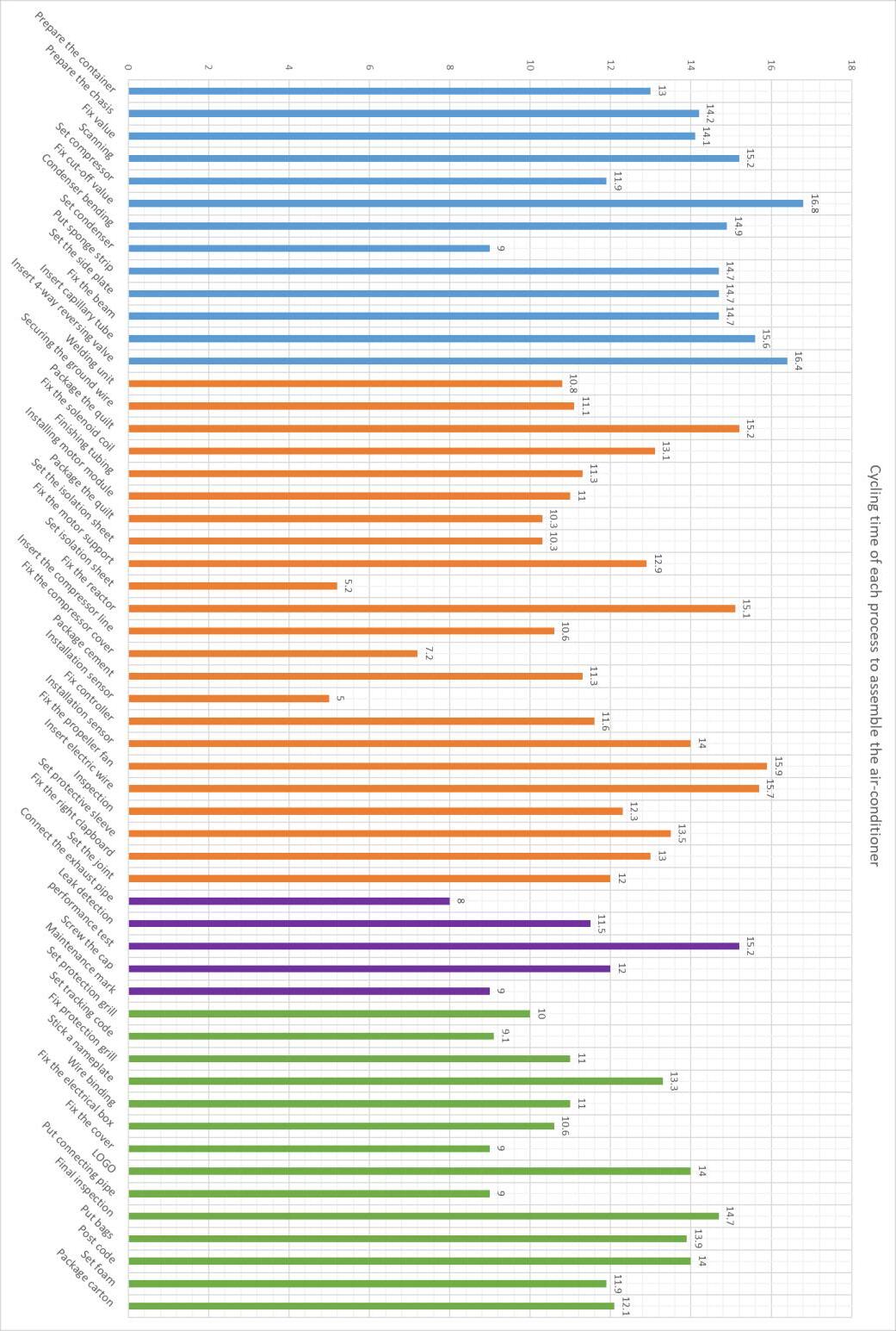
The assembly line of air conditioner in the factories has 55 main processes which can be observed in Figure 4 and Figure 6. However, it could be separate into 4 main areas - component assembly area, electronic assembly area, refrigerant inject & testing area, and final assembly area. In the component assembly workstation, the RFID tag would be firstly scanned. After that, the compressor, value, and the condenser would be installed one after another. In the end, the pipe would be weld. In the electronic assembly workstation, the fan unit, electric box, sensors, and fenders would be installed in succession. In the refrigerant inject & testing workstation, after the pipe joints have installed, the air-conditioner should be vacuumized, and the refrigerant would then injected. The machine would then test for its performance. In the final assembly workstation, the covers would be installed, logo would be paste, the machine would be final test, and package up with carton boxes. The layout of the production line can be observed in Figure 5 [13].
To summarize for this section, by reviewing the past dissertations, the basic knowledge for establishing an RMS can be understood. The RMS factory base would be built on a hugeconveyor belt system which able to reconfigure the movable workstation blocks in the factory. Moreover, by the reviewing of airconditioning assembly line, it could be implemented and reconfigured to fit the RMS factory base.
Chapter 3 – Main technical
After some basic knowledge for the system have been reviewed, the design for the RMS Factory Base has begun. This section would explain the concept of building the RMS Factory Base. By picking up the suitable mechanism components, we have then coded a MATLAB GUI calculator to determine the time taken for a single movable block to be swap.
3.1 The Concept of RMS Factory Base
According to the current RMS application which reviewed in Section 2.3, the machine tools which used are designed test bed configures which could manufacture various types of small products. However, while producing larger size industrial equipment, such as cars, air conditioners, or lathe, the reconfiguration process would be difficult. These items are normally customized based. However, the procedure for manufacturing these machines is usually the same pattern. The components of these machines are also bulky to be moved, so there would be forklifts shuttling in the factory, which may be extra inconvenient and dangerous.
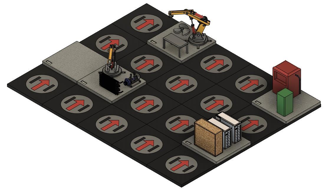
The idea of the RMS factory base would focus on reconfigure each working station in a traditional factory. Firstly, the movable blocks are floor based configures, which allows not only machine tools, but also humans to stand on. In this case, the whole working station could be able to swape toward the factory. The coworker can then fix, assemble, or operate the machine tools directly on the movable blocks. Moreover, while the movable blocks are easy to reconfigure, the goods, components, and products can also be able to swaptoward thefactory,andtheriskofusing forkliftorcranewould reduce. The 1st edition CAD sketching concept of the RMS factory base is shown in Figure 7.
3.2 Mechanism design
Building a conveyor belt system that enable to swap the whole workstation is not easy. The first, and most important issue we need to face is the loading capacity. The weight range of different machine tool is magnificent. Some basic tools, such as drilling machine (200 kg), or belt grinder (160 kg) would not be too hard to lift or move. However, for large size industrial level tools, for instance, shaping machines (500~2315 kg) or CNC lathes (1800~3500 kg), the swapping movement would be difficult even using cranes [14].Notevenmachinetools, rawmaterials, suchas solidwoodboard,copperpipe,orgalvanized sheet steel, are also heavy to move while the usage amount is large. However, the maximum load weight of flat conveyor belt is around 90 kg (200 Pounds) [15], which means that the current conveyor belt system would not be suitable for this idea.
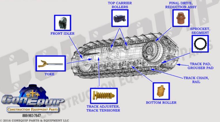
A remodel undercarriage of excavator can used to the horizon or vertical movements of the floor base conveyor belt system. With the supporting of the top carrier rollers and bottom rollers, which geared by the Sprocket Segment, the loading capacity can be increase to around 8~10 tons, the same as the weight oftheexcavator[16].Thepartdiagram of excavatorundercarriagehasbeenshownin Figure 8.However, the material of the chain would be better change to rubber (1.16) to increase the coefficient of friction between the movable blocks.
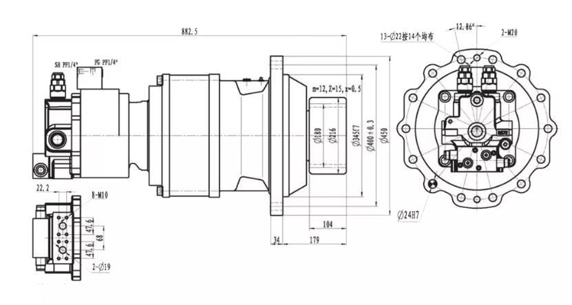
To enable the floor base conveyor belt system to be rotate, a hydraulic motor has then been selected to placein thecenterofeach conveyor belt. IWYHG Series HighSpeed Hydraulic Motor showedin Figure 9 has been selected since it can elevate up to 25 tons. In that case the hydraulic motor would be able to bear the whole workstation while lifting.
For the material of the movable blocks, concrete then be selected after consideration. Although concrete is heavy, as the maximum loading capacity is increased to 10 tons, swapping a 500~600 kg concrete block would not be too difficult. The diameter of each moveable block is 4��×4��×015��. The mechanism design of the moveable block is shown in Figure 10
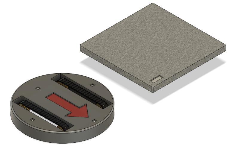
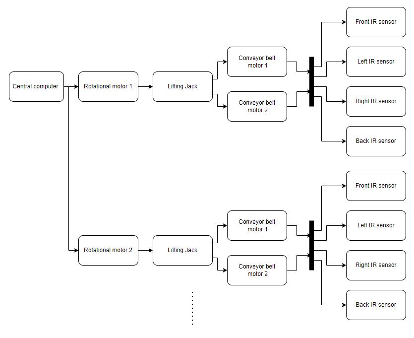
For the conveyor belt, the mechanism design can be viewed in Figure 10. Except the gear system, there would 4 IR sensors which used to detect the direct the position of the movable blocks. At the bottom center ofthe conveyorbelt,therewouldbean electrical lifting jack, whichwould liftthemovableblocks up, while the rotational motor is changing the direction. All the Conveyor belts would connect to a central computer, which is able to control the direction and movement of each conveyor belt. The schematic diagram can be observed in Figure 11.
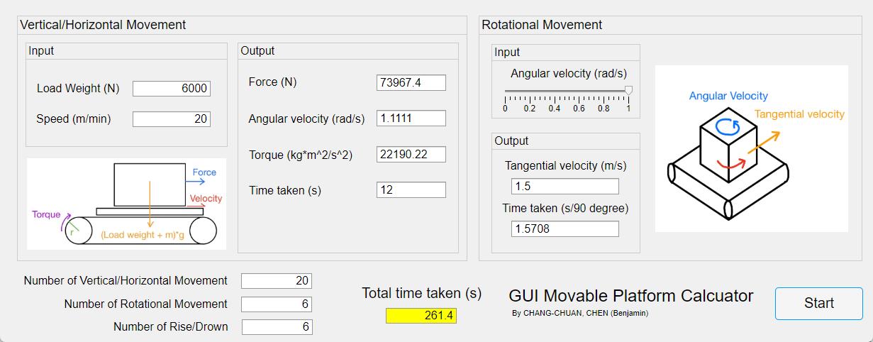
3.3 MATLAB GUI calculator
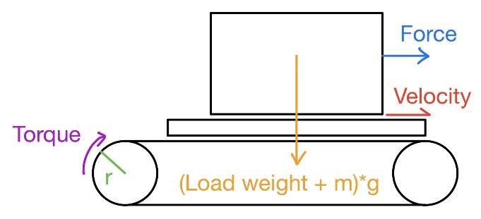
To simulate the movement of the conveyor belt floor base, the GUI in MATLAB has been created to calculate the data of conveyor belt for swapping the movable blocks. The following parameters have been set for the first place: the mass of the movable block is 500 kg, the coefficient of friction of rubber is 1.16, the radius of conveyor belt gear is 0.3m, the radius of rotational plate is 1.5m, and each of the movable block has a dimension of 4×4 - meter square.
3.3.1 Vertical/Horizontal movement
By implementing the following equations, the data of a single Vertical/Horizontal movement can then be determined:
* The reason for using m/minas thespeed unit is because the regularlyunit usedin conveyor belt system is feet per minute (fpm). However, the scale difference would be too large if we choose to use m/s.
3.3.2 Rotational movement
By implementing the following equations, the data of a single Rotational movement can then be determined:
3.3.3 Total time taken
As the time taken for a cycle of vertical/horizontal movement and rotational movement has been determined, the number of vertical/horizontal movement, rotational movement, and rise/drown need to be determined according to the flow and layout of factory floor base. After that, the total time taken for transporting can be calculated.
����ℎ = Number of Vertical/Horizontal movements
������ = Number of Rotational movements
����/�� = Number of Rise/Drown
By combining all the equations above, the MATLAB GUI calculator showed in Figure 14 has then been designed, and the result can be used to compare which layout of factory base would be best suitable for the production line.
To summarize this section, our team wished to establish the RMS factory by building a conveyor belt system which allowed to swap 4×4 meter squared movable workstation block. Since the current conveyor belt could not be able to load the movable workstation block, we decided to design a single conveyor belt by remodelling the undercarriage of excavator for Vertical/Horizontal movements and implementing a Hydraulic Motor in the center for Rotational movements. While all the single conveyor beltshavebeenconnected toacentral computerthatcontrolsthedirectionand movementofeachconveyor belt, the system have been built. On the other hand, by implying the parameters for Vertical/Horizontal movements and Rotational movement, the time taken for the movable block transporting can be determined by a MATLAB GUI calculator
Chapter 4 – Floor base layout modelling
Insection3.3,sincethetimetakenforswappingthemoveableblockcanbedeterminedbythecalculator, we wished to observe how much time could the RMS system save after the production line has been reconfigured. The air-conditioning assembly line which has been reviewed in section 2.4 would then be used for reconfiguring into 4 workstations – Workstation 1 (component assembly), Workstation 2 (electronic assembly), Workstation 3 (refrigerant inject & testing), and Workstation 4 (final assembly). By placing the workstations into different layout models, we would then calculate the time taken for 3 shipments to build the air-conditioning and suggest which reconfigured model is the most suitable one. The following parameters have been set for the first place: The load weight would be set as 6000N, the speed for Vertical/Horizontal movement would be 20 m/s, and the angular velocity of Rotational movement would be set as 1 rad/s.
4.1 Simple production line
The simple production line has been reconfigured based on the original 4 workstation According to Figure 6, the time taken for each workstation can be calculated in the following Table 4:
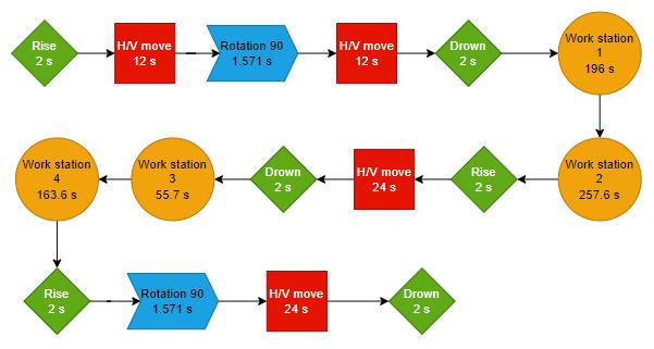
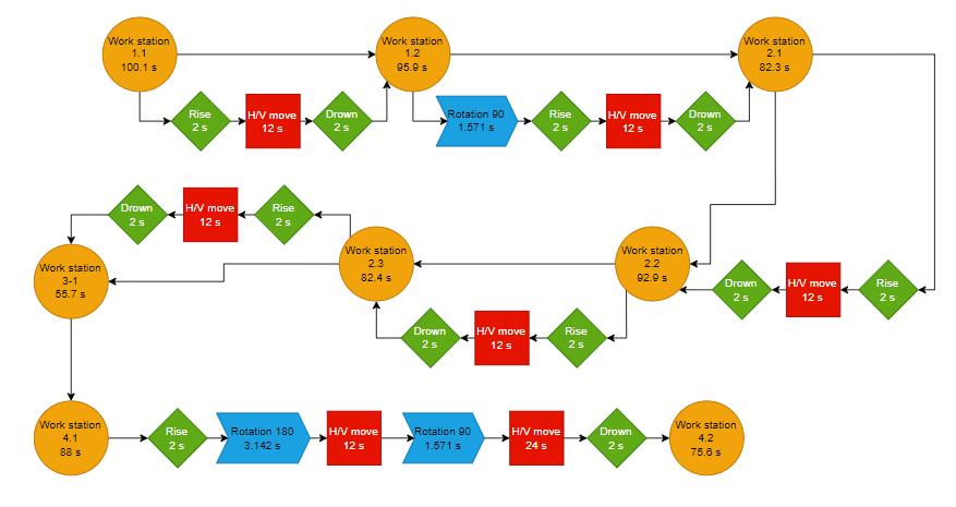
The route and layout of floor base can be observed in Figure 15. Firstly, the moveable block loading with materials would move toward the block between Workstation 1 and Workstation 2. Since Workstation 2 has finished, the moveable block would swap toward the block between Workstation 3 and Workstation 4. After the has done in Workstation 4, the finished product would be move to the exit. The flow chart has been determined in Figure 16. Moreover, the time chart of the first 3 shipments can be calculated in Figure 6
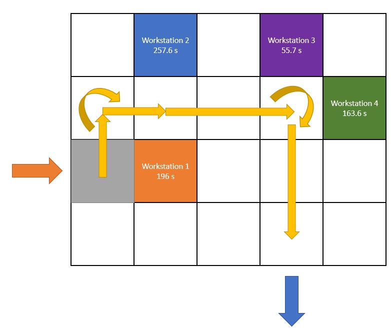
According to the result in Table 5, the production rate would be slightly increased while the shipment has increased. However, by observing the layout of floor base in Figure 15, there were too many unoccupied floor bases, which would waste a lot of footprints in the factory floor. On the other hand, the heading supply should be delay 453.6 seconds to make sure that the shipment would not be delayed by the workstations. To summarized, by setting up the workstations, the air-conditioner assembly line can be allowed to apply into the RMS factory floor base system. However, if the layout of workstation can be changed or reconfigured, the time taken for a shipment may decreased, so that the assembly line would be more efficiency.
4.2 Complex production line
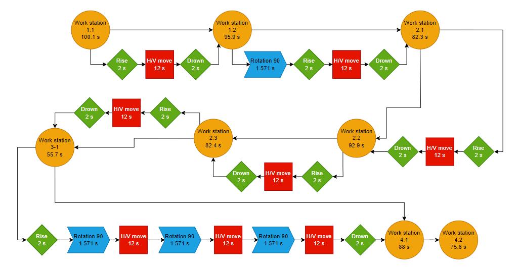
According to the result of simple production line in section 3.4.1, to make the assembly line more efficient, the layout of each workstation needs to be reconfigured into more complex production line. According to Table 3, the cycling time for each workstation is unbalanced, which would make the heading supply force to delay if the shipment flow would not be stuck. To decrease the time of delaying, the cycling time for each workstation need to be targeted to reach around 80 to 100 seconds. In that case, Workstation 1 would be separate to Workstation 1.1 and Workstation 1.2. Workstation 2 would be separate to Workstation 2.1, Workstation 2.2, and Workstation 2.3. Workstation 4 would be separate to Workstation 4.1 and Workstation 4.2. On the other hand, since the cycling time of Workstation 3 (55.7s) is much shorter than the other workstations, a second Workstation 3 need to be estimate to diverse the shipment flow. The time taken for each workstation can be calculated in the following Table 6:
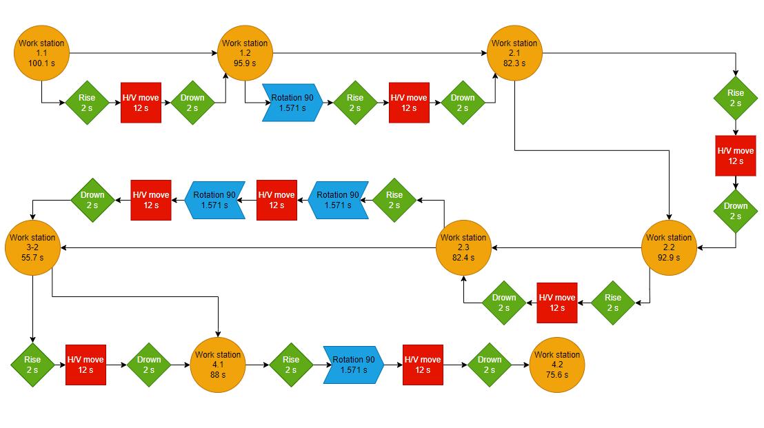
The layout and the 2 shipment routes of complex production line could be observed in Figure 17 and Figure 19. For the first route, the moveable block loading with materials would firstly placing in front of Workstation 1.1. Since Workstation 1.1 has been finished, the moveable block would be swap toward Workstation1.2,2.1,2.2,2.3,&3-1oneaftertheother Aftertheprocessin Workstation3.1hasfinished, the movable block would move toward the block between Workstation 4.1 and Workstation 4.2. This shipment would be done after the work has done in Workstation 4.2. On the other hand, for the second route, after Workstation 2.3 has finished, the moveable block would be swap to Workstation 3-2, and then to the block between Workstation 4.1 and Workstation 4.2. The flow chart could also be observed in Figure 18 and Figure 20
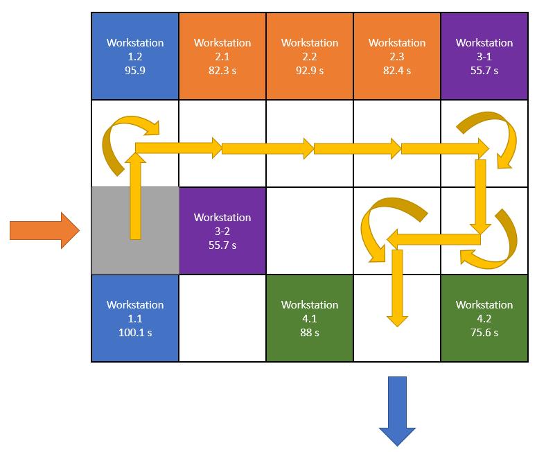
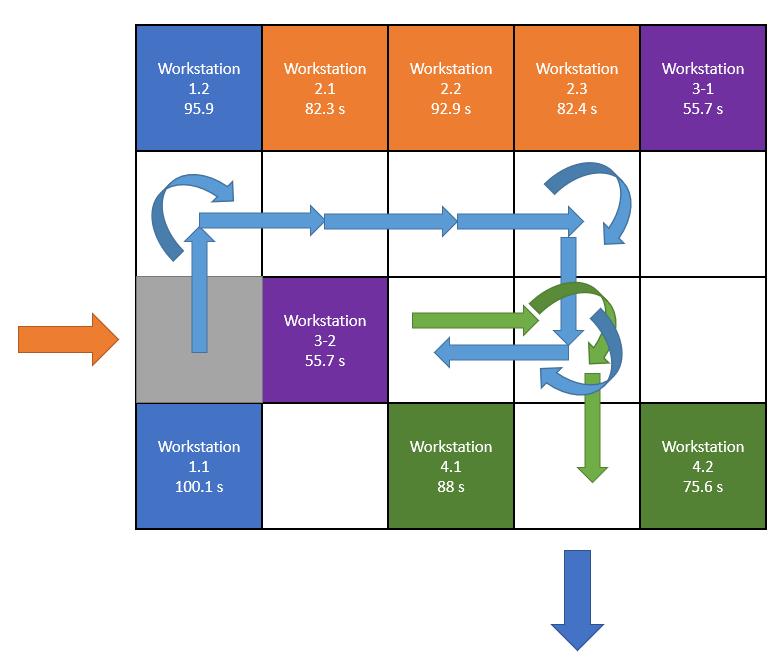

By comparing the layout and route in Figure 17 and Figure 19 with Figure 15, the occupation of floor bases has increased, which can present more comprehensive potential of the RMS factory floor base. On the other hand, by comparing the results in Table 7 and Table 6, it could determine that although the 1st shipment for the complex production line would take about 40 seconds longer because of more workstation separation, the 2nd and 3rd shipment would be finished much quicker than the simple production line as soon as the Workstation 3-1 and Workstation 3-2 have diverse the flow into two different routes. In that case, the assembly line can be horizontally working, and the production rate would be significantly increased.

3.4.3 Complex production line v_2
Since the Complex production line can be implemented for the air-conditioner assembly line, we wished to observe how the reconfigured layout would affect the production rate. In this case, another complex production line model has been established, which we named as Complex production line v_2. The shipment route and floor base layout of Complex production line v_2 can be observed in Figure 21 and Figure 23. By comparing to the original Complex production line in Figure 17 and Figure 19, the location of Workstation 4.1 has changed. In this case, after Workstation 2.3 has finished, the shipment would swap to the block between Workstation 3-1 and 4.1 for both workstations to work through, then move toward Workstation 4.2. For the second route, the route does not change but the time working for Workstation 4.1 has changed. The flow chart can observe in Figure 22 and Figure 24.

By comparing Table 8 with Table 7, it could be observed that although the production rate for the 1st shipment would be the same, the production rate in the 2nd and 3rd shipment would increase since the time ended had decreased. Since the position of Workstation 4.1 has changed, the time for the shipment keeping in Workstation 3-1 and Workstation 4.1 would increase. Parallelly, the other shipment can pass down to Workstation 3-2, and the delay between shipments would not exist. In this case, Complex production line v_2 would present the maximum potential of the RMS factory floor base. Furthermore, the more shipment passes through, the more time would be saved, and the more the production rate would increase. For long term consideration, Complex production line v_2 would be the model that can implement to the manufacturing factory to improve the original production line while the production rate increased 61.6%.