


CYLINDER HEAD
Loosening of the bolts - sequence -
Tightening of the bolts - sequence -
Tightening torque, cylinder head bolts: 88 ± 5 Nm
Technical Data
Valve clearance, cold
mm inlet & exhaust
Tightening torques: Bolts/nuts in general Thread
injection pipe injection pump
leak-off pipe
fuel injection nozzle
to fuel tank
overflow pipe
fuel pump
filter
from fuel tank
Injection nozzles - injection figures
Injection nozzle
body
washer
pin spring
injection nozzle compl. spacer
threaded sleeve
Typ/Model/Type
Benennung/Description/Dénomination
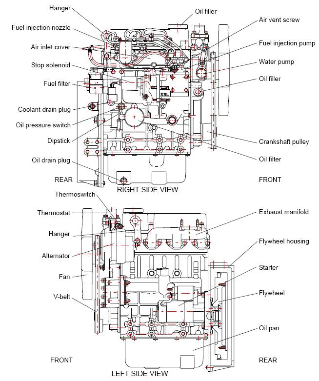
Oil circuit
oil pressure switch
main oil gallery
oil filter
pressure relief valve
oil pump
drain plug
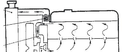
Water circuit
cooler fan
bypass hose thermostat water pump
oil screen
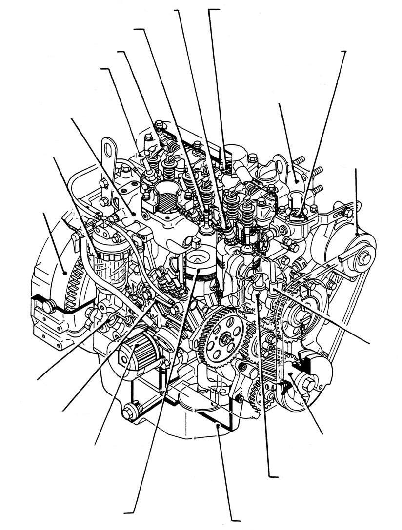
fuel filter
water pump
fuel injection nozzle oil filler plug intake manifold
oil dipstick
fuel injection pump
ventilation pump
fuel system
oil drain plug
coolant drain plug
starter
exhaust manifold
engine serial number
oil pressure switch
flywheel housing
thermostat fan
oil pan oil filter
alternator
v-belt pulley on crankshaft
CYLINDER HEAD
Tightening order of bolts
Tightening torque of cylinder head studs: 118 ± 5 Nm Technical
Tightening torques: bolts / nuts, general
Fuel feed
Fuel filter
• Slacken the ventilation plug (A) of the fuel filter (B) by means of an open end wrench.
• Put a clean cloth around the ventilation plug (A) to collect the escaping fuel, then operate the feed pump (C) as shown in the illustration.
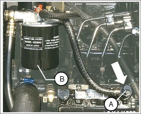
• The ventilation plug (A) is to be closed when the fuel escapes from the ventilation without bubbles.
If the fuel pump valve is dirty and the fuel cannot be fed through the fuel filter, the ventilation plug as well as the feed line of the fuel filter are to be dismounted and cleaned with compressed air.
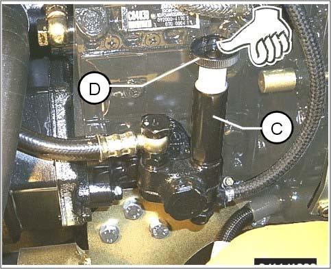
• To unlock the fuel pump cover (D), turn it to the left.
• Operate the fuel feed pump (C) approximately 20 times, then turn the cover (D) to the right and lock.
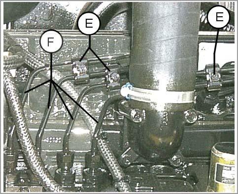
Remove fuel lines
• Remove pipe clamp (E) from the injection lines (F). Unscrew lines (F) at the injection pump and at the injection nozzles (G).
• Unscrew the drain oil lines (H) at the injection nozzles (G) by slackening the nuts (J)
Mount protective caps to protect the fuel system against dirt or foreign particles at the pump and injection nozzles !
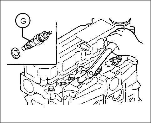
Removal of the injection nozzles

• Screw out the injection nozzles (G) of the engine by means of a socket wrench.
Remove the injection nozzle seals with a wire or a screwdriver and dispose of according to regulations.
Injection nozzles - injection figures
Good ⎜ ← Bad, replace → ⎜
Injection nozzle
housing washer spring pin spacer injection nozzle, cpl.
threaded sleeve
Removal of the injection pump
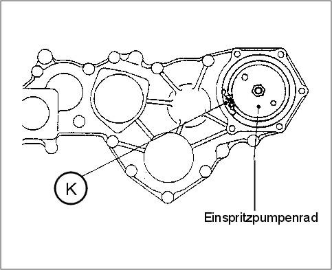
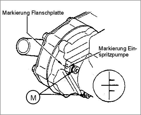
• Check the alignment of the marking on the injection pump with the marking on the flange.
• Remove the front cover of the injection pump gear.
• Make markings (K) at the idler gear and injection pump gear.
• Slacken the bolts of the intermediate flange and remove the injection pump including the intermediate flange and gear.
Make sure that the engine does not turn after the removal of the injection pump.
To remove the gear of the injection pump, slacken the nut of the gear prior to the removal of the pump.
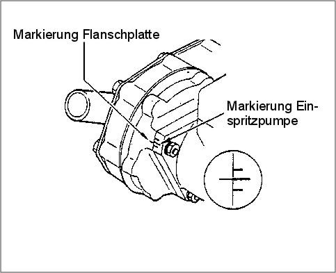
Check the injection timing
• Adjust the piston no. 1 to top dead centre. 3.800.03/01.2007
flange marking injection pump marking injection pump gear• Turn the crankshaft approximately 30° counter-clockwise, facing the engine front side (fan side). Then slowly turn clockwise up to 20° before top dead centre until the marking on the crankshaft V-belt pulley is in line with the one of the control housing.
• Remove the maintenance cover from the fuel injection pump.
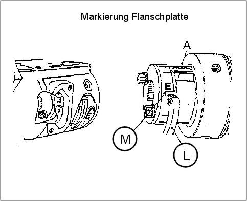
• Make sure that the flat side „A“ of the circlip aligns with marking „E“ on the setting plate. If this is alright, the injection timing is adjusted correctly.
• If the flat side „A“ is not in alignment with line „E“, the nuts holding the injection pump are to be slackened and the pump is to be turned in such a manner that the markings align.
• Hold the injection pump in that position and tighten the nuts.
flange marking injection pump marking
Engine control
The setting data of the injection system depends on the performance, speed (rpm) and specification of the engine. For the correct data, please refer to the documentation of the engine manufacturer.
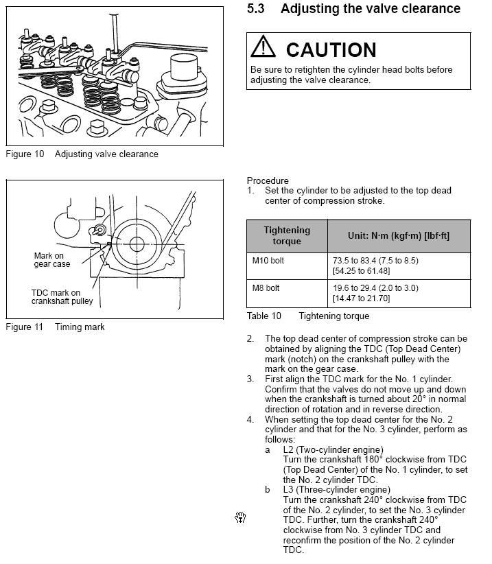
1) Adjustment of the first piston to top dead centre in compression stroke
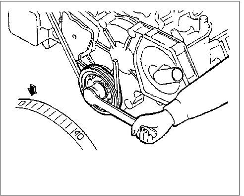
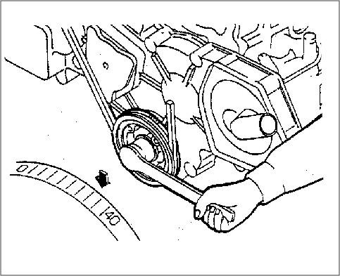
a) Turn the crankshaft clockwise (with a view of the engine front side) until the „O“ at the crankshaft V-belt pulley is in line with the marking.
b) Press the inlet and outlet rocker at the first cylinder downward. Tappets must be free.
2) Check of the injection timing
a) Remove the retainer ring of the valve holder for the first cylinder at the injection pump.
b) Dismount the valve holder (1) for the first cylinder. Remove the piston of the pressure valve (2) and the spring (3).
c) Re-mount the valve holder (1).
d) Mount the overflow pipe on the valve holder (1) for the first cylinder.
e) Turn the crankshaft until the piston of the first cylinder is 60° before top dead centre.
f) Turn the crankshaft in engine turning direction by operating the hand feed pump until the fuel flow from the overflow pipe stops.
g) Check injection timing (marking on the crankshaft V-belt pulley of the crankshaft).
3) Adjustment of the injection timing
a) If the injection timing must be changed, turn the injection pump as shown in the illustration opposite.
b) Only the setscrew for max. engine speed is sealed.
c) If this setting is checked and adjusted, please ensure that there is somebody near the engine to be able to operate the engine cut-off mechanically in case of engine overspeeding.
d) A marking unit at the injection pump flange changes the injection timing by 6° to the crankshaft angle.
Off-load min. speed (idle running speed) and max. speed setting
a) The off-load min. speed (idle running speed) as well as the max. speed of each engine are set on the test bench in the factory. The setscrew for max. speed is sealed. These settings are to be performed by an authorised workshop only.
b) After removing the leaden seals and adjusting the regulator, all visisble stops are to be sealed as though they would have been sealed by the factory.
c) It is decisive for the settlement of warranty claims whether the stop screw leaden seals are alright or not.
d) When this setting is checked and adjusted, please make sure that there is somebody near the engine in order to be able to stop engine mechanically in case of engine overspeeding.
For inspections and settings warm the engine up thoroughly until the coolant and engine oil temperatures are higher than 70°C (158° F).
3.800.05/01.2007
injection timing earlier injection timing later1) Engine start-up
a) Set speed adjusting lever to high idle running speed. Actuate starter.
b) The engine fires from a crankshaft speed of 150 min-1. When the engine is running, the speed is to be held between 800 and 1,000 min-1
c) When the engine is running with constant speed, the speed adjusting lever is to be brought into idle running position.
2) Set off-load low idle running speed
a) Hold the speed adjusting lever in offload min. speed position and set low idle running speed by means of the setscrew (2)
In case of a critical speed (speed resulting in bad engine vibrations due to torsional oscillations), a higher or lower speed range is to be chosen.
b) Engine speed increase: Turn the setscrew of the low idle running speed clockwise.
To be performed by trained and qualified personnel only:
c) In case of speed variations (fluctuations of the engine), turn the setscrew (3) of the idle running speed spring clockwise to increase the spring preload.
An excessive spring preload results in engine overspeeding with the load decreasing. Make sure that this is prevented.
3) Set max. output (capacity)
To be performed by trained and qualified personnel only:
a) Bring speed adjusting lever into full load position and load engine with its indicated output.
b) While the engine is running with constant speed, adjust the full load stop screw in such a manner that the engine achieves its indicated output.
c) If the full load stop screw is turned counter-clockwise, the capacity is reduced, and the engine speed is lowered.
If the full load stop screw is turned clockwise, the capacity is increased, and the exhaust gas values deteriorate.
This setting can only be performed on the test bench as it is sealed by the factory.
Oil circuit
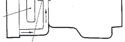
rocker arm
valve tappet
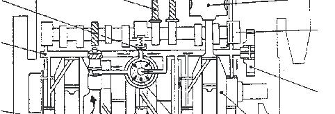

pressure valve

oil main distribution
oil pump
intake manifold
Water circuit
drain plug
piston
camshaft
control gears
crankshaft
engine oil filter
thermostat
Kurbelgehäuseentlüftung (Breether) Einspritzdüse(FuelInjectionValve)
Ventil(Valve)
Kipphebel(RockerArm)
Zylinderkopf(CylinderHead)
Einlasskrümmer (IntakeManifold)
Kraftstoffilter (FuelFilter)
Schwungrad (Flywheel)
Ölmesstab (Oil-LevelGauge)
Einspritzpumpe (InjectionPump)
Ölfilter (OilFilter)
Kolben (Piston)
Thermostat (CoolingWaterThermostat)
Auslasskrümmer (ExhaustManifold)
Generator
Stößel (Tappet)
Kurbelwelle (CrankShaft)
Nockenwelle (CamShaft)
Ölwanne (OilPan)


