WINTER 2025 EDITION
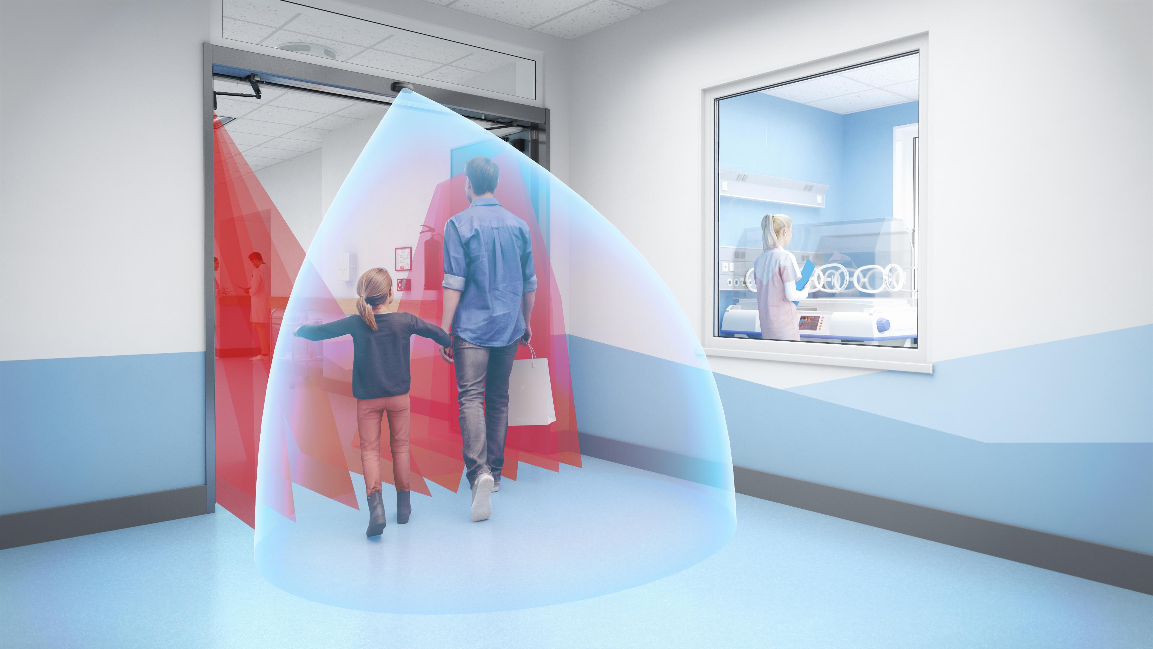
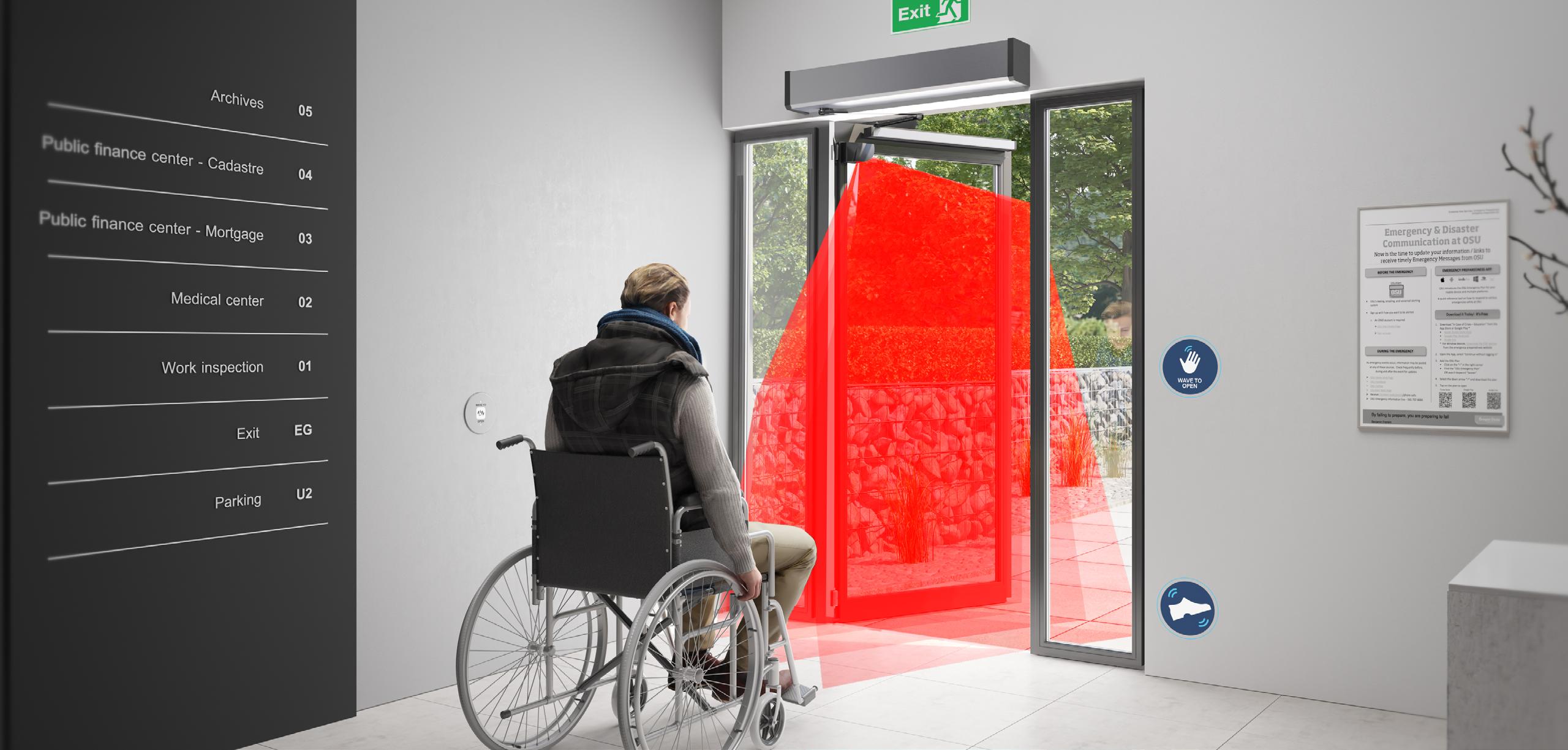
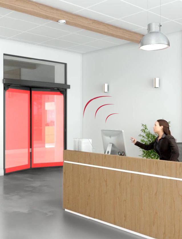
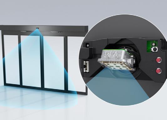
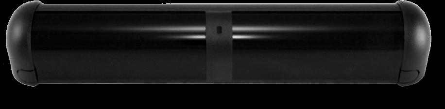
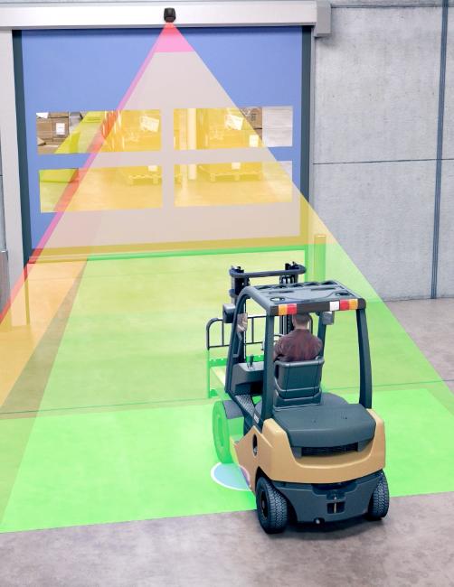
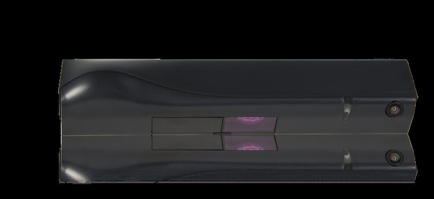
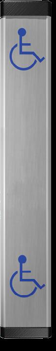
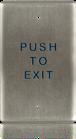
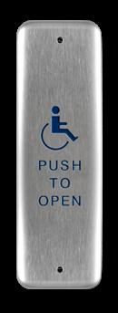
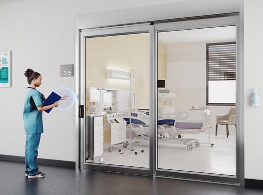
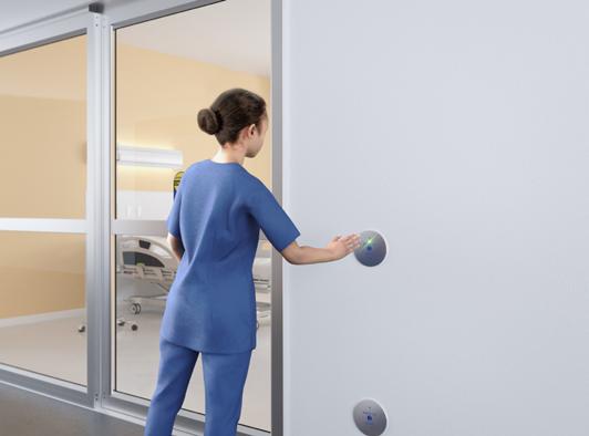
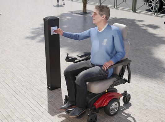
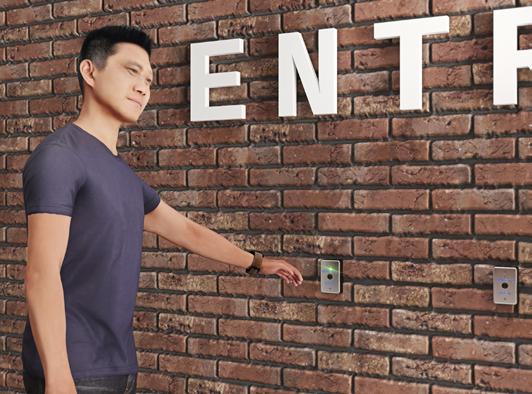
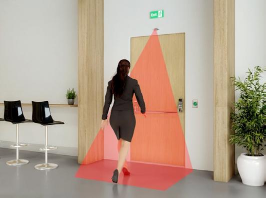
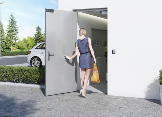
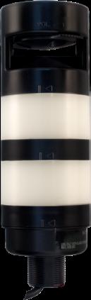
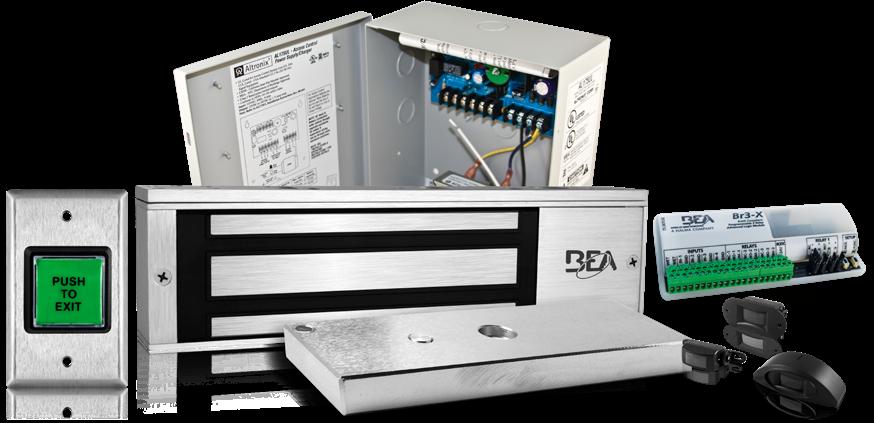
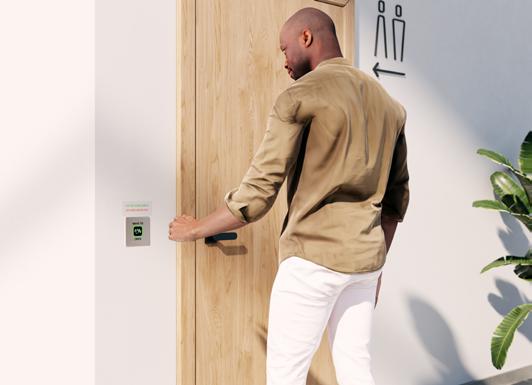
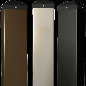
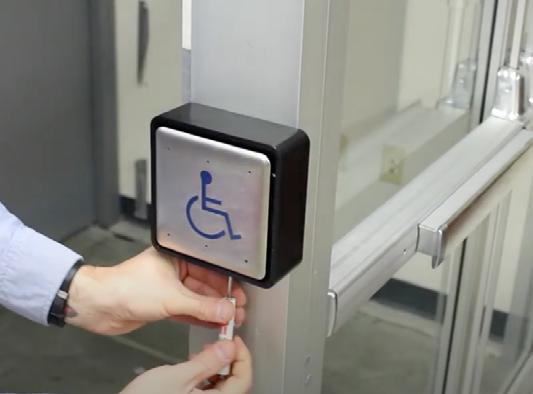
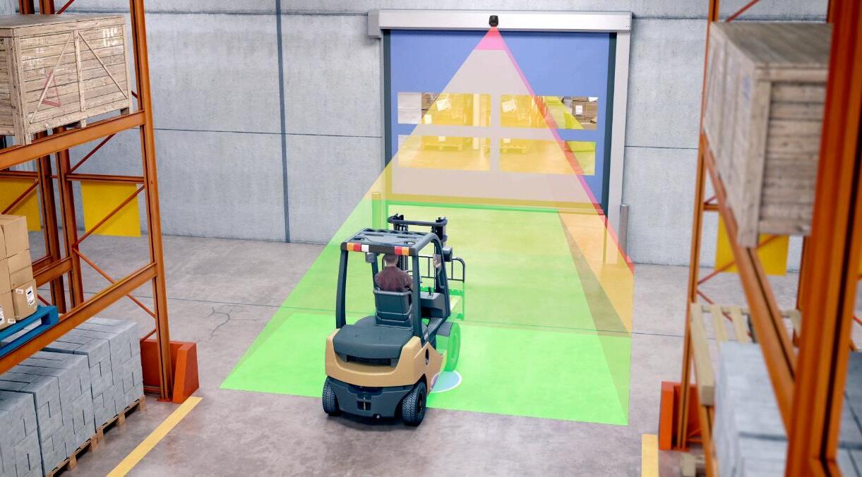
FOUR CURTAIN STAND-ALONE, DOOR-MOUNTED SAFETY SYSTEM WITH VIRTUAL PUSH BUTTON FUNCTIONALITY
READ MORE ON PAGE 29
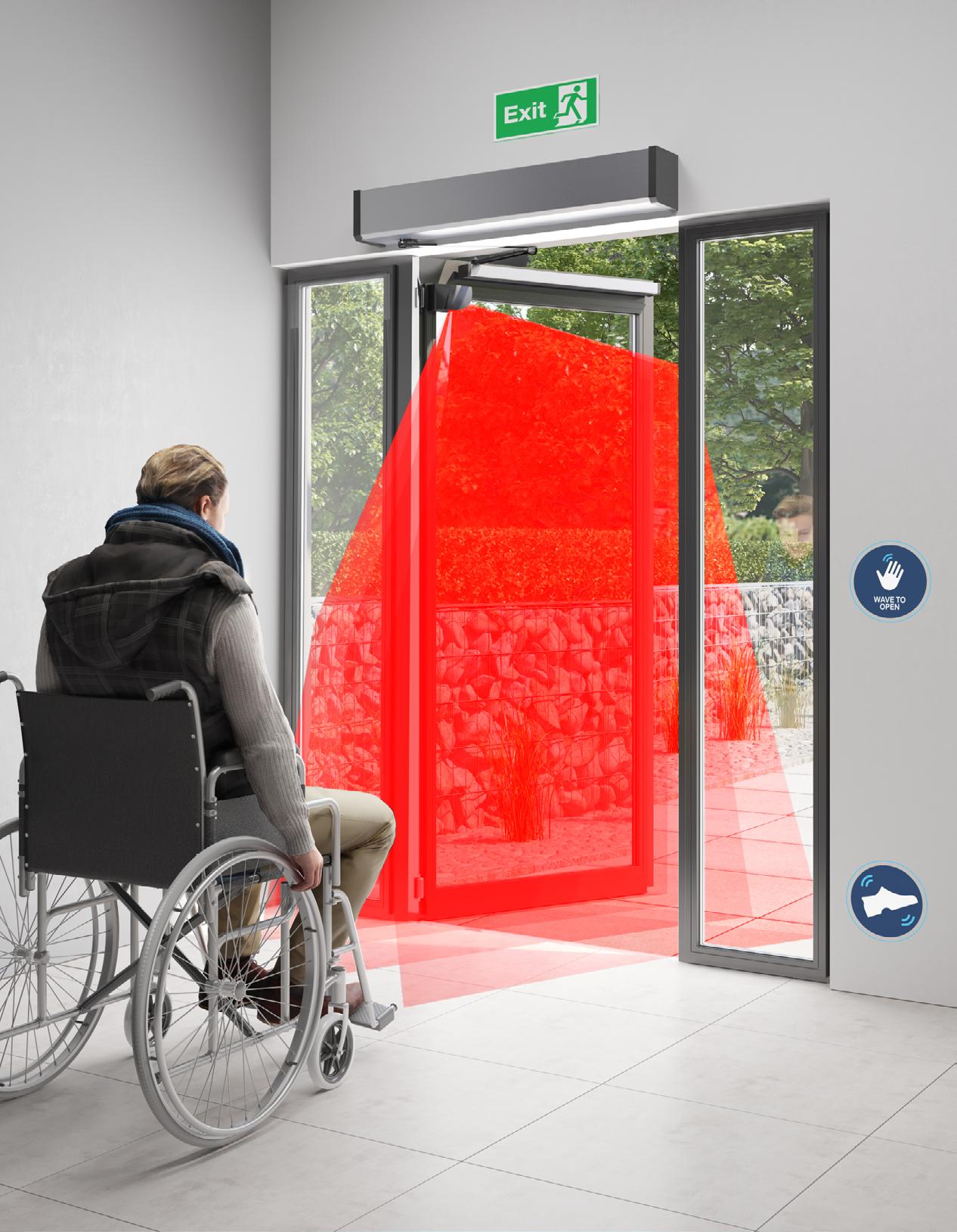
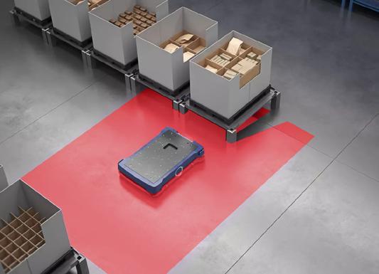
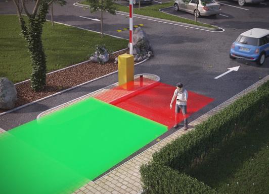
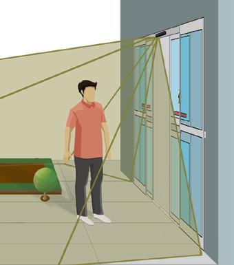
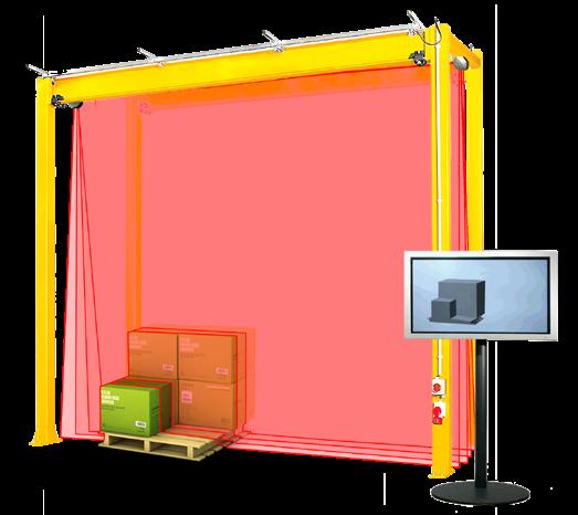
Three-Dimensional Field Coverage
3D detection field guaranteeing full-safety coverage of the opening area
LASER-based Technology
Capable of ignoring dynamic ground conditions (reflective flooring, pedi-mats, wet surfaces, etc.)
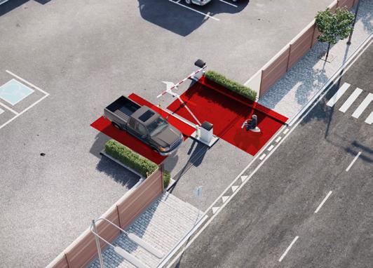
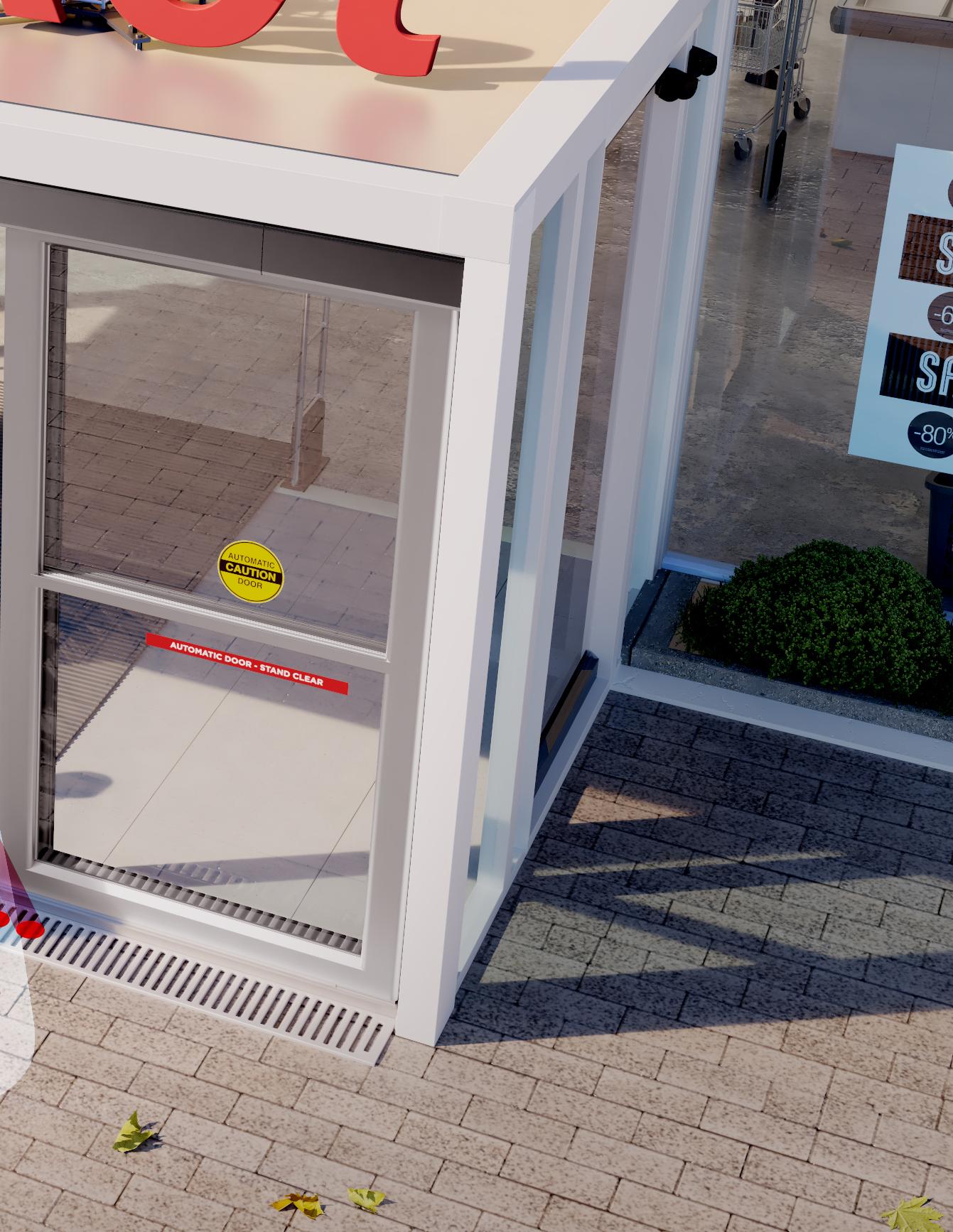
ANSI 156.19
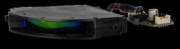
REACTIVATION
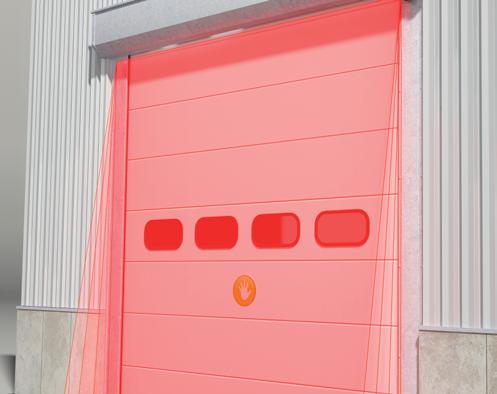
Complete door coverage with LZR-FLATSCAN 3D SW LASER-based sensor
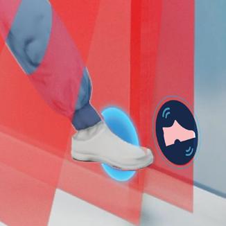
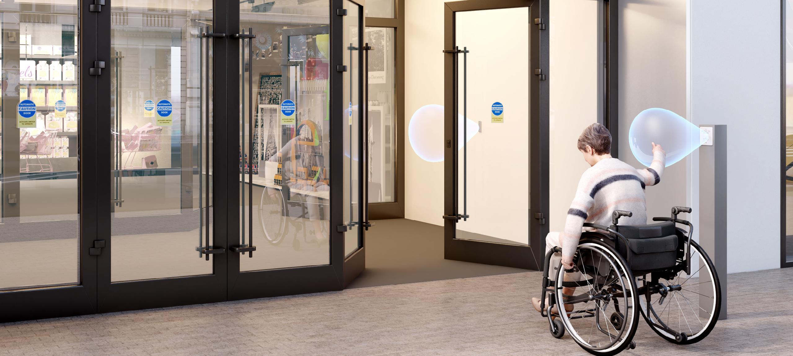
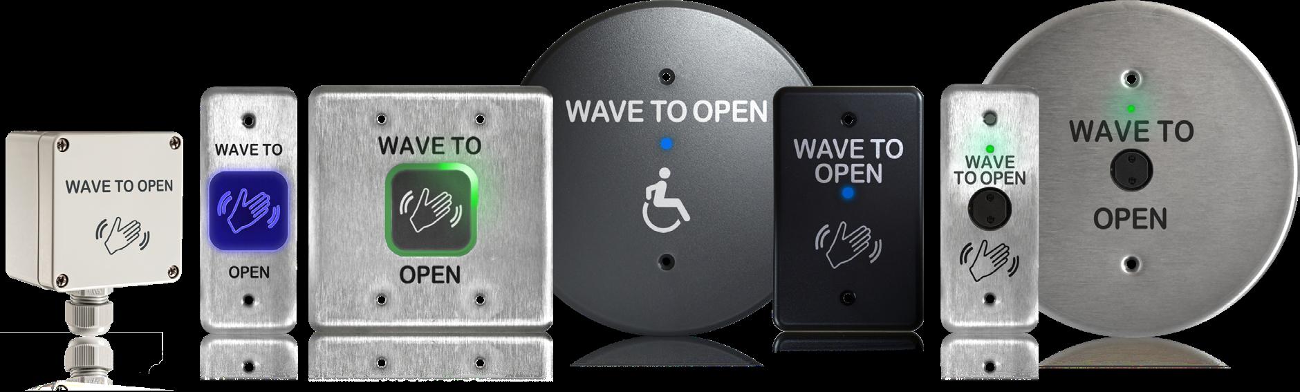
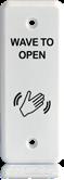
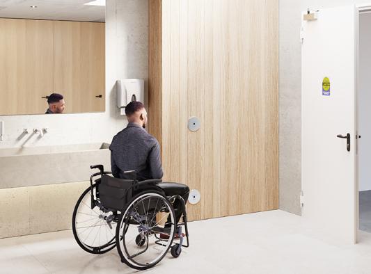
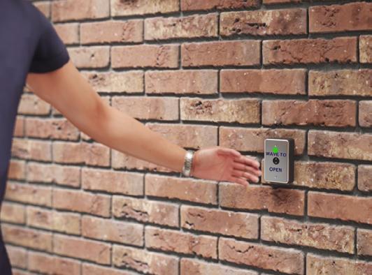
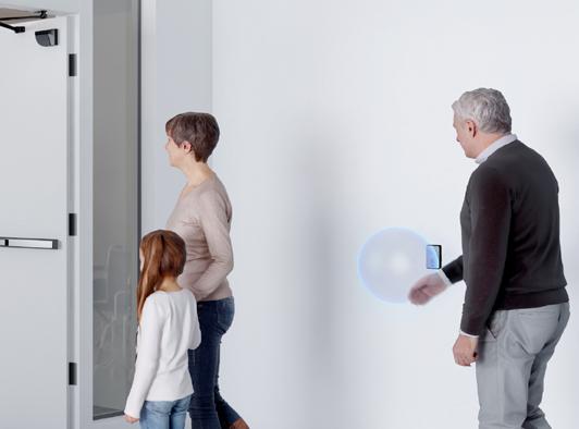
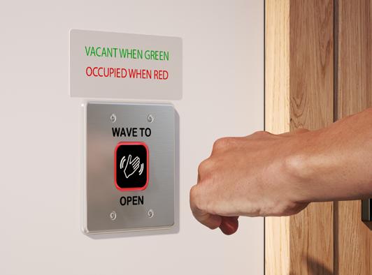
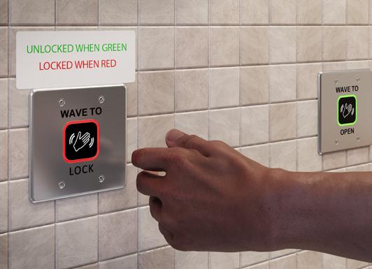
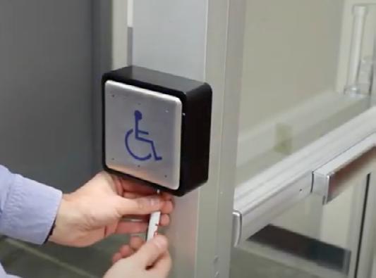
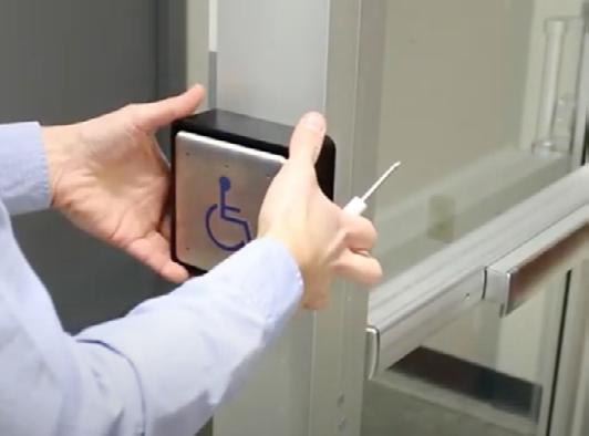
Completely Touchless
For germ-free activation, program up to two Virtual Push Buttons
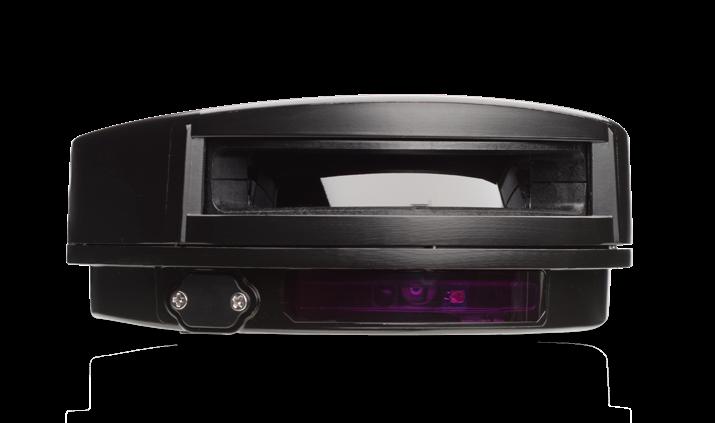
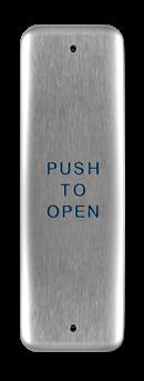
PRIMARY ACTIVATION
Push plate, touchless swirch, or radio controls
ADDITIONAL ACTIVATION
Utilize Virtual Push Buttons in addition to a knowing-act device
TECHNOLOGIES LASER Laser technology works according to the principle of Time-of-Flight. The sensor sends an intense light impulse in a defined direction and measures the time until the signal returns. As the speed of light is a constant value (approximately 300,000 km/s), this time is directly proportional to the distance between the sensor and the first object encountered by the light impulse.
As a result, and by sending multiple beams in multiple directions (2D or 3D), the sensor is capable of knowing the exact position of any object in its detection area at any given time.
ACTIVE INFRARED WITH BACKGROUND ANALYSIS Active infrared with background analysis technology works with a background (e.g. a sensor shines infrared light on the floor). In this case, the sensor lights up one or more areas and analyzes the energy that returns. Detection is triggered if there is any significant difference when compared to the original picture.
ACTIVE INFRARED WITH BACKGROUND SUPPRESSION Active infrared with background suppression technology works on the principle of “triangulation” in which the sensor calculates the distance between the emitter and receiver. The emission angle is already known and the reflection angle becomes the key element as the distance to the object can be calculated according to the position of the reflected spot on the receiver side (a triangle can be drawn when you know one distance and two angles).
PASSIVE INFRARED Passive infrared technology measures the infrared light radiating from objects in its field of view. Motion or presence is detected when an infrared source with one temperature, such as a human being, passes in front of an infrared source with another temperature, such as the normal environment.
RADAR Radar technology, also known as microwave technology, is based on the Doppler Effect: the radar sensor continuously emits microwaves with a certain frequency in a defined area. These microwaves are reflected back to the sensor by all of the objects present in its environment.
PIEZO Piezo technology, also known as piezoelectric, is the process of converting mechanical pressure (pushing a button) into electrical energy. A piezo switch is paired with a field effect transistor (FET) that, when pushed, allows current to flow through the FET.
RADIO CONTROL FREQUENCY Radio control frequency wireless technology uses transmitters and receivers operating on specific radio frequencies. The transmitter applies a radio frequency alternating current to an antenna, which then radiates radio waves. The receiver receives the transmitted frequency and converts the information into a usable form.
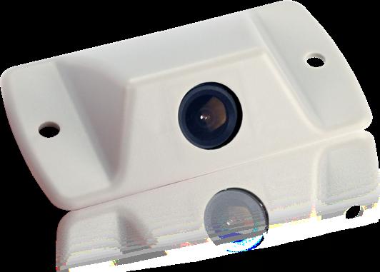
VIDEO Video technology uses optics and light to create pictures and videos. Enhanced definition cameras capture door environment and traffic usage in full color and high quality. Cameras are used within sensors to increase security and decrease liability.
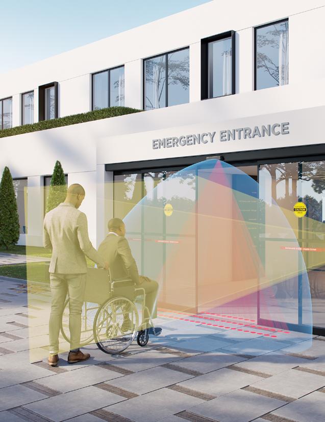
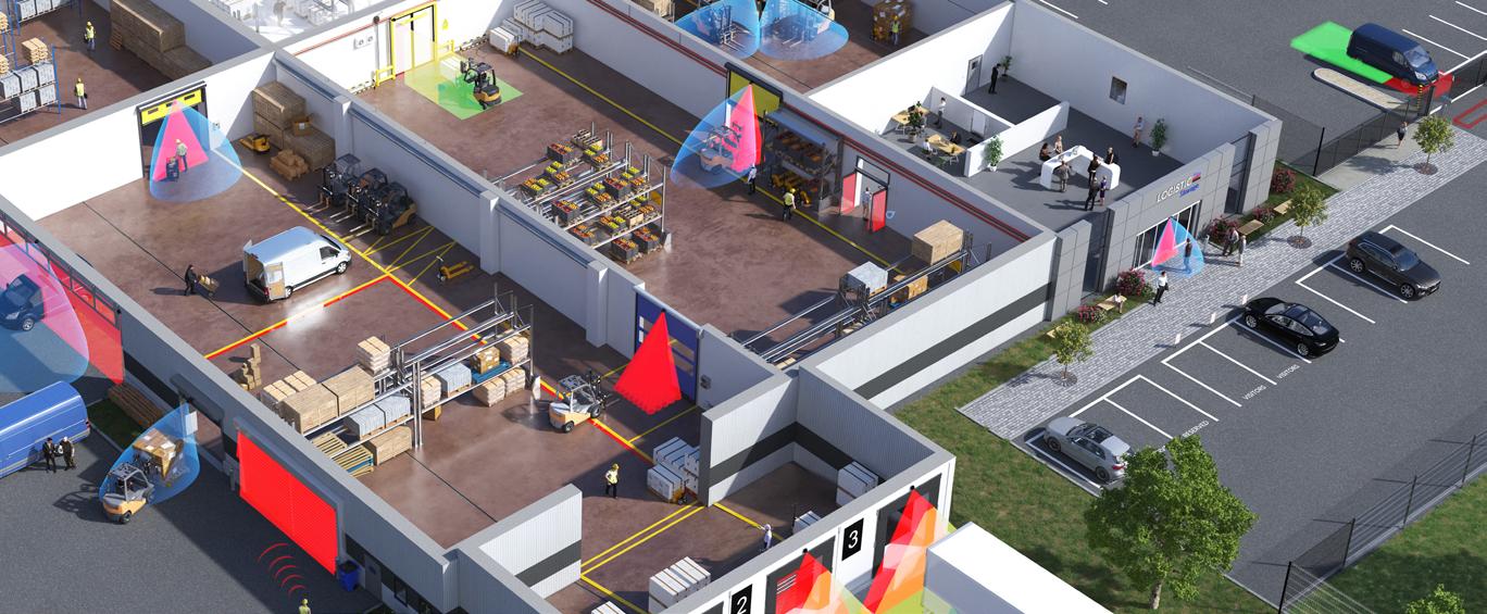
FIND YOUR APPLICATION PEDESTRIAN ENTRANCE SENSORS Pedestrian Entrance Sensors are designed to improve the flow of people moving in, out and through a building. These solutions maximize safety and accessibility in retail centers, airports, hospitals, educational facilities, offices and other areas with consistent pedestrian-based traffic. Security and Access Control solutions are designed to control access, provide security and streamline workflow in and around buildings. Sensing solutions found within this segment pair seamlessly with door controls and security systems to help maximize safety and security.
DOORS & WINDOWS LOW ENERGY DOORS
SLIDING DOORS
SECURITY & ACCESS CONTROL SWINGING DOORS
REVOLVING DOORS
AUTOMATED WINDOWS
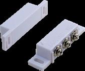
KNOWING ACT DEVICES
SPEED LANES AND TURNSTILES
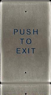
REQUESTTO-EXIT
ACCESS CONTROL
INDUSTRIAL DOOR & GATE SENSORS ESCALATORS
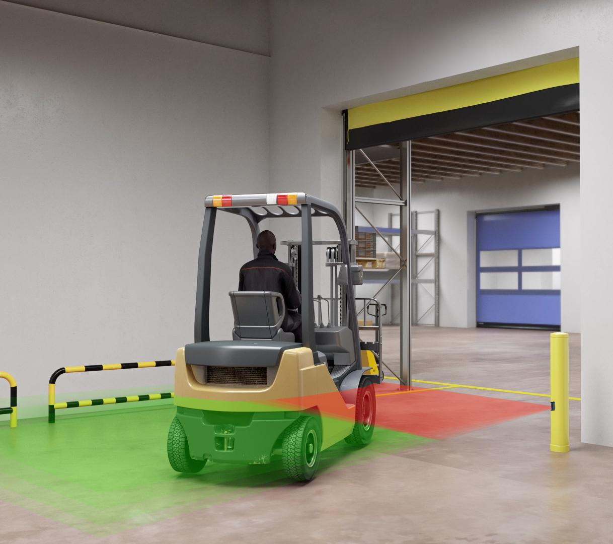
Industrial Door & Gate Sensors can be found in warehouses, distribution centers, delivery bays, docks and other areas needing to effectively manage industrial traffic. These solutions include sensors, signal lights and other devices dedicated to improving traffic flow and protecting resources. Common applications include sensors designed for the activation and safety of high performance doors.
DOORS HIGH PERFORMANCE DOORS COMMERCIAL DOORS LOADING DOCKS
GATES & BARRIERS BARRIERS GATES
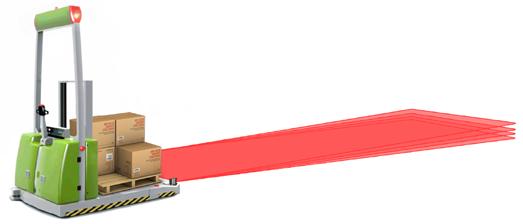
FACTORY & LOGISTICS AUTOMATION SOLUTIONS Factory and logistic automation solutions are dedicated to applications that ensures the safety and protection of people, equipment and mobile robots in the industrial environments, including factories, warehouses, etc.
AUTONOMOUS ROBOTS AUTOMATED GUIDED VEHICLES
AUTONOMOUS MOBILE ROBOTS
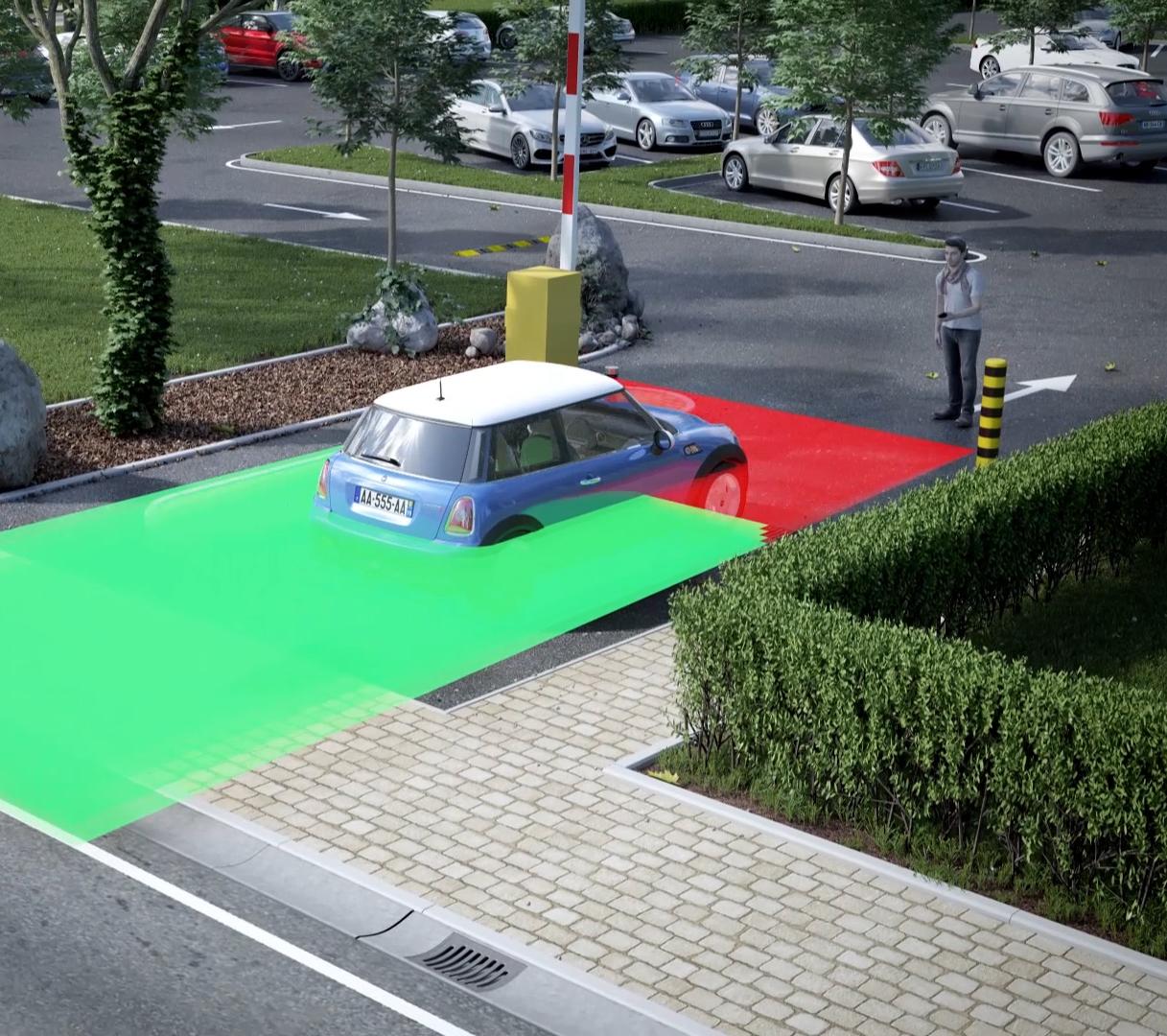
TRAFFIC & TRANSPORT SOLUTIONS PARKING SOLUTIONS
ASSET PROTECTION
TRAFFIC & TOLL GATES
AUTOMATIC FORKLIFT
ARTWORK PROTECTION
PERIMETER PROTECTION
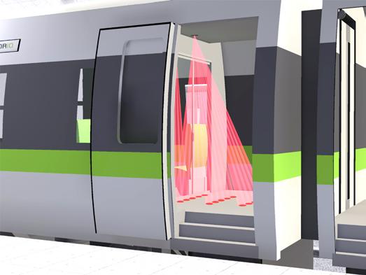
TRAIN, TRAM & SUBWAY DOORS BUS DOORS
SCREEN DOORS
WAREHOUSING
FIND YOUR SOLUTION INDICATORS COLIBRI ONE UNIDIRECTIONAL MOTION SENSOR FOR OFF-DOOR APPLICATIONS
Customizable Settings
Variable sensitivity adjustment provides different detection areas
Variable Mounting
Lateral angle adjustment for ceiling-, wall-, and low-level mount versatility
TECHNICAL SPECIFICATIONS Technology Microwave Doppler radar
Detection Mode Motion
Transmitter Frequency 24.150 GHz
Transmitter Radiated Power < 20 dBM EIRP
Transmitter Power Density < 5 mW / cm²
Min. Detection Speed 2 in/s (measured in sensor axis)
Supply Voltage
12 – 24 VDC 30% / -10%
Mains Frequency 50 – 60 Hz
Max. Power Consumption < 2 W
Output
Max. Contact Current Max. Contact Voltage
Solid-state-relay (free of potential change-over contact)
100 mA
35 VDC / 24 VAC
Mounting Height 6 – 10’
Degree of Protection IP54
Temperature Range -4 – 131 °F
Dimensions 3 1⁄5” (W) × 2 2⁄5” (H) × 2 1⁄5” (D)
Tilt Angles 0 – 90° vertical; -30 – 30° lateral
Materials ABS, PC
Weight 5 oz
Cable Length 8’
Norm Conformity R&TTE 1999 / 5 / EC
EMC 2004 / 108 / EC
Compact, Low Profile Compact size provides flexibility in mounting
Ideal For Off-Door Applications
Pairs with LED SIGNAL LIGHTS for warning indication applications
PRODUCT SERIES
10COLIBRI1 Motion sensor
EAGLE ARTEK COMPACT, MOTION SENSOR FOR AUTOMATIC DOORS Compact and Attractive Design Slim and compact design permits integration with all types of automatic door operators
Energy Efficient
Immunity Filter, Field Size, and Field Shape settings work together with direction sensing capability (Detection Mode) to reduce door open time
TECHNICAL SPECIFICATIONS Technology Microwave
Detection Mode Motion
Transmitter Frequency 24.15 GHz
Transmitter Radiated Power < 20 dBm EIRP
Transmitter Power Density < 5mW / cm²
Max. Detection Range wide: 13' × 6.5' narrow: 6.5' × 7' (@ 7' high)
Min. Detection Speed 2 in/s
Supply Voltage*
12 – 24 VAC ±10% (50 – 60 Hz) 12 – 24 VDC 30% / -10%
Max. Power Consumption < 1 W
Output*
Max. Switching Voltage
Max. Switching Current
Solid-state Relay (Free of Polarity)
30 VAC / 42 VDC 100mA (Resistive)
Mounting Height 6 – 13'
Tilt Angles 0 – 90° vertical -30 – 30° lateral
Temperature Range -4 – 131 °F (-20 – 55 °C)
Dimensions 4.72" (L) × 1.96" (H) × 1.96" (W)
Material ABS
Weight
120 g
Cable Length 8'
Degree of Protection
FCC Certification
IP54
FCC: G9B-100606
IC: 4680A-100606
Easy to Use Electronic management of the radar field shape and push-button adjustments allow for quick installation and setup
Easy to Retrofit Same mounting references and plug-in interface accessory make it easy to retrofit EAGLE
PRODUCT SERIES 10EAGLEARTEK Microwave motion sensor
10EARA Rain accessory
10EACA Ceiling accessory (white)
10EACA-BLK Ceiling accessory (black)
10EABA Bracket accessory
35.0303
Replacement cover (black)
35.0319 Replacement cover (white)
35.0320 Replacement cover (silver)
10EARETROFIT Retrofit interface
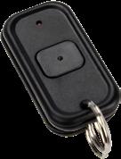
10REMOTE Universal remote control for sensor setup
FALCON FAMILY MOTION SENSOR FOR INDUSTRIAL DOORS, GATES, AND WARNING INDICATION
Energy Savings
Bidirectional + unidirectional approach and unidirectional depart microwave detection options
Remote Control Adjustments Remote control programming enables user to quickly and safely make changes from the ground
Rated For Harsh Environments
TECHNICAL SPECIFICATIONS Technology
Radiated Frequency
Transmitter Radiated Frequency
Radiated Power Density
PRODUCT SERIES Microwave Doppler radar
24.150 GHz
< 20 dBm EIRP
< 5 mW / cm²
Detection Mode Motion
Detection Zone
FALCON
FALCON XL
FALCON WIDE
13’ × 16’ at 16’
13’ × 6 1/2’ at 8 1⁄5’
30’ × 11’ at 21’ Typical at 30° and field size 9
Tilt Angles 0 – 180°
Output
Max. Contact Voltage
Max. Contact Current
Max. Switching Power Relay (free of potential change-over contact) 42 VAC/VDC 1 A (resistive) 30 W (DC); 60 VA (AC)
Minimum Detection Speed 2 in/s*
Mains Frequency 50 – 60 Hz
Supply Voltage 12 – 24 VAC; ±10% 12 – 24 VDC; 30% / -10%
Power Consumption < 2 W
Mounting Height
FALCON
FALCON XL
FALCON WIDE 11 1/2 – 23’ 6 1/2 – 11 1/2’ 11 1/2 – 21’
Dimensions 3 3/4“ (W) × 4“ (H) × 5“ (L)
Materials ABS, PC
Degree of Protection IP65
Norm Conformity
* Measured in optimal conditions
Temperature Range -22 – 140 ºF
EMC: 2004 / 108 / EC
R&TTE: 1999 / 5 / EC
10FALCON Industrial motion detector (11 1⁄2 – 23’ high mount)
10FALCONW Industrial motion detector with wide detection fields (11 1⁄2 – 21’ high mount)
10FALCONXL Industrial motion detector for low mounting (6 1⁄2 – 11 1⁄2’ high mount)
10INDBRACKET Industrial mounting bracket
10MINIBRACKET Short, adjustable mounting bracket
10WBA Universal mounting bracket arm
10WBAMOUNT Universal mounting bracket plate
10REMOTE Universal remote control for sensor setup
20.5365 FALCON harness (100’)
35.1568 FALCON harness (30’)
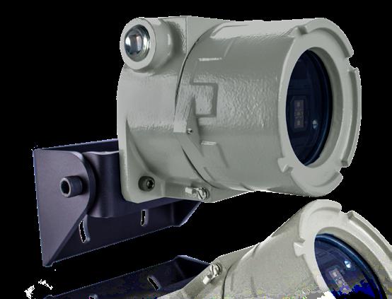
FALCON EX FAMILY MOTION SENSOR WITH EXPLOSION-PROOF AND FLAME-PROOF HOUSING
Energy Savings
Bidirectional + unidirectional approach and unidirectional depart microwave detection options
Adjustable Detection Settings
Six modes of detection filtering for pedestrian and parallel traffic rejection
Easy to Program
Remote control programming enables user to quickly and safely make changes from the ground
Explosion-proof and Highly Durable
Explosion-proof and flame-proof housing weighs 11 pounds
TECHNICAL SPECIFICATIONS
Technology
Radiated Frequency
Transmitter Radiated Frequency Radiated Power Density
Microwave Doppler radar
24.150 GHz < 20 dBm EIRP < 5 mW / cm²
Detection Mode Motion
Detection Zone
FALCON EX
FALCON EX XL
FALCON EX WIDE
13’ × 16’ at 16’ 13’ × 61/2’ at 81⁄5’ 30’ × 11’ at 21’ Typical at 30° and field size 9
Tilt Angles -90 – 30° in elevation
Output
Max. Contact Voltage
Max. Contact Current
Max. Switching Power Relay (free of potential change-over contact) 42 VAC/VDC 1 A (resistive)
30 W (DC); 60 VA (AC)
Minimum Detection Speed 2 in/s
Mains Frequency 50 – 60 Hz
Supply Voltage 12 – 24 VAC; ±10% 12 – 24 VDC; 30% / -10%
Maximum Power Consumption < 2 W
Mounting Height
FALCON EX
FALCON EX XL
FALCON EX WIDE 11 1/2 – 23’ 6 1/2 – 11 1/2’ 11 1/2 – 21’
Dimensions
Housing and Bracket 5 1/2” (L) × 7 1/2” (W) × 9” (H)
Electrical Access
NPT Pipe Thread 3/4”
Weight 10 lbs
Cable Length See User’s Guide for reference
Materials Copper-free Aluminum, Aluminum
Temperature Range -22 – 140 °F
Housing Certification* See User’s Guide
Norm Conformity
EMC: 2004 / 108 / EC
R&TTE: 1999 / 5 / EC
* Adalet / Scott Fetzer Co., UL Listing #E81696
PRODUCT SERIES 10FALCONEX100
Industrial motion detector with 100’ harness (11 1⁄2 – 23’ high mount)
10FALCONEXW100 Industrial motion detector with wide detection fields and 100’ harness (11 1⁄2 – 21’ high mount)
10FALCONEXXL100 Industrial motion detector for low mounting with 100’ harness (6 1⁄2 – 11 1⁄2’ high mount)
10INDBRACKET Industrial mounting bracket
10REMOTE Universal remote control for sensor setup
20.5365 FALCON harness (100’)
35.1568 FALCON harness (30’)
PHOENIX EXTM FAMILY MOTION SENSOR WITH EXPLOSION-PROOF AND FLAME-PROOF HOUSING FOR INTRUSION PROTECTION
Energy Savings
Bidirectional + unidirectional approach and unidirectional depart microwave detection options
Tamper Proof
Integrated, tamper alert switch and end-of-line resistors
TECHNICAL SPECIFICATIONS Technology
Transmitter Frequency
Transmitter Radiated Power
Transmitter Power Density
Microwave Doppler radar
24.150 GHz
< 20 dBm EIRP
< 5 mW / cm²
Detection Mode Motion
Output*
Maximum Contact Voltage
Maximum Contact Current
Maximum Switching Power
Anti-Tamper Feature
PHOENIX EX
PHOENIX EX-IT
Certified Housing Explosion-proof and flame-proof housing, weighs 10 pounds
Customizable Detection Angle Tilt adjustment angle: -90 to 30° in elevation
Relay (free of potential change-over contact)
42 VAC/VDC
1 A (resistive)
30 W (DC); 60 VA (AC)
1) product anti-tamper (magnetic switch within cover, alerts when cover is unscrewed)
2) application-based anti-tamper (tamper alert via end-of-line resistor)
Tamper alert via output
Minimum Detection Speed 2 in/s*
Supply Voltage 12 – 24 VAC; ±10% 12 – 24 VDC; 30% / -10%
Mains Frequency 50 – 60 Hz
Maximum Power Consumption < 2 W
Electrical Access 3/4”
Cable Length 30’ or 100’ (default), diameter 1⁄4" max
Detection Zone
PHOENIX EX
PHOENIX EX XL
PHOENIX EX WIDE
Mounting Height
PHOENIX EX
PHOENIX EX XL
PHOENIX EX WIDE
Dimensions
13’ × 16’ at 16’
13’ × 16 1/2’ at 8 1⁄5’
30’ × 11’ at 21’
Typical at 30° and field size 9
11 1/2 – 23’ 6 1/2 – 11 1/2’ 11 1/2 – 21’
Housing and Bracket 5 1/2” (H) × 7 1/2” (W) × 9” (L)
Weight 10 lbs
Temperature Range -22 – 140 °F
Housing Certification*** See User’s Guide
Norm Conformity EMC: 2004 / 108 / EC
R&TTE: 1999 / 5 / EC
PRODUCT SERIES 10PHOENIXEX100
10PHOENIXEXXL100
10PHOENIXEXW100
Industrial motion detector with 100’ harness (11 1⁄2 – 23’ high mount)
Industrial motion detector for low mounting with 100’ harness (6 1⁄2 – 11 1⁄2’ high mount)
Industrial motion detector with wide detection fields and 100’ harness (11 1 2 – 21’ high mount)
10PHOENIXEX-IT100 Industrial motion detector with 100’ harness (11 1⁄2 – 23’ high mount)
10PHOENIXEXXL-IT100 Industrial motion detector for low mounting with 100’ harness (6 1⁄2 – 11 1⁄2’ high mount)
10PHOENIXEXW-IT100 Industrial motion detector with wide detection fields and 100’ harness (11 1 2 – 21’ high mount)
10REMOTE Universal remote control for sensor setup
Contact your BEA Sales Representative for PHOENIX EXTM ordering information
* Measured in optimal conditions
** Output ratings may vary depending on optional end-of-line resistor values
*** Adalet / Scott Fetzer Co., UL Listing #E81696
SPARROW VARIABLE MOUNT, INDUSTRIAL MOTION SENSOR Flexible Mounting
Mounting height from 6 1⁄2 feet to 20 feet
Adjustable For Optimal Detection
Ten sensor-sensitivity settings can be applied to optimize detection
Weather Resistant IP64-rated enclosure for industrial and harsh environments
Customizable Settings
Immunity settings can be adjusted to reduce unwanted detections caused by rain, snow, and header vibrations
TECHNICAL SPECIFICATIONS
Technology
Transmitter Frequency
Transmitter Radiated Power
Transmitter Power Density
Microwave Doppler radar
24.150 GHz
< 20 dBm EIRP
< 5 mW / cm²
Detection Mode Motion
Tilt Angle
Output
Max. Contact Voltage
Max. Contact Current
Max. Switching Power
Minimum Detection Speed
Frequency
Supply Voltage
0 – 90° vertical; -120 – 120° lateral
Relay (free of potential change-over contact)
42 VAC – 60 VDC
1 A (resistive)
30 W (DC) / 60 VA (AC)
2 in/s (measured in the sensor axis)
50 – 60 Hz
12 – 24 VAC ±10%
12 – 24 VDC; 30% / -10%
Maximum Power Consumption < 2 W
Mounting Height 6 1/2 – 20’
Dimensions 5 1/2” (L) × 2 1/4” (H) × 2 1⁄5” (W)
Material ABS
Color Black
Weight 5.8 oz
Cable Length 30’
Temperature Range -22 – 140 °F
Degree of Protection IP64
Norm Conformity R&TTE 1999 / 5 / EC
EMC 2004 / 108 / EC
PRODUCT SERIES 10SPARROW Variable-mount motion sensor 10REMOTE Universal remote control for sensor setup 10INDBRACKET Industrial mounting bracket
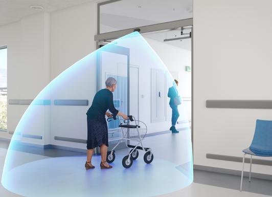
BODYGUARD-T OVERHEAD PRESENCE SENSOR FOR AUTOMATIC DOORS
Overhead Presence Sensor
Versatile sensor can be used on single swing, simultaneous pair, dual egress, and folding doors when coupled with an interface / lockout device
Tailor For Application Needs
Adjustable tilt angle from zero to 10°
Visible Indication
Visible LED indicates connection between sensor and door control
Customized Detection
Separate pattern width, depth, and sensitivity for open- and closeddoor states provide maximum flexibility
Standards Compliant
Fully monitored internally; capable of external monitoring
TECHNICAL SPECIFICATIONS Technology Active infrared
Detection Mode Presence
Installation Height (variable) 9’ 0” maximum (recommended: 6’ 6” – 8’ 0”)
Mounting Angles
BODYGUARD Only
With BODYMOUNT
Power Supply
5°, 10° (factory default setting: 5°) 0°, 5°, 10°
12 – 24 VAC/VDC ±10%
Frequency 50 – 60 Hz
Output
Max. Contact Voltage
Max. Contact Current
Max. Power Supply
60 VDC / 125 VAC 1 A 30 W (DC), 60 VA (AC)
Relay Hold Time 0.5 – 9 s
Operating Temperature -22 – 140 °F
Immunity Immune to electrical and radio frequency interference
Cable 4’
Weight 1 lb 11 oz
Dimensions 12” (W) × 2” (H) × 2” (D)
Materials Aluminum, ABS
Housing Black anodized aluminum
PRODUCT SERIES 10BODYGUARDT Header-mounted, safety sensor
10BODYMNT Spacer for BODYGUARD-T
10BGQD Quick-disconnect cable for BODYGUARD-T (78”)
10CAPKIT (1) left / (1) right end cap and mounting screws
10HORTONSSHARN BODYGUARD-T / SUPERSCAN-T relay harness for use with Horton Control
10LO21 Lock-out modules see page 55 for more information
10REMOTE Universal remote control for sensor setup
10URC Universal rain cover for BODYGUARD-T
15.0075 Harness for LO21 and LO21P
20.2015 BODYGUARD-T light pipe and cover for light pipe
30.0345 7-position, female pin connector
41.3879 Adjustable mounting clips for PCB
70.0207 BODYGUARD-T lens cut to 4 7⁄8”
FLY KIT COMPACT, PASSIVE INFRARED REQUEST-TO-EXIT SENSOR
Precise Infrared Detection
Sensing field adjustment masks provide accurate detection zones (two included)
Customizable
DIP switches for user-defined settings
TECHNICAL SPECIFICATIONS
Technology Passive infrared with microprocessor
Mounting Height
Recommended 6 1/2 – 8’ (max. 10')
Mounting Angles
Power Supply
0 – 180°
12 – 24 VAC ±10% 50/60 Hz
12 – 24 VDC -10% / 30%
Current Consumption < 10 mA (20 mA if the relay output is activated)
Contact Rating 1 A / 75 VDC or 50 VAC potential free contact NO / NC
Optical Characteristics
Passive infrared with four elements 15 Fresnel lenses with full independent masking possibilities
Warm-up Time 10 s
Response Time 200 ms (max)
Relay Hold Time
Standard Fly
Fly Extended Relay Time
0.5 or 2 s 15 or 30 s
Operating Temperature -22 – 140 °F (-30 – 55 °C)
Cable 9’ 4-conductor cable with 5-pin connector
Weight 1.4 oz (40 g)
Sensor Dimensions 4” (W) × 1 4⁄5” (H) × 1” (D)
Housing Color Black
Adjustable Access Settings
Extended Relay Time (ERT) version is available for hold times of 15 or 30 seconds
Low-Profile Design
Compact, aesthetically pleasing design; packages include both ceiling- and surface-mount adapters
PRODUCT SERIES 10FLYKITB (1) Passive infrared detector for request-to-exit applications (black)
(1) Surface adapter (black)
(1) Flush mounted ceiling adapter (black)
10FLYKITBERT (1) Passive infrared detector with extended relay time (black)
(1) Surface adapter (black)
(1) Flush mounted ceiling adapter (black)
70.0011 22 gauge 4-conductor cable sold by the foot
FOCUS FAMILY FOCUSED, ACTIVE INFRARED PRESENCE SENSORS
Low-Profile Detection
Low profile, recessed mount enables FOCUS 2 and SMART FOCUS to protect pedestrians from contact with the moving door
Monitoring Capable SMART FOCUS is fully monitored (not FOCUS or FOCUS 2)
TECHNICAL SPECIFICATIONS 10FOCUS and 10FOCUS2
Technology Focused, active infrared
Detection Mode Presence
Power Supply 24 VAC/VDC ±10%
Current Consumption 60 mA (on); 30 mA (off)
Output Interface; Relay Relay; max. contact rating is 1 A at 30 V (resistive)
Detection Range 0 – 8 1⁄5’
Distance Adjustment 2 – 8’, rotating cam with linear adjustment
Detection Time < 50ms
Detection Signal Duration Infinite presence detection
LED Activity
Green No detection
Operating Temperature Range -30 – 140 °F
Connection to controller 5-conductor cable
Relay Output NO or NC
PRODUCT SERIES 10FOCUS Distance-measuring, active infrared presence sensor (surface-mount)
10FOCUS2 Distance-measuring, active infrared presence sensor (recessed-mount)
10SMARTFOCUS Distance-measuring, active infrared presence sensor (recessed-mount); adapts to environment by the push of a button
10SMARTFOCUSSMA Surface-mount adapter for SMART FOCUS sensor
15.0118 FOCUS 2 harness (240”)
70.0068 FOCUS harness (48”)
35.1128 6-conductor cable with socket for SMART FOCUS
70.0138 Lens extrusion, ordered by inch (9” needed for 10FOCUS lens replacement)
Perfect For Activation Of Small Windows and Pass-Thru
Horizontal mount for use in gate and barrier applications
10SMARTFOCUS
Technology Focused, active infrared
Detection Mode Presence detection by distance measurement
Detection Field 1 19 50” × 2 19⁄25” at 7 1/4’ mounting height
Light Indicator Red Orange ON during detection Flashes 1x after power on
Response Time 64 ms
Mounting Height 2 – 10’
Supply Voltage 12 – 24 VAC/VDC -5% / 10%
Mains Frequency 50 – 60 Hz
Max. Current Consumption 120 mA at 24 VAC / 80 mA at 24 VDC
Standard Output
Max. Contact Voltage
Max. Contact Current Max. Switching Power Relay (free of potential contact)
42 VAC/VDC
1 A (resistive)
30 W (DC) / 60 VA (AC)
Monitoring Input
Max. Contact Voltage Voltage Threshold 1 optocoupler (free of potential contact)
30 V High state: > 10 V Low State: < 1 V
Hold Time 0.5 s
Reflectivity min. 10% at IR-wavelength of 850 nm
Temperature Range -13 – 131 °F (-25 – 55 °C) 0 – 95% rel. humidity, non-condensing
Degree of Protection IP53
Dimensions
5 3⁄4” (L) × 1 3⁄5” (H) × 2” (D)
Length of Main Cable 8’
Norm Conformity
IEC 61000-6-2; IEC 61000-6-3
ISO 13849-1 Performance Level «c» CAT. 2 (under the condition that the door control system monitors the sensor at least once per door cycle)
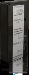
IS40P PRESENCE SENSOR WITH VIRTUAL LOOP FUNCTIONALITY Adjustable Learn Time
Nine unique infrared patterns capable of highly flexible presence detection in any industrial environment
Reduce False Detections
Six modes of detection filtering are available for microwave immunity, as well as pedestrian and parallel traffic rejection
TECHNICAL SPECIFICATIONS Technology Active infrared
Detection Mode Presence
Mains Frequency 50 – 60 Hz
Power Consumption < 3.5 W
Output
Max. Contact Voltage
Max. Contact Current
Max. Switching Power
Supply Voltage
2 relays (free of potential change-over contact)
42 VAC/VDC
1 A (resistive)
30 W (DC) / 48 VA (AC)
12 – 24 VAC; ±10%
12 – 24 VDC; 10% / -3%
Temperature Range -22 – 140 °F
Tilt Angle 15 – 45°
Transmitter Frequency / Wavelength 875 nm
Transmitter Power Density < 250 mW / m²
Detection Field 10’ × 10’ at max. mounting height of 16’ (emitting spots)*
Output Hold Time 0.5 s
Min. Detection Speed 0 in/s to activate detection
Reaction Time 250 ms
Mounting Height 8 – 16’
Humidity 0 – 95% non-condensing
Weight 14 oz
Dimensions 3 4⁄5“ (W) × 4” (H) × 5” (D)
Materials ABS, PC
Cable Length 32’
Degree of Protection IP65
Norm Conformity EMC: 2004 / 108 / EC
R&TTE: 1999 / 5 / EC
* Zone detected by SPOTFINDER (i.e. slightly larger than actual detection field)
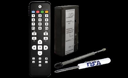
Programmable Via Remote
Remote control programming enables user to quickly and safely make changes from the ground (sold separately)
Easy to Program
Adjustable infrared immunity modes mitigate environmental disturbances such as subtle door vibrations, light, sun, rain, and snow
PRODUCT SERIES 10IS40P
10INDBRACKET
Industrial sensor utilizing active infrared presence detection
Industrial mounting bracket
10MINIBRACKET Short, adjustable mounting bracket
10WBA
10WBAMOUNT
Universal mounting bracket arm
Universal mounting bracket plate
10REMOTE Universal remote control for sensor setup
10SPOTFINDER Active infrared spotfinder
35.1566 8-pin conductor cable (30’)
IXIO-ST PRESENCE SENSOR FOR AUTOMATIC, SLIDING DOORS
Precise Presence Detection
Two 24-spot, high-density infrared, safety curtains providing precise presence detection
Easily Adjustable
Four visible, red, alignment spots are projected on the ground to assist in precise IR curtain adjustment
Ease of Setup
Intelligent programming and troubleshooting via a menu-driven LCD
Intelligent Solution
On-board microprocessor optimizes data analysis, monitors sensor performance, and enables system integration
Standards Compliant
Fully monitored internally, capable of external monitoring
TECHNICAL SPECIFICATIONS Detection Mode Presence
typical response time: < 200 ms (max: 500 ms)
Technology Active infrared with background analysis
Spot: 2” × 2” (typ)
Number of spots: max. 24 per curtain
Number of curtains: 2
Mounting Height 6 1/2 – 11 1/2’
local regulations may impact acceptable mounting height (pedestrian applications only)
Sensor Temperature
Range -13 – 131 °F 0 – 95% relative humidity, non-condensing
LCD screen is operational from 14 – 131 °F. The sensor may still be programmed in colder temperatures, but with the remote control.
PRODUCT SERIES 10IXIOST
Active infrared presence sensor for sliding doors
10ICA IXIO ceiling accessory
10IMB IXIO bracket accessory
10URA Universal rain accessory
10CDA IXIO curved door accessory
10IXIOSPACER IXIO spacer (black)
35.1286 IXIO replacement cover (black)
35.1302 IXIO replacement cover (white)
35.1303 IXIO replacement cover (silver)
10RETROFITSPACER Retrofit Spacer Kit (spacer, 2 1⁄2" harness, 9" harness)
20.5349 IXIO / ULTIMO control harness (10')
20.5359 Wire harness (30’)
10MINIBRACKET Short, adjustable mounting bracket
Output
Relay 1
2
Electromechanical relay (potential and polarity free)
Max. contact current: 1 A
Max. contact voltage: 30 VAC
Adjustable hold time: 0.5 – 9 s
Solid-state relay (potential and polarity free)
Max. contact current: 100 mA
Max. contact voltage: 42 VDC / 30 VAC
Test / Monitoring Input Sensitivity:
Low: < 1 V
High: > 10 V (max. 30 V)
Response time on test request: typical < 5 ms
Supply Voltage 12 – 24 VAC ±10%; 12 – 30 VDC ±10% (to be operated from SELV compatible power supplies only)
Power Consumption < 2.5 W
Noise < 70 dB
Compliance ISO 13849 PL «c» CAT. 2 (under the condition that the door control system monitors the sensor at least once per door cycle)
10REMOTE Universal remote control for sensor setup
Relay
IXIO-ST INDUSTRIAL PRESENCE SENSOR FOR SMALL, INTERIOR, INDUSTRIAL DOORS Precise Presence Detection
Two 24-spot, high-density infrared, safety curtains providing precise presence detection
Easily Adjustable
Four visible, red, alignment spots are projected on the ground to assist in precise IR curtain adjustment
Ease of Setup
Intelligent programming and troubleshooting via a menu-driven LCD
TECHNICAL SPECIFICATIONS
Detection Mode Presence
typical response time: < 200 ms (max: 500 ms)
Technology Active infrared with background analysis
Spot: 2” × 2” (typ)
Number of spots: max. 24 per curtain
Number of curtains: 2
Mounting Height 6'6" – 11'6"
local regulations may impact acceptable mounting height (pedestrian applications only)
Sensor Temperature
Range* -13 – 131 °F 0 – 95% relative humidity, non-condensing
LCD screen is operational from 14 – 131 °F. The sensor may still be programmed in colder temperatures, but with the remote control.
Intelligent Solution
On-board microprocessor optimizes data analysis, monitors sensor performance, and enables system integration
Standards Compliant
Fully monitored internally, capable of external monitoring
Output
Relay 1
Relay 2
Electromechanical relay (potential and polarity free)
Max. contact current: 1 A
Max. contact voltage: 30 VAC
Adjustable hold time: 0.5 – 9 s
Solid-state relay (potential and polarity free)
Max. contact current: 100 mA
Max. contact voltage: 42 VDC / 30 VAC
Test / Monitoring Input Sensitivity:
Low: < 1 V
High: > 10 V (max. 30 V)
Response time on test request: typical < 5 ms
Supply Voltage 12 – 24 VAC ±10%; 12 – 30 VDC ±10% (to be operated from SELV compatible power supplies only)
Power Consumption < 2.5 W
Noise < 70 dB
Degree of Protection IP54
Compliance ISO 13849 PL «c» CAT. 2 (under the condition that the door control system monitors the sensor at least once per door cycle)
PRODUCT SERIES 10IXIOSTINDUS Active infrared presence sensor for sliding doors
10ICA IXIO ceiling accessory
10IMB IXIO bracket accessory
10URA Universal rain accessory
10CDA IXIO curved door accessory
10IXIOSPACER IXIO spacer (black)
35.1286 IXIO replacement cover (black)
35.1302 IXIO replacement cover (white)
35.1303 IXIO replacement cover (silver)
10RETROFITSPACER Retrofit Spacer Kit (spacer, 2 1 2" harness, 9" harness)
20.5349 IXIO / ULTIMO control harness (10')
20.5359 Wire harness (30’)
10MINIBRACKET Short, adjustable mounting bracket
10REMOTE Universal remote control for sensor setup
LZR®-FLATSCAN U950/U952 COMPACT, SINGLE CURTAIN, LASER SCANNER FOR RAW DATA APPLICATIONS
Background Independent
Background or substrate has limited effect on measurements
LASER-Based Measurements
Measurement range is up to 8 meters (26 feet)
TECHNICAL SPECIFICATIONS Technology
LASER scanner, time-of-flight measurement
Measurement range max. 26’3” (8 m)
13’ (4m) @ 2% remission factor
26’3” (8m) @ 8% remission factor
Number of planes 1
Number of points/plane* max. 400 pts
Angular resolution* min. 0.18°
Angular coverage* max. 108°
Response time measurements are refreshed every:
10.75 ms @ angular resolution ≥ 0.74°
43 ms @ angular resolution < 0.74°
Scanning rate
93 scans/sec. @ angular resolution ≥ 0.74°
23.25 scans/sec. @ angular resolution < 0.74°
Emission characteristics IR LASER: Wavelength 905 nm; max. output pulse power 25 W; Class 1
Measurement error
± 1 3/16” @ 13’ (±30mm @ 4m) ± 2 3/4” @ 26’3” (±70mm @ 8m)
Repeatability ± 3/16” @ 13’ (±5mm @ 4m) ± 25/64” @ 26’3” (±10mm @ 8m)
Serial communication
Type
Interface
Communication mode
Transmission speed
Topology
Symbol coding
Type
File type
Byte order see LZR®-FLATSCAN U Protocol (available for download on our website) asynchronous RS 485 full-duplex max. 921,600 bit/sec (configurable) point to point
1 start bit, 1 stop bit, no parity bit 8 bits little endian, LSB first 1 tri-colored LED: sensor/communication status
Supply voltage 12 – 24 VDC ±15%
Power consumption < 2 W
Peak current at power-on
0.8 A (max. 20 ms @ 24 V)
Cable length 8’2-1/2” (2.5m)
Connector DF11-6DS-2C
Uni-Directional or Bi-Directional Standard RS485 bus communication (bi-directional)
Superior Object Recognition
No external illumination of target object necessary as compared to camera systems
Dimensions (U950 only) 5 1⁄2” (L) × 3 1⁄3” (H) × 1” (D) [142mm (L) × 85mm (H) × 23mm (D)] mounting bracket + 1⁄4” (7mm)
Material - Color (U950 only) PC/ASA - Black
Tilt angles (U950 only) -2 – 6° (with mounting base) 2 – 10° (without mounting base)
Protection degree (U950 only) IP54 [IEC 60529]
Temperature range powered: -22 – 140 °F (-30 – 60 °C) unpowered: 14 – 140 °F (-10 – 60 °C)
Humidity 0 – 95% non-condensing
Vibrations < 2 G
Compliance 2014/30/EU; 2011/65/EU; IEC/EN 60825-1 Laser safety; IEC/EN 61000-6-2; IEC/EN 61000-6-3 EMC
* These parameters can be configured via the RS 485 communication interface. For more information on the existing options, see LZR®-FLATSCAN U Protocol.
PRODUCT SERIES 10LZRFLATSCANU950LB LASER scanner for raw data applications (left)
10LZRFLATSCANU950RB LASER scanner for raw data applications (right)
10LZRFLATSCANU952 LASER scanner without housing for raw data applications
LZR®-FLATSCAN A COMPACT, LASER SCANNER FOR FACTORY & LOGISTICS APPLICATIONS
Versatile Sensor Orientation
Left or right, horizontal or vertical sensor mounting allows for convenient sensor installation based on application needs
Robust Construction
Metal enclosure and IP66 rating protects sensor in harsh environments
TECHNICAL SPECIFICATIONS Technology
LASER sensor, Time-of-Flight measurement
Detection Mode Presence
Max. Detection Range max. 18' × 18' (13’ 1 ⁄ 8' @ 5% reflectivity)
Opening Angle 90°
Tilt Angles
±3° (with bracket)
Emission Characteristics wavelength 905nm; max. output pulse power 25W (CLASS 1) wavelength 635nm; max. output CW power
Angular Resolution
0.95mW (CLASS 2) visible spot
0.23° (400 spots within 90°)
LEDs 1 tri-colored LED: detection / output status
Supply Voltage* 12 – 24 VDC ±15%
Power Consumption ≤ 2. W, peak current: 1A
Response Time max. 50ms (+ output activation delay)
Output
Max. Switching Voltage
Max. Switching Current
Max. Contact Voltage
Max. Contact Current
Max. Switching Power 1 opto (galvanic isolation - polarity free)
Dimensions
42 VAC/VDC 100mA 1 relay (free of potential contact)
42 VAC/VDC 1A (resistive)
30W DC / 60 VAC
5” (L) × 3 1⁄2” (H) x 2” (D) (without bracket)
Color Black
Protection Degree IP66 (IEC 60529)
Temperature Range (when powered) -22 – 140 °F (-30 – 60 °C)
Humidity 0 – 95% non-condensing
Vibrations < 2 G
Compliance
IEC 60825-1, IEC 60950-1, IEC 61000-6-2, IEC 6100063, IEC 60529:2001
* If only VAC power is available, a 12V transformer paired with a rectifier must be used. Do not use a 24V transformer and rectifier as this will cause damage to the product.
Compact Design
Low-profile solution (3.5 inch height) reduces risk of wear and tear in vehicle applications
PRODUCT SERIES 10LZRFLATSCAN-A
10FSSMB*
LZR-FLATSCAN A sensor
LZR-FLATSCAN S/A bracket
10REMOTE** BEA Universal Remote Control
10PSMDR2024 DIN rail power supply, 100 – 240 VAC / 24 VDC
10PSST242 Plug-in power supply
* Required for installation (sold separately)
** Required for installation and adjustment (sold separately)
LZR®-FLATSCAN S COMPACT, SINGLE-CURTAIN, LASER SCANNER FOR DOOR, GATE, AND BARRIER APPLICATIONS
Inductive Loop Alternative
Virtual presence loop ideal for applications where cutting ground for loops is prohibited, impossible, or expensive
Versatile Sensor Orientation
Left or right, horizontal or vertical sensor mounting allows for convenient sensor installation based on application needs
Robust Construction
Metal enclosure and IP66 rating protects sensor in harsh environments
TECHNICAL SPECIFICATIONS
Technology
LASER sensor, Time-of-Flight measurement
Detection Mode Presence
Max. Detection Range max. 18' × 18' (13’ 1 ⁄ 8' @ 5% reflectivity)
Opening Angle 90°
Tilt Angles
±3° (with bracket)
Emission Characteristics wavelength 905nm; max. output pulse power 25W (CLASS 1) wavelength 635nm; max. output CW power
0.95mW (CLASS 2) visible spot
Angular Resolution 0.23° (400 spots within 90°)
LEDs 1 tri-colored LED: detection / output status
Supply Voltage* 12 – 24 VDC ±15%
Power Consumption ≤ 2. W, peak current: 1A
Response Time max. 50ms (+ output activation delay)
Output
Max. Switching Voltage
Max. Switching Current
Max. Contact Voltage
Max. Contact Current
Max. Switching Power 1 opto (galvanic isolation - polarity free)
42 VAC/VDC 100mA
1 relay (free of potential contact)
42 VAC/VDC 1A (resistive)
30W DC / 60 VAC
Dimensions 5” (L) × 3 1⁄2” (H) x 2” (D) (without bracket)
Color Black
Protection Degree
IP66 (IEC 60529)
Temperature Range (when powered) -22 – 140 °F (-30 – 60 °C)
Humidity 0 – 95% non-condensing
Vibrations < 2 G
Compliance IEC 60825-1, IEC 60950-1, IEC 61000-6-2, IEC 6100063, IEC 60529:2001
* If only VAC power is available, a 12V transformer paired with a rectifier must be used. Do not use a 24V transformer and rectifier as this will cause damage to the product.
Compact Design
Low-profile solution reduces risk of wear and tear in vehicle applications
Reduce Unwanted Detections
Fog filter and additional immunity settings allow for field adjustments to mitigate environmental interferences
PRODUCT SERIES 10LZRFLATSCAN-S LZR-FLATSCAN S sensor
10FSSMB* LZR-FLATSCAN S/A bracket
10REMOTE** BEA Universal Remote Control
10PSMDR2024 DIN rail power supply, 100 – 240 VAC / 24 VDC
10PSST242 Plug-in power supply
* Required for installation (sold separately)
** Required for installation and adjustment (sold separately)
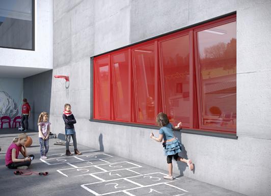
LZR®-FLATSCAN W SAFETY SENSOR FOR AUTOMATED WINDOWS Full Coverage of the Window
Pattern covers the entire window – including the inner frame borders – up to 13 feet
Easy and Flexible Mounting
Universal mounting base offers flexible installation and allows a variety of positions to suit niche application needs
TECHNICAL SPECIFICATIONS Technology LASER scanner, Time-of-Flight measurement, Background analysis
Detection Mode Presence
Max. Detection Range 13’ (diagonal) (e.g. @ 40' width, max. 16’)
Number of Curtains 1
Measurement Points 400
Angular Resolution
0.27°
Min. Object Size 3/4” (depending on the settings and the installation)
Optical Characteristics IR LASER, Class 1 wavelength: 905 nm output power: < 0.1mW
Supply Voltage 12 – 24 VDC ±15%
The equipment must be powered by a SELV limited power source ensuring double insulation between primary voltages and the Equipment supply.
The supply current should be limited to 1.5A.
Power Consumption ≤ 2 W
Typ. Response Time 400 ms
Peak Current at Power-on 0.8A (max. 20 ms @ 24 VDC)
Output
Max. Switching Voltage
Max. Switching Current 2 solid state relays (galvanic isolation - polarity free) 42 VAC/VDC 100 mA
Input
Max. Contact Voltage
Voltage Threshold
1 optocoupler (galvanic isolated - polarity free)
30 V DC (over-voltage protected)
Log. H: >8 VDC
Log. L: <3 VDC
LED Signals 1 tri-colored LED: detection/output status
Dimensions 5 3⁄5” (L) × 3 11⁄32” (H) × 1 1⁄3” (D) (mounting base adds 1⁄2”)
Materials / Color PC, ASA / black
Tilt Angles
Protection Degree
-2 – 6° (with mounting bracket)
2 – 10° (without mounting bracket)
IP54
Temperature Range -22 – 140 °F if powered
14 – 140 °F without power
Quick and Intuitive Configuration
The detection field size is defined by a simple hand movement; height and width of the field are automatically calculated
Virtual Push Button
One or both virtual push buttons can be programmed to activate the opening or closing of the window
Humidity 0 – 95% non-condensing
Vibrations < 2 G
Compliance
PRODUCT SERIES IEC 60335-2-103
ISO 13849-1 (PL “d”); IEC 61508 (SIL2)
10LZRFLATSCAN-WLB Safety sensor for automated windows (left)
10LZRFLATSCAN-WRB Safety sensor for automated windows (right)
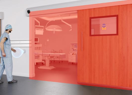
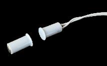
LZR®-FLATSCAN SW SINGLE CURTAIN, STAND ALONE, DOOR MOUNTED, SAFETY SYSTEM FOR FULL- AND LOW-ENERGY SWING DOORS
Background Independence
LASER technology ensures independence of all types of flooring (pedi-mats, carpet, reflective flooring, wet surfaces, etc.) and the surrounding environment of the door (guide rails, walls, weather, etc.)
Leading Edge Safety
Leading-edge safety extends the detection area beyond the leading edge of the door for enhanced safety
Hand Gesture Setup™
Easy door-width programming using Hand-Gesture Setup™ reduces configuration time
Reduced Components
Hub-less system offers fewer components for easier setup and installation
Reduced Uncovered Zone
LASER technology provides a reduced uncovered zone of down to 3⁄4 inch
UL10B/C Listed Fire rated for up to one hour
TECHNICAL SPECIFICATIONS Technology LASER scanner, Time-of-Flight measurement
Detection Mode Presence
Max. Detection Range 13’ (diagonal) with reflectivity of 2% (e.g. at (W) × 5’ > max. (H) × 12’) see Page 15 of Users Guide
Detection Area
Door Leaf Safety
Pinch Zone Safety 90° 16°
Angular Resolution
Door Leaf Safety
Materials / Color PC / ASA / Black, White, or Silver
Tilt Angles
2 – 10° (without mounting bracket)
Degree of Protection IP54 (EN 60529)
Temperature Range -22 – 140 °F (if powered)
Humidity 0 – 95% non-condensing
Vibrations < 2 G
Min. Door Leaf Speed 2° / s
Norm Conformity
Pinch Zone Safety 1.3°
Typ. Min. Object Size
Door Leaf Safety
Pinch Zone Safety
Emission Characteristics
0.2°
4” at 13’ (in proportion to object distance, DIP 2 = ON)
3/4” at 13’ (in proportion to object distance, DIP 2 = ON)
IR LASER Wavelength 905 nm; max. output pulse power 25 W; Class 1
Supply Voltage 12 – 24 VDC ±15% *
Power Consumption ≤ 2 W
Response Time
Door Leaf Safety
Pinch Zone Safety max. 50 ms max. 90 ms
Test Input 30 VDC (max. switching voltage) low < 1 V high > 10 V (voltage threshold)
Output
Max. Switching Voltage
Max. Switching Current
LED Activity
Red Green
Yellow
Dimensions
2 electronic relays (galvanic isolation - polarity free)
42 VAC/VDC 100 mA
Swing-side detection
Approach-side detection
Error
5 1⁄2” (W) × 3 1⁄ 3” (H) x 1” (D) (mounting bracket adds 1⁄4”)
ISO 13849-1 Pl “d”/ CAT2; IEC 60825-1; IEC 60950-1; IEC 61000-6-2; IEC 61000-6-3; IEC 62061 SIL 2; UL 10B/C Fire-Rated 1 hour (file #R39071) - black material only
* This sensor is powered by DC voltage only. If only VAC power is available, a 12V transformer paired with a rectifier must be used. Do not use a 24V transformer and rectifier as this will cause damage to the product.
LZR®-FLATSCAN SW SINGLE CURTAIN, STAND-ALONE, DOOR MOUNTED, SAFETY SYSTEM FOR FULL- AND LOW-ENERGY SWING DOORS
PRODUCT SERIES 10LZRFLATSCAN-SWB Full-energy, swing door, safety system (black)
10LZRFLATSCAN-SWS Full-energy, swing door, safety system (silver)
10LZRFLATSCAN-SWW Full-energy, swing door, safety system (white)
10LZRFLATSCAN-LELB Low-energy, swing door, safety system (left mount, black)
10LZRFLATSCAN-LELS Low-energy, swing door, safety system (left mount, silver)
10LZRFLATSCAN-LELW Low-energy, swing door, safety system (left mount, white)
10LZRFLATSCAN-LERB Low-energy, swing door, safety system (right mount, black)
10LZRFLATSCAN-LERS Low-energy, swing door, safety system (right mount, silver)
10LZRFLATSCAN-LERW Low-energy, swing door, safety system (right mount, white)
10LZRFLATSCAN-LB LZR-FLATSCAN SW sensor (left, black)
10LZRFLATSCAN-LS LZR-FLATSCAN SW sensor (left, silver)
10LZRFLATSCAN-LW LZR-FLATSCAN SW sensor (left, white)
10LZRFLATSCAN-RB LZR-FLATSCAN SW sensor (right, black)
10LZRFLATSCAN-RS LZR-FLATSCAN SW sensor (right, silver)
10LZRFLATSCAN-RW LZR-FLATSCAN SW sensor (right, white)
10LZRFLATSCANGDA LZR-FLATSCAN glass door accessory
20.5433
35.0213
35.0214
35.0220
35.0221
35.0242
35.0243
35.1329
LZR-FLATSCAN control harness
LZR-FLATSCAN SW replacement cover (left, black)
LZR-FLATSCAN SW replacement cover (right, black)
LZR-FLATSCAN SW replacement cover (left, white)
LZR-FLATSCAN SW replacement cover (right, white)
LZR-FLATSCAN SW replacement cover (left, silver)
LZR-FLATSCAN SW replacement cover (right, silver)
LZR-FLATSCAN primary/secondary harness
70.5745 Sentrex retrofit accessory
70.5751
70.5752
70.5753
LZR-FLATSCAN spacer (silver)
LZR-FLATSCAN spacer (white)
LZR-FLATSCAN spacer (black)
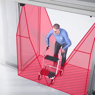
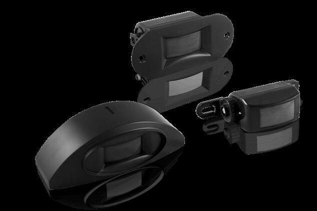
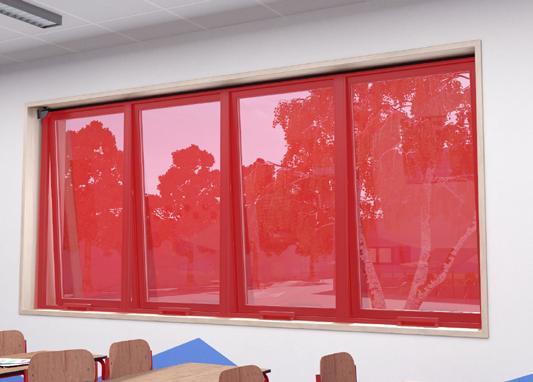
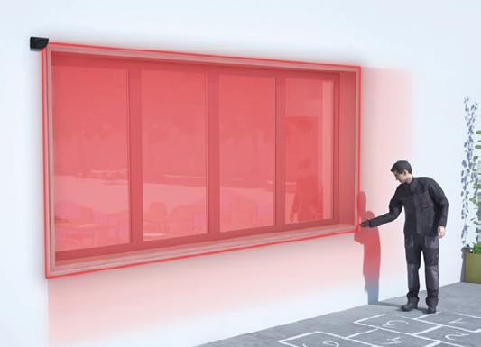
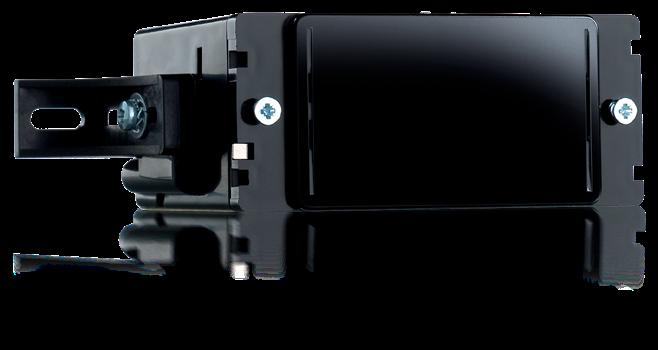
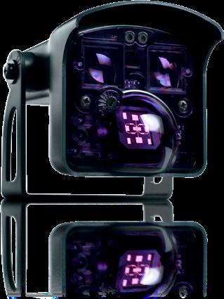
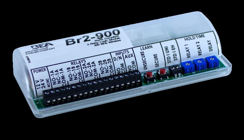
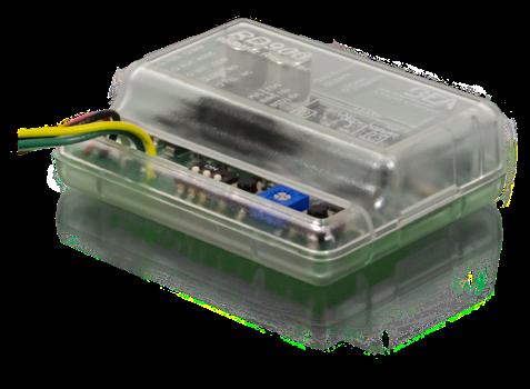
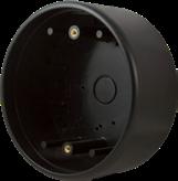
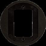
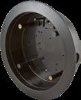
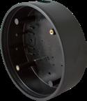
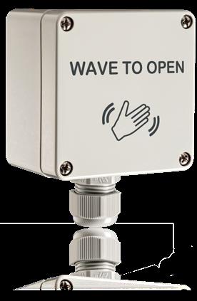
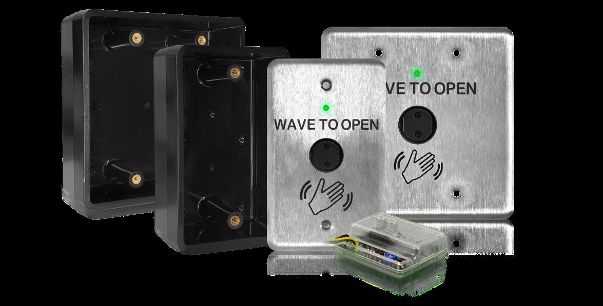
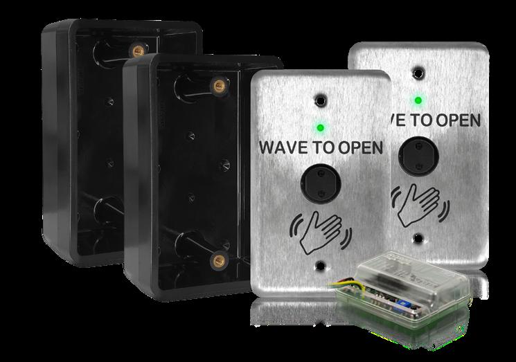
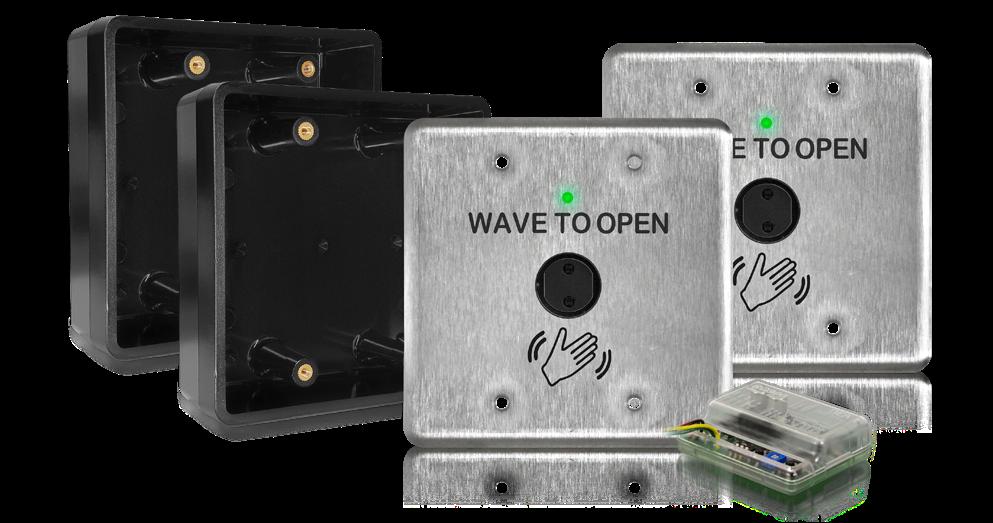
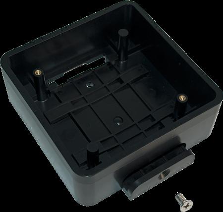
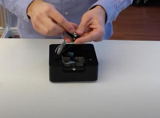
LZR®-FLATSCAN 3D SW FOUR CURTAIN, STAND ALONE, DOOR MOUNTED, SAFETY
SENSOR Advanced Safety
The four detection curtains ensure a full-safety coverage of the leaf, hinge area and leading edge of the door, exceeding all industry standards
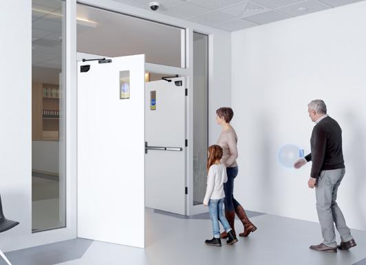
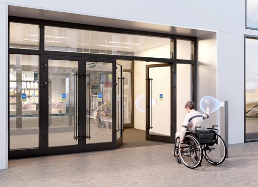
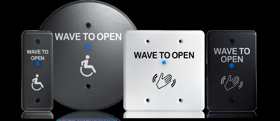
Built-in Knowing Act Device
Two Virtual Push Buttons per sensor provide a non-contact form of door activation without wiring or installing in-wall switches
Adaptive Sensing
High-resolution detection curtains create a reliable solution with the ability to self-adapt as the door opens, preventing false detections from guide rails and tight corridors
Background Independence
LASER technology ensures independence of all types of flooring (pedi-mats, carpet, reflective flooring, wet surfaces, etc.) and the surrounding environment (weather and lighting)
Easy Setup
Hub-less system offers fewer components for a more straightforward setup and installation. While Hand Gesture Setup™ reduces configuration time of the detection field width
This sensor is powered by DC voltage only. If only VAC power is available, a 12V transformer paired with a rectifier must be used. Do not use a 24V transformer and rectifier as this will cause damage to the product.
TECHNICAL SPECIFICATIONS Technology LASER scanner, Time-of-Flight measurement
Detection Mode Presence
Max. Detection Range 13’ (diagonal) with reflectivity of 2% e.g. at 5’ width, max. H = 12’
Recommended Mounting Height 75 – 98"
Opening Angle
Door Leaf Safety
Pinch Zone Safety
Angular Resolution
Curtain 1
Curtain 2
Curtain 3
Curtain 4
Tilt Angles 0 – 5°
Typ. Min. Object Size 3/4” at 13’ in curtain C1
Min. Door Leaf Speed 2°/s
Emission Characteristics (IEC 60825-1) IR LASER: wavelength 905 nm; output power < 0.1mW; Class 1
Supply Voltage* 12 – 24 VDC ±15% (to be operated from SELVcompatible power supplies only)
Power Consumption < 2 W
Response Time
Output
Max. Switching Voltage
Max. Switching Current
Typ. < 120 ms (max. 220 ms)
3 electronic relays (galvanic isolation - polarity free)
42 VAC/VDC 100 mA
Dimensions 5 3⁄4” (L) × 3 1⁄2” (H) × 2 1⁄3” (D)
Mounting base: D + 1 3⁄4” Spacer: D + 1 1⁄2 ”
Materials - Color PC/ASA - black
Protection Degree IP44 (IEC 60529)
LED Signals
1 RGB LED: Detection / Output Status
Temperature Range -13 – 140 °F
Humidity 0 – 95% non-condensing
Vibrations < 2 G
Compliance
PRODUCT SERIES ISO 13849-1 Pl “d”/ CAT2; IEC 60825-1; IEC 62061 SIL 2 UL10 – file # R39071
10LZRFLATSCAN3D-SWBK Left and right sensor kit
10LZRFLATSCAN3D-SWBKU Left and right sensor kit w/ power supply
10LZRFLATSCAN3D-LESWBK Sensor kit for low-energy doors
10LZRFLATSCAN3D-LELBKIT Sensor kit for low-energy doors, left
10LZRFLATSCAN3D-LERBKIT Sensor kit for low-enery doors, right
10LZRFLATSCAN3D-LBK Single sensor kit, left
10LZRFLATSCAN3D-RBK Single sensor kit, right
10LZRFLATSCAN3D-LB Replacement sensor, left
10LZRFLATSCAN3D-RB Replacement sensor, right
10LZRFLATSCANGDA
35.0287
35.0288
35.0236
35.0237
LZR-FLATSCAN glass door accessory
LZR-FLATSCAN 3D SW replacement cover, left
LZR-FLATSCAN 3D SW replacement cover, right
LZR-FLATSCAN 3D SW replacement base, left
LZR-FLATSCAN 3D SW replacement base, right
70.5753 Spacer
20.5433
35.1329
70.5745
LZR-FLATSCAN 3D SW control harness
Primary / Secondary Harness
Sentrex retrofit accessory
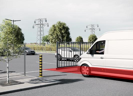
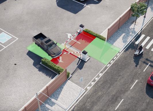
LZR®-H100 LASER SCANNER FOR GATE AND BARRIER APPLICATIONS
Dual Relay Activation
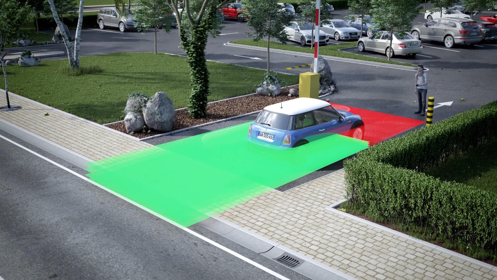
Two relays allow for activation via motion or presence
Effective Alternative to Loop Detectors
Ideal for applications where cutting ground for loops is prohibited, impossible, or expensive
Reliable and Constant Detection
Time-of-Flight, presence based, opto-electronic sensor ensures accurate and immediate detection
TECHNICAL SPECIFICATIONS
Technology LASER scanner, Time-of-Flight measurement
Detection Mode Motion and presence
Max. Detection Range 32’ × 32’ (9 3/4 m)
Min. Detection Field (safety) 1’8” (1 5 m)”
Remission Factor > 2%
Angular Resolution 0.3516°
Emission Characteristics
IR LASER
Red Visible LASER
Wavelength 905 nm;
output power 0.10mW (CLASS 1)
Wavelength 635 nm;
output power 0.95mW (CLASS 2)
Supply Voltage 10 – 35 VDC at sensor terminal
Peak Current at Power-On 1.8 A (max. 80 ms at 35 V)
Power Consumption < 5 W
Response Time
Motion Detection
Presence Detection
Output
Max. Switching Voltage
Max. Switching Current
Switching Time
Output Resistance
Voltage Drop on Output
LED Activity
Blue
Orange
Red/Green (x2)
Dimensions
typ. 200 ms (adjustable)
typ. 20 ms (max. 80 ms)
2 electronic relays (galvanic isolated – polarity free)
35 VDC / 24 VAC
80 mA (resistive)
tON = 5 ms; tOFF = 5 ms
typ 30 Ω
< 0.7 V at 20 mA
Power–on
Error status
Detection / Output Status (green = no detection, red = detection)
3 5⁄8” (W) × 2 3⁄4” (H) × 5” (D)
mounting bracket: + 1⁄2 ”
Cable Length 33’
Materials PC, ASA
Color Black
Rotation Angle on Bracket ±5° (lockable)
Trajectory Detection
Ability to detect vehicle trajectory during approach and departure
Pedestrian Traffic Rejection
Ability to detect or ignore pedestrian traffic
Large Detection Field
Maximum detection field of 32 ft by 32 ft (9 3⁄4 m by 9 3⁄4 m)
Ease of Installation
Teach-in setup via walk path or remote control configuration
Tilt Angle on Bracket ±3°
Degree of Protection NEMA 4 / IP65
Temperature Range -22 – 140 °F (-30 – 60 °C) powered 14 – 140 °F (-10 – 60 °C) unpowered
Humidity 0 – 95% non-condensing
Vibrations < 2 G
Pollution on Front Screens max. 30%; homogenous
Norm Conformity
2006 / 95 / EC: LVD
2004 / 108 / EC: EMC
IEC 60825-1:2007
IEC 61000-6-2:2005
PRODUCT SERIES 2002 / 95 / EC: RoHS
IEC 60529:2001
IEC 60950-1:2005
IEC 61000-6-3:2006
10LZRH100 LASER scanner with highly precise detection zone
10LBA LZR mounting bracket accessory
10INDBRACKET Industrial mounting bracket
10MINIBRACKET Short, adjustable mounting bracket
10LHB LZR housing bracket
10PSMDR2024 DIN rail power supply, 100 – 240 VAC / 24 VDC
10PSST242 Plug-in power supply
10REMOTE Universal remote control for sensor setup
35.1242 30' harness, 8-conductor
LZR®-I30 LASER SCANNER FOR INDUSTRIAL AUTOMATION
3-Dimensional Safety Zone
Four curtains of detection each capable of 360 in by 360 in (30 ft by 30 ft)
Highly Accurate Detections
Detects objects as small as 2 inches at 30 feet away, depending on application
TECHNICAL SPECIFICATIONS Technology LASER scanner, Time-of-Flight measurement
Detection Mode Motion and presence (EN 12453 Typ. E)
Max. Detection Range 30’ × 30’
Remission Factor > 2%
Emission Characteristics
IR LASER
Red Visible LASER
Wavelength 905 nm; output power 0.10mW (CLASS 1)
Wavelength 635 nm; output power 0.95mW (CLASS 2)
Supply Voltage 10 – 35 VDC at sensor terminal (to be operated from SELV compatible power supplies only)
Peak Current at Power-On 1.8 A (max. 80 ms at 35 V)
Power Consumption < 5 W
Response Time Typ. 20 ms; max. 80 ms (+ output activation delay)
Output
Max. Switching Voltage
Max. Switching Current 2 electronic relays (galvanic isolated – polarity free) 35 VDC / 24 VAC 80 mA (resistive)
LED Activity
Blue
Orange
Red/Green (x2)
Dimensions
Housing 10LBA
Energy Savings
Has the ability to ignore dynamic ground conditions and extreme weather
Easily Adjustable
Three visible LEDs for pattern alignment
Test Body Dimensions 700 mm × 300 mm × 200 mm (28" × 12" × 8")
Norm Conformity
2006 / 95 / EC: LVD
2002 / 95 / EC: RoHS
2004 / 108 / EC: EMC
2006 / 42 / EC: MD EN 12453:2000 chapter
5.1.1.6, chapter 5.5.1
Safety device E EN 12978:2009
EN ISO 13849-1:2008 CAT2, Pl “d”; EN 60529:2001
PRODUCT SERIES Power–on
Error status
Detection / Output Status (green = no detection, red = detection)
5” (W) × 2 3/4”(H) × 3 2⁄3 (D) Adds 11⁄20
Cable Length 30’
Materials PC, ASA
Color Black
Rotation Angle on Bracket ±5° (lockable)
Tilt Angle on Bracket ±3°
Degree of Protection
NEMA 4 / IP65
Temperature Range -22 – 140 °F if powered 14 – 140 °F if unpowered
Humidity
Vibrations
0 – 95% non-condensing
< 2 G
Pollution on Front Screens Max. 30%; homogenous
IEC 60825-1:2007
EN 60950-1:2005
EN 61000-6-2:2005
EN 61000-6-3:2006
IEC 61496-1:2009
EN 61496-3: 2008 ESPE Type 2
EN 62061:2005 SIL 2
10LZRI30 LASER scanner with highly precise detection zone
10LBA LZR mounting bracket accessory
10INDBRACKET Industrial mounting bracket
10MINIBRACKET Short, adjustable mounting bracket
10REMOTE Universal remote control for sensor setup
10PSMDR2024 DIN rail power supply, 100 – 240 VAC / 24 VDC
10PS12-24 UL / ULC Listed power supply
10PSVR5T Voltage regulator, 24 VAC / 24 VDC
35.1242 8-conductor cable (30’)
LZR®-MICROSCAN T STAND-ALONE, DOOR-MOUNTED, SWING-DOOR, SAFETY SYSTEM
Easy to Install
Plug-and-play technology utilizing a centralized hub and intuitive LCD interface greatly reduces installation and setup time
Highly Accurate Detection
High resolution, self-adapting detection zones, coupled with reduced uncovered zones create the most accurate and reliable safety sensor
Built-in Troubleshooting
On-board error log ensures easy technical support
Standards Compliant
Fully monitored internally, capable of external monitoring
UL10B/C Listed
Fire-rated for up to three hours
TECHNICAL SPECIFICATIONS
Technology
LASER scanner, Time-of-Flight measurement
Detection Mode Presence
Min. / Max. Door Width
Mounting Height
20 – 48”
(measured from leading edge to sensor LED)
75 – 98”
(measured from finished floor to sensor LED)
Remission Factor > 2%
Angular Resolution
Testbody
Emission Characteristics
2.56°
28" (H) × 12" (W) × 8" (D)
IR LASER Wavelength 905 nm; maximum output pulse power 35 W (Class I)
Supply Voltage
12 – 30 VDC (15 W Class II)
Power Consumption < 15 W
Response Time Typ. 40 ms; max. 80 ms
Output Rating 4 electro-mechanic relays
(galvanic isolated - polarity free)
All outputs Class 2 supply, 12 – 24 VAC, 12 – 30 VDC, max. 15 W
Input Rating 2 optocouplers (galvanic isolated - polarity free) 12 – 30 VDC, max. 15 W
Test Input 8 – 15 VDC
Temperature Range -13 – 121 °F (-25 – 55 °C)
Degree of Protection
Hub: IP20 / NEMA 1
Sensor: IP53 / NEMA 3
Humidity 0 – 95%, non-condensing
Vibrations < 2 G
Materials PC, ASA
Norm Conformity EN 60825-1-Eye-safety class 1 IR LASER (905 nm)
UL10B/C Fire Rated 3 hrs (file #R39071)
Mounting Angle (rotational) 35° fixed
Tilt Angle 0 – 5° (for angles less than 5°, contact Technical Support)
Pollution on Front Screens Maximum 30%, homogenous
PRODUCT SERIES 10LZRMICROSCAN1T Single door kit
(1) left sensor, (1) right sensor, (1) hub, (1) primary harness, (1) secondary harness, (1) door control harness, (1) home switch, (1) door loop / cap kit, (1) sensor spacer
10LZRMICROSCAN1UT (1) 10LZRMICROSCAN1T (1) 10LZRMICROSCAN-UKIT
10LZRMICROSCAN2T Pair/Dual-egress door kit
(2) left sensors, (2) right sensors, (1) hub, (2) primary harnesses, (2) secondary harnesses, (2) door control harnesses, (2) home switches, (2) door loops / cap kits, (2) sensor spacers
10LZRMICROSCAN2UT (1) 10LZRMICROSCAN2T (1) 10LZRMICROSCAN-UKIT
10MICROSCAN-UKIT Universal accessory kit converts Single door kit and Pair/Dual-egress door kit into 10MICROSCAN1UT and 10MICROSCAN2UT (1) power supply (1) ON / OFF / HOLD OPEN switch
OPTIONAL MOUNTING KITS 10MICROSCANMOUNT Center-pivot door mounting kit includes: (1) Left mounting arm (1) Right mounting arm
10MICROSCAN-Y Glass/Fire door mounting kit includes:
(1) 20.5319 - 20” secondary harness
(1) 20.5320 - “Y” cable LZR-MICROSCAN-T hub to LZR-MICROSCAN-T harness
(1) 70.0202 - 26” standard door cord loop
(1) 55.0001 - Door loop end cap for door frame
LZR®-MICROSCAN T STAND-ALONE, DOOR-MOUNTED, SWING DOOR, SAFETY SYSTEM REPLACEMENT COMPONENTS 10LZRMICROLEFTT Left LZR-MICROSCAN T sensor
10LZRMICRORIGHTT Right LZR-MICROSCAN T sensor
10LZRMICROSCANHUB LZR-MICROSCAN T hub
10DOORSWITCH Universal Kit ON / OFF / HOLD OPEN switch
20.5095 Power supply harness
20.5096 EAGLE harness for LZR-MICROSCAN T
20.5222 Door control harness
20.5304 System harness
20.5310 ON / OFF / HOLD OPEN switch jumper
20.5319 Secondary harness for 10MICROSCANMOUNT (20")
20.5320 “Y” cable LZR-MICROSCAN-T hub to LZR-MICROSCAN-T harness
20.5322 LZR-MICROSCAN T plug-n-play harness for Horton 4190
20.5347 Hub to LZR-MICROSCAN T harness (30')
30.5558 Universal kit power supply
30.5580 2-wire switch
35.1326 Primary sensor harness
35.1327 Secondary sensor harness
41.7922 Left pass-through LZR-MICROSCAN T sensor end cap
41.7923 Right pass-through LZR-MICROSCAN T sensor end cap
41.8632 End cap screws
50.0046 Velcro tabs
50.0048 Spacer mount screws
55.0001 Jamb cap kit
50.1818 Spacer mount screws (metal)
50.5282 Spacer mount screws (wood)
50.5283 Home Switch (surface mount)
70.0202 26” standard door cord loop
70.5554 LZR-MICROSCAN T sensor spacer
70.5745 Sentrex retrofit accessory
35.1321 LZR-MICROSCAN T replacement cover
LZR®-S600 LASER SCANNER FOR BUILDING AUTOMATION AND SECURITY
BEA’s Largest Detection Field
Maximum detection range of 82 ft by 82 ft
Safe and Reliable
External, entrapment protection device capable of monitoring with interfaces building management systems
TECHNICAL SPECIFICATIONS
Technology LASER scanner, Time-of-Flight measurement
Detection Mode motion and presence
Detection Range Default: 33’ x 33’ at 2% remission factor (max. 82' x 82')
Angular Resolution 0.3516°
Min. Detected Object Size (typ.)
0.8 in at 10'
1.4 in at 16'
2.8 in at 33' 6.9 in at 82'
Emission Characteristics
IR LASER
Red visible LASER wavelength 905 nm; output power 0.10mW (CLASS 1) wavelength 635 nm; output power 0.95mW (CLASS 2)
Supply Voltage 10 – 35 VDC at sensor side
Power Consumption < 5 W
Peak Current at Power-on 1.8 A (max. 80 ms at 35 V)
Cable Length 33’
Response Time typ. 20 ms (max. 80 ms) + output activation delay
Output
Max. switching voltage
Max. switching current
Switching time
Output resistance
Voltage drop on output
Leakage current
Input
Max. contact voltage
Voltage threshold
Response Time
2 electronic relays (galvanic-isolated – polarity-free)
35 VDC / 24 VAC
80 mA (resistive)
t ON = 5 ms; t OFF = 5 ms
typ 30 Ω
< 0.7 V at 20 mA < 10 µA
2 optocouplers (galvanic-isolated – polarity-free)
30 VDC (over-voltage protected)
Log. Active High: > 8 VDC Log. Active Low: < 3 VDC
Monitoring Input < 5 ms
LED Activity
Blue Orange
Red/Green (x2)
Dimensions
Reduce False Detections High immunity to environmental interferences
Eliminates False Detections
Has the ability to ignore dynamic ground conditions and extreme weather
Mounting Angles on Bracket
Rotation Angles on Bracket
-45°, 0°, 45°
-5 – 5° (lockable)
Tilt Angles on Bracket -3 – 3°
Protection Degree NEMA 4 / IP65
Temperature Range powered: -22 – 140 °F (-30 – 60 ºC) unpowered: 14 – 140 °F (-10 – 60 ºC)
Humidity 0 – 95% non-condensing
Vibrations < 2G
Pollution on Front Screen max. 30%, homogenous
Norm Conformity
PRODUCT SERIES 2006/95/EC: LVD; 2002/95/EC: RoHS; 2004/108/ EC: EMC; IEC 60529:2001; IEC 60825-1:2007; IEC 60950-1:2005; IEC 61000-6-2:2005; IEC 610006-3:2006
10LZRS600 Presence detection for building automation and security
10LBA LZR mounting bracket accessory
10INDBRACKET Industrial mounting bracket
10MINIBRACKET Short, adjustable mounting bracket
10REMOTE Universal remote control for sensor setup
10PSMDR2024 DIN rail power supply, 100 – 240 VAC / 24 VDC
10PS12-24 UL / ULC Listed power supply
10PSVR5T Voltage regulator, 24 VAC / 24 VDC
35.1242 8-conductor cable (30’)
Power–on Error status
Detection / Output Status
(green = no detection, red = detection)
3 5 ⁄ 8”× 2 3 ⁄4”× 5” (W × H × D)
mounting bracket: + 1⁄ 2 ”
Material PC/ASA
Color Black
MICROCELL ONE PHOTO BEAMS FOR PEDESTRIAN, AUTOMATIC DOORS
Enhanced Safety on Pedestrian Doors
Easy installation on all types of pedestrian doors
User-Friendly Setup
LED indicators assist in setting up alignment
Standard Compliant
Can be mounted as low as 12 inches from the floor
TECHNICAL SPECIFICATIONS Technology Active infrared
Detection Mode Presence (beam interruption)
Min. Mounting Height 12” from floor
Min. Distance Between Beams 12” (crossed beams)
Min. Range of Detection 3’
Max. Range of Detection 15’
Alignment Tolerance 8°
Response Time ≤ 40 ms
Hold Time 300 ms
Supply Voltage 12 – 24 VAC; ±10% 12 – 24 VDC; -5% / 30%
Current Consumption < 100 mA
Output Contact Rating
Max. Contact Voltage
Max. Contact Current
Max. Switching Power 1 relay (NC / NO contacts) 50 VAC/VDC 1 A 30 W (DC) / 60 VA (AC)
Operating Temperature -30 – 131 °F
Immunity Sunlight
Incandescent Lamp
Electromagnetic Compatibility
Dimensions
Head Body Head Harness
75,000 lux 25,000 lux at 8° angle According to 89 / 336 EEC
Control Board < 15⁄32" (L embed) × 15⁄32” (ø) 5⁄8” (ø) 3 1⁄33” (W) × 1 2⁄25” (H) × 2 1⁄33” (D)
Cable Length 18’ (standard) 32’ (optional)
Material ABS
Degree Of Protection NEMA 4 / IP65 (beam heads)
Ideal for Wide Doors
Maximum range of detection of 15 feet with an 8° alignment tolerance
Compatible with BEA’s BODYGUARD-T
Capable of meeting ANSI 156.10 standard for swing-door safety when paired with BEA’s BODYGUARD-T
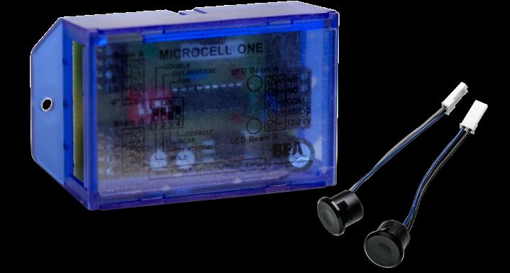
PRODUCT SERIES 10MICROCELL1S Single safety beam with control box (18’ cable)
10MICROCELL1SL Single safety beam with control box (32’ cable)
10MICROCELL1D Double safety beam with control box (18’ cable)
10MICROCELL1DL Double safety beam with control box (32’ cable)
10MICROCELLADAPTER Wiring kit to retrofit BEA MICROCELL beams where Optex beams are currently installed
Must order with part number 03.0109 and the 10MICROCONTROL
10MICROCONTROL MICROCELL control box
10MICRO1SADAPT
MICROCELL single beam adapter kit allows for MICROCELL beams to replace Optex beams without running a new cable
(1) set of MICROCELL emitter and receiver heads, (1) 10MICROCELLADAPTER, (1) 10MICROCONTROL
10MICRO1DADAPT MICROCELL double beam adapter kit allows for MICROCELL beams to replace Optex beams without running a new cable
(2) sets of MICROCELL emitters and receiver heads, (2) 10MICROCELLADAPTER, (1) 10MICROCONTROL
20.0031
20.0045
20.0055
20.0056
3” Emitter and 3” Receiver (ordered as a set)
Jamb cap kit with screws
Emitter and Receiver set (32’ cable)
Emitter and Receiver set (18’ cable)
R2E-100 FOCUSED ACTIVE INFRARED, REQUEST-TO-EXIT SENSOR
Standards Compliant
UL294 and ULCS319 Listed
Define Your Tilt Angle
Adjustable tilt angle from zero to 10°
Customizable Detection Zones
Adjustable detection range from 20 to 48 inches
TECHNICAL SPECIFICATIONS
Detector Type
Focused, active infrared
Supply Voltage 12 – 24 VAC/VDC; ±10% at 60 Hz
Current
Sounder OFF
Sounder MAX VOLUME
Temperature (UL Install)
155 mA
200 mA
32 – 120 °F (0 – 49 °C)
Temperature -20 – 120 °F (-29 – 49 ºC)
Humidity
(ULCS319 Installation) (UL294 Installation)
0 – 93% non-condensing
0 – 85% non-condensing
Detection Range* 20 – 48”, adjustable via potentiometer
Relay 2 Form “C” contact sets;
Relay Hold Time
1.3 A at 24 VAC / 30 VDC
0.5 – 60 s, adjustable via potentiometer
Sounder 85 dB max, adjustable volume
LEDs Green, red, yellow, orange
REX Input DRY contact, NO
Card Reader Input DRY contact, NC
Door Position Switch Input DRY contact, NO
Dimensions 6 7⁄10” (W) × 1 7⁄10” (D) × 2” (H)
Materials ABS, PC
Wiring Interface JST (14-pin) with 4’ cable
Norm Conformity UL294, ULCS319
FCC Part 15 B
* R2E-100 can accommodate swing doors up to 7 feet high.
Low-Profile Mounting
Low-profile sensor mounts on or above the door frame
Multiple Inputs
Three DRY auxiliary inputs: a push button or other request-to-exit device, a card reader or other request-to-enter device, and a door position switch
PRODUCT SERIES 10R2E-100
UL / ULC Listed, active infrared, request-to-exit detector specifically designed for access control applications
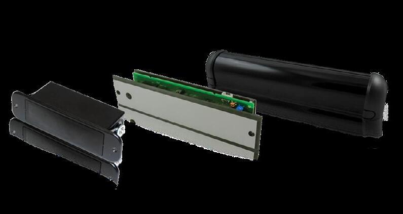
SUPERSCAN-T DOOR MOUNTED, ACTIVE INFRARED, SAFETY SENSOR
Fit to the Application
Housing available up to 102 inches in length; can be field cut to desired door width
ANSI Compliant
Capable of meeting ANSI 156.10 standard for swing-door safety when coupled with BEA’s BODYGUARD-T
Functional Design
Designed to mount at the top of the door to reduce accidental damage
TECHNICAL SPECIFICATIONS
Technology Active infrared with background suppression
Detection Mode Presence
Measurement of Distance Triangulation
Power Supply 12 – 24 VAC/VDC ±10%
Output Interface; Relay Relay – max. contact rating: 1A at 30 V (resistive)
Detection Range 0 – 8’
Distance Adjustment 2 – 8’ (rotating cam with linear adjustment)
Max. Mounting Height 8’
Detection Signal Duration Infinite presence detection
Detection Time < 50 ms
Output Hold Time Potentiometer range: 0.1 – 4.5 s
Operating Temperature Range -30 – 140 °F
PCB Dimensions
Primary
Secondary
10.91” (W) × 1.5” (H)
8.75” (W) × 1.5” (H)
Connector to Door Controller 8-position screw terminal on Primary PCB
Primary-to-Secondary Connection Flat-ribbon cable with connectors and key lock
Max. Number of Secondaries 8
Functions Selection Detection mode: NO or NC Normal mode or Background Analysis mode
Customizable
Can be set to background analysis mode to reduce the chance of false detection from faulty environmental situations
Standards Compliant
Capable of external monitoring
PRODUCT SERIES
See page 39...
SUPERSCAN-T INDUSTRIAL ACTIVE INFRARED, SAFETY SENSOR
Fit to the Application
Housing available up to 96 inches; can be field-cut to desired door width
User-Defined Detection Zones
Detection zone of 24 to 96 inches
Adjustable Detection Zone
Can be set to background analysis mode to reduce the change of false detection from faulty environmental situations
TECHNICAL SPECIFICATIONS
Technology Active infrared with background suppression
Detection Mode Presence
Measurement of Distance Triangulation
Power Supply 12 – 24 VAC/VDC ±10%
Output Interface; Relay Relay – max. contact rating: 1A at 30 V (resistive)
Detection Range 0 – 8’
Distance Adjustment 2 – 8’ (rotating cam with linear adjustment)
Max. Mounting Height 8’
Detection Signal Duration Infinite presence detection
Detection Time < 50 ms
Output Hold Time Potentiometer range: 0.1 – 4.5 s
Operating Temperature Range -30 – 140 °F
PCB Dimensions
Primary
Secondary
10.91” (W) × 1.5” (H)
8.75” (W) × 1.5” (H)
Connector to Door Controller 8-position screw terminal on Primary PCB
Primary-to-Secondary Connection Flat-ribbon cable with connectors and key lock
Max. Number of Secondaries 8
Functions Selection Detection mode: NO or NC Normal mode or Background Analysis mode
Customizable Hold Time
Relay hold time can be adjusted from 0.1 to 4.5 seconds
Standards Compliant
Capable of external monitoring
PRODUCT SERIES
See page 39...
SUPERSCAN-T / INDUSTRIAL ACTIVE INFRARED, SAFETY SENSOR PRODUCT SERIES 10SSTI 1 Primary
34 1⁄2” end cap to end cap (for 36” doors)
10SSTICUSTOM 1 Primary
Custom Length (13” min.)
10SSTI40 1 Primary
40” end cap to end cap (for 42” doors)
10SSTI42 1 Primary 42” end cap to end cap (for 44” doors)
10SSTI48 1 Primary 48” end cap to end cap (for 50”+ doors)
10SSTII 1 Primary + 1 Secondary
34 1⁄2” end cap to end cap (for 36” doors)
10SSTIICUSTOM 1 Primary + 1 Secondary
Custom Length (24 1 2” min.)
10SSTII40 1 Primary + 1 Secondary 40” end cap to end cap (for 42” doors)
10SSTII42 1 Primary + 1 Secondary 42” end cap to end cap (for 44” doors)
10SSTII44 1 Primary + 1 Secondary 44” end cap to end cap (for 46” doors)
10SSTII48 1 Primary + 1 Secondary 48” end cap to end cap (for 50”+ doors)
10SSTIII 1 Primary + 2 Secondaries 34 1⁄2” end cap to end cap (for 36” doors)
10SSTIIICUSTOM 1 Primary + 2 Secondaries
Custom Length (34 1 2” min.)
10SSTIVCUSTOM 1 Primary + 3 Secondaries
Custom Length (46 1 2” min.)
10SSTSECONDARY SUPERSCAN-T secondary unit (no housing) includes ribbon connector
10SSTPRIMARY SUPERSCAN-T primary unit (no housing)
10SSQD Quick disconnect for SUPERSCAN-T one needed per door
10SSHARDWARE SUPERSCAN-T hardware kit
Includes cord sheath, jamb caps with screws, and end caps with screws
10CAPKIT (1) left + (1) right end caps and mounting screws
30.0015
41.3879
55.0001
70.0025
70.0048
70.0049
70.0050
70.0138
70.0202
70.0203
70.0304
70.0319
70.0320
70.0321
Ribbon connector cable connects primaries and secondaries
Adjustable mounting clips for primary and secondary
Door cord jamb cap and screw
Aluminum housing, ordered per inch (stocked in 102” lengths)
Aluminum housing cut to 38 1⁄2” (for a 40” SUPERSCAN-T)
Aluminum housing cut to 40 1⁄2” (for a 42” SUPERSCAN-T)
Aluminum housing cut to 46 1⁄2” (for a 48” SUPERSCAN-T)
Lens piece, ordered per inch (stocked in 102” lengths)
Standard 26” SUPERSCAN-T door cord sheath, ordered per piece
Lens piece cut to standard 33” lens (for a 34 1⁄2” SUPERSCAN-T)
SUPERSCAN-T hardware kit
Includes cord sheath and jamb caps with screws
Lens piece cut to 38 1⁄2” (for a 40” SUPERSCAN-T)
Lens piece cut to 40 1⁄2” (for a 42” SUPERSCAN-T)
Lens piece cut to 46 1⁄2” (for a 48” SUPERSCAN-T)
BEAMBOX ACTIVE INFRARED, MOTION AND PRESENCE SENSOR
Off-Door Presence Detection
Three rows of five infrared spots ideal for unique off-door applications
Multiple Preset Detection Zones
Four infrared immunity modes and nine unique preset patterns are available
TECHNICAL SPECIFICATIONS Technology Active infrared with background analysis
Detection Mode Motion and presence
Optical Features 15 independent IR spots with a diameter of typ. 0.43”
Maximum Mounting Height 8 1⁄5’ (flush mounting)
Tilt Angles
Detection Zone
0 – 20° vertical in steps of 5°
3 3⁄10’ (W) × 3 9⁄10’ (D) at mounting height 6 1/2’ with tilt angle at 20°
Reaction Time < 100 ms
Supply Voltage
12 – 30 VAC ±10%; 12 – 45 VDC ±10%
Power Consumption < 3 W (VA)
Output
Max. Contact Voltage
Max. Contact Current
Max. Switching Power
Monitoring Input
Input Voltage
Input Current
Relay (free of potential change-over contact) 42 VAC – 60 VDC
1 A (resistive)
30 W (DC) / 60 VA (AC)
Optocoupled (free of potential) 10 – 24 VDC < 10 mA (at 24 V)
Connection (Sensor Side) Unpluggable, integrated 7-pin connector
Hold Time
0.5 – 9 s (adjustable)
LEDs Red and green
Mains Frequency 50 – 60 Hz
Temperature Range -13 – 126 °F (operating); -22 – 140 °F (storage)
Degree of Protection
IP41
Dimensions 5 1/2” (W) × 1 1/2” (H) × 2 1 5 ”
Weight 3 1/2 oz
Enclosure Material PC
Color Black
Cable Length 8’
Customizable to Your Application
Typical detection area of 3 1∕4 by 3 1∕4 feet when mounted at a height of 7 feet
Low-Profile Design
Recessed mounting for low-profile applications
PRODUCT SERIES 10BEAMBOX Uses a 3 × 5 matrix of infrared spots (15 total) where each can be individually activated
Monitoring capable
10REMOTE Universal remote control for sensor setup 10SPOTFINDER Active-infrared-spot finder
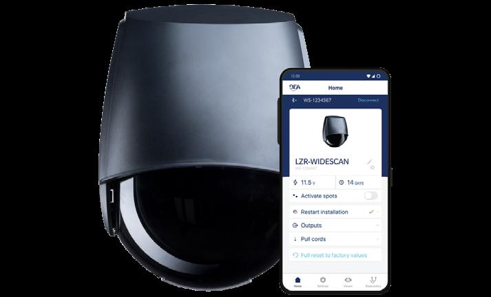
Easily configure sensor settings with the LZR-WIDESCAN mobile app. The mobile app provides a complete view of sensor settings, from field configurations to immunity.
IS40 / XL MOTION AND PRESENCE SENSORS FOR INDUSTRIAL DOORS
Energy Savings
Bidirectional, unidirectional approach, and unidirectional depart microwave detection options
Adjustable Detection Settings
Six modes of detection filtering are available for microwave immunity, as well as pedestrian and parallel traffic rejection
Customizable Patterns
Nine unique infrared patterns capable of highly flexible presence detection in any industrial environment
TECHNICAL SPECIFICATIONS
Technology Microwave Doppler radar Active infrared
Detection Mode Motion Presence
LED Activity Green (activation relay) Red (presence relay)
Transmitter
Frequency / Wavelength 24.150 GHz 875 nm
Transmitter
Power Density < 5mW / cm² < 250 mW / m²
Max. Detection Field IS40 IS40XL 13’ × 16 1/2‘ 13’ × 6 1/2‘* 10’ × 10’** 7 1/2‘ × 7 1/2‘***
Output Hold Time 0.5 – 9 s 0.5 s
Min. Detection Speed 2 in/s 0 in/s to activate detection
Tilt Angle -8 – 22° (relative to sensor face) 15 – 45°
Mains Frequency 50 – 60 Hz
Power Consumption < 3.5 W
Output
Max. Contact Voltage
Max. Contact Current
Max. Switching Power 2 relays (free of potential change-over contact) 42 VAC/VDC 1 A (resistive) 30 W (DC) / 48 VA (AC)
Installation Height IS40 IS40XL 8 – 16’ 6 1/2 – 11 1/2’
Temperature Range -22 – 140 °F
Dimensions 3 3/4” (W) × 4” (H) × 5” (L)
Materials ABS, PC
Cable Length 32’
Degree of Protection NEMA 4 / IP65
Norm Conformity
* Determines field size
R&TTE: 1999 / 5 / EC EMC 2004 / 108 / EEC
** Measured at 30° / Field size 9 / Mounting Height: 16’, XL: 11 1⁄2’
*** Zone detected with the SPOTFINDER (i.e. slightly larger than the effective detection field)
Reduce False Detections
Adjustable infrared immunity modes mitigate environmental disturbances such as subtle door vibrations, light, and sun
Programmable Via Remote
Remote control programming enables user to quickly and safely make changes from the ground (sold separately)
PRODUCT SERIES 10IS40 Dual technology industrial sensor utilizing microwave motion and active infrared presence detection
10IS40XL Dual technology industrial sensor utilizing microwave motion and active infrared presence detection for low mounting heights
10INDBRACKET Industrial mounting bracket
10MINIBRACKET Short, adjustable mounting bracket
10SPOTFINDER Active infrared spotfinder
10REMOTE Universal remote control for sensor setup
35.1566 8-pin conductor cable (30’)
IXIO-DT1 MOTION AND PRESENCE SENSOR FOR AUTOMATIC, SLIDING DOORS
Energy Efficient
Ten microwave activation sensitivity settings and three infrared safety immunity settings
Precise Presence Detection
Two 24 spot, high density, infrared, safety curtains providing precise presence detection
Easily Adjustable
Four visible, red, alignment spots are projected on the ground to assist in precise IR curtain adjustment
Ease of Setup
Intelligent programming and troubleshooting via a menu-driven LCD
Standards Compliant
Fully monitored internally, capable of external monitoring
TECHNICAL SPECIFICATIONS
Technology Microwave Doppler radar Active infrared
Detection Mode Motion Presence
Transmitter Frequency
Transmitter Radiated
24.150 GHz N/A
Power < 20 dBm EIRP N/A
Transmitter Power Density < 5 mW / cm² N/A
Spot Size N/A 2” × 2”
Max. Number of Spots N/A 24 per curtain
Max. Number of Curtains N/A 2
Output
Max. Contact Voltage
Max. Contact Current Hold Time
Test Input
Sensitivity
Response time on test request:
Electro-mechanical-relay (potential and polarity free)
30 VDC 1 A
0.5 – 9 s (user adjustable)
Low: < 1 V
High: > 10 V (max. 30 V)
< 5 ms (typical)
Solid-state-relay (potential and polarity free)
42 VAC/VDC
400 mA
0.3 – 1 s
Supply Voltage 12 – 24 VAC ±10%; 12 – 30 VDC ±10% (to be operated from SELV compatible power supplies only)
Power Consumption < 2.5 W
Mounting Height 6 1/2 – 11 1/2’
Temperature Range* -13 – 131 °F
Degree of Protection
0 – 95% relative humidity, non-condensing
IP54
Applicable Directives R&TTE 1999 / 5 / EC
LVD 2006 / 95 / EC
MD 2006 / 42 / EC
ROHS 2 2011 / 65 / EU
Dimension 10 3⁄5“ (W) × 2 1/4” (H) × 2 1/4” (D)
Cable Length 10’
Norm Conformity ISO 13849-1:2008 PL «c» CAT. 2 (under the condition that the door control system monitors the sensor at least once per door cycle) IEC 61496-1:2012 ESPE Type 2
* LCD screen is operational from 14 to 131 °F. The sensor may still be programmed in colder temperatures, but with the remote control.
PRODUCT SERIES 10IXIODT1
Dual-technology sensor for sliding doors 10ICA IXIO ceiling accessory
10IMB IXIO bracket accessory
10URA Universal rain accessory
10CDA IXIO curved door accessory
10IXIOSPACER IXIO spacer (black)
35.1286 IXIO replacement cover (black)
35.1302 IXIO replacement cover (white)
35.1303 IXIO replacement cover (silver)
10RETROFITSPACER Retrofit Spacer Kit (spacer, 2 1⁄2" harness, 9" harness)
20.5349
20.5359
20.5302
70.0173
70.0182
10MINIBRACKET
IXIO / ULTIMO control harness (10')
Wire harness (30’)
Optex-to-IXIO conversion harness
IXIO wide antenna
IXIO narrow antenna
Short, adjustable mounting bracket
10REMOTE Universal remote control for sensor setup
IXIO-DT1 INDUSTRIAL MOTION AND PRESENCE SENSOR FOR INTERIOR, INDUSTRIAL DOORS
Energy Efficient
Ten microwave activation sensitivity settings and three infrared safety immunity settings
Enhanced Accessibility
PRM mode for applications frequently used by persons with reduced mobility (e.g. wheelchair or elderly traffic)
Precise Presence Detection
Two 24-spot, high-density, infrared safety curtains providing precise presence detection
TECHNICAL SPECIFICATIONS
Detection Mode Motion
minimum detection speed: 2 in/s Presence typical response time: < 200 ms (max. 500 ms)
Technology Microwave doppler radar
Transmitter frequency: 24.150 GHz
Transmitter radiated power: < 20 dBm EIRP
Transmitter power density: < 5 mW/cm
Mounting Height
Sensor
Active infrared with background analysis
Spot: 2” × 2” (typ)
Number of spots: max. 24 per curtain Number of curtains: 2
Easily Adjustable
Four visible, red, alignment spots are projected on the ground to assist in precise IR curtain adjustment
Ease of Setup
Intelligent programming and troubleshooting via a menu-driven LCD
Standards Compliant
Fully monitored internally, capable of external monitoring
6 1/2 – 11 1/2’
local regulations may impact acceptable mounting height (pedestrian applications only)
Temperature Range -13 – 131 °F
Output
Relay 1
Relay 2
Test / Monitoring
Input
0 – 95% relative humidity, non-condensing
LCD screen is operational from 14 – 131 °F. The sensor may still be programmed in colder temperatures, but with the remote control.
Electromechanical relay (potential and polarity free)
Max. contact current: 1 A
Max. contact voltage: 30 VAC
Adjustable hold time: 0.5 – 9 s
Solid-state relay (potential and polarity free)
Max. contact current: 100 mA
Max. contact voltage: 42 VDC / 30 VAC
Sensitivity:
Low: < 1 V
High: > 10 V (max. 30 V)
Response time on test request: typical < 5 ms
Supply Voltage 12 – 24 VAC ±10%; 12 – 30 VDC ±10%
(to be operated from SELV compatible power supplies only)
Power
Consumption < 2.5 W
Noise < 70 dB
Degree of
Protection
IP54
FCC Certification FCC: G9B-100606 IC: 4680A-100606
Compliance ISO 13849 PL «c» CAT. 2 (under the condition that the door control system monitors the sensor at least once per door cycle)
PRODUCT SERIES 10IXIODT1INDUS Dual-technology, industrial sensor utilizing microwave motion and active infrared presence sensor. Includes 30’ cable.
10ICA IXIO ceiling accessory
10IMB IXIO bracket accessory
10URA Universal rain accessory
10CDA IXIO curved door accessory
10IXIOSPACER IXIO spacer (black)
35.1286 IXIO replacement cover (black)
35.1302 IXIO replacement cover (white)
35.1303 IXIO replacement cover (silver)
10RETROFITSPACER Retrofit Spacer Kit (spacer, 2 1⁄2" harness, 9" harness)
20.5349 IXIO / ULTIMO control harness (10')
20.5359 Wire harness (30’)
20.5302 Optex-to-IXIO conversion harness
70.0173 IXIO wide antenna
70.0182 IXIO narrow antenna
10MINIBRACKET Short, adjustable mounting bracket
10REMOTE Universal remote control for sensor setup
IXIO-DT1V MOTION AND PRESENCE SENSOR WITH CAMERA FOR AUTOMATIC, SLIDING DOORS
Additional Camera Functionality
Provides an SDTV camera that shoots 30 frames of footage per second
Easily Integrates
Integrates with building surveillance systems
Upgrade IXIO In the Field
Video replacement kit available to upgrade any IXIO in the field
Energy Efficient
Ten microwave, activation sensitivity settings and three infrared safety immunity settings
Enhanced Accessibility
PRM mode for applications frequently used by persons with reduced mobility (e.g. wheelchair or elderly traffic)
Precise Presence Detection
Two 24-spot, high-density, infrared safety curtains providing precise presence detection
Standards Compliant
Fully monitored internally, capable of external monitoring
TECHNICAL SPECIFICATIONS (SENSOR)
Technology
Microwave Doppler radar Active infrared
Detection Mode Motion Presence
Transmitter Frequency 24.150 GHz N/A
Transmitter Radiated Power < 20 dBm EIRP N/A
Transmitter Power Density < 5 mW / cm² N/A
Spot Size N/A 2” × 2”
Max. Number of Spots N/A 24 per curtain
Max. Number of Curtains N/A 2
Output
Max. Contact Voltage
Max. Contact Current Hold Time
Test Input
Sensitivity
Response time on test request:
Electro-mechanical-relay (potential and polarity free)
30 VDC 1 A 0.5 – 9 s (user adjustable)
Low: < 1 V; High: > 10 V (max. 30 V) < 5 ms (typical)
Solid-state-relay (potential and polarity free)
42 VAC/VDC 400 mA 0.3 – 1 s
Supply Voltage* 12 – 24 VAC ±10%; 12 – 30 VDC ±10%
Power Consumption < 2.5 W
Mounting Height 6 1/2 – 11 1/2’
Temperature Range** -13 – 131 °F 0 – 95% relative humidity, non-condensing
Degree of Protection IP54
Norm Conformity
R&TTE 1999 / 5 / EC LVD 2006 / 95 / EC
MD 2006 / 42 / EC ROHS 2 2011 / 65 / EU
Dimension 10 3⁄5“ (W) × 2 1/4” (H) × 2 1/4” (D)
Cable Length 10’
* To be operated from SELV-compatible power supplies only
** LCD screen is operational from 14 to 131 °F. The sensor may still be programmed in colder temperatures, but with the remote control.
TECHNICAL SPECIFICATIONS (CAMERA)
Voltage Regulator 6.6 – 36 VDC ±10%, 6 – 28 VAC ±10%
Operating Temperature -22 – 140 °F (max. RH: 95%)
Video Output 1.0 (Vp-p) / 75Ω
Image Sensor CMOS
Horizontal Resolution 480 TVL
NTSC Output 720 (H) × 480 (W)
Sync System Inter-Sync Frame Rate 30 fps
Minimum Illumination 0.01 LUX
AE Control Auto
Gain Control Auto
Electronic Shutter 1 s ~ 1/10,000 s
S/N Ratio > 50 dB
AWB Auto
PRODUCT SERIES 10IXIODT1V IXIO-DT1 with integrated video 10IMB IXIO bracket accessory
10CDA IXIO curved door accessory
10IXIOSPACER IXIO spacer (black)
10RETROFITSPACER Retrofit Spacer Kit (spacer, 2 1⁄2" harness, 9" harness)
20.5349 IXIO / ULTIMO control harness (10')
20.5359 Wire harness (30’)
20.2009 IXIO-DT1V camera harness and power supply (8')
70.0173
70.0182
IXIO wide antenna
IXIO narrow antenna
10MINIBRACKET Short, adjustable mounting bracket
10REMOTE Universal remote control for sensor setup
LOOKING OUT FOR YOU ULTIMO LZR®-WIDESCAN MOTION, PRESENCE, AND SAFETY SENSOR FOR INDUSTRIAL DOORS
Easy Setup
Utilize mobile app to easily configure sensor settings (available on the Apple App Store and Google Play Store)
Energy Efficient
Promotes energy savings by reducing false detections and unnecessary door cycling, helping to regulate HVAC
Virtual Pull Cord
Virtual pull-cord function can differentiate between pedestrian and vehicle traffic and can provide pulse-on-stop activation
TECHNICAL SPECIFICATIONS
Technology LASER scanner, Time-of-Flight measurement (7 LASER curtains)
Detection Mode Motion, presence, height, and speed
Max. Detection Field Width: 1.2 x mounting height Depth: 1.2 x mounting height (adjustable depending on user settings)
Thickness of First Curtain 1/4”
Typ. Mounting Height 6’6” – 32’
Min. Reflectivity Factor > 2% (of floor and object) (measured at max. 19’6” in safety field)
Typ. Minimum Object Size 6” at 19’6” (in proportion to object distance)
Testbody 27 1/2” × 11 3/4” × 7 3/4”
Emission Characteristics
IR LASER
Red Visible LASER
Wavelength 905 nm; output power 0.10mW (CLASS 1)
Wavelength 635 nm; output power 0.95mW (CLASS 2)
Supply Voltage 12 – 24 VAC -10/+20%
12 – 30 VDC ±10% at sensor terminal
Power Consumption < 2.5 W (heating = OFF) < 10 W, max 15 W (heating = ECO or AUTO)
Response Time Typ. 230 ms; Max. 800 ms (depending on immunity settings)
Output 2 solid-state relays (galvanic isolation, polarity free)
24 VAC / 30 VDC (max. switching voltage)
100 mA (max. switching current)
- in switching mode: NO / NC - in frequency mode: pulsed signal (f= 100 Hz ±10%)
1 electro-mechanic relay (galvanic isolation, polarity free)
42 VAC/VDC (max. switching voltage)
500 mA (max. switching current)
Input 30 VDC (max. switching voltage)
low < 1 V
high > 10 V (voltage threshold)
Bluetooth Communication Operating bandwidth: 2402 - 2480 MHz
Max. transmitted power: 12 dBm
Alternative Solution
Ideal for replacing costly and labor-intensive induction loop and pull-cord solutions
Visible Spots
Two visible LASER alignment spots ensure accurate pattern placement
Dimensions 7 3/4” (H) × 6” (W) × 4” (D) (approx.)
Materials / Color PC, ASA / Black
Protection Degree NEMA 4 / IP65
Temperature Range -22 – 140 °F
Rotation Angles on Bracket 45° to the right 15° to the left (both directions lockable)
Tilt Angles on Bracket -10 – 5°
LED Activity 2 tri-colored LED: output status / remote control response / error signals
1 blue LED: Bluetooth status
Compliance EN 300 328 V2.2.2, EN 301 489-1 V2.2.2, EN 301 489-17 V3.2.0, EN 60825-1:2014, EN 62311:2008; CSA/UL62368-1
PRODUCT SERIES 10LZRWIDESCAN Motion, presence, and safety sensor
10WBA Universal mounting bracket
10WBAMOUNT
Universal mounting bracket plate
10INDBRACKET Industrial mounting bracket
ADAPTER PLATE KIT (10.1311) IS REQUIRED
10MINIBRACKET Short, adjustable mounting bracket
10.1311
35.1554
35.1555
41.8838
35.0245
10PSMDR2024
10REMOTE
Adapter plate kit
30’ cable
50’ cable
LZR-WIDESCAN replacement base
LZR-WIDESCAN replacement cover
DIN rail power supply, 100 – 240 VAC / 24 VDC
Universal remote control for sensor setup
ULTIMO AUTOMATIC SLIDING DOOR SENSOR WITH EXTENDED AND ENHANCED SAFETY
Enhanced Safety
Positioning the inner, infrared safety curtain through the threshold allows for sustained presence detection in the door opening
When directed through the threshold, the inner, infrared safety curtain provides presence detection while the door is fully open and partial detection during the closing door cycle
Easy Installation
Eight visible, red, alignment spots are projected onto the ground, verifying the location of the infrared curtains and helping to increase the accuracy of setup
Sensors automatically synchronize infrared frequency with ULTI-SYNC functionality, streamlining installation and retrofit applications*
Convenient Programming
Easily define the microwave pattern shape, adjust the infrared curtain width, and review troubleshooting diagnostics via a menudriven LCD
Extended Safety
Three infrared curtains offer deeper and broader safety coverage in front of the door panels
Standards Compliant
Fully monitored internally, capable of external monitoring complying with ANSI 156.10
* ULTI-SYNC is cross-compatible with BEA and other sliding door sensors on the market.
TECHNICAL SPECIFICATIONS
Mounting Height 6'6" – 11'6"
Detection Mode Motion and presence
Temperature Range* -13 – 131 °F
0 – 95% relative humidity, non-condensing
Technology Microwave Doppler radar and active infrared (AIR) with background analysis
Radar Detection Speed (min) 2 in/s
AIR Response Time (typ.) < 200 ms (max. 500 ms)
Radar Transmitter
Frequency
Radiated Power
Power Density
Lobe Angles
AIR Spots
Size
Number of Spots
Number of Curtains
Curtain Angles
Relay Output 1
Max. Contact Voltage
Max. Contact Current
Hold Time
Optofet Output 2
Max. Contact Voltage
Max. Contact Current
Hold Time
Test / Monitoring Input
Sensitivity
Response Time on Request
Supply Voltage
24.150 GHz
< 20 dBM EIRP
< 5 mW / cm² 0 – 45º (typical adjustment), default 25º
2” × 2” (typ.) max. 32 per curtain
3
-3 – 11º, default 0º
Electro-mechanical-relay (potential and polarity free)
30 VDC
1 A
0.5 – 9 s
Solid-state-relay (potential and polarity free)
42 VAC/VDC
400 mA
0.3 – 1 s
Low: < 1 V; High: > 10 V (max. 30 V)
Typical: < 5 ms
12 – 24 VAC ±10%
12 – 30 VDC ±10%
Power Consumption < 3.2 W
Cable Length / Gauge 10’ / 26 AWG
Degree of Protection IP54
Norm Conformity R&TTE 1999 / 5 / EC
MD 2006 / 42 / EC LVD 2006 / 95 / EC ROHS 2 2011 / 65 / EU
* LCD screen is operational from 14 to 131 °F. The sensor may still be programmed in colder temperatures, but with the remote control.
PRODUCT SERIES 10ULTIMO Dual-technology sensor for sliding doors
10RETROFITSPACER
Retrofit Spacer Kit (spacer, 2 1⁄2" harness, 9" harness)
10ULTIMOSPACER ULTIMO spacer
10URA
10UMB
10.1351
20.5349
Universal rain accessory
ULTIMO mounting bracket
ULTIMO replacement cover
IXIO / ULTIMO control harness (10')
10REMOTE Universal remote control for sensor setup
LZR®-U920 / U921 COMPACT, RAW DATA, LASER SCANNER Background Independent
Background or substrate has limited effect on measurements
LASER-Based Measurements
Measurement range: up to 213 ft (65 m)
TECHNICAL SPECIFICATIONS Technology
Measurement Range
LASER scanner, Time-of-Flight measurement
30' (10 m) at 2% remission factor
98' (30 m) at 10% remission factor
213' (65 m) max.
Number of Points/Plane Max. 274
Number of Planes
LZR®-U920
LZR®-U921
Angular Resolution
4 1
Max. 0.3516°
Angular Coverage Max. 96°
Rotating Speed 900 turns / min
Scanning Frequency
LZR®-U920
LZR®-U921 15 Hz 60 Hz
Serial Communication Type
Interface
Communication Mode
Data Transmission Speed
Topology
Symbol Coding File Type Asynchronous RS 485
Half-duplex (U920,U921) 460800 bit / sec (max. 921600 bit / sec)
Point-to-point 1 start bit, 1 stop bit, no parity bit 8 bits
Remission Factor > 2%
Emission Characteristics
IR LASER
Visible LASER
Peak Current at Power-on
Wavelength 905 nm; output power 0.10mW (CLASS 1)
Wavelength 635 nm; output power 0.95mW (CLASS 2)
1.8 A (max. 80 ms at 35 V)
Supply Voltage 10 – 35 VDC at sensor side
Power Consumption < 5 W
Cable Length 10’
LED Activity Blue Orange
Bi-colored (x2)
Power-on status
Error status Function status
Dimensions 5” (W) × 2 3/4” (H) × 3 2⁄3“ (D)
Materials PC, ASA
Color Black
Uni-Directional or Bi-Directional Standard RS485 bus communication (bi-directional)
Superior Object Recognition
No external illumination of target object necessary as compared to camera systems
Degree of Protection NEMA 4 / IP65
Temperature Range -22 – 40 °F (-30 – 60 °C) if powered 14 – 140 °F (-10 – 60 °C) if unpowered
Humidity 0 – 95% non-condensing
Vibrations < 2 G
Norm Conformity
2006 / 95 / EC: LVD 2011 / 65 / EU: RoHS 2 2004 / 108 / EC: EMC
EN 60529:2001
IEC 60825-1:2007 Laser Class 1&3R
EN 60950-1:2005
EN 61000-6-2:2005 EMC - Industrial level EN 61000-6-3:2006 EMC - Commercial Level
PRODUCT SERIES 10LZRU920
10LZRU921
Bidirectional, four-curtain sensor
Bidirectional, one-curtain sensor
10PSMDR2024 DIN rail power supply, 100 – 240 VAC / 24 VDC
10PSVR5T Voltage regulator, 24 VAC / 24 VDC
LASER SCANNER FOR VIRTUAL LOOP APPLICATIONS LZR®-H100 BEA’s LZR®-H100 is a LASER-based Time-of-Flight sensor designed for gate and barrier applications. This solution provides four LASER-based curtains, offering a three dimensional detection zone for accurate object detection. Its detection curtains are highly-configurable and can be set up for activation and presence detection in vehicle sensing applications.
The LZR-H100 is an effective alternative to induction loops and is housed in an IP65 rated enclosure, further ensuring its performance in outdoor environments.
READ MORE ON PAGE 30
BR2-900 2-RELAY, LOGIC MODULE + 900 MHz, WIRELESS TECHNOLOGY
Flexible
Sequenced or simultaneous relay activation for application flexibility
Convenient
2 AMP relays allow the direct release of an electric locking device wirelessly, eliminating the need for a separate logic module or isolation relay
Feature Rich
Extended Hold Mode allows wireless push plates to function like hardwired push plates (if push plate is held, relay does not time out)
Saves Time and Money
Wireless functionality eliminates the need to run input wires directly to the logic module
TECHNICAL SPECIFICATIONS
Supply Voltage
12 – 24 VAC/VDC ±10%
Current Consumption 45 mA DC 75 mA AC
Frequency 908 – 918 MHz (frequency hooping)
Emitted Radio Power -25 dBm (TX)
Power Consumption 0.5 – 1.5 W
Programmable Transmitters
Per Receiver 75 (unlimited for 900 MHz Universal Transmitter)
Temperature Rating -22 – 158 °F (-30 – 70 °C)
Input
Day / Night (24 hr)
AUX
Contact Rating
LED Activity
Tri-color
PRODUCT SERIES 10BR2-900
10TD900HH1
10TD900HH2
2-relay logic module
Handheld transmitter, 900 MHz, 1-button (3-volt battery)
Handheld transmitter, 900 MHz, 2-button (3-volt battery)
10TD900HH3 Handheld transmitter, 900 MHz, 3-button (3-volt battery)
10TD900HH4 Handheld transmitter, 900 MHz, 4-button (3-volt battery)
10TD900HH1U Universal, 900 MHz transmitter
10T900PB Wired, 900 MHz transmitter with flag connector (2 AAA batteries)
109TD900TR 900 MHz, touchless-retrofit transmitter
DRY contact DRY contact
Relay 1 DPDT / Relay 2 DPDT
2 A at 30 VDC or 2 A at 24 VAC
Relay 1 activation Relay 2 activation Radio frequency / Learn Signal strength
Certification FCC, IC
Dimensions 5 1⁄5” (W) × 1” (H) × 2 1⁄5” (D)
Housing ABS (white translucent)
BR3-X PROGRAMMABLE, 3-RELAY, LOGIC MODULE
Integrated Relays
Two 3 AMP relays and one 1 AMP relay, all with built-in surge suppression, eliminate the need for external components when installing some electric locking devices
Customizable
Versatility with 13 programmable logic functions
TECHNICAL SPECIFICATIONS Supply Voltage
12 – 24 VAC/VDC ±10%
Power Consumption 30 – 130 mA; DRY Output
Temperature Range* -15 – 150 °F
Dimensions 5 1⁄5” (W) × 1” (H) × 2 1 5” (D)
Relay Hold Time Up to 60 seconds per relay
Delay Between Relays Up to 60 seconds per relay with 1/4, 1/2 and 3/4 second options
Housing Material ABS
Input Specification
Inputs 1, 2, 3, 4
WET Input
Contact Rating
Relay 1 (DRY)
Relay 1 (WET)
Relay 2
Relay 3
DRY contact 5 – 24 VAC/VDC ±10%
3 A at 24 VAC / 30 VDC
1 A 3 A at 24 VAC / 30 VDC 1 A at 24 VAC / 30 VDC
* If powered by AC voltage and using WET output to convert to DC voltage and current draw of device is greater than 0.9 A, the upper temperature range is 130 °F.
On-Board Power
WET output with AC/DC voltage for powering an electric locking device directly from the module
Intuitive Programming
Two-button programming combined with dual seven-segment display provides simple setup
PRODUCT SERIES 10BR3X Programmable 3-relay logic module offering 13 functions, including day/night mode and normally locked and normally unlocked restroom modes
See page 103 for Restroom Kit and page 102 for Emergency Add-On Kit.
LOCK-OUT MODULES SWING-DOOR LOGIC USED WITH OVERHEAD PRESENCE SENSORS
BODYGUARD-T Inhibition
Used to inhibit header-mounted safety sensors (BODYGUARD-T) while door is in closing cycle
Built-in Door Position Recognition
Analyzes motor voltage
Optional Safety Beam Input
To override inhibit signal during door closing
TECHNICAL SPECIFICATIONS Power Supply 12 – 24 VAC / 15 – 24 VDC
Operating Frequency 4 MHz (microprocessor)
Power Consumption 10 mA at rest, 50 mA max.
Output 2x SPST relays
Max. Voltage - Relay Contact 60 VDC / 120 VAC
Max. Current - Relay Contacts (both) 2 ADC, 0.5 AAC
PRODUCT SERIES
10LO21 Lock-out relay
10LO21P Universal lock-out relay for PARALLAX packages
10LE21 Low-energy lockout module
15.0075 Harness for LO21 and LO21P
MATRIX FAMILY UL LISTED, LOOP DETECTORS
Two Loop Models Available
Available in single- or dual-loop models
Dual Outputs
Two relay outputs
Vehicle Detection, Direction, and Counting
Ideal for vehicle directionality and sequencing applications
Easy to Adjust
Settings are adjusted via two ease-to-use potentiometers
Feature Rich Pulse-on-entry and pulse-on-exit presence detection
TECHNICAL SPECIFICATIONS Tuning Automatic
Connector 11-pin male (86CP11)
Presence Time 1 min – infinity
Pulse Time Output 100 ms or 500 ms
LED Activity Green
Red Power Loop Status 1 / Loop Status 2
Frequency Range 20 kHz – 130 kHz
Frequency Steps
Single Loop
Double Loop 4 2 (for each loop)
Sensitivity (ΔL/L) 0.005 – 0.5%
Reaction Time
Single Loop
Double Loop 25 ms 50 ms (each channel)
Setup Time After Configuration 2 s max by channel
Power Supply (depending on model) 12 – 24 VAC/VDC ±10% 115 VAC ±10%
Power Frequency 48 – 62 Hz
Power Consumption < 2.5 W
Temperature Range -22 – 158 °F (-30 – 70 °C)
Protections Loop insulation transformer Zener diodes Gas discharge clamping
Inductance Range 20 – 1000 μH
Connection 86CP11 (standard 11-pin, round)
Relay Outputs
Max. Contact Voltage
Max. Contact Current 2 (free potential change-over contact) 230 VAC 5 A (resistive)
Setup Time at Power On
MATRIXD/S
MATRIXIIS
MATRIX-3S
MATRIX-3D
8 s max by channel 8 s max by channel 1.6 s max by channel 2.2 s max by channel
Norm Conformity
R&TTE: 1999 / 5 / EC
EMC: 89 / 336 / EEC
EMC: 89 / 336 / EE
EMC: 2004 / 108 / EC
FCC: 47 CFR 15
IC: RSS-210 ISSUE 5
UL Listed equipment for UL508
Degree of Protection IP40
Weight 7 oz
Dimensions 1 1/2” (W) × 3” (H) × 3” (D)
PRODUCT SERIES 10MATRIXD110 Dual-loop detector (110 – 120 VAC)
10MATRIXD1224 Dual-loop detector (12 – 24 VAC)
10MATRIXIIS110 Single-loop detector (110 – 120 VAC)
10MATRIXIIS1224 Single-loop detector (12 – 24 VAC)
10MATRIX-3-D Dual-loop detector (12 – 24 VAC) socket NOT included
10MATRIX-3-S Single-loop detector (12 – 24 VAC) socket NOT included
10MATRIXHARN MATRIX harness, 11-pin, 72" (6') length
10PSMDR2024 DIN rail power supply, 100 – 240 VAC / 24 VDC
10PSST242 Plug-in power supply
70.0262 11-pin, socket-based, DIN rail
300 MHz FAMILY 300 MHz, WIRELESS TRANSMITTERS AND RECEIVERS
TECHNICAL SPECIFICATIONS Frequency 300 MHz
Radio Control Type Analog
Input Voltage 24 VAC/VDC
Operating Temperature 14 – 131 °F (-10 – 55 °C)
Setup 10 DIP switch, access code programming
Power
10T300HHX
10T300KEYCHAIN
10T300MINIPB
10T300PB
Receiver Dimensions Without Flange With Flange
(1) 9-volt battery (1) 12-volt battery (1) 12-volt battery (1) 9-volt battery
4 9⁄10” (L) × 3 1⁄5” (W) × 1 2⁄5” (H)
5 2⁄5” (L) × 3 1⁄5” (W) × 1 2 5” (H)
Norm Conformity CE, FCC, IC
PRODUCT SERIES 10R300 300 MHz analog receiver
10T300HH Handheld transmitter, 1-button (9-volt battery)
10T300HHDBL Handheld transmitter, 2-button (9-volt battery)
10T300HH4 Handheld transmitter, 4-button (9-volt battery)
10T300KEYCHAIN Keychain transmitter, 1-button (12-volt battery)
10T300MINIPB Miniature, hardwired transmitter, 1-button (12-volt battery)
10T300PB Wired transmitter, no case, with flag connectors (9-volt battery)
70.0260 Energizer battery, 12-volt
70.0261 Energizer battery, 9-volt
433 MHz FAMILY 433 MHz, WIRELESS TRANSMITTERS AND RECEIVERS TECHNICAL SPECIFICATIONS Frequency 433 MHz
Radio Control Type Digital
Emitted Radio Power
-28.7 dBm (transmitter)
Power Consumption 3mA (transmitter); 30mA (receiver)
Power
Hardwire
Handheld
Input Voltage
Contact Rating
Operating Temperature
1 9-volt or 3-volt battery
1 3-volt battery
12 – 24 VAC/VDC (receiver)
1.0 A at 30 VDC
0.5 A at 125 VAC
0.3 A at 60 VDC
14 – 131 °F (-10 – 55 °C)
Capacity 100 programmed transmitters (per receiver)
LED Activity Red Blue Receiver/Transmitter learn Relay activity
Dimensions
Receiver
Transmitter
2 1 8” (W) × 1” (H) × 2 3⁄4” (D)
1 3 8” (W) × 3⁄5” (H) × 2 3⁄4” (D)
Norm Conformity CE, FCC, IC
PRODUCT SERIES 10RD433 433 MHz analog receiver
10RD433EH 433 MHz analog receiver with extended hold time
10TD433HH1 Handheld transmitter, 433 MHz, 1-button (3-volt battery)
10TD433HH2 Handheld transmitter, 433 MHz, 2-button (3-volt battery)
10TD433HH3 Handheld transmitter, 433 MHz, 3-button (3-volt battery)
10TD433HH4 Handheld transmitter, 433 MHz, 4-button (3-volt battery)
10TD433PB3V Wired, 433 MHz transmitter with flag connector (3-volt battery)
10TD433PB9V Wired, 433 MHz transmitter with flag connectors (9-volt battery)
30.5124 Lithium coin battery, 3-volt
70.0261 Energizer battery, 9-volt
900 MHZ FAMILY LONG-RANGE, WIRELESS TRANSMITTERS AND RECEIVER
Signal Strength Indicator
Multi-color LEDs on receiver provide installer with visual notification of signal strength and activation status
Consistent Transmission
Frequency hopping allows consistent transmission in areas with other 900 MHz devices
Enhances Accessibility
Offers a means of activation for those with limited mobility or disabilities
Variety of Accessories
1, 2, 3, and 4 button handheld transmitters provide flexibility where multiple receivers are used
Extended Hold Functionality
Extended hold and toggle/pulse functionality is integrated for various application needs
Learn Modes
Delay and no-delay learn modes provide either instant or delayed activation for the sequencing of doors
TECHNICAL SPECIFICATIONS
Frequency 908 – 918 MHz (frequency hopping)
Radio Control Type Digital
Power Consumption
Standard
Industrial
Retrofit
Universal
30mA (TX) / 40mA (RX)
13mA (TX) / 40mA (RX)
22 mA
30mA
Supply Voltage 12 – 24 VAC/VDC
Contact Rating 1.0 A at 30 VDC
0.3 A at 60 VDC
0.5 A at 125 VAC
Operating Temperature 14 – 131 °F (-10 – 55 °C)
Transmitter Capacity (per receiver)
Programmable (std)
Universal 75 Unlimited
LED Activity Receivers: Red = receiver learn Blue = relay activation
Dimensions Transmitter
Receiver
Transmitters: Red = transmitting Red Blinking = low battery
PRODUCT SERIES 10RD900 900 MHz receiver module
10TD900HH1 Handheld transmitter, 900 MHz, 1-button (3-volt battery)
10TD900HH2 Handheld transmitter, 900 MHz, 2-button (3-volt battery)
10TD900HH3 Handheld transmitter, 900 MHz, 3-button (3-volt battery)
10TD900HH4 Handheld transmitter, 900 MHz, 4-button (3-volt battery)
10TD900HH1U Universal, 900 MHz transmitter
10TD900INDHH1 Handheld transmitter, 900 MHz, 1-button (NEMA 4 rated)
10TD900INDHH2 Handheld transmitter, 900 MHz, 2-button (NEMA 4 rated)
10TD900INDHH3 Handheld transmitter, 900 MHz, 3-button (NEMA 4 rated)
10TD900INDHH4 Handheld transmitter, 900 MHz, 4-button (NEMA 4 rated)
10T900PB Wired, 900 MHz transmitter with flag connector (2 AAA batteries)
109TD900TR 900 MHz, touchless-retrofit transmitter
10BELTCLIP Belt clip compatible with the industrial, handheld transmitters
30.5124 Lithium coin battery, 3-volt
Tri-color = signal strength
Standard Handheld: 2 3⁄4” (W) x 1 19⁄50” (D) x 14⁄25" (H)
Standard Push-Plate Transmitter: 1 3⁄4” (W) x 1” (D) x 3⁄10” (H)
Industrial Handheld: 1 1 2” (W) x 3” (D) x 1⁄2” (H)
Retrofit: 1 18 25” (W) x 1 3 50” (D) x 8⁄25” (H)
RD900: 2 1⁄2” (W) x 2” (D) x 3⁄4” (H)
Norm Conformity All: FCC, IC
Industrial Handheld: IP65
4 1⁄2" ROUND AND SQUARE PUSH PLATES STAINLESS STEEL ACTUATORS
Robust Design
1⁄16 inch thick stainless steel for maximum durability
Vandal Resistant Concealed fasteners to minimize vandalism
Available in Complete Kits
Complete kits available including plates, mounting boxes, and optional wireless devices for ease of ordering
Enhances Accessibility
ADA-compliant push plates are available in a variety of popular faceplate graphic options
Highly Compatible and Customizable
Compatible with both surface- and flush-mount boxes; various text, graphic, and logo options available
TECHNICAL SPECIFICATIONS
Faceplate Material Stainless steel (16 gauge, 304 2B)
Backplate Material Aluminum (1⁄8” thick)
Mounting Screws Stainless steel, 6-32 × 1” and 8-32 × 1” Allen head size: 5⁄64
Cherry Switch Single-pole, 1 A, COM/NO/NC, UL Recognized
Compatible Wireless
Frequencies
Dimensions Round Square
MOUNTING OPTIONS
900, 433, or 300 MHz
4 1⁄2” (W) × 31⁄50” (D)
4 1⁄2” (W) × 4 1⁄2” (H) × 31⁄50” (D)
10BOX45SQFM Flush-mount box (4 1⁄2" square)
10BOX45SQSM Surface-mount box (4 1⁄2" square)
10BOX45RNDFM Flush-mount box (4 1⁄2" round)
10BOX45RNDSM Surface-mount box (4 1⁄2" round)
10ESCUTCHEON45 Stainless steel mounting option, used in place of mounting box
10WRRND45 Weather ring (4 1⁄2" round)
PRODUCT SERIES
10PBR45 4 1⁄2" round, stainless steel plate with blue “Push to Open” text
10PBR451 4 1⁄2" round, stainless steel plate with blue accessibility logo and “Push to Open” text
10PBR4510 4 1⁄2" round, stainless steel, plain plate
10PBR45LL 4 1⁄2" round, stainless steel plate with blue accessibility logo
10PBS45 4 1⁄2" square, stainless steel plate with blue “Push to Open” text
10PBS451 4 1⁄2" square, stainless steel plate with blue accessibility logo and “Push to Open” text
10PBS4510 4 1⁄2" square, stainless steel, plain plate
10PBS45LL 4 1⁄2" square, stainless steel plate with blue accessibility logo
10PBS45POD 4 1⁄2" square, stainless steel plate with black “Press to Operate Door” text
10PBS45B 4 1⁄2" square, stainless steel plate with white “Push to Open” text
10PBS451B 4 1⁄2" square, stainless steel plate with white accessibility logo and “Push to Open” text
10PBS451AL 4 1⁄2" square, stainless steel plate with alternative, blue accessibility logo
4 3⁄4" SQUARE PUSH PLATES STAINLESS STEEL ACTUATORS
Robust Design
1⁄16 inch thick stainless steel for maximum durability
Vandal Resistant Concealed fasteners to minimize vandalism
Available in Complete Kits
Complete kits available including plates, mounting boxes, and optional wireless devices for ease of ordering
Enhances Accessibility
ADA-compliant push plates are available in a variety of popular faceplate graphic options
Highly Compatible and Customizable
Compatible with both surface- and flush-mount boxes; various text, graphic, and logo options available
TECHNICAL SPECIFICATIONS
Faceplate Material
Stainless steel (16 gauge, 304 2B)
Backplate Material Aluminum (1⁄8” thick)
Mounting Screws
Stainless steel, 6-32 × 1” and 8-32 × 1” Allen head size: 5⁄64
Cherry Switch Single-pole, 1 A, COM/NO/NC, UL Recognized
Compatible Wireless Frequencies 900, 433, or 300 MHz
MOUNTING OPTIONS
10BOX475SQSMEBA Surface-mount box (4 3⁄4" square) with easy battery access
10BOX475SQFM Flush-mount box (4 3⁄4" square)
10BOX475SQSM Surface-mount box (4 3⁄4" square)
10WRSQ475 Weather ring (4 3⁄4" square)
PRODUCT SERIES 10PBS 4 3⁄4" square, stainless steel plate with blue “Push to Open” text
10PBS1 4 3⁄4" square, stainless steel plate with blue accessibility logo and “Push to Open” text
10PBS10 4 3⁄4" square, stainless steel, plain plate
10PBSLL 4 3⁄4" square, stainless steel plate with blue accessibility logo
10PBSE 4 3⁄4" square, stainless steel plate with blue “Push to Exit” text
10PBS1B 4 3⁄4" square, stainless steel, blue plate with white accessibility logo and “Push to Open” text
10PBS1SB 4 3⁄4" square, stainless steel plate (BHMA finish 606, satin brass) with blue accessibility logo and “Push to Open” text
10PBS1AL 4 3⁄4" square, stainless steel plate with alternative, blue accessibility logo
20.0044 Screw kit for all 4 3⁄4" square plates include: (2) #6 and (2) # 8 screws (2) flag connectors (1) hex key
50.5016 Adapter ring
6" ROUND AND SQUARE PUSH PLATES STAINLESS STEEL ACTUATORS Robust Design
1⁄16 inch thick stainless steel for maximum durability
Vandal Resistant Concealed fasteners to minimize vandalism
Available in Complete Kits
Complete kits available including plates, mounting boxes, and optional wireless devices for ease of ordering
Enhances Accessibility
ADA-compliant push plates are available in a variety of popular faceplate graphic options
Highly Compatible and Customizable
Compatible with both surface- and flush-mount boxes; various text, graphic, and logo options available
TECHNICAL SPECIFICATIONS Faceplate Material Stainless steel (16 gauge, 304 2B)
Backplate Material Aluminum (1⁄8” thick)
Mounting Screws Stainless steel, 6-32 × 1” and 8-32 × 1” Allen head size: 5⁄64
Cherry Switch Single-pole, 1 A, COM/NO/NC, UL Recognized
Compatible Wireless
Frequencies 900, 433, or 300 MHz
MOUNTING OPTIONS
10BOX6SQFM Flush-mount box (6" square)
10BOX6SQSM Surface-mount box (6" square)
10BOX6RNDFM Flush-mount box (6" round)
10BOX6RNDSM Surface-mount box (6" round)
10WRRND6 Weather ring (6" round)
PRODUCT SERIES 10PBR 6" round, stainless steel plate with blue “Push to Open” text
10PBR1 6" round, stainless steel plate with blue accessibility logo and “Push to Open” text
10PBR10 6" round, stainless steel, plain plate
10PBRLL 6" round, stainless steel plate with blue accessibility logo
10PBR1AL 6" round, stainless steel plate with alternative, blue accessibility logo
10PBS6 6" square, stainless steel plate with blue “Push to Open” text
10PBS61 6" square, stainless steel plate with blue accessibility logo and “Push to Open” text
10PBS610 6" square, stainless steel, plain plate
10PBS6LL 6" square, stainless steel plate with blue accessibility logo
20.0044 Screw kit for all 4 3⁄4" square plates include: (2) #6 and (2) # 8 screws (2) flag connectors (1) hex key
JAMB PUSH PLATES STAINLESS STEEL ACTUATORS Robust Design
1⁄16 inch thick stainless steel for maximum durability
Vandal Resistant
Concealed fasteners to minimize vandalism
Available in Complete Kits
Complete kits available including plates, mounting boxes, and optional wireless devices for ease of ordering
Enhances Accessibility
ADA-compliant push plates are available in a variety of popular faceplate graphic options
Highly Compatible and Customizable
Compatible with both surface- and flush-mount boxes; various text, graphic and logo options available
TECHNICAL SPECIFICATIONS
Faceplate Material Stainless steel (16 gauge, 304 2B)
Backplate Material Aluminum (1⁄8” thick)
Mounting Screws
Stainless steel, 6-32 × 1” and 8-32 × 1” Allen Head Size: 5⁄64
Cherry Switch Single-pole, 1 A, COM/NO/NC, UL Recognized
Compatible Wireless
Frequencies
900, 433, or 300 MHz
Dimensions 1 1⁄2” (W) × 4 3⁄4” (H) × 31⁄50” (D)
MOUNTING OPTIONS 10BOXJAMBFM Flush-mount, jamb box (1 1⁄2" × 4 3⁄4" jamb)
10BOXJAMBSM Surface-mount, jamb box (1 1⁄2" × 4 3⁄4" jamb)
10BOXJAMBST Surface-mount, jamb box - hardwired only (1 3⁄4" × 4 1⁄2" jamb) Compatible only with 10PBJMS series and MAGIC SWITCH jamb plates
Be sure to match push plate dimensions with box dimensions - not all push plates are compatible with all mounting boxes.
PRODUCT SERIES
10PBJ 1 1⁄2" × 4 3⁄4" jamb, stainless steel push plate with blue “Push to Open” text
10PBJ1 1 1⁄2" × 4 3⁄4" jamb, stainless steel push plate with blue accessibility logo and “Push to Open” text
10PBJ10 1 1⁄2" × 4 3⁄4" jamb, stainless steel, plain push plate
10PBJL 1 1⁄2" × 4 3⁄4" jamb, stainless steel push plate with blue accessibility logo
10PBJE 1 1⁄2" × 4 3⁄4" jamb, stainless steel push plate with blue “Push to Exit” text
10PBJ1B 1 1⁄2" × 4 3⁄4" jamb, stainless steel, blue push plate with white accessibility logo and “Push to Open” text
10PBJM1 1 1⁄2" × 4 3⁄4" jamb, stainless steel push plate with blue accessibility logo and “Push to Open” text
Includes microswitch with 2-stud touch points
10PBJML 1 1⁄2" × 4 3⁄4" jamb, stainless steel push plate with blue accessibility logo
Includes microswitch with 2-stud touch points
10PBJMSLL 1 3⁄4" × 4 1⁄2" jamb, stainless steel push plate with blue accessibility logo
Includes microswitch with 2-stud touch points
10PBJMS1 1 3⁄4" × 4 1⁄2" jamb, stainless steel push plate with blue accessibility logo and “Push to Open” text
Includes microswitch with 2-stud touch points
10PBJSREV 1 3⁄4" × 4 1⁄2" jamb, stainless steel push plate with “Push to Slow” text with braille
LPR36 PUSH PLATE FULL LENGTH, 36 INCH, HIGH-LOW ACTUATOR
Enhances Accessibility
Offers a mean of activation of automatic doors for those with limited mobility or disabilities
Low Profile, Aesthetically Pleasing Design
Low-profile (1 inch deep) design helps prevent accidental damage in high traffic areas
Standard Compliant, High-Accessibility Plate
Exceeds California Building Code 2013, Page 559, 11B-404.2.9, Exception 2c
Versatile Mounting
Easily installs on either walls or bollards for maximum mounting flexibility
TECHNICAL SPECIFICATIONS Contact Configurations
SPST N.O.
Switching Voltage < 50 VDC
Switching Capacity 1 Watt
Switching Current < 100 mA DC
Materials
Base
Face Plate
Switch Actuator
End Cap
Hardware
6063 Aluminum 304 Stainless steel Nylon 66 UL94 ABS Stainless steel
Operation Temperature -32 – 212 °F (-35 – 100 °C)
Compliance California Building Code 2022, 11B-404.2.9, Exception C ANSI 156.10, 156.19, 156.27, 156.38
Easily Converts to Wireless
Available with convenient, built-in, wireless transmitter (300, 433, or 900 MHz frequencies) for wireless activation applications
Full-Length Activation
Activation area of 36 by 6 inches (216 square inches)
Not recommended for use in an environment where it will be directly exposed to water (e.g. outdoor, not protected from direct rain).
PRODUCT SERIES 10LPR36-300 36" vertical, actuation bar with text and logo + 300 MHz Wireless
10LPR36L-300 36" vertical, actuation bar with logo only + 300 MHz Wireless
10LPR36-433 36" vertical, actuation bar with text and logo + 433 MHz Wireless
10LPR36L-433 36" vertical, actuation bar with logo only + 433 MHz Wireless
10LPR36-900 36" vertical, actuation bar with text and logo + 900 MHz Wireless
10LPR36L-900 36" vertical, actuation bar with logo only + 900 MHz Wireless
10LPR36-HW 36" vertical, actuation bar with text and logo (hardwired only)
10LPR36L-HW 36" vertical, actuation bar with logo only (hardwired only)
10LPRCAPKIT Top and bottom replacement caps for the LPR36
10R300 300 MHz analog receiver
10RD433 433 MHz analog receiver
10RD433EH 433 MHz analog receiver, extended hold time
10RD900 900 MHz receiver module
10WCK433* Wireless conversion kit, converts hardwired to 433 Wireless
10WCK900* Wireless conversion kit, converts hardwired to 900 Wireless
* Wireless conversion kit for transmitter replacement or conversion from hardwired to wireless
PANTHER PUSH PLATES PUSH PLATES WITH INTEGRATED WIRELESS TECHNOLOGY
Wireless Compatibility
Reduces installation time by eliminating the need to run wires from the push plate or use additional mounting hardware
Enhanced Accessibility
Offers a means of activation of automatic doors for these with limited mobility or disabilities
Vandal Resistant Concealed fasteners minimize vandalism
Weather Rated
IP65-rated housing creates a weather-resistant barrier that enables the push plates to be mounted in outdoor environments or wash-down applications
TECHNICAL SPECIFICATIONS
Dimensions
6” Round
4.75” Round
4.75” Square
Weight
6” Round
4.75” Round
6 1⁄3“ (ø) × 1 9⁄20“ (D)
5 3⁄25“ (ø) × 1 21⁄50“ (D) 5 3⁄25“ (W) × 5 3⁄25“ (H) × 1 21⁄50“ (D)
4.75” Square 1.2 lbs 1.14 lbs 1.04 lbs
Mounting Options Surface or bollard
Transmitter Frequency* 433 MHz or 900 MHz**
Power
433 MHz
900 MHz (1) 12 V type A23 (2) CR2032
Materials
Faceplate
Housing Stainless steel (16 gauge, 304 2B) ABS
Degree of Protection IP65 FCC IC Part 15 Approved
* Corresponding frequency receiver required.
** See 433 MHz and 900 MHz User’s Guides for more information on BEA’s wireless transmitters and receivers.
PRODUCT SERIES 10EMR475 4 3⁄4" round, “Push to Open” text only; with integrated 433 MHz transmitter
10EMR475-900 4 3⁄4" round, “Push to Open” text only; with integrated 900 MHz transmitter
10EMR475L 4 3⁄4" round, accessibility logo only; with integrated 433 MHz transmitter
10EMR475L-900 4 3⁄4" round, accessibility logo only; with integrated 900 MHz transmitter
10EMR4751 4 3⁄4" round, “Push to Open” text and accessibility logo; with integrated 433 MHz transmitter
10EMR4751-900 4 3⁄4" round, “Push to Open” text and accessibility logo; with integrated 900 MHz transmitter
10EMR6 6" round, “Push to Open” text only; with integrated 433 MHz transmitter
10EMR6-900 6" round, “Push to Open” text only; with integrated 900 MHz transmitter
10EMR6L 6" round, accessibility logo only; with integrated 433 MHz transmitter
10EMR6L-900 6" round, accessibility logo only; with integrated 900 MHz transmitter
10EMR61 6" round, “Push to Open” text and accessibility logo; with integrated 433 MHz transmitter
10EMR61-900 6" round, “Push to Open” text and accessibility logo; with integrated 900 MHz transmitter
10EMS475 4 3⁄4" square, “Push to Open” text only; with integrated 433 MHz transmitter
10EMS475-900 4 3⁄4" square, “Push to Open” text only; with integrated 900 MHz transmitter
10EMS475L 4 3⁄4" square, accessibility logo only; with integrated 433 MHz transmitter
10EMS475L-900 4 3⁄4" square, accessibility logo only; with integrated 900 MHz transmitter
10EMS4751 4 3⁄4" square, “Push to Open” text and accessibility logo; with integrated 433 MHz transmitter
10EMS4751-900 4 3⁄4" square, “Push to Open” text and accessibility logo; with integrated 900 MHz transmitter
15.5039 Spare PCB for PANTHER plate - 433 series
15.5142
Spare PCB for PANTHER plate - 900 series
SINGLE GANG PUSH PLATES STAINLESS STEEL ACTUATORS
Robust Design
1⁄16 inch thick stainless steel for maximum durability
Vandal Resistant
Concealed fasteners to minimize vandalism
Available in Complete Kits
Complete kits available including plates, mounting boxes, and optional wireless devices for ease of ordering
Enhances Accessibility
ADA-compliant push plates are available in a variety of popular faceplate graphic options
Highly Compatible and Customizable
Compatible with both surface- and flush-mount boxes; various text, graphic, and logo options available
TECHNICAL SPECIFICATIONS
Faceplate Material Stainless steel (16 gauge, 304 2B)
Backplate Material Aluminum (1⁄8” thick)
Mounting Screws Stainless steel, 6-32 × 1” and 8-32 × 1” Allen head size: 5⁄64
Cherry Switch Single-pole, 15 A, COM/NO/NC, UL Recognized
Compatible Wireless
Frequencies 900, 433, or 300 MHz
PRODUCT SERIES
10PBO241
10PBO2410
10PBO24L
10PBO24E
Single-gang, stainless steel push plate with blue accessibility logo and “Push to Open” text
Single-gang, stainless steel, plain push plate
Single-gang, stainless steel push plate with blue accessibility logo
Single-gang, stainless steel push plate with blue “Push to Open” text
MOUNTING OPTIONS
10BOX24SGSM Standard single-gang, surface-mount box (2 3⁄4" × 4 1⁄2")
VESTIBULE PLATES STAINLESS STEEL ACTUATORS Robust Design
1⁄16 inch thick stainless steel for maximum durability
Available in Complete Kits
Complete kits available including plates, mounting boxes, and optional wireless devices for ease of ordering
Vandal Resistant Concealed fasteners to minimize vandalism
Enhances Accessibility
ADA-compliant push plates are available in a variety of popular faceplate graphic options
TECHNICAL SPECIFICATIONS
Faceplate Material Stainless steel (16 gauge, 304 2B)
Backplate Material Aluminum (1⁄8” thick)
Mounting Screws Stainless steel, 6-32 × 1” and 8-32 × 1” Allen head size: 5⁄64
Cherry Switch Single-pole, 15 A, COM/NO/NC, UL Recognized
Compatible Wireless
Frequencies
900, 433, or 300 MHz
Dimensions 4 3⁄4” (W) × 4 3⁄4” (H) × 31⁄50” (D)
PRODUCT SERIES
10PBDGP1 Stainless steel dual Push Plate for vestibule includes: One (1) adapter ring, two (2) separate Push Plates with "Push to Open" text and accessibility logo
Requires two (2) 10TD433PB3V or two (2) 10TD900PB transmitters
MOUNTING OPTIONS 10BOX475SQSMEBA Surface-mount box (4 3 4" square) with easy battery access
Adapter ring 50.5016 required
10BOX475SQSM Surface-mount box (4 3 4" square)
Adapter ring 50.5016 required
10BOX475SQFM Flush-mount box (4 3⁄4" square)
Adapter ring 50.5016 required
10BOXDGSM Surface-mount box, double gang
Adapter ring 50.5016 required
10BOLLARD SERIES Bollard (see page 105)
50.5016
Adapter ring
MAGIC SWITCH A healthcare practitioner has her hands full. A person with limited mobility might run into challenges with accessibility. And others rather not touch public surfaces. As we run from point A to point B, we often don’t think about opening doors. That is until we have to. Let’s worry less and make door activation easier by the wave of a hand.
BEA’s MAGIC SWITCH® Family provides a highly accessible and germ-free door activation without physical contact. Reduce touchpoints in fast-paced environments that depend on sanitation and hands-free access like healthcare, retail, industrial and commercial settings.
MS09 IP65 RATED, MICROWAVE, TOUCHLESS ACTUATOR
Weather-Resistant Housing
IP65 enclosure capable of use in industrial and extreme environments, as well as wash-down facilities
Adjustable Detection Zone
User-defined detection zone from 4 to 24 inches (pulse or toggle)
TECHNICAL SPECIFICATIONS
Technology
Microwave motion sensor
Detection Mode Motion (bidirectional)
Detection Range* 4 – 24" (adjustable)
Product Temperature Range -4 – 131 °F (-20 – 55 °C)
Output Hold Time 0.5 s (in pulse mode)
Supply Voltage** 12 – 24 VAC ±10%
12 – 24 VDC +30% / -10%
Supply Frequency 50 – 60 Hz
Radiated Frequency 24.125 GHz
Radiated Power Density < 5 mW / cm²
Power Consumption < 1.5 W
Output
Relay Contact Rating (Max. Voltage)
Relay Contact Rating (Max. Current)
Max. Switching Power
Relay with switch-over contact (voltage-free)
60 VDC / 125 VAC
1 A (resistive)
30 W (DC) / 60 VAC
Cable Type Compatible with standard, 4-conductor low voltage cable (cable not supplied)
Dimensions 3.15“ (W) × 3.23“ (H) × 2.165” (D)
Material / Color Enclosure: PC / White
Cable Gland: ASA
Weight 0.5 lbs
IP Rating IP65
Certification Electromagnetic compatibility (EMC) according to 2004/108/EC
FCC: G9B-210161
IC: 4680A-210161
* Detection range is dependent upon object size, object orientation, object speed, and environmental conditions
** To be operated from SELV-compatible power supplies only
Appropriate for All Environments
Can be used in a variety of indoor and outdoor applications
No Mounting Accessories Needed
External mounting boxes are not required
PRODUCT SERIES 10MS09TL Mmicrowave cell with single-gang, white faceplate (text and logo)
10MS09L Microwave cell with single-gang, white faceplate (logo only)
10RD900 900 MHz receiver module
10TD900TR 900 MHz retrofit transmitter
MS31 MICROWAVE, TOUCHLESS ACTUATOR WITH ADJUSTABLE RANGE AND RELAY HOLD TIME
Adjustable Detection Zone
Detection zone from 4 to 24 inches (timed or toggle)
Adjustable LED Setting
DIP switch position determines if LED illuminates when in detection or when not in detection
Silent Activation
Silent activation for hospitals and other noise-sensitive environments
TECHNICAL SPECIFICATIONS Technology
Radiated Frequency
Radiated Power Density
Microwave Doppler radar
24.125 GHz < 5 mW / cm²
Detection Mode Motion (bidirectional)
Detection Range 4 – 24” (adjustable)
Output
Max. Contact Voltage
Max. Contact Current
Max. Switching Power
Output Hold Time
Relay with switch-over contact (voltage-free)
60 VDC / 125 VAC
1 A (resistive)
30 W (DC) / 60 VA (AC)
0.5 – 30 s
Supply Frequency 50 – 60 Hz
Supply Voltage 12 – 24 VAC ±10%, 12 – 24 VDC +30% / -10%
Power Consumption < 1.5 W
Weight 0.34 lbs
Materials PC, PE
Temperature Range -4 – 131 ºF (-20 – 55 ºC)
IP Rating IP54
Dimensions
Single Gang
Jamb Plate
Double Gang
Round Plate
Certification
4 1/2” (H) × 2 3/4” (W) × 1/4” (T)
4 1/2” (H) × 1 3/4” (W) × 1/4” (T)
4 1/2” (H) × 4 1/2” (W) × 1/4” (T)
6” (D) × 1/4” (T)
EMC: 2004 / 108 / EC
FCC: G9B-210161
IC: 4680A-210161
Durable Design
IP54-rated enclosure for protection against outdoor weather and daily cleaning
Various Faceplates Available
Available in black, gray, and white faceplate; options include jamb style, single gang, double gang, and 6 inch round
PRODUCT SERIES 10MS31U-B Single gang and double gang faceplates kit (text and logo, black)
10MS31U-G Single gang and double gang faceplates kit (text and logo, gray)
10MS31U-W Single gang and double gang faceplates kit (text and logo, white)
10MS31J-B Jamb faceplate kit (text and logo, black)
10MS31J-G Jamb faceplate kit (text and logo, gray)
10MS31J-W Jamb faceplate kit (text and logo, white)
10MS31R-B 6" round faceplate kit (text and logo, black)
10MS31R-G 6" round faceplate kit (text and logo, gray)
10MS31R-W 6" round faceplate kit (text and logo, white)
10RD900 900 MHz receiver module
10TD900TR 900 MHz retrofit transmitter
MS31CUSTOM MS31 kit with microwave cell and choice of accessibility logo or plain in any size/shape options
See next page for optional faceplate styles...
PRODUCT SERIES 70.5869 Single gang faceplate (plain, black)
70.5833 Single gang faceplate (text and hand logo, black)
70.5834 Single gang faceplate (text and accessibility logo, black)
70.5872 Jamb faceplate (plain, black)
70.5825 Jamb faceplate (text and hand logo, black)
70.5826 Jamb faceplate (text and accessibility logo, black)
70.5870 Double gang faceplate (plain, black)
70.5841 Double gang faceplate (text and hand logo, black)
70.5842 Double gang faceplate (text and accessibility logo, black)
70.5871 6" round faceplate (plain, black)
70.5849 6" round faceplate (text and hand logo, black)
70.5850 6" round faceplate (text and accessibility logo, black)
70.5835 Single gang faceplate (plain, gray)
70.5836 Single gang faceplate (text and hand logo, gray)
70.5837 Single gang faceplate (text and accessibility logo, gray)
70.5827 Jamb faceplate (plain, gray)
70.5828 Jamb faceplate (text and hand logo, gray)
70.5829 Jamb faceplate (text and accessibility logo, gray)
See page 76 for mounting options...
70.5843
70.5844
70.5845
Double gang faceplate (plain, gray)
Double gang faceplate (text and hand logo, gray)
Double gang faceplate (text and accessibility logo, gray)
70.5851 6" round faceplate (plain, gray)
70.5852 6" round faceplate (text and hand logo, gray)
70.5853 6" round faceplate (text and accessibility logo, gray)
70.5838
70.5839
Single gang faceplate (plain, white)
Single gang faceplate (text and hand logo, white)
70.5840 Single gang faceplate (text and accessibility logo, white)
70.5830 Jamb faceplate (plain, white)
70.5831 Jamb faceplate (text and hand logo, white)
70.5832 Jamb faceplate (text and accessibility logo, white)
70.5846
70.5847
70.5848
Double gang faceplate (plain, white)
Double gang faceplate (text and hand logo, white)
Double gang faceplate (text and accessibility logo, white)
70.5854 6" round faceplate (plain, white)
70.5855 6" round faceplate (text and hand logo, white)
70.5856 6" round faceplate (text and accessibility logo, white)
MS41 STAINLESS STEEL, TOUCHLESS ACTUATOR WITH ADJUSTABLE RANGE AND RELAY HOLD TIME
Durable Faceplate
Stainless steel faceplate increases durability and protection from daily cleaning
Ideal For Harsh Environments
IP55-rated enclosure capable of use in industrial and extreme washdown environments
High Visibility
Animated- or static-illuminated ring allows for high-visibility in low light areas
TECHNICAL SPECIFICATIONS
Technology
Radiated Frequency Radiated Power Density
Microwave Doppler radar 24.125 GHz < 5 mW/cm2
Detection Mode Motion (bidirectional)
Detection Range 4 – 24” (adjustable)
Output
Max. Contact Voltage
Max. Contact Current
Max. Switching Power
Relay with switch-over contact (voltage-free)
60 VDC / 125 VAC 1A (resistive)
30 W (DC) / 60 VA (AC)
Output Hold Time 0.5 – 30 s
Supply Frequency 50 – 60 Hz
Supply Voltage
12 – 24 VAC ±10% 12 – 24 VDC +30% / -10%
Power Consumption < 1.5 W
Wire Gauge 26 – 22 AWG
Weight 0.34 lbs
Material Stainless steel
Temperature Range -4 – 131 °F
IP Rating* IP55 Apply silicone to achieve IP65
Dimensions
Single Gang
Jamb
Double Gang
Round
Cube
Certification
* See Users Guide.
4 1⁄2” (H) × 2 3⁄4” (W) × 9 50” (T)
4 1⁄2” (H) × 1 3⁄4” (W) × 1 4” (T)
4 1⁄2” (H) × 4 1⁄2” (W) × 9 50” (T)
6” (D) × 9⁄50” (T)
2 1⁄16” (H) × 1 13⁄16” (W) × 1 1⁄8” (T)
EMC: 2004 / 108 / EC
FCC: G9B-210161
IC: 4680A-210161
Adjustable Detection Zone
Adjustable sensing zone from 4 to 24 inches (timed or toggle)
Activation Alerts
Adjustable, audible alert setting, including silent-mode required for hospitals and other noise-sensitive environments
Adjustable Hold Time
Configurable output hold time of 1⁄2 to 30 seconds allowing unique, user-defined device placement
PRODUCT SERIES 10MS41-S Single gang, stainless steel faceplate (text and hand logo)
10MS41-SA Single gang, stainless steel faceplate (text and accessibility logo)
10MS41-SP Single gang, stainless steel faceplate (plain)
10MS41-SPAL Single gang, stainless steel faceplate (accessibility logo)
10MS41-SPHL Single gang, stainless steel faceplate (hand logo)
10MS41-J Jamb, stainless steel faceplate (text and hand logo)
10MS41-JA Jamb, stainless steel faceplate (text and accessibility logo)
10MS41-JP Jamb, stainless steel faceplate (plain)
10MS41-JPAL Jamb, stainless steel faceplate (accessibility logo)
10MS41-JPHL Jamb, stainless steel faceplate (hand logo)
10MS41-D Double gang, stainless steel faceplate (text and hand logo)
10MS41-DA Double gang, stainless steel faceplate (text and accessibility logo)
10MS41-DP Double gang, stainless steel faceplate (plain)
10MS41-DPAL Double gang, stainless steel faceplate (accessibility logo)
10MS41-DPHL Double gang, stainless steel faceplate (hand logo)
10MS41-R 6" round, stainless steel faceplate (text and hand logo)
10MS41-RA 6" round, stainless steel faceplate (text and accessibility logo)
10MS41-RP 6" round, stainless steel faceplate (plain)
10MS41-RPAL 6" round, stainless steel faceplate (accessibility logo)
10MS41-RPHL 6" round, stainless steel faceplate (hand logo)
10TD900TR 900 MHz retrofit transmitter
See page 76 for mounting options...
BATTERY-POWERED, TOUCHLESS ACTUATOR
Best-in-Class Battery Life
3-year battery life provides uninterrupted operation in the field
Reduce False Detections
Built-in redundant sensor ensures consistent detection in the event of environmental interference such as window pollution
Selectable immunity modes mitigate environmental disturbances such as rain, water spray, and snow
Advanced light-cancellation feature reduces false detections from direct sun and light in exposed areas
TECHNICAL SPECIFICATIONS
Technology number of IR sensors Active infrared 2
Detection Range 8" (20cm) max.
Battery Life
3 years (at 150 activations per day)
Product Temperature Range -22 – 158 °F (-30 – 70 °C)
Output max. switching voltage max. switching current
Power Supply
1 electronic relay (galvanic isolatioon - polarity free)
42 VAC/VDC
100 ma
3 VDC (2 AA batteries, each ~1.5 V max.)
Power Consumption < 0.5 mW (when idle) < 12 mW (upon activation)
Wire Gauge 26-16 AWG
Dimensions (overall)
Single Gang
Double Gang
Round Jamb
4 1⁄2” (H) × 2 3⁄4” (W) × 1 1⁄4” (T)
4 1⁄2” (H) × 4 1⁄2” (W) × 1 1⁄4” (T)
6” (H/W) × 1 1 4” (T)
4 1⁄2” (H) × 1 3⁄4” (W) × 1 1⁄4” (T)
Materials Stainless Steel 304 and PC
Weight
Single gang: 0.34 lb
Double gang: 0.55 lb
Round: 0.71 lb
Jamb: 0.29 lb
IP Rating IP65
Easy Installation & Setup
Quick push-plate retrofit reduces installation time and cost
Three-step process simplifies installers' time in the field
Robust Construction
Stainless steel faceplate and IP65 rating for harsh environments
PRODUCT SERIES 10MS51-S
Actuator with single-gang plate
10MS51-D Actuator with double-gang plate
10MS51-R Actuator with round plate
10MS51-J Actuator with jamb plate
10MS51-SA
Single gang, with text and accessibility logo
10MS51-SAF Single gang, with French text and accessibility logo
10MS51-SP Single gang, plain
10MS51-ST Single gang, with text only
10MS51-DA Double gang, with text and accessibility logo 10MS51-DP Double gang, plain 10MS51-DT Double gang, with text only
10MS51-RA Round, with text and accessibiliity logo 10MS51-RP Round, plain 10MS51-RT Round, with text only
10MS51-JA Jamb, with text and accessibility logo 10MS51-JP Jamb, plain
10MS51-JT Jamb, with text only
10RD900 900 MHz receiver module 10BR2-900 2-relay logic module 10TD900PB 900 MHz hardwired transmitter
See page 76 for mounting options...
MS51W BATTERY-POWERED, TOUCHLESS ACTUATOR WITH BUILT-IN, 900 MHZ TRANSMITTER
Best-in-Class Battery Life
3-year battery life provides uninterrupted operation in the field*
Built-in, Wireless Transmitter
Integrated 900 MHz transmitter reduces installation time** 900 MHz wireless technology provides greater line-of-sight transmission distance for reliable activation
Easy Installation & Setup
Completely wireless solution reduces overall installation time and cost
Three-step process simplifies installers’ time in the field
TECHNICAL SPECIFICATIONS
Technology number of IR sensors
Active infrared 2
Radio Control Type Digital
Frequency 908 – 918 MHz (frequency hopping)
Emitted Radio Power -25 dBm (transmitter)
Detection Range
Long Range (default)
Short Range
12" (30.5cm) max. (2 year maximum battery life, at 150 activations per day) 6" (15.24cm) max. (3 year maximum battery life, at 150 activations per day)
Product Temperature Range -22 – 158 °F (-30 – 70 °C)
Power Supply 3 VDC (2 AA batteries, each ~1.5 V max.)
Power Consumption < 0.5 mW (when idle) < 12 mW (upon activation)
Dimensions (overall)
Single Gang Double Gang
Round Jamb
Materials
Weight
4 1⁄2” (H) × 2 3⁄4” (W) × 1 1⁄4” (T)
4 1⁄2” (H) × 4 1⁄2” (W) × 1 1⁄4” (T) 6” (H/W) × 1 1 4” (T)
4 1⁄2” (H) × 1 3⁄4” (W) × 1 1⁄4” (T)
Stainless Steel 304 and PC
Single gang: 0.34 lb
Double gang: 0.55 lb
Round: 0.71 lb
Jamb: 0.29 lb
IP Rating IP65
FCC Certification FCC: 2ABWS-10TD900PB IC: 4680A-10TD900PB
Enhanced Performance Features
Built-in redundant sensor ensures consistent detection in the event of environmental interference such as window pollution
Selectable immunity modes mitigate envrionmental disturbances such as rain, water spray, and snow
Advanced light-cancellation feature reduces false detections from direct sun and light in exposed areas
Robust Construction
Stainless steel faceplate and IP65 rating for harsh environments * certain combinations of settings can affect maximum battery life ** corresponding wireless receiver sold separately
PRODUCT SERIES
10MS51W-S Actuator with single-gang plate
10MS51W-D Actuator with double-gang plate
10MS51W-R Actuator with round plate
10MS51W-J Actuator with jamb plate
10MS51W-SA Single gang, with text and accessibility logo
10MS51W-SAF Single gang, with French text and accessibility logo
10MS51W-SP Single gang, plain
10MS51W-ST Single gang, with text only
10MS51W-DA Double gang, with text and accessibility logo
10MS51W-DP Double gang, plain
10MS51W-DT Double gang, with text only
10MS51W-RA Round, with text and accessibiliity logo 10MS51W-RP Round, plain 10MS51W-RT Round, with text only
10MS51W-JA Jamb, with text and accessibility logo
10MS51W-JP Jamb, plain
10MS51W-JT Jamb, with text only 10RD900 900 MHz receiver module 10BR2-900 2-relay logic module
ADDITIONAL OPTIONS
10MS51W-SKIT Kit includes: (2) 10MS51W-S sensors (2) 10MSBOXSGSM boxes (1) 10RD900 receiver
10MS51W-DKIT Kit includes: (2) 10MS51W-D sensors (2) 10MSBOXDGSM boxes (1) 10RD900 receiver
See page 76 for mounting options...
MAGIC SWITCH MOUNTING BOXES SURFACE-MOUNT BOXES FOR MAGIC SWITCH PRODUCTS
MAGIC SWITCH Family Compatibility*
Surface-mount boxes compatible with all faceplate styles for MS31, MS41, MS51, and MS51W
Ideal for Harsh Environments**
IP65-rated, capable for indoor and outdoor usage providing a waterresistant, dust tight enclosure
TECHNICAL SPECIFICATIONS
Dimensions Single Gang Double Gang Round Jamb
* See Users Guide
** To achieve an IP65 rating, you must apply silicone to any drilled holes.
Various Sizes Available
Available in single-gang, double-gang, round, and jamb sizes
Practical Design
Surface-mount boxes work in places where it may not be practical to add a wall box
PRODUCT SERIES
10MSBOXSGSM
10MSBOXDGSM
Single-gang, surface-mount box for MAGIC SWITCH products
Double-gang, surface-mount box for MAGIC SWITCH products
10MSBOXRNDSM Round, surface-mount box for MAGIC SWITCH products
10MSBOXJAMBSM Jamb, surface-mount box for MAGIC SWITCH products
MS51W ONE-BOX SOLUTIONS Offering convenient kits for easy ordering, stocking and door automation. Kits include single gang or double gang faceplates, corresponding MAGIC SWITCH Surface-Mount Boxes and a 900 MHZ Wireless Receiver.
ACCESS CONTROL PUSH BUTTON ILLUMINATED, REQUEST-TO-EXIT BUTTON
Easier Light Bulb Replacement
Easily replaced 12 to 24 VAC/VDC light bulb, reducing wholeproduct replacement
Durable Faceplate
Stainless steel faceplate
Secure Vandal- and tamper-resistant design
Reliable
Tested to perform more than one million operations
TECHNICAL SPECIFICATIONS
Switch
PRODUCT SERIES
10ACPBSS1 Single-gang push button, illuminated, "Push To Exit"
Voltage Max. 125 / 250 VAC
Current Max. 10 A
Power Max. 373 W
Electrical Configuration SPDT
Bulb
Input Voltage 28 VDC (14 VDC, optional)
Current 16 mA ±10%, 12 V
CABINET LOCK 80 LB ELECTROMAGNETIC LOCK
TECHNICAL SPECIFICATIONS
Door Configuration Single / Cabinet, surface mount
Holding Force 80 lbs
Input Voltage 12 or 24 VDC
Current Draw 100 mA at 12 VDC
50 mA at 24 VDC
Dimensions 2 3/4“ (W) × 1 11⁄50" (H) × 7⁄10“ (D)
Magnet Weight 0.44 lbs
Materials Lock Housing Armature Plate Aluminum Zinc-plated steel
PRODUCT SERIES Cabinet lock - single, 80 lb, 12 / 24 VDC
10MAGLIFELOCK9
DELAYED-EGRESS MAGLOCK KIT UL LISTED, ALL-IN-ONE KIT WITH MAGLOCK, SOUNDER, AND KEYSWITCH
Door-Synchronizing Feature
Double doors (2 single doors) can be synchronized
Programmable Egress Time
Authorized egress time programmable zero to 15 seconds
Selectable Alarm
Selectable, 30-second, door prop alarm
Customizable LED Features
LED color and flashes can be customized
TECHNICAL SPECIFICATIONS
Housing Dimensions 10 53 64” (W) × 2 7⁄8” (H) × 2 1⁄8” (D)
Armature Dimensions 7 7⁄16” (W) × 2 3⁄8” (H) × 5⁄8” (D)
Voltage / Tolerance 12 – 24 VDC; ±10%
Max. Power / Current Draw Maglock and Sounder
Low Voltage Supply
Detection / Alarm
0.49 A / 12 VDC
0.24 A / 24 VDC
< 8 V
Holding Force Up to 1200 lb
Mortise Cylinder 1 1⁄8” cylinder with straight cam required, NOT INCLUDED
Requires 10CYLINDERKA or 10CYLINDERKD
Operating Temperature 14 – 140 °F
Norm Conformity UL / CUR Listed FWAX
Special locking arrangements
Compliance Provisions IBC, SBC, UBC, BOCA, or NBC of Canada, NFPA 101
Input Features
Monitored, fire-alarm input
Triggering Options
Delayed-Egress MAGLOCK can be triggered with pressure on the door or with a REX input (or disabled completely)
Standards Compliant UL294 listed kit
PRODUCT SERIES 10MAGDE1 All-in-one Delayed Egress MAGLOCK Kit for single, out-swinging doors
UL / ULC listed, LED status, 12 / 24 VDC
Kit includes:
(1) 1200 lb MAGLOCK (1) resettable KEYSWITCH (mortise cylinder not included) (1) external sounder (1) alarm signage
UL Listed MAGLOCKS require a UL Listed power supply
10CYLINDERKA 1 1⁄8" mortise cylinder, Schlage C Keyway, keyed alike
10CYLINDERKD 1 1⁄8" mortise cylinder, Schlage C Keyway, keyed differently
10PS12-24 UL / ULC Listed power supply
10PS12-24D UL / ULC Listed power supply with backup circuit (1.75 A) battery NOT included
50.0336 Signage for 10MAGDE1 "Push until alarm sounds door can be opened within 15 seconds"
ELECTRIC STRIKES UL LISTED ELECTRIC STRIKES FOR US AND CANADA
Modular Faceplate Options
Three modular faceplates for the most common door types: hollow metal, aluminum, and wood
Standards Compliant
UL294 and UL1034 listed Universal Cylindrical and Rim Exit strikes
Configurable
The non-handed, fully reversible design is field selectable to 12 or 24 VDC and field reversible with a fail-safe or fail-secure mode
Durable
UL tested to 250,000 cycles, factory-tested to 1,000,000 cycles
UL Listed
Universal Cylindrical strikes are rated to 1000 lbs static and 70 lbs dynamic (50 lbs dynamic for CUV model)
Rim Exit strikes are rated to 1500 lbs static and 70 dynamic
TECHNICAL SPECIFICATIONS
10STRIKERE
Mode* Fail-safe
Voltage 12 VAC/VDC 24 VAC/VDC 11 – 16 VAC
Duty** Intermittent, Continuous Intermittent, Continuous Intermittent, Intermittent
Amps*** 0.30, 0.50 0.64, 0.24 0.32 – 0.50
Sound Buzz, silent Buzz, silent Buzz, buzz
Static / Dynamic Strength 1500 lbs / 70 lbs
Endurance 250,000 cycles (UL tested)
Latch Throw 3⁄4”
Standards Compliance UL294, UL1034, UL and ULC listed
10STRIKECU
Mode* Fail-safe, Fail-secure
Voltage 12 VDC 24 VDC 12 – 24 VAC
Duty** Continuous Continuous Intermittent
Amps*** 0.375 0.190 0.280 – 0.565
Sound Silent Silent Buzz
Static / Dynamic Strength 1000 lbs / 70 lbs
Endurance 250,000 cycles (UL tested)
Latch Throw 1⁄2” or 5⁄8”
Standards Compliance UL294, UL1034, UL and ULC listed
* Fail Safe – Lock or locking device that remains unlocked on loss of power
Fail Secure – Lock or locking device that remains locked on loss of power (also known as Non-Fail Safe (NFS))
** Intermittent Duty – Energized less than 1 minute with duty ratio 1:5 Continuous Duty – Energized 1 minute or more
*** Amp ratings are based on maximum current draw at 50 °F and include initial powerup current
PRODUCT SERIES 10STRIKECU UL / ULC Listed, universal cylindrical, electric strike with three faceplates for aluminum, hollow metal, and wood frame installations
10STRIKERE UL / ULC Listed, surface-mounted, electric strike for rim exit device
ELECTRIC STRIKES UL LISTED ELECTRIC STRIKES FOR THE US MARKET
Modular Faceplate Options
Three modular faceplates for the most common door types: hollow metal, aluminum, and wood
Standards Compliant
UL294 and UL1034 listed Universal Cylindrical and Rim Exit strikes
Configurable
The non-handed, fully reversible design is field selectable to 12 or 24 VDC and field reversible with a fail-safe or fail-secure mode
Durable
UL tested to 250,000 cycles, factory-tested to 1,000,000 cycles
UL Listed
Universal Cylindrical strikes are rated to 1000 lbs static and 70 lbs dynamic (50 lbs dynamic for CUV model)
Rim Exit strikes are rated to 1500 lbs static and 70 dynamic
TECHNICAL SPECIFICATIONS
10STRIKEREREV12 / 10STRIKEREV34
Mode* Fail-safe, Fail-secure
Voltage 12 VDC 24 VDC
Duty** Continuous Continuous
Amps *** 0.540 0.270
Sound Silent Silent
Static / Dynamic Strength 1500 lbs / 70 lbs
Endurance 250,000 cycles (UL tested) / 1,000,000 cycles (factory tested)
Latch Throw 1⁄2” or 3⁄4”
Standards Compliance UL294, UL1034, UL Listed
10STRIKECUV
Mode* Fail-safe, Fail-secure
Voltage 12 VDC 24 VDC
Duty** Continuous Continuous
Amps *** 0.300 0.150
Sound Silent Silent
Static / Dynamic Strength 1000 lbs / 70 lbs
Endurance 250,000 cycles (UL tested) / 1,000,000 cycles (factory tested)
Latch Throw 9⁄16” (15 mm max)
Standards Compliance UL294, UL1034, UL Listed
* Fail Safe – Lock or locking device that remains unlocked on loss of power
Fail Secure – Lock or locking device that remains locked on loss of power (also known as Non-Fail Safe (NFS))
** Intermittent Duty – Energized less than 1 minute with duty ratio 1:5
Continuous Duty – Energized 1 minute or more
*** Amp ratings are based on maximum current draw at 50 °F and include initial powerup current
PRODUCT SERIES 10STRIKECUV UL Listed, universal cylindrical, electric strike
10STRIKEREV12 UL Listed, rim exit electric strike (1⁄2")
10STRIKEREV34 UL Listed, rim exit electric strike (3⁄4")
KEYSWITCHES ACCESS-CONTROL SWITCH PLATE
Vandal Resistant
Aluminum, wall plate with tamper-resistant screws
Multiple Plate Sizes
Available in jamb and single-gang wall plates or double-gang combo-plate
TECHNICAL SPECIFICATIONS
Technology Mechanical key access
Faceplate Dimensions
Jamb Single
Combo-plate
Visual Style (combo plate only)
1 3⁄4” (W) × 4 3⁄4” (H) × 1⁄4” (D)
2 1⁄2” (W) × 4 3⁄4” (H) × 1⁄4” (D)
4 1⁄2” (W) × 4 1⁄2” (H) × 1⁄4” (D)
Accessibility symbol and “Push To Open” text
Material Aluminum
Switch Rating 6 A at 125 VAC or 3 A at 250 VAC
Mortise Cylinder* 1 1⁄8” cylinder with straight cam required
* NOT INCLUDED – Requires part 10CYLINDERKA or 10CYLINDERKD
Keyswitch Override
Combo plate allows for independent operation of the push plate and keyswitch, or allows the keyswitch to activate or disable the push plate
Selectable Power Consumption
Capable of switching 6A at 124 VAC or 3A at 250 VAC
PRODUCT SERIES 10KEYSWITCHONF Maintained keyswitch - single gang 3" × 4 3⁄4" × 1⁄2"
Mortise cylinder not included
10KEYSWITCHMOM Momentary keyswitch - single gang 3" × 4 3⁄4" × 1⁄2"
10JAMBSWITCHONF
Mortise cylinder not included
Maintained keyswitch - jamb 1 3⁄4" × 4 3⁄4" × 1⁄2
Mortise cylinder not included
10JAMBSWITCHMOM Momentary keyswitch - jamb 1 3⁄4" × 4 3⁄4" × 1⁄2"
Mortise cylinder not included
10COMBOPLATE Jamb push plate combined with maintained keyswitch on a double-gang faceplate
Mortise cylinder not included
10COMBOPLATEMOM Jamb push plate combined with momentary keyswitch on a double-gang faceplate
Mortise cylinder not included
10CYLINDERKA 1 1⁄8" mortise cylinder, Schlage C Keyway, keyed alike
10CYLINDERKD 1 1⁄8" mortise cylinder, Schlage C Keyway, keyed differently
20.2021 ON / OFF switch for 10KEYSWITCHONF and 10JAMBSWITCHONF
20.2020 Momentary switch for 10KEYSWITCHMOM and 10JAMBSWITCHMOM
MOUNTING OPTIONS 10BOX24SGSM Standard single-gang, surface-mount box (2 3⁄4" × 4 1⁄2")
10BOXDGSM Surface-mount box, double gang
PIEZO BUTTON HEAVY DUTY, PIEZOELECTRIC PUSH BUTTON
Adjustable Hold Time
1 to 40 seconds, user-adjustable output hold time
Selectable Modes
Can be configured to fail-safe or fail-secure
NO or NC
Can be wired normally open or normally closed
Customizable Illumination
LED illumination can be customized to user preference
Vandal Resistant Vandal- and tamper-resistant design
TECHNICAL SPECIFICATIONS
Technology Piezoelectric
Faceplate Dimensions
Single Gang 2 3/4” (W) × 4 1/2” (H)
LED Illuminated red/green ring that signals activation (can also be disabled)
Faceplate Material Stainless steel
Hold Time Range 1 – 40 s (adjustable)
Voltage Input 12 – 24 VDC (auto-sensing)
Norm Conformity IP65
PRODUCT SERIES
10PIEZO241 Piezoelectric push button, single gang "Push To Exit" text
10BOX24SGSM Standard, single-gang, surface-mount box (2 3⁄4" × 4 1⁄2")
PNEUMATIC PUSH BUTTONS ACCESS CONTROL PUSH BUTTON WITH MECHANICAL-PNEUMATIC HOLD TIME
Customizable
Adjustable time delay of 2 to 60 seconds
Standards Compliant
Listed UL508 / CSA C22.2 No 14-10 with MET LABS, File #E113051
Various Styles
Buttons available in 1 5⁄8 inch (standard) or 2 inch (large) sizes
TECHNICAL SPECIFICATIONS
Technology Pneumatic
Faceplate Dimensions
Single Jamb
2 3⁄4” (W) × 4 1⁄2” (H)
1 3⁄4” (W) × 4 1⁄2” (H)
Visual Style Red button with “Push to Exit” text
Blue button with accessibility logo
Green button with “Push to Exit” text
Materials
Faceplate
Button Stainless steel Colored, anodized aluminum
Switch Rating 5 A at 125 VAC
Time Range 2 – 60 s ±15%, adjustable
Repeat Accuracy ±5% at 72 °F
Operating Temperature -15 – 120 °F
Rated for indoor use only
Timer Life 1,000,000 operations
Meet Your Application Needs
Available in a variety of combinations of color, text, and logo (upon request)
Tested to Last
Tested to perform greater than 1 million operations
PRODUCT SERIES
10ACPBDA1 2" jamb, red button, text only
10ACPBDA2 2" single-gang, red button, text only
10ACPBDA3 1 5⁄8" jamb, red button, text only
10ACPBDA4 1 5⁄8" single-gang, red button, text only
10ACPBDA5 2" jamb, blue button, logo only
10ACPBDA6 2" single-gang, blue button, logo only
10ACPBDA7 1 5⁄8" jamb, blue button, logo only
10ACPBDA8 1 5⁄8" single-gang, blue button, logo only
10ACPBDA9 2" jamb, green button, text only
10ACPBDA10 2" single-gang, green button, text only
10ACPBDA11 1 5⁄8" jamb, green button, text only
10ACPBDA12 1 5⁄8" single-gang, green button, text only
MOUNTING OPTIONS 10BOXJAMBST Surface-mount, jamb box - hardwired only (1 3⁄4" × 4 1⁄2" jamb)
10BOX24SGSM Standard single-gang, surface-mount box (2 3⁄4" × 4 1⁄2")
UL LISTED GATELOCKS WEATHER-RESISTANT, ELECTROMAGNETIC LOCK
Multiple Mounting Options
Available in front or side mount with a 1200 lb holding force
Easy-to-Mount
Front-mount model comes with a 3⁄4 inch male NPS threaded conduit fitting
Lock Status Sensor
Built-in remote lock status sensor with an output relay
Additional Protection
Built-in surge protection
Withstands the Elements
Weather-resistant, stainless steel housing makes these locks suitable for outdoor applications
TECHNICAL SPECIFICATIONS
10GL1200R
Door Configuration
Holding Force
Sliding gate, front mount
1200 lb
Input Voltage 12 / 24 VDC (UL Listed power supply recommended)
Current Draw
Relay Switch
Dimensions
500 mA at 12 VDC
250 mA at 24 VDC
250 mA at 12 VDC
125 mA at 24 VDC
8 3⁄4” (W) × 2 1⁄2” (H) × 1 5⁄8” (D)
Material Stainless steel
Sensor
Lock status sensor with relay output
Cable Specifications 24 AWG, 7-conductor cable, 3 1/2’
Norm Conformity UL and ULC
ANSI 156.10
NEMA 4 / IP65
Conduit Fitting
(10GL1200R ONLY)
10GL1200SR
Door Configuration
3⁄4” NPS conduit fitting 14 threads per inch
Sliding door / gate, side mount
Holding Force 1200 lb
Input Voltage 12 / 24 VDC (UL Listed power supply recommended)
Current Draw 500 mA at 12 VDC
Relay Switch
250 mA at 24 VDC
250 mA at 12 VDC
125 mA at 24 VDC
Dimensions 8 3⁄4” (W) × 2 1⁄2” (H) × 1 5⁄8” (D)
Material Stainless steel
Sensor
Lock status sensor with relay output
Cable Specifications 24 AWG, 7-conductor cable, 3 1⁄2’
Norm Conformity UL and ULC
ANSI 156.10
NEMA 4 / IP65
PRODUCT SERIES 10GL1200R UL / ULC Listed, 12 / 24 VDC, front-mounted, 1200 lb
10GL1200SR UL / ULC Listed, 12 / 24 VDC, side-mounted, 1200 lb
10LZBRGATE1200 (1) "L" bracket (1) "Z" bracket
10PS12-24 UL / ULC Listed power supply
10PS12-24D UL / ULC Listed power supply with backup circuit (1.75 A) battery NOT included
SUPPORT & SERVICES WEBSITE Our website sources a multitude of product material, technology breakdowns, contact and general info.
us.BEAsensors.com/en/
BEA TOOLS Tools at your fingertips. BEA has developed a collection of product-specific mobile apps and online tools to assist you before and during the installation process.
us.BEAsensors.com/en/BEA-tools/
BEA is a member of the American Association of Automatic Door Manufacturers (AAADM) and is listed as a certified trainer by AAADM. Additionally, our Sensor Integration School offers a comprehensive program designed to educate technicians on the integration of sensors and devices with automatic doors. BEA’s highly trained staff are capable of providing the most effective and complete service possible.
us.BEAsensors.com/en/trainings/
WEBINARS BEA offers weekly online webinars on specific BEA products. Sign up to participate in a scheduled training or contact us to schedule a private webinar for your team.
us.BEAsensors.com/en/training/product-webinars/
DOWNLOADS Need the latest cut sheet or marketing brochure? With our downloads area, you have the ability to access all relevant material in one place.
us.BEAsensors.com/en/downloads-area/
EVENTS CONTINUED EDUCATION Visit BEA onsite where we will be displaying our services and solutions! us.BEAsensors.com/en/news/BEA-events/
YOUTUBE At BEA Americas, our team is inspired and empowered to provide advanced sensor solutions which help to grow a safe and convenient automated world. We have taken an innovative approach to enhance customer support and engagement by creating a dedicated YouTube channel. Our videos provide customers and technicians with comprehensive guidance on our diverse range of products and solutions. From product showcases to technical troubleshooting, customers can conveniently access valuable information at their fingertips. YouTube.com/user/BEAsensors/
1200LB MAGLOCKS MAGLOCKS WITH ADJUSTABLE RELOCK TIME DELAY AND LOCK (BOND) STATUS SENSOR
User-Configurable
Adjustable zero to 90 second relock time delay
Enhanced Access Control / Monitoring
Lock (bond) status sensor with visible LED offers either normally open or normally closed output configurations
UL 294 Listed*
Listed for access control systems and must be used with a UL Listed power supply
Anti-Tampering
The security screw on the front face blocks access to the bottom of the elctromagnetic lock preventing tampering or dismounting
Convenient Packages Available
Available in access control packages with sensor, logic module, actuator, and MAGLOCK
* This product is UL294-listed up to 1,000 lb static strength.
TECHNICAL SPECIFICATIONS
10MAGLOCK1UL
Lock Single
Input Voltage 12 or 24 VDC
Relay Rating 1.0 A at 24 VDC resistive
Relay Power Factor 1
Reed Switch Rating Dry Contacts: 3W (switching contact 0.25 amps max, switching voltage 30VDC max; resistive load)
Reed Switch Power Factor 1
Power Consumption
500 mA at 12 VDC
250 mA at 24 VDC
Dimensions 10 15⁄32” (W) × 2 7⁄8” (H) × 1 37 64” (D)
Certification UL294 (up to 1,000 lb static strength) File #BP10577
Operating Temperature 32 – 120 °F
Operating Humidity 0 – 85%
10MAGLOCK5UL
Lock Double
Input Voltage 12 or 24 VDC
Relay Rating 1.0 A at 24 VDC resistive
Relay Power Factor 1
Reed Switch Rating Dry Contacts: 3W (switching contact 0.25 amps max, switching voltage 30VDC max; resistive load)
Reed Switch Power Factor 1
Power Consumption
Dimensions
Certification
Operating Temperature
500 mA at 12 VDC
250 mA at 24 VDC each
21” (W) × 2 7⁄8” (H) × 1 37⁄64” (D)
UL294 (up to 1,000 lb static strength)
File #BP10577
32 – 120 °F
Operating Humidity 0 – 85%
PRODUCT SERIES 10MAGLOCK1UL 1,200 lb holding force / Single UL Listed 294 @ 1,000 lb static force
10MAGLOCK5UL 1,200 lb holding force / Double UL Listed 294 @ 1,000 lb static force
MAG5LZUL (2) "L" brackets, (2) "Z" brackets - for single 1200 lb MAGLOCKS
10UBRACKETUL
Bracket kit for mounting a MAGLOCK to a glass door up to 1⁄2" thick
10FILLER12UL 1⁄2" × 3⁄4" horizontal, right filler plate used to fill or extend door stops - for single locks only
10FILLER14UL 1⁄4" × 3⁄4" horizontal, right filler plate used to fill or extend door stops - for single locks only
10FILLER34UL 3⁄4" × 3⁄4" horizontal, right filler plate used to fill or extend door stops - for single locks only
10FILLER58UL 5⁄8" × 3⁄4" horizontal filler plate used to fill or extend door stops - for single locks only
10RIMHOUSING1UL Provides a more aesthetically pleasing look over standard armature plates - for single 1200 lb MAGLOCKS
10SPACER1UL Vertical "spacer bracket" used when the stop requires the MAGLOCK to be lowered - for single 1200 lb MAGLOCKS
10PS12-24 UL / ULC Listed power supply
10PS12-24D UL / ULC Listed power supply with backup circuit (1.75 A)battery NOT included
50.0334 Screw pack for 10MAGLOCK1UL
See page 95 for Access Control packages.
1200LB MAGLOCKS WITH DS MAGLOCKS WITH ADJUSTABLE RELOCK TIME DELAY, LOCK (BOND) STATUS SENSOR, AND DOOR STATUS SENSOR
User-Configurable
Adjustable zero to 90 second relock time delay
Enhanced Access Control / Monitoring
Lock (bond) status sensor with visible LED offers either normally open or normally closed output configurations
UL 294 Listed*
Listed for access control systems and must be used with a UL Listed power supply
Anti-Tampering
The security screw on the front face blocks access to the bottom of the elctromagnetic lock preventing tampering or dismounting
Convenient Packages Available
Available in access control packages with sensor, logic module, actuator, and MAGLOCK
* This product is UL294-listed up to 1,000 lb static strength.
TECHNICAL SPECIFICATIONS
10MAGLOCK1ULDS
Lock Single
Input Voltage 12 or 24 VDC
Relay Rating 1.0 A at 24 VDC resistive
Relay Power Factor 1
Reed Switch Rating Dry Contacts: 3W (switching contact 0.25 amps max, switching voltage 30VDC max; resistive load)
Reed Switch Power Factor 1
Power Consumption
500 mA at 12 VDC
250 mA at 24 VDC
Dimensions 10 15 32” (W) × 2 7⁄8” (H) × 1 37⁄64” (D)
Certification UL294 (up to 1,000 lb static strength) File #BP10577
Operating Temperature 32 – 120 °F
Operating Humidity 0 – 85%
10MAGLOCK5ULDS
Lock Double
Input Voltage 12 or 24 VDC
Relay Rating 1.0 A at 24 VDC resistive
Relay Power Factor 1
Reed Switch Rating Dry Contacts: 3W (switching contact 0.25 amps max, switching voltage 30VDC max; resistive load)
Reed Switch Power Factor 1
Power Consumption
Dimensions
Certification
500 mA at 12 VDC
250 mA at 24 VDC each
21” (W) × 2 7⁄8” (H) × 1 37⁄64” (D)
UL294 (up to 1,000 lb static strength)
File #BP10577
Operating Temperature 32 – 120 °F
Operating Humidity 0 – 85%
PRODUCT SERIES
10MAGLOCK1ULDS 1,200 lb holding force / Single UL Listed 294 @ 1,000 lb static force
10MAGLOCK5ULDS 1,200 lb holding force / Double UL Listed 294 @ 1,000 lb static force
MAG5LZUL (2) "L" brackets, (2) "Z" brackets - for single 1200 lb MAGLOCKS
10UBRACKETUL Bracket kit for mounting a MAGLOCK to a glass door up to 1⁄2" thick
10FILLER12UL 1⁄2" × 3⁄4" horizontal, right filler plate used to fill or extend door stops - for single locks only
10FILLER14UL 1⁄4" × 3⁄4" horizontal, right filler plate used to fill or extend door stops - for single locks only
10FILLER34UL 3⁄4" × 3⁄4" horizontal, right filler plate used to fill or extend door stops - for single locks only
10FILLER58UL 5⁄8" × 3⁄4" horizontal filler plate used to fill or extend door stops
10RIMHOUSING1UL Provides a more aesthetically pleasing look over standard armature plates - for single 1200 lb MAGLOCKS
10SPACER1UL Vertical "spacer bracket" used when the stop requires the MAGLOCK to be lowered - for single 1200 lb MAGLOCKS
10PS12-24 UL / ULC Listed power supply
10PS12-24D UL / ULC Listed power supply with backup circuit (1.75 A)battery NOT included
50.0340
50.0342
50.0334
Cover plate ONLY with DS switch for 10MAGLOCK1ULDS
Cover plate ONLY with DS switch for 10MAGLOCK5ULDS
Screw pack for 10MAGLOCK1UL
See page 95 for Access Control packages.
600LB MAGLOCKS MAGLOCKS WITH ADJUSTABLE RELOCK TIME DELAY AND LOCK (BOND) STATUS SENSOR
Customizable
Adjustable zero to 90 second relock time delay
Enhanced Reliability
Lock status sensor with visible LED offers either normally open or normally closed output configurations
UL Listed
Input voltage of 12 / 24 VDC, must be used with UL Listed power supply
Mounting Accessories
Variety of mounting hardware available
Convenient Packages Available
Available in access control packages with request-to-exit sensor, logic module, actuator, power supply, and MAGLOCK
TECHNICAL SPECIFICATIONS
10MAGLOCK3UL
Lock Single
Input Voltage 12 or 24 VDC
Relay Rating 1.0 A at 24 VDC resistive
Reed Switch Rating SPDT 0.5 amp at 30 VAC / VDC resistive
Power Consumption
505 mA × 2 at 12 VDC
260 mA × 2 at 24 VDC
Dimensions 9 27⁄32” (W) × 1 21 32” (H) × 1” (D)
Certification UL1034
Operating Temperature 14 – 131 °F
Operating Humidity 0 – 95%
10MAGLOCK6UL
Lock Double
Input Voltage 12 or 24 VDC
Relay Rating 1.0 A at 24 VDC resistive
Reed Switch Rating SPDT 0.5 amp at 30 VAC / VDC resistive
Power Consumption
505 mA × 2 at 12 VDC
260 mA × 2 at 24 VDC
Dimensions 19 3⁄4” (W) × 1 21 32” (H) × 1” (D)
Certification UL1034
Operating Temperature 14 – 131 °F
Operating Humidity 0 – 95%
PRODUCT SERIES 10MAGLOCK3UL 600 lb holding force / Single UL Listed 294 @ 500 lb static force
10MAGLOCK6UL 600 lb holding force / Double UL Listed 294 @ 500 lb static force
MAG6LZUL (2) "L" brackets, (2) "Z" brackets - for single 600 lb MAGLOCKS
10UBRACKETUL Bracket kit for mounting a MAGLOCK to a glass door up to 1⁄2" thick
10FILLER12UL 1⁄2" × 3⁄4" horizontal, right filler plate used to fill or extend door stops - for single locks only
10FILLER14UL 1⁄4" × 3⁄4" horizontal, right filler plate used to fill or extend door stops - for single locks only
10FILLER34UL 3⁄4" × 3⁄4" horizontal, right filler plate used to fill or extend door stops - for single locks only
10FILLER58UL 5⁄8" × 3⁄4" horizontal filler plate used to fill or extend door stops - for single locks only
10RIMHOUSING3UL Provides a more aesthetically pleasing look over standard armature plates - for single 600 lb MAGLOCKS
10SPACER3UL Vertical "spacer bracket" used when the stop requires the MAGLOCK to be lowered - for single 600 lb MAGLOCKS
10PS12-24 UL / ULC Listed power supply
10PS12-24D UL / ULC Listed power supply with backup circuit (1.75 A)battery NOT included
50.0335 Screw pack for 10MAGLOCK3UL
See page 95 for Access Control packages.
600LB MAGLOCKS WITH DS MAGLOCKS WITH ADJUSTABLE RELOCK TIME DELAY, LOCK STATUS SENSOR, AND DOOR STATUS SENSOR
Customizable
Adjustable zero to 90 second relock time delay
Enhanced Reliability
Lock status sensor with visible LED offers either normally open or normally closed output configurations
UL Listed
Input voltage of 12 / 24 VDC, must be used with UL Listed power supply
Mounting Accessories
Variety of mounting hardware available
Convenient Packages Available
Available in access control packages with sensor, logic module, actuator, and MAGLOCK
TECHNICAL SPECIFICATIONS 10MAGLOCK3ULDS
Lock Single
Input Voltage 12 or 24 VDC
Relay Rating 1.0 A at 24 VDC resistive
Relay Power Factor 1
Reed Switch Rating Dry Contacts: 3W (switching contact 0.25 amps max, switching voltage 30VDC max; resistive load)
Reed Switch Power Factor 1
Power Consumption
500 mA at 12 VDC
250 mA at 24 VDC
Dimensions 10 1⁄2” (W) × 2 7⁄8” (H) × 1 1⁄2” (D)
Certification UL1034
Operating Temperature 14 – 131 °F
Operating Humidity 0 – 95%
10MAGLOCK6ULDS
Lock Double
Input Voltage 12 or 24 VDC
Relay Rating 1.0 A at 24 VDC resistive
Relay Power Factor 1
Reed Switch Rating Dry Contacts: 3W (switching contact 0.25 amps max, switching voltage 30VDC max; resistive load)
Reed Switch Power Factor 1
Power Consumption
Dimensions
505 mA × 2 at 12 VDC
260 mA × 2 at 24 VDC
21” (W) × 2 7⁄8” (H) × 1 1⁄2” (D)
Certification UL1034
Operating Temperature 14 – 131 °F
Operating Humidity 0 – 95%
PRODUCT SERIES 10MAGLOCK3ULDS 600 lb holding force / Single UL Listed 294 @ 500 lb static force
10MAGLOCK6ULDS 600 lb holding force / Double UL Listed 294 @ 500 lb static force
MAG6LZUL (2) "L" brackets, (2) "Z" brackets - for single 600 lb MAGLOCKS
10UBRACKETUL Bracket kit for mounting a MAGLOCK to a glass door up to 1⁄2" thick
10FILLER12UL 1⁄2" × 3⁄4" horizontal, right filler plate used to fill or extend door stops - for single locks only
10FILLER14UL 1⁄4" × 3⁄4" horizontal, right filler plate used to fill or extend door stops - for single locks only
10FILLER34UL 3⁄4" × 3⁄4" horizontal, right filler plate used to fill or extend door stops - for single locks only
10FILLER58UL 5⁄8" × 3⁄4" horizontal filler plate used to fill or extend door stops
10RIMHOUSING3UL Provides a more aesthetically pleasing look over standard armature plates - for single 600 lb MAGLOCKS
10SPACER3UL Vertical "spacer bracket" used when the stop requires the MAGLOCK to be lowered - for single 600 lb MAGLOCKS
10PS12-24 UL / ULC Listed power supply
10PS12-24D UL / ULC Listed power supply with backup circuit (1.75 A)battery NOT included
50.0341
50.0343
50.0335
Cover plate ONLY with DS switch for 10MAGLOCK3ULDS
Cover plate ONLY with DS switch for 10MAGLOCK6ULDS
Screw pack for 10MAGLOCK3UL
See page 95 for Access Control packages.
UNIVERSAL KEYPAD FAMILY ACCESS-CONTROL KEYPADS FOR INDOOR AND OUTDOOR USE
Highly Flexible
Allows for up to 1100 user codes
Ideal for Outdoor Environments
IP66 rating ensures the device will withstand the elements in harsh industrial and outdoor environments
Tamper Alarm
Incorporates a tamper alarm feature as a standard option
TECHNICAL SPECIFICATIONS
Supply Voltage 12 – 24 VAC/VDC
DO NOT EXCEED 30 VDC or 24 VAC
Standby Current ≤ 30 mA
Working Current ≤ 160 mA
Max User Codes
Zone 1
Zone 2 1100 1000 users 100 users
Relock Time 0 – 99 s
Output
Max. Contact Voltage
Max. Contact Current
Max. Switching Power
2 Form-C relays (free of potential change-over contact)
42 VAC / VDC
1 A (resistive)
30 W (VDC) / 48 VA (VAC)
Cable Length 3’
Operating Temperature -22 – 158 °F
Operating Humidity 0 – 95% (non-condensing)
IP Rating IP66 (waterproof and dust proof)
Dimensions
Single gang
Slim-line
3” (W) × 4 7⁄10” (H) × 9⁄10” (D)
1 7⁄10” (W) × 5 9⁄10” (H) × 19⁄20” (D)
Certifications CE, RoHS
Backlight Blue keypad illumination
Multiple Relays
Two-zone feature provides 2 relays and 2 exit button outputs for two-zone applications
Improved Visibility
Back-lit numbers allow for ease of use in dimly lit areas
PRODUCT SERIES 10KEYPADU Universal keypad for indoor and outdoor use
10KEYPADUSL Universal, slimline keypad for indoor and outdoor use
LED SIGNAL COLUMN LIGHTS UL LISTED, SINGLE-COLOR LIGHT
Standards Compliant
UL Listed
Ideal For Harsh Environments
IP67 rating for maximum performance in harsh environments
Three Highly Visible Colors Available LED colors include red, green, and yellow
Selectable Voltage 18 to 30 VDC supply voltage
TECHNICAL SPECIFICATIONS Supply Voltage 18 – 30 VDC
Indicator Response Time
Off Response
On Response 10 ms 10 ms
LED Red, green, yellow
Connector 78” 4-wire integral cable
Operating Temperature -40 – 122 °F 95% at 122 °F maximum relative humidity (non-condensing)
Degree of Protection IP67
Norm Conformity CE, UL1598 listed, UL8750 listed
PRODUCT SERIES
10LIGHTC-G Green LED column light for signaling applications
10LIGHTC-Y Yellow LED column light for signaling applications
10LIGHTC-R Red LED column light for signaling applications
10LIGHTC-YA Yellow LED column light with audible signal for signaling applications
10LIGHTC-RA Red LED column light with audible signal for signaling applications
10LIGHTBRACKET LED SIGNAL LIGHT bracket
10PS12-24 UL / ULC Listed power supply
LED SIGNAL MODULAR LIGHTS UL LISTED, BUILD-YOUR-OWN LIGHTS AND AUDIBLE ALARM
Highly Durable Indicators
UL Listed and IP65 rated to meet the needs of any application
Adjustable Settings
Light units can be programmed to pulse at a rate of 1 1⁄2 or 3 times per second or remain steady
Optional Alerts
Optional, audible alarm unit offers secondary alert method with chirp, siren, continuous, and 1 1⁄2 beeps-per-second configuration settings
Flexible Indication Solution
Base unit and bracket are designed for a variety of installation
TECHNICAL SPECIFICATIONS
Supply Voltage 12 – 30 VDC
Indicator Response Time
Off Response
On Response
150 μs at 12 – 30 VDC
180 mSec at 12 VDC; 50 mSec at 30 VDC
LED Red, green, yellow
Light Flash Rates
Audible Alarm
1.5 Hz ±10%
3 Hz ±10%
2.6 KHz ±250 Hz oscillation frequency; maximum intensity 92 dB at 39.6 in
Audible Adjustment Rotate the alarm cover; Open to closed is 8 db
Connector
78”
8-wire integral cable
Operating Temperature -40 – 122 °F 95% at 122 °F maximum relative humidity (non-condensing)
Degree Of Protection NEMA 4 / IP65
Norm Conformity CE, UL1598 Listed and UL8750 Listed
Dimensions
Base
Light Segment
Audible Segment
2 3⁄4" ø × 1 3⁄8" (H)
2 3⁄4" ø × 2 3⁄8" (H)
2 3⁄4" ø × 2 3⁄4" (H)
PRODUCT SERIES 10LIGHT-TBASE
10LIGHT-TR
10LIGHT-TG
10LIGHT-TW
10LIGHT-TY
10LIGHTBRACKET
10LIGHTBRACKET-TL70
10PS12-24
LED Modular Signal Light, LED signal base
LED Modular Signal Light - single color unit (red)
LED Modular Signal Light - single color unit (green)
LED Modular Signal Light - single color unit (white)
10LIGHT-A Modular, LED signal, audible segment
LED Signal Light bracket
LED Modular Signal Light - single color unit (yellow)
LED Signal Light bracket - 30mm, 12 gauge SS, curved mounting
UL / ULC Listed power supply
LED SIGNAL TRAFFIC LIGHTS RUGGED, COST-EFFECTIVE SIGNALS FOR WARNING INDICATION SYSTEMS
Standards Compliant
Single-light model rated IP67; double-light model rated IP65
Highly Visible
Intense levels of light output for outdoor applications
TECHNICAL SPECIFICATIONS
Supply Voltage 15 – 30 VDC Indicators
Off Response On Response 10 ms max. 10 ms max.
LED
One Indicator
Two Indicator Red or green Red and green Connections Field wired
Operating Temperature -40 – 122 °F
Material PC
Degree of Protection
Single Double IP67 IP65
Norm Conformity CE
Customizable Controlled field of view for signage and narrow-lane use
Dual-Indicator Modes
One- and two-indicator models available
PRODUCT SERIES
10LIGHTS-G Traffic, green LED signal light
10LIGHTS-R Traffic, red LED signal light
10LIGHTD-RG Traffic, red/green LED signal light
10PS12-24 UL / ULC Listed power supply
ACCESS CONTROL PACKAGES SINGLE-DOOR APPLICATION PACKAGES
Easy Ordering Packages for request-to-exit applications
Customizable Package includes your choice of request-to-exit sensors, 600 or 1200 lb MAGLOCK, coupled with door logic and power
Easy Installation Wiring diagram included
PRODUCT SERIES 10ACP12
10ACP12F
Single Door Package 1 utilizes our R2E-100 with focused active infrared presence detection pattern for secure request-to-exit and a 1200 lb MAGLOCK
(1) 10PS12-24 - UL power supply, filtered and regulated
(1) 10MAGLOCK1UL - 1200 lb MAGLOCK (pg 76)
(1) 10R2E100 - Request-to-Exit sensor (pg 36)
(1) 10ACPBSS1 - "Push-to-Exit" button (pg 78)
(1) 10BR3X - programmable, 3-relay, logic module (pg 54)
Single Door Package 2 utilizes our FLY with adjustable, passive infrared presence detection pattern for secure request-to-exit and a 1200 lb MAGLOCK
(1) 10PS12-24 - UL power supply, filtered and regulated
(1) 10MAGLOCK1UL - 1200 lb MAGLOCK (pg 76)
(1) 10FLYKITB - Request-to-Exit sensor (pg 18)
(1) 10ACPBSS1 - "Push-to-Exit" button (pg 78)
(1) 10BR3X - programmable, 3-relay, logic module (pg 54)
10ACP6
10ACP6F
Single Door Package 3 utilizes our R2E-100 with focused active infrared presence detection pattern for secure request-to-exit and a 600 lb MAGLOCK
(1) 10PS12-24 - UL power supply, filtered and regulated
(1) 10MAGLOCK3UL - 600 lb MAGLOCK (pg 91)
(1) 10R2E100 - Request-to-Exit sensor (pg 36)
(1) 10ACPBSS1 - "Push-to-Exit" button (pg 78)
(1) 10BR3X - programmable, 3-relay, logic module (pg 54)
Single Door Package 4 utilizes our FLY with adjustable, passive infrared presence detection pattern for secure request-to-exit and a 600 lb MAGLOCK
(1) 10PS12-24 - UL power supply, filtered and regulated
(1) 10MAGLOCK3UL - 600 lb MAGLOCK (pg 91)
(1) 10FLYKITB - Request-to-Exit sensor (pg 18)
(1) 10ACPBSS1 - "Push-to-Exit" button (pg 78)
(1) 10BR3X - programmable, 3-relay, logic module (pg 54)
LOW-ENERGY PACKAGES ALL-IN-ONE, REACTIVATION PACKAGES FOR LOW-ENERGY DOORS
Easy Ordering
Convenient solution that includes secondary reactivation and enhanced door logic
Logic Control
LE21 or BR3-X logic disables SUPERSCAN-T until the door is activated by a knowing act device
Door Monitoring
Door position switch monitors state of door to enable / disable sensors
PRODUCT SERIES LE PACKAGE 6 (1) 10SSTII (length) - SUPERSCAN-T II door-mounted, safety sensor
(pg 37 – 39)
(1) primary, (1) secondary
34 1⁄2" end cap to end cap (for 36" doors)
(1) 10BR3X programmable, 3-relay, logic module (pg 54)
(1) 10SWITCH75 magnetic, door position switch
1⁄2" gap, NO / NC, SPDT 7⁄16" diameter, flush mount
LE PACKAGE 6 SECURITY
(1) 10SSTII (length) - SUPERSCAN-T II door-mounted, safety sensor
(pg 37 – 39)
(1) primary, (1) secondary 34 1⁄2" end cap to end cap (for 36" doors)
(1) 10BR3X programmable, 3-relay, logic module (pg 54)
(1) 10SWITCH75 magnetic, door position switch 1⁄2" gap, NO / NC, SPDT 7⁄16" diameter, flush mount
PUSH PLATE PACKAGES ALL-IN-ONE PACKAGE CONTAINING PUSH PLATES, WIRELESS TRANSMITTERS AND RECEIVERS, AND MOUNTING OPTIONS
Customizable
Flexible solution offering variety of push plate, mounting, and wireless options
One-Box Solution
Convenient solutions available
PRODUCT SERIES PANTHER 1 (1) PANTHER plate, any style (pg 66)
(1) 10RD433 or 10RD433EH receiver (pg 58) or 10RD900 receiver (pg 59)
PANTHER 2 (2) PANTHER plate, any style (pg 66)
(1) 10RD433 or 10RD433EH receiver (pg 58) or 10RD900 receiver (pg 59)
PUSH PLATE 1 Choice of (1) PUSH PLATE, any style* (pg 61 – 68)
(1) Matching surface- or flush-mount box
(1) Receiver and (1) Transmitter, any frequency (pg 57 – 59)
*does NOT include LPR36, JAMB, VESTIBULE, PANTHER, or MAGIC SWITCH
PUSH PLATE 2 Choice of (2) PUSH PLATES, any style* (pg 61 – 68)
(2) Matching surface- or flush-mount boxes
(1) Receiver and (2) Transmitters, any frequency (pg 57 – 59)
*does NOT include LPR36, JAMB, VESTIBULE, PANTHER, or MAGIC SWITCH
PUSH PLATE 3 Choice of (1) jamb PUSH PLATE, any style (pg 64)
(1) Matching surface-mount box
(1) Receiver and (1) Mini transmitter, any frequency (pg 57 – 59) PUSH PLATE 4 Choice of (2) jamb PUSH PLATES, any style (pg 64)
(2) Matching surface-mount boxes
(1) Receiver and (2) Mini transmitters, any frequency (pg 57 – 59)
PUSH PLATE 45 ONE-BOX SOLUTION
Choice of (2) 4 1⁄2 in square PUSH PLATES, any style (pg 61)
(2) 4 1⁄2" square, surface-mount boxes
(1) 433 MHz receiver and (2) 3-volt or 9-volt 433 MHz transmitters (pg 58)
PUSH PLATE 45 900 ONE-BOX SOLUTION
Choice of (2) 4 1⁄2 in square PUSH PLATES, any style (pg 61)
(2) 4 1⁄2" square, surface-mount boxes
(1) 10TD900PB transmitter and (1) 10RD900 receiver (pg 59)
VESTIBULE 900 (1) 10PBDGP1 - Vestibule PUSH PLATE (pg 68)
(1) 4 3⁄4" square, surface-mount box
(2) PUSH PLATE options* with matching mounting boxes (pg 61 – 68)
(4) 10TD900PB - 3-volt transmitters and (2) 10RD900 receivers (pg 59)
*options include (2) PBS series, (2) PBS45 series, (2) PBS6 series, (2) PBR45 series, (2) PBR series or (2) PBJ series
VESTIBULE PACKAGE (1) 10PBDGP1 - Vestibule PUSH PLATE (pg 68)
(1) 4 3⁄4" square, surface-mount box
(2) PUSH PLATE options* with matching mounting boxes (pg 61 – 68)
(4) 3-volt OR 9-volt transmitters and (2) 10RD433 or 10RD433EH receivers (pg 58)
*options include (2) PBS series, (2) PBS45 series, (2) PBS6 series, (2) PBR45 series, (2) PBR series or (2) PBJ series
VESTIBULE PACKAGE 9V (1) 10PBDGP1 - Vestibule PUSH PLATE (pg 68)
(1) 4 3⁄4" square, surface-mount box
(2) PUSH PLATE options* with matching mounting boxes (pg 61 – 68)
(4) 10TD433PB9V - 9-volt transmitters and (2) 10RD433 or 10RD433EH receivers (pg 58)
*options include (2) PBS series, (2) PBS45 series, (2) PBS6 series, (2) PBR45 series, (2) PBR series or (2) PBJ series
SECURITY PUSH PLATE PACKAGES CONVENIENT PACKAGES BUILT WITH BEA’S MOST POPULAR PUSH PLATES
Customizable
Choose from these convenient one-box solutions that include our most popular mounting option, push plate artwork, and wireless transmitters and receivers
One-Box Solutions
Packages available for vestibule and other common knowing-act applications
PRODUCT SERIES PUSH PLATE
45S-433
PUSH PLATE
45S-900
PUSH PLATE
45S-BR2900
PUSH PLATE
45S-HW
PUSH PLATE
475 EBA-900
PUSH PLATE
475S-433
PUSH PLATE
(2) 10PBS451 - square PUSH PLATES (pg 61)
(2) 10BOX45SQSM - surface-mount boxes
(2) 10TD433PB9V - 9-volt 433 MHz transmitter (pg 58)
(1) 10RD433 - 433 MHz receiver (pg 58)
(2) 10PBS451 - square PUSH PLATES (pg 61) (2) 10BOX45SQSM - surface-mount boxes
(2) 10TD900PB - 900 MHz transmitter (pg 59) (1) 10RD900 - 900 MHz receiver (pg 59)
(2) 10PBS451 - square PUSH PLATES (pg 61)
(2) 10BOX45SQSM - surface-mount boxes
(2) 10TD900PB - 900 MHz transmitter (pg 59) (1) 10BR2900 - 2-relay, logic module (pg 53)
(2) 10PBS451 - square PUSH PLATES (pg 61) (2) 10BOX45SQSM - surface-mount boxes HARDWIRED SOLUTION ONLY
(2) 10PBS1 - square PUSH PLATES (pg 62) (2) 10BOX475SQSMEBA - surface-mount boxes
(2) 10TD900PB - 900 MHz transmitter (pg 59) (1) 10RD900 - 900 MHz receiver (pg 59)
(2) 10PBS1 - square PUSH PLATES (pg 62) (2) 10BOX475SQSM - surface-mount boxes
(2) 10TD433PB9V - 9-volt 433 MHz transmitter (1) 10RD433 - 433 MHz receiver (pg 58)
475S-900 (2) 10PBS1 - square PUSH PLATES (pg 62) (2) 10BOX475SQSM - surface-mount boxes (2) 10TD900PB - 900 MHz transmitter (pg 59) (1) 10RD900 - 900 MHz receiver (pg 59)
PUSH PLATE
475S-BR2900 (2) 10PBS1 - square PUSH PLATES (pg 62) (2) 10BOX475SQSM - surface-mount boxes
(2) 10TD900PB - 900 MHz transmitter (pg 59)
(1) 10BR2900 - 2-relay, logic module (pg 53)
PUSH PLATE
475S-HW
(2) 10PBS1 - square PUSH PLATES (pg 62)
(2) 10BOX475SQSM - surface-mount boxes
HARDWIRED SOLUTION ONLY
PUSH PLATE
6R-433
PUSH PLATE
6R-900
PUSH PLATE
6R-BR2900
PUSH PLATE
JAMB-433
PUSH PLATE
JAMB-900
VESTIBULE
(2) 10PBR1 - round PUSH PLATES (pg 63)
(2) 10BOX6RNDSM - surface-mount boxes
(2) 10TD433PB9V - 9-volt 433 MHz transmitter (pg 58)
(1) 10RD433 - 433 MHz receiver (pg 58)
(2) 10PBR1 - round PUSH PLATES (pg 63)
(2) 10BOX6RNDSM - surface-mount boxes
(2) 10TD900PB - 900 MHz transmitter (pg 59)
(1) 10RD900 - 900 MHz receiver (pg 59)
(2) 10PBR1 - round PUSH PLATES (pg 63)
(2) 10BOX6RNDSM - surface-mount boxes
(2) 10TD900PB - 900 MHz transmitter (pg 59)
(1) 10BR2900 - 2-relay, logic module (pg 53)
(2) 10PBJ1 - jamb PUSH PLATES (pg 64)
(2) 10BOXJAMBSM - surface-mount boxes
(2) 10TD433PB9V - 9-volt 433 MHz transmitter (pg 58) (1) 10RD433 - 433 MHz receiver (pg 56)
(2) 10PBJ1 - jamb PUSH PLATES (pg 64) (2) 10BOXJAMBSM - surface-mount boxes
(2) 10TD900PB - 900 MHz transmitter (pg 59)
(1) 10RD900 - 900 MHz receiver (pg 59)
PACKAGE 433 (1) 10PBDGP1 - vestibule PUSH PLATE (pg 68)
(1) 10BOX475SQSM - surface-mount boxes
(2) 10PBS1 with matching mounting boxes (pg 62) (4) 10TD433PB9V - 9-volt 433 MHz transmitter (pg 58)
(2) 10RD433 - 433 MHz receiver (pg 58)
VESTIBULE
PACKAGE 900 (1) 10PBDGP1 - vestibule PUSH PLATE (pg 68)
(1) 10BOX475SQSM - surface-mount boxes
(2) 10PBS1 with matching mounting boxes (pg 62) (4) 10TD900PB - 900 MHz transmitter (pg 59)
(2) 10RD900 - 900 MHz receiver (pg 59)
REQUEST-TO-EXIT PACKAGES CONVENIENT DOOR PACKAGES FOR REQUEST-TO-EXIT APPLICATIONS
Customizable
Select your choice of MAGLOCK DS (available in either 600 or 1200 lb holding force) and your choice of BEA exit sensor (either R2E-100 or FLY Kit)
One-Box Solutions Convenient packages offer superior pricing and whole-door solution
PRODUCT SERIES 10ACP12DS (1) 10R2E100 - UL / ULC Listed, active infrared request-to-exit detector specifically designed for access control applications (pg 36)
(1) 10PS12-24 - UL, filtered and regulated power supply (pg 109)
(1) 10ACPBSS1 - Push-to-Exit button (pg 78)
(1) 10BR3X - programmable 3-relay logic module (pg 54)
(1) 10MAGLOCK1ULDS - 1200 lb MAGLOCK (pg 90)
10ACP6DS (1) 10R2E100 - UL / ULC Listed, active infrared request-to-exit detector specifically designed for access control applications (pg 36)
(1) 10PS12-24 - UL, filtered and regulated power supply (pg 109)
(1) 10ACPBSS1 - Push-to-Exit button (pg 78)
(1) 10BR3X - programmable 3-relay logic module (pg 54)
(1) 10MAGLOCK3ULDS - 600 lb MAGLOCK (pg 92)
10ACP12FDS (1) 10FLYKITB - Request-to-Exit sensor (pg 18)
(1) 10PS12-24 - UL, filtered and regulated power supply (pg 109)
(1) 10ACPBSS1 - Push-to-Exit button (pg 78)
(1) 10BR3X - programmable 3-relay logic module (pg 54)
(1) 10MAGLOCK1ULDS - 1200 lb MAGLOCK (pg 90)
10ACP12FDS (1) 10FLYKITB - Request-to-Exit sensor (pg 18)
(1) 10PS12-24 - UL, filtered and regulated power supply (pg 109)
(1) 10ACPBSS1 - Push-to-Exit button (pg 78)
(1) 10BR3X - programmable 3-relay logic module (pg 54)
(1) 10MAGLOCK3ULDS - 600 lb MAGLOCK (pg 92)
EMERGENCY ADD-ON KIT FOR SINGLE-OCCUPANCY RESTROOMS
For Outside Signaling “ASSISTANCE REQUIRED” signal (LED + adjustable sounder)
Combined Unit for Ease of Installation
“PUSH FOR EMERGENCY ASSISTANCE” button + indicator (LED + selectable sounder)
TECHNICAL SPECIFICATIONS
10ARS
Lamp Voltage Rating 28 VAC/VDC
Sounder Voltage Rating 16 – 25 VAC/VDC
Sounder Current Rating 15 mA
Lamps Miniature bayonet type (#313)
Mounting Fits standard single-gang
Sounder/Lamp Terminal 2 pigtail wires (each)
Materials Stainless steel and PC
Dimensions
Single-gang faceplate
White Lens (B-31695) 2 3⁄4" (W) × 4 1⁄2" (H) 2 1⁄4" (W) × 4" (H) × 3 1⁄8" (D)
10EBUTTONCOMBO
Voltage 12 – 24 VAC/VDC ±10%
Indication Audible buzzer (selectable on/off) and visual LED
Text Inserts 10
Button E-stop button Push on / Pull off
Materials Stainless steel and PC
Accessory Rubber weather gasket included
Certifications FCC
Dimensions 4 1⁄2" (W) × 4 1⁄2" (H)
70.5675
Material Polystyrene
Dimensions 12" (W) x 5 1⁄2" (H)
Language Double-sided, French/English
Signage Available in English and French Double-sided signage offers French and English emergency notice
Code Compliant
Ontario Regulation 368 / 13 compliant
PRODUCT SERIES 10EMERGENCYKIT
Emergency Add-On Kit includes: (1) 70.5675, (1) 10EBUTTONCOMBO, and (1) 10ARS 10ARS “Assistance Required” Signal 70.5675 Emergency signage
10EBUTTONCOMBO “Push for Emergency Assistance” Double Gang Button + Indicator 10RESTROOMKIT Restroom Kit includes: (1) 10PTLBUTTON, (1) 10LEDSOUNDER, (1) 10SWITCH1084, and (1) 10BR3X
1012VAC 12 VAC (20 VA) transformer
1024VAC 24 VAC (40 VA) transformer
RESTROOM KIT FOR SINGLE-OCCUPANCY, NORMALLY LOCKED/UNLOCKED RESTROOMS
Advanced Logic with Restroom Functionality
BR3-X (13-function advanced logic module) controls locking and sequencing functionality
Highly Visible and Audible
Occupied Indicator with LED
Visual Lock Confirmation
Push-to-Lock Button with LED
TECHNICAL SPECIFICATIONS
10BR3X
See page 54
10LEDSOUNDER
Voltage 12 – 24 VAC/VDC ±10%
Indication Audible buzzer (selectable on/off) and visual LED
Text Inserts 10
Material Stainless steel
Certifications FCC
10PTLBUTTON
Switch SPST
Voltage Max. 125 / 250 VAC
Current Max. 10 A
Power Max. 373 W
Electrical Configuration SPDT
High-volt Bulb
Input voltage
Current 15 – 24 VAC/VDC 0.06 A
Low-volt Bulb
Input voltage
Current 12 – 14 VAC/VDC 0.19 A
Dimensions 2 1⁄13" (W) × 4 1⁄2" (H) × 3⁄4" (D)
10SWITCH1084
Switching Voltage Max. 30 VAC/VDC
Switching Current Max. 0.25 A
Power Max. 3.0 W
Electrical Configuration SPDT
Loop Type Open or closed
Gap Distance Max. 2"
Door Position Reset For Proper Functionality
Door position switch ensures proper positioning of the door before resetting the system
Code Compliant
Ontario Regulation 368/13 compliant
PRODUCT SERIES 10RESTROOMKIT
Restroom Kit includes: (1) 10PTLBUTTON (1) 10LEDSOUNDER (1) 10SWITCH1084 (1) 10BR3X
10BR3X 3-relay logic module
10LEDSOUNDER Occupied indicator
10PTLBUTTON "Push To Lock" button
10EMERGENCYKIT Emergency Add-On Kit includes: (1) 70.5675 (1) 10EBUTTONCOMBO (1) 10ARS
10MAGLOCK1UL 1200 lb, single
10MAGLOCK3UL 600 lb, single
10STRIKECU UNIVERSAL CYLINDRICAL electric strike
10STRIKERE RIM EXIT electric strike
10SWITCH1084 Door position switch
10PS12-24 UL / ULC Listed power supply
1012VAC 12 VAC (20 VA) transformer
1024VAC 24 VAC (40 VA) transformer
MAGIC SWITCH RESTROOM KITS TOUCHLESS RESTROOM KITS FOR SINGLE-OCCUPANCY, NORMALLY LOCKED/UNLOCKED RESTROOMS
Hands-free Operation
BEA’s MS42 microwave actuator reduces touchpoints and provides reliable activation and locking functionality for users
Convenient, One-Box Solutions
Pre-configured kits make ordering and stocking a breeze
TECHNICAL SPECIFICATIONS
POWER SUPPLY ENCLOSURE
Agency listings UL294, cUL, CSFM, MEA, NFPA 101
Input 115VAC, 60Hz, 0.6A.
Output 12VDC or 24VDC 1.75A continuous
Supervision AC fail supervision Dry trigger output
Fire alarm interface Dry trigger input
Visual indicators AC input and DC output LED indicators
Enclosure dimensions 8.5” × 7.5” × 3.5” (215.9mm × 190.5mm × 88.9mm)
LOGIC MODULE
Supply voltage 12 − 24 VAC/VDC ±10%
Current consumption 30 − 130 mA (DRY output)
Temperature rating -15 − 150 °F (-26 − 150 °C) If powered by AC voltage and using WET output to convert to DC voltage and current draw of device is greater than 0.9 A, the upper temperature range is 130 °F (54 °C).
Input
Input 1, 2, 3, 4
WET input
Contact rating
relay 1 (DRY)
relay 1 (WET)
relay 2
relay 3
DRY contact 5-24 VAC/VDC ±10%
3 A @ 24 VAC or 30 VDC
1 A 3 A @ 24 VAC or 30 VDC
1 A @ 24 VAC or 30 VDC
Dimensions 5.2” x 2.2” x 1” (133 mm x 55 mm x 25 mm)
Housing ABS - white translucent
PRODUCT SERIES
10MSRR-S Touchless restroom kit, without power supply - single gang
10MSRR-SGPS Touchless restroom kit, with power supply - single gang
10MSRR-D Touchless restroom kit, without power supply - double gang
10MSRR-DGPS Touchless restroom kit, without power supply - double gang
Ease of Installation
Pre-wired BR3-X comes integrated in the UL294-listed power supply cabinet for quick installation
Fast Setup and Finetuning
Convenient remote control programming eliminates manual sensor adjustments, saving time and streamlining installation
MS42 Technology microwave motion sensor
Radiated frequency 24.150 GHz
Detection range 4 – 24” (adjustable)
Supply voltage* 12 – 24 VAC ±10% 12 – 24 VDC +30% / -10%
Power consumption < 1.5W
Output* max. voltage max. current
Electronic relay (galvanic isolation - polarity free) 42 VDC / 30 VAC 100 mA
Temperature range -20 – 55 °C
IP rating IP55
Certification EMC: 2004/108/EC
FCC: G9B-210161
IC: 4680A-210161
* External electrical sources must be within specified voltages (max 15 W) and ensure double insulation from primary voltages.
DOOR POSITION SWITCH
Gap distance 0.43”
Loop open
Reed form N.C.
Max. contact rating 3 W
Max. initial contact resistance 100 mΩ
Max. switching voltage 30 VAC/VDC
Max. switching current 0.2 A Color white
Leads length 12”, 22 AWG
Contact size 1.1” (L) × 0.37” (W) × 0.19” (H)
BOLLARDS MOUNTING POST FOR PUSH PLATES Enhances Accessibility
Compatible with most push plate shapes and sizes, bollards provide a mounting surface for ADA-compliant actuators
Versatile Mounting
Can be mounted either on existing concrete or in newly poured concrete
Variety Of Styles Available
TECHNICAL SPECIFICATIONS Dimensions (with cap)
Materials
Post
Cap
Bracket
Push Plate
41 1/2” (H) × 6 1/4” (W) × 4 1/4” (D)
Powder-coated, carbon steel (exterior + partial interior)
UV-resistant ABS
Stainless steel
Compatibility* 4 1/2” square, 4 3/4” square (including PANTHER) Dual-vestibule, 4 1/2” round
Weight 35 lb
Color Black, bronze, or silver
Hardware
Post
Cap
Bracket
1/2” × 13 UNC × 1” socket-head bolts (4) – 5 16” hex #6 × 3/4” sheet metal screws (3) and #6 finishing washers (3) 3” expansion anchors (4), lock washers (4), and nuts (4)
* “Without hole” versions will accommodate 6” square and 6” round PANTHER plates as well as surface-mount card readers, keypads, or other surface-mount devices.
Available in silver, bronze, and black and with or without hole
Wireless Compatibility
UV-resistant ABS plastic cap allows for transmission when using wireless transmitters
PRODUCT SERIES 10BOLLARDBLK*
10BOLLARDSLV*
10BOLLARDBRZ*
10BOLLARDBLKWOH*
10BOLLARDSLVWOH*
10BOLLARDBRZWOH*
50.0073
50.5320
70.0195
70.5022
Mounting post for stainless steel push plates (black)
Mounting post for stainless steel push plates (silver)
Mounting post for stainless steel push plates (bronze)
Mounting post without precut mounting holes (black)
Mounting post without precut mounting holes (silver)
Mounting post without precut mounting holes (bronze)
Plastic, transmitter shelf for BOLLARD
BOLLARD hardware pack includes:
Larger compression bolts
Undercut screws
Washers
BOLLARD cap
U-shaped BOLLARD mounting bracket (bracket only), larger screw holes
* All bollards include: 50.0073, 50.5320, 70.0195, and 75.5022.
MOUNTING BOX EBA MOUNTING BOX WITH EASY BATTERY ACCESS
Unique Two-Piece Design
• Ensures easy installation
• Allows for quick battery replacement compared to standard mounting boxes
• Eliminates the need to disassemble the push plate from the back
• Improves wireless transmitter accessibility compared to small change-out compartments
TECHNICAL SPECIFICATIONS
Dimensions 5 13⁄32“ (W) × 5 13 32 “ (H) × 1 31⁄32 “ (D)
Materials Box
Locking Screw ABS Stainless steel
Convenient Access
Locking screw secures box to mounting plate
Compatibility
Designed for BEA’s most popular push plate design
PRODUCT SERIES
10BOX475SQSMEBA Mounting box with easy battery access
10PBS 4 3⁄4" square push plate, “Push To Open” text only
10PBS1 4 3⁄4" square push plate, “Push To Open” text and accessibility logo
10PBSLL 4 3⁄4" square push plate, accessibility logo only
10PBS10 4 3⁄4" square push plate, plain
10PBSE 4 3⁄4" square push plate, “Push To Exit” text only
10PBS1B 4 3⁄4" square push plate, white on blue “Push To Open” text and accessibility logo
10PBS1SB 4 3⁄4" square push plate, blue on satin brass “Push To Open” text and accessibility logo
10TD900PB Hardwired transmitter
10TD433PB3V Wired transmitter, with flag connectors, 1-button (3-volt battery)
10TD433PB9V Wired transmitter, with flag connectors, 1-button (9-volt battery)
10WRSQ475 PBS series weather ring
INSTALLATION ACCESSORIES BEA'S LINE OF SUPPLEMENTAL DOOR ACCESSORIES
PRODUCT SERIES 10TECHKIT Includes BEA Spotfinder, BEA Universal Remote Control, Door Pressure Gauge, and a BEA Screwdriver
10DOORSWITCH On / Off / Hold Open switch
10DPG50 Door pressure gauge, 50 lbs
10REL12VAC DPDT isolation relay 12 VAC only
10REL12VDC DPDT isolation relay 12 VDC only
10REL24V DPDT isolation relay 24 VAC only
10REL24VDC DPDT isolation relay 24 VDC only
10REMOTE Universal remote control for sensor setup
10SPOTFINDER Active-infrared-spot finder
10SWITCH75 Magnetic, door position switch
1⁄2” gap, NO / NC, SPDT
0.44” diameter, flush mount
10SWITCH1076
10SWITCH1084
10SWITCH1277
Magnetic, door position switch
3⁄4 to 2” gap, NO / NC, SPDT
0.875” diameter, flush mount
Magnetic, door position switch
2” gap, NO, SPDT surface mount with terminal strip
Magnetic, door position switch
1⁄2” gap, NO / NC, SPDT
0.375” diameter, flush mount
30.5580 Magnetic, door position switch
3⁄4” gap, NO, SPST
0.375” diameter, flush mount
50.5283 Magnetic, door position switch
3⁄4” gap, NO, SPST, flush mount
10TECHKIT 10DOORSWITCH
10RELXXXX
10SWITCH75 10REMOTE
10SWITCH1076
10DPG50
10SPOTFINDER
JAMB CAM JAMB-MOUNTED, COLOR VIDEO CAMERA
High Resolution Video
Full-color video with resolution of 480 by 720 (480p)
Visual Coverage of Door Threshold
Wide angle lens for complete view of door and traffic flow
Easy to Install Integrated voltage regulator for installation convenience
Low-Profile Camera
Low-profile design minimizes accidental damage from shopping carts and other errant objects
TECHNICAL SPECIFICATIONS Supply Voltage
6.6 – 36 VDC; ±10% 6.0 – 28 VAC; ±10%
Operating Temperatures -22 – 140 °F (relative humidity 95% max) (-30 – 60 °C)
Video Output
1.0 (Vp-p) / 75 Ω
Image Sensor CMOS
Horizontal Resolution 480 TVL
NTSC Output 720 (H) × 480 (W)
Sync System Inter-Sync
Frame Rate 30 fps
Minimum Illumination 0.01 LUX
AE Control Auto
Gain Control Auto
Electronic Shutter 1 s ~ 1/10,000 s
S/N Ratio > 50 dB
AWB Auto
Dimensions 1 3/4” (W) × 3” (H) × 3/4” (D)
PRODUCT SERIES 10JAMBCAM Jamb-mounted, color video camera
10IXIODT1V IXIO-DT1 with integrated video 20.2006 14' camera harness and power supply
POWER SUPPLIES AND TRANSFORMERS Can be used with select BEA products that require additional power
TECHNICAL SPECIFICATIONS 10PS12-24
Output (Power Supply)
VDC
Switch Position
Max. Stand-by Load DC
Max. Alarm Load DC
Battery (optional)
Output (Stand-by)
VDC
4 Hr. of Stand-by and 5 Minutes of Alarm
Input
Supervision
A
A
12 VDC SW1 open 1.75 A 1.75 A 12 VDC 24 VDC SW1 closed
12 VDC / 7 AH battery
= 1.25 A 12 VDC / 7 AH battery
= 1.25 A
115 VAC / 60 Hz, 0.6 amp
Fire alarm panel or access control trigger input
AC fail supervision (form “C” contacts)
AC input and DC output LED indicators
Short circuit and thermal overload protection
Unit includes: power supply, transformer and enclosure
Visual Indicators AC input and DC output LED indicators
Enclosure Dimensions 7 1⁄2" (W) × 8 1⁄2" (H) × 3 1⁄2" (D)
Norm Conformity UL Listed (UL294), ULC Listed - CSA Standard C22.2, No.205-M1983, Signal Equipment, CSFM (California State Fire Marshal) Approved, MEA - NYC Dept. of Buildings Approved, NFPA 101 (Life Safety)
10PS12-24D
Battery Backup
Output (Power Supply)
VDC
Switch Position
Max. Stand-by Load DC
Max. Alarm Load DC
Battery (optional)
Output (Stand-by)
VDC
4 Hr. of Stand-by and 5 Minutes of Alarm
Battery not included
Output
Maximum charge current: 400mA
Automatic switch over to stand-by battery when AC fails
12 VDC
SW1 open 1.75 A 1.75
VDC / 7 AH Battery
= 1.25 A
12 VDC / 7 AH Battery Alarm = 1.25 A
Selectable 12 VDC or 24 VDC power limited outputs
Class 2 Rated power limited outputs
1.75 A continuous supply current at 12 VDC or 24 VDC
Filtered and electronically regulated output
Short circuit and thermal overload protection
Input 115 VAC / 60 Hz, 0.6 A
Supervision AC fail supervision (form “C” contacts)
Fire Alarm Interface
Dry trigger output (form “C” contacts)
Dry trigger input
Visual Indicators AC input and DC output LED indicators
Enclosure Dimensions 13 1⁄2" (W) × 13" (H) × 3 1 4" (D)
Norm Conformity UL Listed for Access Control Systems (UL294), ULC
Listed - CSA Standard C22.2
10PSVR5T
Input 24 VAC or 24 VDC
Output 5 VDC (VR1TM5) or 12 VDC output. Filtered and electronically regulated output Built-in overload protection
Visual Indicators Power LED indicator
Features Modular connector/cable assembly facilitates ease of wiring
Compact design allows for integration in a wide range of camera housings
Enclosure Dimensions VR5T / VR5BT All Other Units
Degree of Protection CE
10PSMDR2024
Input
Voltage Range
Frequency Range 85 – 264 VAC, 120 – 370 VDC 47 – 63 Hz
Output
DC Voltage
Rated Current
Rated Power 24 V 1A 24 W
Enclosure Dimensions 7⁄8" (W) × 3 1⁄2" (H) × 4" (D)
PRODUCT SERIES 10PS12-24 UL / ULC Listed power supply
10PS12-24D UL / ULC Listed power supply with backup circuit (1.75 A) battery NOT included
10PSMDR2024 DIN rail power supply, 100 – 240 VAC / 24 VDC
10PSVR5T Voltage regulator, 24 VAC / 24 VDC
1012VAC 12 VAC (20 VA) transformer
1024VAC 24 VAC (40 VA) transformer
10PSST242 Plug-in power supply
HARNESS (see WIRING)
IS40
IS40P 20 cable, 8-pin conductor (see WIRING) IS40XL 43
IXIO-DT1 44
IXIO-DT1 INDUSTRIAL 45
IXIO-DT1V 46, 108
IXIO-ST 21
IXIO-ST INDUSTRIAL 22
IXIO FAMILY PARTS
bracket accessory 21, 22, 44, 45, 46 camera harness (see HARNESS)
ceiling accessory 21, 22, 44, 45 cover and power supply harness, DT1V 46
curved door accessory 21, 22, 44, 45, 46 rain accessory 21, 22, 44, 45 harness, control (see WIRING)
harness, 10' 21, 22, 44, 45 harness, 30' 21, 22, 44, 45 harness, Optex conversion (see WIRING) microwave antenna, narrow 44, 45, 46 microwave antenna, wide 44, 45, 46 replacement cover 21, 22, 44, 45 retrofit spacer kit 21, 22, 44, 45, 41, 45 spacer 21, 22, 44, 45, 46
harness (see WIRING)
harness, control (see WIRING) harness, primary/secondary (see WIRING)
WIRING)
control (see WIRING)
primary/secondary (see WIRING)
Sentrex retrofit (see WIRING)
cover plates (DS only) 90, 92
filler plates
"L" and "Z" brackets
rim housings
screw pack
76, 90, 91, 92
76, 90, 91, 92
76, 90, 91, 92
76, 90, 91, 92
spacers 76, 90, 91, 92
MATRIX FAMILY
loop detector, dual 56
loop detector, single 56
MATRIX harness (see WIRING)
socket, DIN rail
MICROCELL ONE
MOUNTING BOXES AND ACCESSORIES
double-gang, surface-mount 68
easy battery access 68, 106
PBRJ series, flush-mount 64
PBRJ series, surface-mount 64
PBJMS series, surface-mount (hardwired) 64
PBR6 series, flush-mount, round 63
PBR6 series, surface-mount, round 63
PBR/PBS series, mount kits 63, 106
PBS series, flush-mount, square 62, 68
PBS series, flush-mount, round 62, 68
PBS series, weather ring 62, 106
PBS45 series, escutcheon 61
PBS45 series, flush-mount, round 61
PBS45 series, flush-mount, square 61
PBS45 series, surface-mount, round 61
PBS45 series, surface-mount, square 61
PBS45 series, weather ring 61
PBS6 series, flush-mount, square 63
PBS6 series, surface-mount, square 63
PBS6 series, weather ring 63
single-gang, surface-mount 67, 84
MOUNTING BRACKETS
mounting bracket, industrial 12, 13, 14, 16, 20, 31, 34, 43, 49
mounting bracket, LZR accessory 30, 31, 34
mounting bracket, mini 12, 13, 20, 21, 22, 31, 34, 43, 44, 45, 46, 49
mounting bracket, universal 49
PACKAGES, ACCESS CONTROL
PACKAGES, MAGIC SWITCH RESTROOM KITS
touchless restroom kit, without power supply, single gang 104
touchless restroom kit, with power supply, single gang 104
touchless restroom kit, without power supply, double gang 104
touchless restroom kit, with power supply, double gang 104
REQUEST-TO-EXIT
PACKAGES, RESTROOM KIT
PACKAGES, SECURITY PUSH PLATE
VESTIBULE
(see MOUNTING BOXES)
PLATES, 4.5 IN 61 (see MOUNTING BOXES)
IN
power supply, DIN rail 30, 31, 34, 49, 51, 109 power supply, UL/ULC listed 31, 34, 56, 80, 86, 76, 90, 91, 92, 94, 95, 96, 97, 103, 109
REMOTE CONTROL (UNIVERSAL) 12, 13, 14, 15, 16, 17, 19, 20, 21, 22, 24, 25, 30, 31, 34, 40, 43, 44, 45, 46, 49, 50, 107
SPARROW 16
SPOTFINDER 20, 40, 43, 107 SUPERSCAN-T
door cord sheath
end cap kit
primary unit, no housing
secondary unit, no housing
hardware kit 39
harness, quick-disconnect (see WIRING)
harness, Gyrotech relay (see WIRING)
harness, Horton relay (see WIRING)
harness, primary (see WIRING)
housing, aluminum
ribbon connector
TRANSFORMERS transformers, 12 VAC 102, 103, 109 transformers, 24 VAC 102, 103, 109 U
ULTIMO 50
harness, control (see WIRING)
replacement cover
50
retrofit spacer kit 21, 22, 44, 45, 41, 45 W
WIRELESS, 300 MHZ FAMILY
battery
57
57
receiver, analog 57, 65 transmitter, hand-held 57 transmitter, wired w/flag connectors 57
WIRELESS, 433 MHZ FAMILY 58
battery 58 receiver, analog 58, 65
receiver, analog, extended hold 58, 65
transmitter, hand-held 58 transmitter, keychain 58 transmitter, mini hardwired 58 transmitter, wired w/flag connectors 58, 106
WIRELESS, 900 MHZ FAMILY
battery
59 receiver 59, 65, 70, 71
transmitter, hand-held 53, 59 transmitter, retrofit 53, 59, 70, 71 transmitter, universal 53, 59 transmitter, wired w/flag connectors 59, 106
WIRING 7-position pin connector 17
cable, 6-conductor (SMART FOCUS) 19
cable, 4-conductor (FLY KIT) 18
cable, 8-pin conductor (IS40/P/XL) 20, 43
harness, 8-conductor 17, 31, 34
harness, 11-pin (MATRIX) 56
harness, 48 in (FOCUS) 19
harness, 240 in (FOCUS) 19
harness, camera (IXIO-DT1V) 46
harness, camera (JAMB CAM) 108
harness, control 33
harness, control (IXIO / ULTIMO) 21, 22, 44, 45, 41, 45
harness, control (LZR®-FLATSCAN 3D SW) 29
harness, control (LZR®-FLATSCAN SW) 28
harness, EAGLE 33
harness, FALCON / FALCON EX 13, 14
harness, lock-out relay 17, 55
harness, Optex conversion 44, 45
harness, plug-and-play 33
harness, power supply 33
harness, primary/secondary 33
harness, primary/secondary (LZR®-FLATSCAN 3D SW) 29
harness, relay (BODYGUARD/SUPERSCAN) 17
harness, secondary 33
harness, secondary for mounting kit 33
harness, Sentrex retrofit 28, 29
harness, system 33
59