


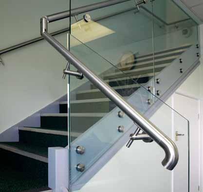
Innovative Handrail Solutions New Possibilities TESTED TO BS6180 FREE FIXINGS SUPERIOR CORROSION RESISTANCE WITH G316‘s’ Fast-Track® Channel System Kwik-Lock® Dialed In Adjustment Kwik-Lock® MAX Introducing... 40% RECYCLED ALUMINIUM
Fastec Handrail Systems
Innovative Handrail Solutions
about us

Fastec Handrail Systems specialises in the supply and delivery of off-the-shelf modular handrail systems.
We have designed and manufactured our Fastec modular handrail systems to fulfil all your requirements.
Fastec Handrail Systems forms part of the Barrett Steel Ltd group. We operate from a purpose-designed 3100ft2 warehouse and sales facility and hold extensive stocks within the UK, ensuring rapid next-day turnaround to service and meet all your requirements.
Our friendly sales advisors are here to help, offering sales assistance and technical support to ensure you receive the best levels of service and aftercare.
Fastec has established a reputation for outstanding customer service, total reliability, fast delivery and above all, premium quality products.
All our products are available off the shelf, ready for next-day delivery wherever you are in the UK. We will help you stay within your project’s budget without compromising on quality, service or the aesthetic appearance of your completed installation.
And for your complete peace of mind, our products have been independently tested for safety.
philosophy
Creativity. Innovation. Technical Mastery
These are Fastec Handrail Systems watchwords. We are a progressive business, working in long-term partnerships with our customers to realise your project’s full aesthetic and functional potential.
You can be sure we understand your business and the environment in which you operate. Our customers choose us because they know they can rely on our innovative approach and complete commitment to the success of a project.
We’ll work closely with you to ensure your budgets and timescales are met sharing our judgement, expertise and problem solving skills to guarantee the best outcome for your project and your business.
We focus on your requirements because the end result is as important to us as it is to you. That’s why we add value every step of the way whilst keeping you on schedule and within budget. We’re more than happy to have a no-obligation discussion with you about your current and future plans.
3
Fastec Handrail Systems

2010 Page 23
1010 Page 17
1020 Page 19
2020 Page 27
0125/0150 Page 8
9510 Page 32
1205 Page 70
0250 Page 34
3010 Page 31
7200 Page 45
4000 Page 115
5010 Page 53
4100 Page 118
0525 Page 77
0150 Page 68
0155 Page 68
1050 Page 87
0160 Page 87
3900 Page 111
0645 Page 79
1105 Page 89
0735 Page 82
0135 Page 67
8010 Page 57
4 5
Model:
Model:
Model:
Model:
Model: 0150 Page 83
Model: 1150 Page 89
Model:
Model:
Model:
Model:
Model:
Model:
Model:
Model: 0157 Page 68
Model:
Model:
Model:
Model:
Model:
Model:
Model:
Model:
Model:
Model:
Model:
Model:
Model: 0745 Page 83
Model:
Fastec Handrail Systems Fastec Handrail Systems
Model: 9400 PAGE 131
Glass-Tec Tubes and bars
r ailin G s ys T ems
Glass a
a ccessories
Technical 12-50 60-127 52-59 128-129 134-157 130-133
s Pi G o T s
lu-rail
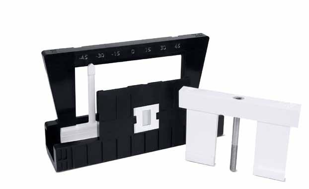
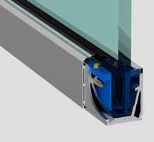
Kwik-Lock®


DIALLED IN ADJUSTEMNT
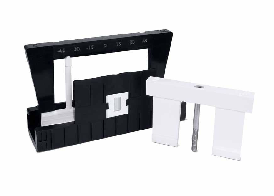
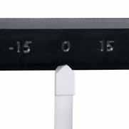
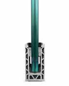
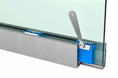
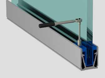
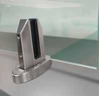
Only the Kwik-Lock system has a dial and gauge for ease of adjustment. This innovative idea helps adjust and align the glass perfectly by transferring the location of the slider at the bottom onto the gauge at the top. After one panel has been installed simply pre-set the gauges on your next panel identically to ensure an exact alignment every time.
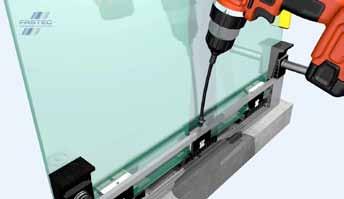
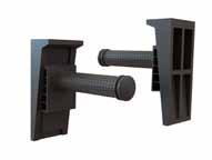
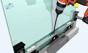
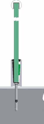
MECHANICAL FIXING
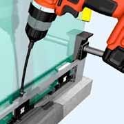
Securing the Kwik-Lock wedge couldn’t be easier, simply tighten the bolt. This action pulls the wedge down into the channel and naturally tightens up when the wedge finds its resting location. mechanical tightening provides a more secure fixing and prevents wedge movement at a later date by applying a consistent toque onto the wedge. To speed things up use a battery drill and torque setting to hear a satisfying click as the torque is reached.
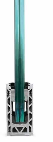
TWIN LOCKING SYSTEM
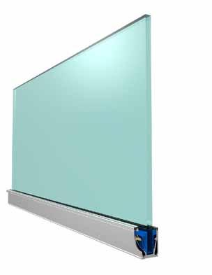
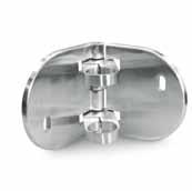
The Kwik-Lock system uses two separate fixing methods to provide a safe and secure glass fixing and peace of mind that only having a secondary fixing with multiple touch points can offer. The wedge locks the glass into position when the bolt is tightened, a secondary Pull Out Block works with the mechanics of tightening the bolts sliding out securing the glass providing a movement free installation.
CLICK IN SYSTEM
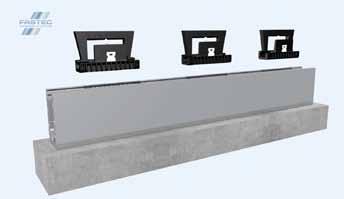
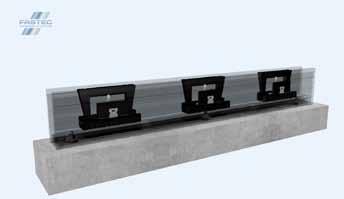
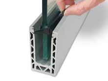
There’s nothing more satisfying than hearing a ‘CLICK’ when something snaps into place. With the unique locking system integrated into the Fast-Track channel and Kwik-Lock wedges the two are made for each other. Push the Kwik-Lock wedges into the channel and hear the click knowing its placed correctly.
technical innovationmastery creativity
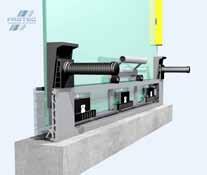
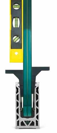
ONE SIDED INSTALLATION
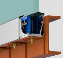
Every element of the Fast-Track channel system has been created with practicality and safety in mind. Not only does it look great but has the added benefit of installation from one side, eliminating the need to hire costly scaffolding or lifting equipment and more importantly, installers can work much more safely. These practical and crucial innovations save both time and money making every project more efficient and cost effective.
9
Introducing... 8
Mechanical Fixing Twin Locking System Click in System One
Dialled in Adjustment
Sided Installation
Dialed
In Adjustment
The revolutionary glass adjustment system Patent Application No. 1714477.5

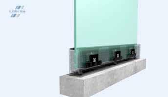
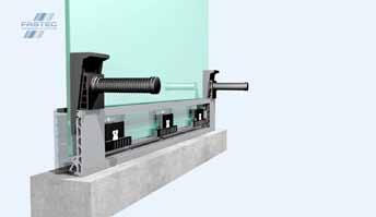
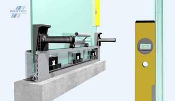
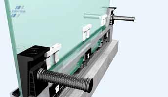
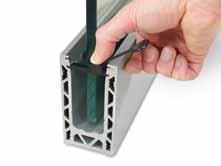
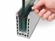
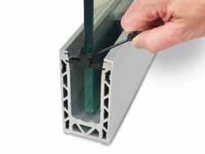
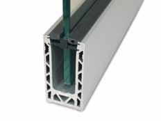
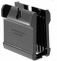
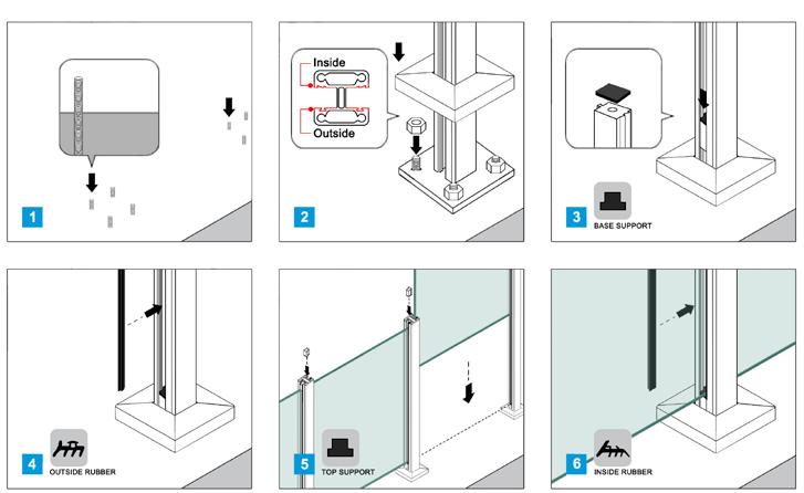
10 11 KWICK-LOCK USEr GUidE KWICK-LOCK USEr GUidE Your complete guide to using the Kwik-Lock system workworkquicker,smarter, work Kwik-Lock Easy as one, two, three 1. Place retainers into track 2. Slide retainers into position 7 insert wedges 8 Tighten wedge bolt to lock into possition 5. Pin glass in place with placement tools 6. Adjust slider using adjustment tool to tilt glass 3. insert rear side rubber seal strip 4 Place glass into possition 9 insert front rubber seal strip 10 installation complete Kwik-Lock® Dialed In Adjustment Patent Application No. 1714477.5 www.fastechandrails.co.uk www.fastechandrails.co.uk
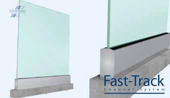
Fast-Track®
Fas T -Track h andrail & F i TT in G s Posi G laze al u-rail s P i G o T s & Glass 14-15 LOAD TABLES 16-17 M ODEL 1010 18-20 M ODEL 1020 22-24 M ODEL 2010 26-28 M ODEL 2020 30-31 M ODEL 3010 32 TOOLS 33 P I n S A n D BOLT S 53 G LASS S PIGOTS 55 G LASS 36-37 TOP F I x 38 P OSIGLA z E B LA c K 40-42 S IDE FI x 43 M EGAG r IP 45 ‘U’ Pr OFILE 46-47 rOU n D Pr OFILE 48 rE c TA n GULA r Pr OFILE 49-50 rOU n D M I rr O r 56-59 A LU -r AIL
c hannel System
Dialed In Adjustment
Kwik-Lock®
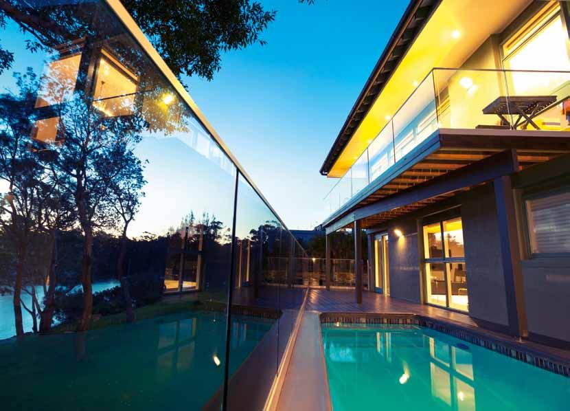
safety first solutions for every space
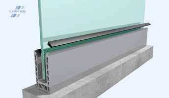
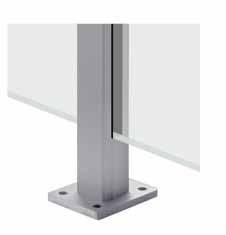
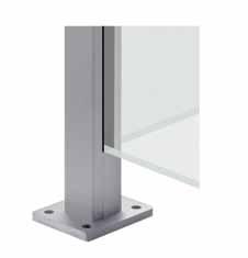
For individual installations of glass balustrades you can choose between base or side fixed profiles. The construction you attach the balustrade to plays an important role in the choice of system, and whether a side mount or a top mount profile is required.
The following pages show you our range of products. All the systems are modular, which means you can assemble your own selection of products to fulfil your project designs easily and conveniently.
Glass balustrades must meet the requirements of British Standards. The Glass-tec profiles have been independently tested to ensure the safety of your installation.
Please refer to the chart, so you can see at a glance which systems can be used in your construction project.


Kwik-Lock
15 14 Please refer to Table 2 of BS6180 for full details/clarification on imposed loads.
* Full test data can be provided on request.
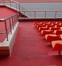
relatively light constructions can be designed for applications in homes. The glass balustrade must be able to withstand 0.36 kN per linear metre. Kwik-Lock Glass balustrades used for external housing and offices require thicker glass. The glass balustrade must be able to withstand 0.74 kN per linear metre. Kwik-Lock The extensive use associated with public spaces requires the use of heavier materials to guarantee safety. The glass balustrade must be able to withstand 1.5 kN per linear metre. Kwik-Lock MAX Stadium criteria requires the most robust solutions. Glass thickness even for heavy loads. The glass balustrade must be able to withstand 3.0 kN per linear metre. Achieved Glass Thickness Achieved Glass Thickness Achieved Glass Thickness Achieved Glass Thickness mm mm mm mm mm mm mm 12 13.52 15 17.52 21.52 25.52 600 600 600 600 400 200 12 13.52 15 17.52 21.52 25.52 600 600 600 600 200 200 12 13.52 15 17.52 21.52 25.52 400 400 400 400 200 200 12 13.52 15 17.52 21.52 25.52 400 400 600 600 200 200 12 13.52 15 17.52 ✗ ✗ 600 600 600 600 15 19 21.52 ✗ 200 200 200 15 19 21.52 ✗ ✗ 200 200 200 25, 25.52, 31.52, 33 200 INTErNAL HOUSiNG 0.36KN EXTErNAL HOUSiNG 0.74KN OFFICE FUNcTiON 0.74KN PUBLIC ArEAS 1.5KN STADIUM FUNcTiON 3.0KN Model Test House Mount Type Page 16 1010 JAMES FiSHEr Top Mount Bolt c entres Page 18 1020 JAMES FiSHEr Side Mount Bolt c entres Page 22 2010 JAMES FiSHEr Top Mount Bolt c entres Page 26 2020 JAMES FiSHEr Side Mount Bolt c entres Page 30 3010 JAMES FiSHEr Top Mount Bolt c entres Page 36 Posi-glaze SANdBErG Top Mount Bolt c entres Page 40 Posi-glaze SANdBErG Side Mount Bolt c entres Page 43 Megagrip LUcidEON Top Mount Bolt c entres TesTed bs6180 to Fastec Handrail Systems Fastec Handrail Systems

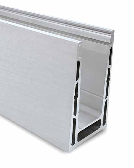
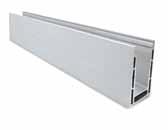
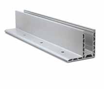
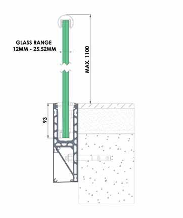
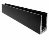
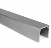
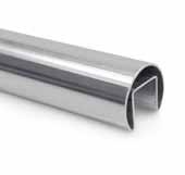
16 17 FAST-TrAcK MODEL 1010 | 0.36-3KN Fast
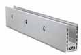
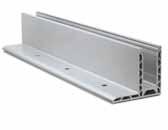
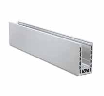
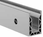
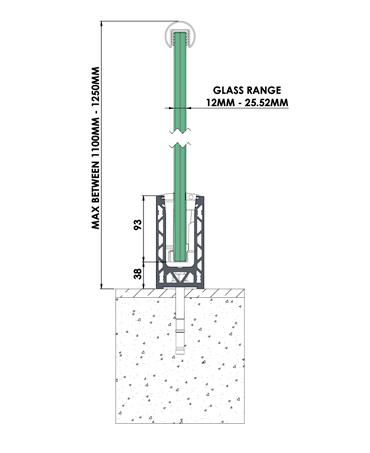
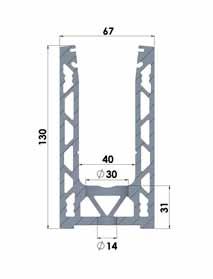
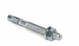
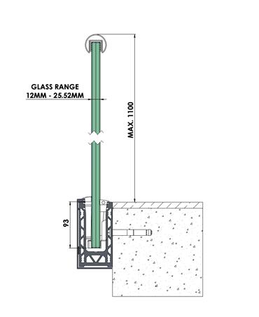
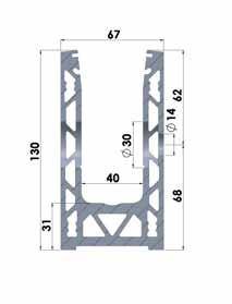
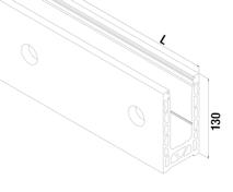
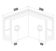
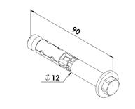
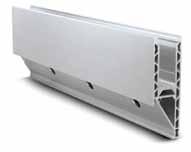
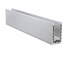
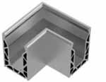
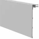
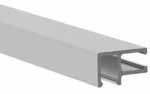
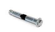
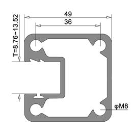
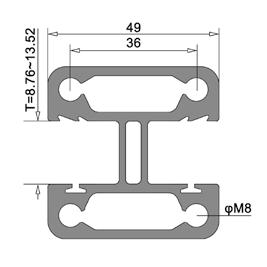
• Brushed Anodised finish • Upto 600mm bolt centres • Water drainage holes • Glass thickness range 12-25.52mm • Joining Pins • Manufactured with Recycled Aluminium MOdEL 1010 0.36-3kN TOP MOUNT Model 1010 Profile Aluminium Outdoor cOdE L 11.1010.025.A 2500 1 11.1010.050.A 5000 1 Model 1010 Inside/Outside Corner Aluminium Outdoor cOdE 11.1010.200.A 1 Model 1010 End Cap Aluminium Outdoor cOdE 11.1010.300.A 1 Model 1010 End Cap for Stairs Aluminium Outdoor cOdE 11.1010.301.A 1 See page 146 for mounting instructions Model 0125/0150 1.5kN Kwik-Lock Outdoor cOdE USE kN GLASS L 50.0125.012.W 0.36 12 2500 1 50.0125.013.W 0.36 13.52 2500 1 50.0125.015.W 0.74 15 2500 1 50.0125.017.W 0.74 17.52 2500 1 50.0125.021.W 1.5 21.52 2500 1 50.0150.012.W 0.36 12 5000 1 50.0150.013.W 0.36 13.52 5000 1 50.0150.015.W 0.74 15 5000 1 50.0150.017.W 0.74 17.52 5000 1 50.0150.021.W 1.5 21.52 5000 1 Model 0250 3kN Kwik-Lock MAX Outdoor cOdE USE kN GLASS L 50.0250.025.W 3.0 25.52 5000 1 Model 7001 Extension Pin G316 Outdoor cOdE 36.9201.406. r 8 Model 9512 Mounting Anchor Zintec Outdoor cOdE 20.9512.120.Z 20 TesTed bs6180 to 0.36kN 600mm Ctrs 0.74kN 600mm Ctrs 1.5kN 400mm Ctrs 3kN 200mm Ctrs 40% RECYCLED ALUMINIUM See Page 21 www.fastechandrails.co.uk www.fastechandrails.co.uk
-Track®

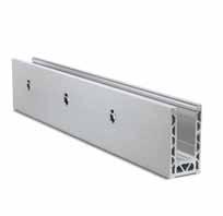
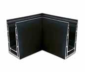
18 19 FAST-TrAcK MODEL 1020 | 0.36-3KN
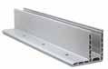
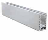
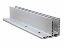
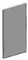
• Brushed Anodised finish • Upto 600mm bolt centres • Water drainage holes • Glass thickness range 12-25.52mm • Joining Pins • Manufactured with Recycled Aluminium MOdEL 1020 0.36-3kN SidE MOUNT Model 1020 Glass Profile Aluminium Outdoor cOdE L 11.1020.025.A 2500 1 11.1020.050.A 5000 1 Model 1020 Inside Corner Aluminium Outdoor cOdE 11.1020.210.A 1 Model 1020 Outside Corner Aluminium Outdoor cOdE 11.1020.250.A 1 Model 1020 End Cap Aluminium Outdoor cOdE 11.1020.300.A 1 Model 1020 End Cap for cladding Aluminium Outdoor cOdE HANd 11.1020.305.A Left 1 11.1020.315.A r ight 1 Model 1020 End Cap for stairs Aluminium Outdoor cOdE 11.1020.301.A 1 Model 1020 End Cap for Stairs & Cladding Aluminium Outdoor cOdE HANd 11.1020.306.A Left 1 11.1020.316.A r ight 1 Model 1020 Cladding Aluminium Outdoor cOdE L 11.1020.125.A 2500 1 11.1020.150.A 5000 1 See page 147 for mounting instructions 0.36kN 600mm Ctrs 0.74kN 600mm Ctrs 1.5kN 200mm Ctrs 3kN 200mm Ctrs TesTed bs6180 to 40% RECYCLED ALUMINIUM See Page 21 www.fastechandrails.co.uk www.fastechandrails.co.uk
Fast-Track®

Helping your project meet the demands of Sustainable Construction
All Fast-Track system profiles are manufactured from an average of 36-40% recycled aluminium, if a project requires a more specific higher requirement, then this can be reviewed and discussed on a case-by-case basis.
recycling is a critical part of the modern aluminium business. As one of the most recycled—and recyclable—materials in use today the process involves simply re-melting the metal, which is far less expensive and energy-intensive than creating new aluminium. A recycled aluminium window frame, door or drinks can is often recycled directly back into itself for a more circular and sustainable economy.
Environmental Benefits
Recycling aluminium uses 95% less energy than producing primary aluminium. Saves 97% of greenhouse gas emissions produced in primary production process.
50.0150.012.W
Recycling 1 tonne of aluminium saves 9 tonnes of CO2 emissions (1 tonne of CO2 is equivalent to driving over 3,500 miles).
Recycling 1 tonne of aluminium saves 4 tonnes of bauxite – the raw material from which aluminium is made.
Aluminium is 100 per cent recyclable, so carbon savings increase every time it passes through the recycling loop.
Aluminium is an infinitely recyclable material.
Nearly 75% of all aluminium ever produced is still in use today.
Fast-Track®
c hannel System
20 21 FAST-TrAcK MODEL 1020 | 0.36-3KN Model 9612 Mounting Anchor Zintec Outdoor cOdE 20.9612.090.Z 20 Model 7001 Extension Pin G316 Outdoor cOdE 36.9201.406. r 8 Model 0250 3kN Kwik-Lock MAX Outdoor cOdE USE kN GLASS L 50.0250.025.W 3.0 25.52 5000 1 Model 0125/0150 1.5kN Kwik-Lock Outdoor cOdE USE kN GLASS L 50.0125.012.W 0.36 12 2500 1 50.0125.013.W 0.36 13.52 2500 1 50.0125.015.W 0.74 15 2500 1 50.0125.017.W 0.74 17.52 2500 1 50.0125.021.W 1.5 21.52 2500 1
0.36 12 5000 1 50.0150.013.W 0.36 13.52 5000 1 50.0150.015.W 0.74 15 5000 1 50.0150.017.W 0.74 17.52 5000 1 50.0150.021.W 1.5 21.52 5000 1
www.fastechandrails.co.uk www.fastechandrails.co.uk
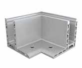
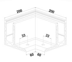
22 23 FAST-TrAcK MODEL 2010 | 0.36-3KN Model 2010 Inside Corner Aluminium Outdoor cOdE 11.2010.210.A 1 Model 2010 Outside Corner Aluminium Outdoor cOdE 11.2010.250.A 1
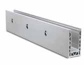
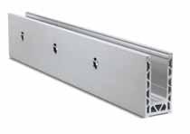
• Brushed Anodised finish • Upto 600mm bolt centres • Water drainage holes • Glass thickness range 12-25.52mm • Joining Pins • Manufactured with Recycled Aluminium MOdEL 2010 0.36-3kN TOP MOUNT See page 148 for mounting instructions Model 2010 Profile Aluminium Outdoor cOdE L 11.2010.025.A 2500 1 11.2010.050.A 5000 1 Model 2010 End Cap Aluminium Outdoor cOdE HANd 11.2010.300.A Left 1 11.2010.310.A r ight 1 Model 7001 Extension Pin G316 Outdoor cOdE 36.9201.406. r 8 TesTed bs6180 to 0.36kN 400mm Ctrs 0.74kN 400mm Ctrs 1.5kN 200mm Ctrs 3kN 200mm Ctrs 40% RECYCLED ALUMINIUM See Page 21 www.fastechandrails.co.uk www.fastechandrails.co.uk
Fast-Track®
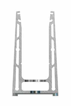
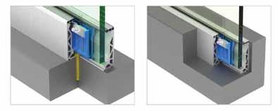
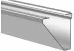
Dr AInAGE SOLUTIOnS
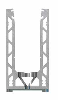
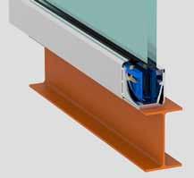
Integral Drainage Solution
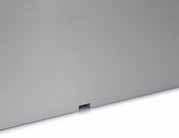
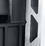
Using the Fast-Track base systems has never been easier as we have included a drainage solution on each profile design. This solution allows water that can potentially seep inside of the channel to drain away preventing pooling of water. The same integral system on the Model 1010 top fix channel allows the outer faces to be filed away to prevent build-up of water on the outside caused by the fall on the floor allowing the water to pass through.
24 25 FAST-TrAcK MODEL 2010 | 0.36-3KN Model 9512 Mounting Anchor Zintec Outdoor cOdE 20.9512.120.Z 20 Model 0250 3kN Kwik-Lock MAX Outdoor cOdE USE kN GLASS L 50.0250.025.W 3.0 25.52 5000 1 Model 0125/0150 1.5kN Kwik-Lock Outdoor cOdE USE kN GLASS L 50.0125.012.W 0.36 12 2500 1 50.0125.013.W 0.36 13.52 2500 1 50.0125.015.W 0.74 15 2500 1 50.0125.017.W 0.74 17.52 2500 1 50.0125.021.W 1.5 21.52 2500 1 50.0150.012.W 0.36 12 5000 1
0.36 13.52 5000 1
0.74 15 5000 1 50.0150.017.W 0.74 17.52 5000 1 50.0150.021.W 1.5 21.52 5000 1
50.0150.013.W
50.0150.015.W
Model 2010
Model 1010
Model 3010
Model 1020
Model 2020
www.fastechandrails.co.uk www.fastechandrails.co.uk
26 27 FAST-TrAcK MODEL 2020 | 0.36-3KN
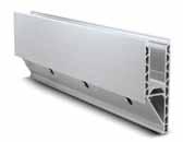
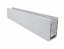
• Brushed Anodised finish • Upto 600mm bolt centres • Water drainage holes • Glass thickness range 12-25.52mm • Joining Pins • Manufactured with Recycled Aluminium MOdEL 2020 0.36-3kN SidE MOUNT See page 149 for mounting instructions Model 2020 Glass Profile Aluminium Outdoor cOdE L 11.2020.025.A 2500 1 11.2020.050.A 5000 1 Model 2020 Inside Corner Aluminium Outdoor cOdE 11.2020.210.A 1 Model 1020 Outside Corner Aluminium Outdoor cOdE 11.2020.250.A 1 Model 2020 End Cap Aluminium Outdoor cOdE HANd 11.2020.300.A Left 1 11.2020.310.A r ight 1 Model 2020 Cladding Aluminium Outdoor cOdE L 11.2020.125.A 2500 1 11.2020.150.A 5000 1 Model 7001 Extension Pin G316 Outdoor cOdE 36.9201.406. r 8 TesTed bs6180 to 0.36kN 400mm Ctrs 0.74kN 600mm Ctrs 1.5kN 200mm Ctrs 3kN 200mm Ctrs 40% RECYCLED ALUMINIUM See Page 21 www.fastechandrails.co.uk www.fastechandrails.co.uk
Fast-Track®
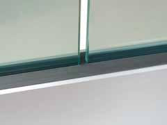
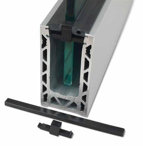
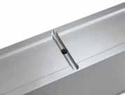
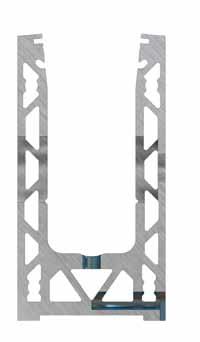
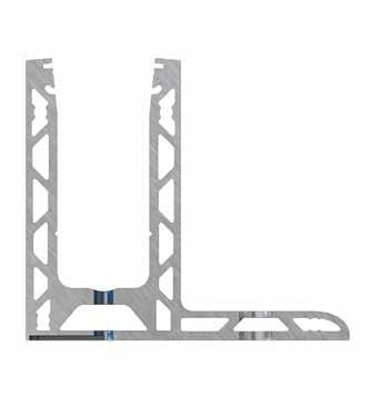
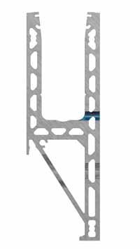
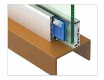
the why
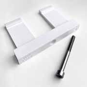
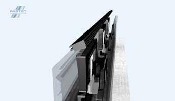
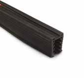
With most glazing systems using rubber seals running parallel with the glass creates a gap between adjoining glass panels. This gap it not only unsightly and makes the installation look unfinished but also allows water penetration into the channel.
the
what
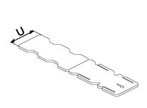
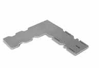
Fastec have designed and introduced Link Connectors within the Kwik-Lock fixing kits. These creative connectors easily and permanently fill the gap between adjoining panels.
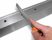
the how
insert and click the link connector into the recesses within the base channel, slide the block to the middle, cut the required length of gasket to size and stick into position.
28 29 FAST-TrAcK MODEL 2020 | 0.36-3KN Model 0125/0150 1.5kN Kwik-Lock Outdoor cOdE USE kN GLASS L 50.0125.012.W 0.36 12 2500 1 50.0125.013.W 0.36 13.52 2500 1 50.0125.015.W 0.74 15 2500 1 50.0125.017.W 0.74 17.52 2500 1 50.0125.021.W 1.5 21.52 2500 1 50.0150.012.W 0.36 12 5000 1 50.0150.013.W 0.36 13.52 5000 1 50.0150.015.W 0.74 15 5000 1 50.0150.017.W 0.74 17.52 5000 1 50.0150.021.W 1.5 21.52 5000 1 Bridging the gap between balustrade and glass what,why,how Link Connectors
Model 9512 Mounting Anchor Zintec Outdoor cOdE 20.9512.120.Z 20 Model 0250 3kN Kwik-Lock MAX Outdoor cOdE USE kN GLASS L 50.0250.025.W 3.0 25.52 5000 1 www.fastechandrails.co.uk www.fastechandrails.co.uk
Fast-Track®

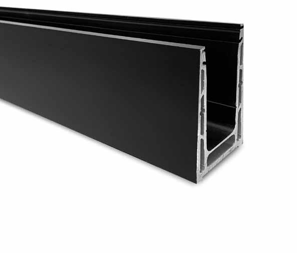
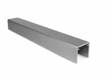
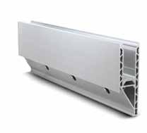
30 31 FAST-TrAcK MODEL 3010 | 0.74KN
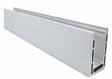
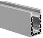
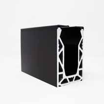
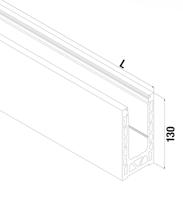
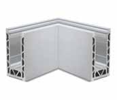
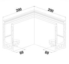
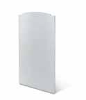
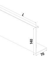
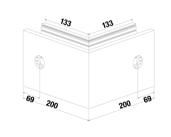
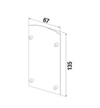
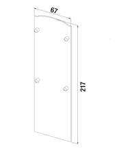
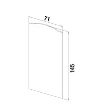
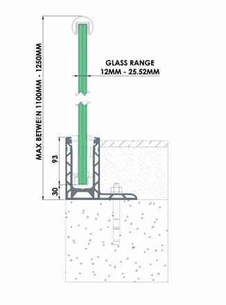
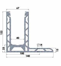
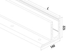
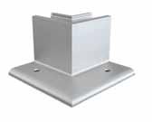
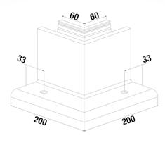
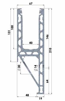
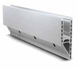
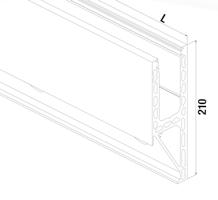
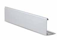
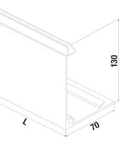
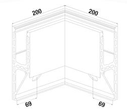
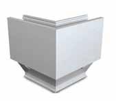
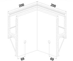
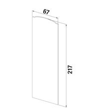
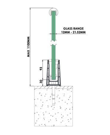
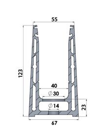
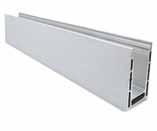
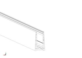
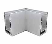
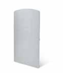
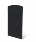
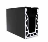
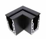
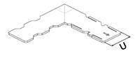
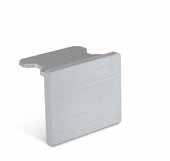
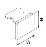
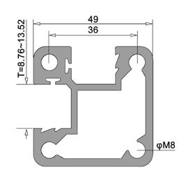
• Brushed Silver Anodised finish • Black Anodised finish • Upto 600mm bolt centres • Water drainage holes • Glass thickness range 12-21.52mm • Joining Pins • Manufactured with Recycled Aluminium MOdEL 3010 0.74kN TOP MOUNT 200 200 200 200 L 123 L 123 Model 3010 Profile Aluminium Outdoor cOdE L 11.3010.025.A 2500 1 11.3010.050.A 5000 1 Model 3010 Profile Aluminium Outdoor cOdE L 11.3010.025.BK 2500 1 11.3010.050.BK 5000 1 Model 3010 Inside/Outside Corner Aluminium Outdoor cOdE 11.3010.200.A 1 Model 3010 Inside/Outside Corner Aluminium Outdoor cOdE 11.3010.200.BK 1 128 55 67 Model 3010 End Cap Aluminium Outdoor cOdE 11.3010.300.A 1 128 55 67 Model 3010 End Cap Aluminium Outdoor cOdE 11.3010.300.BK 1 See page 150 for mounting instructions Model 0125/0150 1.5kN Kwik-Lock Outdoor cOdE USE kN GLASS L 50.0125.012.W 0.36 12 2500 1 50.0125.013.W 0.36 13.52 2500 1 50.0125.015.W 0.74 15 2500 1 50.0125.017.W 0.74 17.52 2500 1 50.0125.021.W 1.5 21.52 2500 1 50.0150.012.W 0.36 12 5000 1 50.0150.013.W 0.36 13.52 5000 1 50.0150.015.W 0.74 15 5000 1 50.0150.017.W 0.74 17.52 5000 1 50.0150.021.W 1.5 21.52 5000 1 Model 7001 Extension Pin G316 Outdoor cOdE 36.9201.406. r 8 Model 9512 Mounting Anchor Zintec Outdoor cOdE 20.9512.120.Z 20 TesTed bs6180 to 0.36kN 600mm Ctrs 0.74kN 600mm Ctrs 40% RECYCLED ALUMINIUM See Page 21 www.fastechandrails.co.uk www.fastechandrails.co.uk
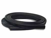
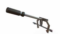
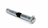
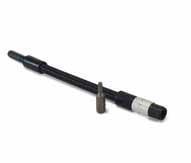
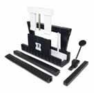
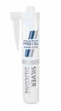
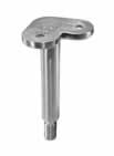
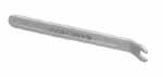
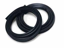
32 33 TOOLS/ACCESSOrIES TOOLS/ACCESSOrIES Model 9500 Tool Kit cOdE 10.9500.000.T 1 Model 9504 Adjustment Tool cOdE 10.9504.000.T 1 Model 9505 Placement Blocks cOdE 10.9505.000.T 2 Model 9507 Flex Extension c/w Hex Bit cOdE 10.9507.000.T 1 Model 9506 Wedge removal Tool cOdE 10.9506.000.T 1 Model 9510 Silver Silicone cOdE 10.9510.000.T 1 Model 7001 Extension Pin G316 Outdoor cOdE 36.9201.406. r 8 Model 0150 replacement Seal Strips rubber Indoor cOdE L G 40.0150.012. r 5000 12 2 40.0150.013. r 5000 13.52 2 40.0150.015. r 5000 15 2 40.0150.017. r 5000 17.52 2 40.0150.021. r 5000 21.52 2 Model 9512 Mounting Anchor Zintec Outdoor cOdE 20.9512.120.Z 20 Model 9612 Mounting Anchor Zintec Outdoor cOdE 20.9612.090.Z 20 INFO www.fastechandrails.co.uk www.fastechandrails.co.uk
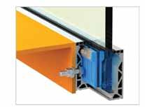
KWIK-LOCK MAX ACHIEVES 3.0KN WITH 25.52MM GLASS
Having experience in the cost, weight and difficulties of handling 31.52mm glass that many other systems use to achieve 3.0kN loadings we were determined to be a class leader and reduce this to 25.52mm. All Fast-Track
Kwik-Lock MAX achieves 3.0KN with 25.52mm glass offering all the benefits of cost and time savings associated with working with thinner glass whilst providing a more minimalistic appearance.
SIMPLE ADJUSTABILITY
system includes the ability to tilt and align the glass panels easily by simply moving the placement wedges higher or lower within the top of the channel by hand. This action allows the glass to tilt forwards or backwards. This top adjustment removes the difficulties of adjusting the heavier glass thicknesses at the bottom due to the increased weights and friction incurred making the lower mechanical adjustment restrictive.


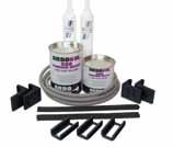
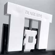
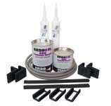
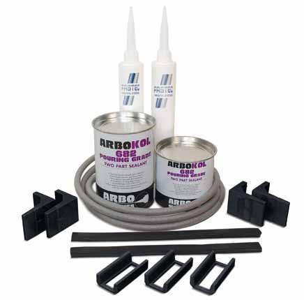
uses a combination of both lower glass holders and a thin top layer of Arbokol Balustrade Sealant to secure the glass into position. This dual system ensures maximum strength and versatility for securing the glass when higher side loadings are required..
DrY FIX AND ALIGN MULTIPLE PANELS
With the unique dual fixing system which is utilised with the Kwik-Lock Max to align and support the glass in position until the Balustrade sealant has been laid, means that a full row or multiple panels of glass can be dry fixed and secured in place ensuring full alignment and easy adjustment until the installer is happy to add the sealant to permanently secure the glass in position.
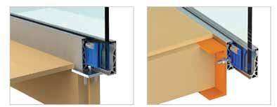
ONE PrOFILE, ONE DESIGN, ONE PrICE FOr ALL INSTALLATIONS
Having the confidence to install the same profile in any situation was a major factor in our thinking when designing the Fast-Track range. We wanted a single solution that would be elegant enough for the smallest project but robust enough to comply with the largest loading criteria when needed. Our profiles are utilised with either the Kwik-Lock or Kwik-Lock Max wedge kits to meet all your installation requirements.
Introducing...
Kwik-Lock® MAX
3.0kN with 25.52mm Glass
Simple Adjustability
Semi Wet Fix System
Dry Fix and Align
One Profile, One Design, One Price
34 35
For Maximum Strength strengthperformance power 25.52mm

36 37 POSI-GLAZE | 1.5KN TOP MOUNT 112 120 72 120
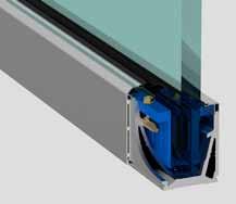
• Slender, attractive design and low maintenance • Fast and easy glass adjustment • Extension pin ducts • Can be clad both sides • Glass thickness range 12-21.52mm POSi-GLAZE 1.5kN TOP MOUNT in door: 91 3511 015 81 outdoor: 91 3511 015 30 (15x/3 mtr) 1 1 0 0 max. 10/10/4 (21.52mm) 2 6 9 4 72 ø28 112 93 ø15 18 aPProVed bs6180 according to See page 154 for mounting instructions Model PGA Corner Aluminium Outdoor cOdE L PGA-090 136 1 80 85 Model PGB Clamp kit cOdE GLASS L PGB-0012 12 3000 1 PGB-0013 13.5 3000 1 PGB-0015 15 3000 1 PGB-0017 17.5 3000 1 PGB-0019 19 3000 1 PGB-0021 21.5 3000 1 30 9 Model PGA Spanner Steel cOdE PGA-050 1 Model PGA Extension pin AISI 316 Outdoor cOdE PGA-070 1 Model PGC Glass profile Aluminium Outdoor cOdE L PG c -010 3000 1 Model PGA Side Cladding Aluminium Outdoor cOdE L PGA-010 3000 1 Model PGA Top seal strip Aluminium Outdoor cOdE L PGA-030 3000 1 (2 No. required as per drawing page 36) Model PGA End Cap Aluminium Outdoor cOdE PGA-060 1 Model 9612 Mounting Anchor Zintec Outdoor cOdE 20.9612.090.Z 20 www.fastechandrails.co.uk www.fastechandrails.co.uk
Glass-tec
The first fully adjustable balustrade system
FAST AND EASY TO INSTALL AND ADJUST
One of the most simple balustrade systems to fit and adjust thanks to its patented screw-clamp technology. dry glaxed where no specialist tools are required. Glass can easily be removed and replaced if required.
ACCrEDITED TO 1.50kN TO BS 6180:2011
POSIglaze is accredited and approved by multiple organisations to verify that it meets national and international building regulations for use as edge protection, where up to 1.50kN force loading is required.
IGHTWEIGHT AND STrONG
Precision engineered using extruded aluminum with a geometrically hollowed out core; providing an incredible strenght to weight ratio. For added protection POSIglaze is anodised to 25 microns.
APPrOPrIATE FOr DOMESTIC AND COMMErCIAL
With 0.36kN to 1.50kN force loading capability, POSIglaze is a domestic to light commercial crossover product, making it an appropriate choice for a wide range of installations.
CAN BE USED WITH A WIDE rANGE OF GLASS TYPES
POSIglaze is a highly versatile product which can be used with glass thicknesses ranging from 12mm - 21.5mm, using either toughened glass, toughened laminate glass or SentryGlas.
SUITABLE FOr USE ON UNEVEN SUrFACES
POSIglaze is a highly versatile product which can be used with glass thicknesses ranging from 12mm - 21.5mm, using either toughened glass, toughened laminate glass or SentryGlas.
38 39 POSI-GLAZE | 1.5KN TOP MOUNT BLACK 112 72 120 Model PGA Corner Aluminium Outdoor cOdE L PGA-090BK 136 1 Model PGC Glass Profile Aluminium Outdoor cOdE L PG c -010BK 3000 1 Model PGA Top Seal Strip Plastic Outdoor cOdE L PGA-030P 3000 1 (2 No. required as per drawing page 46) Model PGA End Cap Plastic Outdoor cOdE PGA-060PBK 1 80 85 Model PGB Clamp Kit cOdE GLASS L PGB-0012 12 3000 1 PGB-0013 13.5 3000 1 PGB-0015 15 3000 1 PGB-0017 17.5 3000 1 PGB-0019 19 3000 1 PGB-0021 21.5 3000 1 30 9 Model PGA Spanner Steel cOdE PGA-050 1 Model PVA Touch Up Pen Steel cOdE PVA-TOU c HBK 1 Model PGA Extension pin AISI 316 Outdoor cOdE PGA-070 1 Model 9612 Mounting Anchor Zintec Outdoor cOdE 20.9612.090.Z 20
www.fastechandrails.co.uk www.fastechandrails.co.uk
• Slender, attractive design and low maintenance
• Fast and easy glass adjustment
• Extension pin ducts
• Side and bottom cladding available
• Glass thickness range 12-21.52mm
40 41 POSI-GLAZE | 0.74KN SidE MOUNT 120 112 72 120
Glass-tec
POSi-GLAZE 0.74kN SidE
ndoor: 91 3511 015 81 outdoo : 91 3511 015 30 (15x/3 mtr) 1 1 0 0 max. 10/10/4 (21.52mm) 9 4 2 6 ø 15 ø 28 72 112 93 57 ndoor: 91 3511 015 81 outdoor: 91 3511.015.30 (15x/3 mtr) 1 1 0 0 max. 10/10/4 (21.52mm) 9 4 2 6 ø 15 ø 28 72 112 93 57 aPProVed bs6180 according to 72 182 62 See page 154 for mounting instructions Model PGC Glass Profile Aluminium Outdoor cOdE L PG c -020 3000 1 Model PGA Bottom Cladding Aluminium Outdoor cOdE L PGA-020 3000 1 Model PGA End Cap Aluminium Outdoor cOdE PGA-061 One Side c ladding 1 PGA-062 Two Side c ladding 1 Model PGA End Cap Aluminium Outdoor cOdE PGA-065 r 1 PGA-065L 1 Model PGA Top Seal Strip Aluminium Outdoor cOdE L PGA-030 3000 1 Model PGA Side Cladding Aluminium Outdoor cOdE L PGA-010 3000 1 www.fastechandrails.co.uk www.fastechandrails.co.uk
MOUNT
megaGrip
Commercial Frameless Balaustade
Need a 3kN system? Then megaGrip is for you!

Using 25mm glass megaGrip meets 3kN loadings in a number of scenarios. •
42 43 POSI-GLAZE | 0.74KN SidE MOUNT
3kN Loading
Simple to install
No specialised tools • Durable adonised finish
panel of glass can be fully adjusted after installation of the channel. 80 85 30 9 80 85
•
•
Each
Commercial Frameless Balaustade Fully Adjustable Model PGA Spanner Steel cOdE PGA-050 1 Model PGA Extension Pin AISI 316 Outdoor cOdE PGA-070 1 Model PGB Clamp Kit cOdE GLASS L PGB-0012 12 3000 1 PGB-0013 13.5 3000 1 PGB-0015 15 3000 1 PGB-0017 17.5 3000 1 PGB-0019 19 3000 1 PGB-0021 21.5 3000 1 Model PGB Top Seal rubbers cOdE GLASS L PGB-0012 12 3000 1 PGB-0013 13.5 3000 1 PGB-0015 15 3000 1 PGB-0017 17.5 3000 1 PGB-0019 19 3000 1 PGB-0021 21.5 3000 1 Model 9612 Mounting Anchor Zintec Outdoor cOdE 20.9612.090.Z 20 www.fastechandrails.co.uk www.fastechandrails.co.uk
megaGrip


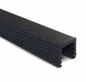
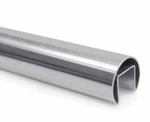
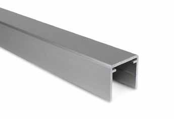
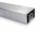
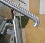
45 HANDrAIL/FITTINGS Model 7200 U-Handrail Aluminium Outdoor cOdE U H L 11.7200.027.A 27 23 4000 1 11.7200.031.A 31 29 4000 1 Model 7220 U-Connector G304 Outdoor cOdE U 11.7220.027. r 27 1 11.7220.031. r 31 1 Model 7225 U-Corner Connector G304 Outdoor cOdE U 11.7225.027. r 27 1 11.7225.031. r 31 1 Model 7270 U-End Cap Aluminium Outdoor cOdE U H 11.7270.027.A 27 23 1 11.7270.031.A 31 29 1 Model 7027 U-Handrail rubber rubber Outdoor cOdE L U G 40.7027.010. r 4000 27 10-13.52 1 40.7027.015. r 4000 27 15-17.52 1 40.7031.015. r 4000 31 15-17.52 1 40.7031.019. r 4000 31 19-21.52 1 2 U 4000 4000 H U GLASS HANDRAILS www.fastechandrails.co.uk

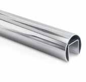
46 47 HANDrAIL/FITTINGS HANDrAIL/FITTINGS 0-60º Downwards 25-60º Upwards Model 7000/7100 Handrail 304 Indoor cOdE L ø T U 34.7000.420.S 5000 42.4 24 24 1 34.7000.480.S 5000 48.3 30 27 1 34.7000.600.S 5000 60.3 34 34 1 34.7100.420.S 2500 42.4 24 24 1 34.7100.420.S 2500 48.3 30 27 1 34.7100.600.S 2500 60.3 34 34 1 Model 7000/7100 Handrail 316 Outdoor cOdE L ø T U 36.7000.420.S 5000 42.4 24 24 1 36.7000.480.S 5000 48.3 30 27 1 36.7100.420.S 2500 42.4 24 24 1
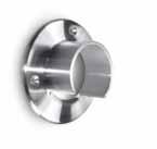
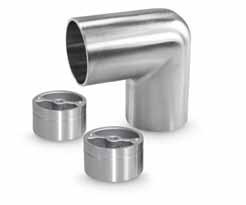
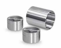
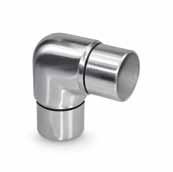
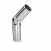
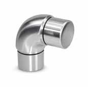
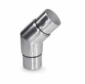
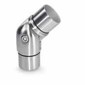
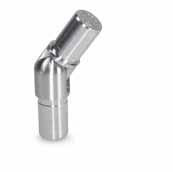
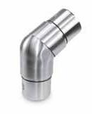
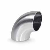
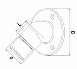
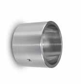
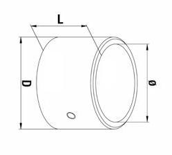
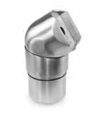
2500 48.3 30 27 1 Model 7070 End cap 304 Indoor cOdE ø 34.7070.420.S 42.4 1 34.7070.480.S 48.3 1 34.7070.600.S 60.3 1 Model 7070 End cap 316’s’ Outdoor cOdE ø 36.7070.420.S 42.4 1 36.7070.480.S 48.3 1 Model 7042-42.4mm rubber Set rubber Outdoor cOdE L U G 40.7042.010. r 5000 24 8-10 1 40.7042.012. r 5000 24 11.52-13.52 1 40.7042.015. r 5000 24 15-16.76 1 40.7042.019. r 5000 24 17.52-19 1 40.7042.020. r 5000 24 21.52 1 40.7142.010. r 2500 24 8-10 1 40.7142.012. r 2500 24 11.52-13.52 1 40.7142.015. r 2500 24 15-16.76 1 40.7142.019. r 2500 24 17.52-19 1 40.7142.019. r 2500 24 21.52 1 Model 7048-48.3mm rubber Set rubber Outdoor cOdE L U G 40.7048.012. r 5000 27 11.52-13.52 1 40.7048.015. r 5000 27 15-16.76 1 40.7048.019. r 5000 27 17.52-19 1 40.7048.020. r 5000 27 21.52 1 40.7148.012. r 2500 27 11.52-13.52 1 40.7148.015. r 2500 27 15-16.76 1 40.7148.019. r 2500 27 17.52-19 1 40.7148.020. r 2500 27 21.52 1 Model 7060-60.3mm rubber Set rubber Outdoor cOdE L U G 40.7060.015. r 5000 34 15-18 1 40.7060.019. r 5000 34 18.5-21.5 1 40.7060.025. r 5000 34 22-25 1 40.7160.015. r 2500 34 15-18 1 40.7160.019. r 2500 34 18.5-21.5 1 40.7160.025. r 2500 34 22-25 1 Model 7010 Elbow 304 Indoor cOdE L ø 34.7010.420.S 30 42.4 1 34.7010.480.S 35 48.3 1 34.7010.600.S 40 60.3 1 Model 7010 Elbow 316’s’ Outdoor cOdE L ø 36.7010.420.S 30 42.4 1 36.7010.480.S 35 48.3 1 Model 7020 Elbow 304 Indoor cOdE L ø 34.7020.420.S 30 42.4 1 34.7020.480.S 35 48.3 1 34.7020.600.S 40 60.3 1 Model 7020 Elbow 316’s’ Outdoor cOdE L ø 36.7020.420.S 30 42.4 1 36.7020.480.S 35 48.3 1 Model 7030 Adjustable elbow 304 Indoor cOdE L ø 34.7030.420.S 30 42.4 1 34.7030.480.S 35 48.3 1 Model 7030 Adjustable elbow 316’s’ Outdoor cOdE L ø 36.7030.420.S 30 42.4 1 36.7030.480.S 35 48.3 1 Model 7040 Adjustable elbow 304 Indoor cOdE L ø 34.7040.420.S 30 42.4 1 34.7040.480.S 35 48.3 1 Model 7040 Adjustable elbow 316’s’ Outdoor cOdE L ø 36.7040.420.S 30 42.4 1 36.7040.480.S 35 48.3 1 Model 7050 Joint connector 304 Indoor cOdE ø 34.7050.420.S 42.4 1 34.7050.480.S 48.3 1 34.7050.600.S 60.3 1 Model 7050 Joint connector 316’s’ Outdoor cOdE ø 36.7050.420.S 42.4 1 36.7050.480.S 48.3 1 Model 7060 Wall flange 304 Indoor cOdE d L ø 34.7060.420.S 90 30 42.4 1 34.7060.480.S 95 35 48.3 1 Model 7060 Wall flange 316’s’ Outdoor cOdE d L ø 36.7060.420.S 90 30 42.4 1 36.7060.480.S 95 35 48.3 1 www.fastechandrails.co.uk www.fastechandrails.co.uk
36.7100.600.S
48 49 HANDrAIL/FITTINGS HANDrAIL/FITTINGS MirrOr POLiSHEd Model 7000/7100 Handrail 304 Indoor cOdE L 34.7000.604.S 5000 1 34.7100.604.S 2500 1 Model 7020 Elbow 304 Indoor cOdE 34.7020.604.S 1 Model 7050 Joint connector 304 Indoor cOdE 34.7050.604.S 1 Model 7070 End cap 304 Indoor cOdE 34.7070.604.S 1 Model 7060 Wall flange 304 Indoor cOdE 34.7060.604.S 1 Model 7042-42.4mm rubber Set rubber Outdoor cOdE L U G 40.7042.010. r 5000 24 8-10 1 40.7042.012. r 5000 24 11.52-13.52 1 40.7042.015. r 5000 24 15-16.76 1 40.7042.019. r 5000 24 17.52-19 1 40.7042.020. r 5000 24 21.52 1 40.7142.010. r 2500 24 8-10 1 40.7142.012. r 2500 24 11.52-13.52 1 40.7142.015. r 2500 24 15-16.76 1 40.7142.019. r 2500 24 17.52-19 1 40.7142.019. r 2500 24 21.52 1 Model 7000 Handrail 304 Indoor cOdE L ø T U 34.7000.420.M 5000 42.4 24 24 1 34.7000.480.M 5000 48.3 30 27 1 Model 7000 Handrail 316 Outdoor cOdE L ø T U 36.7000.420.M 5000 42.4 24 24 1 36.7000.480.M 5000 48.3 30 27 1 Model 7042-42.4mm rubber Set rubber Outdoor cOdE L U G 40.7042.010. r 5000 24 8-10 1 40.7042.012. r 5000 24 11.52-13.52 1 40.7042.015. r 5000 24 15-16.76 1 40.7042.019. r 5000 24 17.52-19 1 40.7042.020. r 5000 24 21.52 1 40.7142.010. r 2500 24 8-10 1 40.7142.012. r 2500 24 11.52-13.52 1 40.7142.015. r 2500 24 15-16.76 1 40.7142.019. r 2500 24 17.52-19 1 40.7142.019. r 2500 24 21.52 1 Model 7048-48.3mm rubber Set rubber Outdoor cOdE L U G 40.7048.012. r 5000 27 11.52-13.52 1 40.7048.015. r 5000 27 15-16.76 1 40.7048.019. r 5000 27 17.52-19 1 40.7048.020. r 5000 27 21.52 1 40.7148.012. r 2500 27 11.52-13.52 1 40.7148.015. r 2500 27 15-16.76 1 40.7148.019. r 2500 27 17.52-19 1 40.7148.020. r 2500 27 21.52 1 Model 7070 End cap 304 Indoor cOdE ø 34.7070.420.M 42.4 1 34.7070.480.M 48.3 1 Model 7070 End cap 316’s’ Outdoor cOdE ø 36.7070.420.M 42.4 1 36.7070.480.M 48.3 1 www.fastechandrails.co.uk www.fastechandrails.co.uk
50 HANDrAIL/FITTINGS MirrOr POLiSHEd 0-60º Downwards 25-60º Upwards Model 7010 Elbow 304 Indoor cOdE L ø 34.7010.420.M 30 42.4 1 34.7010.480.M 35 48.3 1 Model 7010 Elbow 316’s’ Outdoor cOdE L ø 36.7010.420.M 30 42.4 1 36.7010.480.M 35 48.3 1 Model 7020 Elbow 304 Indoor cOdE L ø 34.7020.420.M 30 42.4 1 34.7020.480.M 35 48.3 1 Model 7020 Elbow 316’s’ Outdoor cOdE L ø 36.7020.420.M 30 42.4 1 36.7020.480.M 35 48.3 1 Model 7030 Adjustable elbow 304 Indoor cOdE L ø 34.7030.420.M 30 42.4 1 34.7030.480.M 35 48.3 1 Model 7030 Adjustable elbow 316’s’ Outdoor cOdE L ø 36.7030.420.M 30 42.4 1 36.7030.480.M 35 48.3 1 Model 7040 Adjustable elbow 304 Indoor cOdE L ø 34.7040.420.M 30 42.4 1 34.7040.480.M 35 48.3 1 Model 7040 Adjustable elbow 316’s’ Outdoor cOdE L ø 36.7040.420.M 30 42.4 1 36.7040.480.M 35 48.3 1 Model 7050 Joint connector 304 Indoor cOdE ø 34.7050.420.M 42.4 1 34.7050.480.M 48.3 1 Model 7050 Joint connector 316’s’ Outdoor cOdE ø 36.7050.420.M 42.4 1 36.7050.480.M 48.3 1 Model 7060 Wall flange 304 Indoor cOdE d L ø 34.7060.420.M 90 30 42.4 1 34.7060.480.M 95 35 48.3 1 Model 7060 Wall flange 316’s’ Outdoor cOdE d L ø 36.7060.420.M 90 30 42.4 1 36.7060.480.M 95 35 48.3 1 www.fastechandrails.co.uk
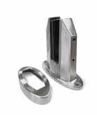
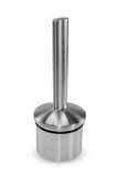
GLASS SPIGOTS

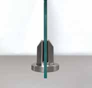
53
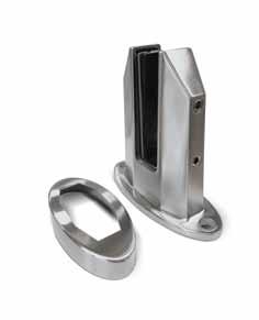
GLASS SPIGOTS
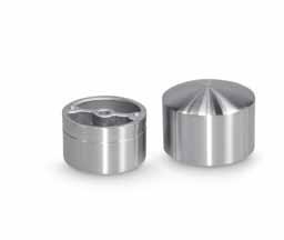
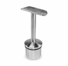
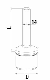
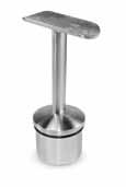
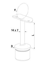
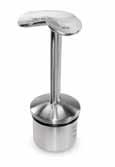
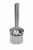
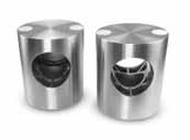
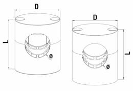
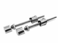
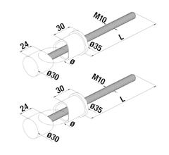
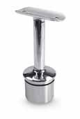
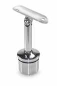
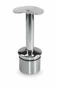
69 154 124 ø15 155 108 47 154 155 97 37 48 107 Model 5010 Top Mount 316’s’ Outdoor cOdE AdJUSTABLE G (MM) 36.5010.025.S YES 12-25.52 Model 5020 Side Mount 316’s’ Outdoor cOdE AdJUSTABLE G (MM) 36.5020.025.S YES 12-25.52 Model 5025 Side Mount Socket 316’s’ Outdoor cOdE 36.5025.000.T INFO FULLY ADJUSTABLE www.fastechandrails.co.uk

a ll s ha P es. a ll s izes Made to your r equire M ents at Co M petitive p ri C es

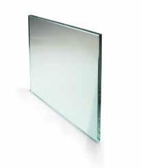
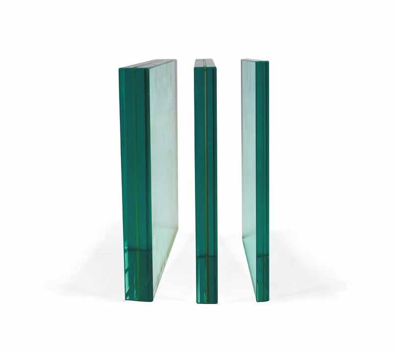
GLASS TOUGHENEd/LAMiNATEd
L H L H
GLASS
your o ne sTo P s ho P Toughened glass Glass Outdoor GLASS MM L H 12 12 TB c TB c 15 15 TB c TB c 19 19 TB c TB c 25 25 TB c TB c Laminated glass Glass Outdoor GLASS MM L H 12.76 6/6/2 TB c TB c 13.52 6/6/4 TB c TB c 16.76 8/8/2 TB c TB c 17.52 8/8/4 TB c TB c 20.76 10/10/2 TB c TB c 21.52 10/10/4 TB c TB c 25.52 12/12/4 TB c TB c 31.52 15/15/4 TB c TB c
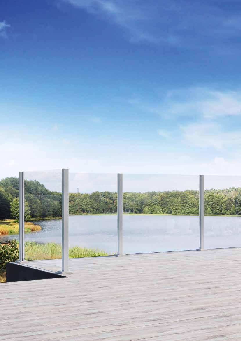
57 ALU-rAIL ALU-RAIL Model 8050 Seal Strips rubber Indoor cOdE G 40.8050.010. r 10-10.76 2 40.8050.011. r 11.52 2 40.8050.012. r 12-12.76 2 40.8050.013. r 13.52 2 Model 8010 End Post Aluminium Outdoor cOdE F NiSH 11.8010.110.A Silver Anodised 1 Model 8030 Corner Post Aluminium Outdoor cOdE F NiSH 11.8030.110.A Silver Anodised 1 Model 8020 Mid Post Aluminium Outdoor cOdE FiNiSH 11.8020.110.A Silver Anodised 1 End Post Middle Post Corner Post www.fastechandrails.co.uk
58 59 ALU-rAIL Installation Instructions ALU-rAIL Model 8050 Seal Strips rubber Indoor cOdE G 40.8050.010. r 10-10.76 2 40.8050.011. r 11.52 2 40.8050.012. r 12-12.76 2 40.8050.013. r 13.52 2 Model 8010 End Post Aluminium Outdoor cOdE FiN SH 11.8010.110.AG r AL 7016 1 Model 8030 Corner Post Aluminium Outdoor cOdE FiN SH 11.8030.110.AG r AL 7016 1 Model 8020 Mid Post Aluminium Outdoor cOdE F NiSH 11.8020.110.AG r AL 7016 1 www.fastechandrails.co.uk www.fastechandrails.co.uk
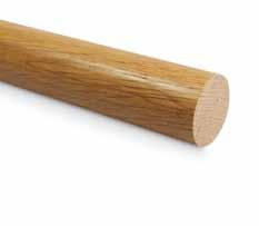


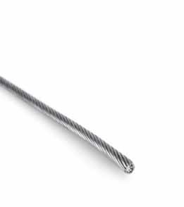
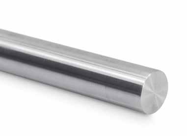
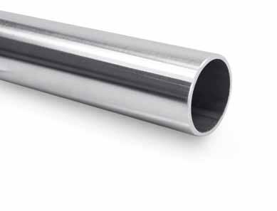
F i TT in G s T ubes and bar Timber- T ec a ccessories Wire-Tec 65-95 FITTI n GS 97-99 M I rr O r P OLIS h ED 101-113 G LASS cLAMPS 115 J ULIET B ALc O ny 117-119 G LASS cO nn E c TO r S & PA n EL hOLDE r S 121-122 W I r E F ITTI n GS 123 I n FO 125 T IMBE r h A n D r AIL 125-126 TIMBE r FITTI n GS 129 B A r 129 T UBE 131 TOOLS 131 G LUES A n D cLEA n E r S 132-133 B OLTS A n D S cr EWS Fast-Fit® Aligns and Secures 316's' ' Superior ' c orrosion r esistance with 2205
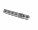
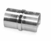
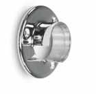
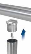
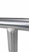
Fast-Fit®
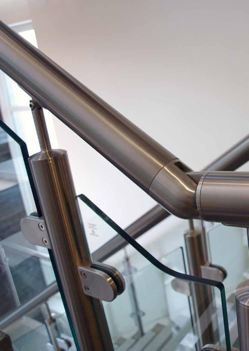
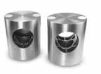
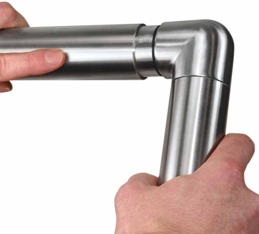
CENTrALISES AND ALIGNS
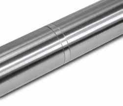
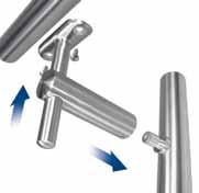
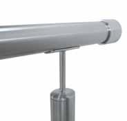
Once inserted the unique rubber sleeve compresses equally around the circumference compensating for any movement between the fittings and tube. This equal compression centralises the fitting with the tube ensuring a consistent alignment between the two parts.
SECUrES AND STABILISES
To help enable a secure and seamless fit for your joints Fast-Fit will securely hold the fitting in place whilst the glue is curing preventing gaps from forming through movement and vibration. By tightly securing the fitting to the tube it allows the installer to move onto the next joint without the need for extra remedial works to hold the fitting and tube together whilst the glue cures.
SAVING TIME AND MONEY
The simple solution that the Fast-Fit system offers is based on the key principles of saving time and money for the installer. To help with this cost reduction the Fast-Fit range will be charged at no extra cost allowing installers all the benefits of the Fast-Fit system at the same competitive price.

QUICKEr INSTALLATION TIMES
Having the benefit of aligning and securing each joint Fast-Fit allows installation times to be reduced by upto 20%. The Fast-Fit unique innovation means installers do not need to take extra remedial work to secure the joints or wait until the glue cures before proceeding but can quickly progress from one joint to the next.
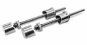
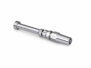
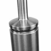
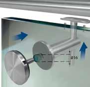
The Fastec ‘Fast-Fit’ system has been developed to help installers by aligning and securing the fitting into the tube until the glue cures. With just a simple push and twist the Fast-Fit rubber sleeve slides into the tube firmly holding and aligning the fitting. This allows installers to move onto the next joint safe in the knowledge that the fitting will be held correctly in position without vibrating loose or misaligning.
AVAILABLE FOr ALL GLUED INSErTS
The Fast-Fit system is available on all glued inserts for 48.3mm and 42.4mm diameter connectors, this means that the whole range has been incorporated giving the installer the benefit of the Fast-Fit system on all glued inserts.
63
Patent Application No. 1215466.2 *We reserve the right to supply non Fast-Fit fittings if necessary to fulfil orders. The Perfect Fit 62


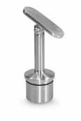
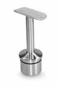

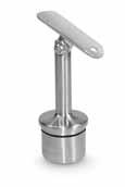
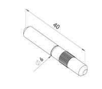
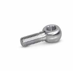
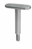
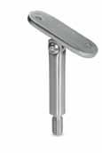
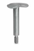
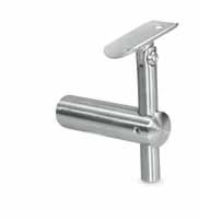
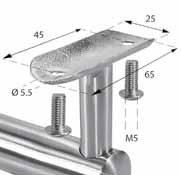
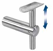
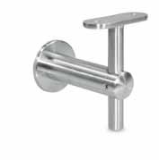
65 FITTINGS Model 0100 Stem 304 Indoor cOdE d L BOLT 34.0100.422.S 42.4 x 2.0 80 FF-12 34.0100.426.S 42.4 x 2.6 80 FF-12 34.0100.482.S 48.3 x 2.0 80 FF-12 34.0100.486.S 48.3 x 2.6 80 FF-12 Model 0100 Stem 316’s’ Outdoor cOdE d L BOLT 36.0100.422.S 42.4 x 2.0 80 FF-13 36.0100.426.S 42.4 x 2.6 80 FF-13 36.0100.482.S 48.3 x 2.0 80 FF-13 36.0100.486.S 48.3 x 2.6 80 FF-13 Model 0105 Adj Stem 304 Indoor cOdE d L BOLT 34.0105.422.S 42.4 x 2.0 80 FF-12 34.0105.426.S 42.4 x 2.6 80 FF-12 34.0105.482.S 48.3 x 2.0 80 FF-12 34.0105.486.S 48.3 x 2.6 80 FF-12 Model 0105 Adj Stem 316’s’ Outdoor cOdE d L BOLT 36.0105.422.S 42.4 x 2.0 80 FF-13 36.0105.426.S 42.4 x 2.6 80 FF-13 36.0105.482.S 48.3 x 2.0 80 FF-13 36.0105.486.S 48.3 x 2.6 80 FF-13 Model 0110 Stem 304 Indoor cOdE d L ø BOLT 34.0110.422.S 42.4 x 2.0 80 42.4 FF-10 34.0110.426.S 42.4 x 2.6 80 42.4 FF-10 34.0110.482.S 48.3 x 2.0 80 48.3 FF-10 34.0110.486.S 48.3 x 2.6 80 48.3 FF-10 Model 0111 Stem 304 Indoor cOdE d L ø BOLT 34.0111.422.S 42.4 x 2.0 80 48.3 FF-10 34.0111.426.S 42.4 x 2.6 80 48.3 FF-10 34.0111.486.S 48.3 x 2.6 80 42.4 FF-10 Model 0110 Stem 316’s’ Outdoor cOdE d L ø BOLT 36.0110.422.S 42.4 x 2.0 80 42.4 FF-11 36.0110.426.S 42.4 x 2.6 80 42.4 FF-11 36.0110.482.S 48.3 x 2.0 80 48.3 FF-11 36.0110.486.S 48.3 x 2.6 80 48.3 FF-11 Model 0111 Stem 316’s’ Outdoor cOdE d L ø BOLT 36.0111.422.S 42.4 x 2.0 80 48.3 FF-11 36.0111.426.S 42.4 x 2.6 80 48.3 FF-11 36.0111.486.S 48.3 x 2.6 80 42.4 FF-11 Model 0115 Adj Stem 304 Indoor cOdE d L ø BOLT 34.0115.422.S 42.4 x 2.0 80 42.4 FF-10 34.0115.426.S 42.4 x 2.6 80 42.4 FF-10 34.0115.482.S 48.3 x 2.0 80 48.3 FF-10 34.0115.486.S 48.3 x 2.6 80 48.3 FF-10 Model 0116 Adj Stem 304 Indoor cOdE d L ø BOLT 34.0116.426.S 42.4 x 2.6 80 48.3 FF-10 34.0116.486.S 48.3 x 2.6 80 42.4 FF-10 Model 0115 Adj Stem 316’s’ Outdoor cOdE d L ø BOLT 36.0115.422.S 42.4 x 2.0 80 42.4 FF-11 36.0115.426.S 42.4 x 2.6 80 42.4 FF-11
48.3 x 2.0 80 48.3 FF-11 36.0115.486.S 48.3 x 2.6 80 48.3 FF-11 Model 0116 Adj Stem 316’s’ Outdoor cOdE d L ø BOLT 36.0116.426.S 42.4 x 2.6 80 48.3 FF-11 36.0116.486.S 48.3 x 2.6 80 42.4 FF-11 FrEE FIXINGS FrEE FIXINGS FrEE FIXINGS FrEE FIXINGS STEM CONNECTOrS www.fastechandrails.co.uk
36.0115.482.S
STEM CONNECTOrS
66 67 ACCESSOrIES INFO
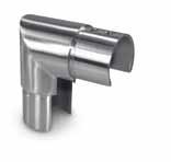
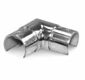
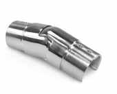
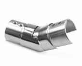
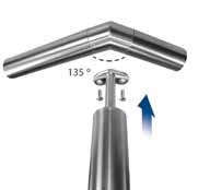
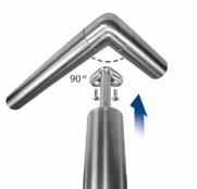
Model 0120 135º Stem 304 Indoor cOdE d L ø BOLT 34.0120.422.S 42.4 x 2.0 80 42.4 FF-10 34.0120.426.S 42.4 x 2.6 80 42.4 FF-10 34.0120.482.S 48.3 x 2.0 80 48.3 FF-10 34.0120.486.S 48.3 x 2.6 80 48.3 FF-10 Model 0121 135º Stem 304 Indoor cOdE d L ø BOLT 34.0121.422.S 42.4 x 2.0 80 48.3 FF-10 34.0121.426.S 42.4 x 2.6 80 48.3 FF-10 34.0121.486.S 48.3 x 2.6 80 42.4 FF-10 Model 0120 135º Stem 316’s’ Outdoor cOdE d L ø BOLT 36.0120.422.S 42.4 x 2.0 80 42.4 FF-11 36.0120.426.S 42.4 x 2.6 80 42.4 FF-11 36.0120.482.S 48.3 x 2.0 80 48.3 FF-11 36.0120.486.S 48.3 x 2.6 80 48.3 FF-11 Model 0121 135º Stem 316’s’ Outdoor cOdE d L ø BOLT 36.0121.422.S 42.4 x 2.0 80 48.3 FF-11 36.0121.426.S 42.4 x 2.6 80 48.3 FF-11 36.0121.486.S 48.3 x 2.6 80 42.4 FF-11 Model 0130 90º Stem 304 Indoor cOdE d L ø BOLT 34.0130.422.S 42.4 x 2.0 80 42.4 FF-10 34.0130.426.S 42.4 x 2.6 80 42.4 FF-10 34.0130.482.S 48.3 x 2.0 80 48.3 FF-10 34.0130.486.S 48.3 x 2.6 80 48.3 FF-10 Model 0131 90º Stem 304 Indoor cOdE d L ø BOLT 34.0131.422.S 42.4 x 2.0 80 48.3 FF-10 34.0131.426.S 42.4 x 2.6 80 48.3 FF-10 34.0131.486.S 48.3 x 2.6 80 42.4 FF-10 Model 0130 90º Stem 316’s’ Outdoor cOdE d L ø BOLT 36.0130.422.S 42.4 x 2.0 80 42.4 FF-11 36.0130.426.S 42.4 x 2.6 80 42.4 FF-11 36.0130.482.S 48.3 x 2.0 80 48.3 FF-11 36.0130.486.S 48.3 x 2.6 80 48.3 FF-11 Model 0131 90º Stem 316’s’ Outdoor cOdE d L ø BOLT 36.0131.422.S 42.4 x 2.0 80 48.3 FF-11 36.0131.426.S 42.4 x 2.6 80 48.3 FF-11 36.0131.486.S 48.3 x 2.6 80 42.4 FF-11 FrEE FIXINGS FrEE FIXINGS PAGE 131 Glue 50 ml 10.9010.000.A STEM CONNECTOrS Model 0135 Stem/Adj Corner 304 Indoor cOdE d L 34.0135.422.S 42.4 x 2.0 30 34.0135.426.S 42.4 x 2.6 30 34.0135.482.S 48.3 x 2.0 30 34.0135.486.S 48.3 x 2.6 30 Model 0135 Stem/Adj Corner 316’s’ Outdoor cOdE d L 36.0135.422.S 42.4 x 2.0 30 36.0135.426.S 42.4 x 2.6 30 36.0135.482.S 48.3 x 2.0 30 36.0135.486.S 48.3 x 2.6 30 Model 0140 Weldable Stem 304 Indoor cOdE d L 34.0140.422.S 42.4 x 2.0 80 34.0140.426.S 42.4 x 2.6 80 34.0140.482.S 48.3 x 2.0 80 34.0140.486.S 48.3 x 2.6 80 Model 0140 Weldable Stem 316’s’ Outdoor cOdE d L 36.0140.422.S 42.4 x 2.0 80 36.0140.426.S 42.4 x 2.6 80 36.0140.482.S 48.3 x 2.0 80 36.0140.486.S 48.3 x 2.6 80 P PROTECTED DESIGN www.fastechandrails.co.uk www.fastechandrails.co.uk

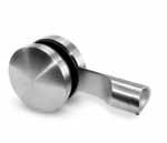
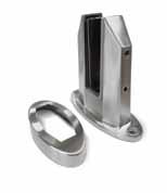
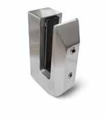
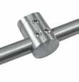
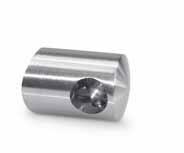
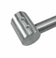
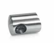
BLADE
Stem Connector
68 69 BLADE STEM CONNECTOrS BLADE STEM CONNECTOrS
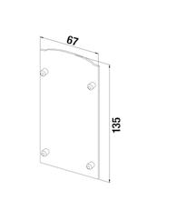
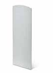
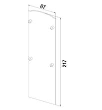
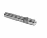
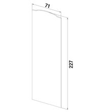
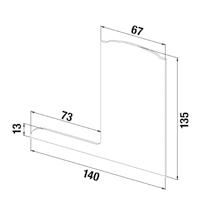
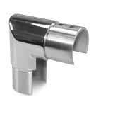
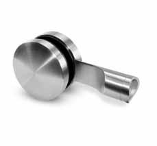
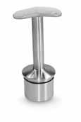
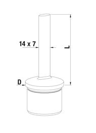
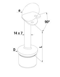
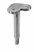
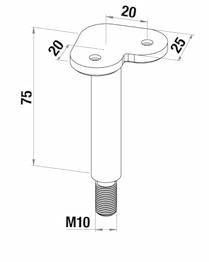
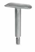
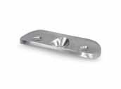
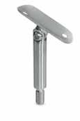
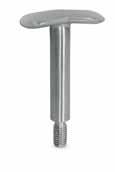
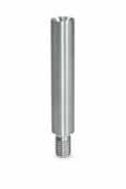
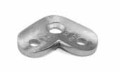
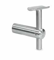
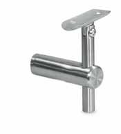
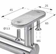
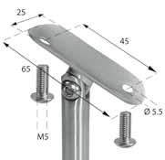
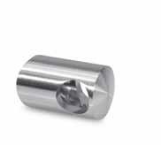
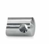
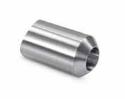
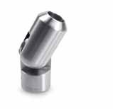
Model 0150 Blade Stem 304 Indoor cOdE d L ø BOLT 34.0150.422.S 42.4 x 2.0 80 42.4 FF-10 34.0150.426.S 42.4 x 2.6 80 42.4 FF-10 34.0150.482.S 48.3 x 2.0 80 48.3 FF-10 34.0150.486.S 48.3 x 2.6 80 48.3 FF-10 Model 0150 Blade Stem 316’s’ Outdoor cOdE d L ø BOLT 36.0150.422.S 42.4 x 2.0 80 42.4 FF-11 36.0150.426.S 42.4 x 2.6 80 42.4 FF-11 36.0150.482.S 48.3 x 2.0 80 48.3 FF-11 36.0150.486.S 48.3 x 2.6 80 48.3 FF-11 Model 0157 Weldable Blade Stem 304 Indoor cOdE d L ø 34.0157.422.S 42.4 x 2.0 80 42.4 34.0157.426.S 42.4 x 2.6 80 42.4 34.0157.482.S 48.3 x 2.0 80 48.3 34.0157.486.S 48.3 x 2.6 80 48.3 Model 0157 Weldable Blade Stem 316’s’ Outdoor cOdE d L ø 36.0157.422.S 42.4 x 2.0 80 42.4 36.0157.426.S 42.4 x 2.6 80 42.4 36.0157.482.S 48.3 x 2.0 80 48.3 36.0157.486.S 48.3 x 2.6 80 48.3 Model 0155 90º Blade Stem 304 Indoor cOdE d L ø BOLT 34.0155.422.S 42.4 x 2.0 80 42.4 FF-10 34.0155.426.S 42.4 x 2.6 80 42.4 FF-10 34.0155.482.S 48.3 x 2.0 80 48.3 FF-10 34.0155.486.S 48.3 x 2.6 80 48.3 FF-10 Model 0155 90º Blade Stem 316’s’ Outdoor cOdE d L ø BOLT
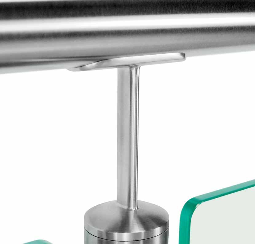
42.4 x 2.0 80 42.4 FF-11 36.0155.426.S 42.4 x 2.6 80 42.4 FF-11 36.0155.482.S 48.3 x 2.0 80 48.3 FF-11 36.0155.486.S 48.3 x 2.6 80 48.3 FF-11 FrEE FIXINGS FrEE FIXINGS technical innovationmastery creativity Slimmer profile and simple lines at any angle Patent Application No. 1215466.2 Design Protection No. 006563581 Fast-Fit Aligns and Secures P PROTECTED DESIGN P PROTECTED DESIGN www.fastechandrails.co.uk www.fastechandrails.co.uk
36.0155.422.S

70 71
Model 0200 Stem 304 Indoor cOdE BOLT 34.0200.000.S FF-12 Model 0200 Stem 316’s’ Outdoor cOdE BOLT 36.0200.000.S FF-13 Model 0220 90º Stem 304 Indoor cOdE BOLT 34.0220.000.S FF-12 Model 0220 90º Stem 316’s’ Outdoor cOdE BOLT 36.0220.000.S FF-13 Model 0205 Adj Stem 304 Indoor cOdE BOLT 34.0205.000.S FF-12 Model 0205 Adj Stem 316’s’ Outdoor cOdE BOLT 36.0205.000.S FF-13 FrEE FIXINGS FrEE FIXINGS FrEE FIXINGS Model 0200 Stem 304 Indoor cOdE ø BOLT 34.0200.420.S 42.4 FF-10 34.0200.480.S 48.3 FF-10 Model 0200 Stem 316’s’ Outdoor cOdE ø BOLT 36.0200.420.S 42.4 FF-11 36.0200.480.S 48.3 FF-11 Model 0205 Adj Stem 304 Indoor cOdE ø BOLT 34.0205.420.S 42.4 FF-10 34.0205.480.S 48.3 FF-10 Model 0205 Adj Stem 316’s’ Outdoor cOdE ø BOLT 36.0205.420.S 42.4 FF-11 36.0205.480.S 48.3 FF-11 FrEE FIXINGS FrEE FIXINGS Model 0210 Adj Stem 304 Indoor cOdE ø BOLT 34.0210.420.S 42.4 FF-10 34.0210.480.S 48.3 FF-10 Model 0210 Adj Stem 316’s’ Outdoor cOdE ø BOLT 36.0210.420.S 42.4 FF-11 36.0210.480.S 48.3 FF-11 FrEE FIXINGS HANDrAIL SADDLE/STEMS Model 0300 Saddle 304 Indoor cOdE BOLT 34.0300.000.S FF-12 Model 0300 Saddle 316’s’ Outdoor cOdE BOLT 36.0300.000.S FF-13 FrEE FIXINGS Model 0220 90º Stem 304 Indoor cOdE ø BOLT 34.0220.420.S 42.4 FF-10 34.0220.480.S 48.3 FF-10 Model 0220 90º Stem 316’s’ Outdoor cOdE ø BOLT 36.0220.420.S 42.4 FF-11 36.0220.480.S 48.3 FF-11 FrEE FIXINGS Model 0310 Stem 304 Indoor cOdE BOLT 34.0310.000.S FF-48 Model 0310 Stem 316 Outdoor cOdE BOLT 36.0310.000.S FF-49 Model 0315 Adj Stem 304 Indoor cOdE BOLT 34.0315.000.S FF-48 Model 0315 Adj Stem 316’s’ Outdoor cOdE BOLT 36.0315.000.S FF-49 FrEE FIXINGS FrEE FIXINGS Model 0300 Saddle 304 Indoor cOdE ø BOLT 34.0300.420.S 42.4 FF-10 34.0300.480.S 48.3 FF-10 Model 0300 Saddle 316’s’ Outdoor cOdE ø BOLT 36.0300.420.S 42.4 FF-11 36.0300.480.S 48.3 FF-11 FrEE FIXINGS Model 0303 90º Saddle 304 Indoor cOdE ø BOLT 34.0303.420.S 42.4 FF-10 34.0303.480.S 48.3 FF-10 Model 0303 90º Saddle 316’s’ Outdoor cOdE ø BOLT 36.0303.420.S 42.4 FF-11 36.0303.480.S 48.3 FF-11 FrEE FIXINGS www.fastechandrails.co.uk www.fastechandrails.co.uk
STEM AND SADDLES


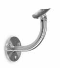
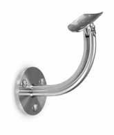
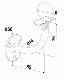
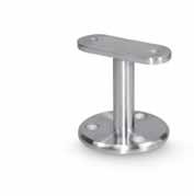
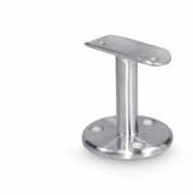
72 73 HANDrAIL BrACKETS POST Fix Model 0400 Handrail Bracket 304 Indoor cOdE BOLT 34.0400.000.S FF-12/FF-21 Model 0400 Handrail Bracket 316’s’ Outdoor cOdE BOLT 36.0400.000.S FF-13/FF-22 FrEE FIXINGS Model 0405 Adj Handrail Bracket 304 Indoor cOdE ø BOLT 34.0405.420.S 42.4 FF-10/FF-21 34.0405.480.S 48.3 FF-10/FF-21 Model 0405 Adj Handrail Bracket 316’s’ Outdoor cOdE ø BOLT 36.0405.420.S 42.4 FF-11/FF-22 36.0405.480.S 48.3 FF-11/FF-22 FrEE FIXINGS INFO INFO ‘Part M’ requirement HANDrAIL BrACKETS POST Fix Model 0425/0426 Handrail Bracket 304 Indoor cOdE d ø BOLT 34.0425.420.S 42.4 42.4 FF-10/FF-21 34.0425.480.S 48.3 48.3 FF-10/FF-21 Model 0425/0426 Handrail Bracket 316’s’ Outdoor cOdE d ø BOLT 36.0425.420.S 42.4 42.4 FF-11/FF-22 36.0425.480.S 48.3 48.3 FF-11/FF-22 FrEE FIXINGS INFO INFO ‘Part M’ requirement Model 0420/0421 Handrail Bracket 304 Indoor cOdE d ø BOLT 34.0420.420.S 42.4 42.4 FF-10/FF-21 34.0420.480.S 48.3 48.3 FF-10/FF-21 Model 0420/0421 Handrail Bracket 316’s’ Outdoor cOdE d ø BOLT 36.0420.420.S 42.4 42.4 FF-11/FF-22 36.0420.480.S 48.3 48.3 FF-11/FF-22 FrEE FIXINGS Model 0400 Handrail Bracket 304 Indoor cOdE ø BOLT 34.0400.420.S 42.4 FF-10/FF-21 34.0400.480.S 48.3 FF-10/FF-21 Model 0400 Handrail Bracket 316’s’ Outdoor cOdE ø BOLT 36.0400.420.S 42.4 FF-11/FF-22 36.0400.480.S 48.3 FF-11/FF-22 FrEE FIXINGS Model 0415 Adj Handrail Bracket 304 Indoor cOdE ø BOLT 34.0415.420.S 42.4 FF-12/FF-21 34.0415.480.S 48.3 FF-12/FF-21 Model 0415 Adj Handrail Bracket 316’s’ Outdoor cOdE ø BOLT 36.0415.420.S 42.4 FF-13/FF-22 36.0415.480.S 48.3 FF-13/FF-22 FrEE FIXINGS www.fastechandrails.co.uk www.fastechandrails.co.uk
74 75 HANDrAIL BrACKETS WALL Fix INFO INFO ‘Part M’ requirement Model 0430 Handrail Bracket 304 Indoor cOdE BOLT 34.0430.000.S FF-12 Model 0430 Handrail Bracket 316’s’ Outdoor cOdE BOLT 36.0430.000.S FF-13 Model 0435 Adj Handrail Bracket 304 Indoor cOdE BOLT 34.0435.000.S FF-12 Model 0435 Adj Handrail Bracket 316’s’ Outdoor cOdE BOLT 36.0435.000.S FF-13 Model 0430 Handrail Bracket 304 Indoor cOdE ø BOLT 34.0430.420.S 42.4 FF-10 34.0430.480.S 48.3 FF-10 Model 0430 Handrail Bracket 316’s’ Outdoor cOdE ø BOLT 36.0430.420.S 42.4 FF-11 36.0430.480.S 48.3 FF-11 Model 0435 Adj Handrail Bracket 304 Indoor cOdE ø BOLT 34.0435.420.S 42.4 FF-10 34.0435.480.S 48.3 FF-10 Model 0435 Adj Handrail Bracket 316’s’ Outdoor cOdE ø BOLT 36.0435.420.S 42.4 FF-11 36.0435.480.S 48.3 FF-11 FrEE FIXINGS FrEE FIXINGS FrEE FIXINGS FrEE FIXINGS HANDrAIL BrACKETS GLASS Fix INFO INFO ‘Part M’ requirement Model 0440 Handrail Bracket 304 Indoor cOdE BOLT 34.0440.000.S FF-12 Model 0440 Handrail Bracket 316’s’ Outdoor cOdE BOLT 36.0440.000.S FF-13 Model 0445 Adj Handrail Bracket 304 Indoor cOdE BOLT 34.0445.000.S FF-12 Model 0445 Adj Handrail Bracket 316’s’ Outdoor cOdE BOLT 36.0445.000.S FF-13 Model 0440 Handrail Bracket 304 Indoor cOdE ø BOLT 34.0440.420.S 42.4 FF-10 34.0440.480.S 48.3 FF-10 Model 0440 Handrail Bracket 316’s’ Outdoor cOdE ø BOLT 36.0440.420.S 42.4 FF-11 36.0440.480.S 48.3 FF-11 Model 0445 Adj Handrail Bracket 304 Indoor cOdE ø BOLT 34.0445.420.S 42.4 FF-10 34.0445.480.S 48.3 FF-10 Model 0445 Adj Handrail Bracket 316’s’ Outdoor cOdE ø BOLT 36.0445.420.S 42.4 FF-11 36.0445.480.S 48.3 FF-11 FrEE FIXINGS FrEE FIXINGS FrEE FIXINGS FrEE FIXINGS www.fastechandrails.co.uk www.fastechandrails.co.uk
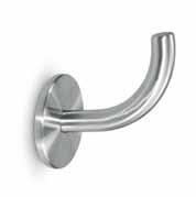
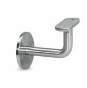
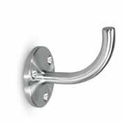
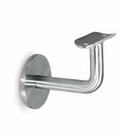
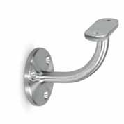
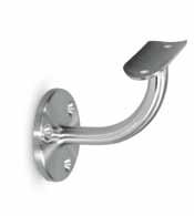
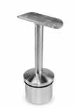
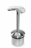
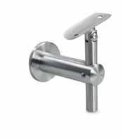
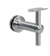
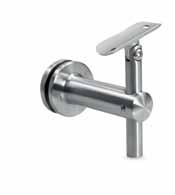
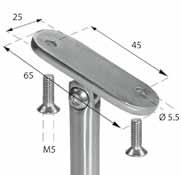
76 77 HANDrAIL BrACKETS WALL Fix Model 0510 Handrail Bracket 304 Indoor cOdE 34.0510.000.S Model 0510 Handrail Bracket 316’s’ Outdoor cOdE 36.0510.000.S Model 0520 Handrail Bracket 304 Indoor cOdE 34.0520.000.S Model 0520 Handrail Bracket 316’s’ Outdoor cOdE 36.0520.000.S Model 0511 Handrail Bracket 304 Indoor cOdE BOLT 34.0511.000.S FF-12 Model 0511 Handrail Bracket 316’s’ Outdoor cOdE BOLT 36.0511.000.S FF-13 Model 0521 Handrail Bracket 304 Indoor cOdE BOLT 34.0521.000.S FF-12 Model 0521 Handrail Bracket 316’s’ Outdoor cOdE BOLT 36.0521.000.S FF-13 FrEE FIXINGS FrEE FIXINGS Model 0511 Handrail Bracket 304 Indoor cOdE ø BOLT 34.0511.420.S 42.4 FF-10 34.0511.480.S 48.3 FF-10 Model 0511 Handrail Bracket 316’s’ Outdoor cOdE ø BOLT 36.0511.420.S 42.4 FF-11 36.0511.480.S 48.3 FF-11 Model 0521 Handrail Bracket 304 Indoor cOdE ø BOLT 34.0521.420.S 42.4 FF-10 34.0521.480.S 48.3 FF-10 Model 0521 Handrail Bracket 316’s’ Outdoor cOdE ø BOLT 36.0521.420.S 42.4 FF-11 36.0521.480.S 48.3 FF-11 FrEE FIXINGS FrEE FIXINGS HANDrAIL SUPPOrTS Model 0530 Handrail Support 304 Indoor cOdE BOLT 34.0530.000.S FF-12 Model 0530 Handrail Support 316’s’ Outdoor cOdE BOLT 36.0530.000.S FF-13 FrEE FIXINGS Model 0530 Handrail Support 304 Indoor cOdE ø BOLT 34.0530.420.S 42.4 FF-10 34.0530.480.S 48.3 FF-10 Model 0530 Handrail Support 316’s’ Outdoor cOdE ø BOLT 36.0530.420.S 42.4 FF-11 36.0530.480.S 48.3 FF-11 Model 0540 rosette 304 Indoor cOdE 34.0540.070.S Model 0542 Cover 304 Indoor cOdE ø 34.0542.012.S 12 Model 0541 90º Stem 304 Indoor cOdE BOLT 34.0541.000.S FF-48 FrEE FIXINGS FrEE FIXINGS Model 0525 Handrail Bracket 304 Indoor cOdE ø BOLT 34.0525.420.S 42.4 FF-10 34.0525.480.S 48.3 FF-10 Model 0521 Handrail Bracket 316’s’ Outdoor cOdE ø BOLT 36.0525.420.S 42.4 FF-11 36.0525480.S 48.3 FF-11 FrEE FIXINGS www.fastechandrails.co.uk www.fastechandrails.co.uk

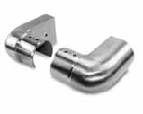
78 79 ELBOWS INFO ACCESSOrIES PAGE 131 Glue 50 ml 10.9010.000.A Model 0600 90º Elbow 304 Indoor cOdE L ø 34.0600.422.S 30 42.4 x 2.0 34.0600.426.S 30 42.4 x 2.6 34.0600.482.S 35 48.3 x 2.0 34.0600.486.S 35 48.3 x 2.6 Model 0600 90º Elbow 316’s’ Outdoor cOdE L ø 36.0600.422.S 30 42.4 x 2.0 36.0600.426.S 30 42.4 x 2.6 36.0600.482.S 35 48.3 x 2.0 36.0600.486.S 35 48.3 x 2.6 Model 0620 90º Elbow 304 Indoor cOdE L ø
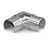
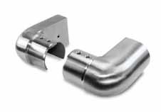
30 42.4 x 2.0 34.0620.426.S 30 42.4 x 2.6 34.0620.482.S 35 48.3 x 2.0 34.0620.486.S 35 48.3 x 2.6 Model 0620 90º Elbow 316’s’ Outdoor cOdE L ø 36.0620.422.S 30 42.4 x 2.0 36.0620.426.S 30 42.4 x 2.6 36.0620.482.S 35 48.3 x 2.0 36.0620.486.S 35 48.3 x 2.6 Model 0610 90º Elbow 304 Indoor cOdE L ø 34.0610.422.S 30 42.4 x 2.0 34.0610.426.S 30 42.4 x 2.6 34.0610.482.S 35 48.3 x 2.0 34.0610.486.S 35 48.3 x 2.6 Model 0610 90º Elbow 316’s’ Outdoor cOdE L ø 36.0610.422.S 30 42.4 x 2.0 36.0610.426.S 30 42.4 x 2.6 36.0610.482.S 35 48.3 x 2.0 36.0610.486.S 35 48.3 x 2.6 Model 0630 135º Elbow 304 Indoor cOdE L ø 34.0630.422.S 30 42.4 x 2.0 34.0630.426.S 30 42.4 x 2.6 34.0630.482.S 35 48.3 x 2.0 34.0630.486.S 35 48.3 x 2.6 Model 0630 135º Elbow 316’s’ Outdoor cOdE L ø 36.0630.422.S 30 42.4 x 2.0 36.0630.426.S 30 42.4 x 2.6 36.0630.482.S 35 48.3 x 2.0 36.0630.486.S 35 48.3 x 2.6 ELBOWS Model 0640 Adj Elbow 304 Indoor cOdE L ø 34.0640.012.S 35 12 Model 0640 Adj Elbow 316’s’ Outdoor cOdE L ø 36.0640.012.S 35 12 Model 0640 Adj Elbow 304 Indoor cOdE L ø 34.0640.422.S 27 42.4 x 2.0 34.0640.426.S 27 42.4 x 2.6 34.0640.482.S 30 48.3 x 2.0 34.0640.486.S 30 48.3 x 2.6 Model 0640 Adj Elbow 316’s’ Outdoor cOdE L ø 36.0640.422.S 27 42.4 x 2.0 36.0640.426.S 27 42.4 x 2.6 36.0640.482.S 30 48.3 x 2.0 36.0640.486.S 30 48.3 x 2.6 Model 0645 Adj Elbow 304 Indoor cOdE L ø 34.0645.422.S 30 42.4 x 2.0 34.0645.426.S 30 42.4 x 2.6 34.0645.482.S 35 48.3 x 2.0 34.0645.486.S 35 48.3 x 2.6 Model 0645 Adj Elbow 316’s’ Outdoor cOdE L ø 36.0645.422.S 30 42.4 x 2.0 36.0645.426.S 30 42.4 x 2.6 36.0645.482.S 35 48.3 x 2.0 36.0645.486.S 35 48.3 x 2.6 Model 0640 Adj Elbow 304 Indoor cOdE ø 34.0640.016.S 16 x 1.0 Model 0640 Adj Elbow 316’s’ Outdoor cOdE L ø 36.0640.016.S 35 16 x 1.0 304 Model 0650 304 Indoor cOdE L ø 34.0650.420.S 65 42.4 34.0650.480.S 75 48.3 316’s’ Model 0650 316’s’ Outdoor cOdE L ø 36.0650.420.S 65 42.4 36.0650.480.S 75 48.3 P PROTECTED DESIGN www.fastechandrails.co.uk www.fastechandrails.co.uk
34.0620.422.S
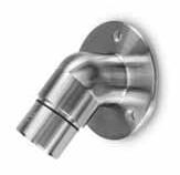
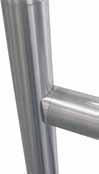
seamless adjustment is now here
Fastec’s new adjustable fittings allow seamless change in directions without compromising the shape and feel of the handrail
80 81
INFO Model 0660 304 Indoor cOdE L ø 34.0660.422.S 80 42.4 x 2.0 34.0660.426.S 80 42.4 x 2.6 34.0660.482.S 85 48.3 x 2.0 34.0660.486.S 85 48.3 x 2.6 Model 0660 316’s’ Outdoor cOdE L ø 36.0660.422.S 80 42.4 x 2.0 36.0660.426.S 80 42.4 x 2.6 36.0660.482.S 85 48.3 x 2.0 36.0660.486.S 85 48.3 x 2.6 Model 0710 304 Indoor cOdE L ø 34.0710.422.S 60 42.4 x 2.0 34.0710.426.S 60 42.4 x 2.6 34.0710.482.S 70 48.3 x 2.0 34.0710.486.S 70 48.3 x 2.6 Model 0710 316’s’ Outdoor cOdE L ø 36.0710.422.S 60 42.4 x 2.0 36.0710.426.S 60 42.4 x 2.6 36.0710.482.S 70 48.3 x 2.0 36.0710.486.S 70 48.3 x 2.6 Model 0700 304 Indoor cOdE L ø 34.0700.422.S 30 42.4 x 2.0 34.0700.426.S 30 42.4 x 2.6 34.0700.482.S 35 48.3 x 2.0 34.0700.486.S 35 48.3 x 2.6 Model 0700 316’s’ Outdoor cOdE L ø 36.0700.422.S 30 42.4 x 2.0 36.0700.426.S 30 42.4 x 2.6 36.0700.482.S 35 48.3 x 2.0 36.0700.486.S 35 48.3 x 2.6 Model 0720 304 Indoor cOdE ø 34.0720.422.S 42.4 x 2.0 34.0720.426.S 42.4 x 2.6 34.0720.482.S 48.3 x 2.0 34.0720.486.S 48.3 x 2.6 Model 0720 316’s’ Outdoor cOdE ø 36.0720.422.S 42.4 x 2.0 36.0720.426.S 42.4 x 2.6 36.0720.482.S 48.3 x 2.0 36.0720.486.S 48.3 x 2.6
CONNECTOrS
www.fastechandrails.co.uk www.fastechandrails.co.uk
Slimmer profile and simple lines at any angle

CONNECTOrS
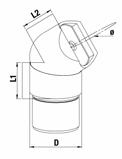
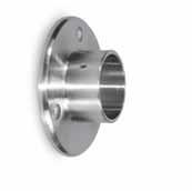
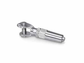
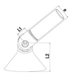
82 83 CONNECTOrS INFO Model 0731/0732 Adaptor 304 Indoor cOdE d ø BOLT 34.0731.422.S 42.4 x 2.0 42.4 FF-45 34.0731.426.S 42.4 x 2.6 42.4 FF-45 34.0731.482.S 48.3 x 2.0 48.3 FF-45 34.0731.482.S 48.3 x 2.6 48.3 FF-45 34.0732.422.S 42.4 x 2.0 48.3 FF-45 34.0732.426.S 42.4 x 2.6 48.3 FF-45 Model 0731/0732 Adaptor 316’s’ Outdoor cOdE d ø BOLT 36.0731.422.S 42.4 x 2.0 42.4 FF-46 36.0731.426.S 42.4 x 2.6 42.4 FF-46 36.0731.482.S 48.3 x 2.0 48.3 FF-46 36.0731.482.S 48.3 x 2.0 48.3 FF-46 36.0732.482.S 42.4 x 2.0 48.3 FF-46 36.0732.486.S 42.4 x 2.6 48.3 FF-46 Model 0730 Adaptor 304 Indoor cOdE d BOLT 34.0730.422.S 42.4 x 2.0 FF-45 34.0730.426.S 42.4 x 2.6 FF-45 34.0730.482.S 48.3 x 2.0 FF-45 34.0730.486.S 48.3 x 2.6 FF-45 Model 0730 Adaptor 316’s’ Outdoor cOdE d BOLT 36.0730.422.S 42.4 x 2.0 FF-46 36.0730.426.S 42.4 x 2.6 FF-46 36.0730.482.S 48.3 x 2.0 FF-46 36.0730.486.S 48.3 x 2.6 FF-46 Model 0735 Adj Adaptor 304 Indoor cOdE d L1 L2 ø BOLT 34.0735.422.S 42.4 x 2.0 30 26.5 42.4 FF-45 34.0735.426.S 42.4 x 2.6 30 26.5 42.4 FF-45 34.0735.482.S 48.3 x 2.0 35 33.5 48.3 FF-45 34.0735.486.S 48.3 x 2.6 35 33.5 48.3 FF-45 Model 0735 Adj Adaptor 316’s’ Outdoor cOdE d L1 L2 ø BOLT 36.0735.422.S 42.4 x 2.0 30 26.5 42.4 FF-46 36.0735.426.S 42.4 x 2.6 30 26.5 42.4 FF-46 36.0735.482.S 48.3 x 2.0 35 33.5 48.3 FF-46 36.0735.486.S 48.3 x 2.6 35 33.5 48.3 FF-46 Model 0740 Wall Flange 304 Indoor cOdE d L ø BOLT 34.0740.420.S 95 30 42.4 FF-6 34.0740.480.S 100 35 48.3 FF-6 Model 0740 Wall Flange 316’s’ Outdoor cOdE d L ø BOLT 36.0740.420.S 95 30 42.4 FF-7 36.0740.480.S 100 35 48.3 FF-7 FrEE FIXINGS FrEE FIXINGS
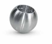
INFO Model 0745 Adj Wall Flange 304 Indoor cOdE d L ø 34.0745.422.S 95 30 42.4 x 2.0 34.0745.426.S 95 30 42.4 x 2.6 34.0745.482.S 100 35 48.3 x 2.0 34.0745.486.S 100 35 48.3 x 2.6 Model 0745 Adj Wall Flange 316’s’ Outdoor cOdE d L ø 36.0745.422.S 95 30 42.4 x 2.0 36.0745.426.S 95 30 42.4 x 2.6 36.0745.482.S 100 35 48.3 x 2.0 36.0745.486.S 100 35 48.3 x 2.6 Model 0750 Ball End 304 Indoor cOdE L ø 34.0750.012.S 17.5 12 Model 0750 Ball End 316’s’ Outdoor cOdE L ø 36.0750.012.S 17.5 12 Model 0760 Support 304 Indoor cOdE ø BOLT 34.0760.420.S 42.4 FF-29 Model 0760 Support 316’s’ Outdoor cOdE ø BOLT 36.0760.420.S 42.4 FF-29 FrEE FIXINGS Model 0748 Slim Wall Flange 304 Indoor cOdE d L ø 34.0748.420.S 50 35 42.4 34.0748.480.S 56 35 48.3 Model 0748 Slim Wall Flange 316’s’ Outdoor cOdE d L ø 36.0748.420.S 50 35 42.4 36.0748.480.S 56 35 48.3 ACCESSOrIES PAGE 131 Stainless Steel cleaner 500 ml 10.9020.000.A P PROTECTED DESIGN P PROTECTED DESIGN www.fastechandrails.co.uk www.fastechandrails.co.uk
34.0810.482.S
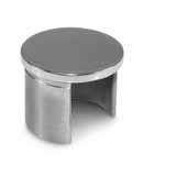
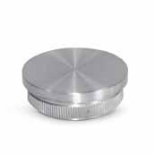
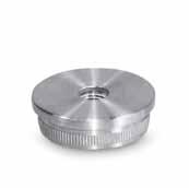
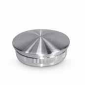
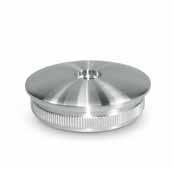
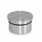
84 85 ENDCAPS Model 0800 Flat End Cap 304 Indoor cOdE ø 34.0800.422.S 42.4 x 2.0 34.0800.426.S 42.4 x 2.6 34.0800.482.S 48.3 x 2.0 34.0800.486.S 48.3 x 2.6 Model 0800 Flat End Cap 316’s’ Outdoor cOdE ø 36.0800.422.S 42.4 x 2.0 36.0800.426.S 42.4 x 2.6 36.0800.482.S 48.3 x 2.0 36.0800.486.S 48.3 x 2.6 Model 0810 raised End Cap 304 Indoor cOdE ø 34.0810.422.S 42.4 x 2.0 34.0810.426.S 42.4 x 2.6
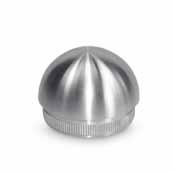
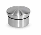
48.3 x 2.0 34.0810.486.S 48.3 x 2.6 Model 0810 raised End Cap 316’s’ Outdoor cOdE ø 36.0810.422.S 42.4 x 2.0 36.0810.426.S 42.4 x 2.6 36.0810.482.S 48.3 x 2.0 36.0810.486.S 48.3 x 2.6 Model 0801 Flat End Cap 304 Indoor cOdE ø 34.0801.422.S 42.4 x 2.0 34.0801.426.S 42.4 x 2.6 34.0801.482.S 48.3 x 2.0 34.0801.486.S 48.3 x 2.6 Model 0801 Flat End Cap 316’s’ Outdoor cOdE ø 36.0801.422.S 42.4 x 2.0 36.0801.426.S 42.4 x 2.6 36.0801.482.S 48.3 x 2.0 36.0801.486.S 48.3 x 2.6 Model 0811 raised End Cap 304 Indoor cOdE ø 34.0811.422.S 42.4 x 2.0 34.0811.426.S 42.4 x 2.6 34.0811.482.S 48.3 x 2.0 34.0811.486.S 48.3 x 2.6 Model 0811 raised End Cap 316’s’ Outdoor cOdE ø 36.0811.422.S 42.4 x 2.0 36.0811.426.S 42.4 x 2.6 36.0811.482.S 48.3 x 2.0 36.0811.486.S 48.3 x 2.6 INFO ACCESSOrIES PAGE 131 Stain remover 500 ml 10.9030.000.A ENDCAPS Model 0820 Domed End Cap 304 Indoor cOdE L ø 34.0820.422.S 21 42.4 x 2.0 34.0820.426.S 21 42.4 x 2.6 34.0820.482.S 24 48.3 x 2.0 34.0820.486.S 24 48.3 x 2.6 Model 0820 Domed End Cap 316’s’ Outdoor cOdE L ø 36.0820.422.S 21 42.4 x 2.0 36.0820.426.S 21 42.4 x 2.6 36.0820.482.S 24 48.3 x 2.0 36.0820.486.S 24 48.3 x 2.6 Model 0860 raised End Cap 304 Indoor cOdE L ø 34.0860.016.S 4 16 x 1.0 34.0860.422.S 9 42.4 x 2.0 34.0860.426.S 9 42.4 x 2.6 34.0860.482.S 10 48.3 x 2.0 34.0860.486.S 10 48.3 x 2.6 Model 0860 raised End Cap 316’s’ Outdoor cOdE L ø 36.0860.016.S 4 16 x 1.0 36.0860.422.S 9 42.4 x 2.0 36.0860.426.S 9 42.4 x 2.6 36.0860.482.S 10 48.3 x 2.0 36.0860.486.S 10 48.3 x 2.6 Model 0850 Flat End Cap 304 Indoor cOdE ø 34.0850.422.S 42.4 x 2.0 34.0850.426.S 42.4 x 2.6 34.0850.482.S 48.3 x 2.0 34.0850.486.S 48.3 x 2.6 Model 0850 Flat End Cap 316’s’ Outdoor cOdE ø 36.0850.422.S 42.4 x 2.0 36.0850.426.S 42.4 x 2.6 36.0850.482.S 48.3 x 2.0 36.0850.486.S 48.3 x 2.6 ACCESSOrIES PAGE 131 Stainless Steel cleaner 500 ml 10.9020.000.A ACCESSOrIES PAGE 131 Glue 50 ml 10.9010.000.A www.fastechandrails.co.uk www.fastechandrails.co.uk
86 87 SIDE FIX BrACKETS Model 1000 Side Fix Bracket 304 Indoor cOdE d ø 34.1000.420.S 70 42.4 34.1000.480.S 70 48.3 Model 1000 Side Fix Bracket 316’s’ Outdoor cOdE d ø 36.1000.420.S 70 42.4 36.1000.480.S 70 48.3 Model 1010 Side Fix Bracket 304 Indoor cOdE ø 34.1010.420.S 42.4 34.1010.480.S 48.3 Model 1010 Side Fix Bracket 316’s’ Outdoor cOdE ø 36.1010.420.S 42.4 36.1010.480.S 48.3 Model 1030 Corner Bracket 304 Indoor cOdE ø 34.1030.420.S 42.4 34.1030.480.S 48.3 Model 1030 Corner Bracket 316’s’ Outdoor cOdE ø 36.1030.420.S 42.4 36.1030.480.S 48.3 Model 1020 Side Fix Bracket 304 Indoor cOdE ø 34.1020.420.S 42.4 34.1020.480.S 48.3 Model 1020 Side Fix Bracket 316’s’ Outdoor cOdE ø 36.1020.420.S 42.4 36.1020.480.S 48.3 Model 1040 Cleats 304 Indoor cOdE ø L 34.1040.420.S 42.4 50 34.1040.480.S 48.3 55 Model 1040 Cleats 316’s’ Outdoor cOdE ø L 36.1040.420.S 42.4 50 36.1040.480.S 48.3 55 SIDE FIX BrACKETS Model 1050 In-Line Brackets 304 Indoor cOdE d L ø 34.1050.420.S 75 85 42.4 34.1050.480.S 80 85 48.3 Model 1050 In-Line Brackets 316’s’ Outdoor cOdE d L ø 36.1050.420.S 75 85 42.4 36.1050.480.S 80 85 48.3 Model 1060 In-Line Brackets 304 Indoor cOdE ø L 34.1060.420.S 42.4 110 34.1060.480.S 48.3 105 Model 1060 In-Line Brackets 316’s’ Outdoor cOdE ø L 36.1060.420.S 42.4 110 36.1060.480.S 48.3 105 www.fastechandrails.co.uk www.fastechandrails.co.uk
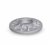
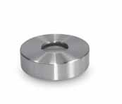
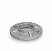
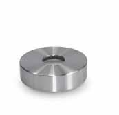
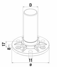
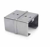
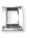
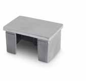
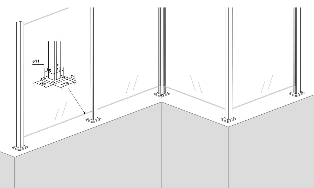
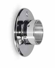
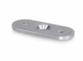
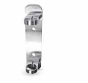
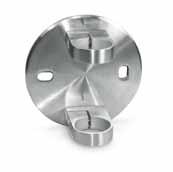
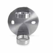
88 89 WELDED BASES/COVErS Model 1100 3 Hole Base 304 Indoor cOdE d B ø 34.1100.420. r 105 80 42.4 34.1100.480. r 115 90 48.3 Model 1100 3 Hole Base 316’s’ Outdoor cOdE d B ø 36.1100.420. r 105 80 42.4 36.1100.480. r 115 90 48.3 Model 1101 Base Cover 304 Indoor cOdE d ø 34.1101.420.S 110 42.4 34.1101.480.S 120 48.3 Model 1101 Base Cover 316 Outdoor cOdE d ø 36.1101.420.S 110 42.4 36.1101.480.S 120 48.3 WELDED/GLUED BASES Model 1110 2 Hole Base 304 Indoor cOdE d B ø 34.1110.420. r 100 75 42.4 34.1110.480. r 100 85 48.3 Model 1110 2 Hole Base 316’s’ Outdoor cOdE d B ø 36.1110.420. r 100 75 42.4 36.1110.480. r 100 85 48.3 Model 1120 2 Hole Base 304 Indoor cOdE d ø 34.1120.420. r 120 42.4 34.1120.480. r 120 48.3 Model 1120 2 Hole Base 316’s’ Outdoor cOdE d ø 36.1120.420. r 120 42.4 36.1120.480. r 120 48.3 Model 1111 Base Cover 304 Indoor cOdE d ø 34.1111.420.S 105 42.4 34.1111.480.S 105 48.3 Model 1111 Base Cover 316 Outdoor cOdE d ø 36.1111.420.S 105 42.4 36.1111.480.S 105 48.3 Model 1121 Base Cover 304 Indoor cOdE d ø 34.1121.420.S 125 42.4 34.1121.480.S 125 48.3 Model 1121 Base Cover 316 Outdoor cOdE d ø 36.1121.420.S 125 42.4 36.1121.480.S 125 48.3 90 Model 1105 Glue In Base 304 Indoor cOdE d ø 34.1105.422. r 42.4 x 2.0 105 34.1105.426. r 42.4 x 2.6 105 34.1105.482. r 48.3 x 2.0 115 34.1105.486. r 48.3 x 2.6 115 USE MOdEL 1101 BASE cOVErS Model 1105 Glue In Base 316’s’ Outdoor cOdE d ø 36.1105.422. r 42.4 x 2.0 105 36.1105.426. r 42.4 x 2.6 105 36.1105.482. r 48.3 x 2.0 115 36.1105.486. r 48.3 x 2.6 115 USE MOdEL 1101 BASE cOVErS Model 1150 Adj Base 304 Indoor cOdE ø L1 L2 34.1150.426.S 42.4 x 2.6 30 80 34.1150.486.S 48.3 x 2.6 35 84 Model 1150 Adj Base 316’s’ Outdoor cOdE ø L1 L2 36.1150.426.S 42.4 x 2.6 30 80 36.1150.486.S 48.3 x 2.6 35 84 Model 1200 Weldable Base 304 Indoor cOdE d ø 34.1200.420.S 100 42.4 34.1200.480.S 100 48.3 Model 1210 Weldable Base 304 Indoor cOdE d ø 34.1210.420.S 120 42.4 34.1210.480.S 120 48.3 Model 1280 Spigot Cover 304 Indoor cOdE ø 34.1280.420.S 42.4 34.1280.480.S 48.3 Model 1280 Spigot Cover 316 Outdoor cOdE ø 36.1280.420.S 42.4 36.1280.480.S 48.3 Model 1250 Square Plate 304 Indoor cOdE L H ø 34.1250.120.S 120 80 11 B www.fastechandrails.co.uk www.fastechandrails.co.uk


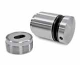
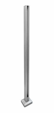
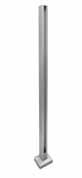
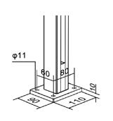
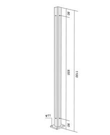
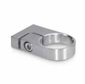
90 91 Model 1520 2 Hole Base 304 Indoor cOdE ø 34.1520.426.S 42.4 x 2.6 34.1520.486.S 48.3 x 2.6 Model 1520 2 Hole Base 316 Outdoor cOdE ø 36.1520.426.S 42.4 x 2.6 36.1520.486.S 48.3 x 2.6 Model 1530 2 Hole Base 304 Indoor cOdE ø 34.1530.426.S 42.4 x 2.6 34.1530.486.S 48.3 x 2.6 Model 1530 2 Hole Base 316 Outdoor cOdE ø 36.1530.426.S 42.4 x 2.6 36.1530.486.S 48.3 x 2.6 8 980 16 100 Ø 12 80 Ø 8 980 16 120 90 Ø Ø 12 CLAMP FIX BASES/POSTS POSTS Model 1310 Clamp Fix Top 304 Indoor cOdE ø 34.1310.420.S 42.4 34.1310.480.S 48.3 Model 1310 Clamp Fix Top 316’s’ Outdoor cOdE ø 36.1310.420.S 42.4 36.1310.480.S 48.3 Model 1710 Clamp Fix Post 304 Indoor cOdE ø 34.1710.426.S 42.4 x 2.6 34.1710.486.S 48.3 x 2.6 Model 1320 Clamp Fix Bottom 304 Indoor cOdE 34.1320.060.S Model 1320 Clamp Fix Bottom 316’s’ Outdoor cOdE 36.1320.060.S Model 1300 Threaded Insert 304 Indoor cOdE ø 34.1300.426. r 42.4 x 2.6 34.1300.486. r 48.3 x 2.6 Model 1300 Threaded Insert 316’s’ Outdoor cOdE ø 36.1300.426. r 42.4 x 2.6 36.1300.486. r 48.3 x 2.6 Model 1321 Top Washer cOdE 10.1321.059.P Model 1311 Bottom Washer cOdE 10.1311.059.P Ø 60 30 - 80 Ø Ø 18 10 98 0 ø18 INFO 8 L1 L2 980 17 D Ø 11 B Ø L1 L2 980 17 D 11 Ø Model 1620 Mid Post 304 Indoor cOdE d ø B L1 L2 34.1620.426. r 105 42.4 x 2.6 80 195 120 34.1620.486. r 115 48.3 x 2.6 90 195 120 Model 1620 Mid Post 316 Outdoor cOdE d ø B L1 L2 36.1620.426.S 105 42.4 x 2.6 80 195 120 36.1620.486.S 115 48.3 x 2.6 90 195 120 Model 1630 Corner Post 304 Indoor cOdE d ø B L1 L2 34.1630.426. r 105 42.4 x 2.6 80 195 120 34.1630.486. r 115 48.3 x 2.6 90 195 120 Model 1630 Corner Post 316 Outdoor cOdE d ø B L1 L2 36.1630.426.S 105 42.4 x 2.6 80 195 120 36.1630.486.S 115 48.3 x 2.6 90 195 120 W W 90º 90º 8 980 17 D Ø 11 B Ø L1 L2 980 17 D Ø 11 B Ø 8 Model 1510 Post 304 Indoor cOdE d ø B 34.1510.426.S 105 42.4 x 2.6 80 34.1510.486.S 115 48.3 x 2.6 90 Model 1510 Post 316 Outdoor cOdE d ø B 36.1510.426.S 105 42.4 x 2.6 80 36.1510.486.S 115 48.3 x 2.6 90 Model 1610 End Post 304 Indoor cOdE d ø B L1 L2 34.1610.426. r 105 42.4 x 2.6 80 195 120 34.1610.486. r 115 48.3 x 2.6 90 195 120 Model 1610 End Post 316 Outdoor cOdE d ø B L1 L2 36.1610.426.S 105 42.4 x 2.6 80 195 120 36.1610.486.S 115 48.3 x 2.6 90 195 120 W W www.fastechandrails.co.uk www.fastechandrails.co.uk

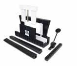
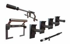
Pre-Assembled Posts Are now here
Quick, Easy, convenient, Affordable
Ready to go posts inc: Welded base
Base Cover
Glass Clamps
Stem Connector (Supplied Loose)
Reduce Manufacture time + Speed up installation time
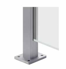
For the ease of installation Fastec now offers an alternative range of Pre-Assembled Balustrade Posts saving time and costs by allowing the installer to focus on the installation rather than the manufacture.
92 93 PrE-ASSEMBLED POSTS Ø Ø PCB W W Ø Ø Ø PCB Ø Ø PCB W 90º 90º
End Post 316 Outdoor cOdE ø Pre-Assembled End Post 42.4 x 2.0 1 Mid Post 316 Outdoor cOdE ø Pre-Assembled Mid Post 42.4 x 2.0 1 Corner Post 316 Outdoor cOdE ø Pre-Assembled c orner Post 42.4 x 2.0 1 www.fastechandrails.co.uk www.fastechandrails.co.uk
work Fastec workworksmarter,faster, These new posts use substituted products away from the
Fastec range.

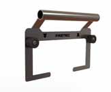
94 95 CrOSSBAr HOLDErS Model 2010/2012 Mid Crossbar 304 Indoor cOdE ø BOLT 34.2010.000.S 10 FF-15 34.2012.000.S 12 FF-15 Model 2012 Mid Crossbar 316 Outdoor cOdE ø BOLT 36.2012.000.S 12 FF-16 Model 2212 End Crossbar 304 Indoor cOdE ø BOLT 34.2212.000.S 12 FF-15 Model 2212 End Crossbar 316 Outdoor cOdE ø BOLT 36.2212.000.S 12 FF-16 Model 2312 End Crossbar 304 Indoor cOdE ø BOLT 34.2312.000.S 12 FF-15 Model 2312 End Crossbar 316 Outdoor cOdE ø BOLT 36.2312.000.S 12 FF-16 Model 2110/2112 Connector Crossbar 304 Indoor cOdE ø BOLT 34.2110.000.S 10 FF-15 34.2112.000.S 12 FF-15 Model 2012 Connector Crossbar 316 Outdoor cOdE ø BOLT 36.2112.000.S 12 FF-16 Model 2010/2012 Mid Crossbar 304 Indoor cOdE d ø BOLT 34.2010.420.S 42.4 10 FF-15 34.2012.420.S 42.4 12 FF-15 34.2012.480.S 48.3 12 FF-15 Model 2010/2012 Mid Crossbar 316 Outdoor cOdE d ø BOLT 36.2012.420.S 42.4 12 FF-16 36.2012.480.S 48.3 12 FF-16 Model 2110/2112 Connector 304 Indoor cOdE d ø BOLT 34.2110.420.S 42.4 10 FF-15 34.2112.420.S 42.4 12 FF-15 34.2112.480.S 48.3 12 FF-15 Model 2110/2112 Connector 316 Outdoor cOdE d ø BOLT 36.2112.420.S 42.4 12 FF-16 36.2112.480.S 48.3 12 FF-16 FrEE FIXINGS FrEE FIXINGS FrEE FIXINGS FrEE FIXINGS FrEE FIXINGS FrEE FIXINGS CrOSSBAr HOLDErS Model 2416 Mid Crossbar 304 Indoor cOdE ø BOLT 34.2416.000.S 16 FF-15 Model 2416 Mid Crossbar 316 Outdoor cOdE ø BOLT 36.2416.000.S 16 FF-16 Model 2812 In-line Crossbar 304 Indoor cOdE ø BOLT 34.2812.420.S 42.4 FF-15 34.2812.480.S 48.3 FF-15 Model 2912 Adj In-line Crossbar 304 Indoor cOdE ø BOLT 34.2912.420.S 42.4 FF-15 34.2912.480.S 48.3 FF-15 FrEE FIXINGS FrEE FIXINGS FrEE FIXINGS FrEE FIXINGS FrEE FIXINGS FrEE FIXINGS Model 2212 End Crossbar 304 Indoor cOdE d ø BOLT 34.2212.420.S 42.4 12 FF-15 34.2212.480.S 48.3 12 FF-15 Model 2212 End Crossbar 316 Outdoor cOdE d ø BOLT 36.2212.420.S 42.4 12 FF-16 36.2212.480.S 48.3 12 FF-16 Model 2312 End Crossbar 304 Indoor cOdE d ø BOLT 34.2312.420.S 42.4 12 FF-15 34.2312.480.S 48.3 12 FF-15 Model 2212 End Crossbar 316 Outdoor cOdE d ø BOLT 36.2312.420.S 42.4 12 FF-16 36.2312.480.S 48.3 12 FF-16 Model 2416 Mid Crossbar 304 Indoor cOdE d ø BOLT 34.2416.420.S 42.4 16 FF-19 34.2416.480.S 48.3 16 FF-19 Model 2416 Mid Crossbar 316 Outdoor cOdE d ø BOLT 36.2416.420.S 42.4 16 FF-20 36.2416.480.S 48.3 16 FF-20 www.fastechandrails.co.uk www.fastechandrails.co.uk
97 MIRROR POLISHED MIrrOr POLISHED Model 0110 Stem 304 Indoor cOdE d L ø BOLT 34.0110.426.M 42.4 x 2.6 80 42.4 FF-10 34.0110.486.M 48.3 x 2.6 80 48.3 FF-10 Model 0110 Stem 316’s’ Outdoor cOdE d L ø BOLT 36.0110.426.M 42.4 x 2.6 80 42.4 FF-11 36.0110.486.M 48.3 x 2.6 80 48.3 FF-11 Model 0115 Adj Stem 304 Indoor cOdE d L ø BOLT 34.0115.426.M 42.4 x 2.6 80 42.4 FF-10 34.0115.486.M 48.3 x 2.6 80 48.3 FF-10 Model 0115 Adj Stem 316’s’ Outdoor cOdE d L ø BOLT 36.0115.426.M 42.4 x 2.6 80 42.4 FF-11 36.0115.486.M 48.3 x 2.6 80 48.3 FF-11 FrEE FIXINGS FrEE FIXINGS Model 0130 90º Stem 304 Indoor cOdE d L ø BOLT 34.0130.426.M 42.4 x 2.6 80 42.4 FF-10 34.0130.486.M 48.3 x 2.6 80 48.3 FF-10 Model 0130 90º Stem 316’s’ Outdoor cOdE d L ø BOLT 36.0130.426.M 42.4 x 2.6 80 42.4 FF-11 36.0130.486.M 48.3 x 2.6 80 48.3 FF-11 FrEE FIXINGS Model 0521 Handrail Bracket 304 Indoor cOdE ø BOLT 34.0521.420.M 42.4 FF-10 34.0521.480.M 48.3 FF-10 Model 0521 Handrail Bracket 316’s’ Outdoor cOdE ø BOLT 36.0521.420.M 42.4 FF-11 36.0521.480.M 48.3 FF-11 FrEE FIXINGS Model 0440 Handrail Bracket 304 Indoor cOdE ø BOLT 34.0440.420.M 42.4 FF-10 34.0440.480.M 48.3 FF-10 Model 0440 Handrail Bracket 316’s’ Outdoor cOdE ø BOLT 36.0440.420.M 42.4 FF-11 36.0440.480.M 48.3 FF-11 Model 0445 Adj Handrail Bracket 304 Indoor cOdE ø BOLT 34.0445.420.M 42.4 FF-10 34.0445.480.M 48.3 FF-10 Model 0445 Adj Handrail Bracket 316’s’ Outdoor cOdE ø BOLT 36.0445.420.M 42.4 FF-11 36.0445.480.M 48.3 FF-11 FrEE FIXINGS FrEE FIXINGS www.fastechandrails.co.uk
98 99 MIrrOr POLISHED Model 0610 90º Elbow 304 Indoor cOdE L ø 34.0610.426.M 30 42.4 x 2.6 34.0610.486.M 35 48.3 x 2.6 Model 0610 90º Elbow 316’s’ Outdoor cOdE L ø 36.0610.426.M 30 42.4 x 2.6 36.0610.486.M 35 48.3 x 2.6 Model 0640 Adj Elbow 304 Indoor cOdE L ø 34.0640.426.M 27 42.4 x 2.6 34.0640.486.M 30 48.3 x 2.6 Model 0640 Adj Elbow 316’s’ Outdoor cOdE L ø 36.0640.426.M 27 42.4 x 2.6 36.0640.486.M 30 48.3 x 2.6 Model 0720 Connector 304 Indoor cOdE ø 34.0720.426.M 42.4 x 2.6 34.0720.486.M 48.3 x 2.6 Model 0720 Connector 316’s’ Outdoor cOdE ø 36.0720.426.M 42.4 x 2.6 36.0720.486.M 48.3 x 2.6 Model 0731 Adaptor 304 Indoor cOdE d ø BOLT 34.0731.426.M 42.4 x 2.6 42.4 FF-45 34.0731.486.M 48.3 x 2.6 48.3 FF-45 Model 0731 Adaptor 316’s’ Outdoor cOdE d ø BOLT 36.0731.426.M 42.4 x 2.6 42.4 FF-46 36.0731.486.M 48.3 x 2.6 48.3 FF-46 Model 0740 Wall Flange 304 Indoor cOdE d L ø BOLT 34.0740.420.M 95 30 42.4 FF-6 34.0740.480.M 100 35 48.3 FF-6 Model 0740 Wall Flange 316’s’ Outdoor cOdE d L ø BOLT 36.0740.420.M 95 30 42.4 FF-7 36.0740.480.M 100 35 48.3 FF-7 FrEE FIXINGS Model 0860 raised End Cap 304 Indoor cOdE L ø 34.0860.426.M 9 42.4 x 2.6 34.0860.486.M 10 48.3 x 2.6 3Model 0860 raised End Cap 316’s’ Outdoor cOdE L ø 36.0860.426.M 9 42.4 x 2.6 36.0860.486.M 10 48.3 x 2.6 MIrrOr POLISHED Model 1010 Side Fix Bracket 304 Indoor cOdE ø 34.1010.420.M 42.4 34.1010.480.M 48.3 Model 1010 Side Fix Bracket 316’s’ Outdoor cOdE ø 36.1010.420.M 42.4 36.1010.480.M 48.3 8 980 17 D Ø 11 B Ø Model 1510 Post 304 Indoor cOdE d ø B 34.1510.426.M 105 42.4 x 2.6 80 34.1510.486.M 115 48.3 x 2.6 90 Model 1510 Post 316 Outdoor cOdE d ø B 36.1510.426.M 105 42.4 x 2.6 80 36.1510.486.M 115 48.3 x 2.6 90 Model 1101 Base Cover 304 Indoor cOdE d ø 34.1101.420.M 110 42.4 34.1101.480.M 120 48.3 Model 1101 Base Cover 316 Outdoor cOdE d ø 36.1101.420.M 110 42.4 36.1101.480.M 120 48.3 42.4mm Tube 304 Indoor cOdE L T(MM 34.1900.426.M 6000 mm 2.6 34.1910.426.M 3000 mm 2.6 42.4mm Tube 316 Outdoor cOdE L T(MM 36.1900.426.M 6000 mm 2.6 36.1910.426.M 3000 mm 2.6 48.3mm Tube 304 Indoor cOdE L T(MM) 34.1900.486.M 6000 mm 2.6 34.1910.486.M 3000 mm 2.6 48.3mm Tube 316 Outdoor cOdE L T(MM) 36.1900.486.M 6000 mm 2.6 36.1910.486.M 3000 mm 2.6 Ø 42.4 L T Ø 48.3 T FrEE FIXINGS Model 32 Glass Clamps 304 Indoor cOdE SEE PAGE 101 FO r d ETA i LS Model 32 316’s’ Outdoor cOdE SEE PAGE 101 FO r d ETA i LS ø ø ø ø www.fastechandrails.co.uk www.fastechandrails.co.uk
101
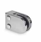
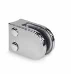
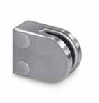
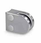
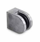
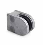
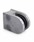
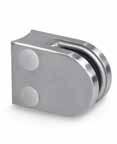
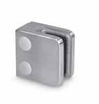
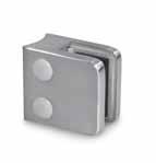
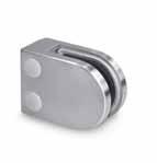
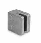
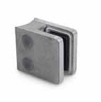
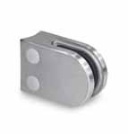
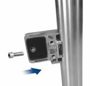
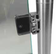
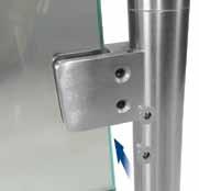
INFO GLASS CLAMPS STAiNLESS/ZiNTEc Model 30 radiused Glass Clamp 304 Indoor cOdE ø G (MM) BOLT 34.3006.420.S 42.4 6 FF-45 34.3008.420.S 42.4 8 FF-45 Model 30 radiused Glass Clamp 316’s’ Outdoor cOdE ø G (MM) BOLT 36.3006.420.S 42.4 6 FF-46 36.3008.420.S 42.4 8 FF-46 Model 30 radiused Glass Clamp ZINTEC Indoor cOdE ø G (MM) BOLT 20.3006.420. r 42.4 6 FF-47 20.3008.420. r 42.4 8 FF-47 20.3006.420.S 42.4 6 FF-47 20.3008.420.S 42.4 8 FF-47 Model 30 Flat Glass Clamp 304 Indoor cOdE G MM) BOLT 34.3006.000.S 6 FF-45 34.3008.000.S 8 FF-45 Model 30 Flat Glass Clamp 316’s’ Outdoor cOdE G MM) BOLT 36.3006.000.S 6 FF-46 36.3008.000.S 8 FF-46 Model 30 Flat Glass Clamp ZINTEC Indoor cOdE G MM) BOLT 20.3006.000. r 6 FF-47 20.3008.000. r 8 FF-47 20.3006.000.S 6 FF-47 20.3008.000.S 8 FF-47 FrEE FIXINGS FrEE FIXINGS FrEE FIXINGS FrEE FIXINGS ACCESSOrIES PAGE 131 Glass cleaner 500 ml 10.9020.000.A ZINTEC Finishes r = raw Finish S = Satin Effect www.fastechandrails.co.uk
GLASS CLAMPS
34.3208.000.S 8 FF-45
34.3210.000.S 10 FF-45
34.3212.000.S 12 FF-45
34.3209.000.S 8.76 FF-45
36.3206.000.S 6 FF-46
36.3208.000.S 8 FF-46
36.3210.000.S 10 FF-46
36.3212.000.S 12 FF-46
36.3209.000.S 8.76 FF-46
36.3244.000.S 9.52 FF-46
36.3211.000.S 10.76 FF-46
36.3254.000.S 11.52 FF-46
36.3213.000.S 12.76 FF-46
102 103 GLASS CLAMPS STAiNLESS/ZiNTEc Model 31 radiused Glass Clamp 304 Indoor cOdE ø G (MM) BOLT 34.3106.420.S 42.4 6 FF-45 34.3108.420.S 42.4 8 FF-45 34.3110.420.S 42.4 10 FF-45 34.3109.420.S 42.4 8.76 FF-45 34.3144.420.S 42.4 9.52 FF-45 Model 31 radiused Glass Clamp 316’s’ Outdoor cOdE ø G (MM) BOLT 36.3106.420.S 42.4 6 FF-46 36.3108.420.S 42.4 8 FF-46 36.3110.420.S 42.4 10 FF-46 36.3109.420.S 42.4 8.76 FF-46 36.3144.420.S 42.4 9.52 FF-46 Model 31 radiused Glass Clamp ZINTEC Indoor cOdE ø G (MM) BOLT 20.3106.420. r 42.4 6 FF-47 20.3108.420. r 42.4 8 FF-47 20.3110.420. r 42.4 10 FF-47 20.3106.420.S 42.4 6 FF-47 20.3108.420.S 42.4 8 FF-47 20.3110.420.S 42.4 10 FF-47 Model 31 Flat Glass Clamp 304 Indoor cOdE G (MM BOLT 34.3106.000.S 6 FF-45 34.3108.000.S 8 FF-45 34.3110.000.S 10 FF-45 34.3109.000.S 8.76 FF-45 34.3144.000.S 9.52 FF-45 Model 31 Flat Glass Clamp 316’s’ Outdoor cOdE G (MM) BOLT 36.3106.000.S 6 FF-46 36.3108.000.S 8 FF-46 36.3110.000.S 10 FF-46 36.3109.000.S 8.76 FF-46 36.3144.000.S 9.52 FF-46 Model 31 Flat Glass Clamp ZINTEC Indoor cOdE G (MM BOLT 20.3106.000. r 6 FF-47 20.3108.000. r 8 FF-47 20.3110.000. r 10 FF-47 20.3106.000.S 6 FF-47 20.3108.000.S 8 FF-47 20.3110.000.S 10 FF-47 FrEE FIXINGS FrEE FIXINGS FrEE FIXINGS FrEE FIXINGS INFO GLASS CLAMPS STAiNLESS Model 32 radiused Glass Clamp 304 Indoor cOdE ø G (MM) BOLT 34.3206.420.S 42.4 6 FF-45 34.3208.420.S 42.4 8 FF-45 34.3210.420.S 42.4 10 FF-45 34.3212.420.S 42.4 12 FF-45 34.3209.420.S 42.4 8.76 FF-45 34.3244.420.S 42.4 9.52 FF-45 34.3211.420.S 42.4 10.76 FF-45 34.3254.420.S 42.4 11.52 FF-45 34.3213.420.S 42.4 12.76 FF-45 34.3206.480.S 48.3 6 FF-45 34.3208.480.S 48.3 8 FF-45 34.3210.480.S 48.3 10 FF-45 34.3212.480.S 48.3 12 FF-45 34.3209.480.S 48.3 8.76 FF-45 34.3244.480.S 48.3 9.52 FF-45 34.3211.480.S 48.3 10.76 FF-45 34.3254.480.S 48.3 11.52 FF-45 34.3213.480.S 48.3 12.76 FF-45 Model 32 radiused Glass Clamp 316’s’ Outdoor cOdE ø G (MM) BOLT 36.3206.420.S 42.4 6 FF-46 36.3208.420.S 42.4 8 FF-46 36.3210.420.S 42.4 10 FF-46 36.3212.420.S 42.4 12 FF-46 36.3209.420.S 42.4 8.76 FF-46 36.3244.420.S 42.4 9.52 FF-46 36.3211.420.S 42.4 10.76 FF-46 36.3254.420.S 42.4 11.52 FF-46 36.3213.420.S 42.4 12.76 FF-46 36.3206.480.S 48.3 6 FF-46 36.3208.480.S 48.3 8 FF-46 36.3210.480.S 48.3 10 FF-46 36.3212.480.S 48.3 12 FF-46 36.3209.480.S 48.3 8.76 FF-46 36.3244.480.S 48.3 9.52 FF-46 36.3211.480.S 48.3 10.76 FF-46 36.3254.480.S 48.3 11.52 FF-46 36.3213.480.S 48.3 12.76 FF-46 Model
304 Indoor cOdE
MM)
32 Flat Glass Clamp
G
BOLT
34.3206.000.S 6 FF-45
34.3211.000.S
FF-45
Model
316’s’ Outdoor cOdE
MM) BOLT
34.3244.000.S 9.52 FF-45
10.76 FF-45 34.3254.000.S 11.52
34.3213.000.S 12.76 FF-45
32 Flat Glass Clamp
G
FrEE FIXINGS FrEE FIXINGS www.fastechandrails.co.uk www.fastechandrails.co.uk
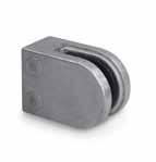
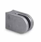
20.3210.000.S
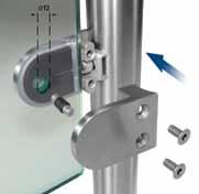
104 105 GLASS CLAMPS ZiNTEc Model 32 Flat - Mirror 304 Indoor cOdE G (MM BOLT 34.3206.000.M 6 FF-45 34.3208.000.M 8 FF-45 34.3210.000.M 10 FF-45 34.3212.000.M 12 FF-45 34.3209.000.M 8.76 FF-45 34.3244.000.M 9.52 FF-45 34.3211.000.M 10.76 FF-45 34.3254.000.M 11.52 FF-45 34.3213.000.M 12.76 FF-45 Model 31 Flat - Mirror 316’s Outdoor cOdE G (MM BOLT 36.3206.000.M 6 FF-46 36.3208.000.M 8 FF-46 36.3210.000.M 10 FF-46 36.3212.000.M 12 FF-45 36.3209.000.M 8.76 FF-46 36.3244.000.M 9.52 FF-45 36.3211.000.M 10.76 FF-45 36.3254.000.M 11.52 FF-45 36.3213.000.M 12.76 FF-46 FrEE FIXINGS FrEE FIXINGS INFO INFO ZINTEC Finishes r = raw Finish S = Satin Effect PLEASE NOTE: Pins MUST be used in all side fix installations Model 32 radiused - Mirror 304 Indoor cOdE ø G (MM) BOLT 34.3206.420.M 42.4 6 FF-45 34.3208.420.M 42.4 8 FF-45 34.3210.420.M 42.4 10 FF-45 34.3212.420.M 42.4 12 FF-45 34.3209.420.M 42.4 8.76 FF-45 34.3244.420.M 42.4 9.52 FF-45 34.3211.420.M 42.4 10.76 FF-45 34.3254.420.M 42.4 11.52 FF-45 34.3213.420.M 42.4 12.76 FF-45 34.3206.480.M 48.3 6 FF-45 34.3208.480.M 48.3 8 FF-45 34.3210.480.M 48.3 10 FF-45 34.3212.480.M 48.3 12 FF-45 34.3209.480.M 48.3 8.76 FF-45 34.3244.480.M 48.3 9.52 FF-45 34.3211.480.M 48.3 10.76 FF-45 34.3254.480.M 48.3 11.52 FF-45 34.3213.480.M 48.3 12.76 FF-45 Model 32 radiused - Mirror 316’s Outdoor cOdE ø G (MM) BOLT 36.3206.420.M 42.4 6 FF-46 36.3208.420.M 42.4 8 FF-46 36.3210.420.M 42.4 10 FF-46 36.3212.420.M 42.4 12 FF-46 36.3209.420.M 42.4 8.76 FF-46 36.3244.420.M 42.4 9.52 FF-46 36.3211.420.M 42.4 10.76 FF-46 36.3254.420.M 42.4 11.52 FF-46 36.3213.420.M 42.4 12.76 FF-46 36.3206.480.M 48.3 6 FF-46 36.3208.480.M 48.3 8 FF-46 36.3210.480.M 48.3 10 FF-46 36.3212.480.M 48.3 12 FF-46 36.3209.480.M 48.3 8.76 FF-46 36.3244.480.M 48.3 9.52 FF-46 36.3211.480.M 48.3 10.76 FF-46 36.3254.480.M 48.3 11.52 FF-46 36.3213.480.M 48.3 12.76 FF-46 GLASS CLAMPS STAiNLESS/MirrOr POLiSHEd Model 32 radiused Glass Clamp ZINTEC Indoor cOdE ø G (MM) BOLT 20.3206.420. r 42.4 6 FF-47 20.3208.420. r 42.4 8 FF-47 20.3210.420. r 42.4 10 FF-47 20.3206.480. r 48.3 6 FF-47 20.3208.480. r 48.3 8 FF-47 20.3210.480. r 48.3 10 FF-47 20.3206.420.S 42.4 6 FF-47 20.3208.420.S 42.4 8 FF-47 20.3210.420.S 42.4 10 FF-47
48.3 6 FF-47
48.3 8 FF-47 20.3210.480.S 48.3 10 FF-47 FrEE FIXINGS Model 32 Flat Glass Clamp ZINTEC Indoor cOdE G (MM BOLT 20.3206.000. r 6 FF-47 20.3208.000. r 8 FF-47 20.3210.000. r 10 FF-47 20.3206.000.S 6 FF-47 20.3208.000.S 8 FF-47
10 FF-47 FrEE FIXINGS www.fastechandrails.co.uk www.fastechandrails.co.uk
20.3206.480.S
20.3208.480.S
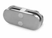
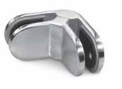
106 107 Model 32.100 In-Line 304 Indoor cOdE G (MM 34.3206.100.S 6 34.3208.100.S 8 34.3210.100.S 10 34.3209.100.S 8.76 34.3244.100.S 9.52 Model 32.100 In-Line 316’s’ Outdoor cOdE G (MM) 36.3206.100.S 6 36.3208.100.S 8 36.3210.100.S 10 36.3209.100.S 8.76 36.3244.100.S 9.52 Model 33.100 Inline 304 Indoor cOdE G (MM 34.3312.100.S 12 34.3315.100.S 15 34.3311.100.S 10.76 34.3354.100.S 11.52
12.76
13.52 Model 33.100 Inline 316’s’ Outdoor cOdE G (MM) 36.3312.100.S 12 36.3315.100.S 15 36.3311.100.S 10.76 36.3354.100.S 11.52 36.3313.100.S 12.76 36.3364.100.S 13.52 Model 33.200 90º Corner 304 Indoor cOdE G MM) 34.3312.200.S 12 34.3315.200.S 15 34.3311.200.S 10.76 34.3354.200.S 11.52 34.3313.200.S 12.76 34.3364.200.S 13.52 Model 33.200 90º Corner 316’s’ Outdoor cOdE G MM) 36.3312.200.S 12 36.3315.200.S 15 36.3311.200.S 10.76 36.3354.200.S 11.52 36.3313.200.S 12.76 36.3364.200.S 13.52 Model 32.200 90º Corner 304 Indoor cOdE G MM) 34.3206.200.S 6 34.3208.200.S 8 34.3210.200.S 10 34.3209.200.S 8.76 34.3244.200.S 9.52 Model 32.200 90º Corner 316’s’ Outdoor cOdE G MM) 36.3206.200.S 6 36.3208.200.S 8 36.3210.200.S 10 36.3209.200.S 8.76 36.3244.200.S 9.52 Model 33 radiused Glass Clamp ZINTEC Indoor cOdE ø G (MM) BOLT 20.3312.420. r 42.4 12 FF-47 20.3312.480. r 48.3 12 FF-47 20.3312.420.S 42.4 12 FF-47 20.3312.480.S 48.3 12 FF-47 Model 33 Flat Glass Clamp ZINTEC Indoor cOdE G MM) BOLT 20.3312.000. r 12 FF-47 20.3312.000.S 12 FF-47 FrEE FIXINGS FrEE FIXINGS INFO INFO ZINTEC Finishes r = raw Finish S = Satin Effect GLASS CLAMPS STAiNLESS GLASS CLAMPS ZiNTEc PLEASE NOTE: Pins MUST be used in all side fix installations www.fastechandrails.co.uk www.fastechandrails.co.uk
34.3313.100.S
34.3364.100.S
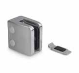
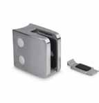
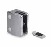
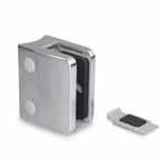
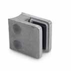
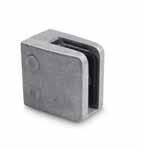
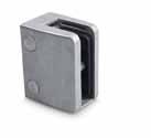
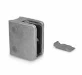
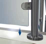
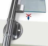
108 109 Model 34 radiused Glass Clamp 304 Indoor cOdE ø G (MM) BOLT 34.3408.420.S 42.4 8 FF-45 34.3410.420.S 42.4 10 FF-45 34.3412.420.S 42.4 12 FF-45 34.3411.420.S 42.4 10.76 FF-45 34.3454.420.S 42.4 11.52 FF-45 34.3413.420.S 42.4 12.76 FF-45 34.3408.480.S 48.3 8 FF-45 34.3410.480.S 48.3 10 FF-45 34.3412.480.S 48.3 12 FF-45 34.3411.480.S 48.3 10.76 FF-45 34.3454.480.S 48.3 11.52 FF-45
48.3 12.76 FF-45 Model 34 radiused Glass Clamp 316’s’ Outdoor cOdE ø G (MM) BOLT 36.3408.420.S 42.4 8 FF-46 36.3410.420.S 42.4 10 FF-46 36.3412.420.S 42.4 12 FF-46 36.3411.420.S 42.4 10.76 FF-46 36.3454.420.S 42.4 11.52 FF-46 36.3413.420.S 42.4 12.76 FF-46 36.3408.480.S 48.3 8 FF-46 36.3410.480.S 48.3 10 FF-46 36.3412.480.S 48.3 12 FF-46 36.3411.480.S 48.3 10.76 FF-46 36.3454.480.S 48.3 11.52 FF-46 36.3413.480.S 48.3 12.76 FF-46 Model 34 Flat Glass Clamp 304 Indoor cOdE G (MM BOLT 34.3408.000.S 8 FF-45 34.3410.000.S 10 FF-45 34.3412.000.S 12 FF-45 34.3411.000.S 10.76 FF-45 34.3454.000.S 11.52 FF-45 34.3413.000.S 12.76 FF-45 Model 34 Flat Glass Clamp 316’s’ Outdoor cOdE G (MM) BOLT 36.3408.000.S 8 FF-46 36.3410.000.S 10 FF-46 36.3412.000.S 12 FF-46 36.3411.000.S 10.76 FF-46 36.3454.000.S 11.52 FF-46 36.3413.000.S 12.76 FF-46 FrEE FIXINGS FrEE FIXINGS Model 34 radiused Glass Clamp ZINTEC Indoor cOdE ø G (MM) BOLT 20.3408.420. r 42.4 8 FF-47 20.3410.420. r 42.4 10 FF-47 20.3412.420. r 42.4 12 FF-47 20.3408.480. r 48.3 8 FF-47 20.3410.480. r 48.3 10 FF-47 20.3412.480. r 48.3 12 FF-47 20.3408.420.S 42.4 8 FF-47 20.3410.420.S 42.4 10 FF-47 20.3412.420.S 42.4 12 FF-47 20.3408.480.S 48.3 8 FF-47 20.3410.480.S 48.3 10 FF-47 20.3412.480.S 48.3 12 FF-47 Model 34 Flat Glass Clamp ZINTEC Indoor cOdE G MM) BOLT 20.3408.000. r 8 FF-47 20.3410.000. r 10 FF-47 20.3412.000. r 12 FF-47 20.3408.000.S 8 FF-47 20.3410.000.S 10 FF-47 20.3412.000.S 12 FF-47 FrEE FIXINGS FrEE FIXINGS Model 35 radiused Glass Clamp 304 Indoor cOdE ø G (MM) BOLT 34.3510.480.S 48.3 10 FF-45 34.3512.480.S 48.3 12 FF-45 34.3515.480.S 48.3 15 FF-45 34.3564.480.S 48.3 13.52 FF-45 34.3517.480.S 48.3 17.52 FF-45 Model 35 radiused Glass Clamp 316’s’ Outdoor cOdE ø G (MM) BOLT 36.3510.480.S 48.3 10 FF-46 36.3512.480.S 48.3 12 FF-46 36.3515.480.S 48.3 15 FF-46 36.3564.480.S 48.3 13.52 FF-46 36.3517.480.S 48.3 17.52 FF-46 Model 35 Flat Glass Clamp 304 Indoor cOdE G MM) BOLT 34.3510.000.S 10 FF-45 34.3512.000.S 12 FF-45 34.3515.000.S 15 FF-45 34.3564.000.S 13.52 FF-45 34.3517.000.S 17.52 FF-45 Model 35 Flat Glass Clamp 316’s’ Outdoor cOdE G MM) BOLT 36.3510.000.S 10 FF-46 36.3512.000.S 12 FF-46 36.3515.000.S 15 FF-46 36.3564.000.S 13.52 FF-46 36.3517.000.S 17.52 FF-46 FrEE FIXINGS FrEE FIXINGS FrEE FIXINGS FrEE FIXINGS Model 35 Flat Glass Clamp ZINTEC Indoor cOdE G MM) BOLT 20.3510.000. r 10 FF-47 20.3512.000. r 12 FF-47 20.3515.000. r 15 FF-47 20.3510.000.S 10 FF-47 20.3512.000.S 12 FF-47 20.3515.000.S 15 FF-47 Model 35 radiused Glass Clamp ZINTEC Indoor cOdE ø G (MM) BOLT 20.3510.480. r 48.3 10 FF-47 20.3512.480. r 48.3 15 FF-47 20.3515.480. r 48.3 15 FF-47 20.3510.480.S 48.3 10 FF-47 20.3512.480.S 48.3 12 FF-47 20.3515.480.S 48.3 15 FF-47 INFO
CLAMPS STAiNLESS/ZiNTEc GLASS CLAMPS STAiNLESS/ZiNTEc www.fastechandrails.co.uk www.fastechandrails.co.uk
34.3413.480.S
GLASS
technical innovationmastery creativity

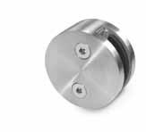
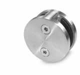
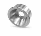
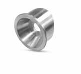
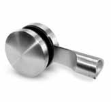
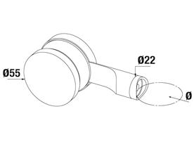
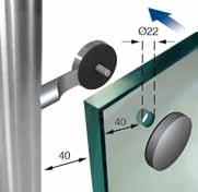
110 111 New Model 39 glass clamps offer a different look and feel to your balustrade design creating a unique installation
GLASS CLAMPS STAiNLESS STEEL Model 38.100 Glass Clamp 304 Indoor cOdE G MM) BOLT 34.3808.100.S 8 FF-45 34.3810.100.S 10 FF-45 34.3812.100.S 12 FF-45 Model 38.100 Glass Clamp 316’s’ Outdoor cOdE G MM) BOLT 36.3808.100.S 8 FF-46 36.3810.100.S 10 FF-46 36.3812.100.S 12 FF-46 Model 38 Adaptor 304 Indoor cOdE 34.3800.000.S Model 38 Adaptor 316’s’ Outdoor cOdE 36.3800.000.S Model 38 Adaptor 304 Indoor cOdE ø 34.3800.420.S 42.4 34.3800.480.S 48.3 Model 38 Adaptor 316’s’ Outdoor cOdE ø 36.3800.420.S 42.4 36.3800.480.S 48.3 Model 38.200 Glass Clamp 304 Indoor cOdE G (MM BOLT 34.3808.200.S 8 FF-45 34.3810.200.S 10 FF-45 34.3812.200.S 12 FF-45 Model 38.200 Glass Clamp 316’s’ Outdoor cOdE G (MM BOLT 36.3808.200.S 8 FF-46 36.3810.200.S 10 FF-46 36.3812.200.S 12 FF-46 FrEE FIXINGS FrEE FIXINGS Model 39 Glass Clamp 304 Indoor cOdE G MM) ø BOLT 34.3900.420.S 9.52-17.52 42.4 FF-15 34.3900.480.S 9.52-17.52 48.3 FF-15 Model 39 Glass Clamp 316’s’ Outdoor cOdE G MM) ø BOLT 36.3900.420.S 9.52-17.52 42.4 FF-16 36.3900.480.S 9.52-17.52 48.3 FF-16 INFO FrEE FIXINGS P PROTECTED DESIGN www.fastechandrails.co.uk www.fastechandrails.co.uk
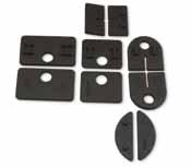
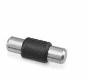
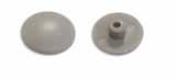
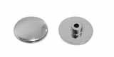
112 113 GLASS CLAMPS rUBBErS Model 30 rubbers (1 No. Pair) cOdE cLAMP G (MM) 40.3006.000. r SS 6 40.3008.000. r SS 8 Model 31 rubbers (1 No. Pair) cOdE cLAMP G (MM) 40.3106.000. r SS 6 40.3108.000. r SS 8 40.3110.000. r SS 10 40.3108.760. r SS 8.76 40.3109.520. r SS 9.52 Model 32 rubbers (1 No. Pair) cOdE cLAMP G (MM) 40.3206.000. r SS 6 40.3208.000. r SS 8 40.3210.000. r SS 10 40.3212.000. r SS 12 40.3208.760. r SS 8.76
r SS 9.52 40.3210.760. r SS 10.76 40.3211.520. r SS 11.52 40.3212.760. r SS 12.76 Model 34 rubbers (1 No. Pair) cOdE cLAMP G (MM) 40.3408.000. r SS 8 40.3410.000. r SS 10 40.3412.000. r SS 12 40.3410.760. r SS 10.76 40.3411.520. r SS 11.52 40.3412.760. r SS 12.76 Model 35 rubbers (1 No. Pair) cOdE cLAMP G (MM) 40.3510.000. r SS 10 40.3512.000. r SS 12 40.3515.000. r SS 15 40.3513.520. r SS 13.52 40.3517.520. r SS 17.52 Model 38.100 rubbers (1 No. Pair) cOdE cLAMP G (MM) 40.3808.000. r SS 8 40.3810.000. r SS 10 40.3812.000. r SS 12 Model 32.100 & 32.200 rubbers (1 No. Set of 4 rubbers) cOdE cLAMP G MM) 42.3206.000. r SS 6 42.3208.000. r SS 8 42.3210.000. r SS 10 42.3208.760. r SS 8.76 42.3209.520. r SS 9.52 Model 33.100 & 33.200 rubbers (1 No. Set of 4 rubbers) cOdE cLAMP G MM) 42.3312.000. r SS 12 42.3315.000. r SS 15 42.3310.760. r SS 10.76 42.3311.520. r SS 11.52 42.3312.760. r SS 12.76 42.3313.520. r SS 13.52 Model 38.200 rubbers (1 No. Set of 4 rubbers) cOdE cLAMP G MM) 42.3808.000. r SS 8 42.3810.000. r SS 10 40.3812.000. r SS 12 To Suit Stainless Steel Glass Clamps To Suit Double Headed Glass Clamps GLASS CLAMPS rUBBErS, PiNS ANd cOVEr cAPS Model 30 rubbers (1 No. Pair) cOdE cLAMP G MM) 41.3006.000. r Zintec 6 41.3008.000. r Zintec 8 Model 31 rubbers (1 No. Pair) cOdE cLAMP G MM) 41.3106.000. r Zintec 6 41.3108.000. r Zintec 8 41.3110.000. r Zintec 10 Model 32 rubbers (1 No. Pair) cOdE cLAMP G MM) 41.3206.000. r Zintec 6 41.3208.00. r Zintec 8 41.3210.000. r Zintec 10 Model 33 rubbers (1 No. Pair) cOdE cLAMP G MM) 41.3312.000. r Zintec 12 Model 34 rubbers (1 No. Pair) cOdE cLAMP G MM) 41.3408.000. r Zintec 8 41.3410.000. r Zintec 10 41.3412.000. r Zintec 12 Model 35 rubbers (1 No. Pair) cOdE cLAMP G MM) 41.3515.000. r Zintec 10 41.3512.000. r Zintec 12 41.3515.000. r Zintec 15 Model 30 Security Pins cOdE 40.4010.030. r Model 32 Security Pins cOdE 40.4010.032. r Model 33 Security Pins cOdE 40.4010.033. r Model 34 Security Pins cOdE 40.4010.035. r To Suit Zintec Glass Clamps Ø 6 Ø 8 L Cover Caps cOdE 40.4020.010.P Cover Caps cOdE 40.4020.010.M www.fastechandrails.co.uk www.fastechandrails.co.uk
40.3209.520.
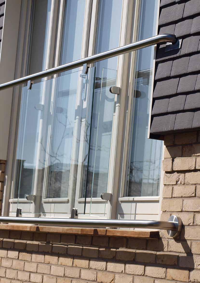
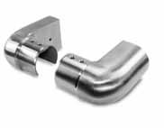
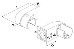
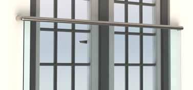
115
BALCONY
BALCONY Model 7000/7100 Handrail 304 Indoor cOdE L ø T U 34.7000.420.S 5000 42.4 24 24 34.7000.480.S 5000 48.3 30 27 34.7000.600.S 5000 60.3 34 34 34.7100.420.S 2500 42.4 24 24 34.7100.480.S 2500 48.3 30 27 34.7100.600.S 2500 60.3 34 34 Model 7000/7100 Handrail 316 Outdoor cOdE L ø T U 36.7000.420.S 5000 42.4 24 24 36.7000.480.S 5000 48.3 30 27 36.7100.420.S 2500 42.4 24 24 36.7100.480.S 2500 48.3 30 27 Model 7042 42.4 mm rubber Set cOdE L U G (MM 40.7042.010. r 5000 24 8-11 40.7042.012. r 5000 24 11.52-13.52 40.7042.015. r 5000 24 15-16.76 40.7042.019. r 5000 24 17.52-19 40.7042.020. r 5000 24 21.52 40.7142.010. r 2500 24 8-11 40.7142.012. r 2500 24 11.52-13.52 40.7142.015. r 2500 24 15-16.76 40.7142.019. r 2500 24 17.52-19 40.7142.020. r 2500 24 21.52 Model 7048 48.3 mm rubber Set cOdE L U G (MM 40.7048.012. r 5000 27 11.52-13.52 40.7048.015. r 5000 27 15-16.76 40.7048.019. r 5000 27 17.52-19 40.7048.020. r 5000 27 21.52 40.7148.012. r 2500 27 11.52-13.52 40.7148.015. r 2500 27 15-16.76 40.7148.019. r 2500 27 17.52-19 40.7148.020. r 2500 27 21.52 Model 4000 Fixing Brackets 316’s’ Outdoor cOdE L ø L1 H 36.4000.420.S 62 42.4 31 42.4 36.4000.480.S 64 48.3 39 48.3 INFO www.fastechandrails.co.uk
JULIET
JULIET
GLASS
CONNECTORS & PANEL HOLDERS
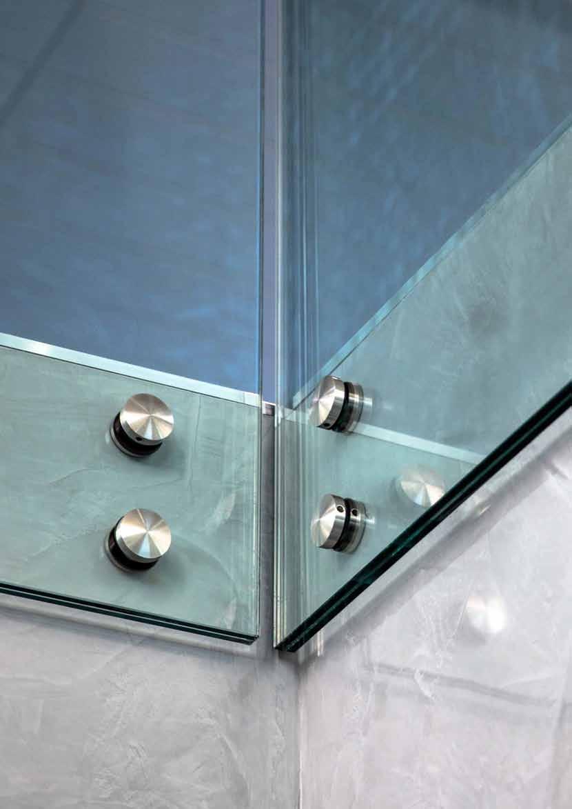
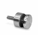
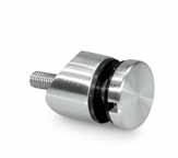
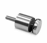
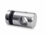
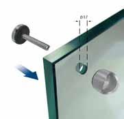
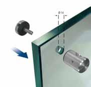
117
Model 4010 Glass Connector 304 Indoor cOdE 34.4010.000.S Model 4010 Glass Connector 316’s’ Outdoor cOdE 36.4010.000.S Model 4010 Glass Connector 304 Indoor cOdE L 34.4010.100.S 30 Model 4020 Glass Connector 304 Indoor cOdE 34.4020.016.S Model 4020 Glass Connector 316’s’ Outdoor cOdE 36.4020.016.S Model 4010 Glass Connector 304 Indoor cOdE ø 34.4010.420.S 42.4 34.4010.480.S 48.3 Model 4010 Glass Connector 316’s’ Outdoor cOdE ø 36.4010.420.S 42.4 36.4010.480.S 48.3 INFO Model: 4010 Model: 4020 www.fastechandrails.co.uk
GLASS CONNECTOrS
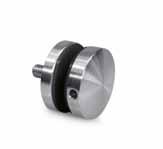
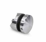
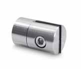
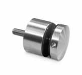
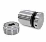
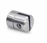
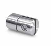
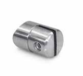
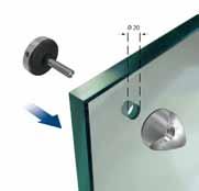

118 119 GLASS CONNECTOrS 8-22 0-10 40 ø 50 11 L ø D Model 4030 Glass Connector 304 Indoor cOdE 34.4030.000.S Model 4030 Glass Connector 316’s’ Outdoor cOdE 36.4030.000.S Model 4030 Glass Connector 304 Indoor cOdE 34.4030.100.S Model 4030 Glass Connector 316’s’ Outdoor cOdE 36.4030.100.S Model 4100 Adj Glass Connector 316’s’ Outdoor cOdE 36.4100.040.S Model 4030 Glass Connector 304 Indoor cOdE ø 34.4030.420.S 42.4 34.4030.480.S 48.3 Model 4030 Glass Connector 316’s’ Outdoor cOdE ø 36.4030.420.S 42.4 36.4030.480.S 48.3 Model 9180 Threaded Insert (10 No.) Zinc Plated cOdE d L ø 20.9180.080.Z M8 23 16 20.9180.102.Z M10 25 18.5 20.9180.104.Z M10 40 18.5 PANEL HOLDErS Model 4500 Panel Holder 304 Indoor cOdE BOLT 34.4500.000.S FF-15 Model 4500 Panel Holder 316’s’ Outdoor cOdE BOLT 36.4500.000.S FF-16 Model 4510 Panel Holder 304 Indoor cOdE BOLT 34.4510.000.S FF-15 Model 4510 Panel Holder 316’s’ Outdoor cOdE BOLT 36.4510.000.S FF-16 Model 4500 Panel Holder 304 Indoor cOdE ø BOLT 34.4500.420.S 42.4 FF-15 34.4500.480.S 48.3 FF-15 Model 4500 Panel Holder 316’s’ Outdoor cOdE ø BOLT 36.4500.420.S 42.4 FF-16 36.4500.480.S 48.3 FF-16 Model 4510 Panel Holder 304 Indoor cOdE ø BOLT 34.4510.420.S 42.4 FF-15 34.4510.480.S 48.3 FF-15 Model 4510 Panel Holder 316’s’ Outdoor cOdE ø BOLT 36.4510.420.S 42.4 FF-16 36.4510.480.S 48.3 FF-16 FrEE FIXINGS FrEE FIXINGS FrEE FIXINGS FrEE FIXINGS ACCESSOrIES PAGE 131 nternal cleaner 500 ml 10.9020.000.A ACCESSOrIES PAGE 131 Glass cleaner 500 ml 10.9020.000.A INFO
www.fastechandrails.co.uk www.fastechandrails.co.uk
Model: 4030 Model: 4100
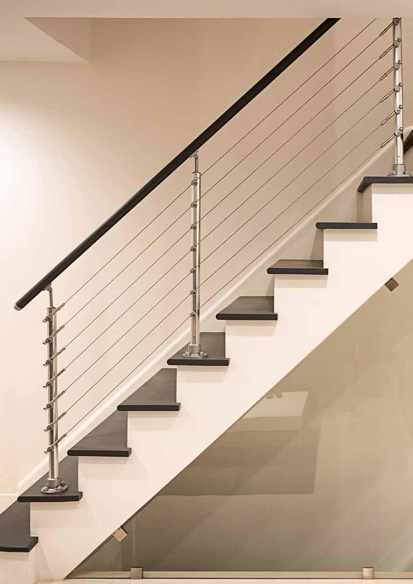
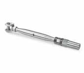
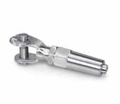
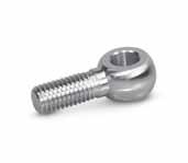
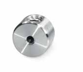
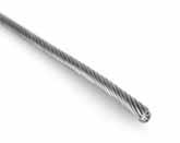
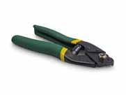
121 WIRE-TEC Ø D L Ø D H L Model 6010 Terminal with Jaw 304 Indoor cOdE cABLE ø d H L 34.6000.003.S 3.2mm 3.2 5 90 155-230 34.6000.006.S 6.0mm 6.0 7 125 200-290 Model 6010 Terminal with Jaw 316 Outdoor cOdE cABLE ø d H U 36.6000.003.S 3.2mm 3.2 5 90 155-230 36.6000.006.S 6.0mm 6.0 7 125 200-290 Model 6010 Terminal with Jaw 304 Indoor cOdE cABLE ø d L 34.6010.003.S 3.2mm 3.2 5 50 34.6010.006.S 6.0mm 6.0 7 70 Model 6010 Terminal with Jaw 316 Outdoor cOdE cABLE ø d U 36.6010.003.S 3.2mm 3.2 5 50 36.6010.006.S 6.0mm 6.0 7 70 Model 6030 Cable Stopper 304 Indoor cOdE cABLE ø d 34.6030.003.S 3.2mm 3.5 18 34.6030.006.S 6.0mm 6.5 20 Model 6030 Cable Stopper 316 Outdoor cOdE cABLE ø d 36.6030.003.S 3.2mm 3.5 18 36.6030.006.S 6.0mm 6.5 20 Model 6020 Eye Bolt 304 Indoor cOdE M d L 34.6020.003.S M6 6.0 19 34.6020.006.S M10 8.0 30 Model 6020 Eye Bolt 316 Outdoor cOdE M d L 36.6020.003.S M6 6.0 19 36.6020.006.S M10 8.0 30 D Ø 12 M D L Model 6203/6206 Cable (1x19) 304 Indoor cOdE ø L 34.6203.010.S 3.2 10M 34.6203.050.S 3.2 50M 34.6203.100.S 3.2 100M 34.6206.010.S 6.0 10M 34.6206.050.S 6.0 50M 34.6206.100.S 6.0 100M Model 6203/6206 Cable (1x19) 316 Outdoor cOdE ø L 36.6203.010.S 3.2 10M 36.6203.050.S 3.2 50M 36.6203.100.S 3.2 100M 36.6203.010.S 6.0 10M 36.6203.050.S 6.0 50M 36.6203.100.S 6.0 100M Ø Model 6350 Cable Cutters cOdE ø 10.6350.000.T 3.2 WIrE-TEC www.fastechandrails.co.uk
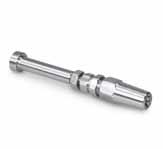
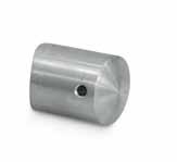
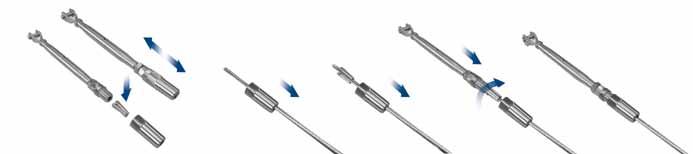
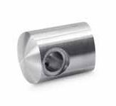
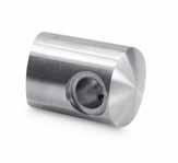
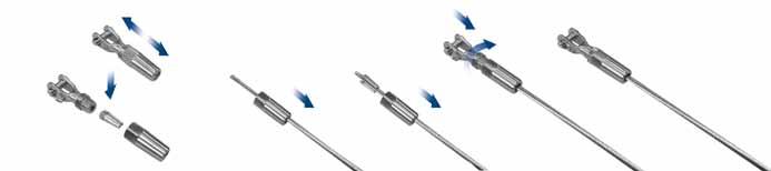
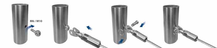
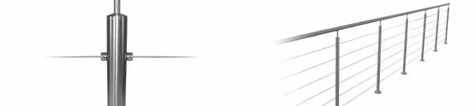
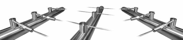
122 123 Ø 3.2 Ø 8 80 - 115 Ø 12 Model 6100 Tensioner with Thread 304 Indoor cOdE cABLE 34.6100.003.S 3.2mm Model 6100 Tensioner with Thread 316 Outdoor cOdE cABLE 36.6100.003.S 3.2mm Model 6130 Crossbar holder for Cable 304 Indoor cOdE cABLE d BOLT 34.6130.420.S 3.2mm 42.4 FF-15 34.6130.480.S 3.2mm 48.3 FF-15 Model 6130 Crossbar holder for Cable 316 Outdoor cOdE cABLE d BOLT 36.6130.420.S 3.2mm 42.4 FF-16 36.6130.480.S 3.2mm 48.3 FF-16 Model 6110 Crossbar holder for Tensioner-Left 304 Indoor cOdE d BOLT 34.6110.420.S 42.4 FF-15 34.6110.480.S 48.3 FF-15 Model 6110 Crossbar holder for Tensioner-Left 316 Outdoor cOdE d BOLT 36.6110.420.S 42.4 FF-16 36.6110.480.S 48.3 FF-16 Model 6110 Crossbar holder for Tensioner-right 304 Indoor cOdE d BOLT 34.6120.420.S 42.4 FF-15 34.6120.480.S 48.3 FF-15 Model 6110 Crossbar holder for Tensioner-right 316 Outdoor cOdE d BOLT 36.6120.420.S 42.4 FF-16 36.6120.480.S 48.3 FF-16 FrEE FIXINGS FrEE FIXINGS FrEE FIXINGS Model 6203 Cable 3.2mm (1x19) 304 Indoor cOdE ø L 34.6203.010.S 3.2 10M 34.6203.050.S 3.2 50M 34.6203.100.S 3.2 100M Model 6203 Cable 3.2mm (1x19) 316 Outdoor cOdE ø L 36.6203.010.S 3.2 10M 36.6203.050.S 3.2 50M 36.6203.100.S 3.2 100M Ø WIrE-TEC INFO INFO INFO INFO INFO WIrE-TEC www.fastechandrails.co.uk www.fastechandrails.co.uk

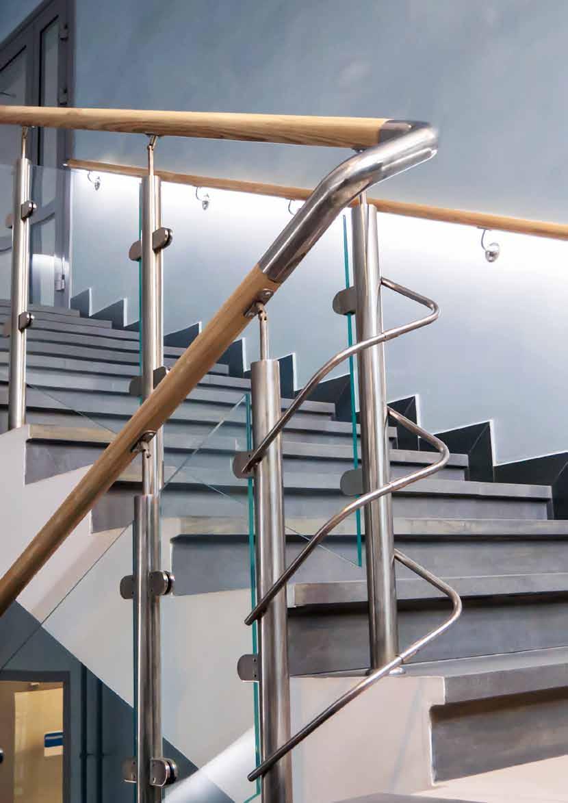


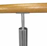
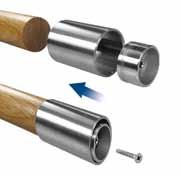
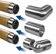
125 TIMBER-TEC Model 8020 Adj Elbow 304 Indoor cOdE ø L BOLT 34.8020.420.S 42 50 FF-6 34.8020.480.S 48 55 FF-6 FrEE FIXINGS FrEE FIXINGS Model 8000 Beech Handrail cOdE ø L 22.8000.420.B 42 2400 22.8000.480.B 48 2400 Model 8000 Oak Handrail cOdE ø L 22.8000.420.O 42 2400 22.8000.480.O 48 2400 INFO TIMBEr-TEC Model 8010 Elbow 304 Indoor cOdE ø L BOLT 34.8010.420.S 42 60 FF-6 34.8010.480.S 48 65 FF-6 www.fastechandrails.co.uk
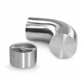
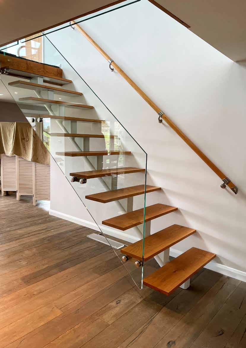
126 Model 8030 return End 304 Indoor cOdE ø L H BOLT 34.8030.420.S 42 70 91 FF-6 34.8030.480.S 48 75 89 FF-6 Model 8040 End Cap 304 Indoor cOdE ø L BOLT 34.8040.420.S 42 30 FF-6 34.8040.480.S 48 35 FF-6 FrEE FIXINGS FrEE FIXINGS FrEE FIXINGS FrEE FIXINGS Model 6400 Aligning Tool cOdE ø 10.6400.420.T 42 10.6400.480.T 48 TIMBEr-TEC Model 8060 Spigot 304 Indoor cOdE ø L BOLT 34.8060.420.S 42 21 FF-6 34.8060.480.S 48 23 FF-6 Model 8050 Connector 304 Indoor cOdE ø L BOLT
42 60 FF-6 34.8050.480.S 48 65 FF-6 www.fastechandrails.co.uk
34.8050.420.S
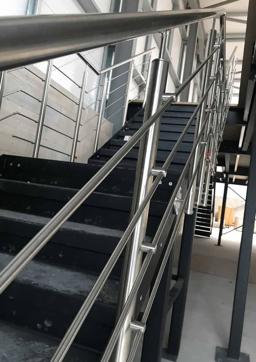
129 ø 10mm Bar 304 Indoor cOdE L 34.1900.010.S 5000mm 34.1910.010.S 2500mm ø 12mm Bar 304 Indoor cOdE L 34.1900.012.S 5000mm 34.1910.012.S 2500mm ø 12mm Bar 316 Outdoor cOdE L 36.1900.012.S 5000mm 36.1910.012.S 2500mm Ø 10 L Ø 12 L ø 16mm Tube 304 Indoor cOdE L T(MM 34.1900.016.S 5000mm 1.0 34.1910.016.S 2500mm 1.0 ø 16mm Tube 316 Outdoor cOdE L T(MM 36.1900.016.S 5000mm 1.0 36.1910.016.S 2500mm 1.0 ø 42.4mm Tube 304 Indoor cOdE L T(MM 34.1900.422.S 6000mm 2.0 34.1900.426.S 6000mm 2.6 34.1910.422.S 3000mm 2.0 34.1910.426.S 3000mm 2.6 ø 42.4mm Tube 316 Outdoor cOdE L T(MM 36.1900.422.S 6000mm 2.0 36.1900.426.S 6000mm 2.6 36.1910.422.S 3000mm 2.0 36.1910.426.S 3000mm 2.6 ø 48.3mm Tube 304 Indoor cOdE L T(MM) 34.1900.482.S 6000mm 2.0 34.1900.486.S 6000mm 2.6 34.1910.482.S 3000mm 2.0 34.1910.486.S 3000mm 2.6 ø 48.3mm Tube 316 Outdoor cOdE L T(MM) 36.1900.482.S 6000mm 2.0 36.1900.486.S 6000mm 2.6 36.1910.482.S 3000mm 2.0 36.1910.486.S 3000mm 2.6 Ø 16 1.0 L Ø 42.4 L T Ø 48.3 T TUBES
www.fastechandrails.co.uk
AND BArS TUBES AND BARS


131 Model 9010 Glue cOdE 10.9010.000.A 50 ml Model 9030 Stain remover cOdE 10.9030.000.A 500 ml Model 9025 Glass Cleaner cOdE 10.9025.000.A 500 ml Model 9020 Stainless Steel Cleaner cOdE 10.9020.000.A 500 ml Model 9027 Stainless Steel & Glass Cleaner Kit cOdE 10.9027.000.A 500 ml Model 9200 ‘C’ Spanner cOdE ø 10.9200.025.T 25-28 10.9200.030.T 30-32 10.9200.045.T 45-50 10.9200.058.T 58-62 Model 9400 Tube Cutter & replacement Blades (2 Pack) cOdE ø 10.9400.000.T Tube cutter 6-6.5mm 10.9400.100.T replacement blades Model 9300 Allen Key Set cOdE ø 10.9300.000.T 1.5, 2.0, 3.0, 4.0, 5.0, 6.0, 8.0 SAVE 25%
ACCESSORIES www.fastechandrails.co.uk
ACCESSOrIES
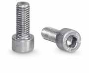
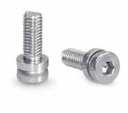
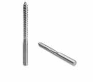
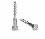
The
solution FrEE FIxInGS
132 133 M8 Ø 13 28 L D D Model 9101 Adj Socket Headed Cap Screw (20 No.) 304 cOdE ø d H L 34.9101.820. r 13 M8 8 20 Model 9101 Adj Socket Headed Cap Screw (20 No.) 316 cOdE ø d H L 36.9101.820. r 13 M8 8 20 Model 9101 Adj Socket Headed Cap Screw (20 No.) Zinc Plated cOdE ø d H L 20.9101.820.Z 13 M8 8 20 Model 9120 Button Head Screw (20 No.) 304 cOdE d L BOLT 34.9120.512. r M5 12 FF-10 Model 9120 Button Head Screw (20 No.) 316 cOdE d L BOLT 36.9120.512. r M5 12 FF-11 L D H Ø Model 9100 Socket Headed Cap Screw (20 No.) 304 cOdE ø d H L BOLT 34.9100.820. r 13 M8 8 20 FF-45 34.9100.835. r 13 M8 8 35 FF-29 Model 9100 Socket Headed Cap Screw (20 No.) 316 cOdE ø d H L BOLT 36.9100.820. r 13 M8 8 20 FF-46 36.9100.835. r 13 M8 8 35 FF-30 Model 9100 Socket Headed Cap Screw (20 No.) Zinc Plated cOdE ø d H L BOLT 20.9100.835.Z 13 M8 8 20 FF-47 L D Model 9110 Counter Sunk Screw (20 No.) 304 cOdE d ø BOLT 34.9110.516. r M5 16 FF-12 34.9110.616. r M6 16 FF-48 34.9110.620. r M6 20 FF-15 34.9110.825. r M8 25 FF-19 34.9110.840. r M8 40 FF-21 Model 9110 Counter Sunk Screw (20 No.) 316 cOdE d ø BOLT 36.9110.516. r M5 16 FF-13 36.9110.616. r M6 16 FF-49 36.9110.620. r M6 20 FF-16 36.9110.825. r M8 25 FF-20 36.9110.840. r M8 40 FF-22 ACCESSOrIES Model 9160 Dual Thread Screw (20 No.) 304 Indoor cOdE d L 34.9160.850. r M8 50 Model 9160 Dual Thread Screw (20 No.) 316 Outdoor cOdE d L 36.9160.850. r M8 50 Model 9165 Coach Screw (20 No.) 304 Indoor cOdE d L 34.9165.855. r M8 55 Model 9165 Coach Screw (20 No.) 316 Outdoor cOdE d L 36.9165.855. r M8 55 L ø D Model 9180 Threaded Insert (10 No.) Zinc Plated Indoor cOdE d L ø 20.9180.080.Z M8 23 16 20.9180.102.Z M10 25 18.5 20.9180.104.Z M10 40 18.5
need
individual fittings
information
bolts
screws supplied. Whilst we supply the bolts and screws for fastening the system together we do not supply the fasteners to secure the fittings to floors and walls, if you are unsure which fittings are supplied please refer to the information stated on each fitting. FrEE FIXINGS
FREE FIXINGS offer.
ACCESSOrIES Model 9170 Screw (20 No.) 304 Indoor cOdE L BOLT 34.9170.840. r 40 FF-6 Model 9170 Screw (20 No.) 316 Outdoor cOdE L BOLT 36.9170.840. r 40 FF-6 www.fastechandrails.co.uk www.fastechandrails.co.uk
complete
We listened to your needs and have responded by providing all the fixings you
to assemble your Fastec Handrail System. All the bolts and screws for each fitting will be supplied with your order to allow you to concentrate on assembling and building your system together saving you both time and money. Please refer to the
for
and details on the
and
Look out for the
Please call for further details.
s u P erior corrosion
r esis Tance
G316 ' s '


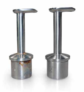
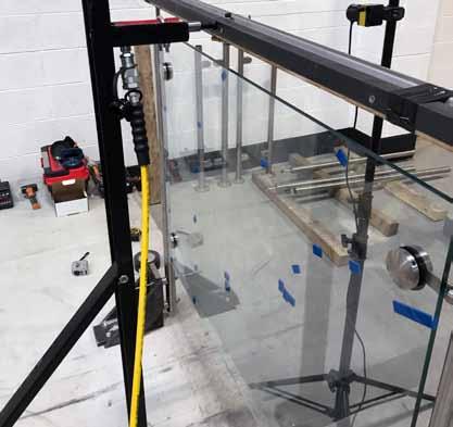
i ns TallaT ion i ns T ruc T ions
s a F e T y Tes T in G
138-143
156
160-163 137
145-155
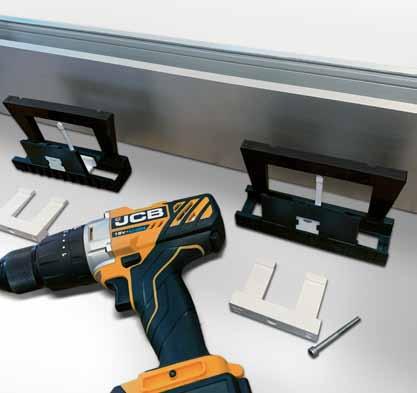
c are a nd m ain T enance en Q uiry s hee T s


c us Tomer i n F ormaT ion
158-159
G316‘s’ G316
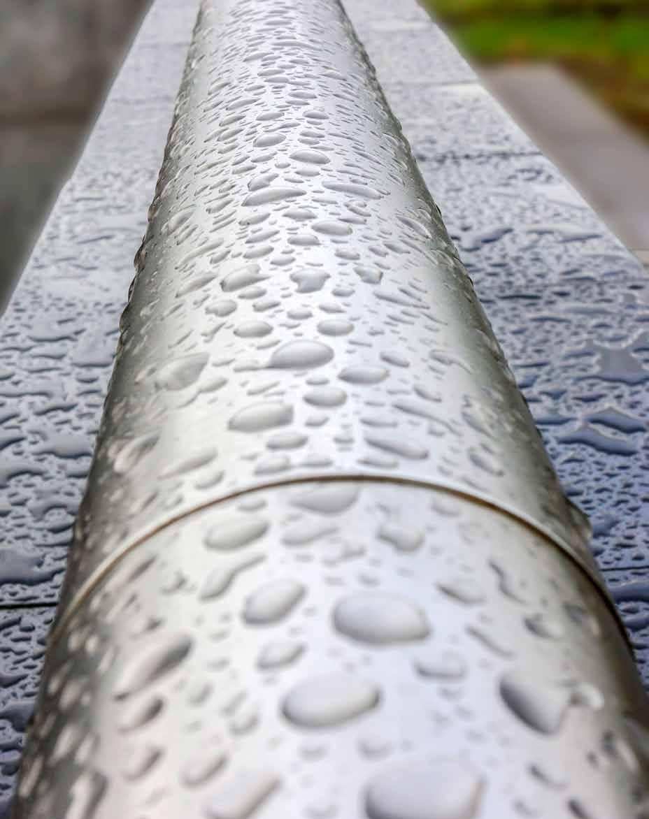
achieving a superior corrosion resistance with G316‘s’
Although stainless steel has an inherent corrosion resistance it cannot be called ‘stain free’. In certain conditions it will stain and discolour.
To offer our customers a superior product and greater value for money, all G316 Fastec handrail fittings are manufactured using grade 2205 which has increased levels of ‘chromium’, ‘Molybdenum’ & ‘Nickel’, above the maximum percentage stated for G316 offering greater corrosion resistance.
We call this superior grade G316‘s’ (‘s’ means superior). This higher grade offers substantially more corrosion resistance than standard G316, providing greater peace of mind, lower maintenance and less cleaning.


Look for the G316's' logo against our products to see which items are manufactured from 2205.
proven superiority
Sheffield Testing Laboratories Ltd have carried out stringent tests to compare the performance of G316 and G316‘s’ under rigorous salt spray testing. The G316‘s’ fitting outperformed the standard grade G316 fitting, showing no sign of staining over the same test period.
in addition to its unrivalled aesthetic appeal, Fastec G316‘s’ products offer unmatched durability, long life and low maintenance, providing a robust, extra corrosion-resistant solution for a wide range of applications. Your installation will maintain its ‘as new’ appearance with minimal attention.
Our G316’s’ fittings offer superior corrosion resistance.
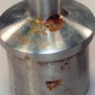
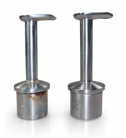
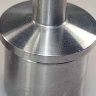
137
G316‘s’ G316
Fastec Handrail Systems


Has your balustrade been tested to BS 6180 ‘Barriers in and about buildings’?
Fastec has established the needs of our customers and has recognised that most handrail systems on the market today have not been tested to ensure they meet British Standard side loading criteria.
the fastec response
For your absolute peace of mind, and to create confidence in your installation for you and your customer we have commissioned extensive testing by independent engineers to establish exactly which design, tube size and thickness, upright centres and fittings will be safest for your installation.
The test results show actual ‘as installed’ results. Please see the following tables for guidance Full test report and Test certificates available to download from www.fastechandrails.co.uk

safety
first
Fastec Handrail Systems 139 SAFETY TESTING
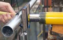


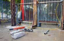

System 4

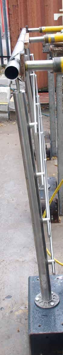
BS 6180: Table 2 LOAD (KN/m) CATEGOrY PASSED 0.22 B&E (iii) ✓ 0.36 A (i), B&E (iv) ✓ 0.74 A (ii), B&E (v), c3 (viii), (ix) ✓ 1.5 c (vi), c1/c (vii), c5 (x), d (xiii), F/G (xiv), F/G (xv) ✓ 3.0 c (x), xi X SYSTEM 1 - SIDE FIX BrACKET - MODEL 1010 48.3 x 2.6mm Diameter Posts Fastec Code S/S Baluster Tube diameter (mm) 48.3x2.6 34.1900.486.S S/S Hand rail diameter (mm) 48.3x2.0 34.1900.482.S Handrail Height (mm) 1100 Baluster Post Spacing (mm) 1300 Mounting Type Side Bracket 34.1010.480.S No. of Fixing Bolts Per Post M12 Handrail connection Stem 34.0110.486.S nfill Type Glass Panel 10mm Glass clamps 4 Per Panel 34.3210.480.S DEFLECTION BEYOND ALLOWABLE LIMIT OCCUrrED AT A LOAD OF 2.0KN/m SYSTEM 1 – SIDE FIX BrACKET - MODEL 1010 42.4 x 2.6mm Diameter Posts Fastec Code S/S Baluster Tube diameter (mm) 42.4x2.6 34.1900.426.S S/S Hand rail diameter (mm) 42.4x2.0 34.1900.422.S Handrail Height (mm) 1100 Baluster Post Spacing (mm) 1300 Mounting Type Side Bracket 34.1010.420.S No. of Fixing Bolts Per Post M12 Handrail connection Stem 34.0110.426.S nfill Type Glass Panel 10mm Glass clamps 4 Per Panel 34.3210.420.S DEFLECTION BEYOND ALLOWABLE LIMIT OCCUrrED AT A LOAD OF 1.9KN/m SYSTEM 2 – BASE PLATE - MODEL 1100 42.4 x 2.6mm Diameter Posts Fastec Code S/S Baluster Tube diameter (mm) 42.4x2.6 34.1900.426.S S/S Hand rail diameter (mm) 42.4x2.0 34.1900.422.S Handrail Height (mm) 1100 Baluster Post Spacing (mm) 1300 Mounting Type Flange Base 34.1100.420.r No. of Fixing Bolts Per Post M10 Handrail connection Stem 34.0110.426.S nfill Type Glass Panel 10mm Glass clamps 4 Per Panel 34.3210.420.S DEFLECTION BEYOND ALLOWABLE LIMIT OCCUrrED AT A LOAD OF 2.25KN/m BS 6180: Table 2 LOAD (KN/m) CATEGOrY PASSED 0.22 B&E (iii) ✓ 0.36 A (i), B&E (iv) ✓ 0.74 A (ii), B&E (v), c3 (viii), (ix) ✓ 1.5 c (vi), c1/c (vii), c5 (x), d (xiii), F/G (xiv), F/G (xv) ✓ 3.0 c (x), xi X SYSTEM 2 – BASE PLATE - MODEL 1100 48.3 x 2.6mm Diameter Posts Fastec Code S/S Baluster Tube diameter (mm) 48.3x2.6 34.1900486.S S/S Hand rail diameter (mm) 48.3x2.0 34.1900.482.S Handrail Height (mm) 1100 Baluster Post Spacing (mm) 1300 Mounting Type Flange Base 34.1100.480.r No. of Fixing Bolts Per Post M10 Handrail connection Stem 34.0110.486.S nfill Type Glass Panel 10mm Glass clamps 4 Per Panel 34.3210.480.S DEFLECTION BEYOND ALLOWABLE LIMIT OCCUrrED AT A LOAD OF 2.4KN/m System 1 - Side Mounted Balustrade Testing in accordance with BS 6180 System 2 - Surface Mounted Balustrade Testing in accordance with BS 6180 Fastec Handrail Systems 140 BS 6180: Table 2 LOAD (KN/m) CATEGOrY PASSED 0.22 B&E (iii) ✓ 0.36 A (i), B&E (iv) ✓ 0.74 A (ii), B&E (v), c3 (viii), (ix) ✓ 1.5 (vi), c1/c (vii), c5 (x), d (xiii), F/G (xiv), F/G (xv) ✓ 3.0 c5 (x), xi X SYSTEM 5 – BASE PLATE + ADAPTOr 48.3 2.6mm Diameter Posts Fastec Code S/S Baluster Tube diameter (mm) 48.3x2.6 34.1900.486.S S/S Hand rail diameter (mm) 48.3x2.0 34.1900.482.S Handrail Height (mm) 1100 Baluster Post Spacing (mm) 1300 Mounting Type Flange Base 34.1100.480.r No. of Fixing Bolts Per Post M10 Handrail connection Glued connector 34.0731.486.S nfill Type Glass Panel 10mm Glass lamps 4 Per Panel 34.3210.480.S DEFLECTION BEYOND ALLOWABLE LIMIT OCCUrrED AT A LOAD OF 2.25KN/m SYSTEM 5 – BASE PLATE + ADAPTOr 42.4 x 2.6mm Diameter Posts Fastec Code S/S Baluster Tube diameter (mm) 42.4x2.6 34.1900.426.S S/S Hand rail diameter (mm) 42.4x2.0 34.1900.422.S Handrail Height (mm) 1100 Baluster Post Spacing (mm) 1300 Mounting Type Flange Base 34.1100.420.r No. of Fixing Bolts Per Post M10 Handrail connection connector 34.0731.426.S nfill Type Glass Panel 10mm Glass lamps 4 Per Panel 34.3210.420.S DEFLECTION BEYOND ALLOWABLE LIMIT OCCUrrED AT A LOAD OF 2.0KN/m
test results
System 3 - Surface Mounted Balustrade Testing in accordance with BS 6180
System 5 - Surface Mounted Balustrade Testing in accordance with BS 6180
- Surface Mounted Balustrade Testing in accordance with BS 6180 Fastec Handrail Systems 141 SYSTEM 3 – BASE PLATE - MODEL 1110 42.4 x 2.6mm Diameter Posts Fastec Code S/S Baluster Tube diameter (mm) 42.4x2.6 13.1900.426.S S/S Hand rail diameter (mm) 42.4x2.0 13.1900.422.S Handrail Height (mm) 1100 Baluster Post Spacing (mm) 1300 Mounting Type Flange Base 34.1110.420.r No. of Fixing Bolts Per Post M10 Handrail connection Stem 34.0110.426.S nfill Type Glass Panel 10mm Glass lamps 4 Per Panel 34.3210.420.S DEFLECTION BEYOND ALLOWABLE LIMIT OCCUrrED AT A LOAD OF 1.9KN/m SYSTEM 3 – BASE PLATE - MODEL 1110 48.3 2.6mm Diameter Posts Fastec Code S/S Baluster Tube diameter (mm) 48.3x2.6 13.1900.486.S S/S Hand rail diameter (mm) 48.3x2.0 13.1900.482.S Handrail Height (mm) 1100 Baluster Post Spacing (mm) 1300 Mounting Type Flange Base 34.1110.480.r No. of Fixing Bolts Per Post M10 Handrail connection Stem 34.0110.486.S nfill Type Glass Panel 10mm Glass lamps 4 Per Panel 34.3210.480.S DEFLECTION BEYOND ALLOWABLE LIMIT OCCUrrED AT A LOAD OF 2.2KN/m BS 6180: Table 2 LOAD (KN/m) CATEGOrY PASSED 0.22 B&E (iii) ✓ 0.36 A (i), B&E (iv) ✓ 0.74 A (ii), B&E (v), c3 (viii), (ix) ✓ 1.5 (vi), c1/c (vii), c5 (x), d (xiii), F/G (xiv), F/G (xv) ✓ 3.0 c5 (x), xi X BS 6180: Table 2 LOAD (KN/m) CATEGOrY PASSED 0.22 B&E (iii) ✓ 0.36 A (i), B&E (iv) ✓ 0.74 A (ii), B&E (v), c3 (viii), (ix) ✓ 1.5 (vi), c1/c (vii), c5 (x), d (xiii), F/G (xiv), F/G (xv) ✓ 3.0 c5 (x), xi X SYSTEM 4 – BASE PLATE - MODEL 1120 42.4 x 2.6mm Diameter Posts Fastec Code S/S Baluster Tube diameter (mm) 42.4x2.6 34.1900.426.S S/S Hand rail diameter (mm) 42.4x2.0 34.1900.422.S Handrail Height (mm) 1100 Baluster Post Spacing (mm) 1300 Mounting Type Flange Base 34.1120.420.r No. of Fixing Bolts Per Post M10 Handrail connection Stem 34.0110.426.S nfill Type Glass Panel 10mm Glass lamps 4 Per Panel 34.3210.420.S DEFLECTION BEYOND ALLOWABLE LIMIT OCCUrrED AT A LOAD OF 2.05KN/m SYSTEM 4 – BASE PLATE - MODEL 1120 48.3 2.6mm Diameter Posts Fastec Code S/S Baluster Tube diameter (mm) 48.3x2.6 34.1900.486.S S/S Hand rail diameter (mm) 48.3x2.0 34.1900.482.S Handrail Height (mm) 1100 Baluster Post Spacing (mm) 1300 Mounting Type Flange Base 34.1120.480.r No. of Fixing Bolts Per Post M10 Handrail connection Stem 34.0110.486.S nfill Type Glass Panel 10mm Glass lamps 4 Per Panel 34.3210.480.S DEFLECTION BEYOND ALLOWABLE LIMIT OCCUrrED AT A LOAD OF 2.3KN/m
BS 6180: Table 2 LOAD (KN/m) CATEGOrY PASSED 0.22 B&E (iii) ✓ 0.36 A (i), B&E (iv) ✓ 0.74 A (ii), B&E (v), c3 (viii), (ix) ✓ 1.5 c (vi), c1/c (vii), c5 (x), d (xiii), F/G (xiv), F/G (xv) X 3.0 c (x), xi X SYSTEM 8 - SIDE FIX BrACKET - MODEL 1050 42.4 x 2.6mm Diameter Posts Fastec Code S/S Baluster Tube diameter (mm) 48.3x2.6 34.1900.486.S S/S Hand rail diameter (mm) 48.3x2.0 34.1900.482.S Handrail Height (mm) 1100 Baluster Post Spacing (mm) 1300 Mounting Type Side Bracket 34.1050.480.S No. of Fixing Bolts Per Post M10 Handrail connection Stem 34.0110.486.S nfill Type Glass Panel 10mm Glass clamps 4 Per Panel 34.3210.480.S DEFLECTION AT 0.74KN/m LOAD rEACHED 21.94mm SYSTEM 8 – SIDE FIX BrACKET - MODEL 1050 42.4 x 2.0mm Diameter Posts Fastec Code S/S Baluster Tube diameter (mm) 42.4x2.6 34.1900.426.S S/S Hand rail diameter (mm) 42.4x2.0 34.1900.422.S Handrail Height (mm) 1100 Baluster Post Spacing (mm) 1300 Mounting Type Side Bracket 34.1050.420.S No. of Fixing Bolts Per Post M10 Handrail connection Stem 34.0110.426.S nfill Type Glass Panel 10mm Glass clamps 4 Per Panel 34.3210.420.S DEFLECTION AT 0.74KN/m LOAD rEACHED 19.55mm System 8 - Side Mounted Balustrade Testing in accordance with BS 6180 Fastec Handrail Systems 142 BS 6180: Table 2 LOAD (KN/m) CATEGOrY PASSED 0.22 B&E (iii) ✓ 0.36 A (i), B&E (iv) ✓ 0.74 A (ii), B&E (v), c3 (viii), (ix) ✓ 1.5 (vi), c1/c (vii), c5 (x), d (xiii), F/G (xiv), F/G (xv) X 3.0 c5 (x), xi X BS 6180: Table 2 LOAD (KN/m) CATEGOrY PASSED 0.22 B&E (iii) ✓ 0.36 A (i), B&E (iv) ✓ 0.74 A (ii), B&E (v), c3 (viii), (ix) ✓ 1.5 (vi), c1/c (vii), c5 (x), d (xiii), F/G (xiv), F/G (xv) X 3.0 c5 (x), xi X BS 6180: Table 2 LOAD (KN/m) CATEGOrY PASSED 0.22 B&E (iii) ✓ 0.36 A (i), B&E (iv) ✓ 0.74 A (ii), B&E (v), c3 (viii), (ix) ✓ 1.5 (vi), c1/c (vii), c5 (x), d (xiii), F/G (xiv), F/G (xv) X 3.0 c5 (x), xi X SYSTEM 9 – GLUED BASE PLATE 48.3 2.6mm Diameter Posts Fastec Code S/S Baluster Tube diameter (mm) 48.3x2.6 34.1900486.S S/S Hand rail diameter (mm) 48.3x2.0 34.1900.482.S Handrail Height (mm) 1100 Baluster Post Spacing (mm) 1300 Mounting Type Flange Base 34.1105.486.r No. of Fixing Bolts Per Post M10 Handrail connection Stem 34.0110.486.S nfill Type Glass Panel 10mm Glass lamps 4 Per Panel 34.3210.480.S DEFLECTION AT 0.74KN/m LOAD rEACHED 17.94mm SYSTEM 11 – POST ONLY SYSTEM 48.3 2.0mm Diameter Posts Fastec Code S/S Post Tube diameter (mm) 48.3x2.0 13.1900.482.S Post Height (mm) 1100 Baluster Post Spacing (mm) 1200 Mounting Type Flange Base 34.1100.480.r No. of Fixing Bolts Per Post M10 nfill Type Glass Panel 10mm Glass lamps 4 Per Panel 34.3210.480.S DEFLECTION AT 0.74KN/m LOAD rEACHED 17.12mm SYSTEM 12 – SIDE FIX BrACKET – MODEL 1060 48.3 2.6mm Diameter Posts Fastec Code S/S Baluster Tube diameter (mm) 48.3x2.6 34.1900.486.S S/S Hand rail diameter (mm) 48.3x2.0 34.1900.482.S Handrail Height (mm) 1100 Baluster Post Spacing (mm) 1300 Mounting Type Side Bracket 34.1060.480.r No. of Fixing Bolts Per Post M10 Handrail connection Blade Stem 34.0150.486.S nfill Type Glass Panel 10mm Glass lamps 4 Per Panel 34.3900.480.S DEFLECTION AT 0.74KN/m LOAD rEACHED 20.45mm SYSTEM 9 – GLUED BASE PLATE 48.3 2.0mm Diameter Posts Fastec Code S/S Baluster Tube diameter (mm) 48.3x2.0 34.1900.482.S S/S Hand rail diameter (mm) 48.3x2.0 34.1900.482.S Handrail Height (mm) 1100 Baluster Post Spacing (mm) 1300 Mounting Type Flange Base 34.1105.482.r No. of Fixing Bolts Per Post M10 Handrail connection Stem 34.0110.482.S nfill Type Glass Panel 10mm Glass lamps 4 Per Panel 34.3210.480.S DEFLECTION AT 0.74KN/m LOAD rEACHED 19.26mm SYSTEM 11 – POST ONLY SYSTEM 42.4 x 2.0mm Diameter Posts Fastec Code S/S Post Tube diameter (mm) 42.4x2.0 13.1900.422.S Post Height (mm) 1100 Baluster Post Spacing (mm) 1200 Mounting Type Flange Base 34.1100.420.r No. of Fixing Bolts Per Post M10 nfill Type Glass Panel 10mm Glass lamps 4 Per Panel 34.3210.420.S DEFLECTION AT 0.74KN/m LOAD rEACHED 22.91mm SYSTEM 12 – SIDE FIX BrACKET – MODEL 1060 42.4 x 2.6mm Diameter Posts Fastec Code S/S Baluster Tube diameter (mm) 42.4x2.6 34.1900.426.S S/S Hand rail diameter (mm) 42.4x2.0 34.1900.422.S Handrail Height (mm) 1100 Baluster Post Spacing (mm) 1300 Mounting Type Side Bracket 34.1060.420.S No. of Fixing Bolts Per Post M10 Handrail connection Blade Stem 34.0150.426.S nfill Type Glass Panel 10mm Glass lamps 4 Per Panel 34.3900.420.S DEFLECTION AT 0.74KN/m LOAD rEACHED 24.91mm
Surface Mounted Balustrade Testing
accordance
BS 6180
accordance
BS 6180
Testing in accordance with BS 6180 Fastec Handrail Systems 143 BS 6180: Table 2 LOAD (KN/m) CATEGOrY PASSED 0.22 B&E (iii) ✓ 0.36 A (i), B&E (iv) ✓ 0.74 A (ii), B&E (v), c3 (viii), (ix) ✓ 1.5 c (vi), c1/c (vii), c5 (x), d (xiii), F/G (xiv), F/G (xv) ✓ 3.0 c (x), xi X BS 6180: Table 2 LOAD (KN/m) CATEGOrY PASSED 0.22 B&E (iii) ✓ 0.36 A (i), B&E (iv) ✓ 0.74 A (ii), B&E (v), c3 (viii), (ix) ✓ 1.5 c (vi), c1/c (vii), c5 (x), d (xiii), F/G (xiv), F/G (xv) X/✓ 3.0 c (x), xi X SYSTEM 6 – INFILL BArS 48.3 x 2.6mm Diameter Posts Fastec Code S/S Baluster Tube diameter (mm) 48.3x2.6 34.1900.486.S S/S Hand rail diameter (mm) 48.3x2.0 34.1900.482.S Handrail Height (mm) 1100 Baluster Post Spacing (mm) 1300 Mounting Type Flange Base 34.1100.480.r No. of Fixing Bolts Per Post M10 Handrail connection Stem 34.0110.486.S nfill Type 12mm Bars 34.1900.012.S cross Bar Holders 9 Per Post 34.3312.480.S DEFLECTION BEYOND ALLOWABLE LIMIT OCCUrrED AT A LOAD OF 2.2KN/m SYSTEM 7 – CLAMP FIX BASE 48.3 x 2.6mm Diameter Posts Fastec Code S/S Baluster Tube diameter (mm) 48.3x2.6 34.1900.486.S S/S Hand rail diameter (mm) 48.3x2.0 34.1900.482.S Handrail Height (mm) 1100 Baluster Post Spacing (mm) 1300 Mounting Type clamp Fix 34.1310.480.S No. of Fixing Bolts Per Post M12 Handrail connection Stem 34.0110.486.S nfill Type Glass Panel 10mm Glass clamps 4 Per Panel 34.3210.480.S DEFLECTION BEYOND ALLOWABLE LIMIT OCCUrrED AT A LOAD OF 1.55KN/m SYSTEM 6 – INFILL BArS 42.4 x 2.6mm Diameter Posts Fastec Code S/S Baluster Tube diameter (mm) 42.4x2.6 34.1900.426.S S/S Hand rail diameter (mm) 42.4x2.0 34.1900.422.S Handrail Height (mm) 1100 Baluster Post Spacing (mm) 1300 Mounting Type Flange Base 34.1100.420.r No. of Fixing Bolts Per Post M10 Handrail connection Stem 34.0110.426.S nfill Type 12mm Bars 34.1900.012.S cross Bar Holders 9 Per Post 34.3312.420.S DEFLECTION BEYOND ALLOWABLE LIMIT OCCUrrED AT A LOAD OF 2.25KN/m SYSTEM 7 – CLAMP FIX BASE 42.4 x 2.6mm Diameter Posts Fastec Code S/S Baluster Tube diameter (mm) 42.4x2.6 34.1900.426.S S/S Hand rail diameter (mm) 42.4x2.0 34.1900.422.S Handrail Height (mm) 1100 Baluster Post Spacing (mm) 1300 Mounting Type clamp Fix 34.1310.420.S No. of Fixing Bolts Per Post M12 Handrail connection Stem 34.0110.426.S nfill Type Glass Panel 10mm Glass clamps 4 Per Panel 34.3210.420.S DEFLECTION BEYOND ALLOWABLE LIMIT OCCUrrED AT A LOAD OF 1.4KN/m System 6 - Surface Mounted Balustrade Testing in accordance with BS 6180 System 7 - Clamp Fix Balustrade Testing in accordance with BS 6180
System 9 -
in
with
System 11 - Surface Mounted Balustrade Testing in
with
System 12 - Clamp Fix Balustrade
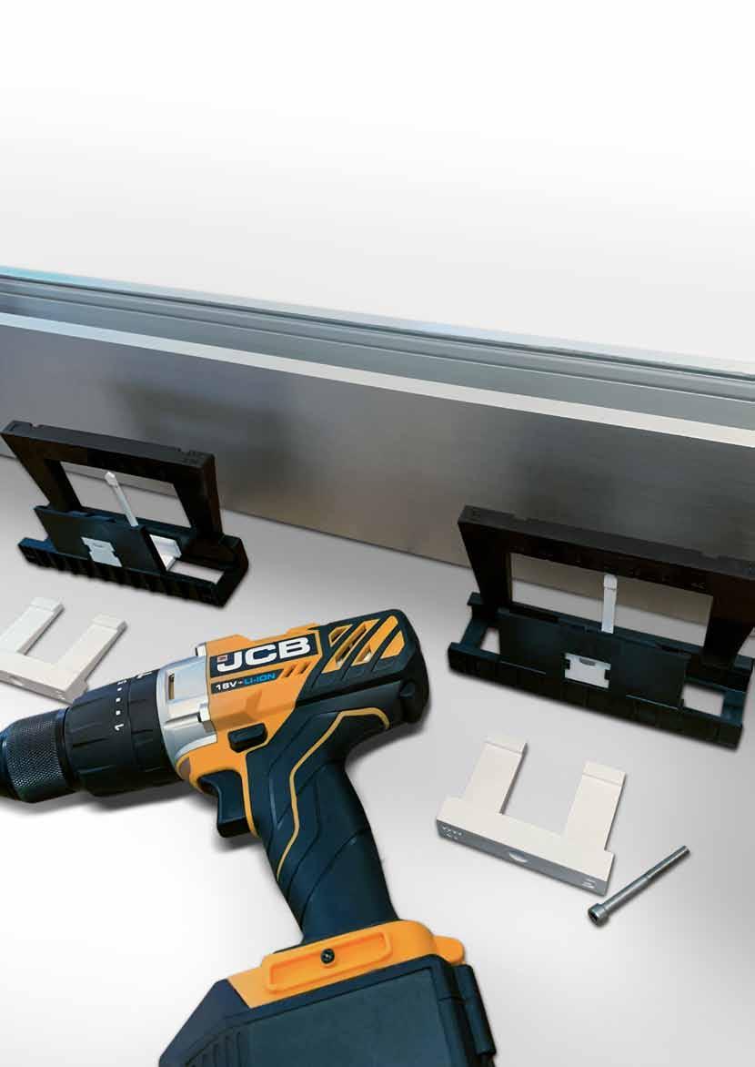
DESIGnED FOr InSTALLErS
The Fast-Track and Kwick-Lock systems have been designed with the installer in mind offering a unique system that blends mechanical and pressure fitting into one balustrade system. This unique combination will save time and money by simplifying the installation, decreasing installation time and increasing hole centres reducing the number of holes and bolts required.
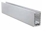
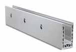
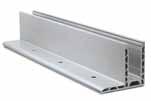
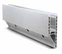
145
INSTALLATION INSTrUCTIONS Fast-Track® c hannel System Kwik-Lock® Dialed In Adjustment Kwik-Lock® MAX Installation Instructions Model 1010 Page 146 Model 1020 Page 147 Model 2010 Page 148 Model 2020 Page 149 Model 3010 Page 150 Posi-Glaze Page 154 Mega Grip Page 155 www.fastechandrails.co.uk
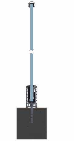
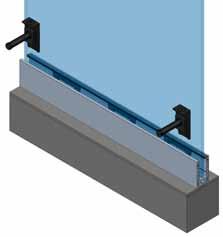
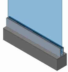
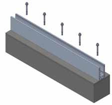
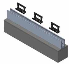
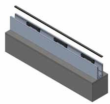
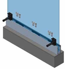
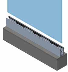
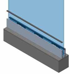
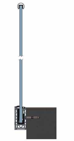
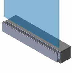
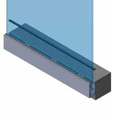
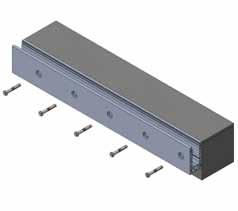
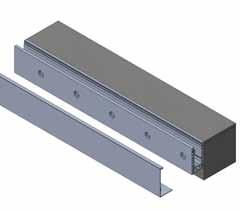
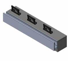
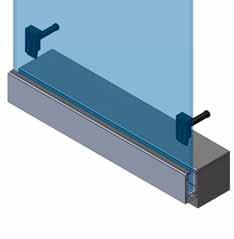
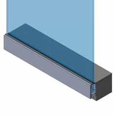
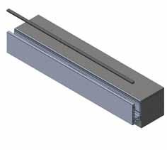
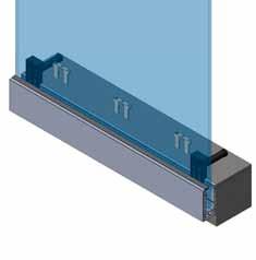
146 147 MODEL 1010 | MOUNTiNG iNSTrUcTiONS MODEL 1020 | MOUNTiNG iNSTrUcTiONS 1 1 3 3 6 6 5 5 8 8 9 2 2 4 4 7 7
600mm Ctrs 0.74kN 600mm Ctrs 1.5kN 400mm Ctrs 3kN 200mm Ctrs 0.36kN 600mm Ctrs 0.74kN 600mm Ctrs 1.5kN 200mm Ctrs 3kN 200mm Ctrs 1250 MAX 1100 MAX 200-600Fixings Fixings200-600 312 190Max HoleCtrs 200 Hole200Ctrs 312 190Max www.fastechandrails.co.uk www.fastechandrails.co.uk
0.36kN
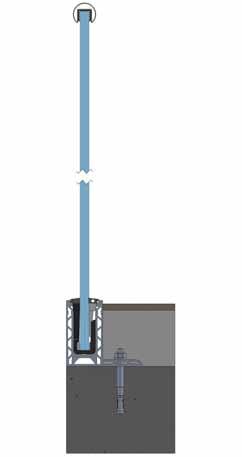
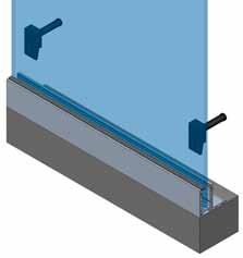

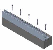
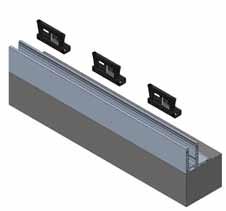
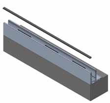
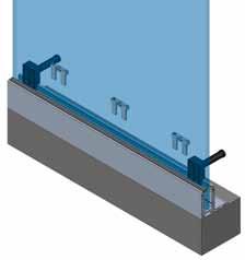
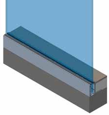
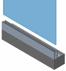
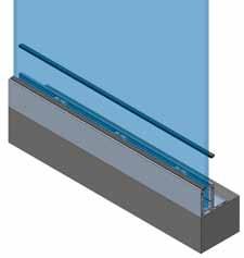
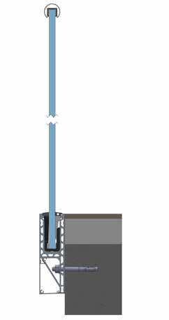
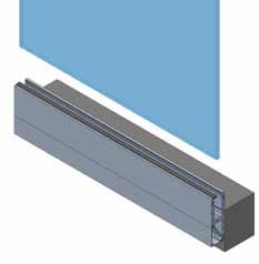
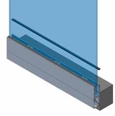
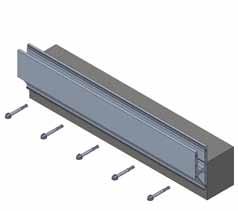
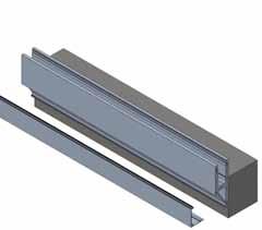
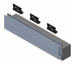
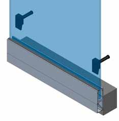
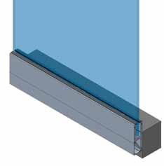
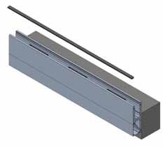
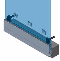
148 149 MODEL 2010 | MOUNTiNG iNSTrUcTiONS MODEL 2020 | MOUNTiNG iNSTrUcTiONS 1 3 6 5 8 9 2 4 7 0.36kN 400mm Ctrs 0.74kN 600mm Ctrs 1.5kN 200mm Ctrs 3kN 200mm Ctrs 1100 MAX Fixings200-600 Hole200Ctrs 1 3 6 5 8 9 2 4 7 0.36kN 400mm Ctrs 0.74kN 400mm Ctrs 1.5kN 200mm Ctrs 3kN 200mm Ctrs 1250 MAX 200-400Fixings 312 190Max HoleCtrs 200 312 190Max www.fastechandrails.co.uk www.fastechandrails.co.uk
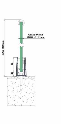
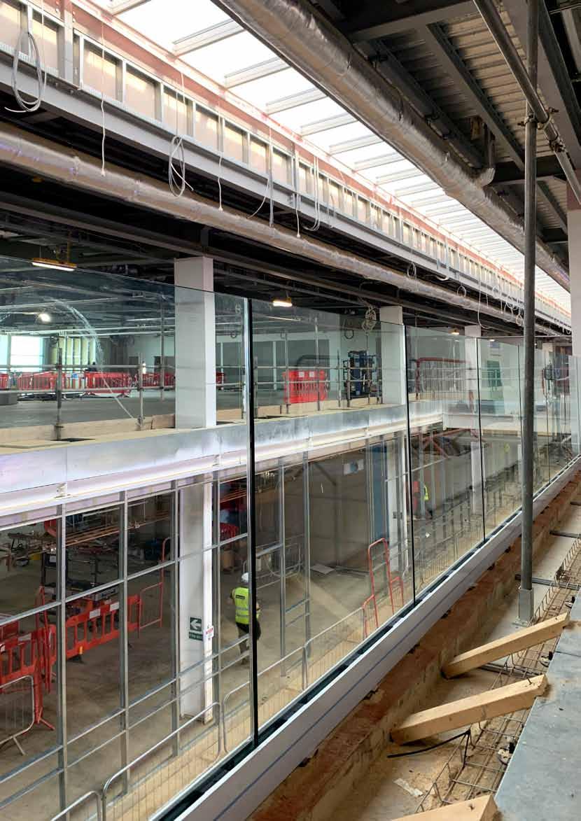
150 MODEL 3010 | MOUNTiNG iNSTrUcTiONS 1 3 6 5 8 2 4 7 200-600Fixings 312 190Max HoleCtrs 200 0.36kN 600mm Ctrs 0.74kN 600mm Ctrs www.fastechandrails.co.uk

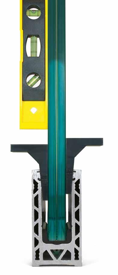
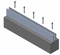
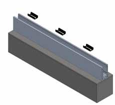
Positionglassretainers
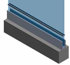
Pushinfoamstrips25mmdown
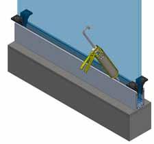
Mixandapplysealant(15mmthicklayer)
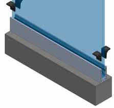
Secureglasswithwedges
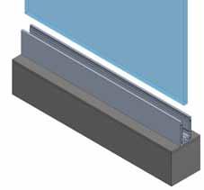

Adjustglassbyraising/loweringwedges
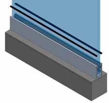
Finishwithtopsealrubbers
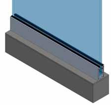
152 153 KWICK-LOCK MAX | iNSTrUcTiONS 1 3 6 5 8 9 2 4 7
Insertglass
FastenwithFixings
KWICK-LOCK MAX | iNSTrUcTiONS Fixings 200 312 190Max 25 www.fastechandrails.co.uk www.fastechandrails.co.uk
1 Base Rail
The aluminium base rail should be placed onto its designated position and the holes marked onto the substrate for drilling. The channel should then be levelled and lined up with the use of shims. Once the shoe is plumb and level, the fixings should be tightened up to make the channel rigid. The fixings must be tightened in accordance with the manufacturers instructions.
2 Glass Slip Clamp Fitting
The glass slip clamps need to be placed on the bottom of the glass. This requires lifting the glass off the floor sufficiently or turning the glass upside down to squeeze these on. The slip clamps require spacing so that four are used per metre. The clamps placed on either end of the glass should be located 125mm in from the edge of the glass and then 250mm to the next clamp. The glass can now be placed into the channel.
3 Glass Clamp Bar Fitting
Once the glass is fitted in place, you now need to place the clamp bars into the top of each glass slip clamp. First you must screw the bolt into the clamp bar until the head of the bolt just reaches the bar. The shaped side of the bar will sit nearest to the glass. You can now sit each clamp bar into the glass slip clamps.
4 Getting Glass Plumb and Tightening Bolts
You now need to place a spirit level on the glass to get the glass in the correct position. The bolts now need tightening into the channel equally to keep the same pressures on the glass. To adjust the glass into position you must unscrew the bolts back onto the channel. To achieve the correct positioning firstly square up and level each end of the glass and tighten. Then tighten the intermediate clamp bars.
Once the bolts have pinched, they now need a half turn to securely hold the glass in place. For extra protection we would suggest the use of an adhesive on the thread of the bolts.
5 Top Seal Strip
The gasket requires feeding into the smaller profile supplied, you must not stretch the gasket. Once the gasket is flush with each end of the strip it now needs to be clipped onto the top of the channel, this can be done by pressing firmly down on the profile. Working from one end to the other is recommended.
6 Cleaning
Once you are happy everything is in place and the job is complete you need to clean the glass and channel. We recommend the use of any standard glass cleaner so long as it is not abrasive. We also recommend a soft sponge or cloth, again to avoid any risk of scratching.
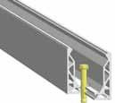
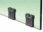
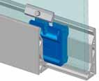
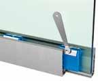
1 Base Rail
The aluminium base rail should be placed onto its designated position and the holes marked onto the substrate for drilling. Once the shoe is level, the fixings should be tightened up to make the channel rigid. The fixings must be tightened in accordance with the manufacturers instructions.
2 Glass Slip Clamp Fitting
The glass slip clamps need to be placed on the bottom of the glass. This requires lifting the glass off the floor sufficiently or applying to the top of the glass and rotating into the channel. The slip clamps require spacing so that four are used per metre. The clamps placed on either end of the glass should be located 125mm from the edge of the glass and then 250mm centres.
The glass can now be placed into the channel.
3 Preparing the Mega-Hook
The clamp bar needs to be slid over the screw threaded end and the bolt loosely tightened so the bar can easily spin into the correct position.
4 Glass Clamp Bar Fitting
You now need to place the Grapple hooks into the top of each glass slip clamp. Lower the hook next to the plastic clamp, and hook into the metal lip. The angled side of the plastic clamp bar must face the angled glass clamp.
As shown in the image to the right.
5 Getting the glass level
You now need to get the glass level. Manoeuvre the glass whilst the bolts are loose until it is in in the correct position.
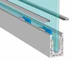
Now the bolts can be tightened, firstly finger tighten each side before using a ratchet/torque bar. The bolts must be tightened to 15Nm.
6 Top Seal Strip/Cladding
The gasket requires feeding into the Side cladding and/or top bead supplied, you must not stretch the gasket. Once the gasket is flush with each end of the strip it now needs to be clipped onto the top of the channel, this can be done by pressing firmly down on the profile. Working from one end to the other.
The Side cladding has a lower clip which must line in the channel it must then be firmly pushed at the top towards the glass. Addition securing tape can be applied.
7 Cleaning
Once you are happy everything is in place and the job is complete, you need to clean the glass and channel. Use a non abrasive glass cleaner on the glass and warm soapy water on the MegaGrip channel. We also recommend a soft sponge or cloth, again to avoid damaging the channel or glass.
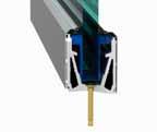
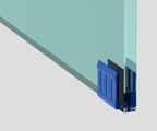
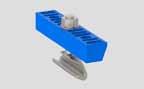
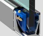
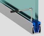
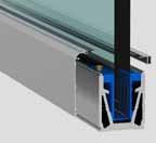
154 155
POSI-GLAZE | MOUNTiNG iNSTrUcTiONS
MEGAGrIP | MOUNTiNG iNSTrUcTiONS www.fastechandrails.co.uk www.fastechandrails.co.uk


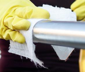
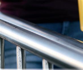


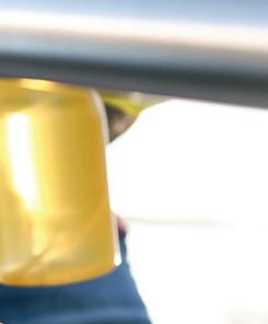
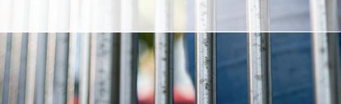

care and maintenance
To gain the maximum benefits from the Fastec range, the correct care and maintenance procedures should be followed during and after installation.
To achieve maximum corrosion resistance and appearance, the surface of the stainless steel must be kept clean; this is extremely important when used in an external environment.
It is necessary to clean your installation immediately after fitting is complete using Fastec Stain Remover. Following this, periodical cleaning with Fastec Stainless Steel Cleaner will help form a protective barrier against the atmosphere.
Installations in an external environment will require a cleaning schedule to be followed, this is a periodic cleaning off approximately every 3-6/6-12 months thereafter.
For installations in aggressive environments for example coastal regions and swimming pools, you will need to take particular care with cleaning and maintenance to inhibit corrosion. The cleaning schedules relating to these types of areas are much more frequent than standard external installations. In addition, we strongly recommend that only mirror polished items are installed in such environments due to their higher corrosion resistant finish.
cleaning methods
To assist with care and maintenance we provide Fastec Stainless Steel Cleaner and Fastec Stain Remover.
Fastec Stainless Steel Cleaner is a general purpose stainless steel cleansing spray. It can be used in conjunction with Fastec Stain Remover or as a cleaning product in its own right to clean and shine stainless steel.
Fastec Stain Remover is an acid based cleaner which temporarily strips the stainless steel of its passive layer so any contaminants can be removed. It should then be washed off with water which neutralises the acid and causes the passive layer to regenerate on the surface of the stainless steel. This surface should be periodically protected with Fastec Stainless Steel Cleaner.
Hints and tips ➲

Always clean your installation once it has been completed. This is necessary to remove any contaminants on the surface of the material to prevent future problems and leaves a finished look behind for your customer.
For outstanding results, use Fastec Stainless Steel Cleaner for internal installations and Fastec Stain Remover followed by Fastec Stainless Steel Cleaner for external applications.
Always use a lint-free cloth, never use an abrasive cleaner or cloth.


It is important to remember that masonry and brick cleaners contain acid, so protect any stainless steel surfaces during their use. Any splashes should be washed off straight away with water.
Further information on cleaning schedules and maintenance can be found on our website.
157 CARE AND MAINTENANCE
www.fastechandrails.co.uk
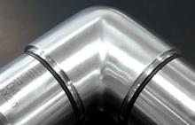
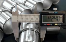
customer care
Our focus is your business.
Fastec is a customer-focused company. We take a meticulous approach to serving our customers, from initial enquiry through to delivery and after-sales services.
Providing the products and services our customers require is the key to our success. That’s why we are proactive in anticipating the evolving needs of our customers.
Our highly experienced and knowledgeable technical experts will quickly understand the nature of your project and your precise requirements.
We are happy to deal with all your questions and enquiries and our experts will be able to guide you through our extensive range of products and the ordering process – whether you’re working on a small domestic project or a substantial commercial or architectural development.
Above all, it is the level of personal service we provide, backed by our experience, knowledge and expertise, that ensures we always meet and frequently exceed our customers’ expectations.
We aim to provide the best quality products within the market place. To ensure this, all the fittings within the Fastec range are manufactured and inspected to meet your high standards.
Fastec Handrail Systems has gained BS EN ISO9001: 2008 accreditation ensuring you benefit from exceptional product quality and service levels.
This accreditation guarantees that we conform to stringent quality control procedures. Ensuring we get it right first time, every time – so you will too.
information
Delivery
Fastec dispatch all orders via carrier on a next day service.
Orders must be received before 2.00pm to be dispatched same day.
Upgraded timed delivery services are available (ie. before noon, before 10.30am, Saturday am) at an additional cost.
Off-shore and some Scottish Highlands locations are only available on a 2-3 day service.
Price /Payment
All prices quoted are net, VAT will be added.
Delivery charges are in addition to the fitting prices and will be stated at time of quoting/ordering.
Accounts not settled within the agreed time period will be placed on stop and no further goods will be dispatched until the overdue monies are settled.
Returns
Goods will only be accepted if they are received in a resaleable condition and in their original packaging.
Notification of a return must be made in writing in the first instance and must be received within 1 month after receipt.
A handling fee will be charged, the amount will be confirmed after a notification has been received. Goods ordered incorrectly or in excess must be returned by the customer at their own expense.
Claims
Notice of any claim relating to shortages or damaged goods shall be made to the company in writing within 48 hours of receipt of goods. In the event of loss or non-delivery of the goods the customer shall notify the company in writing within 3 days of receiving the advice note.
All goods received damaged on delivery must be signed for as ‘Damaged’, claims for goods received as damaged but signed for as ‘Received in good condition’ will not be accepted.
Quantities must be checked on delivery before signing as accepted.
Terms & Conditions
We reserve the right to change any products within this brochure relating to the design and measurements without prior warning. Products may be updated or revised and actual products may be slightly different to the items illustrated.
Different shapes and product types may have slightly different polishing matches due to the techniques and processes used.
We cannot be held responsible for printing errors.
The company shall not be responsible for any expenditure losses. Any compensation is limited to the value of the goods.
Our full terms & conditions are available on request.
158
quality
RS24788 159
➲
£ Fastec Handrail Systems Fastec Handrail Systems

Enquiry Sheets
Posts Made To Your Requirements

160 161
ENQUIRY SHEETS Quantity Type Sender Sender Name: Tel: Fax: Email: Company: Street: Town: Postcode: Glass clamps Glass clampGlass thickness L =980 mm □ MOD: 30 □ 8 mm □ L =1060 mm □ MOD: 31 □ 8,76 mm □ or MOD: 32 □ 10 mm □ L: mm MOD: 33 □ 10,76 mm □ MOD: 34 □ 11.52 mm □ L1: mm MOD: 35 □ 12 mm □ MOD: 38 □ 15 mm □ L2: mm Glass clamps Glass clampGlass thickness L =980 mm □ L =1060 mm □ or MOD: 30 □ 8 mm □ L: mm MOD: 31 □ 8,76 mm □ MOD: 32 □ 10 mm □ L1: mm L2: mm L3: mm L4: mm MOD: 33 □ 10,76 mm □ MOD: 34 □ 11.52 mm □ MOD: 35 □ 12 mm □ MOD: 38 □ 15 mm □ Crossbar holders Holes per post L =980 mm □ L =1060 mm □ or L: mm L1: mm 12 mm Infill bar □ L2: mm 16 mm Infill bar □ Wire-tec cable system Eye bolts per post L =980 mm □ L =1060 mm □ or L: mm L1: mm 3,2 mm Wire □ L2: mm 6,0 mm Wire □ R= ° R= ° R= ° R= ° R R R R Grade L2 L4 L1 L3 304 □ 316 □ Specials form Base Ø 42,4 x 2,0 mm □ Ø 42,4 x 2,6 mm □ Ø 48,3 x 2,0 mm □ Ø 48,3 x 2,6 mm □ MOD: 1100 ■ MOD: 1110 ■ MOD: 1120 ■ L L2 L1 L L2 L1 L L2 L1 www.fastechandrails.co.uk

162 Grade Base Quantity Type Sender Sender Name: Tel: Fax: Email: Company: Street: Town: Postcode: Glass clamps Glass clampGlass thickness MOD: 30 □ 8 mm □ MOD: 31 □ 8,76 mm □ MOD: 32 □ 10 mm □ L: mm MOD: 33 □ 10,76 mm □ MOD: 34 □ 11.52 mm □ L1: mm MOD: 35 □ 12 mm □ MOD: 38 □ 15 mm □ L2: mm Glass clamps Glass clampGlass thickness L =980 mm □ L =1060 mm □ or MOD: 30 □ 8 mm □ L: mm MOD: 31 □ 8,76 mm □ MOD: 32 □ 10 mm □ L1: mm L2: mm L3: mm L4: mm MOD: 33 □ 10,76 mm □ MOD: 34 □ 11.52 mm □ MOD: 35 □ 12 mm □ MOD: 38 □ 15 mm □ L L2 L4 L1 L3 Crossbar holders Holes per post L: mm L1: mm 12 mm Infill bar □ L2: mm 16 mm Infill bar □ Wire-tec cable system Eye bolts per post L: mm L1: mm 3,2 mm Wire □ L2: mm 6,0 mm Wire □ 304 □ 316 □ Ø 42,4 x 2,0 mm □ Ø 42,4 x 2,6 mm □ Ø 48,3 x 2,0 mm □ Ø 48,3 x 2,6 mm □ MOD: 1000 ■ MOD: 1010 ■ MOD: 1020 ■ MOD: 1030 ■ R= ° R= ° R= ° R= ° Specials form R R R R L L1 L2 L L2 L1 L2 L1 163 Grade Quantity Type Sender Sender Name: Tel: Fax: Email: Company: Street: Town: Postcode: L L2 L1 Glass clamps Glass clampGlass thickness L =980 mm □ MOD: 30 □ 8 mm □ L =1060 mm □ MOD: 31 □ 8,76 mm □ or MOD: 32 □ 10 mm □ L: mm MOD: 33 □ 10,76 mm □ MOD: 34 □ 11.52 mm □ L1: mm MOD: 35 □ 12 mm □ MOD: 38 □ 15 mm □ L2: mm Glass clamps Glass clampGlass thickness L =980 mm □ L =1060 mm □ or MOD: 30 □ 8 mm □ L: mm MOD: 31 □ 8,76 mm □ MOD: 32 □ 10 mm □ L1: mm L2: mm L3: mm L4: mm MOD: 33 □ 10,76 mm □ MOD: 34 □ 11.52 mm □ MOD: 35 □ 12 mm □ MOD: 38 □ 15 mm □ L2 L4 L1 L3 Crossbar holders Holes per post L =980 mm □ L =1060 mm □ or L: mm L1: mm 12 mm Infill bar □ L2: mm 16 mm Infill bar □ L L2 L1 Wire-tec cable system Eye bolts per post L =980 mm □ L =1060 mm □ or L: mm L1: mm 3,2 mm Wire □ L2: mm 6,0 mm Wire □ L L2 L1 304 □ 316 □ Ø 42,4 x 2,6 mm □ Ø 48,3 x 2,6 mm □ R= ° R= ° R= ° R= ° Specials form R R R R
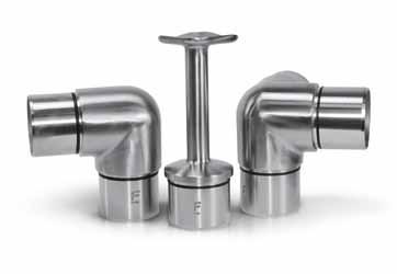
MOd
MOd
MOd
MOd
MOd
MOd
U-Section Handrail
Profiled Handrail - rectangle
MOd
MOd 7020 Profiled Handrail Elbow Page 48 MOd 7050 Profiled Handrail connector Page 48
MOd 7060 Profiled Handrail Wall Flange Page 48 MOd 7070 Profiled Handrail End cap Page 48 MOd 7042 Profiled Handrail rubber Page 48 MOd 7142 Profiled Handrail rubber Page 48
Profiled Handrail - round Mirror
MOd 7000 Profiled Handrail Page 49
MOd 7010 Profiled Handrail Elbow Page 50 MOd 7020 Profiled Handrail Elbow Page 50 MOd 7030 Profiled Handrail Elbow Page 50 MOd 7040 Profiled Handrail Elbow Page 50
MOd 7050 Profiled Handrail connector Page 50
MOd 7060 Profiled Handrail Wall Flange Page 50
MOd 7070 Profiled Handrail End cap Page 49
MOd 7042 Profiled Handrail rubber Page 49
MOd 7142 Profiled Handrail rubber Page 49
MOd 7048 Profiled Handrail rubber Page 49
MOd 7148 Profiled Handrail rubber Page 49
Glass Spigots
MOd 5010 Top Mount Spigot Page 53
MOd 5020 Side Mount Spigot Page 53
Alu-rail
MOd 8010 End Post Page 57, 58
MOd 8020 Mid Post Page 57, 58
MOd 8030 corner Post Page 57, 58
Fittings
MOd 0100 Stem connection Page 65
MOd 0105 Stem connection Adj Page 65
MOd 0110 Stem connection Page 65
MOd 0111 Stem connection Page 65
MOd
index Fast-Track
1010 Top Fix Base Profile Page 17
1020 Side Fix Base Profile Page 19
2010 Top Fix Base Profile Page 23
2020 Side Fix Base Profile Page 27
Top Fix Base Profile Page 31
3010
Extension Pin Page 17,20,23,27,31,33
9201
Mounting Anchor Page 17,24,28,31,33
9612 Mounting Anchor Page 20, 33
MOd 9512
MOd
Kwik-Lock Wedge Kit Page 17,20,24,28,31
MOd 0125/0150
Kwik-Lock MAx Wedge Kit Page 17, 20, 24, 28
MOd 0250
Tool Kit Page 32
MOd 9500
Adjustment Tool Page 32
MOd 9504
Blocks Page 32
MOd 9505 Placement
Tool Page 32
MOd 9506 Wedge removal
Flex Extension Page 32
Silver Silicone Page 32
MOd 9507
MOd 9510
MOd 7200 U- Handrail
45 MOd 7220 U- Handrail connector Page 45 MOd 7225 U- Handrail Connector 90˚ Page 45 MOd 7270 U- Handrail End cap Page 45 MOd 7027 U- Handrail rubber Page 45
Page
7000 Profiled Handrail Page 48
0115 Stem connection Adj Page 65 MOd 0116 Stem connection Adj Page 65 MOd 0120 Stem Connection 135˚ Page 66 MOd 0121 Stem Connection 135˚ Page 66 MOd 0130 Stem Connection 90˚ Page 66 MOd 0131 Stem Connection 90˚ Page 66 MOd 0135 Stem connection c/w Adj elbow Page 67 MOd 0140 Stem connection Weldable Page 67 MOd 0150 Blade Stem connection Page 68 MOd 0155 Blade Stem Connection 90˚ Page 68 Profiled Handrail - round MOd 7000 Profiled Handrail Page 46 MOd 7010 Profiled Handrail Elbow Page 47 MOd 7020 Profiled Handrail Elbow Page 47 MOd 7030 Profiled Handrail Elbow Page 47 MOd 7040 Profiled Handrail Elbow Page 47 MOd 7050 Profiled Handrail connector Page 47 MOd 7060 Profiled Handrail Wall Flange Page 47 MOd 7070 Profiled Handrail End cap Page 46 MOd 7042 Profiled Handrail rubber Page 46 MOd 7142 Profiled Handrail rubber Page 46 MOd 7048 Profiled Handrail rubber Page 46 MOd 7148 Profiled Handrail rubber Page 46 MOd 7060 Profiled Handrail rubber Page 46 MOd 7160 Profiled Handrail rubber Page 46 Posi-Glaze MOd PGc – 010 Top Fix Base Profile Page 37 MOd PGA – 010 Top Fix Side cladding Page 37 MOd PGA – 030 Top Seal Strip Page 37, 41 MOd PGA – 050 Spanner Page 37, 38, 42 MOd PGA – 060 Top Fix End cap Page 37 MOd PGA – 070 Extension Pin Page 37, 38, 42 MOd PGA – 090 Top Fix corner Page 37 MOd PGB clamp Kits Page 37, 38, 42 MOd 9612 Mounting Anchor Page 37, 38, 42 MOd PGc – 010BK Top Fix Base Profile - Black Page 38 MOd PGA – 030BK Top Seal Strip - Black Page 38 MOd PGA – 060BK Top Fix End cap - Black Page 38 MOd PGA – 090BK Top Fix corner - Black Page 38 MOd PVA – Touch Black Touch Up Pen Page 38 MOd PGc – 020 Side Fix Base Profile Page 41 MOd PGA – 020 Side Fix Side cladding Page 41 MOd PGA – 061 Side Fix End cap Page 41 MOd PGA – 062 Side Fix End cap Page 41 MOd PGA – 065r Side Fix End cap Page 41 MOd PGA – 065L Side Fix End cap Page 41 164 MOd: 0157 Blade Stem connection Weldable Page 68 MOd: 0200 Stem connection Page 70 MOd: 0205 Stem connection Adj Page 70 MOd: 0210 Stem Connection 135˚ Page 70 MOd: 0220 Stem Connection 90˚ Page 70, 71 MOd: 0300 Handrail Saddle Page 71 MOd: 0303 Handrail Saddle 90˚ Page 71 MOd: 0310 Stem connection Page 71 MOd: 0315 Stem connection Page 71 MOd: 0400 Handrail Brackets, Flat Page 72 MOd: 0405 Handrail Brackets, Flat Adj Page 72 MOd: 0415 Handrail Brackets, Tube Adj Page 73 MOd: 0420 Handrail Brackets, Tube Page 73 MOd: 0425 Handrail Brackets, Tube Adj Page 73 MOd: 0430 Handrail Brackets, Wall Page 74 MOd: 0435 Handrail Brackets, Wall Adj Page 74 MOd: 0440 Handrail Brackets, Glass Page 75 MOd: 0445 Handrail Brackets, Glass Adj Page 75 MOd: 0510 Handrail Brackets, Wall Page 76 MOd: 0511 Handrail Brackets, Wall Page 76 MOd: 0520 Handrail Brackets, Wall Page 76 MOd: 0521 Handrail Brackets, Wall Page 76 MOd: 0525 Handrail Brackets, Wall Adj Page 77 MOd: 0530 Handrail Support Page 77 MOd: 0540 Wall rosette Page 77 MOd: 0541 Stem connection Page 77 MOd: 0542 rosette cover Page 77 MOd: 0600 Elbow Page 78 MOd: 0610 Elbow Page 78 MOd: 0620 Elbow Page 78 MOd: 0630 Elbow Page 78 MOd: 0640 Elbow Adjustable Page 79 MOd: 0645 Elbow Adjustable Page 79 MOd: 0650 Elbow Weldable Page 79 MOd: 0660 return End Page 81 MOd: 0700 3 Way Tee connector Page 81 MOd: 0710 Tee connector Page 81 MOd: 0720 connector Page 81 MOd: 0730 Adaptor Page 82 MOd: 0731 Adaptor Page 82 MOd: 0735 Adaptor Adjustable Page 82 MOd: 0740 Wall Flange Page 82 MOd: 0745 Wall Flange Adjustable Page 83 MOd: 0748 Wall Flange Slim Page 83 MOd: 0750 End Ball Page 83 MOd: 0760 Support Page 83 MOd: 0800 End cap Flat - Hit n Page 84 MOd: 0801 End cap Flat - Hit n Page 84 MOd: 0810 End cap raised - Hit n Page 84 MOd: 0811 End cap raised - Hit n Page 84
0820 End cap domed - Hit n Page 85 MOd: 0850 End cap Flat Page 85 MOd: 0860 End cap raised Page 85 MOd: 1000 Side Fix Bracket Page 86 MOd: 1010 Side Fix Bracket Page 86 MOd: 1020 Side Fix Bracket Page 86 165
MOd:
Fastec Handrail Systems Fastec Handrail Systems
MOd 8050 rubber Seal Page 57, 58
MOd:
MOd: 7000 Juliet Handrail Page 115
MOd: 4000 Fixing Brackets Page 115
MOd: 7042 Handrail rubber Page 115
MOd: 7142 Handrail rubber Page 115
MOd: 7048 Handrail rubber Page 115
MOd: 7148 Handrail rubber Page 115
Glass connectors & Panel holders
MOd: 4010 Glass connectors Page 117
MOd: 4020 Glass connectors Page 117
MOd: 4030 Glass connectors Page 118
MOd: 4100 Glass connectors Page 118
MOd: 4500 Panel holders Page 119
MOd: 4510 Panel holders Page 119
MOd: 9180 Threaded nsert Page 118
MOd: 6000 Tensioner Page 121
MOd: 6010 Terminal Page 121
MOd: 6020 Eye Bolt Page 121
MOd: 6030 cable Stopper Page 121
MOd: 6100 Tensioner Page 122
MOd: 6110 crossbar Holder Page 122
MOd: 6120 crossbar Holder Page 122
MOd: 6130 crossbar Holder Page 122
MOd: 6203 Wire 3.2mm Page 121, 122
MOd: 6206 Wire 6.0mm Page 121, 122
MOd: 6350 cable cutter Page 121
Timber-tec
Accessories
MOd: 9010 Glue Page
MOd: 9020 Stainless
8040 End cap Page 126
8050 connector Page 126
8060 Spigot Page 126
Tubes & Bars MOd 1900 Bars & Tubes PAGE 129
1910 Bars & Tubes PAGE 129
9140 coach Screws Page
MOd: 9150 Screw Page 133 MOd: 9180 Threaded nsert Page 133 MOd: 9200 c Spanner Page 131
MOd: 9300 Allen Key Set Page 131 MOd: 9400 Tube cutter Page
166 167 Fittings cont. MOd: 1030 Side Fix Bracket Page 86 MOd: 1040 Side Fix Bracket Page 86 MOd: 1050 Side Fix Bracket n-Line Page 87 MOd: 1060 Side Fix Bracket n-Line Page 87 MOd: 1100 Welded Base Page 88 MOd: 1101 Base cover Page 88 MOd: 1110 Welded Base Page 88 MOd: 1111 Base cover Page 88 MOd: 1120 Welded Base Page 88 MOd: 1121 Base cover Page 88 MOd: 1105 Glue-in Base Page 89 MOd: 1150 Glue-in Base Adjustable Page 89 MOd: 1200 Welded Base Page 89 MOd: 1210 Welded Base Page 89 MOd: 1250 Welded Base Page 89 MOd: 1280 Spigot cover Page 89 MOd: 1300 Welded nsert Page 90 MOd: 1310 nner Flange Page 90 MOd: 1311 nner Flange rubber Page 90 MOd: 1320 Outer Flange Page 90 MOd: 1321 Outer Flange rubber Page 90 MOd: 1510 Baluster Post Page 91 MOd: 1520 Baluster Post Page 91 MOd: 1530 Baluster Post Page 91 MOd: 1610 Baluster Post Page 91 MOd: 1620 Baluster Post Page 91 MOd: 1630 Baluster Post Page 91 MOd: 1710 Baluster Post Page 90 MOd: 1630 Pre-Assembled Baluster Post Page 92 MOd: 2010 crossbar Holder Page 94 MOd: 2012 crossbar Holder Page 94 MOd: 2212 crossbar Holder Page 94, 95 MOd: 2312 crossbar Holder Page 94, 95 MOd: 2416 crossbar Holder Page 95 MOd: 2812 nline crossbar Holder Page 95 MOd: 2912 nline crossbar Holder - Adj Page 95 Mirror Polished MOd: 0110 Stem connection Page 97 MOd: 0115 Stem connection Adj Page 97 MOd: 0130 Stem Connection 90˚ Page 97 MOd: 0440 Handrail Brackets, Glass Page 97 MOd: 0445 Handrail Brackets, Glass Adj Page 97 MOd: 0521 Handrail Brackets, Wall Page 97 MOd: 0610 Elbow Page 98 MOd: 0640 Elbow Adjustable Page 98 MOd: 0720 connectors Page 98 MOd: 0731 connector Page 98 MOd: 0740 Wall Flange Page 98 MOd: 0860 End cap raised Page 98 MOd: 1010 Side Fix Bracket Page 99 MOd: 1101 Base cover Page 99 MOd: 1510 Baluster Post Page 99 MOd: 1900 Bars & Tubes Page 99 MOd: 1910 Bars & Tubes Page 99 MOd: 32 Glass clamp - Model 32 Page 99 Glass Clamps MOd: 30 Glass clamps - Model 30 Page 101 MOd: 31 Glass clamps - Model 31 Page 102 MOd: 32 Glass clamps - Model 32 Page 103, 104, 105 MOd: 32.100 n-Line Glass clamps - Model 32 Page 106 MOD: 32.200 90˚ Glass clamps - Model 32 Page 106 MOd: 33.100 in-Line Glass clamps - Model 33 Page 106 MOD: 33.200 90˚ Glass clamps - Model 33 Page 106 MOd: 33 Glass clamps - Model 33 Page 107 MOd: 34 Glass clamps - Model
34 Page 108
Glass
35
clamps - Model 35 Page 109
Glass
Glass
Glass clamp
Glass
Glass
Glass
MOd: 38
clamps - Model 38 Page 111 MOd: 39
clamps - Model 38 Page 111
rubbers
clamp rubbers Page 112,113
clamp pins
clamp Security Pins Page 113 Wire-tec
Juliet Balcony
MOd
MOd
MOd
MOd
MOd
MOd
MOd 6400 Alignment Tool Page 126 MOd 8000 Handrail Page 125
8010 Elbow Page 125
8020 Elbow Adjustable Page 125
8030 return End Page 126
MOd
131
cleaner
131
131
remover Page 131
Kit Page 131
Bolt Page 132 MOd:
Page 132 MOd:
Page 132 MOd:
Page 132 MOd:
Page
MOd: 9025 Glass Gleaner Page
MOd: 9030 Stain
MOd: 9040 cleaner
MOd: 9100
9101 Bolt
9110 Bolt
9120 Bolt
9130 dual Head Screw Page 133 MOd:
133
131 Fastec Handrail Systems Fastec Handrail Systems
Innovative Handrail Solutions
Handrail Systems
Fastec


Handrail Systems Limited
Barrett House, Cutler Heights Lane
Bradford, West Yorkshire, BD4 9HU
Tel: 01274 474330
Fax: 01274 474361
Email: sales@fastechandrails.co.uk
Fastec
