
Design of Machines and Structures, Vol. 9, No. 1 (2019), pp. 13–23
DOI: 10.32972.dms.2019.002
INVESTIGATION AND OPTIMIZATION OF THE ACOUSTIC PERFORMANCE OF FORMULA STUDENT RACE CAR INTAKE SYSTEM USING COUPLED MODELLING TECHNIQUES
BARHM MOHAMAD1 –KAROLY JALICS 2 –ANDREI ZELENTSOV3
Abstract: The University of Miskolc has previously designed and prototyped several race cars for the FormulaStudent(FS)competition. Unfortunately, noneofthesecarsutilized airintakesystems meeting all the requirements of regulations. Intake system are used to feed the engine with sufficient amount of air for complete combustion inside the combustion chamber to produce maximum power. The air flow during flowing produce sound waves due to rate of turbulence and boundary layer separation, and accordingto standard regulation this sound shouldbecontrolled minimumaspossible. Recent advances in modelling procedures for accurate performance prediction have led to the development of modelling methods for practical intake system components in commercial design. Engine designers need simple and fast modelling tools, especially in the preliminary design evaluation stages. In this study, commercial software Solidworks and advanced design software Creo 4.0 were used in addition for that Computational Fluid Dynamics (CFD) analysis is performed. Frequency domain analysis is made to receive behaviour of the entire system under assumed conditions.
Keywords: Intake system, sound pressure level, flow modelling, pressure drop, computational fluid dynamics, optimization
1. INTRODUCTION
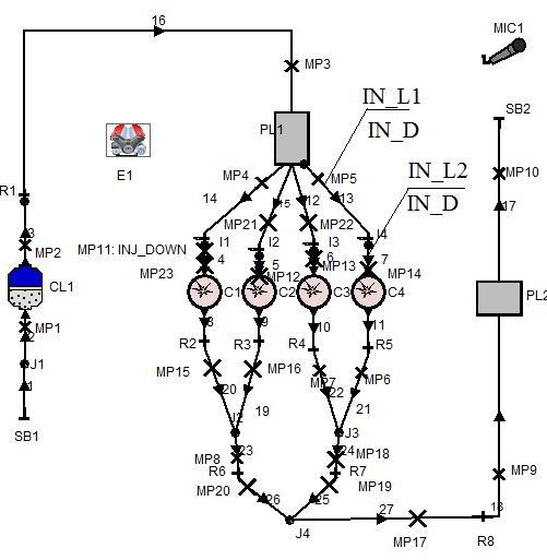
The air intake system is a major component required by internal combustion engines (ICE), and is critical regarding of the produced power of the ICE. However, in the investigated Formula Student (FS) car engine the current air intake system that was originally designed for it cannot used further due to significant power loss in certain engine speed ranges. The air intake system had seen many iterations of improvements, allowing the engine to produce increasing amount of power. This study takes a look at on the design process of the air intake system of the Formula Student [FS] car. Over the years, much of the design of this system had been carried out through an iterative trial and-error process, so the study attempts to identify the scientific and engineering principles pertaining to the design of this system. The intake system is being sub-divided into various components like restrictor, plenum and runner, then the relevant principles will be discussed. Following that, data is collected from the engine cylinders, cam-profile, intake valves etc. and a 1D simulation model of the engine will be developed using AVL Boost software. This model is then being applied (Figure 2), sequentially, to the various components. Flow analysis for individual components are carried out and verified against performance simulations of the entire engine system, followed by physical testing data of several of the components from an authorised manufacturer dealer and University of Miskolc’s engine test bed.
1, 2 University of Miskolc, Department of Machine and Product Design 3515 Miskolc-Egyetemváros, pywand@gmail.com 3 Bauman Moscow State Technical University, Piston Engine Department, 105005 Moscow, Russia Barhm Mohamad–Károly Jalics–Andrei ZelentsovComputational Fluid Dynamics tools were used in this research work, such as AVL Fire software, aid the design process through virtual simulations, including data acquisition and analysis of design variations for better information on the effects without cycling through the manufacturing and assembly processes.
Other tools, including test rigs, such as a dynamometer, are used for physical testing of manufactured componentsoftheairintakesystemwitharunningengine,andaidthedesigner in the validation of his design, which, when compared against calculations and simulations results, provides the confidence that the system is able to perform its designated task, to the required levels of performance. The engines used in the FS car competition are primarily piston-type reciprocating engines, and while the competition is dominated by race cars sporting inline-4-cylinder engines, the team has been using a Honda CBR 600RR (PC 37) engine for the last two years, particularly for its advantage in power-to-weight ratio.
2. MATHEMATICAL ANALYSIS
2.1. General
The intake system is made up of a few components placed in series and lie between the atmospheric air (intake orifice) and the intake valves of the engine. The primary function of the air intake system is to deliver air to the engine. It would be important to calculate the amount of air charge that can be sucked into the cylinder, as a ratio of the theoretical mass of air that canbe contained in the cylinder. Essentially, for a naturallyaspirated gasoline engine, it is the ratio ofthe trapped volume ofgas to the volume ofthe cylinder (Claywell et al 2006)
����: Volumetric Efficiency;
mg = ��������: mass of air that is trapped in cylinder;
mth = Theoretical mas of air that can be traaped in cylinder;
���� = ����ℎ is Volume of Cylinder, which equals theoretical Volume;
����ℎ ��������: Theoretical density of air in cylinder;
����: Volume of gas trapped in cylinder.
The method of charging the engine is by the depression (partial vacuum) created by the expanding of the combustion chamber due to the downwards moving piston. Theoretically it is possible to achieve a maximum volumetric efficiency of 100%. This value could be reduced by intake components start from restricted flow through the throttle body and intake valves, the energy loss through friction with the inner walls of the air intake system, as well as the propagation of reduced air pressure when the cylinder’s vacuum initiates. The mass flow rate under a choked flow condition can be defined by the Equation (2):
��: Mass flowrate kg/s;
CD: Discharge coefficient;
AC: Discharge hole cross-sectional area, m2;
k = ���� ���� = of the gas;
Cp: Specific heat of the gas at constant pressure;
Investigation and optimization of the acoustic performance of formula student race car intake… 15
Cv: Specific heat of the gas at constant volume;
��: Real gas density at P and T in kg/m3;
p: Absolute upstream pressure of gas, Pa.
The discharge coefficient is the ratio of the actual flow rate to the ideal flow rate of the gas, therefore in this calculation, a discharge coefficient of 1 is taken. See Table 1 below: Table
Gas and restrictor characteristics
In addition to the restrictions on the engine, that the engine must operate with gasoline, it must have an air intake restrictor through whichall ofthe air enteringthe engine have to pass. Onthe intake manifold system, the restrictor has to be placed betweenthe throttle mechanism and the engine itself. It also must not be movable or flexible in any way (Barhm 2017). This restrictor has to be circular in shape and limited to 20 mm in diameter. The dominant design of the FS race car has the engine located in the rear of the vehicle, driving non-steerable rear wheels (Baym 2006). From the specifications shown in Table 2 below, the apparent reasons forusingtheHonda CBR600RR(PC37)becomesclear, withahigherpower-to-weightratio, the Honda CBR 600RR (PC 37) engine would be a preferred choice of engine. Table
2.2. Intake runners
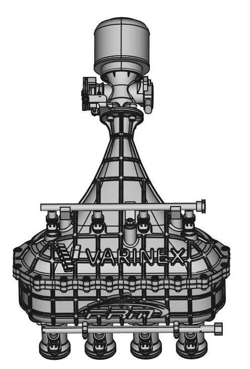
The intake runners are the parts of the air intake system which delivers air from the intake manifold to the cylinders (see Figure 1). In each runner, the dominant phenomenon that governs its performance is actually the effect of acoustic waves. As the purpose of the runner is air delivery, its performance is pegged to how much air it can deliver, and the subsequent improvement of the volumetric efficiency (Guy 2006)
2.3. Air ramming using tuned intake runners
The behaviour of acoustic waves in the runners resembles sound waves travelling through an open tube. An acoustic wave is a longitudinal wave made up of alternating regions of compressions and decompressions. In an intake runner, similar compressions and decompressions are occurring. The objective of a tuned intake runner would be to manipulate this reflected wave (while the engine is running at a desired engine speed) to make sure that a high-pressure region coincides with a subsequent valve opening. This is improving air-flow into the cylinder, improving the volumetric efficiency, hence achieving peak torque at the required engine speed (Vitek 2002). The source amplitude and impedance can be plugged upstream to the entire line to calculate the sound pressure level transmitted from the orifice as shown in Figure 1. The source reflection factor is related to the source impedance (Z) by Equation 3: �� =���� 1+�� 1 �� (3)
Where (r) is reflection factor
For a real source from the engine, the reflection factor could be frequency dependent, since the source tends to be a velocitysource at lowfrequencies and pressure source at higher frequencies.
Investigation and optimization of the acoustic performance of formula student race car intake… 17
2.4. Selecting a length for the intake runners
The calculation for the length of the tuned intake runners is based upon the duration between two events of the intake valve’s operation: the first being the closing of the intake valve, and the second being the re-opening of the intake valve on the next cycle. The trade-off for using a shorter length runner is that as the acoustic waves propagate back and forth, they will constantlylose energy, so as the runner is designed to accommodate a higher order harmonic, and therefore designed to be shorter and easier to package on the FS car, it is also suffering theeffectsofadecreasedabilitytoimprove volumetricefficiencythroughtherammingeffect of the acoustic waves.
3.
COMPUTATIONAL TOOLS
AVL Powertrain software is a powerful and simplified that allows a user to quickly carry out a Computational Fluid Dynamics (CFD) analysis on a certain assembly. It comes with a userfriendly wizard that allows the user to set up the fluid flow and fluid forces analysis.
In this segment, the AVL Advanced Simulation software is used to analyze the airflow in the air intake system. It allows the user to check on the feasibility of the designed component and carry out an initial evaluation on the feasibility and quality of a certain design.
3.1. 1D configuration
In this section, the design of the Honda CBR 600RR (PC 37) engine is being scrutinized, including the collection of data for various components of the cylinders, and creating a working model for the engine, to simulate the four cycles of the engine for further computer simulations and analysis of the intake system.
Figure 2 Engine scheme: modified parameters – volume of PL1, Intake ports length and diameter (IN_L1, IN_L2, IN_D)3.2. 3D configuration
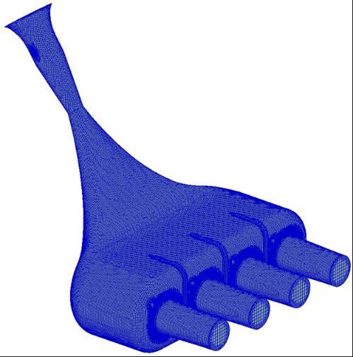
The optimization of the shape of the plenum is achieved in connection with CFD simulation (solver 3D Fire Advanced Flow) the intake manifold meshing process has been made for it with 3,115,552 elements with the geometrical optimization of the generic model of the plenum more detail of geometry shown in Table 3
Table 3
Model properties
Type of model 3D
Type of mesh
Total number of elements
The basic method used is to refine the background mesh in the region of the surfaces defined in the STL file, then remove cells that are external to the flow path, and finally snap the vertices of the cells to the STL surfaces. Control of the mesh resolution is available at various points in the meshing see Figure 3 All obtained geometric parameters of the intake manifold and other part of engine fromthe 3D scan of the engine were entered into the 1D model (such as variable diameters of the intake and exhaust pipes dependent on their length, angles in the pipe joints of the intake and exhaust manifold, materials with thermal properties, etc.). Boundary condition were set according to the engine operation, and for the air flow through restrictor to the runner k-ζ-f model was set as turbulence model to treat the turbulence regime inthe present studyinthe simulation, and nearlyrandomfluctuations in velocityand pressure in both space and time.
Investigation and optimization of the acoustic performance of formula student race car intake… 19
4. RESULTS
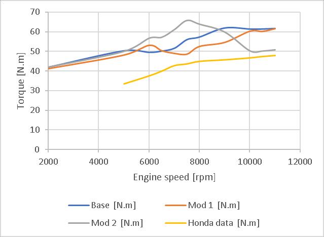
From the results shown, the improved model is documented and illustrated as Mod 1 and Mod 2 then compared with base and Honda Manufacture Company data. One of the clearest features is that the intake runner diameter was increased in Mod 1 and the plenum volume was decreased 50%, significant effect was occurred on torque line (see Figure 4). In Mod 2 the length of runner was increased from 100 to 250 mm, the diameter was reduced from 33.5 to 32 mm, and the PL1 (Plenum) volume was reduced from 4 to 3 litres.
The method here outlined may be adopted for both fluid dynamic and acoustic predictions, and then to evaluate the engine performance. The analytical of sound pressure level (SPL) solution of a simple plenum and was performed and optimized based on intake system geometry modification. Details in Figure 5
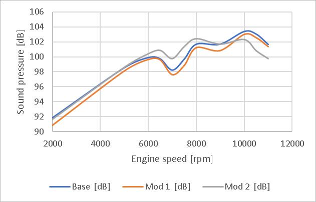 Figure 4 Comparison Torque from Honda data Co. with the base case, and two modifications 1, 2 from the software
Figure 5 Comparison SPL between base case set and the modification 1 and 2
Figure 4 Comparison Torque from Honda data Co. with the base case, and two modifications 1, 2 from the software
Figure 5 Comparison SPL between base case set and the modification 1 and 2
These design candidates were numerically implemented, and the results compared with results from base case set. In order to see the improvement through the design modification of intake system in case of rate of fuel consumption, Mod 1 and Mod 2 were also compared. It turned out, that the improvement Mod 1 has the minimum rate of fuel consumption as shown in Figure 6

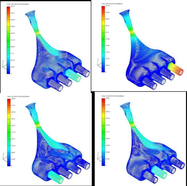
3D CFD analysis was performed at various stages in the design. Simulation was used to evaluate two important flow properties which is velocity and pressure. The velocity logically high in plenum zone and runner part which may lead to fluctuation in amount of air into the combustion chamber at high engine speed (Figure 7)
Investigation
 and optimization of the acoustic performance of formula student race car intake… 21
Figure 8 Pressure contour Min = 72217, Max = 1.00036e + 05 Pa at 8,000 rpm
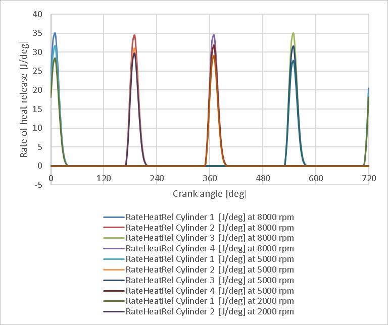
The variations of diameter and length of runner from the current designs did not show strong effects on the overall heat release in compromised intake system.
Figure 9 Rate of heat release in engine cylinders at 2,000, 5,000 and 8,000 rpm
Barhm Mohamad–Károly Jalics–Andrei Zelentsov
and optimization of the acoustic performance of formula student race car intake… 21
Figure 8 Pressure contour Min = 72217, Max = 1.00036e + 05 Pa at 8,000 rpm
The variations of diameter and length of runner from the current designs did not show strong effects on the overall heat release in compromised intake system.
Figure 9 Rate of heat release in engine cylinders at 2,000, 5,000 and 8,000 rpm
Barhm Mohamad–Károly Jalics–Andrei Zelentsov
5. CONCLUSION
The simulation was also carried out to explore the effect of the intake system geometry using a CFD perspective. The simulations were then carried out with flow being done in the three conditions:Incomparisonwiththebasecase,inthe modifications1and2the nextparameters are modified:
• Mod 1 – the diameter of the inlet channel IN_D was increased from 33.5 to 42 mm (see engine scheme in Figure 2), as well as the volume of the intake manifold PL1 was decreased from 4 to 2 litres.
• Mod 2 – the length of inlet port IN_L1 was increased from 100 to 250 mm, IN_D diameter was reduced from33.5 to32mm, PL1 volume was reduced from4 to 3 litres.
The changes were carried out step-by-step search of options with different diameters, volumes and lengths, the optimality criterion was the effective performance of the engine at different operating modes (2,000–11,000 rpm). However, this optimization procedure was performed in manual mode (search of optimal sizes with the use of Case Sets), it was not done completely automatically using AVL Boost optimizer. The advantage of using coupled 1D/3D CFD simulations is to set reliable boundary condition for simulation and presenting accurate results.
The torque is given in results. Heat release rates are available only for cylinder units (in points MP 23, 12, 13, 14 there are data for the inlet, in points MP 15, 16, 7, 6 for exhaust) Overall, it had been a rewarding experience learning about the system and carrying out tests to delve deeper into the engineering and science behind it.
ACKNOWLEDGEMENTS
The described article was carried out as part of the EFOP-3.6.1-16-2016-00011 Younger and Renewing University – Innovative Knowledge City – institutional development of the University of Miskolc aiming at intelligent specialisation project implemented in the framework of the Szechenyi 2020 program. The realization of this project is supported bythe European Union, co-financed by the European Social Fund.
REFERENCES
[1] Claywell, M.–Horkheimer, D.: Improvement of Intake Restrictor Performance for a Formula SAE Race Car through 1D & Coupled 1D/3D Analysis Methods. SAE 2006 Motorsports Engineering Conference & Exposition, December 2006, SAE 2006-013654.
[2] Barhm Mohamad–Gábor Szepesi–Betti Bollo: Combustion optimization in spark ignition engines. MultiScience – XXXI. microCAD International Multidisciplinary Scientific Conference, 2017, ISBN 978-963-358-132-2.
[3] Baym, B. et al.: An Experimental Approach to Design, Build, and Test a Throttle Bodyand Restrictor System for Formula SAE Racing. SAE 2006 World Congress and Exhibition, April 2006, SAE 2006-01-0748.
[4] Guy, R. et al.: Use of Computational Fluid Dynamics (CFD) Tools for HighPerformance Engine Tuning. SAE 2006 Motorsports Engineering Conference & Exposition, December 2006, SAE 2006-01-3666.
Investigation and optimization of the acoustic performance of formula student race car intake… 23
[5] Vitek, O.–Polasek, M.: Tuned Manifold Systems – Application of 1-D Pipe Model. Modeling of SI Engines and Multi-Dimensional Engine Modeling, SAE 2002-010004.
[6] Barhm Mohamad–Gábor L. Szepesi–Betti Bollo: Review Article: Effect of EthanolGasoline Fuel Blends on the Exhaust Emissions and Characteristics of SI Engines Lecture Notes in Mechanical Engineering, 2018, ISBN 978-3-319-75677-6.