
SUBTERRA
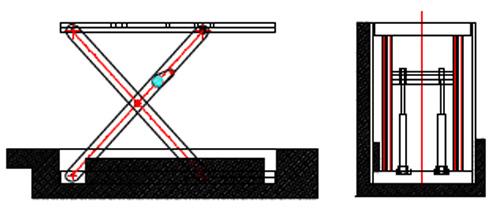
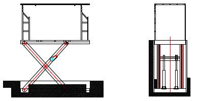
Ensure the bottom of the pit is level, correcting any horizontal errors if necessary. Mark the installation pit based on the actual equipment size. When placing the lifter into the pit, use appropriate steel shims to level it, then fill in the gaps. Additionally, ensure the walls are perfectly vertical.
The error in the pit’s diagonal should be less than 10mm. Ensure that the upper opening of the pit is vertically aligned with the opening on the second floor.
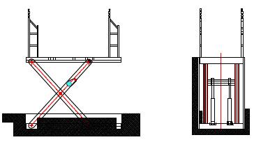
2 Lowering the lift into the pit.
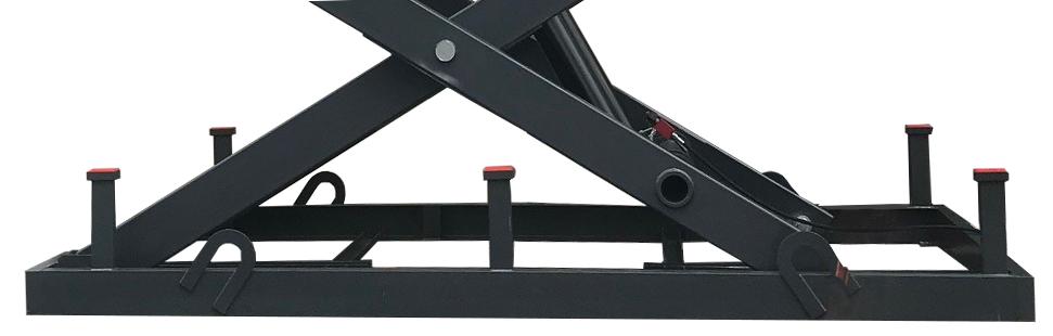
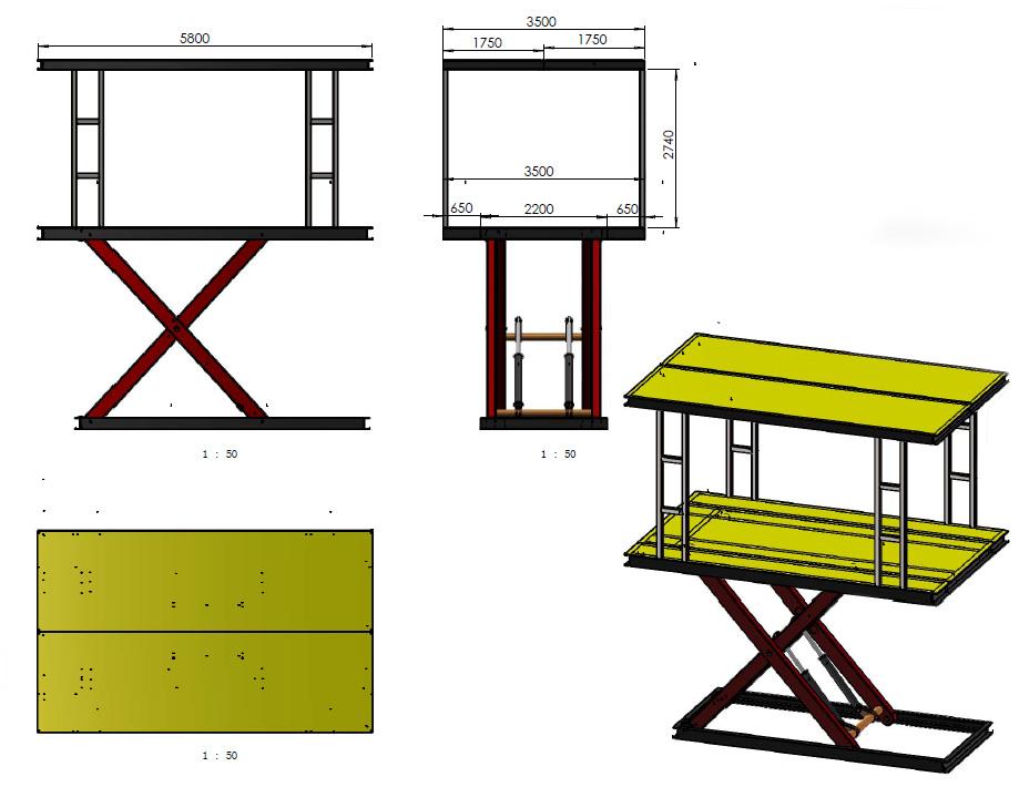
Thread the four wire ropes through the four lifting rings, then lift the assembly into the pit. Ensure the distance between the pit’s edge and the lift entrance is as small as possible without interfering with the hoistway on the canopy. The distance between the lifting rings and the pit sides should be equal on both sides.
Use a crane or other lifting device to lower the base of the Subterra into the pit. Once the position is correctly adjusted and verified, finish electrical and hydraulic connections and perform several test runs with the base and the first floor platform.
LIFTING RINGS
SUBTERRA
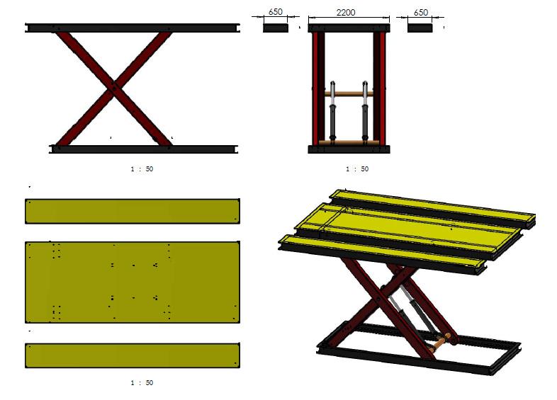
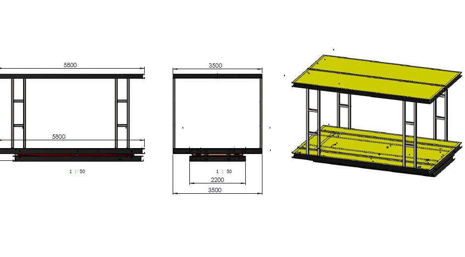
First, secure the two side platforms to the middle platform on the first floor using bolts and nuts. Then, check and adjust the positions of the middle platform and the side platforms. Attach them together securely.
SUBTERRA
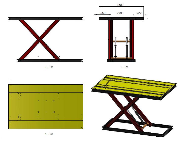
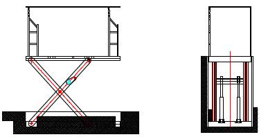
Raise the first-floor platform to ground level and secure it to the four support columns using bolts/nuts.

SUBTERRA
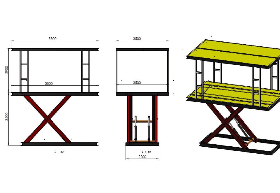
Place braces / supports across the span of the upper opening, lay canopy halves together ensuring they align perfectly, and secure and install the canopy platform. Set the lifting height to match the distance between the two platforms.

SUBTERRA
6
Perform multiple test runs on the entire equipment. Once you are confident that everything is functioning correctly, securely anchor the foundation bolts.
SUBTERRA
Electric Instructions
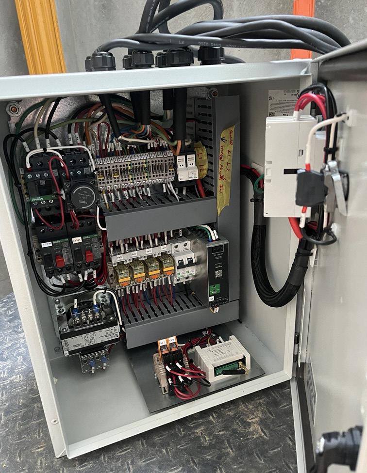
(1) The main control box should be installed near the pump station for convenient operation, ideally positioned on the first floor. For the second floor, auxiliary control panels should be mounted at the car’s entrance and exit point.
(2) One travel switch will be used on the first level.
SUBTERRA
8 9
Before loading the lift, the lift must be thoroughly checked, including the quality of the installation. Confirm that the mechanical transmission is free of jamming. The starting and stopping should occur without interference, abnormal sounds, or vibrations, and movement should be smooth and flexible. After this inspection, the Subterra can proceed with normal operations.
Test Running Operation Instruction
(1) Before regular use, the platform should be inspected by lifting it without any load. After this inspection, the Subterra can proceed with normal operations. (See above)
(2) The inspection should include checking the hydraulic pressure line and the electrical system. Ensure there are no leaks in the hydraulic circuit or joints, no exposed electrical wires, and no loose connections in the electrical system. Only after confirming that all items are in good condition can the Subterra be used regularly.
(3) When the platform lifts goods or vehicles, the center of gravity should be as close to the center of the work floor as possible.
SUBTERRA
10 Considerations
(1) Movement of goods or climbing is prohibited while the Subterra is loading or unloading goods.
(2) Only when the platform is lifted, secured, and all other operations of the Subterra are stopped, can other activities be carried out (such as loading or unloading goods, or parking or removing a vehicle from the platform).
(3) No operations involving excessive height or weight.
(4) Hydraulic oil should be kept clean and must not be contaminated with water or other impurities. Use ATF or AW32.
(5) If the Subterra fails to operate, the power source should be promptly disconnected.
(6) Operating faulty equipment is prohibited. Non-professionals are not permitted to remove or adjust hydraulic valve blocks and electrical components.
SUBTERRA
11
Mode of Control
Activate the power source. On the electrical control box, the “power” button indicator light illuminates. Press and hold the “up” button on either the call station or remote, causing the platform to ascend to its maximum height. Once the limit switch activates, it cuts off the power source, halting the platform’s movement.
Press and hold the “down” button on either the call station or remote to engage the solenoid valve, opening the valve core and initiating platform descent. During descent, releasing the “down” button can be used to halt the platform at any desired height. Upon reaching the minimum height, release the button on the call station or remote, stopping the platform.
12
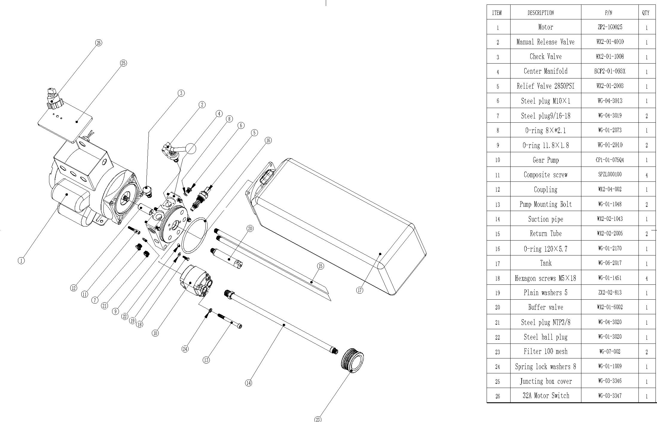
Parts Reference
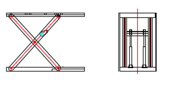
The Subterra can be designed with either a single group of struts or multiple groups of struts. However, as the main parts have the same names, we label the parts of the two groups of struts lift for clarity. (See next page)
SUBTERRA
Parts Reference
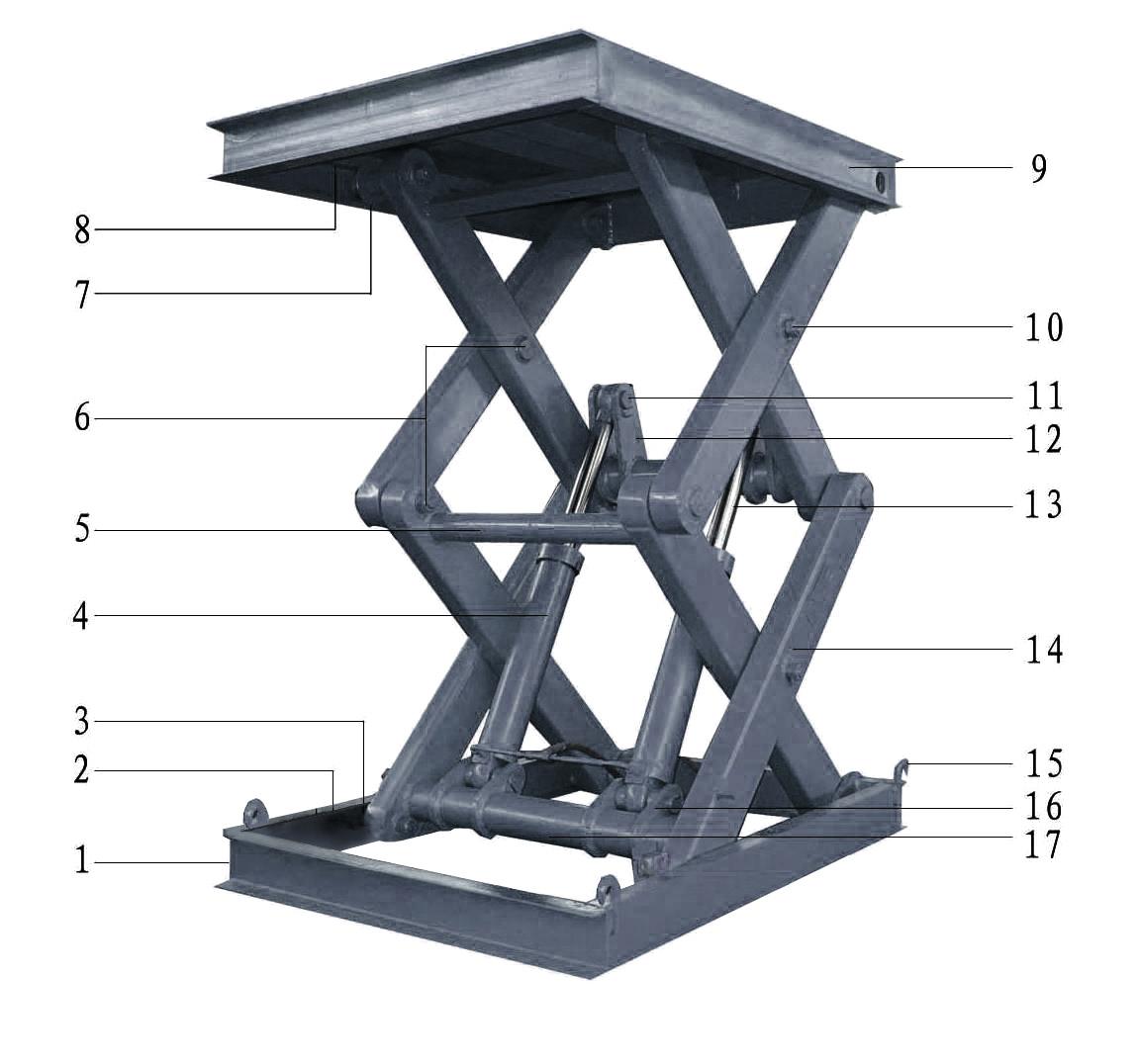
1.) Underframe
2.) Low Slide Way
3.) Low Idler Wheel
4.) Hydraulic Oil Cylinder
5.) Strut Bracket
6.) Arm Pin
7.) Top Idler Wheel
8.) Top Slide Way
9.) Platform
10.) Nut of Strut
11.) Cylinder Pin
12.) Top Support Arm
13.) Piston Rod
14.) Strut
15.) Lifting Hooks
16.) Low Support Arm
17.) Shaft
SUBTERRA
SUBTERRA
Troubleshooting
Problem
The pump station isn’t supplying oil, preventing the platform from lifting.
Reason
Power of electrical machine (25) is abnormal ( virtual connection or inversion)
There is no oil or not enough oil in the cylinder.
Oil filter (06) is blocked.
Normally closed valve (17) is dirty
The normally closed valve (17) and motor (25) are powered up simultaneously.
Gear pump (28) is old or damaged
Hydraulic oil is old or bad
Emergency bolt becomes loose
The joint between the oil suction pipe (07) and gear pump (08) becomes loose and leaks air
Solution
Connect the motor power correctly or regulate diversion.
Add hydraulic oil.
Clean the oil filter or replace hydraulic oil.
Tear down the normally closed valve and wash it with cleaning agent or paraffin.
Connect the lines correctly. When the motor (25) is electrified, the normally closed valve (17) should interrupt the power.
Replace the gear pump (08)
Change the hydraulic oil.
Tighten the emergency bolt (19)
Screw the oil suction pipe (07)
SUBTERRA
Troubleshooting Continued
Problem
Pump station doesn’t return oil and the platform cannot descend.
Reason
Power of normally closed valve (17) is not connected or there is not enough electricity.
The voltage and voltage type of normally closed valve coil (17b) is different from that of power.
The normally closed valve coil (17b) is damaged.
The normally closed valve nut (17c) is loose.
The normally closed valve (17) is jammed.
Solution
Connect the lines correctly and check voltage.
Check the voltage and it’s type (AC or DC). Supply the same voltage as the normally closed valve coil (17b).
Replace the normally closed valve coil (17b)
Screw normally closed valve nut (17c)
Problem
Reason
Platform Descends. Normally closed valve (17) or no-return valve (15) is dirty.
Remove the normally closed valve (17) and wash it.
Solution
Wash or replace the normally closed valve (17) and no-return valve (15).
Emergency bolt (19) loosens. Tighten the emergency bolt (19)
Hosepipe is leaking oil or oil cylinder is leaking inside.
Thoroughly check hospepipe and oil cylinder.
SUBTERRA
Troubleshooting
Problem
Lift is swaying when lifting or descending.
Continued
Reason
Solution
Normally closed valve (17) is dirty. Wash the normally closed valve (17).
Oil filter (06) is blocked or oil suction pipe (07) is loose.
Hydraulic oil is going bad or is not enough.
Power line is too long.
Wash oil filter (06) or tighten oil suction pipe (07).
Replace hydraulic oil or fill up hydraulic oil.
Shorten power line.
Emergency bolt (19) loosens. Tighten emergency bolt (19).
The descending speed is too slow or too quick.
The oil pipeline has an air leak, causing the oil cylinder to move erratically.
The cylinder is deformed, or the seal kit is too tight, causing the oil cylinder to move erratically.
Adjust flow speed control valve (23).
Check and repair oil pipeline.
Change the oil cylinder or seal kit.
SUBTERRA
Before performing any maintenance on the Subterra, verify that it is completely disconnected from power. The Subterra uses electrical energy; if your organization has Lockout / Tagout policies, make sure to implement them before performing any maintenance. If you come into contact with high voltage, you could be injured or killed.
Read your manual and understand how this equipment works before using, maintaining, or repairing. Routine maintenance and adjustments are the responsibility of the owner/employer and does not require trained lift service personnel. Replace worn, damaged or broken parts with original approved parts or with parts that meet or exceed the original specifications.
TO MAINTAIN YOUR LIFT:
▶ Daily: Keep the Subterra clean. Wipe up any spills, clean any dirt.
▶ Daily: Make a visual inspection of all moving parts and check for damage or excessive wear. Replace any damaged or worn parts before using the lift.
Do not use the Subterra if the cables are damaged or extremely worn. If a Vehicle is raised when you notice the damage or extreme wear, very carefully lower the Vehicle to the ground. When the Lift is on the ground, remove it from service, disconnect it from power, and make arrangements for repair.
▶ Daily: Visually inspect that the Safety Locks are in good operating condition. Do not use your Lift the Safety Locks are damaged or excessively worn.
▶ Weekly: Check all controls to make sure they are functioning normally.
▶ Weekly: Check all labels on the Subterra. Replace them if they are illegible or missing.
▶ Monthly: Lubricate the Posts. We recommend using white lithium grease or similar.
SUBTERRA
TO MAINTAIN YOUR LIFT CONTINUED:
▶ Monthly: Check Hydraulic Fluid Levels. Refill if low.
▶ Monthly: Check cable connections, bolts, and pins for proper mounting and torque.
▶ Monthly: Make sure all pivot arm pins are properly secure.
▶ Every 2 Months: Check all Anchor Bolts to make sure they are correctly torqued. If they are not, torque them to 85-95 ft lb.
▶ Every 3 Months: Inspect and lubricate the Wire Rope, Guide Rollers, Sheaves and Pins.
▶ Every 3 - 5 Years or as needed: Carefully check the Equalizing Cables every three to five years, or immediately if there are signs of damage or extreme wear. See Wire Rope Inspection and Maintenance for additional information.