objectives are to evaluate the technical and economical feasib ility of the process and to obtain essential technical data on PAN membrane UF treatment of secondary wastewater. A treatment system with a capacity of 500 tons per day product water was used on treatment of secondary wastewater in a WWTP in Beijing, Chi na.
Experimental Study Feed water The feed water used in the pilot rest was th e secondary wastewater from a WWTP in Beiji ng, China. It was the effluent fro m the secondary sedi mentation in an activated sludge system, consisting of screening, aeration and microbial deco mposition. T he secondary wastewater complies with Chinese Wastewater Discharge Standard (G B8978-1996) bur not Chinese Reclaimed Water Reuse Standard (CJ.25 .1 89). Without tertiary creacmenc, the secondary wastewater is not suitable for applicatio ns such as surface irrigation, car washing or toilet Aush due to excessive coliform, bacteria and suspended solids etc. The standard fo r water reuse and characteristics of the secon dary wastewater are shown in Table 2. Similar stan dards fo r Australian Authorities [l O] are also su mmarised in Table 5. UF pilot system Figure 1 illustrates the UF pilot setup, which consist of a feeding system, a prefiltration unit, a membrane UF unit, an automatic backwashing/clea ning system, and the associated control and piping system. T he secondary wastewater produced from a wastewater treatment plant was pum ped from the reservoir into the pre-treatment unit, where coarse particles (if any) in the feed water are removed by a sand fil ter, prior to entering into the membrane UF unit. Process Aow used for the pilot system was single-pass . After UF treatment, secondary wastewater is separated into two streams, i.e., the permeate (80%) collected for reuse and the concentrate (20%) fu rther sent back co che primary wastewater stream of the wastewater treatment plant. The membrane UF unit is the core unit affecting the performance of the UF pilot system. In chis study, the membrane UF unit co nsists of nine identical membrane modules, which are con figured into three module groups in parallel. Each module group is formed by connecting three modules in series. A schematic diagram of a single membrane module is shown in Figure 2. The membrane module (1 016 mm in length; 200 mm, i.e., 8 inch in diameter) is
58 AUGUST 2005
water
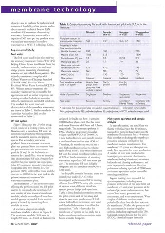
Table 1. Comparison among this work with th ree recent pilot tests [3,5,6] in th e literature.
Pilot plant capacity, in product water, tons/day Properties of hollow fibre membra ne module Module diameter, mm Module length, mm Fibre diameter (ID), mm Membrane area, m2 Membrane surface-to· volume ratio, m2/ m3 Membrane material MWCO (kDa) Flow pattern
This study
Decarolis et a/ (6]
Bourgeous eto/ [5]
Tchobonoglous eto/(3]
500
2.7*
3.4 · 5.7*
150*
200 1016 0.8 30
100 515 0.8 1.9
0.762 7.9
200 1800 0.9 45
923 PAN 70 Inside-out
470* PES 150 Inside-out
PS 100 Inside-out
796* PS 100 Inside-out
Total membrane modules used in UF system
Six (in Nine (in three groups, each paral lel) group has three modules in series)
Four (in porallel)
Mode of process flow
Single-poss
Dead-end
Single-pass/ recirculation
Feed water
Secondary
Tertiary
Secondary and/ Secondary/ Filtered Primary or Tertiary
Single-pass
* calculated from the original data provided in relevant references; · : information not available; PAN: polyacrylonitrile; PES: polyethersulphone; PS: polysulphone; MWCO: molecular weight cut-off. designed for inside-our Aow. It con tains 10800 hollow fibres, each fibre has inner and outer diameters of 0.8mm and 1.3mm, respectively. The membrane polymer is PAN, which has an average molecularweight cutoff (MWCO) of70,000 Da. T hese hollow fibres in one mod ule provide a coral membrane surface area of 30 m 2. T herefore, the membrane module has a very high membrane surface- to-volume ratio of 923 m 2/m 3• The whole membrane UF unit has a total membrane surface area of 270 m 2 for the treatment of secondary wastewater co produce 500 tons water per day. The membrane UF unit is highly integrated and is a compact unit (<1'> 240 x 3240 mm) . In the public domain literature, there are several pilot studies [3,4-6] which investigated applications of UF in creati ng effluent from WWT Ps using pilot systems of various scales, di fferent mem brane system, process design and operations. Table 1 lists a derailed compariso n among the pilot system used in this study and those in two recent publications [3,5,6], where hollow fibre membranes were used and detailed information is available for comparison. Table 1 shows that the membrane UF system in chis study has a higher membrane surface-to-volume ratio hence a smaller fo ocprin t.
Pilot system operation and sample analysis To start the system, the sand filter was Aushed with feed water for 30 minutes, followed by pumping feed water into the membrane filtration unit for a 10-minute Aush in order to discharge the membrane protective solutions prefi lled by the membrane module manufaccurer. T he membrane UF system was then put in to steady Aow operation fo r water production. A number of tests were conducted co investigate pre-treatment effectiveness, membrane fo uling behaviours, membrane backwash and cleaning performance, and most importantly membrane filtration performance during a period of 2500 hours continuous operations under controlled operating conditions. Regular readings were recorded for system operations, incl uding water pressures at the inlets of the sand filter and membrane UF unit, water pressures at the outlets of permeate and co ncentrate, Aow rates of feed water, permeate and concentrate, and water temperature. Water samples of different locations were periodically taken from the feed reservoir, the membrane UF inlet, the permeate and the concentrate for a series of quality analysis, including suspended solids (SS), biological oxygen demand for five days (BOD 5), chemical oxygen demands
refereed paper