

Marine VHF r adio operators Handbook VHF Handbook 2023
© Australian Maritime College 2014
ISBN 978-1-922708-17-5
First published for the Office of Maritime Communications, Australian Maritime College …May 2007.
Revised 2013.
Revised 2014.
Revised 2015.
Reprinted 2016.
Revised 2018.
Revised 2020.
Revised 2022.
Reprinted 2023.
This work is copyright. Apart from any use as permitted under the Copyright Act 1968, no part may be produced by any process without prior written permission from the Australian Maritime College (AMC).
Requests and inquiries concerning reproduction and rights should be addressed to: Australian Maritime College, The Manager, Office of Maritime Communications, Locked Bag 1394, Launceston Tasmania 7250
Email: amcom@amc.edu.au
Internet: www.amc.edu.au/industry/omc
This handbook is intended for the guidance of radio operators:
(a) on Australian vessels which are voluntarily fitted with marine Very High Frequency (VHF) radiotelephony and marine VHF radiotelephony with Digital Selective Calling (DSC) capability.
(b) on Australian vessels which are compulsorily fitted with marine VHF radiotelephony and marine VHF radiotelephony with digital Selective Calling (dSC) capability.
It is the recommended study guide for candidates undertaking the Short Range Operator Certificate of Proficiency (SroCP) examination.
Procedures and requirements outlined in the handbook are based on the International radio regulations formulated by the International Telecommunication Union (ITU), on provisions governing the use of radio transmitters in Australia laid down in the radiocommunications Act 1992 , and on radiocommunications station licence conditions set by the Australian Communications and Media Authority (ACMA).
Careful observance of the procedures covered by this handbook is essential for the efficient exchange of communications in the marine radiocommunications service, particularly when the safety of life at sea is concerned. Special attention should be given to those sections dealing with distress, urgency and safety.
It should be noted that no provision of this handbook, the International radio regulations, or the radiocommunications Act 1992 , prevents the use by a vessel in distress of any means at its disposal to attract attention, make known its position and obtain help.
Similarly, no provision of this handbook, the International radio regulations, or the radiocommunications Act 1992 , prevents the use by vessels engaged in search and rescue operations of any means at their disposal to assist a vessel in distress.
This study guide is based on extracts from the Marine radio operators Handbook 2013.
It also contains information about the Global Maritime distress and Safety System (GMdSS) marine communications techniques which are available for use by small vessels in Australia. The system uses advanced technology and automation to ensure that search and rescue authorities, as well as ships in the vicinity of an emergency, are alerted reliably and rapidly. Both satellite and terrestrial communications form essential components of the GMdSS.
The Australian Maritime College (AMC) acknowledges the contribution of ACMA, the Australian Maritime Safety Authority (AMSA), the Bureau of Meteorology, Telstra, and the Governments of the States and the Northern Territory and the McMurdo Group (chart image page 27) in the preparation of this Handbook.
Foreword
AUSTRALIAN MARITIME COLLEGE 1
2
IntroductIon to MarIne VHF ............. 4 operator requirements 4 radio Licence Information ............. 4 operators Qualifications 4 Marine VHF .......................... 4 General 4 Frequency of Marine VHF ............... 4 Frequency Spectrum ................. 4 range of VHF ...................... 5 VHF Marine radio equipment 6 Principle of operation 6 the Major Parts of radio equipment .6 General .6 Transceiver Controls . .. . . . . . . . . . . . . . . 6 Principle of operation................. 7 VHF Marine repeater Channels 7 Use of VHF Marine repeaters ........... 7 Stations for Marine communications 8 Limited Coast Stations ................ 8 Station Identification 8 operating Procedures .8 Authority of the Master .8 Priority of Communications .8 Radiotelephony Calling and Working Stations . 9 Protection of Channels ............... .9 Secrecy of Communications .9 watch Keeping .9 Silence Periods ................... .10 Unnecessary Communications .10 revision Questions ................... 11 callIng ProcedureS 12 routine calling Procedures 12 routine Calling 12 replying to Calls 12 repeating Calls ................... . 14 difficulties in establishing Contact with other Stations ................ . 14 distress calling Procedures 14 responsibility 14 Authority to Transmit a distress Call and Message 14 Channel for distress ................ 14 distress Alert ...................... 14 The distress Signal 14 The distress Call 14 The distress Message .............. . 15 distress Position Information 15 distress Traffic 16 Acceptance of distress Calls and Messages 16 Authority to Transmit a distress Acknowledgement 16 obligation to Acknowledge receipt of a distress Message 16 Acknowledgement of receipt of a distress Message .16 Control of distress Traffic . ........... . 17 resumption of Normal working .17 Transmission of a distress Message by a Station Not Itself in distress .18 The Urgency Signal ................ . 18 The Safety Signal .................. . 19 revision Questions .................. . . 20 dIgItal SelectIVe callIng (dSc) 21 General . .21 dSC-Capable equipment ............ .21 Station Identity. . . . . . . . . . . . . . . . . . . . .21 Transmission of a dSC Alert . .21 dSC Alert Formats .22 dSC distress Alert Procedures ........ .22 distress Position Information .22 dSC Alert Information ............... .22 Transmission of a dSC distress Alert .... .22 Test Transmissions ........ .10 Log Keeping .. . . . . . .. . . . .. . .10 Phonetic Alphabet and Figure Code .10 Control of Communications .10 General Care and Maintenance . . . . . . . . . 7 V VHF Marine Repeaters .. ............... .. 7 Four Digit VHF Channels .. . ....... . .10 MARINE VHF RADIO OPERATORS HANDBOOK
CoNTeNTS
repetition of distress Alerts . 23 Acknowledgement of a VHF dSC distress Alert 23 Cancellation of an Inadvertent dSC distress Alert 23 revision Questions 23 eMergency PoSItIon IndIcatIng radIo BeaconS: ePIrBs 24 general ......................... ...... 24 Local User Terminals .. ....... .. ...... . 24 Type of ePIrB ................. .. ... . 24 Identification of a 406 MHz ePIrB . 24 The CoSPAS-SArSAT International Satellite System 24 Methods of detection and location 25 The 406 MHz ePIrB .. 25 detection by Satellite ............ .. .. . . 25 activation of the 406 MHz ePIrB ........ . 26 Accidental Activation of an ePIrB ... . ...... 26 Servicing of ePIrBs ..... .. . ...... .. ... 26 Stowage of ePIrBs .... 26 revision Questions ................ .. . .. .. 26 SearcH and reScue tranSPonderS 28 revision Questions ................ ... .. . 29 Power SuPPlIeS .... 29 Maintenance Free Batteries .......... .... 29 Lead Acid Batteries 30 Battery Construction (courtesy of Battery Council International) . ................. . 30 Cell Voltage 30 Cell Capacity . 30 Battery Connection . .................. 30 Battery Hazards . ...................... 31 essential Battery Maintenance 31 Battery Cleanliness ................ ... . 31 electrolyte Level .................. ... . 31 Correct Charging ................. .... . 32 Measuring the Specific Gravity ...... .... .. 32 Measuring the on-Load Terminal Voltage .... 33 Loss of Capacity 33 Connection of Batteries during emergencies 33 revision Questions ............... .. . ... 33 Suggested Format for a radio logbook Page .34 MIScellaneouS .......... ........... ..... 35 table of transmitting channels in the VHF Maritime Mobile Band .......... ... .. .35 Marine VHF channels for use by Table 1. Professional Fishing Vessels Frequencies 40 Frequencies . . .. ............. . 40 Table 4. Port operations Frequencies ..... 41 Table 5. VHF Marine repeater Channels . 41 Note. Public Correspondence Channels 41 Phonetic alphabet and Figure code .... 42 Miscellaneous ........ ... . .... ..... . . 43 Figure Code. . . . . . . . . . . . . . . . . . . . .. . . . 43 Standard Marine communication Phrases 44 Message Markers............... . ... . 44 Internet websites for general Interest .48 contact details .............. . .. . ... ... 48 SEARCH AND RESCUE - GENERAL INFORMATION 27 Table 2. Commercial Vessel Frequencies . 40 Table 3. Yachts and Pleasure Vessels General 27 General 27 AIS-SART 27 General ............. . . ...... .. . ..... 26 General 28 SART Operation....... . . . . . ........... 28 Location Distances 29 AUTOMATIC IDENTIFICATION SYSTEM . .......... . . 27 . Ship Stations 40 revision Questions 28 AIS-MOB (Man Overboard) 28 E Examination Syllabus SROCP ... 46 AUSTRALIAN MARITIME COLLEGE 3 Positioning of the Sart 28
INTrodUCTIoN T o MArINe VHF
oPer ATor reQUIreMeNTS
radIo lIcence InForMatIon
Under theradiocommunications Act 1992 , the installation and operation of marine radio equipment aboard any Australian vessel must be authorised by a licence. In the case of marine VHF (Very High Frequency) equipment on board an Australian vessel this is authorised by the Radiocommunications (Maritime Ship Station - 27 MHz and VHF) Class Licence 2015. A copy of this class licence is available from the Federal Register of Legislation (https://www.legislation.gov.au). radio call signs are no longer issued by ACMA for marine VHF. However existing radio call signs may still be used.
The class licence does not authorise the operation of a ‘home base’. except in special cases, marine radio equipment in private residences will not be authorised by ACMA. The class licence allows for unqualified people to use VHF radios, provided they are supervised by a suitably qualified person.
oPeratorS QualIFIcatIonS
Under the above licence conditions, all operators of marine VHF equipment are required to possess the Short Range operator Certificate of Proficiency (SroCP) as issued by the office of Maritime Communications (oMC), a delegate of the AMC, on behalf of ACMA. As a minimum, vessels operating within the 12 nautical mile limit may obtain an Australian Waters Qualification (AWQ), which is a unit of competency (MARC059) in the Maritime Training Package. An AWQ is available from any Registered Training Organisation which has the Maritime Training Package on scope.
MArINe VHF general
National and International systems exist to provide prompt and effective search and rescue assistance to ships in distress. By complying with the following procedures, ship station operators can ensure that these systems continue to work effectively for the benefit of all mariners.
The transmission of false or deceptive distress, urgency or safety messages is strictly forbidden. extremely severe penalties, including imprisonment, exist under the radio communications Act 1992 , for any person found guilty of making such a transmission. All radiotelephony distress, urgency and safety calls and messages should be spoken slowly and clearly. The phonetic alphabet and figure code should be used if necessary. Use of the Standard Marine Communication Phrases is recommended in the case of language difficulties.
FreQUeNCY oF MArINe VHF
FreQuency SPectruM
The International Telecommunication Union (ITU) has allocated various bands of frequencies throughout the frequency spectrum for maritime use. The frequency spectrum is divided into eight bands, of which frequencies for maritime VHF use fall between 30 to 300 megahertz (MHz).
The VHF channel plan, as described in the International radio regulations, shows a total of 84 VHF channels available for marine use
65 channels are allocated for radiotelephone (voice communications).
32 of these channels operate in simplex mode (transmission and reception taking place on a single frequency).
33 of these channels operate in duplex mode (simultaneous transmissions and reception taking place on separate but
4
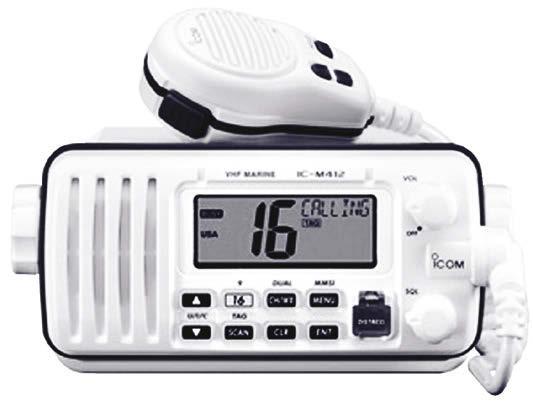
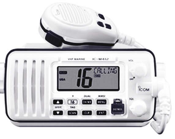
Fig. 1 Marine VHF transceiver
MARINE VHF RADIO OPERATORS HANDBOOK
paired frequencies).
1 (Channel 70) is for digital Selective Calling (dSC); and
2 (Channels 87B and 88B) are designated for Automatic Identification Systems (AIS) - AIS 1 and AIS 2 respectively.
For a complete list of VHF frequencies and uses, see the Table of Transmitting Frequencies on page 35.
range oF VHF
due to the propagation conditions of VHF, that part of the radio wave emitted from the transmitter (surface or ground wave) only follows the curvature of the earth’s surface for a limited distance. range of VHF is therefore considered as ‘short’ and dependent on the combined height of the transmitting and receiving antennas.
Generally speaking, the range of VHF is slightly greater than the visual line of sight of the combined antennas; the higher the antenna, the greater the range. during certain atmospheric conditions, particularly during the summer months, the ground wave may be refracted around the earth’s surface for a far greater range than would normally be expected of VHF. This phenomenon is known as ‘ducting’ and should not be regarded as normal.
2. 3. Small craft with handheld VHF Small craft with handheld VHF Approx. 5 nautical miles Small craft with handheld VHF Yacht with mast antenna 30 ft (9m) above sea level Approx. 10 nautical miles Yacht with mast antenna 30 ft (9m) above sea level Approx. 35 nautical miles Approx. 15 nautical miles Coast Station Coast Station
Approx. 60 nautical miles Large Vessel Coast Station repeater
1.
4. 5.
AUSTRALIAN MARITIME COLLEGE 5
Fig.
2
VHF MArINe rAdIo eQUIPMeNT
PrIncIPle oF oPeratIon
VHF marine equipment offers a communications range between vessels of up to 20 km (11 nautical miles) and between vessel and shore of 50 km (27 nautical miles), and possibly significantly greater:
• a safety service provided by limited coast stations operated by marine rescue and other organisations;
• the advantages of being relatively inexpensive, of providing the highest quality signal, of suffering least from interference caused by atmospheric or ignition sources, and
•of providing access to a radiotelephone service (not available in Australia); but
• the disadvantage of suffering blind spots behind cliffs, sand hills and heavy vegetation.
VHF marine equipment is suitable for small vessels remaining relatively close to the coast and within range of limited coast stations operating on VHF channels.
VHF marine equipment fitted with digital Selective Calling facilities may offer a single button distress facility and automatic watch keeping which are enabled only when programmed with a Maritime Mobile Service Identity (MMSI).
THe MAjor PArTS oF rAdIo eQUIPMeNT
general
Marine radio equipment operating in the VHF band is made up of three major parts:
•the power supply;
•the transceiver; and
•the antenna or aerial.
each part is dependent on the other. A fault in any one of the parts will not allow the equipment to function correctly. The power to operate the radio equipment may be supplied by the vessel's engine or from an independent battery.
The transmitter and receiver are combined into a single unit and commonly referred to as the ‘Transceiver’. The digital Selective Calling (dSC) unit may be further integrated with the transceiver.
The antenna for a marine VHF transceiver should be mounted as high as possible, preferably at the top of a mast, in order to give greater range, and is described as ‘A short vertical whip or rod antenna’. Ultra-violet radiation will cause fibreglassed whip antennas to deteriorate after many years of service to a point where moisture can penetrate the layers of insulation. This will seriously affect radiation efficiency and replacement or re-fibreglassing will be necessary.
tranSceIVer controlS
This section details the functions of important operator controls which may be found on marine VHF radio equipment. Not all will be found on each brand of equipment. Transceiver controls may be identified differently by individual manufacturers but will have the same purpose:
on/off and Volume control. often these functions are combined into a single control. It is used to turn the equipment on or off, and to adjust the level of signals coming from the loudspeaker.
Squelch control. This control allows the operator to stop the constant and annoying, internally generated, background noise from the receiver in the absence of an incoming signal. on VHF marine equipment, it is usually an adjustable control.
The correct setting is found by turning the control clockwise until the noise stops, but no further. If the control is adjusted beyond this point, the receiver will be desensitised and may not receive weak signals.
6
MARINE VHF RADIO OPERATORS HANDBOOK
channel Selector. This control is used to select the channel on which transmission or reception is required. dual watch (dw). This control will be found on the majority of VHF equipment. In operation it will permit the operator to keep a listening watch on a working channel and Channel 16. This is NoT to be confused with scanning desirable or selected VHF channels.
Scan. This control may be available on some brands of marine VHF equipment. Not to be confused with the dual watch control. This control may offer the operator the choice of scanning all the marine VHF channels, or selected channels.
Power Selector. This control varies the power of the transmitted signal. International regulations restrict the output power of Marine VHF to 25 watts maximum. on VHF marine equipment it may be marked ‘25w/1w’ (25 watts or 1 watt) or ‘high/low’. The use of more power than is required to communicate satisfactorily is a breach of the International radio regulations, may cause unnecessary interference, and drains the battery supplying the equipment at a faster rate. The correct transmitter power setting is generally referred to as “the minimum power to maintain reliable communication”.
International/uSa control. This control may be found on some VHF marine equipment. It is provided by the manufacturer to permit communications with stations in the USA which do not conform to the International VHF channel plan. It is important that this control is kept in the ‘International’ position at all times unless in the coastal waters of the USA. Some manufacturers of marine VHF supplied to Australian operators may have ‘International’ substituted by ‘Aus’.
general care and MaIntenance
Vessel owners should be aware that, on occasions, a power supply fuse will blow when the transceiver is malfunctioning or for no apparent reason. It is recommended that a supply of fuses of the manufacturer’s recommended value be carried on board. For safe keeping spare fuses could be contained in a suitable container.
V HF MArINe rePe ATerS
PrIncIPle oF oPeratIon
VHF communication range depends mainly on the height of the antennas of the transmitting and receiving stations. By using VHF marine repeater stations, the range of ship to ship, ship to shore and shore to ship communications can be significantly increased.
VHF marine repeaters are unmanned shore installations usually located at geographically high points. They are designed to transmit and receive simultaneously and will retransmit or ‘repeat’ all signals received. retransmitted signals can be received by any station listening on the repeater channel.
Limited coast stations operated by marine rescue organisations routinely monitor VHF repeater channels operating in their area.
Not all coastal areas of Australia are served by VHF marine repeaters.
VHF MarIne rePeater cHannelS
VHF marine repeaters operate in the duPleX* mode on channels 21, 22, 80, 81 or 82. (*Refer Page 43 for definition).
For their own safety, boat owners should ensure that they are familiar with the location and operating channel of their local repeater.
digital Selective Calling alerts using VHF must be confined to channel 70 and will not operate through repeaters.
uSe oF VHF MarIne rePeaterS
In most cases VHF marine repeaters are installed and maintained by marine rescue organisations as a service to mariners and are available for use by all licensed VHF ship stations. However, in order to minimise congestion, if direct
AUSTRALIAN MARITIME COLLEGE 7
ship to ship or ship to shore communications are possible on a non-repeater channel, this must be used in preference. repeater channels must not be used as ‘chatter channels’. Communications must be restricted to those concerning the movements of vessels and safety of vessels and persons. To discourage lengthy conversations, repeaters will incorporate an automatic time restriction of approximately thirty seconds.
If not apparent by monitoring, a ship station can gain an indication of its ability to access a repeater by momentarily depressing the microphone button. If a brief (approximately one second) burst or ‘tail’ of noise is heard from the loudspeaker when the button is released, then the vessel is activating the repeater. If a ‘tail’ is not heard, it is probable that the vessel is out of range of the repeater.
operators using VHF equipment equipped with an ‘International’ or ‘Aus’ channel switch should note that it is essential that the switch be in the ‘International’ or ‘Aus’ position to access repeaters.
S TATIoNS For MArINe CoMMUNIC ATIoNS
lIMIted coaSt StatIonS
Limited Coast Stations are stations on land established for the purpose of communicating with vessels at sea. These stations are primarily responsible for the safety of movement and operation of vessels within their local area. These stations are not licensed to handle public correspondence* .
There are no fixed hours for the radio service provided by Limited Coast Stations and many do not offer a continuous service. Hours of service are determined by local requirements or, in some cases, by State Government legislation. In the interests of safety, boat operators should familiarise themselves with services available to their area of operations. Limited Coast Stations generally fall into the category of marine rescue units, yacht clubs or fishing cooperatives.
StatIon IdentIFIcatIon
Transmission without identification is forbidden. All transmissions should be identified by the vessel’s name, any other identity (if available) or by other means, such as the Maritime Mobile Service Identity (MMSI).
oPer ATING ProCedUreS
National and International systems exist to provide prompt and effective search and rescue assistance to ships in distress. By complying with procedures in this chapter, ship station operators can ensure that these systems continue to work effectively for the benefit of all mariners.
All radiotelephony distress, urgency and safety calls and messages should be spoken slowly and clearly. The phonetic alphabet and figure code should be used if necessary. Use of the standard marine vocabulary is recommended in the case of language difficulties.
autHorIty oF tHe MaSter
A ship radio station and the service it provides are placed under the authority of the master, skipper, or the person responsible for the safety of the vessel.
PrIorIty oF coMMunIcatIonS
All radiotelephony communications have been prioritised as follows:
• Distress calls, messages and traffic are broadcast to all stations on distress channels;
• Urgency calls, messages and traffic may be broadcast to all stations or transmitted to an individual station on channels allocated for distress communications or on a working channel if the message is of an urgent medical request or repetition of an overdue vessel report.
*Public correspondence is any telecommunications which offices and stations, at the disposal of the public, must accept for transmission.
8
MARINE VHF RADIO OPERATORS HANDBOOK
• Safety calls and messages may be broadcast to all stations or transmitted to an individual station. The safety message will always be transmitted on a working channel. An acknowledgment is not expected for a safety broadcast.
• General or Routine communications will always be transmitted to an individual station on a working channel.
radIotelePHony callIng AND workIng cHannelS
Channels allocated to ship and limited coast stations are categorised as either calling or working channels:
• calling channels are for establishing the initial contact with other stations; and
• working channels are for the exchange of messages or conducting public correspondence by radiotelephone.
ProtectIon oF cHannelS
It is important that channels are used only for the purpose for which they have been assigned; e.g. channels authorised for calling are not used as working channels. Channels authorised for calling coast stations are not used for calling ship stations.
Secrecy oF coMMunIcatIonS
Article 17 of the ITU radio regulations prohibits the unauthorised interception of radio Communications not intended for the general use of the public.
Secrecy of communications does not apply to the broadcast of distress, urgency or safety traffic addressed to all stations.
watcHkeePIng
whilst at sea all vessels must maintain a listening watch on Channel 16 and render assistance to vessels in distress
Common Channel Channels MHz Communication withPurpose
Ch 77156.875 Ship stations
Ch 73 156.675 Limited coast and ship stations (Yacht & Pleasure craft)
Ch 72 156.625 Ship stations
Ch 71 156.575Limited coast and ship stations (Professional Fishing vessels)
Ch 70156.525All stations
Ch 67156.375All stations
Ch 16156.800All stations
Ch 13156.650 Limited coast and ship stations
Ch 6156.300 Ship and aircraft
General or routine communications
Calling and working
Calling and working
Calling and working
dSC distress, urgency, safety and routine alerting
distress, urgency and safety calling (supp. to Ch 16)
International radiotelephony distress, urgency, safety and calling channel
Intership Maritime Safety Information. May be used by Port Authorities for vessel harbour movements communications.
Co-ordinated Search and rescue (SAr). May be used by Port Authorities for tug to ship berthing communications
AUSTRALIAN MARITIME COLLEGE 9
SIlence PerIodS
The international regulations no longer require silence periods to be observed on the distress and calling frequencies. Those vessels that come under the Safety of Life at Sea regulations maintain a continuous watch on VHF DSC and a listening watch on Channel 16.
It is important to have the Marine VHF radio switched on, monitoring the International Distress Channel (Ch 16). And remember — when making a radio call, always listen first. That way, you won't interfere with anyone else who may be transmitting.
UNNECESSARY COMMUNICATIONS
Transmissions should be as brief as possible. Non-essential remarks, bad language and unnecessary conversations should be avoided. It is an offence under the Radiocommunications Act 1992, to use a transmitter in a manner that may cause a reasonable person to feel threatened or harassed.
teSt tranSMISSIonS
Test transmissions should be made on a working channel and kept to a minimum or avoided altogether on distress, urgency, or safety channels. If, after technical maintenance, or prior to departing port, it is necessary to test the radio equipment, approval from the nearest coast or limited coast station may be required.
logkeePIng
Operators should keep a record of all distress alerts and messages transmitted or received. Particulars should include the station or stations with which the messages were exchanged, the channels used and the date and times of the transmission and reception. Instead of an official log book, an exercise book could be drawn up. (See page 34).
PHonetIc alPHaBet and FIgure code
When experiencing difficulties with the exchange of radio communications, e.g. language difficulties, it may be necessary to exchange communications by the use of the Phonetic Alphabet, especially during distress communications situations. (See page 40).
control oF coMMunIcatIonS
During routine communications from ship to shore and ship to ship, the station being called ‘controls’ the communication process. If the communications is between a ship and a shore station, the shore station controls the communication process. In order that communications may be conducted efficiently, and with the minimum of delay, instructions issued by coast or Limited Coast Stations should be followed without delay.
FOUR DIGIT VHF CHANNELS
Due to increased need for marine VHF Channels for commercial use, ITU authorised and developed a new channel plan for the following VHF marine radio frequencies:
Channels 19, 20, 78 and 79 which were duplex have now been split into 8 simplex channels numbered 1019, 2019, 1020, 2020, 1078, 2078, 1079 and 2079.
This new channel plan took effect on January 1, 2017.
10
MARINE VHF RADIO OPERATORS HANDBOOK
reVISIoN QUeSTIoNS
1 } or the operation of Marine Is a radio Licence required f VHF transmitters?
2 } Is a radio operators certificate required for the operation of Marine VHF?
3 } what part of the VHF radio wave is used for communications purposes?
4 } Generally speaking, what range does the VHF have? Short, medium or long range?
5 } Generally speaking, what determines the range of marine VHF?
6 } where would you mount the VHF antenna?
7 } what is the purpose of the ‘Squelch’ control?
8 } what channels are monitored with the ‘dual watch’ control activated?
9 } what is the maximum transmitter power allowed for marine VHF?
10 } what is the minimum power permitted for marine VHF transmissions?
11 } what marine VHF channel is dedicated for VHF dSC?
12 } what marine VHF channel is reserved for the exchange of ship to ship marine safety information?
13 } what marine VHF channel maor ship to aircraft coordina y be used f ting search and rescue?
14 } what marine VHF channel is reserved for ship to ship general communications?
15 } what is the accepted minimum power setting for transmitting on VHF Ch 16?
16 } what is a marine VHF repeater station?
17 } what is the purpose of a Limited Coast radio Station?
18 } what services do Limited Coast radio Stations provide?
19 } what do you understand about station identification during transmission?
20 } How are radio transmissions identified?
21 } whose authority is the vessel’s radio station placed under?
22 } what is the order of priority of marine communications traffic?
23 } what marine VHF channel is used for distress calling and messages?
24 } what is the supplementary channel for channel 16?
25 } what is the SIMPLeX mode of transmission?
26 } when would the dUPLeX mode of transmission be used?
27 } what do you understand about confidentiality or secrecy of transmission?
28 } what is a calling channel?
29 } what is a working channel?
30 } what type of channel would a Maritime Safety Information message be broadcast on?
31 } what marine VHF channel should a listening watch be maintained on whilst at sea?
32 } Are Silence Periods required to be observed on marine radiotelephony channels?
33 } what information must be entered into the radio log book?
34 } what is the correct phonetic spelling of the word ‘MAGNILoQUeNT’?
35 } Generally speaking, what type of station controls the communication process?
AUSTRALIAN MARITIME COLLEGE 11
CALLING ProCedUreS
roUTINe CALLING ProCedUreS
routIne callIng
Before transmitting, the operator should listen for a period long enough to be satisfied that harmful interference will not be caused to communications already in place.
Marine VHF Channels established for calling purposes are not to be used for the exchange of routine messages.
when using radiotelephony channels in the VHF marine band and communications are good, the initial call would be as follows:
• the name and/or other identifying information of the station being called, spoken no more than three times;
• the words THIS IS;
• the name and/or other identifying information of the station calling, spoken no more than three times; (However when there is good clear communications without heavy radio traffic the call MAY be abbreviated to
-Name/identification of the station being called – once
-THIS IS
-Name/ identification of the calling station – twice)
• the purpose of the call;
• the suggested working channel for the exchange of messages; followed by
• the word OVER. (The invitation to reply)
an eXaMPle For a routIne SHIP to SHore InItIal call on cHannel 16:
Station called ………………Coast Guard
The words “this is”
The station calling (x2) THIS IS Cyclopse Cyclopse 503000100 on Ch 16, Position report oVer
rePlyIng to callS
The shore station reply would be:
AN EXAMPLE FOR A ROUTINE SHORE TO SHIP ACKNOWLEDGEMENT:
Station called
The words “this is”
Cyclopse 503000100
THIS IS
The station calling (x2) ………………..Coast Guard,………………..Coast Guard, Understood change to Channel 73 oVer
12
MARINE VHF RADIO OPERATORS HANDBOOK
The ship station reply would be:
AN EXAMPLE FOR A ROUTINE SHIP TO SHORE REPLY:
THIS IS Station called
………………..Coast Guard, ………………..Coast Guard
The words “this is”
The station calling (x2) Cyclopse 503000100
Received or Understood change to Channel 73 oVer
At this point both stations change to the suggested working VHF channel and the vessel initiates the call again.
Transmission without station identification is forbidden. once contact has been established, station identification may be shortened to just the station name:
an eXaMPle For a routIne SHIP to SHore InItIal call on tHe agreed workIng cHannel:
The words “this is”
Station called ………………Coast Guard THIS IS Cyclopse Cyclopse 503000100
The station calling (x2) on Ch 73 How do you read me? (what is my readability?) oVer
an eXaMPle For a routIne SHore to SHIP rePly :
The words “this is”
The station calling
tHe VeSSel contInueS:
The words “this is”
The station calling Sending Position
THIS IS
………………..Coast Guard
readability loud and clear (five by five) Go ahead with your position report oVer
THIS IS Cyclopse Position report Cyclopse 503000100 anchored in position ……………….etc. No further traffic oVer
AUSTRALIAN MARITIME COLLEGE 13
The coast station receives and acknowledges the position report:
tHe coaSt StatIon acknowledgeS receIPt oF tHe MeSSage:
The words “this is” THIS IS
The station calling ……………..Coast Guard
Acknowledgement received or Understood, your position report received, no traffic for your vessel, returning to Channel 16 and standing by, ………………….Coast Guard out (indicating the end of communications between the two stations)
At this point both stations return to monitoring Channel 16.
rePeatIng callS
If no immediate reply is received to the initial call, wait two minutes and repeat the call. After two calls, wait a further three minutes before calling again. At this point it may be necessary to call another station or to consider whether the required station is in range. restrictions with regard to repetition of calls do not apply to distress or urgency calls.
dIFFIcultIeS In eStaBlISHIng contact wItH otHer StatIonS
when a station receives a call and is not certain for whom the call was intended, it should not reply. Instead it should wait for a repetition of the call. when a station receives a call which is intended for it, but is uncertain of the caller, then the called station may reply requesting the identity of the calling station.
dISTreSS CALLING ProCedUreS
reSPonSIBIlIty
State and Territory police forces, using the resources of recognised volunteer marine rescue organisations, as well as their own water Police, co-ordinate most inshore boating emergencies.
autHorIty to tranSMIt a dIStreSS call and MeSSage
A distress priority message may only be sent on the authority of the master, skipper, or the person responsible for the safety of the vessel.
cHannel For dIStreSS
Channel 16 is the International Marine VHF channel for radiotelephony distress communication. In Australian waters, VHF Channel 67 is of supplementary channel to Channel 16.
dIStreSS alert
If the equipment is installed onboard, priority should be given to transmitting a dSC distress Alert on VHF Ch 70 followed by the distress call and message by voice on VHF Ch 16.
tHe dIStreSS SIgnal
The distress signal is the word MAYdAY. The transmission of the distress signal indicates that the vessel, or persons onboard that vessel, are in GrAVe ANd IMMINeNT dANGer and require immediate assistance.
tHe dIStreSS call
The distress call and message is broadcast to ALL STATIoNS, in the SIMPLeX mode of transmission. The radiotelephony distress call consists of:
14
MARINE VHF RADIO OPERATORS HANDBOOK
•the distress signal MAYDAY, spoken three times;
•the words THIS IS;
• the name and any other identity of the vessel in distress, spoken three times.
tHe dIStreSS MeSSage
The radiotelephony distress message consists of:
•the distress signal MAYDAY;
• the name and any other identity of the vessel in distress;
• particulars of its position;
• the nature of the distress, the kind of assistance desired;
• any other information which may facilitate rescue; followed by
•the word OVER, the invitation to respond.
The distress call and message may be repeated as often as necessary until an answer is received.
If no answer is received on distress channels, the message should be repeated on any other available channel where attention might be attracted, e.g. a relevantVHF marine repeater channel.
eXaMPle oF a coMPlete dIStreSS call and MeSSage:
The VHF dSC distress Alert, if facility fitted, followed by:
dIStreSS call
distress signal (x3)
words “this is”
Station calling (x3)
dIStreSS MeSSage
distress signal
Name/MMSI
Position
Nature of distress
other information
(If time permits)
Mayday, Mayday, Mayday
THIS IS
SCAMP SCAMP SCAMP 503000123
(For vessels equipped only with VHF, a ship station licence is not required and therefore a radio call sign will not have been allocated).
Mayday
SCAMP 503000123
50 NAUTICAL MILeS dUe eAST FroM PoINT dANGer
SINKING AFTer STrIKING SUBMerGed oBjeCT.
eSTIMATe FUrTHer 15 MINUTeS AFLoAT. 20 MeTre MoTor CrUISer red HULL
wHITe SUPerSTrUCTUre 4 PerSoNS oNBoArd ePIrB ACTIVATed
oVer
dIStreSS PoSItIon InForMatIon
Preference should be given to indicating the position by latitude and longitude (degrees and minutes and decimal points of a minute if necessary, North or South, east or west); or true bearing and distance (the unit of distance should always be specified, for example, nautical miles or kilometres) from a known geographical point (for example 045 degrees true from Point danger, 24 nautical miles); or a precise geographical location (for example, in the case of a vessel running aground). where latitude and longitude are not used, care must be taken to ensure that the position given cannot be confused with any other place or geographical point.
If afloat and drifting, the rate and direction of drift could be stated in the distress message.
AUSTRALIAN MARITIME COLLEGE 15
dIStreSS traFFIc
All communications relating to the immediate assistance required by the vessel in distress, including search and rescue communications and on-scene, should use the distress signal MAYdAY to precede each call and message.
accePtance oF dIStreSS callS and MeSSageS
The obligation to accept distress calls is absolute and they must be given priority over all other communications.
autHorIty to tranSMIt a dIStreSS acknowledgEMent
A distress acknowledgement may only be sent on the authority of the master, skipper, or the person responsible for the safety of the vessel.
oBlIgatIon to acknowledge receIPt oF a dIStreSS MeSSage
Ship stations that receive a distress message from another vessel which is, beyond any possible doubt, in their vicinity, should immediately acknowledge receipt. However, in areas where reliable communications with a coast station is practicable, ship stations should defer this acknowledgement for a short interval to allow the coast station to acknowledge receipt.
Ship stations which receive a distress message from another vessel which, beyond any possible doubt, is not in their vicinity should defer their acknowledgement to allow vessels nearer to the distressed vessel to acknowledge without interference.
Ship stations which receive a distress message from another vessel which, beyond any possible doubt, is a long distance away, need not acknowledge receipt unless this distress message has not been acknowledged by any other station.
when a ship station hears a distress message which has not been acknowledged by other stations, but is not itself in a position to provide assistance, it should acknowledge the call and then take steps to attract the attention of a coast station or vessels which might be able to assist.
ACKNOWLEDGEMENT OF RECEIPT OF A DISTRESS MESSAGE
Acknowledgement of receipt of a distress message by a vessel or coast station should be made in the following way: y;
• the distress signal Mayda
• the name and any other identity of the station sending the distress message, spoken three times
• the words THIS IS
• the word receIVed;
• the distress signal Mayda
• the name and any other identity of the station acknowledging receipt, spoken three times; y
eXaMPle oF an acknowledgEMent or receIPt oF a dIStreSS MeSSage By a Mayday
dIStreSS traFFIc distress vessel (x3)
The words “this is” Station calling (x3)
THIS IS SHIP StatIon
tHe acknowledgeMent receIVed Mayday
• OVER oVer
16
MARINE VHF RADIO OPERATORS HANDBOOK
As soon as possible after this acknowledgement a ship station should transmit the following information:
• its position;
• the speed at which it is proceeding; and
• the approximate time it will take to reach the distress scene.
control oF dIStreSS traFFIc
The control of distress traffic is the responsibility of the vessel in distress. However, this station may delegate the control of distress traffic to another vessel, or coast station.
The ship in distress or the station in control of distress traffic may impose silence on any or all stations interfering with distress traffic by sending the instruction S SEELONCE MAYDAY
This instruction must not be used by any station other than the ship in distress, or the station controlling distress traffic.
eXaMPle oF a MeSSage By tHe dIStreSS VeSSel or tHe control StatIon IMPoSIng SIlence:
dIStreSS traFFIc: Mayday
Addressed to: (x3)
The words “this is”
Station calling (x3)
The signal:
All stations, all stations, all stations
THIS IS
(Name of station in control of distress tra )ffic Seelonce Mayday
Any station which has knowledge of distress traffic and cannot provide assistance should continue to monitor the traffic until such time that it is obvious assistance is being provided.
Any station which is aware of distress traffic, and is not taking part in it, is forbidden to transmit on any channel which is being used for that traffic.
Ship stations not involved in the exchange of distress traffic may, while continuing to monitor the situation, resume normal radio service when distress traffic is well established and on the conditions that distress traffic channels are not used and no interference is caused to distress traffic.
reSuMPtIon oF norMal workIng
when distress traffic has ceased on a channel that has been used for distress traffic, the station that has been controlling that traffic should transmit a message addressed to all stations indicating that normal working may be resumed. The message announcing resumption of normal working should take the following form:
•the distress signal MAYDAY;
•the call ALL STATIONS, spoken three times;
•the words THIS IS;
• the name and any other identity of the station sending the message;
•the time the message originated;
• the name and any other identity of the vessel which was in distress;
•the words Seelonce Feenee.
AUSTRALIAN MARITIME COLLEGE 17
eXaMPle oF tHe dIStreSS VeSSel or tHe control StatIon adVISIng
reSuMPtIon oF norMal workIng on tHe dIStreSS cHannel: Mayday
dIStreSS traFFIc:
Addressed to: (x3)
The words “this is”
The station calling (x3)
Time of the message
The identity of the distress vessel:
All stations, all stations, all stations
THIS IS
(Name of calling station)
…... U UTC*
The signal: (Name of distress vessel) Seelonce Feenee
*C Co-ordinated Universal Time (UTC), or may be in local time
tranSMISSIon oF a dIStreSS MeSSage By a StatIon not ItSelF In dIStreSS
A ship or coast station which learns of a vessel in distress may transmit a distress message on behalf of that vessel when:
• the distress vessel cannot transmit a distress message; or
• although not in a position to assist, a vessel in the vicinity has not heard an acknowledgement; or
• the master, skipper, or the person responsible for distress communications, or a limited coast station considers that further assistance is necessary.
eXaMPle oF a dIStreSS MeSSage receIVed and tHen relayed By anotHer StatIon
VHF dSc dIStreSS relay alert followed by spoken message.
Ma Mayday relay call (X3): yday relay, Mayday relay, Mayday relay
The words “this is”
Station calling (x3)
THIS IS
(Name of relay station) ……………......................
tHe Mayday MeSSage: (repeat of original Mayday message) ……………...................... oVer
eXaMPle oF a dIStreSS MeSSage created
and BroadcaSt By a StatIon on
BeHalF oF a SHIP StatIon
VHF dSc dIStreSS relay alert followed by spoken message.
Ma Mayday relay SIgnal (X3): yday relay, Mayday relay, Mayday relay
The words “this is” THIS IS
Calling Station (x3)
(Name of Coast Station) ……………......................
tHe Mayday relay MeSSage: Mayday relay, name of vessel in distress, position, nature of distress and any other information (persons onboard) oVer
tHe urgency SIgnal
The urgency signal consists of the words PAN PAN, and indicates that the caller has an urgent message to transmit concerning the safety of the vessel, aircraft or person. It has priority over all other communications except distress.
18
MARINE VHF RADIO OPERATORS HANDBOOK
The urgency signal may be used to precede a message concerning a man overboard where urgent assistance is required to locate that person.
The urgency message may only be sent on the authority of the master, skipper or person responsible for the safety of the vessel. The urgency message may be broadcast to all stations on the distress, urgency or safety channel (Ch16) or to an individual station on a working channel after the announcement on Ch16.
A lengthy urgency message requesting medical advice or assistance, or repetition of a message relating to a vessel overdue would also be transmitted on a working channel. The caller may request an acknowledgement for the reception of such a message.
eXaMPle oF tHe BroadcaSt oF an urgency call:
Urgency signal (x3) Pan Pan, Pan Pan, Pan Pan
Addressed to: (x3)
The words “this is”
The station calling (x3)
Urgency message
eXaMPle
………………Coast Guard
THIS IS
(Name of calling station)
request urgent medical assistance, crew member sustained a broken leg, suggest change to channel 67 oVer
oF tHe BroadcaSt oF an urgency call:
Urgency signal (x3)
Addressed to: (x3)
The words “this is”
The station calling (x3) Pan Pan, Pan Pan, Pan Pan
Urgency message
All stations, all stations, all stations
THIS IS
(Name of calling station)
In position ………………… broken rudder, no steerage request tow to shore oVer
The urgency situation should be cancelled by the station of origin once the urgency situation is finalised.
tHe SaFety SIgnal
The safety signal consist of the word SeCUrITe (pronounced SAY-CUre-e-TAY), and indicates that the caller is about to broadcast a message concerning an important navigational or weather warning. It has priority over all other messages except distress or urgency messages.
The safety warning is announced on the distress, urgency or safety channel (Ch 16) with the safety message being broadcast on a working channel. An acknowledgement is not required.
eXaMPle oF tHe BroadcaSt oF a SaFety call FroM a VeSSel:
Safety signal (x3)
Addressed to: (x3)
The words “this is”
The station calling (x3)
Safety alert
SecurIte, SecurIte, SecurIte
All stations, all stations, all stations
THIS IS
(Name of calling station)
Navigation warning listen on Channel 13
AUSTRALIAN MARITIME COLLEGE 19
Safety signal (x3)
Addressed to: (x3)
The words “this is”
The station calling (x3)
Safety alert
SecurIte, SecurIte, SecurIte
All stations, all stations, all stations THIS
(Name of calling station)
Navigation warning listen on Channel 72
R EVISION QUESTIONS
3 37} What should the caller do prior to transmission?
3 38} What should you do next if you are unsure of the identity of the calling station?
3 39} What should you do next if you are unsure of the identity of the station being called?
4 40} What does the word 'OVER' indicate during radiotelephony communications?
4 41} What does the word 'OUT' indicate during radio telephony communications?
4 42} What should yo do next if your routine call has not been replied to?
4 43} What should you do next if your distress call and message have not been acknowledged?
4 44} To whom is a routine or general message addressed?
4 45} What type of channel should be used for the exchange of routine or general messages?
4 46} What marine VHF channel is used for radiotelephony distress communications?
4 47} What is the radiotelephony distress signal?
4 48} What is the definition of the distress signal?
4 49} Whose authority is required before using the distress signal?
5 50} To whom is the distress broadcast addressed?
5 51} What transmission mode is used for a distress broadcast?
5 52} What is the sequence of a distress call?
5 53} What is the first word of a distress message?
5 54} What is the correct sequence for a distress message?
7 72} Is an acknowledgement expected for a safety broadcast? 3 36} What marine VHF channel may be used for routine or ship to ship general communications?
55} What is your obligation with respect to accepting distress traffic?
5 56} What should you do next on hearing, or receiving, a distress alert?
5 57} Whose authority is required before acknowledging a distress alert?
5 58} What is the expression used to acknowledge a distress call and message by radiotelephone?
5 59}
60}
61}
What word is used to precede all radiotelephony distress traffic?
What station controls radiotelephony distress traffic?
What expression may be used, by any station to impose silence on the distress channel?
6 62} What expression is used, by the station in control of distress traffic, to advise that normal traffic may now continue on the distress channel?
6 63} What is the radiotelephony urgency priority signal?
6 64} What is the definition of the urgency priority signal?
6 65} What type of message is preceded by the urgency priority signal?
6 66} What channel is used for the transmission of an urgency message?
6 67} To whom is the urgency message addressed?
6 68} What is the radiotelephony safety signal?
6 69} What is the definition of the safety priority signal?
7 70} What type of message is preceded by the safety signal?
7 71} What channel is used for the transmission of a safety message?
20
oF tHe BroadcaSt oF a SaFety call FroM a coaSt StatIon:
eXaMPle
IS
MARINE VHF RADIO OPERATORS HANDBOOK
SeLeCTIVe CALLING (dSC)
general
digital Selective Calling (dSC) was first introduced to mariners with the commencement of the Global Maritime distress and Safety System (GMdSS), primarily for vessels compulsorily equipped with marine radio communications equipment.
Marine VHF dSC operates on Channel 70. The dSC alert is transmitted via the VHF unit on Channel 70, and is comparable to a telephone paging system. The dSC is designed, in many ways, to replicate what an operator may say when operating radiotelephony equipment. dSC is also designed to take the place of an operator continuously monitoring the International distress channel 16. However, regulatory authorities have decided that operators of marine VHF should, when at sea, continue to monitor Channel 16 indefinitely.
dSc-caPaBle eQuIPMent
VHF transceivers with dSC facilities are available for small vessels. Many marine VHF units have the dSC facility inbuilt with the ability to interface a Global Position System (GPS) receiver to the dSC, in order to ensure accurate and up to date position information that will be automatically included in a distress alert. dSC equipment may also offer the operator the facility to manually update vessel position information.
VHF marine radio equipment fitted with Digital Selective Calling may offer a single-button distress facility and automated watch keeping.
StatIon IdentIty
In order to use dSC techniques, the VHF dSC controller must be permanently programmed with a unique nine digit identification number known as a Maritime Mobile Service Identity (MMSI). The MMSI is issued by AMSA upon request. http://amsa.gov.au/mmsi/
The first three digits, known as the Maritime Identity digits (MId) of the MMSI indicate the country of registry.
The MId for Australian vessels is 503 and is followed by six digits uniquely identifying the vessel itself.
Coast stations are identified by the first two digits of the MMSI as two zeros, i.e. 00, followed by the MId, followed by four digits identifying the station itself: 00503xxxx
other types of stations have been allocated prefixes for their MMSI's, as shown in the table below: 503xxxxxx;
• Vessel
•Group
•SAR Aircraft111503xxx; and 0503xxxxx;
• Aids to Navigation 99503xxxx. (Lightships etc)
•Coast Station00503xxxx;
tranSMISSIon oF a dSc alert
The dSC transmission is a brief burst of digital data, typically 0.5 seconds in duration on Channel 70. This channel is protected and should not be used for any other type of transmission.
dSC is a semi-automated method of establishing the initial contact between stations. once the initial contact has been made, subsequent radiotelephone communications should continue on any one of the marine VHF channels, depending on the priority of the service required.
dIGI
TAL
gPS dSc VHF Power Supply
AUSTRALIAN MARITIME COLLEGE 21
Fig. 3 - dSc Block diagram
DSC ALERT INFORMATION
The dSC alert contains the following information as digitised data:
•the identity of the calling station (MMSI);
• the station being called (a specific station or all stations);
• the priority of the alert - distress, urgency, safety or routine; and
• the position of the calling station and an indication of when the position was last updated.
DSC ALERT FORMATS
The International dSC system provides for the following types of alerts:
•Distress alerts – implicitly addressed to All Stations.
• Distress alert acknowledgement – normally transmitted by coast stations or limited coast stations only. May be used by ship stations under specific circumstances.
• Distress alert relay – normally transmitted by coast stations or limited coast stations only. May be used by ship stations under specific circumstances.
• All stations – used to alert all stations that a distress, urgency or safety alert is about to follow.
• Selective or single station – used to alert an individual station that an urgency, safety or routine alert is to follow.
DSC DISTRESS ALERT PROCEDURES
As with a radiotelephony distress call, the dSC distress alert may only be sent on the authority of the master, skipper or person responsible for the safety of the vessel. The dSC distress alert also indicates that the vessel or persons onboard that vessel is in grave and imminent danger and requests immediate assistance. All stations receiving a dSC distress alert must immediately cease all transmissions capable of interfering with distress communications.
DISTRESS POSITION INFORMATION
with GPS interfacing, position information will automatically be inserted into the distress alert and give an indication of when that position was last updated.
Following the International ITU radio regulations:
If the position is not updated within 23.5 hours, the section indicating Latitude will show five 9s and the section indicating Longitude will show five 9s. The section indicating the time of the position will show four 8s. Some manufacturers will insert a series of asterisks (*) to replace the digits of position and time information if the position has not been updated. on vessels compulsorily fitted with dSC it may be necessary to update the position information no later than four hours, with a warning system to indicate that the position requires updating. therefore the position and time at which it was last updated will always be indicated.
TRANSMISSION OF A DSC DISTRESS ALERT
operators of VHF dSC may have the option to transmit the distress alert by:
•a dedicated Distress alert button;
•editing of the distress alert menu; or
• selection of the distress priority from a standard menu, if provided.
22
MARINE VHF RADIO OPERATORS HANDBOOK
Some dSCs may offer the operator the option of selecting the distress priority from a transmission menu with a further option of editing the distress alert by selecting and transmitting the nature of the distress situation e.g. ‘on fire’, ’collision’ or ‘abandoning ship’.
However, the primary function of a distress alert is to advise all stations of the distress situation and the location of the distress vessel.
rePetItIon oF dIStreSS alertS
The acknowledgement of a VHF distress alert should be anticipated from a Coast or Limited Coast Station. However, if an acknowledgement is not received for the dSC distress alert then it will automatically be repeated at approximately four minute intervals for five transmissions.
acknowledgeMent oF a VHF dSc dIStreSS alert
Ship stations receiving a distress alert from another vessel should take note of the contents and immediately listen on Channel 16 for any radiotelephony MAYdAY traffic that should follow.
If a MAYdAY is received on VHF Channel 16 it should be acknowledged using the standard radiotelephony procedure. once the dSC distress acknowledgement is received the repeat dSC distress alert is cancelled.
An acknowledgement is not required if the receiving vessel is unable to assist. Ship stations receiving a dSC distress alert from another vessel may acknowledge by dSC if:
• mayday traffic has not been heard on Channel 16 within 5 minutes;
• no other stations have been heard communicating with the vessel in distress; and
•the DSC distress alert is repeated.
cancellatIon oF an InadVertent dSc dIStreSS alert
In the event of an accidental transmission of a dSC distress alert, the transmitting station should immediately:
• switch off the VHF transceiver (this will block any transmission repeats of the DSC alert which would continue until an acknowledgement is received);
• switch on the VHF transceiver and select Channel 16; and then
• broadcast an ‘All stations’ call, indicating the vessel’s name, MMSI, time of the accidental alert and an expression of cancellation of the distress alert.
re VISIoN QUeSTIoNS
73 }
7 74 } what information is included in all VHF dSC alerts?
How is a VHF dSC receiver controller identified?
7 75 } what Australian organisation issues VHF dSC identity
7 76 }
7 77 }
7 78 }
7 79 } numbers?
what do the first three digits of a vessel’s MMSI indicate?
what type of station will be issued with an MMSI commencing with 0?
what type of station will be issued with an MMSI commencing with 00?
what other navigational equipment is highly recommended to be interfaced with the dSC unit?
8 80 } what marine VHF channel is used for dSC alerting?
81 } what should you do next after receiving a VHF dSC distress alert?
8 82 } How would you acknowledge a VHF dSC distress alert?
8 83 } what information is included in all VHF dSC distress alerts?
8 84 } on receiving a VHF dSC distress alert, should you acknowledge by dSC?
8 85 } what happens if a dSC distress alert is not acknowledged immediately?
8 86 } To whom is a routine priority alert addressed?
8 87 } How many digits does a MMSI number have?
8 88 } what should the operator do next if a dSC distress alert has been accidentally transmitted?
AUSTRALIAN MARITIME COLLEGE 23
e MerGeNCY PoSITIoN INdICATING r AdIo BeACoNS; ePIrB s
GeNerAL
ePIrBs are authorised under a class licence and as such do not require an individual radio communications licence. An ePIrB is described as a small, self-contained, battery-operated radio transmitter which is both watertight and buoyant. The signal from an ePIrB is a ship to shore distress alert.
The essential purpose of an ePIrB is to assist in determining the geographic position of survivors in search and rescue operations. The ePIrB should not be considered as an alternative to an approved marine radio transceiver. operation of the ePIrB should be a simple two step action and, once switched on or activated, should not be switched off until rescue has been completed. International radio regulations state that the ePIrB battery should be capable of supplying power to the ePIrB for a minimum of 48 hours.
The ePIrB signal is designed to be received by the Cospas-Sarsat System satellites. The Cospas-Sarsat System provides distress alert and location information to search and rescue (SAr) services throughout the world for maritime, aviation and land users in distress.
local uSer terMInalS
Stations established on land for the purpose of receiving signals from the Cospas-Sarsat satellites are known as Local User Terminals (LUTs).
There are two LUTs in Australia, one located at Albany, in western Australia, and another at Bundaberg, Queensland, both of which are linked to the rescue Coordination Centre (rCC) Canberra. Another LUT located at wellington, New Zealand, is also linked to rCC Canberra.
tyPe oF ePIrB
There is currently only one type of ePIrB available for use by all vessels. 406.025 MHz or 406.037 MHz. It is commonly referred to as the 406 MHz ePIrB.
It operates on the UHF frequencies of
IdentIFIcatIon oF a 406 MHz ePIrB
Purchasers of a 406 MHz ePIrB are required to complete a registration form which is lodged with the Australian Maritime Safety Authority, Canberra. each 406 MHz ePIrB has a unique identity code which is transmitted as part of its digitised signal and indicates its country of registration. rCCs around the world can therefore identify the vessel to which an activated ePIrB belongs.
tHe coSPaS-SarSat InternatIonal SatellIte SySteM
The Cospas-Sarsat satellite system is an international consortium of The United States of America, Canada, France and russia designed to locate an activated ePIrB operating on a 406 MHz frequency. The system uses low earth orbiting satellites, leoS, each making a complete low earth Polar orBIt at between 700 and 1000 km altitude, in approximately 100 minutes. At least one of these orbiting satellites is in line of sight of any point on the earth’s surface at a maximum interval of three hours. orbiting satellites in the Cospas-Sarsat system have a viewing range, or footprint, approximately 2000 km either side of its track across the surface of the earth.
The system also use satellites that are geo StatIonary, in fixed positions, some 36,000 km above the equator. The International Cospas-Sarsat Programme initiated the development of the Medium-altitude Earth Orbiting Satellite System for Search and Rescue (MEOSAR system) in 2004, with SAR repeaters placed on the satellites of the Global Navigation Satellite Systems (GNSS) of Europe (Galileo), Russia (Glonass) and the USA (GPS). Early operational capacity (EOC) for the MEOSAR system was declared in December 2016 and full operational capacity (FOC) of the system is anticipated in 2020. MEOSAR complements the existing LEOSAR (satellites in low-altitude orbits) and GEOSAR (satellites in geostationary orbit) systems, and will eventually replace the LEOSAR system.
24
MARINE VHF RADIO OPERATORS HANDBOOK
The large number of MEOSAR satellites that will be in orbit when the system is fully operational will allow each distress message to be relayed at the same time by several satellites to several ground antennas, improving the likelihood of quick detection and improving the accuracy of the location determination.
MeTHodS oF deTeCTIoN ANd LoCATIoN
tHe 406 MHz ePIrB
The 406 MHz ePIrB transmits a short burst of digital data on the frequencies of 406.025 MHz, 406.028 MHz and 406.037 MHz. This burst of data is typically a 5 watt signal of 0.5 of a second duration every 50 seconds.
The 406 MHz ePIrBs manufactured to Australian specifications also transmit on 121.5 MHz for aircraft homing purposes. Transmission on 121.5 MHz simultaneously radiates a continuous series of distinctive descending tones which contain no station identification.
The 406 MHz ePIrB is therefore capable of being detected by:
• aircraft within range AND monitoring the civil aviation frequency of 121.5 MHz; and
• satellites operating in the Cospas-Sarsat system.
detectIon By SatellIte
Satellites monitoring 406.025 MHz can receive the digitised burst of data and relay the signal back to earth in the ‘real time’ mode, as long as the ePIrB and LUT are in the satellite footprint at the same time.
Because signals from a 406 MHz ePIrB are in a digitised form, they can also be stored in the satellite’s memory. As the satellite’s path brings it into view of a LUT, information, including time of first detection, is retrieved from the satellite’s memory and relayed down to the LUT. This information is processed and passed to a rescue co-ordination centre, providing both an alert and a position. This is said to be in the ‘global’ mode. Position accuracy is better than 5 km (2.7 nautical miles). .
ePIrBs operating on 406.028 and 406.037 MHz operate in a similar manner to the 406.025 MHz ePIrB. However, the 406.028 and 406.037 MHz ePIrBs also have an inbuilt Global Position System (GPS) unit installed. once activated, the GPS unit can receive position information from GPS satellites and within 5 minutes include that information in the burst of data that is received by the LUT, which is then relayed to the rCC. Position accuracy is within 150 metres of the activated ePIrB.
AUSTRALIAN MARITIME COLLEGE 25
LUT
Fig. 4 - Satellite Footprint
ePIrB
Two types of 406 MHz ePIrBs are manufactured:
• those requiring manual activation, the controls of which may simply be on or off; and
• those that can be activated manually in addition to being kept in a float free bracket and released automatically by way of a hydrostatic release system. This type may also offer the operator the choice of ‘off’, ‘on’, ‘auto’ and a ‘testing’ facility.
accIdental actIVatIon oF an ePIrB
The rCC should immediately be advised by telephone, 1800 641 792 (24 hour service) or, if at sea, via a Coast radio Station, a Limited Coast Station or another vessel. If the owners of an ePIrB discover that it has accidentally been activated. There are no penalties for advising of accidental activation of an ePIrB.
SerVIcIng oF ePIrBS
An ePIrB must not be tested except strictly in accordance with manufacturer’s instructions. owners of ePIrBs should refer to the relevant regulation concerning performance verification tests and the owner’s manual concerning servicing and recommended battery replacement dates. Hydrostatic release mechanisms should be inspected and serviced at regular intervals.
Stowage oF ePIrBS
ePIrBs should be stowed in a safe, easily accessible position, or in a secure float free bracket.
reVISIoN QUeSTIoN S
8 89 } What is the general description of an EPIRB?
9 90 } What is the purpose of an EPIRB?
9 91 } Is an EPIRB acceptable as an alternative to a radio transceiver?
9 92 } For how long should the EPRIB operate once switched on?
9 93 } When should the EPRIB be switched off?
9 94 } With what organisation should the purchasers of a 406 MHz EPIRB register with?
9 95 } What information is included in the 406 MHz EPRIB transmission?
9 96 } what type of signal is transmitted by the 406 MHz ePIrB?
9 97 } what type of signal is transmitted on the aviation emergency frequency of 121.5 MHz?
9 98 } How is the 406 MHz ePIrB detected?
9 99 } what mode does the 406 MHz ePIrB operate in?
1 100 } What satellite system can detect or receive EPIRB signals?
1 101 } what type of satellites are stationary over the equator?
1 102 } what type of satellites are in orbit around the earth’s surface?
1 103 } what type of orbit is maintained by the orbiting satellites?
1 104 } what is the approximate duration of the orbiting satellites?
1 105 } what type of station receives ePIrB information from the satellite system?
1 106 } where are the land stations located in Australia that
receive ePIrB information relayed from the Satellite system?
1 107 } what are the advantages of the 406.028 / 406.037 MHz ePIrB?
1 108 } How should an ePIrB be tested?
1 109 } what must you do if you accidentally activate an ePIrB?
26
ACTIVATIoN oF THe 406 MH z ePIrB general
MARINE VHF RADIO OPERATORS HANDBOOK
AUTOMATIC IDENTIFICATION SYSTEM (AIS)
GENERAL
AIS is a shipboard transponder system that makes it possible to monitor ships from other ships and from shore based stations. Ships equipped with AIS will continuously transmit their position, course, speed and other relevant data via dedicated VHF channels. Other equipped AIS ships will receive the vessel's information, which can be displayed on Radar (ARPA or Electronic Charts.
AIS transponders operate on a VHF channel 87B (AIS 1 and 88B (AIS 2.
Currently the focus for this system is on larger vessels subject to the Navigation Act 2012. In the longer term this system might be useful for small vessels. It may be used to support or enhance reporting systems like REEFREP - which tracks vessels in the region of the Great Barrier Reef.
reVISIoN QUeSTIoN
110 } What VHF channels are used by the AIS system?
SEARCH AND RESCUE - GENERAL INFORMATION
(SEE AMSA.GOV.AU)
GENERAL
Note that State and Territory police forces are responsible for search and rescue on inland waterways, within port limits, and coastal waters to the limits of State and Territory jurisdiction, which extends to 3 nautical miles from the coast.
AIS-SART
Deployment of an AIS-SART is similar to a traditional SART. Designed to operate from a survival craft, it should be mounted at least one metre above the water line. AIS-SARTs are encoded (by the manufacturer) with a unique nine digit identification code beginning with 970-, very similar to a DSC MMSI. AIS-SARTs can be manually activated or deactivated, automatic activation may also be provided. Once activated the AISSART transmits continually for a minimum of 96 hours. AIS-SARTs transmit AIS messages that indicate the GPS position, safety information and serialised identity number, a sequence of eight
messages a minute is transmitted. Four messages are transmitted on AIS channel 1 (161.975 MHz) and four on AIS channel 2 (162.025 MHz), this will maximise the period an AIS-SART will be visible to other vessel’s AIS receivers.
AUSTRALIAN MARITIME COLLEGE 27
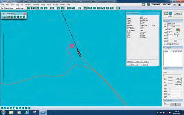
The AIS-SART is detected only by AIS vessels within range. The transmitted information can be displayed on a chart plotter or Electronic Chart Display and Information System (ECDIS) if they are interfaced with an AIS receiver. AIS equipment receiving the AIS-SART signal are able to display the range and bearing to the AIS-SART. Vessel’s AIS systems will recognise the 970 prefix as a SART, and display the target as a circle containing a cross with solid lines (IMO agreed symbol). The ECDIS software will display the symbol in red, see image on the previous page.
AIS-MOB (Man Overboard)
A small portable AIS-SART (Personal Locator Beacon - PLB) with a built-in GPS (See paragraph AIS-SART above) which transmits an emergency AIS-SART sentence (MOB and position) which triggers an alarm on all AIS enabled chart plotters / PC’s within range (typically four miles). Upon activation, all nearby vessels equipped with AIS receivers, will be notified with messages appearing on their AIS device and connected ECDIS systems. Updated in real time, the GPS provides an accurate position of the AIS-SART.
REVISION QUESTIONS
111 } What is the IMO symbol for an AIS-SART?
1 112 } What vessels detect an AIS-SART?
1 113 } What is an AIS-MOB?
SeArCH AN d reSCUe TrANSPoNderS
general
A Search and rescue Transponder, or SArT, is a battery-powered portable device, which may be used by a survival craft to indicate its position to searching aircraft and vessels.
The SArT operates in the 9.3 to 9.5 GHz band and will respond only to radar equipment operating on those frequencies (X Band, 3 Centimetre radar). The SArT will not respond to 3 GHz (S band, 10 Centimetre) radar. The SArT should operate in the standby mode for a minimum of 96 hours with a further eight hours of transmission once activated.
PoSItIonIng oF tHe Sart
Under no circumstances should the SArT be placed in the water. The SArT should be mounted at least one metre above the water line. when in the survival craft, survivors should position the SArT as high as possible with the aid of an oar or the lifeboat mast. Some manufacturers will supply the SArT with a short telescopic type mast of approximately one metre in length.
Sart oPeratIon
once switched on, the SArT will scan the X band of radar frequencies. when a searching radar is detected, the SArT will lock onto that particular radar frequency and commence to transmit on the entire X band, thus enabling all vessels in the vicinity to receive an indication of the SArT transmission.
on detecting signals from distant radar equipment, an activated SArT will generate a series of response signals of twelve blips which will be displayed on the receiving radar screen, extending in a line, 8 nautical miles in length, outward from the SArT position, along its line of bearing. This unique radar signal is easily recognised and the rescue vessel or aircraft can locate the survivors. (See Fig. 5 and 6)
An interrogated SArT will provide proof to survivors that it is operating, by means of an audible and/or visible flashing light.
28
MARINE VHF RADIO OPERATORS HANDBOOK
locatIon dIStanceS
A SArT should respond to a ship’s radar with a scanner height of 15 metres at a distance of at least 5 nautical miles. once locked on to a searching radar there will be a slight delay in the changeover from the SArT’s standby or receive mode to transmit mode. This slight delay may cause a small position error of up to 150 metres on the radar screen of the blip associated with the position of the SArT. Subsequent radar sweeps will confirm the actual location of the SArT.
reVISIoN QUeSTIoNS
114 }
1 115 }
what is the general description of a SArT?
what type of marine radar is capable of detecting an activated SArT?
119 } How should the SArT be positioned for survival operations?
116 }
once activated for how long should the SArT be capable of transmitting?
117 }
when switched to the standby mode, what band of frequencies will the SArT scan?
118 }
when switched of to the standby mode, for how long should the SArT be capable of operating?
12 20 } what is the recommended height for positioning the SArT?
12 21 } How is a SArT transmission identified?
1 122 } How many miles does the SArT signal extend to?
1 123 } How would a survivor be alerted to the fact that the SArT has been interrogated?
Power SUPPLIeS
MaIntenance Free BatterIeS
Maintenance free lead-acid or gel type batteries are becoming increasingly more popular and available to mariners. Users of these types of batteries are recommended to follow the manufacturer’s guidelines in ascertaining the condition of the battery regarding replacement. on vessels where it is mandatory to carry an independent emergency means of electrical supply, for communications equipment, it may also be a requirement to replace maintenance free batteries after a short operational period of 1 year.
Vessel altered course towards the SART 24 MIle range
Heading line Vessel heading due North 24 MIle
Fig. 6 - Image on the radar once the vessel has altered course to head towards the Sart position
range
AUSTRALIAN MARITIME COLLEGE 29
Fig. 5 - Sart indication as seen on a marine radar on a bearing of 045°t. (radar display set to north up)
lead acId BatterIeS
Many marine batteries used on boats are still of the lead-acid variety. Lead-acid cells consist of a combination of lead and lead peroxide plates. These plates are kept in a solution of sulphuric acid and water (the electrolyte) which produces a potential difference between the plates, and current can flow when a load, such as a marine radio, is connected. during this ‘discharge’ cycle, the sulphuric acid or the material in the plates is used up. The potential difference no longer exists and current can no longer flow. This process is reversed by passing a current through the cell in the opposite direction and this is known as ‘charging’.
Battery conStructIon (courtesy of Battery council International)
Batteries are made of five basic components:
A resilient Plastic container.
Positive and negative internal plates made of lead.
Plate separators made of porous synthetic material. electrolyte, a dilute solution of sulfuric acid and water, better known as battery acid.
Lead terminals, the connection point between the battery and whatever it powers.
cell Voltage
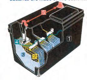
each lead-acid cell has a nominal voltage of 2 volts. A physically larger cell does not supply a higher voltage (Volts). Cells in a battery are combined to give a total battery voltage, i.e. three cells to produce a 6 volt battery, or six cells to produce a 12 volt battery. each cell will have a filler cap to enable topping up of the electrolyte by distilled or demineralised water. Three filler caps indicate a 6 volt battery.
cell caPacIty
electrical current is measured in amperes (amps). each lead-acid battery has the capacity to supply an amount of current over a specific time and this is known as its Ampere Hour Capacity (AHC). A large cell has the ability to provide a higher AHC over a short period of time or a low current over a longer period of time. Manufacturers will specify the AHC of an individual battery type.
Battery connectIon
Batteries can be connected to each other, in order to provide a total operating voltage.
30
Fig. 8Series connection PoSItIVe negatIVe
Fig. 9Parallel connection PoSItIVe negatIVe
1 2 3 4 5 1 2 3 4 5
MARINE VHF RADIO OPERATORS HANDBOOK
Fig. 7 - Battery construction
SerIeS connections where the negative terminal of one battery is connected to the positive terminal of another battery. i.e. two 6 volt batteries of equal AHC connected together in order to produce a 12 volt operating voltage with an AHC of each battery.
Parallel connections, whereby all the positive terminals, of a bank of batteries, are connected together, and all the negative terminals are connected together. In the following Figure two 6 volt batteries with equal AHC connected together in parallel will produce a total of 6 volts with an AHC of the sum of the AHC of each battery, therefore following a longer period overall for the current to flow.
Battery HazardS
There are two hazards associated with lead-acid batteries that ship station operators should be aware of:
•the risk of explosion; and
•the risk of chemical burns.
As a result of the chemical process occurring within the cells of a battery during charging, Hydrogen gas is produced. when mixed with air, this can form a highly explosive mixture which can be ignited by a naked flame, a lighted cigarette, or a spark.
The spark caused by making or breaking an electrical connection in the vicinity of the charging battery may be sufficient to ignite the hydrogen-air mixture. Batteries should be located as close to the radio equipment as possible, and placed in a well-ventilated container or locker. If using metal tools to work on battery connections, extreme care must be taken to ensure that terminals are not short-circuited.
The electrolyte in battery cells consists of a mixture of water and Sulphuric acid. It is sufficiently concentrated, particularly after charging, to damage eyes, skin or clothes if spilt or splashed. Immediate and prolonged application of
eSSentIal Battery MaIntenance
The functioning of radio equipment is dependent on power supplied by the battery. If it is to provide adequate performance in the event of an emergency, regular and careful maintenance is required.
A battery’s service life also depends on the manner in which it is treated. To ensure the best performance from a battery it is important that a battery:
•is kept clean, dry and free from terminal corrosion;
•has the electrolyte kept at the correct level; and
•is kept correctly charged.
Battery cleanlIneSS
A battery top should be kept clean. A dirty battery top may hold spilt electrolyte on its surface, thereby providing a path for the electrical current to leak away. It is important to keep the outside surfaces of a battery dry and free of contamination.
Corrosion forming on terminal clamps may seriously affect, or even prevent, the ability of the battery to supply current. Corrosion will be evident by the formation of a white-green powder between the battery terminals and the terminal clamps. In this situation, the terminal clamp should be removed and both it and the terminal post cleaned.
To minimise the likelihood of corrosion, terminal posts and clamps should be lightly smeared with Vaseline™ or petroleum jelly.
A battery which is nearly flat, is defective or has corrosion of on its terminals may be able to provide sufficient current to operate the receiver, but not the transmitter. Should the transmitter fail to operate and the dial lights or channel display lights dim significantly when the transmit button is operated, the battery should be suspected.
electrolyte leVel
The level of electrolyte inside a battery is important. As a result of the chemical action inside a battery, water is lost. This should be replaced with distilled or demineralised water.
AUSTRALIAN MARITIME COLLEGE 31
Seawater must not be used under any circumstances. The level of the electrolyte should be maintained at approximately 10 mm above the plates unless otherwise specified by the manufacturer. If the electrolyte level is too high, it may overflow during charging providing an unwanted discharge path. If the electrolyte is too low, the plates are exposed to the air and permanent damage and loss of capacity may result.
It may be noticed that a battery that is nearing the end of its useful life will require more frequent topping-up than has been previously necessary. Low-maintenance batteries will require infrequent topping-up. Maintenance-free batteries may require none at all.
correct cHargIng
To provide the best service, a battery must be correctly charged. Both overcharging and undercharging can seriously affect its performance.
on small vessels, the usual means of charging the radio battery will be an alternator or generator attached to the vessel’s engine. An associated regulator, which reduces the charging current as necessary, should prevent overcharging.
Vessels that are used frequently (say, several times each week) should have no problem maintaining a fully charged radio battery. However, on vessels that are used relatively infrequently (say, once every few weeks), it is likely that, during storage, even a battery that starts as fully charged will self-discharge and go flat.
For safety reasons, it is important that a small boat owner is able to determine the general condition of a battery and its ability to supply current over a period of time (its capacity). An indication of the level of charge in a battery may be obtained by either:
•measuring the specific gravity of the electrolyte; or
•measuring the on-load terminal voltage.
MeaSurIng tHe SPecIFIc graVIty
The specific gravity, also called the relative density, of the electrolyte (the liquid inside the battery) varies proportionally with the amount of charge in the battery. It is highest when the battery is fully charged and lowest when the battery is fully discharged or flat. It follows that the amount of charge in a battery can be determined by measuring the specific gravity of the electrolyte.
A simple, inexpensive device called a hydrometer is used to measure specific gravity.
In general, for a fully charged battery, the specific gravity should measure about 1.250. Half charge will be indicated by a reading of 1.200 and fully discharged by 1.150. All cells in a battery should indicate a similar specific gravity.
A variation of more than about 0.025 will indicate a faulty cell and the battery should be replaced.
Specific gravity readings should not be taken immediately after topping-up a cell as the added water will float towards the top of the cell and give a false reading. Charging for thirty minutes or more after topping-up will mix the electrolyte and allow accurate readings. Top up the battery before charging as the pouring of cold distilled water onto hot acid in the battery will cause splatter. Batteries which have cells where specific gravity readings fail to rise, or respond poorly to adequate charging, should be replaced.

32
1.3 1.2 1.1 R E C H A R G E F A I R G O O D rubber Bulb Hollow glass float Glass Barrel Scale electrolyte being measured weight to hold float erect rubber hose 1.150 1.200 1.250 1.300
Fig. 10 Hydrometer
MARINE VHF RADIO OPERATORS HANDBOOK
MEASURING THE ON-LOAD TERMINAL VOLTAGE
Measurement of the terminal voltage when a battery is supplying current to a load, such as a transmitting radio, will also provide an indication of the amount of charge in a battery. This measurement is known as the on-load terminal voltage.
For a 12 volt battery, the on-load terminal voltage should not fall below approximately 11.4 volts while transmitting. If the voltage does fall significantly below this figure, the battery requires charging. If after charging, the on-load terminal voltage still falls significantly below 11.4 volts, it is an indication of a faulty cell and the battery should be replaced. Measurement of the off-load (when the battery is idle) terminal voltage of a battery is a poor indication of its condition.
loSS oF caPacIty
A battery will suffer a gradual loss of capacity during its life. This is inevitable and the battery should be replaced when the capacity loss becomes significant. Many lead-acid batteries have a commercial life of only two to three years. However, the useful life of a battery can be considerably shortened by:
• operating a battery in a low state of charge for long periods;
• allowing a battery to stand in a discharged state for long periods;
• leaving a charged battery for long periods without periodic charging; and •overcharging.
connectIon oF BatterIeS durIng eMergencIeS
For a vessel with more than a single bank of batteries, it is highly recommended to connect the batteries in parallel during emergency situations. The battery on/off or interchange switch will indicate if this is possible.
reVISIoN QUeSTIoNS
what is the most common type of battery available for marine use?
what is the nominal voltage per cell, of a lead acid battery?
what is a battery's ability to produce current known as?
what is the total voltage of two 6 volt batteries connected in series?
what is the total voltage of two 6 volt batteries connected in parallel?
what is the total voltage of two 12 volt batteries connected in series?
what is the total voltage of two 12 volt batteries connected in parallel?
what is the total AHC for two batteries connected in series?
what is the total AHC for two batteries connected in parallel?
what type of gas is produced by a lead acid battery during the charging process?
1 134} what is the liquid in a battery known as?
1 135 } what is the liquid, in a lead acid battery, a mixture of?
1 136 } what type of acid is contained in the liquid of a lead acid battery?
1 137 } At what level should the liquid in the lead acid battery be maintained?
1 138 } what should the electrolyte be topped up with?
1 139 } How is corrosion on a lead acid battery terminal minimised?
1 140 } describe the basic maintenance of a battery?
1 141 } what is the basic method of determining the operating condition of the lead acid battery?
1 142 } what instrument is used to determine the condition of a lead acid battery?
1 143 } what is the specific gravity per cell of a well maintained lead acid battery?
1 144 } How is it recommended to connect two banks of batteries in the event of an emergency?
} 1 125 } 1 126 } 1 127 } 1 128 } 1 129 } 1 130 } 1 131 } 1 132 } 1 133 }
124
AUSTRALIAN MARITIME COLLEGE 33
SUGG e STed F or MAT F or A rAdIo L o GBoo K PAG e
name of Vessel:
any other identity: MMSI:
date and Time Station/MMSI fromStation/MMSI todetails of Calls, Signals & distress workingFrequency/Channel
34
MARINE VHF RADIO OPERATORS HANDBOOK
TABLe oF TrANSMITTING C HANNeLS IN THe
V HF MArITIMe MoBILe BANd
extracted from Appendix 18 (Rev. WRC -15) to the ITU radio regulations
(See Article 52)
NOTE A – For assistance in understanding the Table, see Notes a) to zz) below. (WRC-15)
NOTE B – The Table below defines the channel numbering for maritime VHF communications based on 25 kHz channel spacing and use of several duplex channels. The channel numbering and the conversion of twofrequency channels for single-frequency operation shall be in accordance with Recommendation ITU-R M.1084-5 Annex 4, Tables 1 and 3. The Table below also describes the harmonized channels where the digital technologies defined in the most recent version of Recommendation ITU-R M.1842 could be deployed. (WRC-15)
35 M ISCeLLANeoUS
AUSTRALIAN MARITIME COLLEGE
channel notes* F Frequency Use From Coast (MHz) 01 156.050160.650 02 m) 156.100160.700 03 m) 156.150160.750 04 m) 156.200 160.800 05 m) 156.250160.850 06 f) 156.300 m) 07 156.350160.950 08 156.400 09 i) 156.450156.450 10 h), q) 156.500156.500 11 156.550156.550 12 156.600156.600 13 k) 156.650156.650 14 156.700 m) q) 156.70 15 g) 156.750156.750 16 156.800156.800 17 g) 156.850156.850 f) 18 m) 156.900161.500 20 157.000 161.600 m) 21 157.050161.650 22 157.100 161.700 y), wa) y), wa) 23 157.150161.750 x), y), wa) 60 m) 156.025160.625 61 m) 156.075160.675 62 m) 156.125160.725 From Ships (MHz) Public Correspondence Public Correspondence Public Correspondence Public Correspondence Public Correspondence Public Correspondence Search and Rescue Port Operations and Commercial Operations DUPLEX DUPLEX DUPLEX DUPLEX DUPLEX SIMPLEX DUPLEX SIMPLEX SIMPLEX SIMPLEX SIMPLEX SIMPLEX SIMPLEX SIMPLEX SIMPLEX SIMPLEX SIMPLEX Port Operations Port Operations Port Operations Port Operations Port Operations, Distress, Urgency and Safety Port Operations Commercial Operations Distress, Safety and Calling Commercial Operations Port Operations Port Operations DUPLEX DUPLEX DUPLEX DUPLEX DUPLEX DUPLEX Repeater (distress, urgency, safety and ship movement) Public Correspondence Public Correspondence Public Correspondence Public Correspondence Repeater (distress, urgency, safety and ship movement) 156.400 DUPLEX DUPLEX 156.300
use in relation to Radiotelephony, Digital
Channels 24, 84, 25 and 85 may be merged in order to form a unique duplex channel with a bandwidth of 100 kHz in order to operate the VDES terrestrial component described in the most recent version of Recommendation ITU-R M.2092 (WRC-15) of the ITU.
36 MARINE VHF RADIO OPERATORS HANDBOOK 70 f), j) 156.525156.525 71156.575156.575 72 l) 156.625 73 h), i) 156.675156.675 74 156.725156.725 63 m) 156.175160 775 64 m) 156.225160 825 Public Correspondence Port Operations Digital Selective Callsign - Distress, Safety and Calling Professional Fishing Port Operations, Commercial and Non-Commercial Operations and Professional Fishing 65 156.275 160 875 66 156.325 160 925 Public Correspondence m) m) 67 156.375 156.375 68 156.425 156.425 Port Operations DUPLEX DUPLEX DUPLEX DUPLEX SIMPLEX SIMPLEX SIMPLEX SIMPLEX SIMPLEX Commercial Operations Non-commercial Operations Port Operations Supplementary to Ch16 (for Distress, Urgency and Safety) h) SIMPLEX SIMPLEX 78 156.925 161.525 m) 2006 79 156.975 161.575 80 157.025 161.625 81 157.075 161.675 82 157.125 161.725 83 157.175 161.775 24* 84* 25* 85* 87 157.375 157.375 88157.425 157.425 AIS 1 AIS 2 160.900 1019 2019 156.950 156.950 m) y), wa) y), wa) x), y), wa) w), y), wa) 1026 2026 w), ww), x) 157.300 1086 w), ww), x) 157.325 2086 1027 157.350 z), zz) ASM1 (2027) z), zz) 1028 z), zz) ASM2 (2028) z), zz) 157.400 76 156.825 77156.875 156.825 75 n), s) 156.775156.775 157.200161.800 157.250161.850 157.225161.825 157.275161.875 161.975161.975 162.025162.025 161.950161.950 Automatic Identification System Satellite Port Operations DUPLEX DUPLEX DUPLEX SIMPLEX SIMPLEX SIMPLEX SIMPLEX SIMPLEX SIMPLEX SIMPLEX Port Operations Port Operations Port Operations Port Operations DUPLEX DUPLEX DUPLEX 162.000162.000 Application Specific Messaging Automatic Identification System Satellite Professional Fishing, Non-commercial Operations SIMPLEX SIMPLEX SIMPLEX Commercial Operations n), s) Repeater
and Public Correspondence Repeater
Repeater (distress,
Public Correspondence VHF Data Exchange System Port Operations Experimental
Selective
Identification System Port Operations 156.875 VHF Data Exchange System Automatic Identification System VHF Data Exchange System VHF Data Exchange System VHF Data Exchange System VHF Data Exchange System VHF Data Exchange System VHF Data Exchange System DUPLEX DUPLEX SIMPLEX SIMPLEX SIMPLEX DUPLEX SIMPLEX SIMPLEX SIMPLEX SIMPLEX r) Application Specific Messaging 160.900 157.300 157.350 157.400 161.550 161.900 161.925 161.550 161.900 161.925 DUPLEX Automatic Identification System channel notes* F Frequency Use From Coast (MHz) From Ships (MHz)
(distress, urgency, safety and ship movement)
(distress, urgency, safety and ship movement)
urgency, safety and ship movement)
Calling and Automatic
156.625 157.325 SIMPLEX
General notes
a) Administrations may designate frequencies in the inter-ship, port operations and ship movement services for use by light aircraft and helicopters to communicate with ships or participating coast stations in predominantly maritime support operations under the conditions specified in Nos. 51.69, 51.73, 51.74, 51.75, 51.76, 51.77 and 51.78 However, the use of the channels which are shared with public correspondence shall be subject to prior agreement between interested and affected administrations.
b) The channels of the present Appendix, with the exception of channels 06, 13, 15, 16, 17, 70, 75 and 76, may also be used for high-speed data and facsimile transmissions, subject to special arrangement between interested and affected administrations.
c) The channels of the present Appendix, with the exception of channels 06, 13, 15, 16, 17, 70, 75 and 76, may be used for direct-printing telegraphy and data transmission, subject to special arrangement between interested and affected administrations. (WRC-12)
d) The frequencies in this table may also be used for radiocommunications on inland waterways in accordance with the conditions specified in No. 5.226
e) Administrations may apply 12.5 kHz channel interleaving on a non-interference basis to 25 kHz channels, in accordance with the most recent version of Recommendation ITU-R M.1084, provided:
– it shall not affect the 25 kHz channels of the present Appendix maritime mobile distress and safety, automatic identification system (AIS), and data exchange frequencies, especially the channels 06, 13, 15, 16, 17, 70, AIS 1 and AIS 2, nor the technical characteristics set forth in Recommendation ITU-R M.489-2 for those channels;
– implementation of 12.5 kHz channel interleaving and consequential national requirements shall be subject to coordination with affected administrations. (WRC-12)
Specific notes
f) The frequencies 156.300 MHz (channel 06), 156.525 MHz (channel 70), 156.800 MHz (channel 16), 161.975 MHz (AIS 1) and 162.025 MHz (AIS 2) may also be used by aircraft stations for the purpose of search and rescue operations and other safety-related communication. (WRC-07)
g) Channels 15 and 17 may also be used for on-board communications provided the effective radiated power does not exceed 1 W, and subject to the national regulations of the administration concerned when these channels are used in its territorial waters.
h) Within the European Maritime Area and in Canada, these frequencies (channels 10, 67, 73) may also be used, if so required, by the individual administrations concerned, for communication between ship stations, aircraft stations and participating land stations engaged in coordinated search and rescue and anti-pollution operations in local areas, under the conditions specified in Nos. 51.69, 51.73, 51.74, 51.75, 51.76, 51.77 and 51.78.
i) The preferred first three frequencies for the purpose indicated in Note a) are 156.450 MHz (channel 09), 156.625 MHz (channel 72) and 156.675 MHz (channel 73).
j) Channel 70 is to be used exclusively for digital selective calling for distress, safety and calling.
k) Channel 13 is designated for use on a worldwide basis as a navigation safety communication channel, primarily for intership navigation safety communications. It may also be used for the ship movement and port operations service subject to the national regulations of the administrations concerned.
l) These channels (AIS 1 and AIS 2) are used for an automatic identification system (AIS) capable of providing worldwide operation, unless other frequencies are designated on a regional basis for this purpose. Such use should be in accordance with the most recent version of Recommendation ITU-R M.1371. (WRC-07)
Notes
referring to the Table
AUSTRALIAN MARITIME COLLEGE 37
m) These channels may be operated as single frequency channels, subject to coordination with affected administrations. The following conditions apply for single frequency usage:
– The lower frequency portion of these channels may be operated as single frequency channels by ship and coast stations.
– Transmission using the upper frequency portion of these channels is limited to coast stations.
– If permitted by administrations and specified by national regulations, the upper frequency portion of these channels may be used by ship stations for transmission. All precautions should be taken to avoid harmful interference to channels AIS 1, AIS 2, 2027* and 2028*. (WRC-15)
*From 1 January 2019, channel 2027 will be designated ASM 1 and channel 2028 will be designated ASM 2.
mm) Transmission on these channels is limited to coast stations. If permitted by administrations and specified by national regulations, these channels may be used by ship stations for transmission. All precautions should be taken to avoid harmful interference to channels AIS 1, AIS 2, 2027* and 2028*. (WRC-15)
*From 1 January 2019, channel 2027 will be designated ASM 1 and channel 2028 will be designated ASM 2.
n) With the exception of AIS, the use of these channels (75 and 76) should be restricted to navigation-related communications only and all precautions should be taken to avoid harmful interference to channel 16, by limiting the output power to 1 W. (WRC-12)
o) (SUP - WRC-12)
p) Additionally, AIS 1 and AIS 2 may be used by the mobile-satellite service (Earth-to-space) for the reception of AIS transmissions from ships. (WRC-07)
q) When using these channels (10 and 11), all precautions should be taken to avoid harmful interference to channel 70. (WRC-07)
r) In the maritime mobile service, this frequency is reserved for experimental use for future applications or systems (e.g. new AIS applications, man over board systems, etc.). If authorized by administrations for experimental use, the operation shall not cause harmful interference to, or claim protection from, stations operating in the fixed and mobile services. (WRC-12)
s) Channels 75 and 76 are also allocated to the mobile-satellite service (Earth-to-space) for the reception of long-range AIS broadcast messages from ships (Message 27; see the most recent version of Recommendation ITU-R M.1371). (WRC-12)
t) (SUP - WRC-15)
u) (SUP - WRC-15)
v) (SUP - WRC-15)
w) In Regions 1 and 3:
Until 1 January 2017, the frequency bands 157.200-157.325 MHz and 161.800-161.925 MHz (corresponding to channels: 24, 84, 25, 85, 26 and 86) may be used for digitally modulated emissions, subject to coordination with affected administrations. Stations using these channels or frequency bands for digitally modulated emissions shall not cause harmful interference to, or claim protection from, other stations operating in accordance with Article 5 5.
From 1 January 2017, the frequency bands 157.200-157.325 MHz and 161.800-161.925 MHz (corresponding to channels: 24, 84, 25, 85, 26 and 86) are identified for the utilization of the VHF Data Exchange System (VDES) described in the most recent version of Recommendation ITU-R M.2092. These frequency bands may also be used for analogue modulation described in the most recent version of Recommendation ITU-R M.1084 by an administration that wishes to do so, subject to not causing harmful interference to, or claiming protection from other stations in the maritime mobile service using digitally modulated emissions and subject to coordination with affected administrations. (WRC-15)
38 MARINE VHF RADIO OPERATORS HANDBOOK
wa)
In Regions 1 and 3:
Until 1 January 2017, the frequency bands
157.025-157.175 MHz and 161.625-161.775 MHz (corresponding to channels: 80, 21, 81, 22, 82, 23 and 83) may be used for digitally modulated emissions, subject to coordination with affected administrations. Stations using these channels or frequency bands for digitally modulated emissions shall not cause harmful interference to, or claim protection from, other stations operating in accordance with Article 5
From 1 January 2017, the frequency bands
157.025-157.100 MHz and 161.625-161.700 MHz (corresponding to channels: 80, 21, 81 and 22) are identified for utilization of the digital systems described in the most recent version of Recommendation ITU-R M.1842 using multiple 25 kHz contiguous channels.
From 1 January 2017, the frequency bands
157.150-157.175 MHz and 161.750-161.775 MHz (corresponding to channels: 23 and 83) are identified for utilization of the digital systems described in the most recent version of Recommendation ITU-R M.1842 using two 25 kHz contiguous channels. From 1 January 2017, the frequencies 157.125 MHz and 161.725 MHz (corresponding to channel: 82) are identified for the utilization of the digital systems described in the most recent version of Recommendation ITU-R M.1842.
The frequency bands
157.025-157.175 MHz and 161.625-161.775 MHz (corresponding to channels: 80, 21, 81, 22, 82, 23 and 83) can also be used for analogue modulation described in the most recent version of Recommendation ITU-R M.1084 by an administration that wishes to do so, subject to not claiming protection from other stations in the maritime mobile service using digitally modulated emissions and subject to coordination with affected administrations. (WRC-15)
ww) In Region 2, the frequency bands 157.200-157.325 and 161.800-161.925 MHz (corresponding to channels: 24, 84, 25, 85, 26 and 86) are designated for digitally modulated emissions in accordance with the most recent version of Recommendation ITU-R M.1842.
In Canada and Barbados, from 1 January 2019 the frequency bands 157.200-157.275 and 161.800161.875 MHz (corresponding to channels: 24, 84, 25 and 85) may be used for digitally modulated emissions, such as those described in the most recent version of Recommendation ITU-R M.2092, subject to coordination with affected administrations. (WRC-15)
x) From 1 January 2017, in Angola, Botswana, Lesotho, Madagascar, Malawi, Mauritius, Mozambique, Namibia, Democratic Republic of the Congo, Seychelles, South Africa, Swaziland, Tanzania, Zambia and Zimbabwe, the frequency bands 157.125-157.325 and 161.725-161.925 MHz (corresponding to channels: 82, 23, 83, 24, 84, 25, 85, 26 and 86) are designated for digitally modulated emissions.
From 1 January 2017, in China, the frequency bands 157.150-157.325 and 161.750-161.925 MHz (corresponding to channels: 23, 83, 24, 84, 25, 85, 26 and 86) are designated for digitally modulated emissions. (WRC-12)
xx) From 1 January 2019, the channels 24, 84, 25 and 85 may be merged in order to form a unique duplex channel with a bandwidth of 100 kHz in order to operate the VDES terrestrial component described in the most recent version of Recommendation ITU-R M.2092. (WRC-15)
y) These channels may be operated as single or duplex frequency channels, subject to coordination with affected administrations. (WRC-12)
z) Until 1 January 2019, these channels may be used for possible testing of future AIS applications without causing harmful interference to, or claiming protection from, existing applications and stations operating in the fixed and mobile services.
From 1 January 2019, these channels are each split into two simplex channels. The channels 2027 and 2028 designated as ASM 1 and ASM 2 are used for application specific messages (ASM) as described in the most recent version of Recommendation ITU-R M.2092. (WRC-15)
AUSTRALIAN MARITIME COLLEGE 39
zx) In the United States, these channels are used for communication between ship stations and coast stations for the purpose of public correspondence. (WRC-15)
zz) From 1 January 2019, channels 1027, 1028, 87 and 88 are used as single-frequency analogue channels for port operation and ship movement. (WRC-15)
MArINe VHF CHANNeLS For USe BY SHIP STATIoNS
40 MARINE VHF RADIO OPERATORS HANDBOOK
Purpose Carrier Frequency (Tx/rx) & Channel No. 156.575 MHz (Ch 71) Communicating with Limited coast and ship stations Calling and working 156.625 MHz (Ch 72) Ship Stations Calling and working 156.875 MHz (Ch 77) Ship Stations Calling and working
Carrier Frequency (Tx/rx) & Channel No. Communicating with Purpose 156.300 MHz (Ch 6) Ship Stations Calling and working 156.400 MHz (Ch 8) Ship Stations Calling and working 156.625 MHz (Ch 72) Ship Stations Calling and working 156.725 MHz (Ch 74) Limited coast stations and ship stationsCalling and working 156.925/161.525 MHz (Ch 78)Limited coast stations Calling and working
taBle 2. coMMercIal VeSSel FreQuencIeS
Carrier Frequency (Tx/rx) & Channel No. Communicating with Purpose 156.625 MHz (Ch 72) Ship stations Calling and working 156.675 MHz (Ch 73) Limited coast and ship stations Calling and working 156.875 MHz (Ch 77) Ship stations Calling and working
taBle 3. yacHtS and PleaSure VeSSelS FreQuencIeS
1.
taBle
ProFeSSIonal FISHIng VeSSelS FreQuencIeS
taBle 4. Port oPeratIonS FreQuencIeS
taBle 5. VHF MarIne rePeater cHannelS
note. PuBlIc correSPondence cHannelS
Ship stations may use those VHF frequencies detailed by their provider for public correspondence.
Subject to the International radio regulations, when operating outside Australian territorial waters, ship stations may use any maritime mobile frequency authorised by those regulations. details may be found in the Manual for Use by the Maritime Mobile and Maritime Mobile-Satellite Service, published by the International Telecommunication Union.
AUSTRALIAN MARITIME COLLEGE 41
Carrier Frequency (Tx/rx) & Channel No. Communicating with Purpose 156.300 MHz (Ch 6) Ship stations Calling and working 156.400 MHz (Ch 8) Ship stations Calling and working 156.425 MHz (Ch 68) Limited coast stations Calling and working 156.450 MHz (Ch 9) Limited coast stations and ship stationsCalling and working 156.500 MHz (Ch 10) Limited coast stations and ship stationsCalling and working 156.550 MHz (Ch 11) Limited coast stations Calling and working 156.600 MHz (Ch 12) Limited coast stations Calling and working 156.625 MHz (Ch 72) Ship stations Calling and working 156.650 MHz (Ch 13) Limited coast stations and ship stationsCalling and working 156.700 MHz (Ch 14) Limited coast stations Calling and working 156.975/161.575 MHz (Ch 79)Limited coast stations Calling and working 157.000/161.600 MHz (Ch 20)Limited coast stations Calling and working
Carrier Frequency (Tx/rx) & Channel No. 157.050/161.650 MHz (Ch 21) Communicating with Limited coast and ship stations via repeaters Purpose Vessel movements, safety of vessels and persons 157.100/161.700 MHz (Ch 22)Limited coast and ship stations via repeatersVessel movements, safety of vessels and persons 157.025/161.625 MHz (Ch 80)Limited coast and ship stations via repeatersVessel movements, safety of vessels and persons 157.075/161.675 MHz (Ch 81)Limited coast and ship stations via repeatersVessel movements, safety of vessels and persons 157.125/161.725 MHz (Ch 82)Limited coast and ship stations via repeaters Vessel movements, safety of vessels and persons
157 375 MHz (Ch 87) Limited coast stations Calling and working 157.425 MHz (Ch 88) Limited coast stations Calling and working
PHoNeTIC ALPHABeT ANd FIGUre Code
when spelling is necessary, only the following spelling table should be used:
Letter to be transmitted
A
Code word to be used
Spoken as *
Alfa al FAH
B Bravo BraH VoH
C Charlie cHar Lee or SHAr Lee
d delta dell TAH
e echo eck oH
F Foxtrot FokS TroT
G Golf GoLF
H Hotel HoH tell
I India In dee AH
j juliett jew Lee ett
K Kilo key LoH
L Lima lee MAH
M Mike MIKe
N November No VeM Ber
o oscar oSS CAH
P Papa PAH PaH
Q Quebec KeH Beck
r romeo row Me oH
S Sierra See aIr rAH
T Tango tan Go
U Uniform you nee ForM or oo nee ForM
V Victor VIk TAH
w whiskey wISS KeY
X X-ray eckS rAY
Y Yankee yang KeY
Z Zulu zoo Loo
*The syllables to be emphasised are underlined.
42
MARINE VHF RADIO OPERATORS HANDBOOK
** each syllable should be equally emphasised.
FIgure code
A few digits and numbers have a modified pronunciation compared to general english:
** each syllable should be equally emphasised.
AUSTRALIAN MARITIME COLLEGE 43
Spoken as ** Letter to be transmitted oVer Code word to be used Invitation to reply oVer oUT This transmission is ended oUT deCIMAL PoINT decimal dAY-See-MAL FULL SToP Stop SToP CoMMA Comma CoMMA / oblique Stroke oBLIQUe
MIScellaneouS
Letter to be transmitted Code word to be used Spoken as ** 0 zero ZeeroH 1 one wUN 2 two Too 3 three Tree 4 four Fower 5 five FIFe 6 six SeKS 7 seven SeVeN 8 eight AIT 9 nine NINer 10 one zero wUNZeeroH 1000 thousand ToUSANd
Transmission and reception taking place on a single frequency dUPLeX Simultaneous transmission and reception taking place on separate but paired frequencies
deFInItIon SIMPLeX
STANdArd MArINe CoMMUNICATIoN PHrASeS
english is the language most widely used at sea. To facilitate radiotelephony communications, the International Maritime organisation has compiled a vocabulary of frequently used words and phrases in a book entitled IMo Standard Marine Communication Phrases (SMCP) 2002. The complete SMCP is also available at the IMo website at: http://www.imo.org
In the interests of accuracy, brevity and clarity it is sound practice for operators to use the standard vocabulary when possible.
A selection of the standard vocabulary is contained in the following paragraphs.
MeSSage MarkerS
If necessary, messages passed by radiotelephony may be preceded by the following message markers: “Instruction” Indicates that the following message implies the intention of the sender to influence the recipient(s) by a “advice” regulation. Indicates that the following message implies the intention of the sender to influence the recipient(s) by a recommendation.
“warning” Indicates that the following message informs other traffic participants about dangers. “Information” Indicates that the following message is restricted to observed facts.
“Question”
“answer”
Indicates the following message is of interrogative character. Indicates that the following message is the reply to a previous question. “request” Indicates that the content of the following message is asking for action with respect to the ship.
“Intention” Indicates that the following message informs others about immediate navigational actions intended to be taken.
reSPonSeS
where the answer to a question is in the affirmative, say: “Yes” followed by the appropriate phrase in full. where the answer to a question is in the negative, say: “No” followed by the appropriate phrase in full. where the information is not immediately available, but soon will be, say: “Stand by”. where the information cannot be obtained, say: “No information”. where a message is not properly heard, say: “Say again”. where a message is not understood, say: “Message not understood”.
MIScellaneouS PHraSeS
what is your name (and any other identity)?
How do you read me ?
I read you. . .
Bad/one
Poor/two
Fair/three
Good/four with signal strength one (i.e. barely perceptible) with signal strength two (i.e. weak) with signal strength three (i.e. fairly good) with signal strength four (i.e. good)
excellent/five with signal strength five (i.e. very good)
44
MARINE VHF RADIO OPERATORS HANDBOOK
Stand by on VHF channel.... change to channel....
I cannot read you (pass your message through..../Advise try channel....)
I cannot understand you. Please use the Standard Marine Vocabulary/International Code of Signals. corrections when a mistake is made in a message, say: “Mistake….” followed by the word: “Correction…” plus the corrected part of the message.
Example: “My present speed is 14 knots – mistake.
Correction, my present speed is 12 knots, one-two knots” readiness
Go ahead, I am ready/not ready to receive your message
I do not have channel.... Please use channel.... repetition
If any parts of the message are considered sufficiently important to need particular emphasis, use the word “repeat”, e.g. “do not repeat do not overtake”.
acknowledgement
Acknowledgement of a message should be by the word “received”.
Position
when latitude and longitude are used, these should be expressed in degrees and minutes (and decimals of a minute, if necessary), north or south of the equator and east or west of Greenwich. when the position is related to a mark, the mark shall be a well-defined charted object. The bearing shall be in the 360-degree notation from true north and shall be that of the position from the mark.
courses
Courses should always be expressed in the 360-degree notation from true north (unless otherwise stated). whether this is to, or from, a mark can be stated.
Bearings
The bearing of the mark or vessel concerned is the bearing in the 360-degree notation from true north (unless otherwise stated), except in the case of relative bearings. Bearings may be either from the mark or from the vessel.
distances
distances should be expressed in nautical miles or cables (tenths of a nautical mile), otherwise in kilometres or metres. The unit should always be stated.
Speed
Speed should be expressed in knots (without further notation meaning speed through the water). “Ground speed” means speed over the ground.
numbers
Numbers should be transmitted by speaking each digit separately, for example one five zero for 150
geographical names
Place names used should be those on the chart or Sailing directions in use. Should these not be understood, latitude and longitude should be used.
time
Time should be expressed in the 24-hour notation indicating whether UTC, zone-time or local shore time is being used.
AUSTRALIAN MARITIME COLLEGE 45
EXAMINATION SYLLABUS FOR THE SHORT RANGE OPERATOR CERTIFICATE OF PROFICIENCY (SROCP)
A candidate for the Short Range Operator Certificate of Proficiency will be required to:
1.Demonstrate a practical knowledge of GMDSS sub-systems and equipment which is appropriate to vessels operating in Australian waters on which a radio installation is not compulsory under international agreements. Specifically, VHF radiotelephony equipment with digital selective calling (DSC) facilities, and emergency position indicating radio beacons of the 406 MHz type.
2.Demonstrate an ability to use VHF radiotelephony and digital selective calling (DSC) operating procedures, particularly those relating to distress, urgency and safety.
3.Demonstrate an understanding of simple maintenance practices required to keep the marine radio equipment specified in (1) in good working order, including the repair of minor faults.
4.Demonstrate an understanding of the regulations applicable to ship stations equipped with VHF radiotelephony and digital selective calling facilities.
5.Demonstrate a basic knowledge of the Australian marine search and rescue system.
6.Demonstrate a practical knowledge of marine radio operations and equipment.
Current legislation does not permit the issue of a certificate of proficiency to a candidate under the age of sixteen. Candidates must be sixteen years of age before being accepted for examination.
46
MARINE VHF RADIO OPERATORS HANDBOOK
NOTES
AUSTRALIAN MARITIME COLLEGE 47
I NTer NeT we BSIT eS F or GeN erAL INTereST
www.acma.gov.au
www.amsa.gov.au
www.training.gov.au
www.bom.gov.au
www.cospas-sarsat.org
www.gmdss.com.au
www.imo.org
www.inmarsat.com
Australian Communications & Media Authority
Australian Maritime Safety Authority
The National register on V.e.T
Bureau of Meteorology
Cospas-Sarsat System
Global Maritime distress and Safety System
International Maritime organisation
International Maritime Satellite Service
www.itu.int International Telecommunications Union
www.admiraltyleisure.co.uk
Co NTACT de TAILS
Australian Maritime College (AMC)
Internet w w w a m c e d u a u / i n d u s t r y / o m c
Central office
Maritime way
Newnham TAS 7248 or Locked Bag 1394
Launceston T AS 7250
Freecall 1300 365 262
Telephone (03) 6324 9869
email: amcom@amc.edu.au
Australian Search and rescue
(a division of the Australian Maritime Safety Authority)
GPo Box 2181
Canberra ACT 2601
email: aussarquer y@amsa.gov.au
emergency Phone Numbers: 1800 641 792
British Admiralty/Products/Publications/Maritime Communications
Australian Communications & Media Authority (ACMA)
Internet
www.acma.gov.au
Central office - Canberra
red Building, Benjamin offices
Chan Street
Belconnen ACT 261 6
Po Box 78
Belconnen ACT 2616
Telephone (02) 6219 5555
Facsimile (02) 6219 5353
Outside Sydney, Brisbane, Melbourne, Perth and Cairns areas:
Telephone: 1300 850 115
(A call to this number can be made from outside the listed areas and will be charged at the local rate, except for mobile phones, which are timed.)
Bureau of Meteorology
Internet
www.bom.gov.au
Head office - Melbourne
700 Collins St reet
docklands V IC 3000
Po Box 1289
Melbourne V IC 3001
Telephone (03) 9669 4000
Facsimile (03) 9669 4699
48
MARINE VHF RADIO OPERATORS HANDBOOK
alfa
Diver Down Keep Clear
bravo Dangerous Cargo
Charlie Yes
delta Keep Clear echo
Altering Course to Starboard
Foxtrot Disabled golf
Want a pilot
Hotel Pilot on Board
india Altering Course to Port
Juliet On Fire Keep Clear
kilo Desire to Communicate
lima Stop Instantly
Mike I am Stopped
november No
oscar Man Overboard
papa About to Sail
quebec Request Pratique
romeo
SOME USEFUL TWO LETTER SIGNALS
aC - I am abandoning my vessel
an - I need a doctor
br - I require a helicopter
Cd - I require immediate assistance
dV - I am drifting
eF - SOS/MAYDAY has been cancelled
Fa - Will you give me my position?
gW - Man overboard. Please take action to pick him up.
Jl - You are running the risk of going aground.
lo - I am not in my correct posistion (used by a light vessel)
nC - I am in distress and require immediate assistance
pd - Your navigation lights are not visible
pp - Keep well clear of me
qd - I am going ahead
qt - I am going astern
qq - I require health clearance
qu - Anchoring is prohibited
qX - I request permission to anchor
ru - Keep clear of me; I am maneuvering with difficulty
so - You should stop your vessel instantly
sierra Engines Going Astern
tango Keep Clear uniform
Standing into Danger
Victor Require Assistance
Whiskey Require Medical Assistance
Xray Stop Your Intention
Yankee Am Dragging Anchor
Zulu Require a Tug
uM - The Harbour is closed to traffic.
up - Permission to enter Harbour is urgently requested. I have an emergency
Yu - I am going to communicate with your station by means of the International Code of Signals
Zd1 - Please report me to the Coast Guard, New York
Zd2 - Please report me to Lloyds, London
Zl - Your signal has been received but not understood
INTERNATIONAL CODE FLAGS
dsC distress alert, if facility fitted, followed by:
distress Call:
Distress signal (x3) MaYdaY, MaYdaY, MaYdaY
Words “this is” THIS IS
Station calling (x3) (Vessel’s name - three times)
distress Message:
Distress signal MaYdaY
Name/MMSi (Vessel’s name) .........................................................................
Position
Nature of distress ................................................................................................ Other information ……… Persons on board (POB) ...............................................
time permits) ................................................................................................ ....................................................................................... oVer
VHF r adio operators Handbook
................................................................................................
(If
sequenCe For a CoMplete distress Call and Message: Marine
