
The Official Publication of the AUGI Design Community April 2024
What MEP Needs from Your Architectural Model | Free Samples: The Spring Edition
Also in this issue: Collaborate,
Create
Diamond Sponsors
AUGIWORLD
Contribute and
With a compact frame and performance designed with affordability in mind, your next great work happens on Precision 3000 mobile workstations. With the latest processors, NVIDIA RTX™ Professional Graphics and smart features, everyone from power users to designers and creators can see their projects level up like never before.
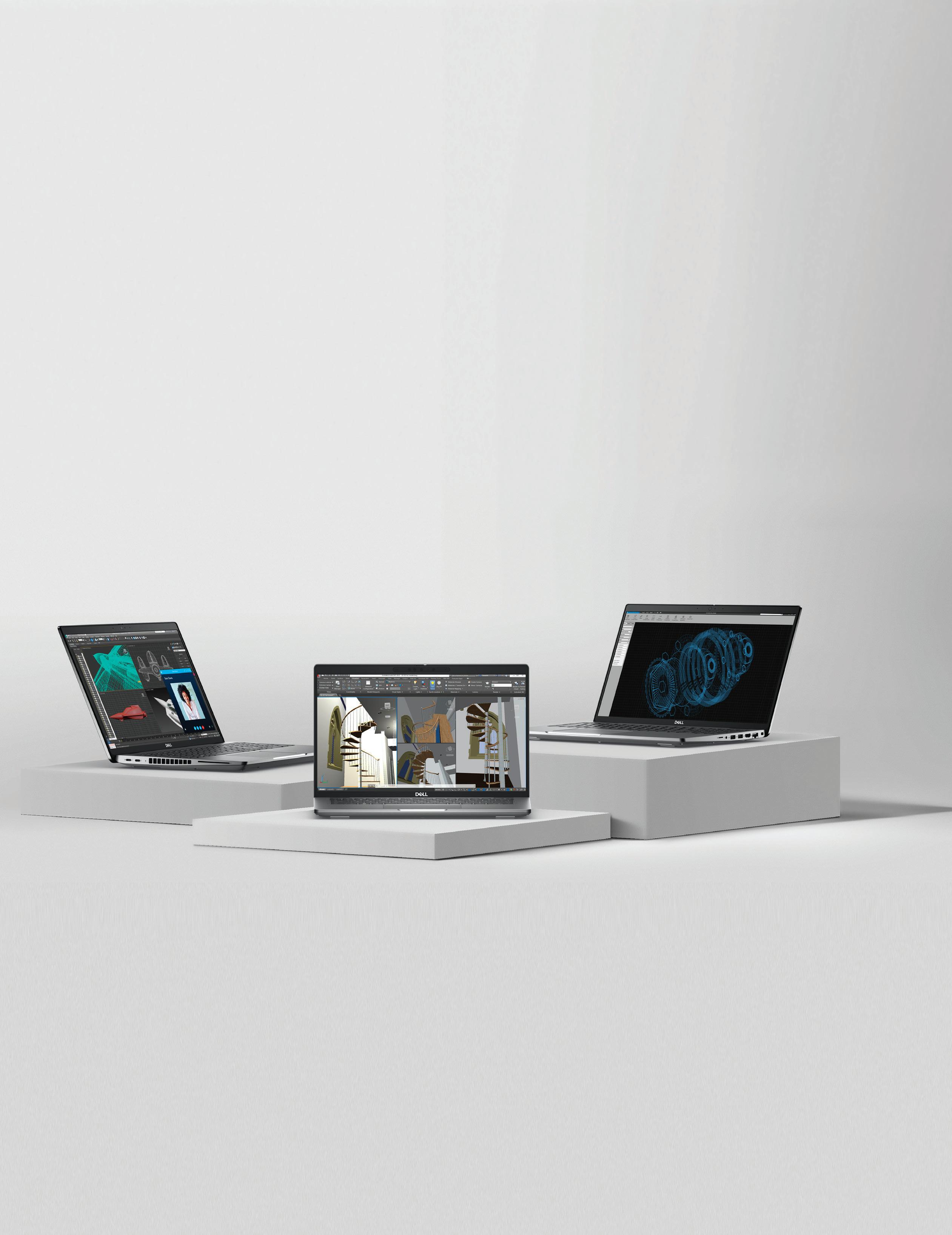

Exclusive savings available for AUGI users at www.Dell.com/AUGI
PRECISION 3000 SERIES MOBILE WORKSTATIONS IT ALL HAPPENS ON PRECISION
Autodesk AutoCAD sold separately


augi.com/augiworld April 2024 | AUGIWORLD Magazine 3 CONTENTS 8 14 20 April 2024 AUGIWORLD FEATURES 8 BricsCAD Enhance Efficiency, Productivity, and Reinvest Through BricsCAD Pro Integration 14 BCM Shared Coordinates (Still) Help Achieve Project Success 20 Revit MEP What MEP Needs from Your Architectural Model 30 Free Samples The Spring Edition COLUMNS 4 Letter from the Editor 6 Tech Manager 39 Inside Track
Letter from the Editor

Great topic for this month, collaboration. We collaborate on a daily basis. Whether it be, how to tackle a project, or collaborating with the wife as to “where do you want to eat?”. We definitely know the answer to that question!
Collaboration contributes to employee satisfaction. They feel appreciated for their abilities and input. This goes along with the new remote work environment. When collaboration is done in a positive atmosphere, they are more likely to meet project deadlines. Working with a team that has a wide range of talent makes solving problems easier and faster than working solo.
On another note, I would like to welcome our new AUGI President, Eric DeLeon. Eric has been on the board with us for a couple of years now. Thanks for all you do Eric! And I would also like to thank our former president, KaDe King. KaDe did a lot of great things for AUGI. She will remain on the board for now. Thank you KaDe for your years of service as the president.
With that, I hope you enjoy this month’s issue and keep those collaboration meetings going full force!!
Editor-in-Chief
www.augi.com
Editors
Editor-in-Chief
Todd Rogers - todd.rogers@augi.com
Copy Editor
Isabella Andresen - isabella.andresen@augi.com
Layout Editor
Tim Varnau - tim.varnau@augi.com
Content Managers
3ds Max - Brian Chapman
AutoCAD
Civil 3D - Shawn Herring
BIM/CIM - Stephen Walz
BricsCAD - Craig Swearingen
Dassault Systèmes - Rafael Testai
Electrical - Mark Behrens
Manufacturing - Kristina Youngblut
Revit Architecture - Jonathan Massaro
Revit MEP - Jason Peckovitch
Tech Manager - Mark Kiker
Inside Track - Rina Sahay
Advertising / Reprint Sales
Kevin Merritt - salesmanager@augi.com
AUGI Executive Team
President
Eric DeLeon
Vice-President
Frank Mayfield
Treasurer
Todd Rogers
Secretary
Kristina Youngblut
AUGI Board of Directors
Eric DeLeon KaDe King
Chris Lindner
Frank Mayfield
Todd Rogers
Scott Wilcox
AUGI Advisory Board of Directors
Shaan Hurley Shelby Smith
AUGIWORLD Magazine | April 2024 augi.com 4
Publication Information AUGIWORLD magazine is a benefit of specific AUGI membership plans. Direct magazine subscriptions are not available. Please visit www.augi.com/account/register to join or upgrade your membership to receive AUGIWORLD magazine in print. To manage your AUGI membership and address, please visit www.augi. com/account. For all other magazine inquires please contact augiworld@augi.com Published by: AUGIWORLD is published by AUGI, Inc. AUGI makes no warranty for the use of its products and assumes no responsibility for any errors which may appear in this publication nor does it make a commitment to update the information contained herein. AUGIWORLD is Copyright ©2024 AUGI. No information in this magazine may be reproduced without expressed written permission from AUGI. All registered trademarks and trademarks included in this magazine are held by their respective companies. Every attempt was made to include all trademarks and registered trademarks where indicated by their companies. AUGIWORLD (San Francisco, Calif.) ISSN 2163-7547
AUGIWORLD
Kristina Youngblut



A Global
for AEC
and Exchange
Become
Community
Professionals to Learn, Grow
Knowledge.
a member: www.dbei.org/membership
Mark
Budget Prep

Every year I have to provide a budget to upper management that outlines where spending should be focused on tech in the coming year. It includes items that must be done, like continued subscription for software, and things that should be done, like replacing old hardware. It also includes things that would be nice to have, like visualization tools and high-end tech. I wrote on this back in December 2019 and January 2021, but now I will discuss the prep steps needed to usher in your budget request.
As I prep the documents for defining and presenting my budget for approval, I know that there has to be some groundwork done all year long to make the budget requests more likely to be approved. There is never a guarantee that everything on my budget will garner approval or have the money to actually spend when it comes time to buy, but there are some things that I can do to soften the bottom-line decisions that management and finance has to make. Here are the suggestions based on my past successes and missteps.
PROVEN LEADERSHIP TRACK RECORD
Not only do you have to actually provide good leadership, but you also have to sometimes prove it. This means letting people know where you are headed, how you will get there, actually getting there and reminding them that you got there. All without being boastful. You do this by having a plan, working the plan, and celebrating successes with others. By having a good track record, people will tend to trust you and grant you authority over projects, staff and budgets.
Sometimes money is the last authority you might gain. Being able to define what money will be spent on which tech is a privilege. You will always have limits given by others, but you strive for flexibility under an overall fund balance. Step out in your leadership by defining future steps and then execute. Trust will follow and then money will follow that.
MAKE PERSONAL CONNECTIONS WITH UPPER MANAGEMENT
Get to know those that you serve. I am not diminishing the need to stay connected to the frontline staff and your peers, but upper management connections are critical. Especially when it comes to spending money. Your budget will need to go up the ladder and land on the desks of many executives that can make or break your efforts. They may not have a real grasp on the technologies you are proposing, but they will be able to say “no” to the funding of those technologies.
When they are reviewing your proposed budget, it they may not realize the planning, effort, projections, and crystal ball thinking that went into your numbers. But they will know you. If your track record is good and you have built relationships, it will help nudge the decision process your way. Upper management must balance many areas that are clamoring for funds. They weigh many needs against other needs. They may have to make tradeoffs. When it comes down to deciding between one area or another, your personal relationship with them might help them lean toward your needs.
You don’t have to be best friends, just make sure they know what you have done in the past, that
AUGIWORLD Magazine | April 2024 augi.com 6 by:
Kiker Tech Manager
you care about the future of the company and that your requests are well thought out. Keep the relationships alive by chatting from time to time or having lunch together.
PROVIDE GOOD FINANCIAL REPORTS
From time to time, you need to provide a brief report on how your budget is progressing. Be real and honest about your progress and include a projection for the rest of the financial year. Include what was already spent and what was achieved. Define what is coming next. Let them know where you have saved money and how it might be used on something better. Include things that cost more than you budgeted and where the money might come from to keep the budget balanced. One page max, graphics help. Offer to go over the numbers in detail if they request that. Your reports should demonstrate that you have a track record of fiscal responsibility and successful results.
PROVIDE ROI JUSTIFICATION
You may need to justify your budget, so be prepared to provide Return on Investment (ROI) documents. You should be able to define how long it will take to cover the cost of what you are buying. If you want a new plotter, then calc the speed gains per plot, multiplied by the number of plots per day/month and then calc the time/labor saved and outline that as money. Saving 30 hours a month can be converted into average salary savings on labor (not having to stand there waiting for a plot to finish).
This may also mean defining Total Cost of Ownership (TCO) calcs. TCO is what it really costs to have this tech in place. If it is a new plotter, define the cost per plot or that cost of buying supplies, add maintenance and whatever else. This is the true cost, not just the price of the hardware.
When discussing possible budget inclusion, be sure to talk about what “doing nothing” will mean. Will it impact another tech effort? Projects? What about continuing to use old tech. does it increase costs due to maintenance? Keep in mind that not including something in the budget means that you need to let folks know what a delay in progress can mean.
Also think about what will cascade out of your budget. Will replacing one piece of tech mean you will soon need to replace another? And also think about what you would remove if they needed to
get your overall number lower. Prep for removals, or others might make that decision for you.
DON’T INTRODUCE NEW TECH
What? Aren’t we supposed to have new tech in our budget? Yes, you do need new tech and progressive ideas in your budget. What I mean is don’t use the budget to introduce new tech conversations. That should be done in the Strategic Planning discussions. Don’t just drop something into the budget that has not been mentioned before. You need to lay the groundwork for new items. Go back and read my articles on Strategic Planning. That always comes before the budget line items.
PROVIDE A BUDGET (EVEN IF THEY DON’T ASK FOR ONE)
I provided budgets to management even before they asked for them. They may not have cared, and they may only have a bottom-line max in mind, but it displayed the fact that I was thinking long term in managing money, not just tech. After a few years of doing this, they started asking me to be part of the firms budgeting process.
CONCLUSION
With today’s tech enabled firms, the largest portion of spending, after personnel cast, is usually technology. You need to be part of the process. By prepping all year long and providing solid data, you can and should be part of your firm’s efforts in defining where the money is spent.

Mark Kiker has more than 35 years of hands-on experience with technology. He is fully versed in every area of management from deployment planning, installation, and configuration to training and strategic planning. He is an internationally known speaker, writer and former AUGI Board member and president. Mark is currently serving as Chief Technology Officer for SIATech, a non-profit public charter high school focused on dropout recovery. He oversees two web sites, www.caddmanager.com and www.bimmanager.com. He can be reached at mark.kiker@ augi.com and would love to hear your questions, comments and perspectives.
augi.com/augiworld April 2024 | AUGIWORLD Magazine 7 Tech Manager
by: Craig Swearingen
Enhance Efficiency, Productivity, and Reinvest Through BricsCAD Pro Integration

As businesses increasingly strive for innovation and cost-effectiveness, Bricsys BricsCAD® has emerged as a reliable ally for architects, engineers, and designers around the world. Through its commitment to providing state-of-the-art solutions, Bricsys® has successfully bridged the gap between functionality and user-friendly design, earning the trust of a diverse clientele.
In this article, we delve into how Bricsys has left an indelible mark on the global design landscape and explore how BricsCAD® Pro, their flagship product, continues to be an indispensable tool for professionals seeking to elevate their production processes to new heights. From its inception, Bricsys has been steady in its dedication to empowering users with tools that not only meet but exceed their evolving design needs. If that isn’t enough, discover how BricsCAD also allows companies to reinvest in themselves and their employees. So, let’s unravel the story of how BricsCAD Pro has become the linchpin of innovation for forward-thinking individuals and organizations worldwide.
ACHIEVING COST SAVINGS AND ENHANCED PRODUCTIVITY WITH BRICSCAD PRO
Byucksan Engineering is a leading engineering company in Korea with over 40 years of experience. Their use of BricsCAD Pro, a powerful and affordable CAD software, has improved their productivity and reduced operating costs.
Byucksan Engineering, established in 1979, is a leading engineering company in Korea with 50 perpetual BricsCAD Pro licenses used across the business. The company has a strong track record of delivering complex projects in a variety of industries, including plants, power plants, environments, roads, water supply and sewage, urban railway and electric power, and housing & construction. (See Fig.1)
Byucksan Engineering’s ethos is centered around pride in Korea’s engineering technology industry. The company invests heavily in research and
AUGIWORLD Magazine | April 2024 augi.com 8
BricsCAD

development and constantly innovates to stay ahead of the competition. Byucksan Engineering is also a leader in social responsibility and is committed to making a positive impact on the communities in which it operates.
We spoke with Choi Seong-gil from the Byucksan Engineering Piping Team about using BricsCAD Pro. Seong-gil detailed how BricsCAD has helped the company to improve its productivity and reduce its costs. (See Fig.2)
THE CHALLENGE
Byucksan Engineering used its previous CAD software for over 20 years. However, due to their
supplier changing their license agreement alongside the evolving needs of their CAD users, they began to look for an alternative better suited to their needs.
The company considered many factors while searching for an alternative CAD solution, including stability, performance, license policy, and price. BricsCAD proved a workable option on all fronts, so Byucksan opted for a trial version of BricsCAD to test drive the functionality and user interface.
THE SOLUTION
After a thorough investigation and testing throughout the trial period, Byucksan Engineering found that BricsCAD was indeed a viable alternative to their existing CAD software for the following reasons:

Productivity and drawing optimization features: BricsCAD includes productivity functions and drawing optimization functions that were not in their existing CAD software. These functions helped to automate tasks and improve the efficiency of their design workflow.
Performance: BricsCAD provided the same stability as Byucksan Engineering’s existing CAD software and was even faster when opening or saving large-capacity drawings. This improved the performance of their CAD applications and allowed them to complete their projects more quickly.
augi.com/augiworld April 2024 | AUGIWORLD Magazine 9
BricsCAD
Figure 1
Figure 2
BricsCAD

Customizability: BricsCAD has a free API and its own CAD engine, making it perfect for future CAD-based in-house program development. This has allowed Byucksan Engineering to customize BricsCAD to meet their evolving business needs.
Compatibility: BricsCAD is compatible with a wide range of other software applications, making it easy to integrate into Byucksan Engineering’s existing workflows and with other third-party apps that the company relies upon.
Cost-effectiveness: BricsCAD offers reasonable pricing and flexible licensing policies, which helped Byucksan Engineering reduce its initial CAD purchase and ongoing operating costs.
Ultimately, BricsCAD proved to be an excellent choice for Byucksan Engineering as it could replace

their existing CAD product while maintaining their existing workflows. (See Fig.3)
Results
Notably, the company has found great advantage in BricsCAD’s wide range of third-party applications, of which there is something to suit almost any requirement.
“There was a CAD-based 3rd party app that I had to use, and I was impressed that BricsCAD was perfectly compatible”.
The flexibility of a network license was a huge plus for Byucksan, reducing their CAD operating costs significantly. A stark contrast to their previous CAD license costs, which were required to be maintained on an annual basis. The flexibility of BricsCAD really comes to the fore when, as is often the case, project requirements change. Seong-gil comments:
“Even when additional licenses are needed, such as staffing or new projects, (with BricsCAD) additional licenses can be reasonably purchased based on the number of concurrent users”.
Across the board, Byucksan’s teams have been able to reap the benefits of implementing BricsCAD solutions, with Seong-gil remarking:
“The feeling of BricsCAD is that it is flawless and a very cost-saving software”.
LEADING FRENCH SURVEY FIRM, OPERANDI®, INTEGRATES BRICSCAD PRO INTO THEIR TECHNOLOGY TOOLSET

Operandi®, a leading French survey firm, switched to BricsCAD Pro to deliver landmark survey projects across the city of Lyon.
Operandi switched out their legacy CAD for BricsCAD Pro, a key part of their multi-vendor technology toolset used to deliver landmark survey
AUGIWORLD Magazine | April 2024 augi.com 10
Figure 3
Figure 4
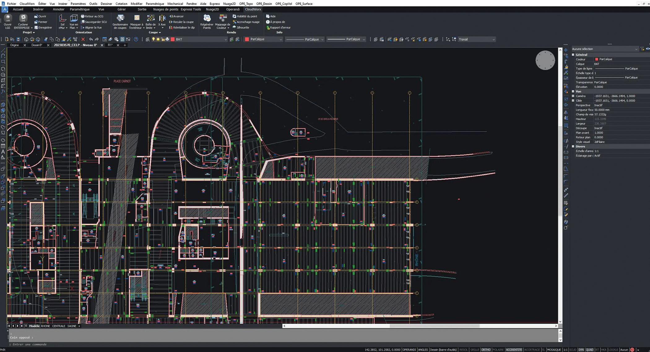
projects across the city of Lyon. With seamless 2D/3D DWG interoperability and the ability to import and export other industry file formats, the company could easily integrate BricsCAD into its multi-vendor workflow. (See Fig.4)
Operandi is a Survey company based in Lyon, France, with expertise in urban development from architectural surveys and model creation to topographical surveys and plot divisions.
THE CHALLENGE
With increased licensing costs from their existing CAD vendor, including a move to named licensing, Operandi’s search for an alternative CAD solution had the additional challenge of integrating with their complex technology toolset.
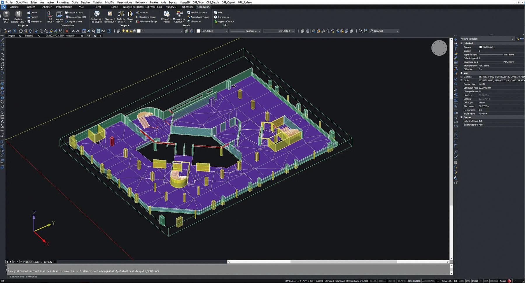
Operandi uses survey instruments from Leica and other manufacturers, alongside specialist processing software to merge and create highly detailed models as part of their diverse service offerings. Additional software could also be used to deliver the final output, depending on the customer’s requirements. As such, any alternative CAD solution would need to integrate into their workflows seamlessly. (See Fig.5)
THE SOLUTION
The task of finding an alternative CAD was given to two graduates who reviewed the company’s needs and available alternative solutions. After a detailed assessment of existing integration requirements and the functionality needed within the CAD software, BricsCAD came out as the best solution to their needs.
The company’s CAD workflow would typically involve editing and marking up models created from field data. The scanned data would normally be collected using Leica instrumentation and stitched together in Cyclone REGISTER 360, with further processing taking place in CloudWorx before being edited in their CAD software. This workflow would vary depending on the use of other instrumentation.
Following the review project’s outcome, some longstanding employees were concerned that the change would impact on their productivity. However, after a short period of adapting to the change, they found they were as productive as before.
The leadership team at Operandi recommends involving the employees as much as possible in deciding to support the adoption process, as they all understand the motivation for the change. (See Fig.6)
augi.com/augiworld April 2024 | AUGIWORLD Magazine 11 BricsCAD
Figure 5
BricsCAD
RESULTS
The most important aspect of the move for the leadership team was that the change to BricsCAD didn’t interfere with the complex multivendor workflows. They successfully transitioned and benefited from savings, representing 3.5% of their total revenue – equivalent to the company’s entire employee profit-sharing plan.
MORE ABOUT BRICSCAD
Bricsys BricsCAD is professional CAD software without compromise. Accelerate your time to deliverable without compromising on performance, cost, licensing flexibility, and data security. Not ready to buy? Download the free, 30-day trial of BricsCAD at Bricsys.com. Would you like free lessons? We have that available with Bricsys Learning. Ready to migrate to BricsCAD? Download the Migration Guide. The latest version of BricsCAD improves the tools and features users love, as well as new functionality and UI that supercharge productivity. Follow us today on LinkedIn and Youtube.
MORE ABOUT BRICSYS
Bricsys, part of Hexagon®, is the global technology company that creates the BricsCAD family of computer-aided design (CAD) products and the Bricsys® 24/7 project collaboration platform. We
are relentlessly committed to the success of our customers by offering cost-effective, missioncritical CAD software with industry-leading product support. Learn more at www.Bricsys.com.
Hexagon is a global leader in digital reality solutions. Learn more about Hexagon (Nasdaq Stockholm: HEXA B) at hexagon.com and follow us @HexagonAB.

Mr. Craig Swearingen is a Global Implementation Specialist and Consultant at Bricsys®. Currently, Craig provides migration and implementation guidance, management strategies, and technical assistance to companies which need an alternative, compatible CAD solution. Craig spent 19 years in the civil engineering world as a technician, Civil 3D & CAD power user, becoming a support-intensive CAD/ IT manager in high-volume production environments. Craig is a longtime AUGI member (2009), a Certified Autodesk® AutoCAD® Professional, and he enjoys networking with other CAD users on social media.
AUGIWORLD Magazine | April 2024 augi.com 12
Figure 6
Bright Ideas for a Bright Future

AUGIWORLD brings you the latest tips & tricks, tutorials, and other technical information to keep you on the leading edge of a bright future.
by: Jonathan Massaro

Shared Coordinates (Still) Help Achieve Project Success
In December 2015, I wrote an article for AUGIWORLD titled Shared Coordinates and Civil State Plane Coordinates which highlighted the power of using shared coordinates and alignment with actual state plane coordinates in Autodesk® Revit®. I also explained how to use shared coordinates with CAD civil files to enhance workflows with the civil engineering members of a project team. Over the last decade, Revit has rolled out numerous new tools and features. That’s why I’m back to share a simplified, updated workflow for working with shared coordinates because none of those new tools help us with this. Maybe except for one.
BACK TO THE BASICS
“Shared coordinates” is a BIM buzzword, and many people struggle to understand how they function on a project. Here’s the lowdown: within the Revit
environment, shared coordinates use geolocation to ensure alignment of multiple models—either between Revit models only or between Revit models and AutoCAD site/civil content—when they enter the building coordination model (BCM) environment.
A BCM is a host file used for virtual cross-checking between various design team disciplines and understanding the building’s relationship to true north. When setting up a BCM, the main goal is to create a Revit environment that uses a civil drawing as the model’s underlay and locate the building on the site. Shared coordinates are exclusive to the BCM, in this workflow, and are not present in linked models, such as the architectural scope model. The exception is when exporting models to CAD using shared coordinates, which must be done from the BCM using linked views.
AUGIWORLD Magazine | April 2024 augi.com 14 Revit Architecture
Consultants are often asked to set up specific views to be used in the BCM to export. To establish those views, every consultant model is required to be linked and located in the BCM, aligned over the correctly placed architectural model. By restricting shared coordinates to the BCM, teams can link all scope models to each other using “origin to origin,” preventing shared coordinates from breaking between scope models throughout the life cycle of the project.
GETTING STARTED
At the beginning of a project, the architectural model should be linked into the BCM. To set the coordinates in the BIM environment, the civil engineer must provide the architect with two points to set the survey and project base points. The chosen points require northing/easting coordinates and elevation and should be from permanent real-world features that will remain post-project— not items that may be removed during the design process. For example, a property corner or benchmark outside the work area is recommended. Additionally, True North needs to be illustrated to align it in the Revit model, showing the difference from Project North, which is always upward in view.
After the engineer establishes the initial building location, the architect should provide a clear building footprint, exported to DWG for the civil site engineer. Then, discipline models can be compiled and positioned in the BCM—over the architectural model—using gridlines. All subsequent exports from consultants’ files must be executed from the BCM.
STEP-BY-STEP GUIDE TO SETTING UP SHARED COORDINATES
Setting up your BCM
1. Create a BCM file from a new model and save it to the folder where the scope model is saved.
2. Change the project units to “feet” and rounding to “custom,” and type “0.0001” as the rounding increment.
3. Choose the view for the site plan and make
sure the orientation is set to “True North.”
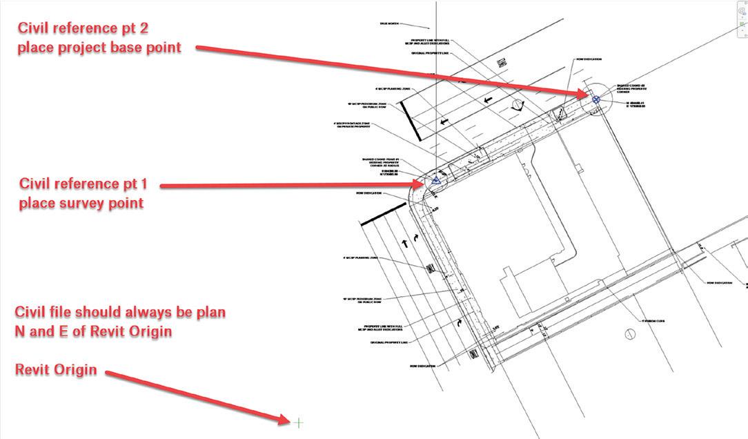
4. Link the cleaned version of the civil CAD plan to the BCM, center to center. Make sure the civil file is North and East of the Revit origin point in the BCM.
5. Link the architectural model(s) to the BCM, origin to origin.
6. Unclip the project base point and survey point; move the survey point to the first reference point on the plan.
7. Move the project base point to the second reference point on the plan (Figure 1).
Importing Shared Coordinates
8. Link architectural Revit model to the BCM and align it to the building footprint in the linked civil file. The model may need to be rotated to align with the civil file.
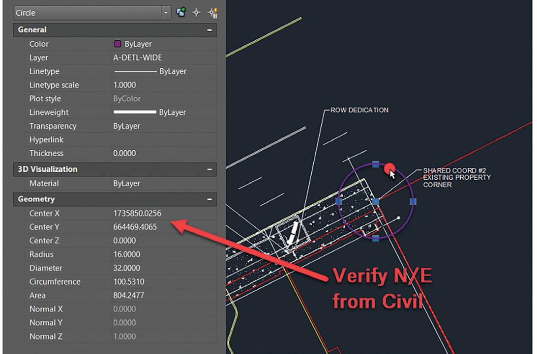
9. Using model lines, draw a circle around the two reference points. These will need to be exported in a CAD file for testing purposes and should remain in Revit for reference.
10. Use the “shared reference point” tool located on the “add-ins” tab to import the shared coordinates from the XML file (Figure 2).
On the bottom left corner of the Revit window, the prompt “Select ORIGIN point to align to” will appear. Select reference point 1.

augi.com/augiworld April 2024 | AUGIWORLD Magazine 15
Revit Architecture
Figure 1
Figure 2
Revit Architecture
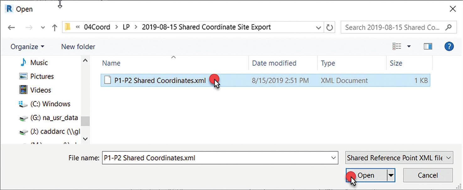


Next, the prompt “Select a Point on +Y (Up) Direction to align to” will appear. Select reference point 2. Make sure to select the exact point or intersection of the two points—otherwise, the coordinates will be off. When a dialog box appears, select the XML file provided by the civil engineer (Figure 3).
Select yes, then click “ok" (Figure 4).
11. From the “manage” tab, select “location” and fill in the project address. Then, select the “site” tab and pick the name that corresponds with the XML file and make current (Figure 5).
Verifying Coordinates in Revit
12. Select the survey point (triangle) and review the properties information under “identity data.” The N/S value and the E/W value should match the northing and easting from the civil file.
13. Verify the northing and easting at your project

AUGIWORLD Magazine | April 2024 augi.com 16
Figure 3
Figure 4
Figure 6
Figure 5
Revit Architecture
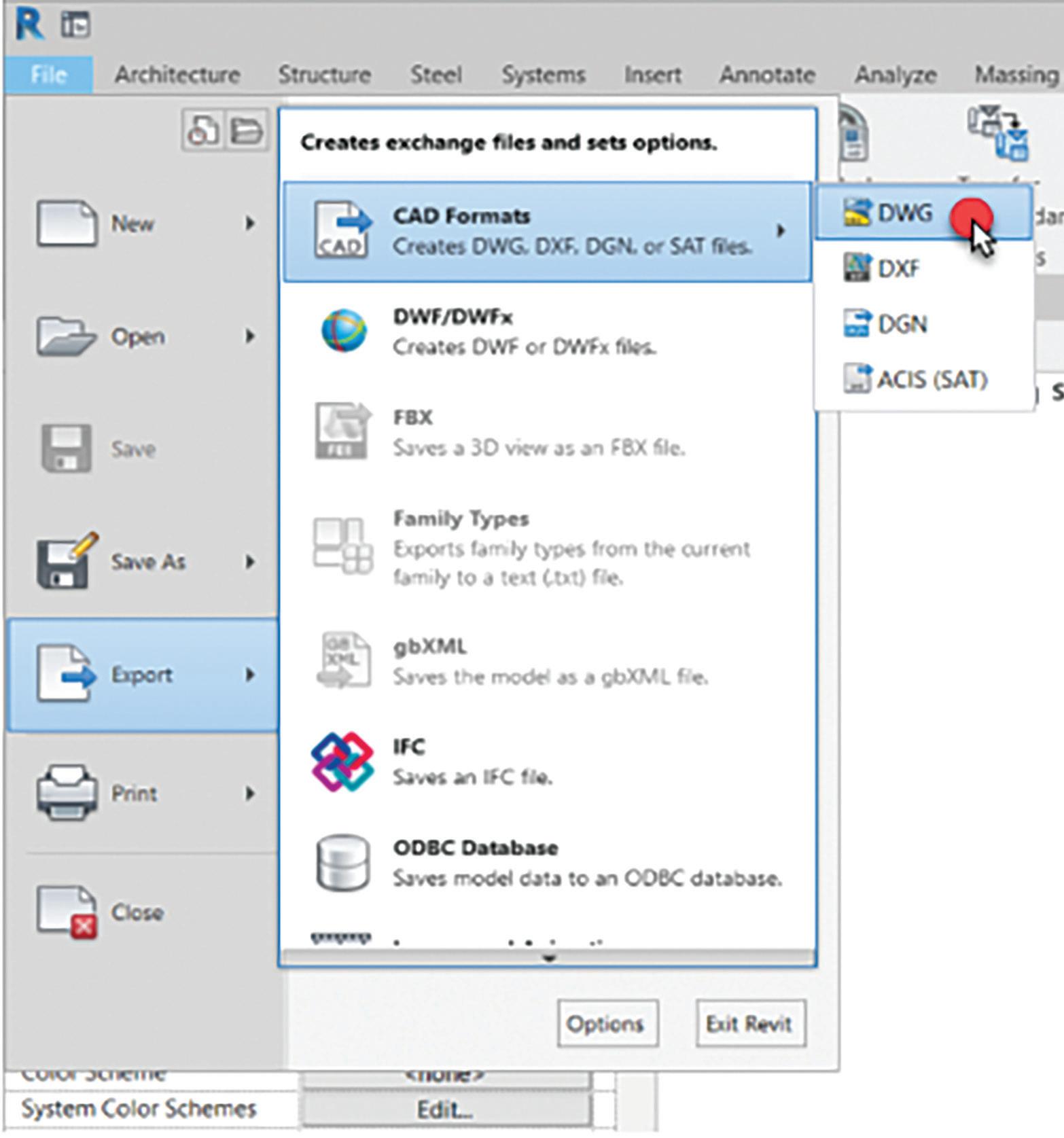
basepoint where reference point 2 is located.
14. Switch to an elevation view and align the model level with the matching survey point elevation (Figure 6).
15. If everything is correct, attach and pin the paperclip to the project basepoint and survey point.
Exporting back to CAD for final verification and Civil use
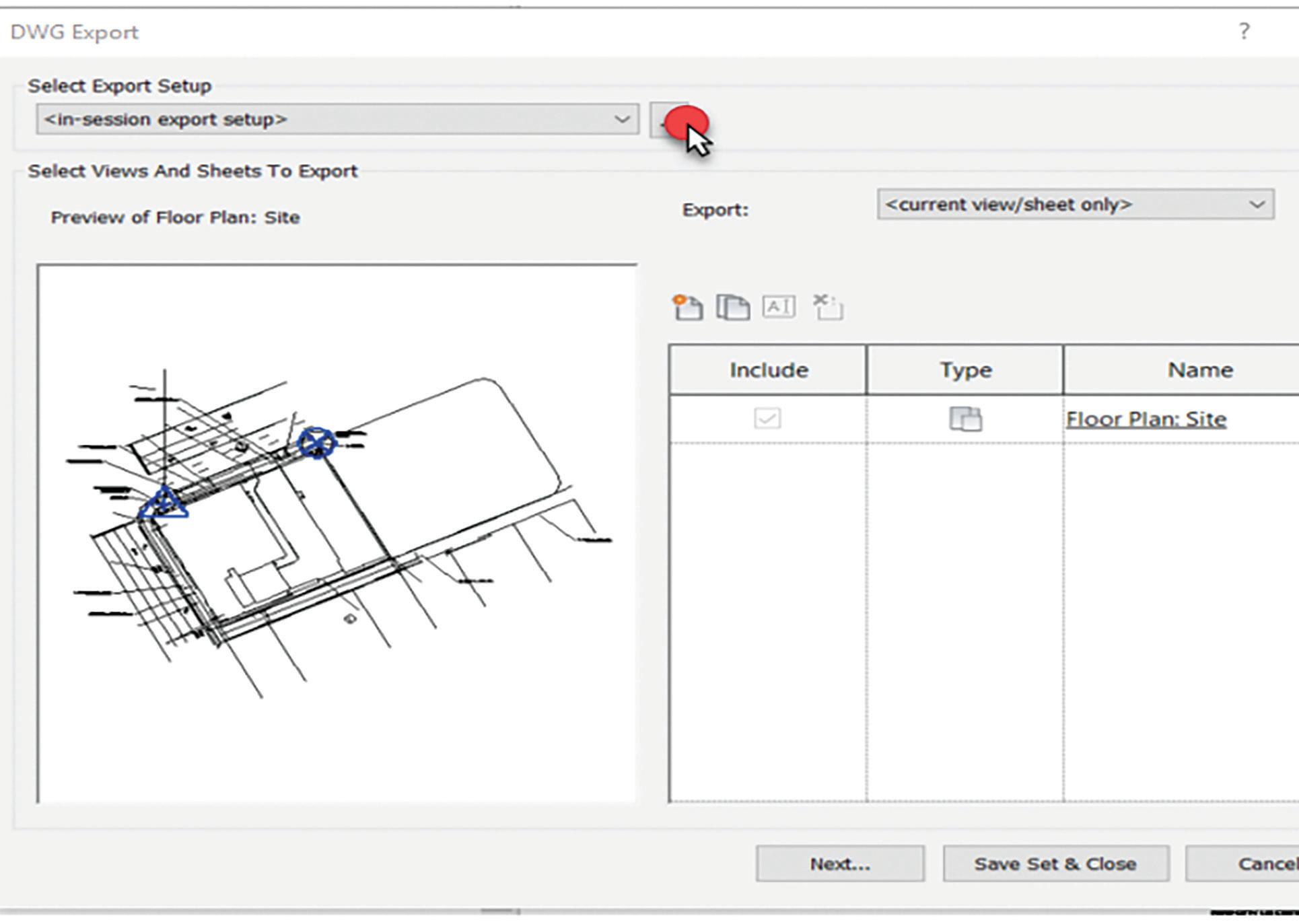
16. To verify you’ve done this correctly go to File > Export > CAD Export > DWG. This should export the site view used to bring everything in with the civil plan (Figure 7).
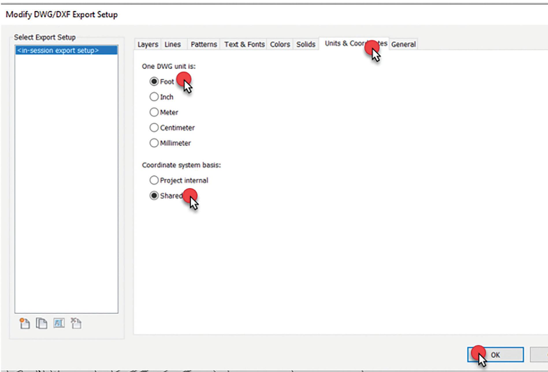
17. Select the “…” button to access the “modify DWG/ DXF export setup” settings (Figure 8).
18. Select the “Units & Coordinates” tab and change the defaults to “foot” and “shared,” then click “ok" (Figure 9).
19. On the DWG export dialog, select “next."
20. Uncheck the box that says “export views on sheets and links as external references” and save the CAD file to your project folder.
Verifying Coordinates in AutoCAD
21. In AutoCAD, open the file you just exported to verify the position.
22. Type “units” and set the length type to “decimal”, set precision to “0.0000” and set the insertion scale to “feet.”
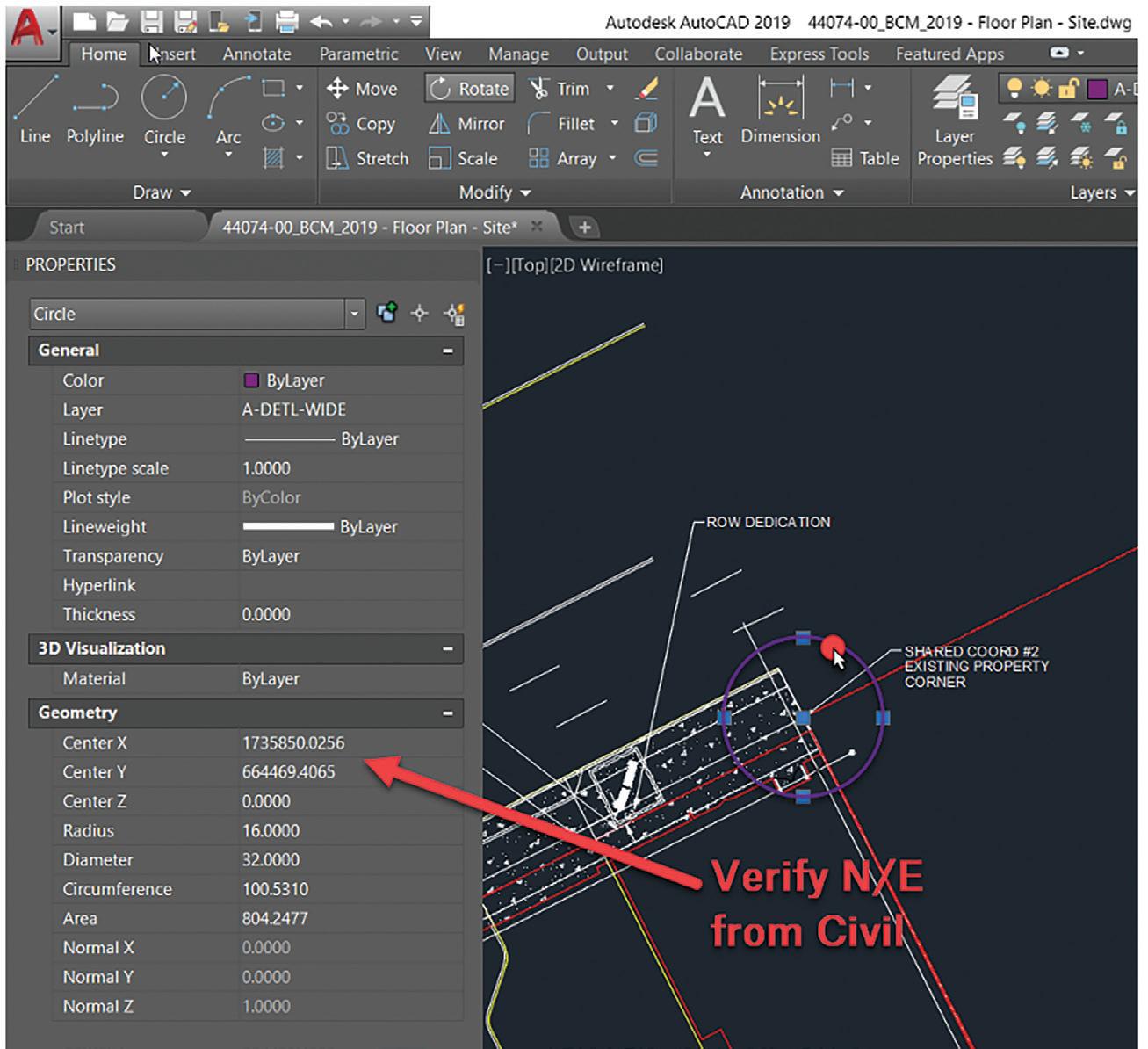
23. From the exported site view, select one of the circles around the reference points and then review the geometry section of the properties under “Center X
augi.com/augiworld April 2024 | AUGIWORLD Magazine 17
Figure 7
Figure 8
Revit Architecture
(Northing) Center Y (Easting).” They should match the Civil file. If they do not match, review the previous steps (Figure 10).
All Other Revit Disciplines
Pro
Tip:
Prior to starting these steps, have your consultant set up a view, or views, with the objects needed for civil coordination—including grid lines— so you can align their model to yours. The, set the visibility graphics to “by linked view” to export what is needed and enable consultants to show what they intend to coordinate with civil.
24. Open the Building Coordination Model.
25. From the site plan view, link the consultant model to the file using “manual center” for the position option and place the model near the architectural model.
26. Position the consultant model using some predetermined reference marks, like column grids, to align the models.
27. Insert other consultant models as needed using the previous steps.
28. Duplicate the site view for each CAD file you need to export. This isn’t required each time, only for each type of export needed. (i.e. foundation, plumbing, architectural footprint.)
In conclusion, shared coordinates are a powerful tool in Autodesk® Revit®, allowing for alignment of multiple models within the Building Coordination Model (BCM) environment. By following the steps outlined above, architects and civil engineers can better collaborate and elevate their design solutions.

Jonathan Massaro is a Senior Design Technology Specialist and Associate with Gresham Smith, a leading multidisciplinary design and consulting firm for the built environment. He has worked in the architectural field for almost 30 years on projects of various size and type ranging from single family homes to airport terminals, and he began working in Revit with Revit Architecture 2009. He was initially hired by Gresham Smith to work on some of the first Revit projects for the firm’s Healthcare Division back in 2011. Currently a part of the Gresham’s Practice Technology group, Jonathan works on supporting all the Architectural markets and works to help streamline the firms Revit workflows and processes.
AUGIWORLD Magazine | April 2024 augi.com 18
Figure 9
Figure 10

AUGI Members Reach Higher with Expanded Benefits
AUGI is introducing three new Membership levels that will bring you more benefits than ever before. Each level will bring you more content and expertise to share with fellow members, plus provide an expanded, more interactive website, publication access, and much more!
Basic members have access to:
• Forums
• HotNews (last 12 months)
• AUGIWORLD (last 12 months)
DUES: Free
Student members have access to:
• Forums
• HotNews (last 24 months)
• AUGIWORLD (last 24 months)
• AUGI Educational Offerings
DUES: $2/month or $20/year
Professional members have access to:
• Forums
• HotNews (full access)
• AUGIWORLD (full access and in print)
• AUGI Library
• ADN Standard Membership Offer
DUES: $5/month or $50/year
Are you ready to upgrade yourself and your membership?
Access additional benefits and upgrade at www.augi.com
Jason Peckovitch
What MEP Needs from Your Architectural Model

Collaborating with various disciplines, both internally and externally, is an essential aspect of project success. As an architect, it is imperative to ensure that your actions are supporting the efforts of other teams, particularly MEP, to minimize the need for rework. In this article, we will explore how the architectural and structural aspects of a project impact critical workflow processes and provide insights on how to optimize collaboration with these teams for greater project efficiency.
OUR BASIC DESIGN WORKFLOW
After the contract is awarded, we initiate our basic design workflow, which consists of four main phases: schematic design, design development, construction documentation, and construction administration. In each phase, we work closely with our client and other disciplines to ensure that the design meets the project requirements, budget, and schedule. We also use various tools and techniques, such as BIM, clash detection, and energy analysis, to enhance the quality and efficiency of our design process. If I were to list out our basic process which can vary from firm to firm,
it would look like below.
• Proposal Acceptance/Contract Awarded
• Project Kick-off Meeting
• Our project kick-off meeting consists of our project team and our client, whether they are internal or external.
• Project Setup
• When I set up a project, I typically will use the Architect’s model using their title block, matching their view naming, view placement on sheets, sheet numbering and naming.
• Internal BIM Kick-off Meeting
• The internal BIM project kickoff is where we discuss project needs and how the project was set up.
• Our Design Process Starts
• During the life of the project, our design will probably change 3-4 times or more.
THE IMPORTANCE OF KICK-OFF MEETINGS
Kick-off meetings are when the project collaboration really begins, and you may be meeting the rest of the team for the very first time
AUGIWORLD Magazine | April 2024 augi.com 20 Revit MEP by:

at this meeting. There are plenty of important project related topics that should be discussed during the project kick-off meeting.
BIM Execution Plan (BEP/BXP)
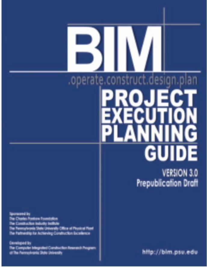
Even after all these years, companies and subsequently a lot of projects are still not issuing a BIM Execution Plan. Why is that? Is it because they don’t have time to develop one? Do they think they are not necessary? I am sure if you ask someone from any firm, you will get a myriad of different
reasons as to why or why not for their use. If you are not using one for projects, what are your reasons? Without getting into specifics, because I assume those that are attending, already know what a BEP/ BXP is already. If there is no BXP, when there is no BXP present for the project, here are some of our more crucial topics to discuss.
Level of Detail
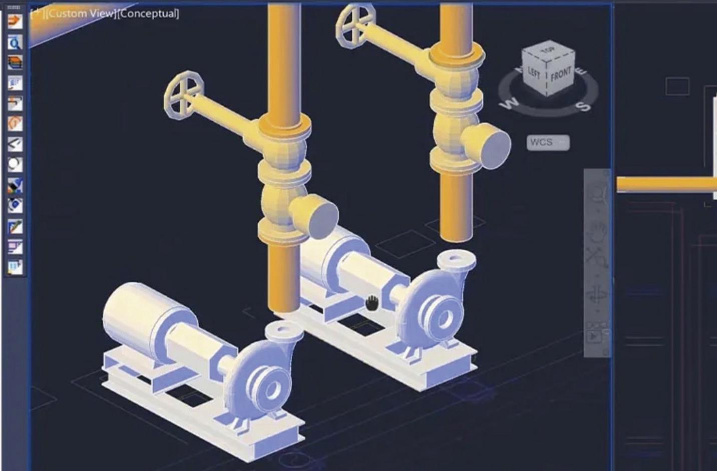
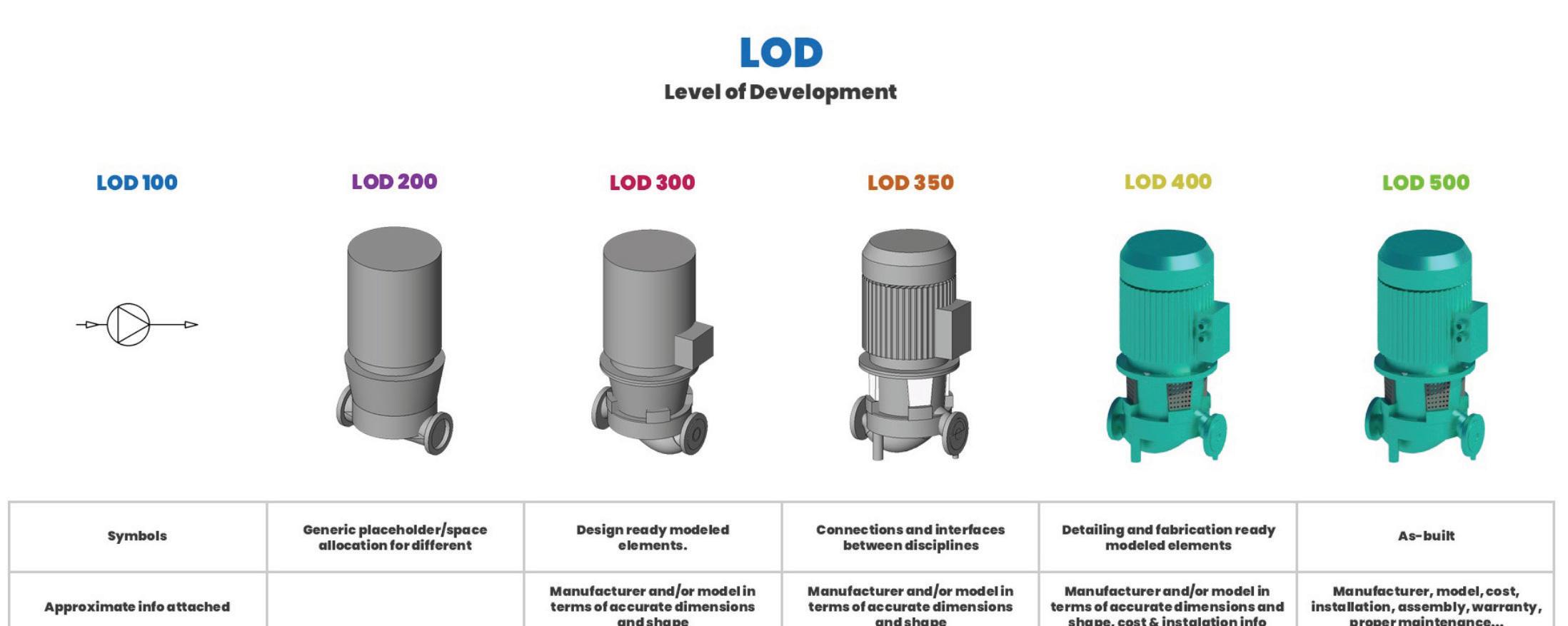
In my experience working at various companies the past 17 years that utilized Revit, most families developed were in the LOD 200-300 range. While they may visually resemble LOD 200 pumps, the model and family information included corresponded to LOD 300-350.
In the context of an MEP (Mechanical, Electrical, and Plumbing) Revit model, design intent refers to the underlying concept or idea that guides the creation and development of the model. It is the intention of the designer, engineer, or architect to convey their vision and objectives for the system that will be built, installed or modified in a building.
While we could accurately model the spatial location of our piping, it would be challenging for anyone, particularly the contractor, to discern what was depicted on the sheet. Electrical drawings, on the other hand, are largely diagrammatic in nature. Due to this, most electrical families contain nested annotations as it is difficult to determine the modelled elements in a plan view. Despite providing a 3D model, our deliverables still consist predominantly of 2D representations of the design. Ultimately, our design approach prioritizes simplicity, clarity, and ease of interpretation for contractors, municipalities, and owners, while
augi.com/augiworld April 2024 | AUGIWORLD Magazine 21 Revit MEP
Revit MEP
taking into consideration time and budget constraints.
In summary, design intent is an important concept in MEP Revit modelling that helps to ensure that the resulting system is efficient, effective and meets the needs of the client and building occupants.
Model Coordination

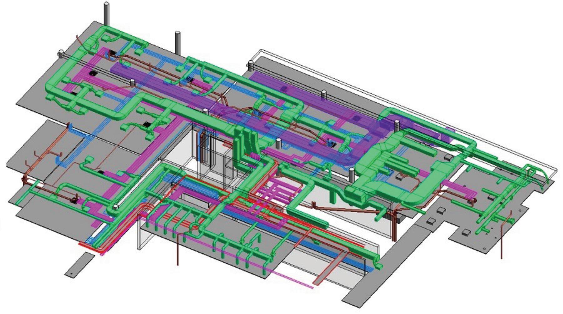
Is Model Coordination required for the project either using BIM 360/ACC, Navisworks, or some other third party coordination software? Autodesk Construction Cloud Model Coordination is great for Design Coordination whereas Navisworks is great for Constructability Coordination. Even if some level of model coordination is not required for the project, I firmly believe it is important for all parties involved to do their due diligence to ensure their design is spatially coordinated. More on that later. For MEP, this should be the norm. Lighting Fixtures should not sit in the same ceiling tile as an Air Terminal, pipe shouldn’t be running through Duct, etc, etc.
End Use of Model Considerations
• Visualization/VR/AR
• Enscape
• Twinmotion
• Workshop XR (formerly The Wild)
• Does the owner want the models?
If so, what will they be doing with it?
• Digital Twin?
• Is the General Contractor getting the models?

While owners may get the model as a deliverable, most of them do not have the capability to open them. Contractors, as I will discuss a little later, will probably redo the MEP model in their go to fabrication software. In the past I have done full 3D coordination in Revit that was quite the headache.
About 12 years ago there was a company in Denver called BIMShift that had a program called DataGate that would let you upload a Revit model to their website for model coordination and facilities asset management. It was very short lived, and they have since gone defunct. Interesting concept at the time when digital twin wasn’t even a thing yet.
Digital Twin is a fairly new industry trend that I have not found a good for it yet. Autodesk has Tandem now but I unfortunately have not been keeping up with it. When I first saw Tandem, I immediately thought of that DataGate tool I mentioned above.
Challenges with Revit and Fab Programs
Fabrication software is few and far between. There are some that are Revit add-ins and some that are independent programs. The two main programs are Revit and Fabrication CADmep and neither of these tools do not have very good interoperability without extensive and problematic parts mapping.
Other programs or tools include:
• Trimble Sysque
• AutoPipe
AutoCAD MEP
The Fabrication Parts in Revit, have little to be desired. Both programs need to be installed for that interoperability to happen. Configurations need to be created in CADmep and loaded into Revit and those configurations mapped to Revit Fab parts.
AUGIWORLD Magazine | April 2024 augi.com 22
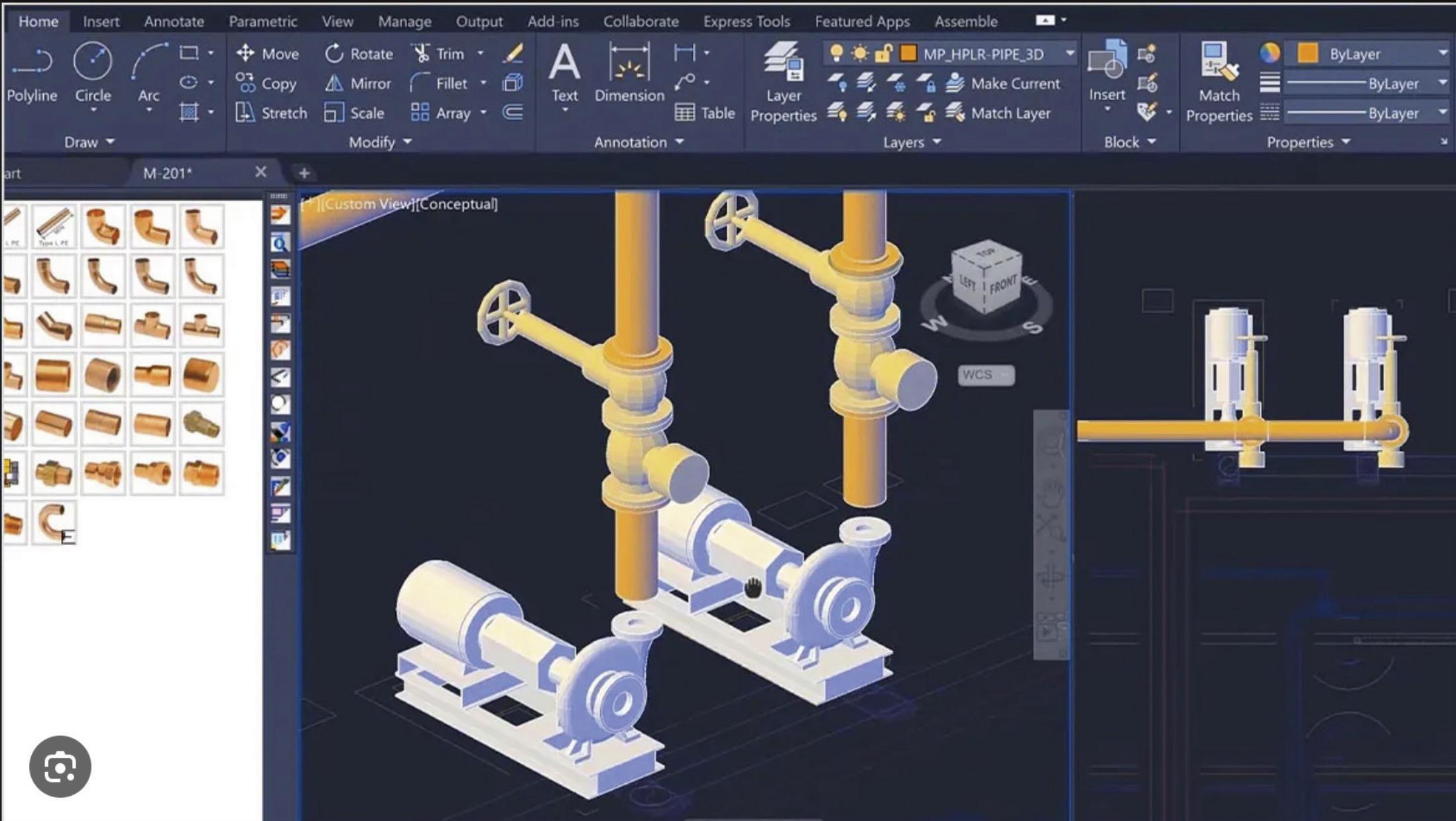
I have a concern regarding Revit Fabrication, as I am unaware of anyone currently using it. However, given the considerable amount of time and effort that Autodesk has spent, it is probable that there are users. Nevertheless, it is worth mentioning that Revit does not seamlessly integrate with the spooling software commonly utilized by contractors for duct and pipe fabrication.
Typically, before commencing construction, general contractors and their subcontractors tend to recreate our MEP (mechanical, electrical, and plumbing) models using software compatible with their specific cutting machinery.
Furthermore, the intricate level of detail required for fabrication is often impractical within project budgets.
SO, WHAT DOES MEP NEED AFTERALL?
I have already talked a lot about the importance of Kick-off meetings but what about the modelling needs of MEP, the name of this session you ask? The reason I started with importance of Kick-off meetings is that the needs I am going to discuss could be outlined in a BIM Execution Plan or at the very least discussed during the Project Kick-off meeting so that expectations are at the forefront of

the communication and collaboration. These needs could be construed as wants by some, but either way they help ensure our design intent and really go hand in hand with each other.
Building Envelope
The building envelope is crucial to MEP (Mechanical, Electrical, and Plumbing) engineers for several reasons. The building envelope refers to the physical separation between the interior and exterior environments of a building, including its walls, roof, windows, doors, insulation, and other components. Here’s why it’s important to MEP engineers:
1. Thermal Performance: The building envelope plays a significant role in the energy efficiency and thermal performance of a building. MEP engineers need to consider heat gain, heat loss,
augi.com/augiworld April 2024 | AUGIWORLD Magazine 23 Revit MEP

and insulation properties of the envelope to design appropriate heating, ventilation, and air conditioning (HVAC) systems. By understanding the envelope’s thermal characteristics, they can optimize HVAC system sizing, select appropriate insulation materials, and minimize energy consumption.
2. Indoor Air Quality: The building envelope influences the ventilation and air quality within a building. MEP engineers must ensure that the envelope allows for proper air exchange while preventing the infiltration of outdoor pollutants. They consider factors such as air sealing, air barrier systems, and ventilation strategies to maintain a healthy and comfortable indoor environment.
3. Moisture Control: Managing moisture is crucial to prevent issues like mold growth, degradation of building materials, and compromised indoor air quality. The building envelope must effectively manage moisture infiltration and condensation. MEP engineers work closely with architects and building envelope specialists to design moisture control systems, such as vapor barriers, waterproofing, and drainage systems.
4. Structural Integrity: The building envelope provides structural support and protection against environmental forces such as wind, snow, and seismic activity. MEP engineers need to understand the envelope’s structural characteristics to properly integrate MEP systems into the building’s design. They coordinate with structural engineers to ensure that MEP system installations do not compromise the integrity of the building envelope.
5. Integration of MEP Systems: MEP engineers must coordinate the installation and integration of various mechanical, electrical, and plumbing systems within the building envelope. The envelope affects the routing and distribution of MEP systems, including ductwork, piping, conduits, and electrical wiring.
By understanding the envelope’s layout and constraints, MEP engineers can optimize system designs, minimize spatial conflicts, and ensure efficient operation.
Overall, the building envelope is a critical consideration for MEP engineers as it directly influences energy efficiency, indoor air quality, moisture control, structural integrity, and integration of MEP systems within a building. By accounting for these factors, MEP engineers can design sustainable, comfortable, and efficient buildings.
Accurate Geometry
When it comes to Heating/Cooling Loads, Energy Modelling or Lighting Analysis, complex geometry from a detailed messy architectural model can be a huge pain point.
Simple accurate geometry is best with the correct U values so that when things are exported to GBXML, the engineer won’t have to manually re-enter most of the necessary info in the Loads program.
While MEP can be diagrammatic or design intent, Architectural and even Structural models need to be dimensionally accurate. While fractional dimensions are used, tolerances of less than a

AUGIWORLD Magazine | April 2024 augi.com 24
Revit MEP
1/8th or maybe even a 1/16th is about what can be measured, however, in Revit, tolerances should be set to 1/256” so that those smaller dimensions can be caught and addressed, especially if someone nudges something. You don’t want your building to be say a foot longer than it should be because the dimensions said one thing but actually measured something else.
Spatial Coordination
MEP engineers need to ensure that their systems fit within the building. This means is there enough ceiling space to run the necessary duct mains and as well as sloped sanitary piping? An Engineer should review the Architectural plans and sections to see what space they have to work with and if there is not enough room, coordinate with you as the architect to figure out a solution. This can be an issue when an Architect wants ceilings as high as possible but does not leave enough room below any structure and above the ceiling. The more turns or transitions up/down a duct has increases the amount of pressure drop, thus decreasing the amount CFM being pushed. This could in turn cause equipment to overwork themselves to compensate for another equipment’s inefficiencies.
Rooms
Room information is used to create our MEP spaces. Rooms and Spaces are independent components
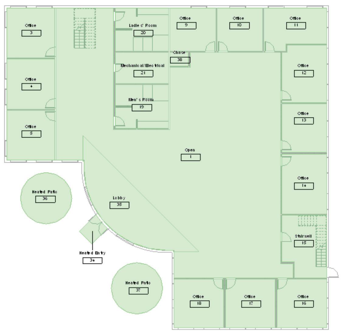
used for different purposes. Spaces are exclusively used for the MEP disciplines for analysis of MEP Systems and can be grouped together to create HVAC Zones.
I am sure most, if not all, know that rooms are phase specific, so when it comes to Renovation projects, those existing rooms need to be defined in the existing phase as well. If the project has Units in say a multi-family or hospitality type project, we
augi.com/augiworld April 2024 | AUGIWORLD Magazine 25 Revit MEP
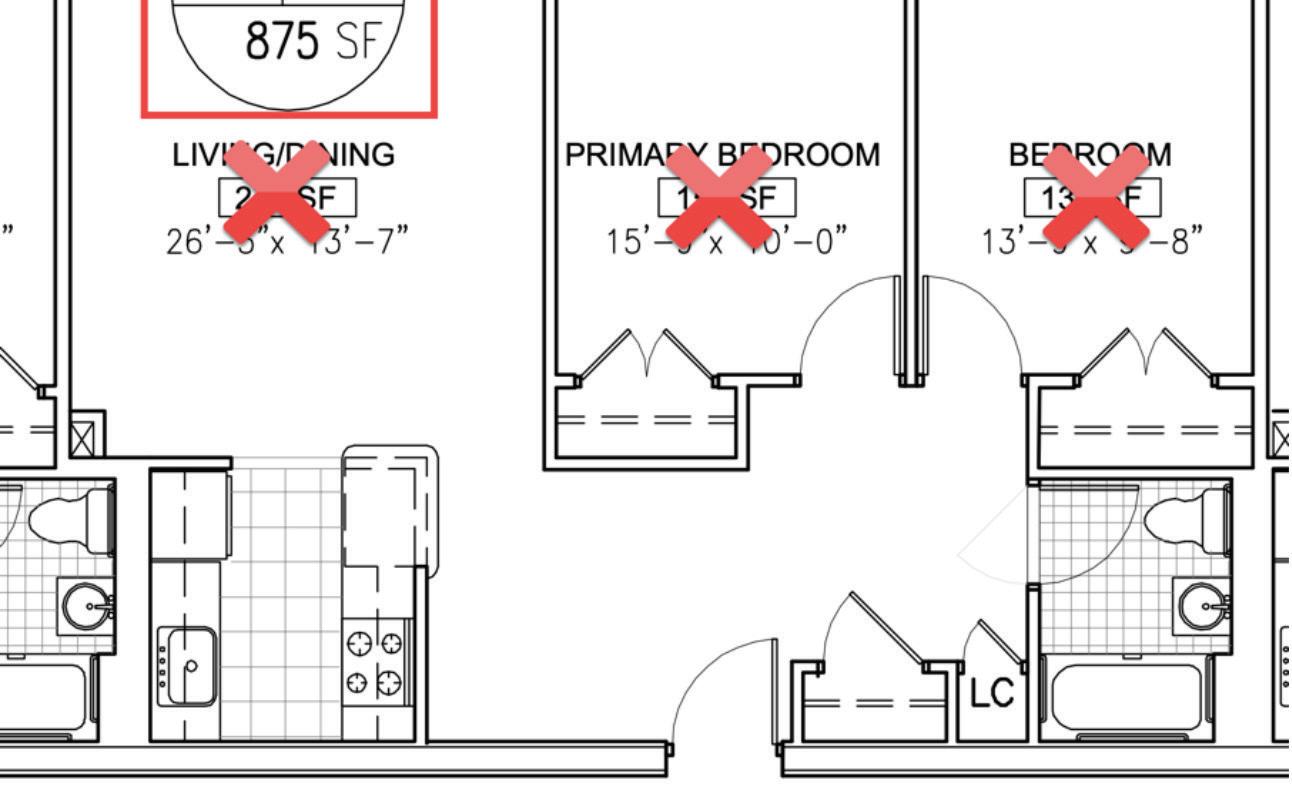
really do not need to know where the kitchen or bathroom is, we just need to know the name of the unit.
I recently started using the Room Name/Number in my space tags, so they automatically update instead of manually using the space naming utility.
Structural Information
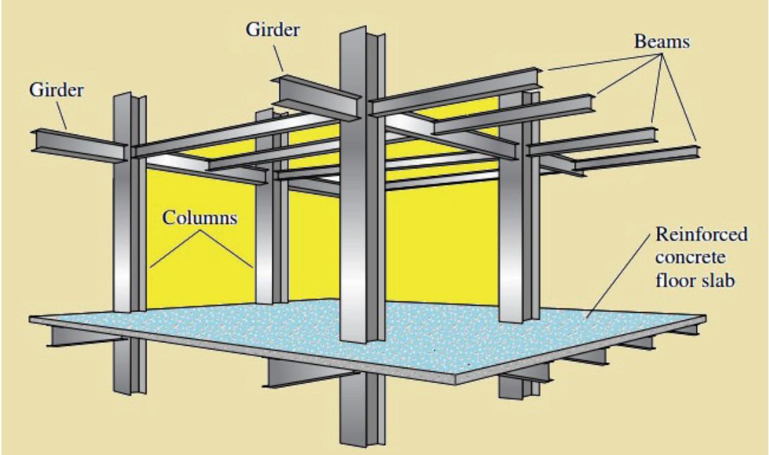
If there are no structural models, the architectural model should include information on the structural components of the building, including any structural beams or columns that may impact the design of MEP systems. You know, typical things we cannot run our duct, pipe, conduit or cable tray through.
Communicate, Communicate, Communicate
We cannot stress enough for the need of better on-going communication. Any changes to your model that will affect our design should be communicated. Please do not assume we will see those changes if we are not looking for them.
DECISIONS THAT AFFECT US!
Changes can, especially those without proper communication, can have a huge ripple effect to what we do or have done.

Hosting
I am not here to debate hosted vs non-hosted. They each have their pros and cons, but I am firmly in the Hosted camp. Most of our MEPF families are face hosted and we need a host to exist in the Architectural model. If ceilings are present, we need those before placing our ceiling mounted families Lighting Fixtures or Air Terminals. Sure, we can use Ref Planes, but moving them from the Ref plane to the ceiling when they are modelled is quite the chore. Because of that, we typically wait until they are modelled, which could be quite late in the design process.
As a BIM Manager, I want to know when something needs my attention, whether that is an orphaned family, or something needs coordination review.
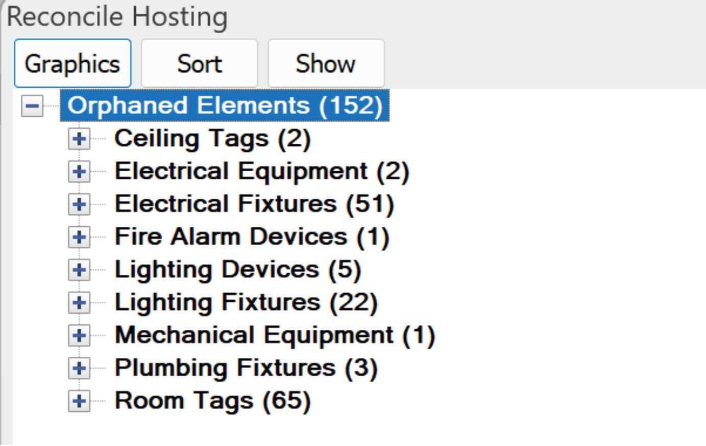
Orphaned elements are way better than deleted elements like from the pre 2012 versions of Revit MEP. We ask that you minimize the deletion of your walls or ceilings so you can redo them using a different type. We would prefer that you modify them or change their type so that their GUID does not change which is what causes our families to be orphaned.
AUGIWORLD Magazine | April 2024 augi.com 26
Revit MEP
Something that can affect our hosted elements is when the position/orientation of your model changes. I am dealing with a project now that is halfway through design and the Civil team, and the client decided to change the rotation of the building on the site as well as move several of the outbuildings. The architect wants to continue as if nothing has changed but our MEP Site plan will be completely incorrect and will need some major workarounds to “look” correct. On the flip side of that, if a model changes its orientation, elevation or position on the site and that is not communicated, it can have adverse effects on our models. A change in the PBP or SP can be an easy change before their model is updated bit not so much with live linking though.
Copy/Monitored Elements
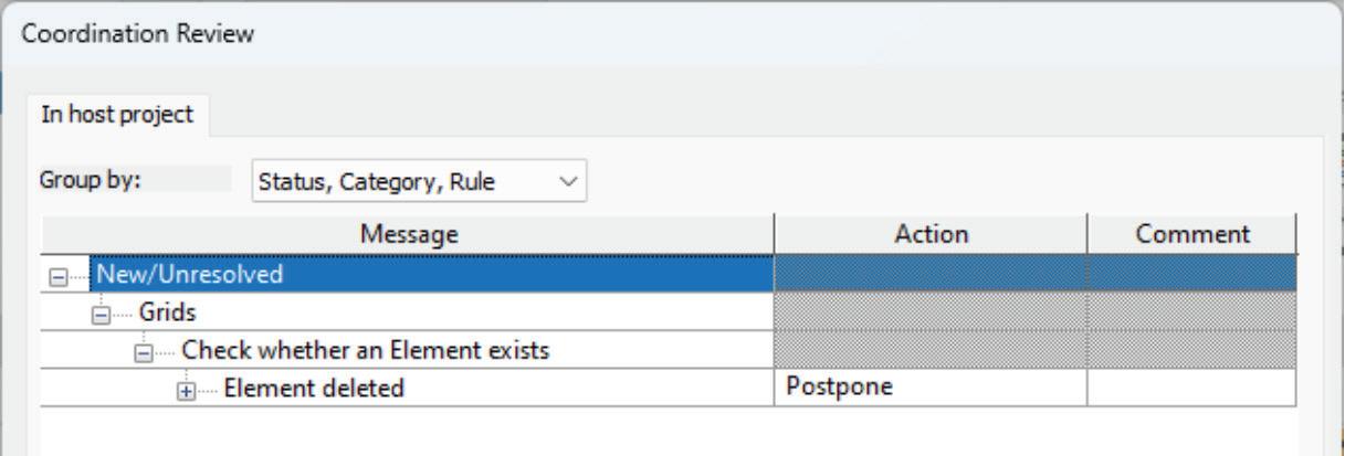
When grids change, sometimes it can be easy and other times it is so painfully time consuming that it is better to just delete them all and copy them again when it comes to renumbering them. In doing so could affect other things like any offset grid heads that are no longer offset when recopied.
Hopefully levels are set when MEP starts their design. Changing a few inches or feet here and there, while can cause ducts or pipes to move up into each other is not that detrimental. However, moving levels several hundred or thousand feet without prior knowledge can break MEP systems.
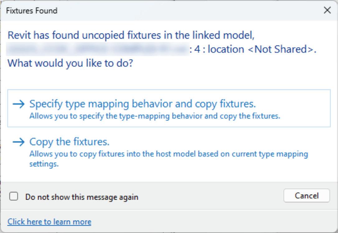
While we can copy/monitor things like Lighting Fixtures and Plumbing Fixtures into our models, they more than likely do not have the necessary parameters for our schedules, tags or match our company standards. We can copy and replace with our own families but that only works if your families and our families have the same origin point.
Phases and Phase Filters
How many of you deviate from the Phases and Phase Filters that Revit provides?
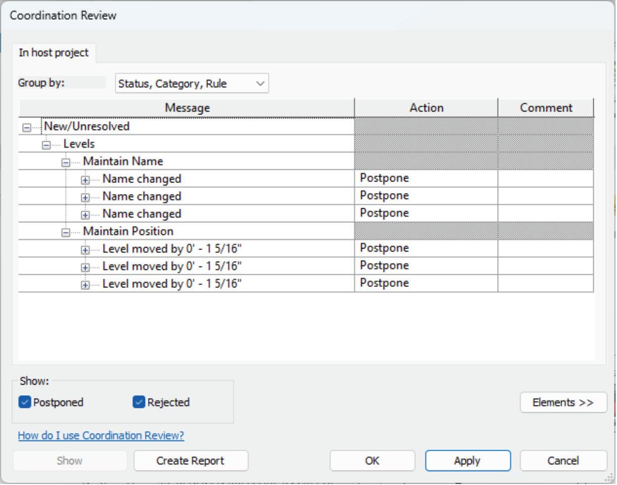
Going back to a BIM Execution Plan or at least the Project Kick-off meeting, a simple list of what you are using would go a long way with consultants to be able to know that up front. When a model is loaded into a project and these do not match, the views will not display things correctly. Each one of those view templates, which at my last firm was about 140, would have had to be edited one at a time to correct that information. Early in my path to BIM Management, I was burned bad when I was creating a few projects where those did not match. I spent so much time changing those in each view template that I now look for that information in my review
augi.com/augiworld April 2024 | AUGIWORLD Magazine 27 Revit MEP
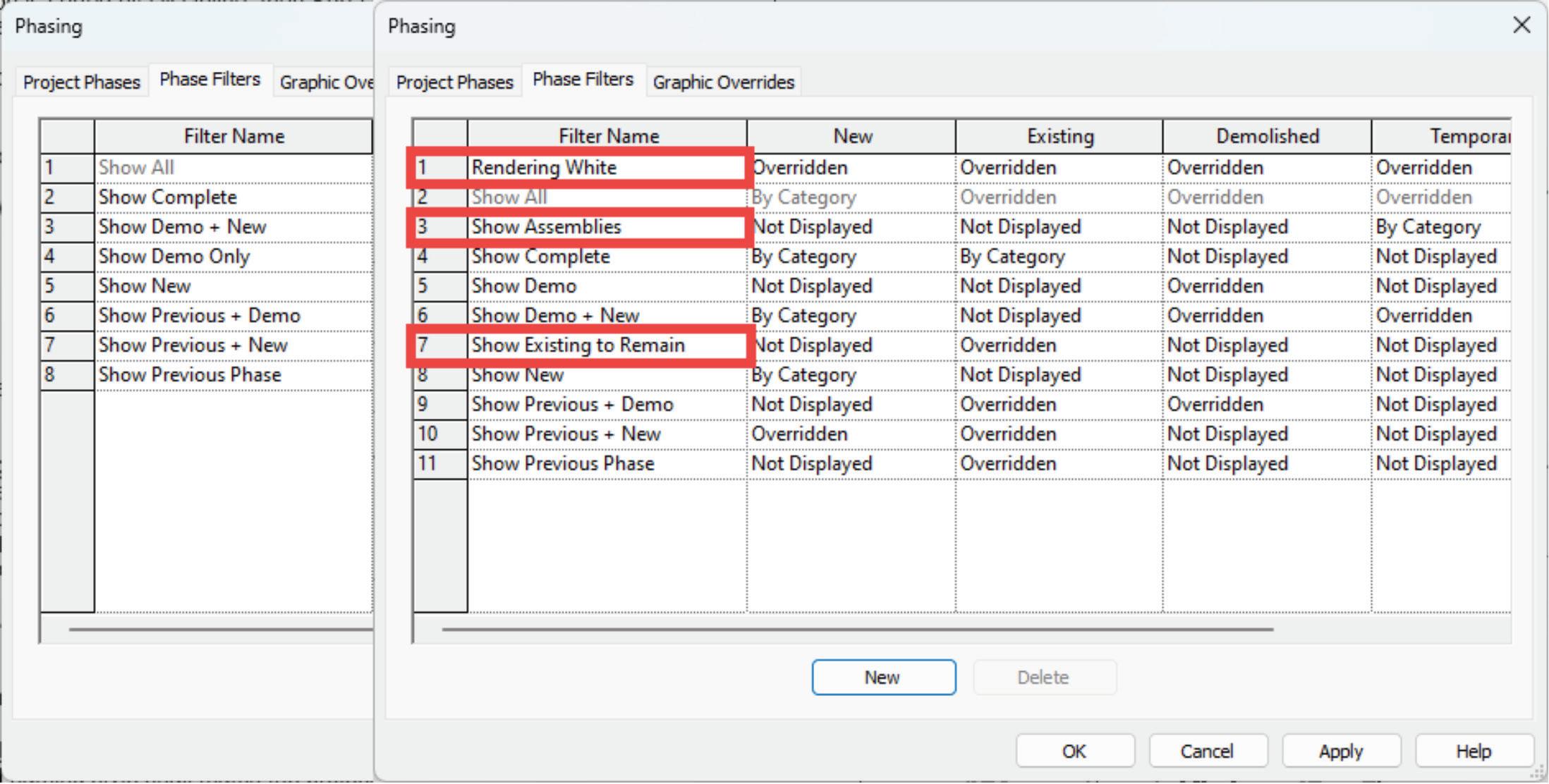
of the Architect’s model before my Project Setup begins.
Furniture
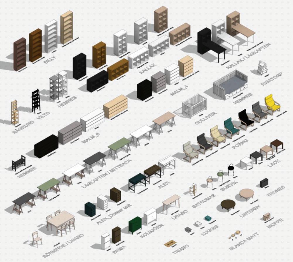
It really does not matter to us whether the furniture is in 3D or 2D, what matters to us is whether we can see it. When it comes to showing furniture on the Lighting RCPs, if furniture is 2D, it stills needs to be elevated so that it fits within our view range. Our RCP view range is set to have a 1’-6” cut plane so that we can see modelled furniture in our RCP views for fixture placement and would need 2D furniture at the same elevation.
Linked Files vs Groups
Aaron Maller is a huge proponent of Groups regardless of project size. He was on an episode of BIM After Dark with The Revit Kid about two years ago discussing the pros and cons of Links and Groups. Go watch it if you have not already.
While I also would prefer the Architect to use Groups. However, if the project is small with just a few links, it is quite manageable but when you get 40+ linked models with 400+ instances of those links, that is not manageable. I worked on a project in Denver several years back where this

AUGIWORLD Magazine | April 2024 augi.com 28 Revit MEP

was the case. It took 20+ minutes to just open the project and doing anything was a waiting game. We asked the Architect to utilize groups, but they refused. We drastically limited our updates to once every 3 months instead of every 2 weeks. When we got a model, I would spend 8-12 hours converting every one of those links to groups, even if they broke. I would get casework at the wrong elevation, duplicates of things, et cetera, et cetera, but the result allowed us to finish the project within our deadlines. With that said the sheer quantity of links and their instances matter for MEP models when those models need to be attached so we are not manually linking all those models and their instances.
Last Minute Architectural Changes
We all know changes will happen and projects will most likely get Value Engineered. With the Autodesk Construction Cloud platform, a lot of projects use the “Live” linking method and MEP loses all control when it comes to getting Architectural Model changes. Now they just happen.
Architects will continue to work up until a deadline we all have. When changes happen at the last minute, there is no time react, things could be broken, out of place or files could get corrupted because one person does not have those changes.
Bottom line, our MEP engineers, designers or even I as the BIM Manager need to be given ample time to react to any changes that occur during the design process. At a previous firm, our contract stated 7 business from last update but often we were able to accommodate 3 business days. Everyone can easily get burnt out chasing those changes and tight deadlines.
FINAL THOUGHTS
Ultimately, we are all just pieces of a puzzle and if we have all the right pieces, we will create a beautiful and functional building.
Our Buildings Group at Garver just recently attended a group Summit and the last activity of our first day was a team building exercise. Each table received a box with a picture of a project we designed that had puzzle pieces inside. While putting the puzzle together several of the groups found themselves, my table included, forcing the pieces together because they looked almost identical, but a few areas were off. Eventually we got it worked out but if you try to force something, most of the time, it just does not work.
When everything is all said and done, at the end of the day, we truly do this to build relationships with our clients and the satisfaction of designing something meaningful and getting paid is a nice bonus. I work with numerous engineers who are good friends with Architects that they met working on a project together. My kid’s godfather is an old co-worker of mine. Don’t sit at desk behind computer screens, get out there, have face to face meetings during and after work hours to help build those relationships and friendships while strengthening them as well.

Jason Peckovitch is an Autodesk Revit Certified Professional for Mechanical and Electrical Design located in SE Iowa. He is a BIM Manager for Garver’s Buildings Business Unit, specifically MEPF. Garver has more than 50 offices across the United States and more than 1200 employees. His CAD/BIM career spans over 25 years but he didn’t switch to the AEC Industry until 2007 as a Mechanical HVAC Drafter and transitioned into BIM Management shortly after where he has been working since. Jason is also the father of three children, a published photographer, gamer, and car/ tech guy. He can be reached at jmpeckovitch@garverusa.com.
augi.com/augiworld April 2024 | AUGIWORLD Magazine 29 Revit MEP
Free Samples–The Spring Edition

SPRING CLEANING
Spring!!! This is the time when snow starts to melt, daylight lasts longer, everything starts to grow and come back to life. This is also when the popular phrase “Spring Cleaning” comes to mind. Now is the time to dive into those closets, find clothes you no longer wear or shoes that no longer fit and have a yard sale. Or dig through your garage, discover all those items you no longer need or want and just throw them out. After all, you do need to make room so you can get more new stuff!!!
FREE STUFF
Well, this is also a great time to open up and dig through the AutoCAD program folder looking for all the free stuff that comes with the program. Last year I started this new series called Free Samples. In these articles I review the many open source lisp programs that come packaged with AutoCAD free for the taking. This time I’m going to continue the Free Samples series by focusing on four opensource lisp routines that were introduced with AutoCAD R12. This was the release when AutoCAD introduced customizable dialog boxes with the use of dialog control language (dcl) making user
AUGIWORLD Magazine | April 2024 augi.com 30 by: Paul Li LISP Commands
input dramatically easier than before. Like my previous Free Samples articles, I’ll introduce the lisp command, explain what it does and discuss what came of it as AutoCAD continues to develop after another 12 releases to the current version.
1. APPLOAD
In 1992 when Microsoft’s Disk Operating System (DOS) was still king and only a single program ran effectively at a time, it was quite a challenge to look for and correctly type in a filename to successfully load an add-in into AutoCAD. There was no option to open another program like Windows Explorer to drag and drop the add-in file into the AutoCAD drawing window for loading. So, AutoCAD R12 came with a new lisp and dcl function called Appload (see Figure 1).
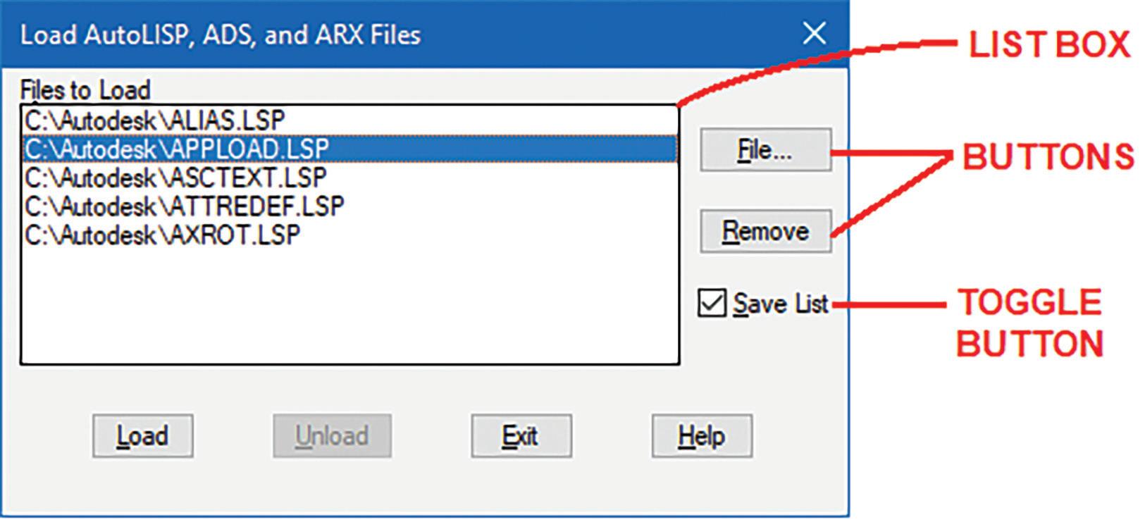
The Appload command opens a custom dialog box titled “Load AutoLISP, ADS and ARX Files.” The dcl code implements the following:
1. List Box – showing files previously selected for loading
2. Buttons – to select more files to Load/Unload or Remove current files from the list
3. Toggle Button – that saves changes made to the current list
This was a tremendous time saver for users who needed a simple but effective way to selectively load add-ins while working in AutoCAD.
Unfortunately, the free open source Appload lisp and dcl files were short lived. They were only included in two more AutoCAD releases (R13 & R14). By the time AutoCAD 2000 came out Autodesk chose to compile the Appload code into a single AutoCAD Runtime Extention (arx) file. The newly compiled Appload.arx file now offers a lot more features and functions (see Figure 2).
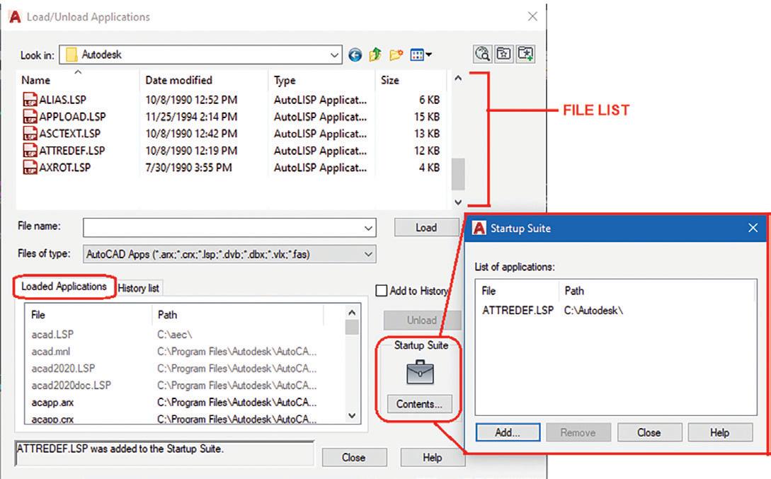
The more powerful Appload command now presents a window titled “Load/Unload Applications” that combines a File List on top with a columned style List Box showing add-ins that have been loaded on the bottom. In addition, there’s a Startup Suite Contents button that launches a separate window to add files to automatically load each time a drawing session opens. Appload.arx has been so effective with these added features that it has continued to accompany AutoCAD releases since 2000 to the current AutoCAD version today.
2. DDMODIFY
AutoCAD’s LIST command back in the DOS days was used quite often to get property information on an object drawn. With this command users can see the object’s Type, Layer, Color, Linetype and etc. (see Figure 3).
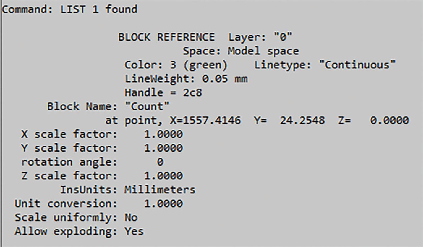
But unfortunately, there wasn’t an option to make any changes to the listed properties. This once again prompted Autodesk to add this needed feature into AutoCAD R12. With the
augi.com/augiworld April 2024 | AUGIWORLD Magazine 31 LISP Commands
Figure 1
Figure 3
Figure 2

implementation of lisp and dcl AutoCAD R12 came with a newly added function called DDModify (see Figure 4)
Similar to the LIST command, DDModify retrieves the properties of an object (Type, Layer, Color, Linetype and etc.) and displays them in a custom dialog box. With the click of a Button additional options are displayed for changes. Also Edit Boxes are implemented to show the current value for modification.
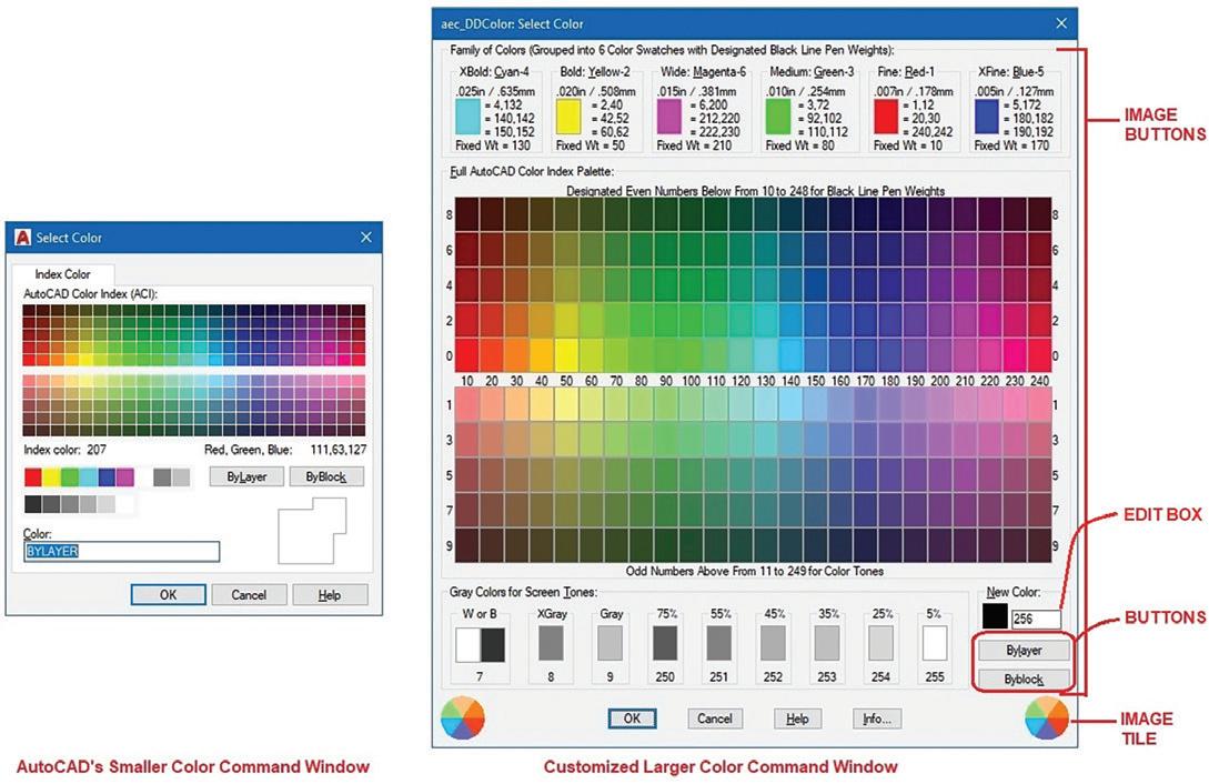
But one of the drawbacks of DDModify was that it did not offer the option to display Attributes within Blocks for modification. So, I decided to create a new function (based on DDModify’s lisp and dcl code) called DDAttMod. This command is included in my free TextApps add-in and can be downloaded from the Autodesk App Store (see Figure 5).
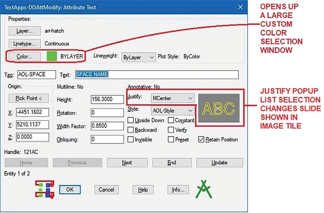
In addition to implementing Buttons, Toggle Buttons and Edit Boxes I included with DDAttMod an Image Tile to display a preview of the Attribute’s Justification. Also, since AutoCAD’s Color selection window was just way too small, I used lisp and dcl code to generate a larger Color selection window with the use of Image Buttons (see Figure 6).
Like Appload, DDModify lisp and dcl files continued to ship with AutoCAD for two more releases (R13 & R14). Then AutoCAD 2000 came out implementing the new “Heads-Up Design Environment” and “Improved Access and Usability”. Unlike the
AUGIWORLD Magazine | April 2024 augi.com 32 LISP Commands
Figure 5
Figure 6
Figure 7
Figure 4
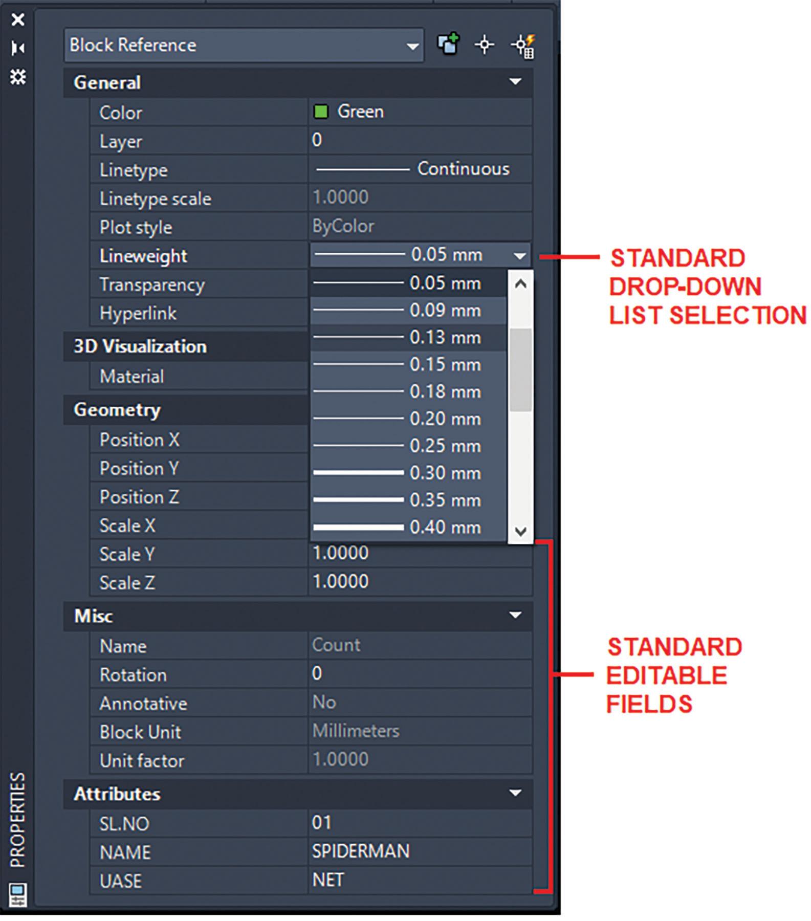
previous dcl custom dialog boxes, the new and improved graphics user interface offered both floating and docked windows. AutoCAD used this new feature to replace the DDModify command with the new Properties command. The Properties command opens up a window that can float or dock showing items that can be changed with the use of Drop-down Lists or Editable Fields (see Figure 7).
Though the DDModify code still can be loaded and run successfully even in the current version of AutoCAD, there’s been no updates to include the many improvements added since AutoCAD R14. Also, once you become accustomed to using the Properties window, there’s little incentive to go back to using the DDModify command. For backwards compatibility, AutoCAD since release 2000 has included an alias in the acad.pgp file so that when DDModify is entered the Properties window appears.
3. DDOSNAP
AutoCAD introduced object snaps back in version 2.0. When used properly, object snaps are one of the major features that gives the AutoCAD user accuracy throughout the entire drawing process. Different object Types possess their own object snap settings. This makes it possible for you to locate and position objects exactly where you want
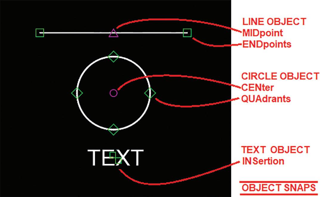
them to be. For example, note the LINE, CIRCLE and TEXT object snap modes (see Figure 8):
• LINE objects contain two object snap modes:
• ENDpoint – this is located at each end of the LINE segment
MIDpoint – this is located in the middle between the two end points
9
CIRCLE objects contain the following two object snap modes:
• CENter – this is located at the center of the CIRCLE
• QUAdrant – this is located on the CIRCLE at the following angles: 0⁰, 90⁰, 180⁰ and 270⁰
• TEXT objects contain only one object snap mode:
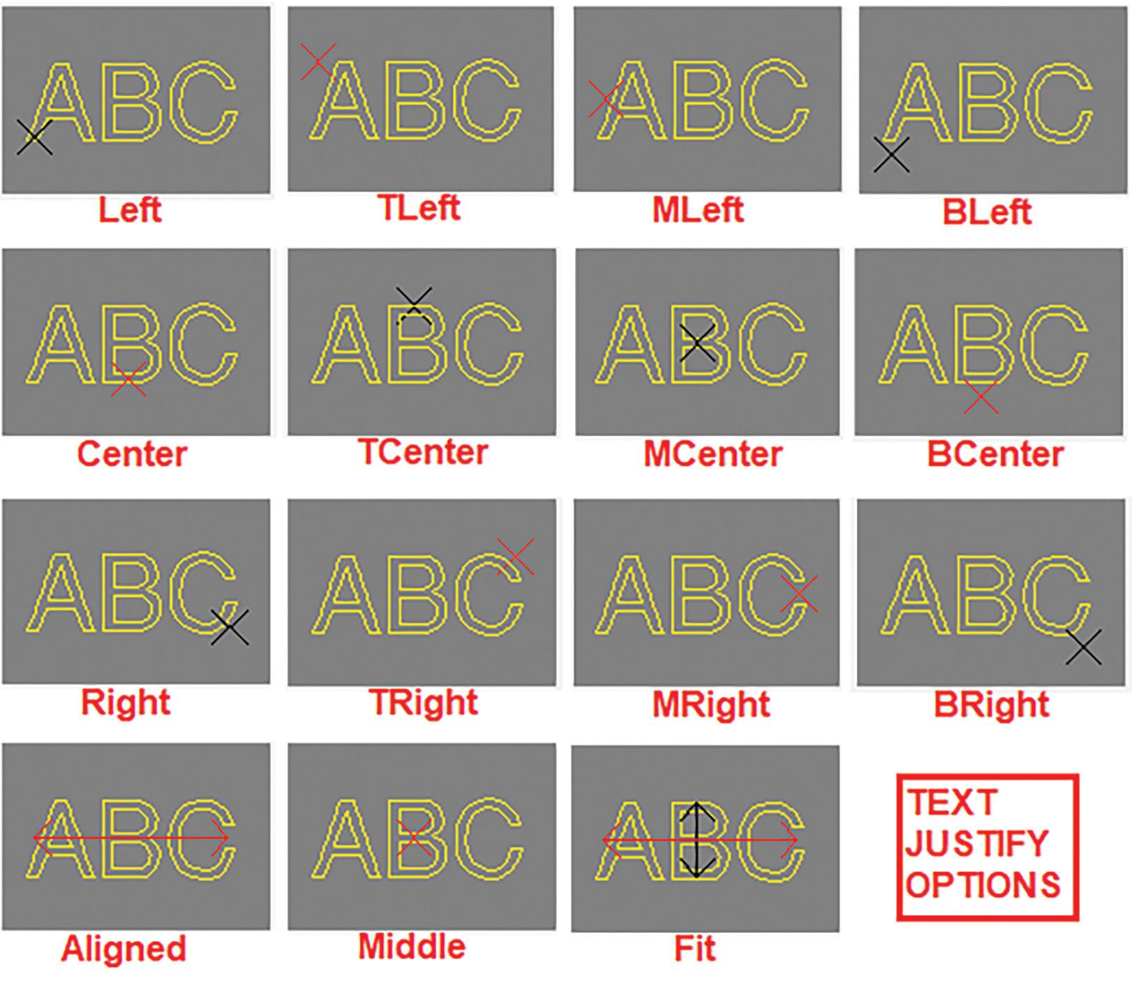
• INSertion – this is also known as the TEXT’S Justification location (see Figure 9)
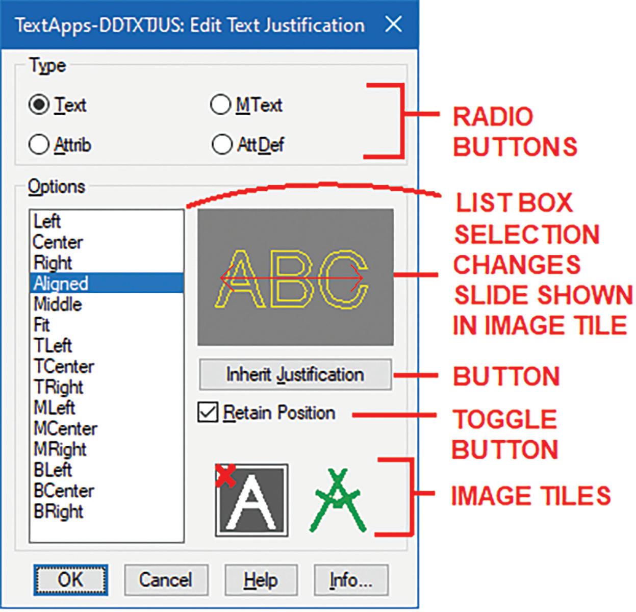
As you can see though TEXT only has one object snap setting, there are a number of locations where
10
augi.com/augiworld April 2024 | AUGIWORLD Magazine 33 LISP Commands
Figure 8
Figure
Figure
LISP Commands
this can occur on the object. Since there are so many TEXT justification options and I really wanted to get a visual of where they’re located, I created a command packaged as part of TextApps I call DDTxtJus. Similar to DDAttMod, DDTxtJus is a lisp function that uses dcl to create a custom dialog box to show the various TEXT justification options in a List Box. The selected option automatically changes the picture shown in the Image Tile giving the user a preview of where the INSertion position is located (see Figure 10).
The INSertion object snap setting also applies to BLOCK objects and there is one more object related object snap setting called NODe which applies to POINT objects. The rest are geometry related object snap settings: INTersection, PERpendicular and TANgent.
Note: I would avoid the use of the NEArest object snap setting because you can end up with inaccurate drawings where objects are placed close but not exactly where they should be.
All these object snap settings can be entered at the command prompt in the middle of drawing or editing commands. Or with the use of the OSNAP command permanent object snaps can be set for the entire drawing session (a.k.a. “running object snaps”). Furthermore, object snap settings can be combined together by entering them at the command prompt separating each with a comma. For example, to set ENDpoint, MIDpoint, CENter and INTersection as running object snaps, the following is entered at the command line:
Command: Osnap
Enter list of object snap modes: END,MID,CEN,INT
Notice that only uppercase letters are required to be entered. But what if you changed your mind and now want to include TANgent. You would have to enter the entire list again before adding the new TANgent object snap. Likewise, if you want to remove an object snap setting from the list, you will have to again re-enter all the object snap settings you want to keep. On top of all that the object snap settings even the shorter uppercase letters need to be entered and spelled correctly otherwise AutoCAD will reject the entry.
All of these drawbacks prompted Autodesk to
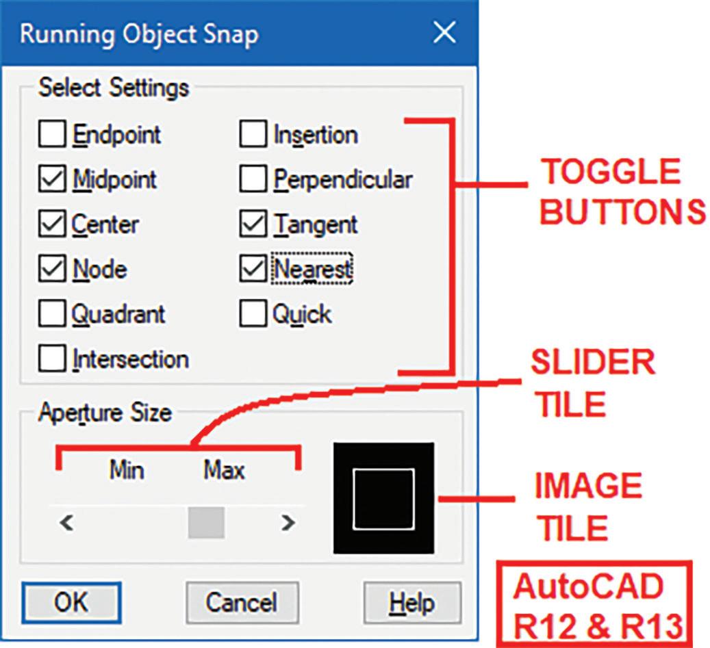
introduce with AutoCAD R12 the new lisp combined with dcl command called DDOsnap (see Figure 11).
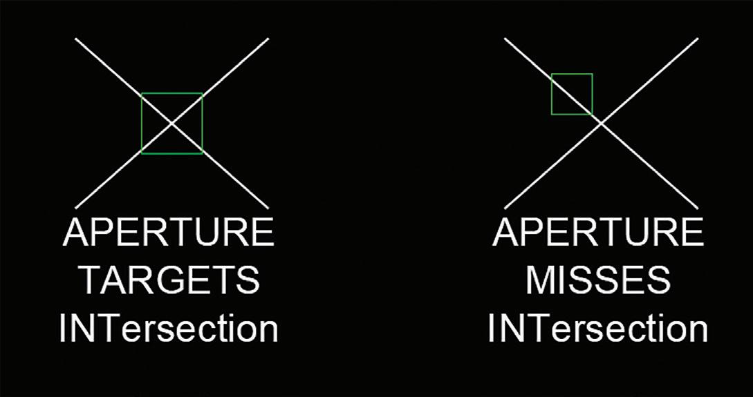
DDOsnap opens a custom dialog titled “Running Object Snap” and effectively implements Toggle Button combinations to select and unselect running object snap settings. In addition, at the bottom of the dialog box was an option using an Image Tile and a Slider Tile to adjust a related drawing tool called the Aperture Size. The Aperture setting (ranges from 1 to 50 pixels) changes the “Target” crosshairs size affecting the area and location where object snap settings are scanned. So, an Aperture setting of 1 would result in a very small area where the crosshairs are scanned. On the other hand, an Aperture setting of 50 would result in a much larger crosshairs area to be scanned during the object snap selection process (see Figure 12).
Unlike Appload and DDModify, the DDOsnap lisp and dcl files were kept for only one more AutoCAD
AUGIWORLD Magazine | April 2024 augi.com 34
Figure 11
Figure 12

release (R13). AutoCAD R14 introduced a built-in DDOsnap command that displayed a custom Osnap Settings dialog box with the introduction of Tabs. Also added is a Clear All Button and a Slider Tile with a brand-new look (see Figure 13).
This was also short lived because AutoCAD 2000 completely revamped the DDOsnap command yet again. The command is now replaced by just entering the Osnap command or the DSettings command. The newer graphics user interface would now display the Drafting Settings window (see

Figure 14).
In addition to adding a couple more Toggle object snap settings a Select All Button is now clustered with the Clear All Button at the upper right corner
NOTICE THAT ONLY UPPERCASE LETTERS ARE REQUIRED TO BE ENTERED. BUT WHAT IF YOU CHANGED YOUR MIND AND NOW WANT TO INCLUDE TANGENT. YOU WOULD HAVE TO ENTER THE ENTIRE LIST AGAIN BEFORE ADDING THE NEW TANGENT OBJECT SNAP.
of the window. The Aperture Size setting at the bottom is completely dropped. Instead, a separate Options Button is added at the lower left corner to call up the Drafting Tab to make Aperture Size and other drawing environment changes. Lastly, to invoke the original command line version of Osnap the command would need to be preceded with a dash:
Command: -Osnap
So, having gotten used to running the DDOsnap command for three AutoCAD releases (R12, R13 & R14) and for the sake of backwards compatibility like with DDModify, the current AutoCAD release

augi.com/augiworld April 2024 | AUGIWORLD Magazine 35 LISP Commands
Figure 14
Figure 15
Figure 13
still continues to support the DDOsnap command. AutoCAD’s acad.pgp file includes an alias that calls up the Drafting Settings window which now shows even more Tabs and object snap settings (see Figure 15).
4. DDVPOINT
Starting with release 2.18 AutoCAD slowly began the introduction of offering not only 2 dimensional (2D) but also 3 dimensional (3D) drafting tools. During this small step forward, most objects can be given a thickness but with no top or bottom surfaces. Only the Solid (2D) object Type when given a thickness would have surfaces on all six sides. All objects could be positioned in a different elevation other than the zero-elevation plane. For setting up 3D views AutoCAD added the new VPOINT command. The Vpoint command gives the user the option to respond with X,Y,Z coordinates rotating on the 2D (X,Y axis) plane and upward to look from a 3D (Z axis) direction. But the Vpoint coordinate entry process was quite cumbersome. You would have to remember the X,Y,Z coordinate entry sequence precisely in order to achieve the desired view or rely on selecting these coordinates from the AutoCAD on screen menu (see Figure 16).
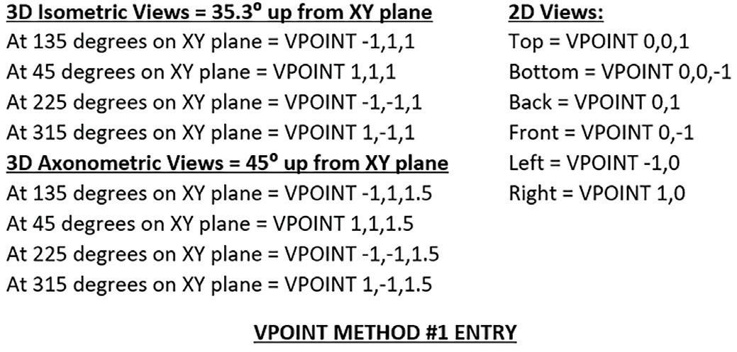

Since both of these Vpoint command entry methods have their drawbacks, AutoCAD R12 introduced the highly needed lisp and dcl command DDVPOINT. The DDVpoint command uses the third VPoint entry method which is based on the Rotation angle on and from the X,Y plane. DDVpoint’s custom dialog box displays a simple and yet very effective Vpoint Rotation angles selection process (see Figure 18).
A second method to respond to the Vpoint command instead of entering X,Y,Z coordinates is to hit the Enter key on the keyboard. This would make all the objects temporarily on the graphics drawing area disappear and allow you to freely rotate around the X,Y,Z axis using this tripod symbol as a navigational device (see Figure 17).
But this method of setting a 3D view with the Vpoint command lacked control. Also, the view is set blindly since no objects are displayed on the screen but the tripod symbol.

AUGIWORLD Magazine | April 2024 augi.com 36
LISP Commands
Figure 16
Figure 17
Figure 18
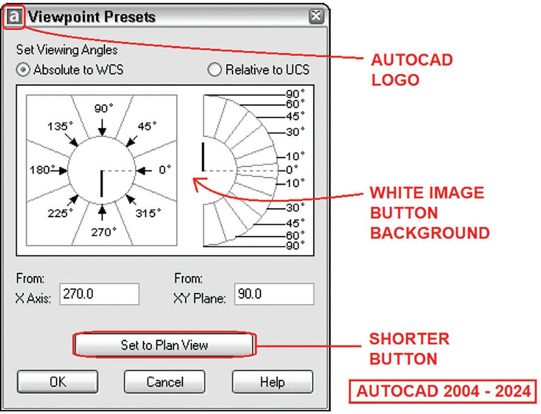
At the center of the “Viewpoint Presets” dialog box is a large Image Button that’s basically divided into two sections. The left section shows an image for selecting the Rotation angle on the X,Y plane. Clicking on any of the angles labelled around the outside of the circle would return the angle matching those numbers. Clicking on areas inside the circle would return an angle that is an extrapolation of the angles in between. Similarly, the right section shows an image for selecting the angle above and below the X,Y plane. Clicking on the area between the trapezoidal shapes would return the matching labelled angle. Clicking on the area inside the inner arc would result in an extrapolation of the angles in between.
The DDVpoint custom command provided a very effective frontend graphic user interface solution to setting 3D views. The lisp and dcl files continued to be shipped with AutoCAD for five more releases (R13, R14, 2000, 2000i & 2002). Finally, AutoCAD 2004 incorporated DDVpoint as part of the built-in native AutoCAD command dropping the need for the custom DDVpoint lisp and dcl files (see Figure 19).
Autodesk purposely designed the dialog box to display the same look and feel as the previous custom DDVpoint command. The major differences are:
1. Addition of the AutoCAD logo on the title bar
2. White background to the Image Button
3. Shorter Set to Plan View Button at the bottom
Like with the Osnap command eventually the

Vpoint command took the place of displaying the dialog box. To invoke the command line version this required a dash to precede the command:
Command: -Vpoint
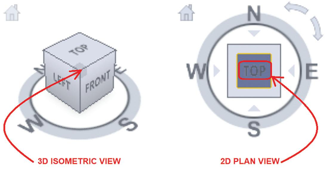
But the effectiveness of the Vpoint command quickly faded with AutoCAD 2009’s introduction of the ViewCube. This resizable icon can be positioned in any one of the four corners of the graphics drawing area. The ViewCube could be easily toggled on or off by invoking the command NAVCUBE. Clicking on any part of the ViewCube would change the view on the screen to match (see Figure 20).
20
augi.com/augiworld April 2024 | AUGIWORLD Magazine 37 LISP Commands
Figure 19
Figure

Since all six surfaces of the ViewCube are labeled with TOP, BOTTOM, FRONT, BACK, LEFT and RIGHT, clicking on a surface would immediately set that as the 2D view. Clicking on any of the corners would change the view to a 3D isometric view. Now setting the desired view can easily be done without the need to temporarily hide drawn objects and you won’t have to deal with dialog boxes obstructing the graphics drawing area.
From 2.18 to now after many releases later AutoCAD has clearly developed into a fully functional 3D design program. Throughout this growth process, AutoCAD has introduced many powerful tools to assist the user in setting up the 3D environment. But like Osnap, the traditional Vpoint command continues to be available to execute in AutoCAD. Also, DDModify and DDOsnap AutoCAD’s acad.pgp file has kept an entry for DDVpoint to invoke the Vpoint dialog box.
SPRING INTO ACTION
So, each of the four lisp and dcl custom commands released with AutoCAD R12 had their own unique though sometimes similar developmental cycles. I’ve placed in a table summarizing the process (see Figure 21).
Hopefully I’ve again piqued your interest on the many free sample lisp files available from previous up to the current version of AutoCAD. At the time this article is published, the next AutoCAD has either already been released or is just about to come out. After installation, this is the perfect time to crack open the AutoCAD 2025 program folder.
Instead of “Spring Cleaning” let’s “Spring into Action” and eagerly go through all the free sample lisp files that are now waiting to be discovered in the new AutoCAD 2025.

Mr. Paul Li graduated in 1988 from the University of Southern California with a Bachelor of Architecture degree. He worked in the Architectural field for small to midsize global firms for over 33 years. Throughout his tenure in Architecture he has mastered the use and customization of AutoCAD. Using AutoLISP/ Visual Lisp combined with Dialog Control Language (DCL) programming he has developed a number of Apps that enhance the effectiveness of AutoCAD in his profession. All the Apps actually came out of meeting challenging needs that occurred while he worked in the various offices. He has made all the Apps available for free and can be downloaded from the Autodesk App Store. Though he recently retired from the Architectural profession, Paul continues to write articles depicting his past work experience. Some of these articles can be found in AUGIWorld Magazine where he shares his knowledge learned. Paul can be reached for comments or questions at PaulLi_apa@hotmail.com.
AUGIWORLD Magazine | April 2024 augi.com 38 LISP Commands
Figure 21
TTH Toolset: Enhancing Productivity in Pipe Networks and Sheet Set Management

OVERVIEW
The TTH toolset boasts a collection of powerful productivity tools designed for both Pipe Networks and the Sheet Set Manager. Having personally experienced the benefits of this toolset, I highly recommend exploring its capabilities. In this article, I will highlight a few key tools within the set, encouraging you to try them out for yourself. Keep in mind that there is a free trial available, with a cost associated after its expiration.
PIPE SLOPE/ELEV
One standout tool in the TTH set is the Pipe Slope/ Elev tool. This feature facilitates swift edits between structures, offering additional functionalities such as the ability to add a drop between structures and
maintain a constant slope throughout the pipe run. This tool streamlines the editing process, making it more efficient and user-friendly.
SHEET SET PUBLISHER AND PROPERTY EDITOR
Another noteworthy inclusion in the TTH toolset is the Sheet Set Publisher and Property Editor. This tool provides a convenient platform for quick edits, resembling an Excel-like format. What sets it apart is the ability to seamlessly copy data into an Excel sheet, make edits, and then paste the modified information back into the editing window. This feature enhances flexibility and ease of use, allowing users to leverage the familiarity of Excel for efficient data manipulation.
Steps to download:
https://apps.autodesk.com/en
1. Sign-in into your Autodesk account
2.
3. Download custom installer

augi.com/augiworld April 2024 | AUGIWORLD Magazine 39
Inside Track by: Marco Oregon
Search DA Pipe Network Toolset
us for
news
Please let us know if you have some news to share with
future issues. Likewise, we want to know if you are a featured product or
item user and would like to write a review. We’d love to hear from you!





AUGIWORLD Print AUGI HotNews Digital Visit www.AUGI.com/advertise Connect with AUGI Members Increase your revenue by advertising with AUGI and reaching its 400,000 Members. AUGI.com Website Thousands of visits per month Forum Advertising Active membership participation • Advertising Email Blasts • Targeted Mailings • Industry Leading Google Results Site US $8.00 The Official Publication of the AUGI Design Community Diamond Sponsors Implementing Best Strategies Automating Punch Lists with Bluebeam Revu Setting Up System Variables for Success in AutoCAD AUGIWORLD Also in this issue:


