Subsea tooling catalogue

Specialist subsea tooling and equipment within our mechanical solutions service line ashtead-technology.com
For details on our full equipment fleet, visit ashtead-technology.com
What we do
Through our three service lines – survey & robotics, mechanical solutions and asset integrity – we support the installation, IMR and decommissioning of offshore energy infrastructure.
offshore Technology, Overview


leading
What we do
Through our three service lines – survey & robotics, mechanical solutions and asset integrity – we support the installation, IMR and decommissioning of offshore energy infrastructure.
Overview
What we do

Through our three service lines – survey & robotics, mechanical solutions and asset integrity – we support the installation, IMR and decommissioning of offshore energy infrastructure.

Support services
We provide offshore deployment services carried out by our highly-skilled and experienced personnel. We also provide an asset management service for equipment repair, maintenance and storage to ensure the operational readiness of our customers’ assets.
Extensive tooling fleet
Ashtead Technology offers the broadest and most advanced range of subsea rental equipment from leading manufacturers. Leveraging our in-house engineering capability, we also specialise in a wide range of in-house designed equipment.
Overview
ashtead-technology.com Key Contacts
01 Valve manipulation tools & accessories 02 Dredging & jetting 03 Cutters & grinders 04 Subsea pumping & injection 05 Topside pumps 06 Cleaning tools 07 Manipulators 08 Hydraulic power units & reelers 09 Sampling tools 10 Intervention skids 11 Grabs 12 Bags, mattresses & baskets 13 Miscellaneous ROV tools 14 Camera boom arms inspection camera’s 15 ACE Winches Lifting, pulling and deployment contents Looking for a bespoke solution or something not featured in this catalogue? Visit our website: www.ashtead-technology.com
Our international team of experts are ready to support you
Section 1
Valve manipulation tools & accessories 02 Dredging & jetting 03 Cutters & grinders
Subsea pumping & injection 05 Topside pumps 01
01
04
Valve manipulation tools & accessories
Applications
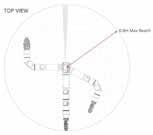
7-function (or custom fit)
Highly modular & configurable
450m depth rating
10kg full reach lift
In-build kinematics
Master arm controlled
Features
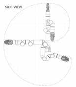
Ready-built and designed for industry leading inspection class vehicles
All-electric, zero oil
End effectors: grabbers, probe handlers, cutters (or BYO)
Advanced software interface with 3D visualisation
One-click deploy/stow position
Adjustable grab force

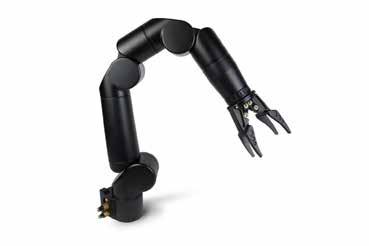
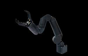
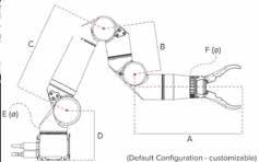
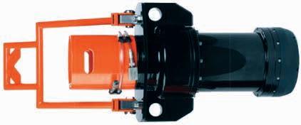
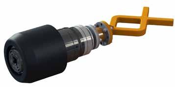
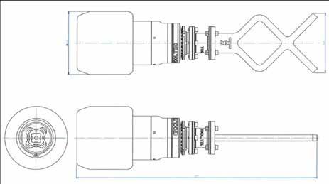
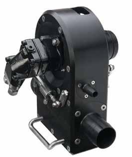
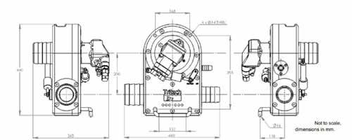
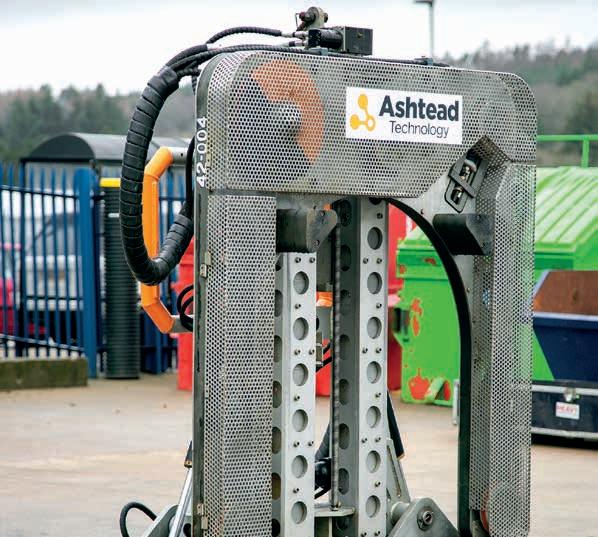
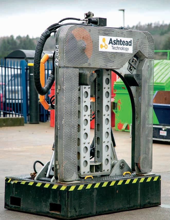
Reach Robotics Bravo 7 Arm
A tough, 7-function manipulator for inspection class vehicles
The Bravo 7 is a 7-function manipulator that opens up new compact inspection and intervention opportunities for service providers, researchers, and other operators. Designed to conduct tasks usually reserved for human drivers, the arm's dexterity and responsiveness pave the way for advanced applications. The form factor was specifically designed for industry leading inspection-class ROVs making it ready-to-go option for existing fleets.
Reach Robotics Bravo 7 Arm
Specifi cations
Joint
End-effector accuracy
Grabber close force
Optional sensor interface
Control modes
Power interface
Bulkhead
Pigtail
Comms interface
Bulkhead
Pigtail
<10mm
80kg (800N)
PWR + 485 + Ethernet
Position, velocity, cartesian (XYZ)
MCBH4M - MC 4C male
MCIL4F - MC inline, 4C female, 60cm
MCBH8ME - MC Ethernet, 8C male
MC Ethernet inline, 8C female 100cm

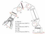
20-48V Voltage Nominal power Peak power Electrical 200W 300W COMS RS232/RS485/Ethernet
Depth Temp Material 450MSW 0°C to 40°C AL7075 T6
Lift capacity Max lift Weight (air) Weight (water) 10kg 20kg 9.5kg 4.5kg Reach Full reach lift
Environmental
Mechanical
speed
force 900mm 10kg 45°/s 10kN
Linear
Applications
Class 1-4 valve operations
Flying lead operations
Features
ISO 13628-8 fig 18 (API 17D)
Class 1-4
Modified client specific interfaces available
Max torque 2,711Nm / 2,000 lbf-ft
Provides torque feedback, output turns count & visual indication of motor turns
In the box
Class 1-4 torque tool
Fish tail handle
Hose set
Operations and maintenance
manuals
All hoses supplied
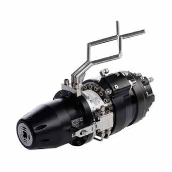
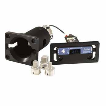
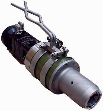
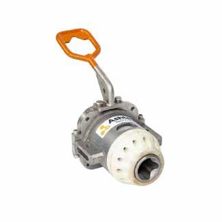
Zetechtics Class 1-4 Torque Tool
500-2,711Nm
class 1-4 torque tool
The Jupiter Subsea Intelligent Torque Tool Class 1-4 Rotary Docking interfaces with subsea production systems and is capable of producing torque up to 2,711Nm (2,000 lbf-ft). The tool can provide torque feedback, turns count, torque range sensing and visual indication of motor turns.
The tool conforms to the ISO 13628-8 fig 18 class 1-4 bucket interface used extensively in the subsea industry for valve overrides operated by ROV.
Zetechtics Class 1-4 Torque
Tool Specifications
Interface
Maximum working torque
Weight in air
Weight in water
Maximum working depth
Maximum motor supply
Maximum latch supply
Recommended hydraulic fluids
Electrical interface
Hydraulic connections
Class 1-4 Rotary docking interfaces to BS EN ISO 13628-8 2006
Low Torque Gear : 500Nm (369 lbf-ft)
High Torque Gear : 2,711Nm (2,000 lb-ft)
47.7kg
37.1kg
3,000m
160bar (2320psi)
210bar (3045psi)
Shell Tellus 22 or 32 Castrol Hyspin AWS 22 or 32
Burton 55 series 1508
CW & CCW: 8 JIC
Latch & unlatch: 4 JIC
High torque: 4 JIC
Motor Case: 4 JIC
Comp: 4 JIC
Applications
Class 1-4 valve operations
Flying lead operations
Features
ISO 13628-8 fig 18 (API 17D) class 1-4
Max torque 2700 Nm / 2000ft lbs
Dual range
Dual sensor electronic turns counter
Internal strain gauge Latching wings
Can be configured for diver use
In the box
Class 1-4 torque tool
Class 1 & 2 socket (11/16” sq)
Class 3 socket (1-1/8” sq)
Class 4 socket (1-1/2” sq)
Fish tail handle
Cage with USD mount (optional)
Hose Set
Low range converter
Operations and maintenance manual
All hoses supplied
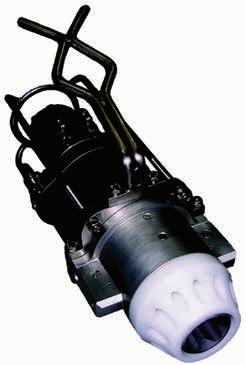
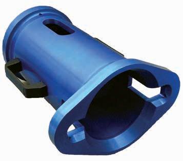
Class 1-4 Torque Tool (API 17D)
100-2700Nm class 1-4 torque tool
This torque tool has been specifically developed to provide the highest level of performance. It has integral torque and turns counting sensors for closed loop control. When matched with a PSS supplied torque tool control manifold, it can provide precise feedback on torque response of any subsea operation. These can alternatively be utilised by connecting a PSSL universal subsea display, which would give a visual read-out of live torque feedback and turns counter.
The tool conforms to the ISO 13628-8 fig 18 class 1-4 bucket interface used extensively in the subsea industry for valve overrides operated by ROV. The tool has latching wings allowing the tool to hold on to the interface. The latching wings are hydraulically driven forward and spring retracted. Thus in the case of a loss of hydraulic power the wings will release. The tool uses a high specification drive motor for consistent torque output characteristics, even if used with direct hydraulic pressure control without the feedback sensor. The motor shares casing oil with the gearbox therefore avoiding the need for a separate compensator.
Note that for applying torques less than 108Nm (80ft lbs) the class 1&2 tool is recomended.
Class 1-4 Torque Tool (API 17D)
Specifications
Torque interface
Torque range
Motor size
Latching strength
Weight in air
Weight in water
Electrical connector
Recommended hydraulic fluids
CW
CCW
Latch
Case Drain
ISO 13628-8 fig 18 class 1-4
540-2700Nm / 400-2000ft lbs (gearbox fitted)
108-540Nm / 80-400ft lbs (direct drive)
236cc
1t at 160bar
34kg / 75lbs
28kg / 62lbs
8 pin mini burton
Shell Tellus 22 or 32 Castrol Hyspin AWS 22 or 32
4 JIC
4 JIC
¼ Swage
4 JIC
Applications
Class 5 valve operations
Features
ISO 13628-8 fig 18 (API 17D) class 5 Max torque 6750Nm / 5000ft lbs
Dual sensor electronic turns counter
In the box
Class 5 Torque Tool
Fish tail handle
All hoses supplied
Operations and maintenance manual
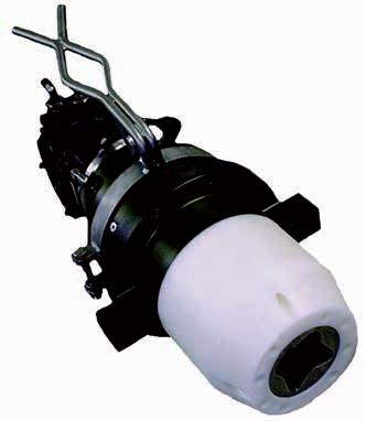
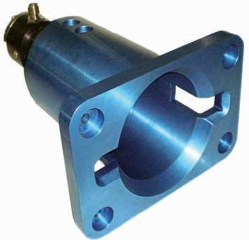
Class 5 Torque Tool (API 17D)
Class 5 valves up to 6,750Nm
This torque tool has been specifically developed to provide the highest level of performance using a high specification motor and robust gearbox in an efficient, low weight assembly. The socket is specially profiled for easy alignment. A range of control accessories is available including a precision surface torque verification unit for pre-dive testing.
The tool conforms to the ISO 13628-8 fig 18 class 5 interface used extensively in the subsea industry for pipeline valve operations by ROV. The tool uses a high specification drive motor for consistent torque output characteristics.
Class 5 Torque Tool (API 17D)
Specifications
Torque interface ISO 13628-8 fig 18 class 5
Maximum torque 6,750Nm / 5,000ft lbs
Torque range 1350-6750Nm / 1000-5000ft lbs
Socket size 2” square
Motor size 315cc
Weight in air 54kg / 119lbs
Weight in water 41kg / 90lbs
Electrical connector 8 pin mini burton
Recommended hydraulic fluids Shell Tellus 22 or 32 Castrol Hyspin AWS 22 or 32
JIC
CCW 4
CW 4
JIC
Applications
Class 6 valve operations
Class 7 valve operations
Features
ISO 13628-8 fig 18 (API 17D) class 6/7
Max torque 17,000Nm / 12,600ft lbs
Dual sensor electronic turns counter
In the box
17kNm Torque Tool Class 6/7
Class 6 socket
Class 7 socket
Fish tail handle
Bladder style compensator Operations and maintenance manual
All hoses supplied
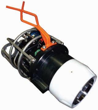
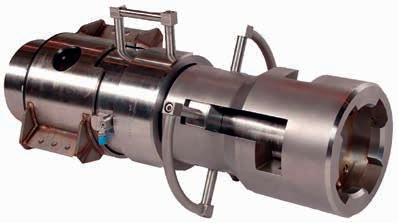
17kNm Torque Tool Class 6/7 (API 17D)
Class 6/7 short nose torque tool
This torque tool has been specifically developed to address the increasing requirement for a 17kNm tool. The interface is based on the ISO 13628-8 fig 18 class 7, with the exception of the length of the nose of the tool, this is based on the industry standard. The tool is supplied with a class 6 socket.
The tool can be supplied with a hot stab receptacle, electronic turns counter and integrated compensator unit, to allow the tool to be deployed to the subssea work site in a basket, separate from the ROV and then connections made with a hot stab.
A socket inset is used to allow class 6 size socket or class 7 size socket valves to be operated.
17kNm Torque Tool Class 6/7 (API 17D)
Specifications
Torque interface
Maximum torque
Socket sizes
Weight in air
Weight in water
Electrical connector
Sensors
Recommended hydraulic fluids
CW
CCW
ISO 13628-8 fig 18 (reduced length)
17,000Nm / 12,600ft lbs
3-1/2” square & 2-5/8” square
74kg / 160lbs
55kg / 120lbs
8 pin mini burton
Dual sensor inductive turns count sensor
Shell Tellus 22 or 32 Castrol Hyspin AWS 22 or 32
4 JIC
4 JIC
Applications
Class 6 / 7 valve operations
Features
ISO 13628-8 class 7
Up to 35,000Nm / 25,814 ft lbs
Class 4 torque tool input
Built in compensator
Two different nose lengths supplied
In the box
Norbar torque wrench
Standard length tool
Class 6 nose cone
Class 6 socket
Short nose conversion
Operation and maintenance manual
Class 4 to Class 6/7 Gearbox Adaptor
Class 6 and 7 valves up to 35,000Nm
Class 7 requires 35,000Nm to achieve this with a stand alone tool requires a very large tool which even with an ROV is not easy to manoeuver. To overcome this issue the convertor tool is used. The tool contains a class 7 output interface and a receptacle for a class 4 torque tool, in between the two is a multiplication gearbox. The tool provides the required torque but maintains all the control (torque and turns) of a class 4 torque tool.
Class 4 to Class 6/7 Gearbox Adaptor
Specifications
Input
API 17D class 4 rotary torque receptacle
2,700Nm / 2000ft lbs maximum with 1 ½” male square drive
Output 35,000Nm / 25,814ft lbs maximum with female square drive adaptors
Ratio
Depth rating
3 ½” (class 7) and 2 5/8” (class 6)
12.2:1 mechanical advantage / 14.1:1 velocity ratio
3,000m / 2842ft with integral pressure compensation
Weight - class 7 standard in air 76kg / 167.5lbs
Weight - class 7 standard in water54kg / 119lbs
Weight - class 7 short in air 60kg / 132.2lbs
Weight - class 7 short in water 54kg / 119lbs
Materials
High strength lightweight materials for manipulation via an ROV
Applications
Subsea torque tool calibration
Features
ISO 13628-8 fig 18 (API 17D)
Class 1-4
Max Torque 2,711Nm / 2,000 lbf-ft
Prove torque tool accuracy pre/ post application of valve/actuator operation
Battery lift 5 days (average display on continuously) & 5 months
standby
Rechargeable NiMH cell with low battery warning
In the box
Class 1-4 subsea torque verification system
Class 1 & 2 adaptor
Class 3 adaptor
Class 4 adaptor
Rechargeable NiMH cell
Operations and maintenance manuals
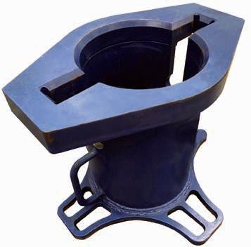
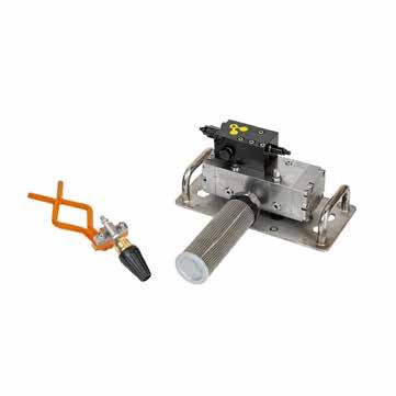
Zetechtics Subsea Torque Verification Class 1-4
Subsea class 1-4 torque tool calibration
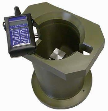
The Class 1-4 subsea torque tool verification system allows the ROV operators to prove the accuracy of a torque tool immediately before & after operating a client’s valve or subsea actuator. The system interfaces to API 17D Class 1-4 torque tool interfaces with three different stem sizes.
The system has an ‘inbuilt’ light sensor technology that enables the display only when illuminated by ROV lights., allowing the verification system (when deployed subsea) to remain dormant for months before operation.
Information can be recorded via ROV camera or captured into the Jupiter control system ‘data logging software’ (where applicable) or both.
Zetechtics Subsea Torque
Verification Class 1-4
Specifications
Interface Class 1-4 BS EN ISO 13628-8 2006
in air
in water 11.5kg
Maximum torque 2,711 Nm (2,000 lbf-ft) Weight
16.8kg Weight
Applications
Surface torque tool calibration
Features
ISO 13628-8 fig 18 (API 17D) class 1-4
Max torque 2711Nm / 2000ft lbs
Hand held digital read out
USB output to torque tool control system
Includes easily interchangeable shafts to suit full range
Configured for 17H and Petrobras
In the box
ISO 13628-8 Class 1-4 (API 17D)
Torque tool bucket inc sensor
Class 1 & 2 adaptor (11/16” Sq)
Class 3 adaptor (1-1/8” Sq)
Class 4 adaptor (1-1/2” Sq)
Handheld display
Transducer to display cable
Display to computer cable
Operations and maintenance manual
ISO 13628-8 Class 1-4 (API 17D)
Surface
Verification Unit
Surface class 1-4 torque tool calibration
This unit is used to give pre-dive surface confirmation of the torque tool calibration. It consists of a standard ISO class 1-4 torque reaction bucket with sturdy base and built in torque sensor. The unit comes complete with USB cable to connect to torque tool control system for auto calibration.
ISO 13628-8 Class 1-4 (API 17D)
Surface Verification Unit
Specifications
Torque interface ISO 13628-8 fig 18 class 1-4
Maximum torque 2711Nm / 2000ft lbs
Handheld unit Battery powered
Materials Steel shaft, aluminium housing
Applications
Subsea torque tool calibration
Features
ISO 13628-8 fig 18 (API 17D) class 1-4
Max torque 2711Nm / 2000ft lbs
4000m / 13,123ft rated
Interchangeable shafts
Self contained unit
Rechargeable battery or ROV power
In the box
ISO 13628-8 Class 1-4 (API 17D)
Dual Line USD
Battery pack
Subsea verification unit
Battery charger
Connection cables
PC calibration software
Class 1-2 shaft
Class 3 shaft
Class 4 shaft
Operations and maintenance manual
ISO 13628-8 Class 1-4 (API 17D)
Subsea Verification Unit
Subsea class 1-4 torque tool calibration
This unit has been developed to give subsea confirmation of torque tool calibration. It consists of a standard class 1-4 torque reaction bucket with a compact torque sensor. To change shafts only one bolt has to be undone.
Torque is displayed on separate universal subsea display unit. The display contains a power on indicator (green LED) and battery low indicator (red LED). The unit can operate continuously for 30 hours, but if no activity is detected after 10 minutes the unit will go into ‘sleep’ mode and the display will power down, sleep mode can be maintained for up to eight days. The display will ‘wake up’ as soon as there is a change in signal.
ISO 13628-8 Class 1-4 (API 17D)
Subsea Verification Unit
Specifications
Torque Interface ISO 13628-8 fig 18 class 1-4
Maximum torque 2711Nm / 2000ft lbs
Battery life 30 hours permanently on 200 hours in sleep mode (sleep mode auto on)
Materials Steel shaft, aluminium housing
Weight in air 22kg / 48.5lbs
Weigh in water 18kg / 39.6lbs
Applications
Surface torque tool calibration
Features
ISO 13628-8 fig 18 (API 17D) class
5 Max torque
6750Nm / 5000ft lbs
Hand held digital read out
Output to torque tool control system
In the box
ISO 13628-8 Class 5 (API 17D)
Torque tool bucket inc sensor
Handheld display
Transducer to display cable
Display to computer cable
Operations and maintenance manual
ISO 13628-8 Class 5 (API 17D)
Surface
Surface class 5 torque tool calibration
This unit is used to give pre-dive surface confirmation of the torque tool calibration.
It consists of a standard ISO class 5 torque reaction bucket with sturdy base and built in torque sensor. The unit comes complete with USB cable to connect to the torque tool control system for auto calibration.
ISO 13628-8 Class 5 (API 17D)
Surface Specifications
Torque interface
ISO 13628-8 fig 18 class 5
Maximum torque 6750Nm / 5000ft lbs
Handheld unit Battery powered
Materials Steel shaft, aluminium housing
Applications
Surface torque tool calibration
Features
ISO 13628-8 fig 18 (API 17D) class
7 Max torque
34,000Nm / 25,000ft lbs
Hand held digital read out
Output to torque tool control system
In the box
ISO 13628-8 Class 7 (API 17D)
Torque tool bucket inc sensor
Handheld display
Transducer to display cable
Display to computer cable
Operations and maintenance manual
ISO 13628-8 Class 7 (API 17D) Surface
Surface class 7 torque tool calibration
This unit is used to give pre-dive surface confirmation of the torque tool calibration. It consists of a standard ISO class 7 torque reaction bucket with sturdy base and built in torque sensor. The unit comes complete with cable to connect to the torque tool control system for auto calibration.
ISO 13628-8 Class 7 (API 17D)
Surface Specifications
Torque interface
ISO 13628-8 fig 18 class 7
Maximum torque 34,000Nm / 25,000ft lbs
Input square Class 7 (3.5” square)
Applications
17H valve operations
Features
ISO 13628-8 fig 14 high torque
Max torque 2000Nm / 1500ft lbs
Dual sensor electronic turns
counter
Internal strain gauge
In the box
Torque Tool
Fish tail handle
Bladder style compensator
All hoses supplied
Operations and maintenance
manual
High Torque Tool (API 17H) 100-2,000Nm 17H torque tool
This torque tool has been specifically developed to provide the highest level of performance. It has integral torque and turns count sensors. When matched with a PSSL supplied control manifold, it can provide precise feedback on torque response of any subsea operation.
The tool conforms to the ISO 13628-8 fig 14 high torque interface used extensively in the subsea industry for valve overrides operated by ROV.
The tool uses a high specification drive motor for consistent torque output characteristics under hydraulic pressure control.
High Torque Tool (API 17H)
Specifications
Torque interface
Torque range
Socket size
Motor size
Weight in air
Weight in water
Electrical connector
Recommended hydraulic fluids
CW
CCW
ISO 13628-8 fig 14
100-2000Nm / 73-1500ft lbs
35mm square
200cc
36kg / 79lbs
28kg / 62lbs
8 pin mini burton
Shell Tellus 22 or 32 Castro Hyspin AWS 22 or 32
4 JIC
4 JIC
Applications
Torque tool control operations
High-flow manifold control
FLOT operations
Features
4 off bi-directional solenoid valves (15lpm) adjustable pressure & flow on each valve
RS232 or RS485 options available
Surface software runs on PC or laptop
Compact & lightweight 4000m water depth rated
In the box
Jupiter 2 Torque Tool Control
System
Laptop
Operational hoses
Operations and maintenance manual
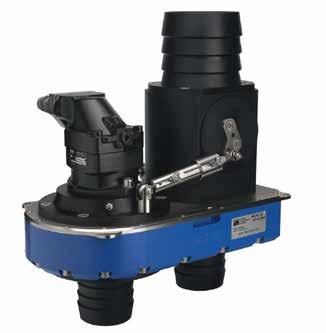
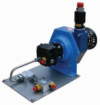
Zetechtics Jupiter 2 Torque Tool Control System
Jupiter 2 valve pack
The Jupiter 2 Torque Tool Control System offers an accurate & repeatable solution to client requirements for the control or torque tools in high integrity applications, the unit provides real time torque feedback and tool turns.
The system consists of a single valve pack with a fully integrated proportional control system. The unit is suitable for use with hydraulic torque tools operated from any Work Class ROV.
The system includes options for data-logger and features automatic calibration of the torque tools and sensors, users customisable set-up and comprehensive diagnostics.
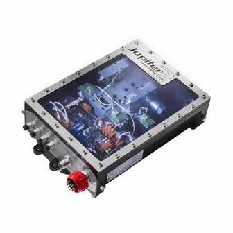
Zetechtics Jupiter 2 Torque Tool
Control System
Specifications
Outputs
Hydraulic input
Hydraulic output
Electrical supply
Weight in air
Weight in water
Depth rating
Hydraulic connections
1 off NG6 pressure & flow control
4 off NG3 bi-directional solenoid valves
40lpm (max) @ 250bar
15lpm @ 250bar
115v AC 50/60 Hz or 24v Raw DC
28kg
16.4kg
4000m
Pressure: 6 JIC
Return: 8 JIC
Comp: 4 JIC
Applications
Torque tool control operations
High-flow manifold control
FLOT operations
Features
1 off bi-directional pressure & flow control output
3 off bi-directional output
Strain gauge and turns count input
4000m / 13,123ft depth rated
RS232 or RS485 options available
External pressure sensor
In the box
TTCS Hydraulic Manifold
Panasonic Toughbook control PC
Interconnect cables
In-line filter
Operational hoses
Operations and maintenance manual
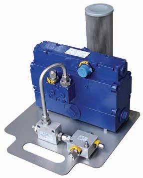
Torque Tool Control System
Multi-purpose
intelligent valve pack
The torque tool control system allows the user, from the surface, to adjust the torque and speed. This system is particularly suitable for deepwater operations where torque required for a particular operation may be uncertain, or has multiple values for different operations on the same dive. The actual torque and speed is user controlled and measured at all times and recorded as a signature of the subsea operation for future reference.
The controller can be used with any torque tool supplied by Ashtead Technology. The system can also be used as a pressure / flow controller for tools not equipped with feedback sensors.
Torque Tool Control System
Specifications
Outputs
Pressure sensor
Electrical inputs
Protection
Hydraulic input
Hydraulic output
Electrical supply
Connects with laptop controller
1 X 8 pin female feedback cable
1 X 8 pin mini burton female tail
3 off NG3 mini
1 off proportional pressure & flow
One on proportional pressure line
Strain gauge
Turns counter
Internal ground fault detection
External pressure relief valve
20lpm / 5.2gpm at 207bar / 3000psi
8lpm / 2.1gpm at 200bar / 2900psi (per station)
110VAC, 2A maximum
in air 18kg
Weight in water 14kg
6
Return Comp 6
6 JIC
Weight
/ 39.6lbs
/ 30.8lbs Pressure
JIC
JIC
Applications
Suction pile operations
High flow tooling operations
Features
NG6 bi-directional proportional pressure and flow valve
NG10 proportional pressure and flow valve
Differential pressure sensor
Flow meter input
In the box
High Flow Manifold
Connection cable to TTCS
Operational hoses
Operations and maintenance manual
High Flow Manifold High flow system for TTCS
The high flow manifold is an auxilary manifold that connects to the standard torque tool control system. The manifold contains an NG6 bi-directional proportional pressure and flow control and an NG10 proportional pressure and flow control valve. Also in the manifold is a differential pressure sensor used for suction pile operations. The manifold has an input for a optional flow meter. The standard torque tool control sytem software controls and displays readings from the manifold. Additionally input from an external gyro can be displayed on the software for suction pile operations.
High Flow Manifold Specifications
Working pressure
207bar / 3000psi
Maximum flow 80lpm / 21.1gpm
Weight in air 31kg / 68lbs
Dimensions 345 x 220 x 358mm / 13.5 x 8.6 x 14in
Applications
Class 1-4 valve operations
Paddle value operations
Features
Tool supplied with a calibrated torque wrench to allow accurate torque setting adjustment and predive verification
Lightweight construction
Smart socket
Fitted with torque resistant compliant mount
In the box
Fish tail handle
Calibrated torque wrench
Paddle valve interface
Operations and maintenance manual
Manipulator Held Clutch Tool
API 17D, ISO 13628-8 class 1-4
The Manipulator Held Clutch Tool is designed to allow the ROV manipulator operation of API 17D, ISO 13628-8 Class 1-4 rotary torque interfaces. The tool limits the torque that can be transmitted from the ROV manipulator to the valve stem during an ROV intervention operation, mitigating against the possibility of excessive torque being applied, ensuring damage to the valve does not occur. The tool is fitted with an integral, adjustable torque limiting clutch which can be pre-set for torque ranges of 20200 Nm. The front of the tool features a “smart” multi-socket interface which eliminates tool reconfiguration time on deck.
Manipulator Held Clutch Tool
Specifications
Depth rating Can be used at any water depth
Adjustable maximum torque settingFrom 20 to 200 Nm
Approx weight in air 14kg
Approx weight in water 12kg
Applications
Class 1-4 valve operations
Features
ISO 13628-8 fig 18 (API 17D) class 1-4
Max torque 2700Nm / 2000ft lbs
Manually operated torque tool built in 5:1 gearbox
Integrated carrying loop
Can be configured for 17H interface In the box
Class 1-4 Hand Operated Torque Tool
Gearbox assembly
Class 1-2, 3 and 4 sockets ¾” drive torque wrench
Operations and maintenance manual
Class 1-4 Hand Operated Torque Tool
Ideal for manual valve operations
The hand operated torque tool confirms to the ISO 13628-8 fig 18 interface requirements, it is supplied with a class 4 socket. Extra sockets can be supplied on request. The tool is intended for subsea operation to verify the interfaces on subsea equipment and to operate valves without the need for an ROV and a hydraulic supply.
The tool has a built in 5:1 gearbox to supply torques up to 2700Nm by hand. The tool is supplied with a torque wrench so torques can be accurately applied.
Class 1-4 Hand Operated Torque Tool
Specifications
Torque interface
Torque range
Socket size
Gearbox ratio
Materials
ISO 13628-8 fig 18 class 1-4
30-2700Nm / 22-2000ft lbs
Class 1-2, 3 and 4
5:1
Steel motor and gearbox, duplex socket, aluminium housing and acetal hose
Applications
17H valve operations
Features
ISO 13628-8 class 4 female bucket
API 17H male interface 35mm AF square Max torque 2700Nm / 2000ft lbs
In the box
17D-17H Adapter 900Nm / 663ft lbs sheer pin 2700Nm / 2000ft lbs shear pin
Operations and maintenance manual
Ashtead Technology
17D to 17H Adapter
Convert class 1-4 to 17H high torque interface
The adaptor is used to convert from ISO 13628-8 class 4 (API 17D) to API 17H high torque interface. Shear pins are supplied with the tool to protect the high torque interface from over torque.
Ashtead Technology 17D to 17H Adapter
Specifications
Female interface ISO 13628-8 fig 18 class 4
Male interface ISO 13628-8 fig 14 high torque
Maximum torque 2700Nm / 2000ft lbs
Weight in air 14kg / 30.8lbs
Weight in water 10kg / 22lbs
Applications
Manual valve operations
Features
ISO 13628-8 fig 18 (API 17D) class 1-2
Direct manipulator operation
Stainless steel construction
Class 1-2, Class 3, Class 4 High torque
In the box
Manipulator Operated Torque Tool
Operations and maintenance manual
Manipulator Operated Torque Tool Ideal for manual valve operations
The tool is used to operate ISO Class 1-2, 3 or 4 interfaces without the use of a torque tool. The tool utilises the rotate function on the manipulator to generate the required torque.
Manipulator Operated Torque Tool
Specifications
Interface ISO 13628-8 fig 18 class 1-2, 3 or 4 socket
Maximum torque Dependant on manipulator
Materials Stainless steel
Weight in air 3kg / 6.6lbs
Weight in water 2kg / 4.4lbs
Applications
Linear valve operations
Features
Range of interfaces
Up to 100t force
Range of strokes up to 10.75"
Hydraulic set, mechanical locked Manipulator or diver deployed
Can be configured for different stroke sizes
Actuator operated with either hand pump or 10K panel
In the box
LAOT actuator
LAOT locking head
ROV handle
Operational hoses
Operations and maintenance manual
Linear Actuator Override Tool (LAOT)
5.8" strokes and 10.75" strokes
Linear actuator override tools are available in a range of loads up to 100 tonnes. The tool supplied usually comprises two parts, the locking head, and the actuator. The actuator contains a hydraulically operated piston powered by an intensifier. Actuators can be supplied with hot stabs and check valves. The locking head is a purely mechanical device and is left behind on a subsea interface when the valve is required to be let over-ridden.
Interfaces available are ISO 13628-8 Type A, ISO 13628-8 Type B and customer specific two lug interface. A range of strokes are available to suit specific applications.
Linear Actuator Override Tool (LAOT) Specifications
Interface
Maximum load
Maximum pressure
Operating flow range
ISO 13628 Type A,B
Up to 100t
690bar / 10,000psi
2-14lpm / 0.5-3.7gpm
ISO 13628 Type A,B
Up to 100t
690bar / 10,000psi
2-14lpm / 0.5-3.7gpm
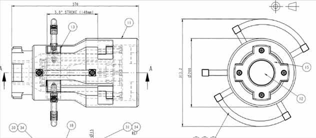
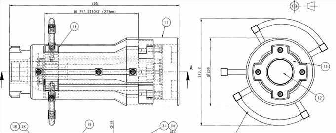 5.8" Strokes
10.75" Strokes
5.8" Strokes
10.75" Strokes
5.8" Strokes
10.75" Strokes
5.8" Strokes
10.75" Strokes
Applications
Flying lead operations
Class 1-4 torque tool operations
Features
+/- 15 deg roll angle
+60, - 90 degrees pitch
Counter-balance valve on both
actuators
250kg / 551.1lbs payload
In the box
Flying lead orientation tool
Adaptor to fit torque tool
Operational hoses
Operations and maintenance
manual
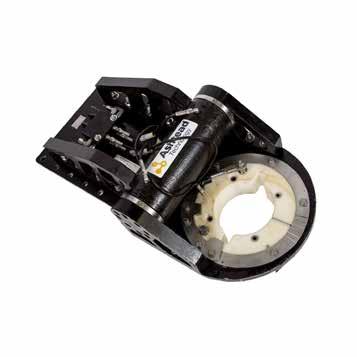
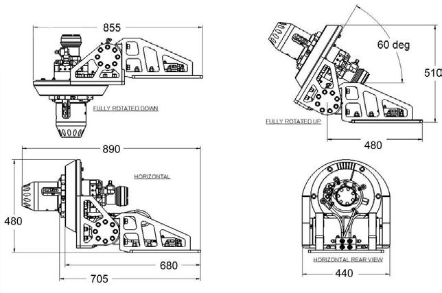
Upright FLOT Flying lead installation and removal
The FLOT tool is designed to operate in conjunction with a torque tool and is used to orientate and guide flying leads into the stab plate connections. The FLOT tool is designed to take the PSS class 1-4 torque tool, but can easily accommodate similar tools from other manufacturers. A rotary actuator allows a pitch alignment of plus 60 or minus 90 degrees with a load of up to 250kg attached. The tool is also equipped with a roll alignment function giving a rotation of plus or minus 15 degrees.
The FLOT tool is compact and the tool mounting base is supplied with a selection of mounting holes for mounting within the forward structure of the ROV. The pitch and roll actuators can be controlled from the TTCS or ROV’s spare directional control valves.
Upright FLOT Specifications
Pitch Rotation
Payload capacity
Hydraulic control from ROV
Operating fluid
Operating pressure
Hydraulic fittings
Weight in air
Weight in water
CCW
CW
Up
Down
+60, - 90 degrees
+/- 15 degrees
250kg / 551lbs mounted on torque tool, through full range of travel Two off bi-directional solenoid control valves plus drain
Hydraulic oil
207bar / 3000psi
JIC or swagelok
77kg / 169lbs
57kg / 125lbs
4 JIC
4 JIC
4 JIC
4 JIC
Applications
Torque tool feedback Pressure transducer feedback Flow counter
Features
Power input range 3.5v-35v
User-friendly configuration
software
Rugged construction
3000m / 9842ft depth rated
External battery
Multiple functions
Up to 240hrs standby
Up to 48hrs of continious
operations
In the box
Universal Subsea Display (USD)
Battery pack
Battery charger
Programming cable
Programming software
Battery pack to USB cable USD to torque tool cable
USD to ROV flying lead (power)
Function labels
Operations and maintenance manual
Universal Subsea Display (USD) Display electrical signals subsea
The Universal Subsea Display (USD), displays information from a wide range of sensor types. It is viewed using ROV cameras or directly by divers. The USD is housed in a robust anodised aluminium alloy housing with an integrated compensator. The unit is available with a two line display (6 digits per row) or a single line (4 digits and a minus sign). The two line display can display information from two separate inputs.
The USD readily interfaces to equipment through two subsea connectors. The first connects to a battery pack or a vehicle / tooling package with both power and communication. The second connects to the equipment to be monitored providing the interfaces for sensing and the supplies for powering the equipment sensors.
The USD uses ultra-efficient LED types, a very low power processor and sophisticated power switching regulators which, together, mean it can operate from a wide DC voltage input range, requiring very low current and equally able to operate from ROV supply or from battery. In addition, it has a software configurable sleep mode with option to wake up on sensor activity or from the light sensor on the front face. The unit can be configured for a multitude of applications.
Universal Subsea Display (USD)
Specifications
Depth rating
Available sensor inputs
Sensor supplies
Sensor supply protection
Serial out
Input voltage
3000m / 9842ft
Strain gauge bridge (full Wheatstone)
0-5V & 0-10V analogue voltage
4-20mA analogue current
PNP or NPN type contact / proximity
Contact closure - reed switch / digital
1 off 5V to 250mA
1 off 12V to 500mA
Current limited & short circuit protected
RS232 or RS485 (software selectable)
3.5 - 35V DC (reverse polarity protected)
Applications
Rotary valve operations
Stab plate operations
Features
ISO standard interface
Full suite of supporting tools
Twin point docking
Buoyancy block
In the box
Tool Deploment Unit (TDU)
High torque tool
Class 1-2 torque tool
Operations and maintenance manual
10 x 8 cabin
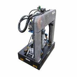
Tool Deployment Unit (TDU) ROV workskid and tool deployment unit
The Tool Deployment Unit (TDU) is used where subsea equipment has been designed around this ISO interface. It has the advantage of giving a high degree of precision when deploying tools.
The unit conforms to the ISO interface requirements with the full range of supporting tools: including torque tool, gripper, stab plate and linear override tools.
The system is fitted to a host ROV, usually at rear, and is controlled over its own data link from a laptop computer. The operating software includes the Forum torque tool control suite with full turns and torque feedback as standard.
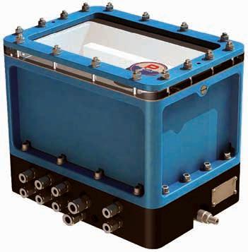
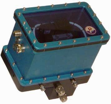
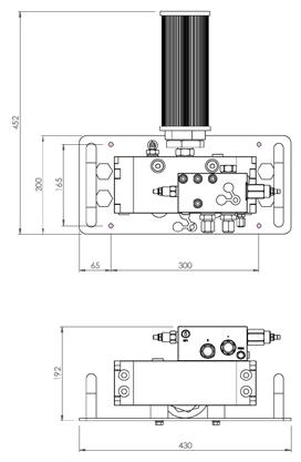
Tool Deployment Unit (TDU)
Specifications
Host ROV requirements
RS485 / RS232 data link
Hydraulic Supply 20lpm / 200bar
Standard working pressure 207bar / 3000psi
Depth rating Buoyancy block to client requirement, max 4000m
Weight in air/water 562kg / 0kg (with 1500m buoyancy rating)
Cameras
Lights
Hydraulic functions
4 off with zoom and focus control
2 off with dimmer control
8 off NG3 switching DCV
1 off NG6 proportional DCV
Applications
Site Integration Testing (SIT)
Valve access simulation
Operational access simulation
Features
7 function manipulator
5 function manipulator
Smart valve packs
In the box
Mock-up ROV Control van
Workshop
Mock-up ROV (MROV)
Site integration testing
The mock-up ROV system is used to carry out onshore site integration testing (SIT) to ensure that ROV-operable functions can be tested for accessibility and functionality prior to subsea deployment.
Our unit is based on a standard ROV frame format including imitated buoyancy, a 5 function manipulator and intelligent valve pack. Optional configurations include a 7 function manipulator and other tooling requirements such as a FLOT tool or multipurpose skid.
Operations are managed from the control van, with operational points for controlling ROV tooling and manipulators. An IP camera system allows for remote access, negating the need to be physically present on-site for the duration of testing.
Mock-up ROV (MROV) Specifications
Hydraulic system
Control system
Supply requirements
Mock-up ROV weight
Control van weight
Mock-up ROV dimensions
Aircooled built-in HPU
210bar / 3000psi
20-55lpm / 4.5-14.5gpm
Forum SVP with proportional control
1 master IP camera
2 slave IP cameras
1 roving IP camera
Remote access for camera system via web browser
440v 63 Amps three phases
1,160kg / 2557lbs (including 7 & 5 Function manipulator)
6,000kg / 13,228lbs
Length: 2,540mm / 8ft 4in
Width: 1,420mm / 4ft 8in
Height: 1,850mm / 6ft 1in
Length: 6,058mm / 20ft
Width: 2,438mm / 8ft
Height: 2,896mm / 9ft 6in
2
01 Valve manipulation tools & accessories 02 Dredging & jetting 03 Cutters & grinders 04 Subsea pumping & injection 05 Topside pumps 02
& jetting
Section
Dredging
Applications
ROV dredging work
Excavation
Removal of gravel, rocks & sediment
Features
Compact dredge designed for easy mobilisation
Lightweight with low power requirements
Compensated, no depth limitations or risk of water ingress
In the box
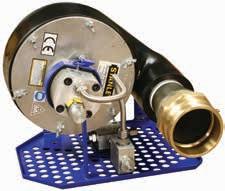
WeSubsea Hydraulic ROV Dredge
3 x certified hydraulic hose
@3m long with 08 JIC female swivel
4m suction hose with camlock for mounting on dredge Suction head with fishtail 0.5m long, 45 degrees
Suction head 0.7m long, 45 degrees
Discharge extension hose 0.9m
2 x hose lock clamps
2 x gaskets
Optional hot stab
Additional spare parts and custom parts on request
WeSubsea Hydraulic ROV Dredge
Lightweight
titanium high-performance dredge
Ashtead Technology’s WeSubsea Hydraulic ROV Dredge’s are designed with a focus on performance. The dredge’s are supplied as a complete out of the box dredging package with no external pump units or further hardware to assemble. These highly efficient dredge’s are supplied ready to be mounted on to the ROV for quick and easy operation.
6 JIC female
6 JIC female
6 JIC female
8 JIC female
8 JIC female
8 JIC female
8 JIC female
8 JIC female
8 JIC female
8 JIC female
8 JIC female
8 JIC female
8 JIC female
8 JIC female
8 JIC female
8 JIC female
8 JIC female
8 JIC female
8 JIC female
8 JIC female
8 JIC female
8 JIC female
8 JIC female
8 JIC female
Removal
8 JIC female
8 JIC female
8 JIC female
54kg
120kg
24kg 18kg 952 x 639 x 365mm
38kg 30kg 1200 x 800 x 800mm
120kg
41kg 32kg 1296 x 699 x 579mm
200kg
75kg 63kg 1200 x 800 x 800mm
300kg
95kg 75kg 2400 x 800 x 800mm
300kg
95kg 75kg 2400 x 800 x 800mm
300kg
Specifications:
(2300lpm) 65mm 18 (28t/hr) 15-22lpm @140-200 bar
26 (41t/hr) 18-23lpm @ 140-200 bar
38 (61t/hr) 30-50lpm @170-200 bar
205 (3,400lpm) 90mm
118 (1970lpm) to 140
162 (2,700lpm) to
292 (4867lpm) 90mm
498 (8300lpm) 140mm 45 (70t/hr) 50-60lpm @ 200 bar
70 (110t/hr) 70lpm @ 200 bar
84 (130t/hr) 150lpm @ 200 bar
95kg 75kg 2400 x 800 x 800mm
300kg
3"
4"
4 High capacity" 6"
185mm
708 (11800lpm)
1002 (16700lpm) 185mm
90 (140t/hr) 70lpm @ 200 bar
230mm
8"
8" High capacity
785 (13500lpm)
300kg
2400 x 800 x 800mm2400 x 800 x
800mm
75kg 95kg
108 (168t/hr) 150lpm @ 200 bar
1223 (20383lpm) 230mm
82kg 103kg
108 (168t/hr) 150lpm @200 bar
1482 (24700lpm) 270mm
10" 12"
10" High capacity"
WeSubsea Hydraulic ROV
Specifi cations
Dredge
flow rate (m³/h) Max rock size (theoretical) Hydraulic requirement Weight in air Weight in water Dimensions (LxWxH) Weight Pressure Return Case drain Shipping: Hydraulic
Max
connections:
capacity (m³/h (t/hr))
Applications
Excavation
Removal of gravel, rocks and sediment
Features
Designed to move different types of sediment on the seabed
Powered by Top Side HPU for water depth to 300m
Powered by ROV hydraulics through HotStab for deeper water depths
Lightweight and compact design
Suction hose 20m +, soil dependent
Operated by diver or ROV
Can be fitted with flexible discharge hose
Suction hose and discharge hose can be mounted subsea using a slip over flange
In the box
WeSubsea Diver Dredge Certified hydraulic hoses with Aero-Quip couplings
Suction hose with slip-on flange
Back flush
Suction head with D-handle Hose lock clamps
Optional hot stab
Optional discharge hose
Additional spare parts and custom parts on request
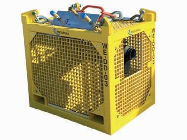
WeSubsea Hydraulic Diver Dredge
Stand-alone titanium diver dredge system
Ashtead Technology’s WeSubsea Hydraulic Diver Dredge's are stand-alone system designed for excavation and removal of gravel and sediment. Built with safe operations as a priority, the system comes with hydraulic back flush and can be operated with diver or ROV.
The WeSubsea Hydraulic Diver Dredge suits a range of subsea applications including deep-water dredging, debris removal, rock dump and drill cut removal, pipeline deburial, excavation and environmental work. Ashtead Technology’s WeSubsea range includes the lightest and most efficient dredges on the market today.
460kg
Hydraulic
Max rock size (theoretical)
2000x800x1500mm
460kg
460kg
2000x800x1500mm
2000x800x1500mm
500kg
1200x800x800mm
2000x800x1500mm 500kg
500kg
500kg
2500x800x1500mm
2500x800x1500mm
500kg
Max flow rate (m³/h)
205 (3400Lpm) 90mm 26 (41t/hr) 23Lpm @ 200 bar
292 (4867Lpm) 90mm 38 (61t/hr) 150Lpm @ 200 bar
292 (4867Lpm) 90mm 38 (61t/hr) 50-60Lpm @ 200 bar
708 (11800Lpm) 185mm 70 (110t/hr) 70Lpm @ 200 bar
1002 (16,700Lpm) 185mm 84 (130t/hr) 150Lpm @ 200 bar
785 (13,500Lpm) 230mm 90 (140t/hr) 70Lpm @ 200 bar
1223 (13,500Lpm) 230mm 108 (168t/hr) 150Lpm @ 200 bar
2500x800x1500mm
1686 (28,100Lpm) 270mm 108 (168t/hr) 150Lpm @ 200 bar
4"
4" High capacity 6" 8"
8" High capacity
10" 12"
10" High capacity"
Specifications
WeSubsea Hydraulic Diver Dredge
requirement Removal capacity Dimensions Weight
Applications
Work-class ROV construction
Work-class ROV drill support
Relocation of mud, silt and rocks
Relocation of drill cutting
Marine archaeology
Salvage operations
Features
Excavates seabed sand, gravel, clay and rocks
Power efficient electric motor
No hydraulics required
Small deck area required
ROV friendly hose connection
Proven reliability
Compact design
Superior performance
Compliant to IEE wiring regulation (BS7671)
Compliant to IMCA DO45 (safe use of electricity underwater)
Bespoke options
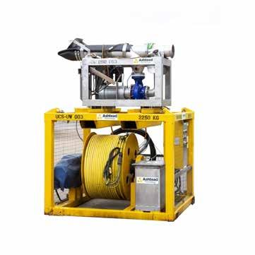
UCS have specialist in-house design and fabrication capabilities and are able to modify any tool to suit client / project requirements.
UCS Dredge System (12', 8'' and 6') Electrical dredge system
This electrically-driven 12” dredge system allows the excavation of seabed sand, gravel, clay and rocks up to 254mm (10”) in diameter.
Regardless of the dredge size chosen, the UCS electrical dredge system utilises a reduced deck footprint by removing the need for large hydraulic umbilical reels and power units as required by hydraulic dredging systems. Replacing hydraulic hoses with an electrical umbilical eliminates the considerable power losses associated with transferring hydraulic oil through long hose lengths. The use of electric power also negates the risk of environmental damage due to oil leakage or loss. As a result, UCS systems offer superior suction and efficiency compared to hydraulic dredges.
Our standard offering comprises of an umbilical winch, skid unit, 10m suction hoses and spares package, with bespoke revisions also available.
Umbilical winch dimensions
1685mm / 66.4in
1964mm / 77.3in x 2067mm / 81.4in x
Dredge skid dimensions
Dredge umbilical winch
Dredge skid mass in air
Standard exhaust hose length
Standard suction hose length
1898mm / 74.7in
4000kg / 8818lbs 2576mm / 101.4in x 1990mm / 78.4in x
na 2450kg / 5401lbs
Max rock size
Suction rate
Electrical requirements
Dredging capacity
ID 305mm / 12in @ 10m/5m/4m
254mm / 10in
10400lpm / 2746gpm @ 60Hz
3 phase 440v, 50-60Hz, 125amp
waste content
640 cubes p/h (100% water) rate varies with
59in
2000mm / 78.8in x 1700mm / 67in x 1500mm /
47.3in
680kg / 1499lbs 2250kg / 4960lbs 1690mm / 66.5in x 800mm / 31.5in x 1201mm /
ID 250mm / 9.8in @ 1m
ID 200mm / 8in @ 10m / 32.9ft
140mm / 5.5in
5300lpm / 10630gpm @ 60Hz
3 phase 440v, 63amp
waste content
320 cubes p/h (100% water) rate varies with
Specifications
1500mm / 51.2in
1800mm / 70.9in x 1700mm / 59in x
1033mm /40.7in
470kg / 1035lbs 1500kg / 3307lbs 1608mm / 63.3in x 700mm / 27.6in x
ID 200mm / 8in @ 1m
ID 150mm / 6in @ 10m / 32.9ft
102mm / 4in
2600lpm / 687gpm @ 60Hz
3 phase 440v, 32amp
waste content
180 cubes p/h (100% water) rate varies with
UCS 12' ' Dredge System
UCS 8 '' Dredge System
UCS Dredge System (12'', 8'' and 6'')
UCS 6 '' Dredge System
Applications
ROV dredging work
Excavation
Removal of gravel, rocks & sediment
Features
Quick and easy to mobilise
No depth limitations
Designed for rapid deployment
In the box
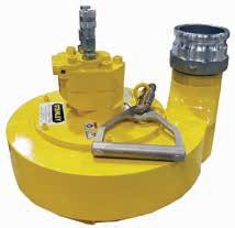
Vortex Dredge
Operations and maintenance manual
Operational hoses
Vortex Dredge
The most powerful 4in, 6in & 8in dredge on the market
The Vortex Dredge's are designed for subsea excavation and disposal of seabed materials. The Vortex Dredge's can be mounted onto any work class ROV without requiring deck space or sea fastening. With no moving parts, this powerful dredge is quick and straightforward to mobilise.
Vortex Dredge
Specifications
Debris removal rates (ton / hr)
Venturi inner diameter
Rated maximum stone size
Suction hose diameter
Exhaust hose diameter
Inlet suction hose length
Exhaust throw length
Hydraulic flow required
60t per hour, 27m³/hr, 15% solids by volume
100mm / 4in
100mm / 4in
100mm / 4in
100mm / 4in
Up to 40m
Up to 4m
78lpm
Hydraulic pressure required 165bar
Optimum pressure
206bar / 3000psi
Available suction at inlet 100kpa
Optional Jetter nozzle water pressure60psi
Up to 80t per hour, 30m³/hr, 10% solids by volume
150mm / 6in
149mm / 6in
149mm / 6in 149mm / 6in
Up to 40m
Up to 4m
78lpm
206bar
206bar / 3000psi
Up to 128t per hour, 5860m³/hr, 10% solids by volume
200mm / 8in
198mm / 8in
202mm / 8in
202mm / 8in
Up to 40m
Up to 4m 52kpa 60psi
206bar
206bar / 3000psi
Hydraulic hose requirements:
return
in
50kg
in water 39kg Operation in air No 4" 6" 8"
Weight
air
Weight
99kg 76kg No
60psi 111kg 89kg No
32kpa
85lpm
2 x 12 JIC 1 x 6 JIC 2 x 4 JIC 2 x 8 JIC 1 x 6 JIC 2 x 4 JIC 2 x 8 JIC 1 x 6 JIC 2 x 4 JIC
Pressure &
Case drain Reversal valve
Applications
Relocation of mud, sand, gravel, clay and rocks up to 205mm (8in in diameter)
Features
ROV-friendly cradle
Proven reliability
Compact design
Superior performance
Manufactured from carbon steel with neoprene gaskets
Easy assembly and operation
Bespoke options
UCS have specialist in-house design and fabrication capabilities and are able to modify any tool to suit client / project requirements.
UCS 10in Air Lift Dredge
For excavation of seabed sand, gravel, clay and rocks
This Air Lift Dredge system is designed for effective excavation of seabed sand, gravel, clay and rocks up to 205mm in diameter, in water up to 50 MSW.
The system has no exposed pipe work, delivering the water and air requirements internally which limits any snagging and hose damage. High flow water is supplied to the suction head to lower the density of the material to be dredged. Adjustable jetting nozzles can be moved to deliver horizontal, vertical or 45-degree jetting depending on the project requirements. High volume compressed air is forced in to the 10in pipe work creating a high rate suction force caused by the pressure differential ensuring loosened debris is ejected safely through the exhaust.
The 10in airlift dredge is to be used with a high volume water pump, lift pump, umbilical
UCS 10in Air Lift Dredge
Specifications
System flow rate
Suction pipe ID
Suction pipe length
Exhaust pipe ID
Exhaust pipe length
Max rock size
Air requirement
Water pump requirement
Mass in air
Dimensions (L x W x H)

>15,000lpm / >3963gpm
260.3mm / 10in
23m / 75ft
260.3mm / 10in
Horizontal displacement
205mm / 8in
28.3cubic metre/minute @ 14bar / 1000cfm @ 203psi
1,000m³/hr @ 14 bar / 35314ft³/hr @ 203psi
4800kg / 10582lbs
23.7m / 78ft x 900mm / 53.4in x 900mm / 53.4in
Applications
Work-class ROV construction
Work-class ROV drill support
Pile & hollow structure dredging
Relocation of mud, silt and rocks
Marine archaeology
Features
Power efficient electric motor
No hydraulics required
Depth monitoring
Water jetting attachment
Compliant to Lifting Operations and Lifting Equipment Regulations
SI 1998 No 2307
Compliant to IEE wiring regulation (BS7671)
Compliant to IMCA DO45 (safe use of electricity underwater)
Bespoke options
UCS have specialist in-house design and fabrication capabilities and are able to modify any tool to suit client / project requirements.
UCS Pile Cleaning System
Electrical dredge system
The UCS pile cleaning system is ideal for cleaning sand, debris and clay from piles. The suction hose is supported off the vessels crane and the solid pipe for the suction end can be installed with a high pressure jet, if required for clay conditions.
The suction hose set up can be adapted to suit specific project requirements.
UCS Pile Cleaning System
Specifications
Dredging capacity (as standard) 320 cubes p/h (100% water) rate varies with waste content
Electrical requirements 3 phase 440v, 63amp
Suction rate 5300lpm / 10630gpm @ 60hz
Max rock size 140mm / 5.5in
Standard suction hose ID 200mm / 8in @ 20m / 65.8ft
Standard exhaust hose ID 250mm / 9.8in @ custom
Dredge skid mass in air 680kg / 1499lbs
Dredge chute mass in air (with hose)132kg / 291lbs
Dredge umbilical winch
Dredge skid dimensions
Umbilical winch dimensions
2250kg / 4960lbs
1740mm / 68.5in x 800mm / 31.5in x 1191mm / 46.7in
2000mm / 78.8in x 1700mm / 67in x 1500mm / 59in
Applications
Break up and excavation of sea bed
Removal of drill cuttings
Clearing of seabed manifolds
Removal of soft marine growth
Marine archaeology
Treasure hunting and salvage
Features
Robust and compact design
Will not block or jam
Easy in-field maintenance
ROV mounting system
Modular pump core
Mulitple mounting configurations
In the box
Tritech Super ZipJet
Jetting nozzle
Dredging nozzle
Operational hoses
Operations and maintenance manual
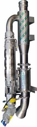
Tritech Super ZipJet
Lightweight ROV dredge pump
The Tritech Super ZipJet ROV dredge pump replaces the successful Tritech ZipJet Ultra range of suction & jetting systems.
The Super ZipJet pump incorporates many technical advances over the previous generation of ROV suction and jetting systems. These advances are a direct result of customer feedback.
Considerable emphasis has been placed on increasing the pump’s efficiency in both the suction and jetting modes. The Super ZipJet pump incorporates several design features which improve its reliability and substantially reduce its maintenance costs.
The Super ZipJet pump will not block or jam because there are no moving parts on the dredging side of the system. Power is derived from a stream of high velocity fluid creating a low-pressure region behind the suction nozzle. The pump may be rapidly switched from suction to jetting mode.
Tritech Super ZipJet
Specifications
Hydraulic motor pressure
Hydraulic motor flow
Actuator minimum pressure
Actuator maximum pressure
Jetting performance
Suction flow
Solids removal rate
Jetting
Discharge
Suction
Clean water inlet
Weight in air
Weight in water
Materials
Pressure & return
Case drain
Acuators
150-220bar / 2175-3190psi
40-60lpm / 10.5-15.8gpm
110bar / 1595psi
240bar / 3480psi
1000lpm/264gpm @ 2bar / 29psi
500-1000lpm / 132-264gpm
5-10t per hour
25mm ID / 1in
100mm ID / 4in
75mm ID / 3in
100mm ID / 4in
25kg / 55lb
11kg / 24lb
Nylacast, UHMWPE
12 JIC
6 JIC
4 x 4 JIC hoses
• 1 x 1" Medusa 5m length
• 1 x 3" Medusa 5m length
• 2 x 4" Medusa 5m length
Applications
Break up and excavation of sea bed
Removal of drill cuttings
Clearing of seabed manifolds
Removal of soft marine growth
Marine archaeology
Treasure hunting and salvage
Features
Robust proven design
Small and light
Rapid switch from suction to jetting
Modular pump core
Reverse flush for suction nozzle
Double shaft seal
Option of close fitting inlet strainer
Fitted to most work class ROVs
In the box
Merlin ROV Pump
25mm/1in jetting nozzle
100nn/4in eductor nozzle
Clean water inlet filter
High-flow pilot operated valve
Operational hoses
Operations & maintenance manual
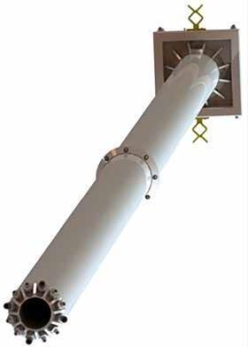
Tritech Merlin Pump
Robust excavation pump that will not block or jam
The Tritech Merlin is a smaller, lighter and more robust pump with greater performance in both excavation and jetting functions. It features the same double seal arrangement as the Super ZipJet dredge pump and its modular design provides great ease of maintenance.
These are significant efficiency increases in both the impeller and eductor making this the tool that no work-class ROV should be without. As with all Tritech pumps, the merlin will not block or jam because there are no moving parts in the suction flow path.
The flow reversal valve can be operated to back flush the suction nozzle should there be an construction. Power is derived from a stream of high velocity fluid creating a low pressure region behind the suction nozzle.
The pump may be rapidly switched from suction to jetting, or be configured to an intermediate position allowing jetting and excavation to be carried out simultaneously.
Tritech Merlin Pump
Specifications
Hydraulic motor pressure
Hydraulic motor flow
Actuator minimum pressure
Actuator maximum pressure
Jetting performance
Suction flow
Solids removal rate
Jetting hose
Jetting nozzle diameter
Discharge hose diameter
Suction hose diameter
Weight in air
Weight in water
Materials
Pressure & return
Case drain
Actuators
170-250bar / 2465-3625psi
65-110lpm / 17 to 29gpm
120bar / 1740psi
240bar / 3480psi
Up to 600lpm / 158 5gpm @ 8bar / 116psi
2000-4000lpm / 528 - 1056gpm
10-40t per hour
25mm / 1in BSP hose barb
20mm / 0.8in
150mm / 6in
100mm ID / 4in
40kg / 90lb
17kg / 38lb
Stainless steel, Nylacast UHMWPE
12 JIC hose
6 JIC hose
4 x 4 JIC hoses
• 1 x 1" Medusa 5m length
• 1 x 3" Medusa 5m length
• 2 x 4" Medusa 5m length
Applications
ROV dredging operations
Removal of drill cuttings
Clearing of subsea manifolds
Removal of soft marine growth
Marine archaeology
Treasure hunting and salvage
Features
TP03:
Submersible and self-priming
Dredge solids up to 75mm (3in) in size
Easy bowl inspection and clean out Build in reverse flow check
Can run dry without damange CE certified
TP08:
Submersible and self priming
Dredges solids up to 100mm (4in) in size
Easy volute inspection and clean out
Can run dry without damage
In the box
TP03 or TP08 Trash Pump
ROV dredging nozzle
Operational hoses
Operations and maintenance manual
Stanley TP03 & TP08 Trash Pump
Ideal for dredging and cleaning tasks
The Stanley TP03 submersible trash pump boasts 450gpm of output flow, this is an efficient way to move large volumes of liquid with concentrations of solids up to 25% by volume. The TP03 handles solids up to 3 inches in size and is used for dredging and light cleaning tasks.
The Stanley TP08 heavy duty trash pump is used for dewatering, dredging, cleaning and as a effective bilge pump. The gear motor is direct drive to the cast iron impeller with easy access for clean out of fabricated steel volute. The TP08 uses only 9gpm/34lpm of hydraulic flow, the unit will pump over 800gpm (3,028lpm) and a 10ft (2.54m) head. The free-flow Impeller and 4in (100mm) inlet and outlet combine to make to TP08 ne of the most efficient pumps in the business.
 Stanley TP03
Stanley TP08
Stanley TP03
Stanley TP08
Stanley TP03 & TP08 Trash Pump
Specifications
Capacity
Pressure
Flow range
Porting
Connect size & type
Discharge diameter
Inlet diameter
Weight
Height (over handle)
Length
Width
TP03
1688lpm
105-140 bar (1500-2000psi)
26-34lpm (7-9 gpm)
1/2in NPTF
1/2in male pipe
75mm (3in camlock)
75mm (3in)
14kg
420mm (16.5in)
355mm (14in)
410mm (16in)
TP08
3028lpm / 800gpm
140bar / 2000psi
26-38lpm / 7-10gpm
#10 SAE (pressure) #12 SAE (return)
1/2in male pipe
100mm / 4in camlock
100mm / 4in
26.7kg
420mm / 16.5in
483mm / 16.5in
381mm (15in)
Applications
Light subsea cleaning operations
Pumping & injection operations
Features
Numerous nozzles available
Mounted on ROV friendly plate
PO check valve
Flow control valve
Integral relief valve (0.5-520bar)
In the box
0-520bar Jetting System
T bar nozzle handle
Turbo nozzle
Suction filter
Basic spares kit
Operational hoses
Operations and maintenance manual
1 x spare filter
Ashtead Technology 0-520 Bar Jetting System
High pressure water jetting system
The 0-520bar jetting system is widely recognised and used throughout world due to its reliability and impressive pumping capabilities; no other system offers the same power and reliability. The Integral relief valve is adjustable to provide any pressure range desired from 0.5-520bar.
The pump is suitable for connection to any subsea reservoir via the ¾ suction port. The system is designed to be capable of pumping water, sea water, hydraulic oil or glycol. This highly versatile system can be used as either an IHPU or Jetting system making it an invaluable and effective tool for any ROV system.
Ashtead Technology 0-520 Bar
Jetting System
Specifications
Hydraulic input pressure
Hydraulic input flow
Hydraulic output pressure
Hydraulic output flow
Maximum jetting
Dimensions
Weight in air
Fluids
180-210bar / 2610-3045psi
30-60lpm / 8-16gpm
0.5-520bar / 7.25-7500psi
15-30lpm / 4-8gpm
400bar / 5801psi (Standard nozzle)
431mm x 345mm x 233mm / 17 x 13.5 x
9.1in 27kg / 59.5lbs
Water, sea water, hydraulic oil and glycol
Pressure & return 2 x 8 JIC female swivel hose, 4m
Output 1 x AJIC swivel hose, 1m
Pilot 1 x AJIC female swivel hose, 1m
Applications
Water jetting operations
Suction pump operations
Features
435lpm / 115gpm output
Simple and reliable jetting solution
Range of jetting nozzles available
Can be controlled to suction upon request
In the box
Low Pressure Jetting System
ROV jetting handle
Operational hoses
Operations and maintenance
manual
Low Pressure Jetting Unit
Low pressure, high flow water jetting system
Designed for use when our high pressure jetting system offers too much power for the application, the low pressure system is as reliable, durable and simple to use providing a constant water jet stream at a maximum of 435lpm.
Mounted on an ROV friendly stainless steel plate this unit is shipped ready for immediate integration and operation.
Low Pressure Jetting Unit
Specifications
Hydraulic input pressure 150bar / 2175psi
Hydraulic input flow 27lpm / 7.1gpm
Maximum output pressure 6.4bar / 92.8psi
Maximum output flow 435lpm / 115gpm
Pressure & return
Pilot
Output
2 x 6 JIC female swivel hoses, 4m
1 x 4 JIC female swivel hoses, 4m
1 x 12 JIC female hoses, 4m
Applications
High-flow cleaning
Pumping & injection operations
Features
150lpm jetting capabilities
Cavitation nozzle cleans without causing damage
Numerous nozzle designs
In the box
150lpm Cavitation Jetting System
Jetting nozzle
ROV handle
Dual, tripple and quad nozzle
C-spanner
Operational hoses
Operations and maintenance manual
150Lpm Cavitation Jetting System
High-flow cavitation water jetting system
The 150lpm jetting system is widely recognised and used throughout world due to its reliability and impressive pumping capabilities; no other system offers the same cleaning power and reliability.
Utilising a specially designed nozzle to induce cavitation this unit has been proved to be a highly effective cleaning tool which does not cause damage to delicate surfaces.
The pump is suitable for connection to any subsea reservoir via the ¾ suction port and is capable of pumping water, sea water, hydraulic oil or glycol.
150Lpm Cavitation Jetting System
Specifications
Hydraulic input pressure
Hydraulic input pressure flow
Hydraulic output pressure
Hydraulic output flow
Maximum cavitation range
Maximum water jetting depth
Dimensions
Weight in air
Fluids
Pressure & return
Pilot
Output
180-210bar / 2600-3045psi
30-75lpm / 7.9-19.8gpm
0.5-100bar / 7.25-1450psi
15-150lpm / 3.9-39.6gpm
0-25m / 0-82ft
3000m / 9842ft
400 x 390 x 350mm / 15.75 x 15.35 x
13.75in 35kg / 77.1lbs
Water, sea water, hydraulic oil and glycol
2 x JIC female swivel hoses, 4m
1 x 4 JIC female swivel hoses, 4m
1 x 12 JIC female swivel hoses, 4m
Applications
Seabed jetting
Saturation of solid clay and cuttings
Features
No depth limitations
Quick mobilisation
Easy to rig
Flexible installation
High effi ciency
In the box
3000mm water jetting hose
Jetting lance with fi shtail handle
2 x hose lock clamps
Hot stab
Operational hoses
Additional spare parts and custom parts on request
WeSubsea Jetting Lance
Out of the box jetting solution
Ashtead Technology’s WeSubsea Jetting Lance is an easy to rig, out of the box solution. It’s lightweight and high efficiency makes this a unique product. Built with as few parts as possible, and using only the highest quality components, the WeSubsea Subsea Jetting Lance is a highly efficient and a very reliable unit. Designed for seabed jetting and saturation of solid clay and cuttings.
WeSubsea Jetting Lance
Specifications
Flow rate through lance 2000Lpm / 5bar
Hydraulic requirement 60*Lpm @ 200bar
Weight of pump unit 50kg
Weight of lance 30kg
Lance (l,w) 1430x85mm
Pump (l,w) 850x200mm
Jetting hose length 3000mm
Jetting hose inner diameter 55mm
Certified hydraulic hoses 3 x 1/2", 3m, 8 JIC female swivel
*50-60Lpm hydraulic operating range is optimal
Applications
Deploy large suction anchors
Recover large suction anchors
Features
Aluminium frame skid
Tritech AnchorZIP 10 pump
Differential pressure sensor
Flow meter
Control manifold
Laptop controlled
Docking latches
In the box
Tritech AnchorZip 10 pump
Flow meter
Control manifold
Laptop
Smart manifold
Buoyancy
Operational hoses
Operations and maintenance manual
Suction Skid Suction anchor skid
The suction anchor skid is used for suction pile operations. The skid comprises of an aluminium skid frame with buoyancy, a zip pump, a high-flow manifold, control manifold and optional flow meter.
The high-flow manifold is an auxilary manifold that connects to the standard torque
Suction Skid Specifications
Working pressure
207bar / 3000psi
Hydraulic flow 80lpm / 21.1gpm
Actuator minimum pressure 70bar / 1015psi
Actuator maximum pressure 240bar / 3480psi
Maximum output differential pressureUp to 9.5bar / 137.7psi
Maximum output suction flow Up to 80 cubic metres per hour at 7.5bar / 108.7psi
Applications
Suction pile / anchor installation
Suction pile / anchor removal
Features
Efficient pump with superior flow
Erosion resistant impeller
Filtered suction into pump
Data feedback redundancy via
Perry USD and topside laptop
Integrated water flow meter
In the box
Vortex Anchor Boss Suction Pump
Topside laptop
Perry subsea display
Relief valve springs
Pump spares kit
Operational hoses
Operations and maintenance manual
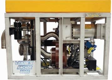
Vortex Anchor Boss Suction Pump Using the latest technology to reduce vessel time
The suction anchor system is a suction pump system that is designed to be mounted on the side, rear of the ROV or skid mounted.
The tool consists of the proven high flow vortex water pump, high flow suction and pressure relief valves, task specific water flow meter and Perry USD to display real time water flow and water pressure.
The anchor boss system is primarily used for suction pile / anchor installation and removal in addition to riser flushing applications where high water flow is required. The system uses the latest pump and flow technology which enables it to remain subsea for the duration of the pile installation. Other conventional systems require change out for low flow / high pressure pump which as a result increases vessel time.
Vortex Anchor Boss Suction Pump
Specifications
Minimum hydraulic pressure 60bar / 870psi
Maximum hydraulic pressure (Hyd motor)350bar / 5076psi
Maximum hydraulic flow 180lpm / 47.5gpm
Relief valve Adjustable from 0.3-8.0bar / 4.3-116psi
Maximum water flow 215m3 / hr with 180lpm / 47.5gpm at 248bar / 3596psi
Maximum pressure differential 9.5bar / 139psi
Connections 75mm / 3in ID hose
Weight in air 125kg / 275.5lbs
Materials Aluminium, stainless steel, thermoset epoxy resin
Pressure & hoses 2 x 2 JIC hoses
Case drain 1 x 6 JIC hose
Applications
Deploy large suction anchors
Recover large suction anchors
Features
High efficiency
High performance
Easily interfaced
Flow reversal for anchor recovery
Variable suction release valve
preset
Durable moving body design
In the box
Tritech AnchorZip10
50-75mm / 2-3in hose flange
Operational hoses
Operations and maintenance manual
Tritech AnchorZip 10
Heavy duty ROV suction anchor pump
The AnchorZip 10 is a heavy duty suction anchor pump designed for work vehicles able to produce 25 HP of hydraulic power.
The AnchorZip 10 is a unique product which incorporates many technical advances developed from several years of producing and operating Tritech’s industry-standard range of ROV mounted jetting and excavation systems.
The AnchorZip 10 is specifically designed for ROV deployment and will interface with most work ROV hydraulic systems. ROV fitted with the new AnchorZip 10 pump will offer a very quick and cost effective way of installing and removing suction anchors. Output pressures may be regulated to ensure that differential pressures remain within the structural limits of all types of suction anchor. Flow reversal for anchor recovery is cleverly and simply achieved by sliding the motor and top assembly from the input to the output side of the centrifugal pump.
Tritech AnchorZip 10
Specifications
Hydraulic motor pressure 276bar / 4000psi
Hydraulic motor flow 70lpm / 18.4gpm
Actuator minimum pressure 70bar / 1015psi
Actuator maximum pressure 240bar / 3480psi
Maximum output differential pressureUp to 9.5bar / 138psi
Maximum output suction flow Up to 80 cubic metres per hour at 7.5bar / 108psi
Weight in air 30kg / 66lbs
Weight in water 14kg / 31lbs
Materials Stainless steel, Nylacast, UHMWPE
Pressure & return
Case
Suction or blow
1 x 5m
4 x 4
6 JIC hose 12 JIC hose
medusa
JIC for cylinders
Applications
Pipeline / structure maintenance
Marine archaeology
Salvage operations
Features
Designed for depths of 600FSW
Air operated simplistic system
Proven reliability
Twin pot for continuous operation
Easy maintenance
Bespoke options
Specialist in-house design and fabrication capabilities and are able to modify any tool to suit client / project requirements.
UCS Subsea Grit Cleaning System
Diver operated grit cleaning system
The UCS subsea grit cleaning system is a low pressure air / grit entrained cleaning system suitable for cleaning operations down to a water depth of 600FSW (180mtr) which provides a fast, reliable and cost effective cleaning solution for removing marine growth, corrosion and other coatings to a S.A 2.5 finish. Continuous cleaning operations due to a twin grit pot design.
The system utilises air as the delivery system for the cleaning grit which can be supplied by either the vessel or a third party air compressor.
UCS Subsea Grit Cleaning System
Specifications
Grit consumption
Grit pot capacity
150kg / 331lbs/hr per hopper
250kg / 551lbs per hopper
Grit type ‘J-Blast’ Supa expandable abrasive - 0.2 -1.5mm
System rated pressure 27.6bar / 400psi
Compressor air flow
Air compressor requirements
Operational water depth
Typical cleaning rate
Dimensions
Gross weight
510 - 1444m³/hr / 300-850cfm
24bar @ 21m³/hr / 350psi @ 750cfm (Down to 152m)
24bar @ 24m³/hr / 350psi @ 850cfm heavy duty / high volume (Below 152m)
30-183m / 98-600ft (Refer to regulator depth pressure setting chart)
5m²/hr / 97in²/hr (Application dependent)
3340mm / 131.5in x 2420mm / 95.3in x 2740mm / 107.9in
8000kg / 17637lbs
Section 3 Cutters & grinders
01 Valve manipulation tools & accessories 02 Dredging & jetting 03 Cutters & grinders 04 Subsea pumping & injection 05 Topside pumps 03
Applications
Cutting of horizontal or vertical pipe, casings and structures
Features
Fast and accurate cut
2in to 56in capacity
Patented self-regulating feed
Superior performance
Simple operation
Diver or ROV operated
Compact design
Bespoke options
UCS have specialist in-house design and fabrication capabilities and able to modify any tool to suit client / project requirements
UCS Diamond Wire Saw
Diver or ROV operated diamond wire saw
The UCS diamond wire saws have been developed to cut tubulars ranging from 2in up to 56in.
The patented auto-feed system automatically regulates cutting progress, minimising the probability of broken wires. This has the advantage of removing human interference from the operation, assisting UCS Diamond Wires Saws in achieving world-leading cutting times.
Providing a fast and accurate cut, the diamond wire saw is especially good for cutting pipe in pipe, concrete filled multi-string bundles and coated products in both horizontal and vertical orientation.
Compact design enables easy installation and operation. This system can be supplied set up in a number of configurations to suit client project requirements.
 22"
42"
22"
42"
56" 305-1,422mm (12-56in)
80-90l/min / 21.1-23.8gal/min
42" 50-1,067mm (2-42in)
80-90l/min / 21.1-23.8gal/min
210bar / 3,045psi
ISO VG32 or equivalent 60mm/min (2.3in/min)
4-50mm/min (0.161.97in/min)
730kg / 1,609lbs
475kg / 1,047lbs
22" 50-558mm (2-22in)
60-70l/min / 15.9-18.5gal/min
210bar / 3,045psi
ISO VG32 or equivalent 60mm/min (2.3in/min)
4-50mm/min (0.16-1.97in/min)
570kg / 1,257lbs
373kg / 822 lbs
210bar / 3,045psi
11" 50-279.4mm (2-11in)
50-60l/min / 13.2-15.9gal/min
210bar / 3,045psi
ISO VG32 or equivalent 60mm/min (2.3in/min)
4-50mm/min (0.16-1.97in/min)
269kg / 593lbs
185kg / 408lbs
Hydraulic flow rate
Hydraulic requirements
ISO VG32 or equivalent 60mm/min (2.3in/min)
4-50mm/min (0.16-1.97in/min)
88kg / 194lbs
53kg / 117lbs
381mm / 15in
460mm
UCS
Diamond Wire Saw Specifications
cutting
Mass in air Mass in water
Cutting capacity Hydraulic oil type Maximum carriage speed Typical
speed
(X)
Jaw width open (J) Width
Height (Y) Depth (Z) 644mm
25.3in 785mm / 30.9in
/
/ 18.1in
Applications
Cutting of horizontal or vertical pipe, casings and structures
Features
Lightweight aluminium plate construction
Five models cut from 4in to 84in O.D. (DN100-2100)
Easily replaceable long life diamond wire cutting element Hydraulically operated synchronised clamping arms
Self adjusting automatic feed system
Overload clutch for bow damage prevention
Corrosion resistant with anode protection
Mounts vertically or horizontally In the box
Diamond Wire Saw Operations and maintenance manual
Wachs Diamond Wire Saw Subsea hydraulic diamond wire saw
Running on hydraulic power, the wire saw is controlled remotely using the Topside Control Panel (TCP), HPU with integrated TCP or by ROV control operable via zero leak hot stabs.
Wachs Diamond Wire Saws feature a unique hydrodynamic design that dramatically reduces centrifugal forces during operation, which means less power wasted in churning water and more power directed to cutting the work piece.
The Wachs Diamond Wire Saw features a unique self-adjusting auto feed system that controls wire bend and automatically matches the feed rate to the cutting rate. With the ability to adjust the feed until the cutting action catches up, Wachs DWS delivers more efficient cutting action with enhanced operator safety and greatly extended wire life.
In addition, the saw is equipped with a fully adjustable power clamping system, designed to grasp the work piece more accurately with fewer contact pads. It features two synchronised hydraulically actuated clamping arms that pivot inward, providing easy and secure remote control mounting. Synchronised clamping arms ensure uniform, square and secure mounting and prevent damage to the arms from unequal forces. Because the machine mounts more accurately, less visual supervision is required.
Wachs Diamond Wire Saw Specifications
System function
System capacity
Cutting wire
Cutting wire speed
Drive options
Power requirements
Feed method
Feed rate
Construction
Finish
Clamping pads
Wire guides
Designed to cut submerged pipe, casing and structure of varying materials and thicknesses using a high speed rotating diamond wire loop cutting element
Five models designed to cut from 4in to 84in O.D. (DN100-2100)
Quick change continuous loop diamond wire cutting element
Variable, 0-1,500rpm
Hydraulic only
20gpm @ 2500psi (76lpm @ 172bar) varies by model and application
Automatic self-adjusting feed control with screw drive and manual override
Variable based on workpiece material and density
Lightweight aluminum plate construction, constant tension bow feed, three hydraulic drive circuits - cutting, feed, and clamp drive.
Corrosion resistant powder coated aluminum frame plates, black anodised aluminium select components, and stainless steel hardware
User replaceable crush resistant urethane clamping pads
User replaceable durable urethane inserts
Model numberDWS 1604DWS 3012DWS 3616DWS 5230DWS 8460
Max pipe capacity16in (406mm)30in (762mm)36in (914mm)52in (1321mm)84in (2134mm)
Min pipe capacity4in (102mm)12in (305mm)16in (406mm)30in (762mm)60in (1524mm)
Height55in (1397mm)82.5in (2096mm)92.5in (2350mm)127in (3226mm)205in (5207mm)
Width 44in (1118mm)63.75in (1619mm)69.75in (1772mm)87.25in (2216mm)118.8in (3017mm)
Depth 28in (711mm)30in (762mm)32in (813mm)43in (1092mm)43in (1092mm)
Weight730lbs (331kg)1000lbs (454kg)1200lbs (544kg)1600lbs (726kg) Call
Product part no.10-010-51610-010-53010-010-53610-010-55210-010-584
Replacement wire09-071-71008-011-71008-051-71008-021-71008-031-710
Applications
Demolition cutting
Cutting various subsea products
Features
Fast destruction cut
Superior performance
User friendly
High volume cut rate
Bespoke blade options available
Shear Cutter
Hydraulic shears for demolition cutting
Engineered for maximum performance, Ashtead Technology’s range of Shear Cutters deliver high-volume scrap cuts on a wide variety of structures and materials, including umbilicals, flexible/rigid pipes, I/H beams, channel iron, steel plate, wire, re-bar and concrete.
The Shear Cutters are equipped with various padeyes, providing a variety of possible lifting configurations and great versatility in potential cutting angles. In addition to user-friendly controls, these Shear Cutters only require a 350 bar Hydraulic Power Unit (HPU) and a twin-line hydraulic umbilical.
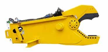
Ø36" x 1736Te
Ø 28 " x 1654 Te
36in 1736 1890 95 litre 18,000kg
Ø 22 " x 948Te
28 in 1654 1819 63.5 litre 8,000kg
22 in 948 1043 57 litre 4,450kg
Shear Cutter Specifications Ø Te @ 350 bar Oil tank capacity min Te @ 380 bar Weight
Applications
Wire rope cutting
Cable cutting
Umbilical cutting
Features
Heavy duty wire rope cutter
Hydraulically operated anvil
Robust stainless steel construction
Long blade life
Can be used at any water depth
In the box
Operational hoses
Operations and maintenance manual
Webtool HCV270 & HCV330 Wire Rope Cutter
Heavy duty cable, umbilical and riser cutter
The HCV cutters are heavy duty wire cutter's designed for cables, hydraulic lines, risers and umbilicals. The cutter's can be used either deck mounted or subsea with a work class ROV.
Corrosion resistant and durable coated steel and stainless steel construction. Genuine WebtoolTM blades and anvils give optimum cutting performance and ensure that maintenance is kept to a minimum. Hydraulically-operated anvil makes capturing and severing of the wire rope simple.
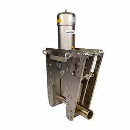
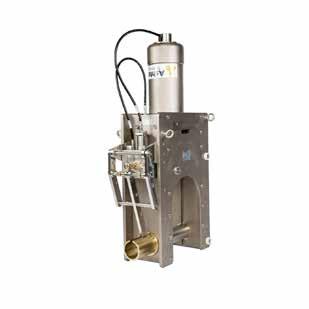
HCV330
HCV270
Webtool HCV270 & HCV330 Wire
Rope Cutter
Specification
Maximum
HCV270
Maximum 270mm / 10.6in
HCV330
Maximum 330mm / 13.0in Maximum
690bar / 10,000psi
/ 10,000psi Maximum
210bar / 3,045psi
352kg
324kg
1,143mm / 45in
883mm / 34.75in
/ 3,045psi
/ 56.1in
/ 40.1in Depth
Intensifier panel
Host connections anvil
278mm / 11in
Optional
1 x 10k 4 JIC (extend) 1 x 4 JIC (return)
2 x 4 JIC
2 x 4 JIC
/ 12.5in
cutting capacity
input pressure (main
690bar
input pressure (anvil) 210bar
Weight in air 552kg
in water 478kg
1,425mm
1,019mm
Built
connections main
cylinder)
Weight
Height
Width
in Hose
cylinder 2 x 4 JIC
318mm
Applications
Wire rope cutting
Cable cutting
Umbilical cutting
Features
Heavy duty wire rope cutter
Hydraulically operated anvil
Robust stainless steel
Construction long blade life
Optional intensifier panel is available
Can be used at any water depth
ROV mounting bracket (optional)
Deployed by crane or ROV
In the box
RCV Cutter
Operational hoses
Operations and maintenance manual
Webtool RCV115, RCV135 & RCV155 Wire Rope Cutter
Heavy duty wire rope cutter for subsea deployment
The RCV cutter's are heavy duty wire rope cutter's designed for subsea deployment in severe working conditions. The integrated hydraulic anvil removes the need for diver intervention and makes the tool easily deployed and operated by ROV.
Corrosion resistant and durable coated steel and stainless steel construction. Genuine Webtool™ blades and anvils give optimum cutting performance and ensure that maintenance is kept to a minimum. Hydraulically operated anvil makes capturing and severing of the wire rope simple.
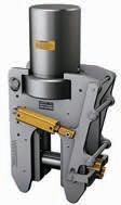
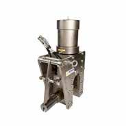
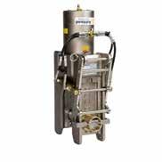 RCV115
RCV135
RCV155
RCV115
RCV135
RCV155
Webtool RCV115, RCV135 & RCV155 Wire Rope Cutter
Specifications
Maximum cutting capacity
RCV115
Maximum Ø115mm
Max input pressure (main cylinder) 690bar / 10,000psi
Max input pressure (anvil)
210bar / 3045psi
Weight in air 125kg
Weight in water 100kg
Height 700mm / 27.5i
Width 511mm / 20in Extend/retract Anvil
RCV135
Maximum Ø135mm
690bar / 10,000psi
210bar / 3045psi
176kg
152kg
794mm / 31.25i
569mm / 22.4in
2 x 4 JIC
2 x 4 JIC
RCV155
Maximum Ø155mm
690bar / 10,000psi
210bar / 3045psi
241kg
208kg
867mm / 31.25i
592mm / 31.25i
2 x 4 JIC
2 x 4 JIC
2
2
open/close
x 4 JIC
x 4 JIC
Applications
Wire rope cutting
Cable cutting
Umbilical cutting
Features
Heavy duty wire rope cutter
Hydraulically operated anvil
Lightweight aluminium construction
Long blade life
Ideal for use in confined spaces
Integrated interlock ensures that the blade cannot activate until the anvil is fully deployed
Integrated hydraulic intensifier and internal relief valve
In the box
RCV75HD Cutter
ROV handle
Operational hoses
Operations and maintenance manual
Webtool RCV75HD Wire Rope Cutter
Heavy duty wire rope cutter
The RCV75HD is a heavy duty wire rope cutter designed for subsea deployment in severe working conditions. Its lightweight and reliability make it a standard piece of tooling in many ROV fleets.
Lightweight aluminium and stainless steel construction. Hydraulically operated anvil makes the tool easy to operate and removes the need for diver intervention. Robust and durable. Genuine Webtool™ blades and anvils give optimum cutting performance and ensure that maintenance is kept to a minimum. Integrated interlock – The blade cannot activate until the anvil is fully closed, preventing accidental operation in low visibility environments. Integrated minibooster intensifier –The RCV75HD requires a low pressure hydraulic supply to operate. Integrated relief valve improves reliability and prevents accidental over-pressurisation of the cylinder.
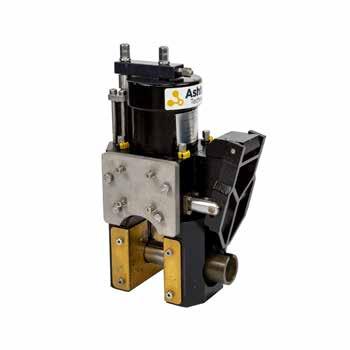
Webtool RCV75HD Wire Rope Cutter
Specifications
Cutting capacity
Maximum Ø75mm / 3in wire rope of 1960N/mm² grade
Maximum input pressure 210bar / 3045psi
Flow rate 4lpm / 1gpm to 14lpm / 3.7gpm
Fluid Compatible with ISO32 hydraulic oil
Weight in air 43kg / 94lbs
Weight in water 30.5kg / 67lbs
Extend/retract
Anvil open/close
Built in intensifier
2x 4JIC hoses
2x 4JIC hoses
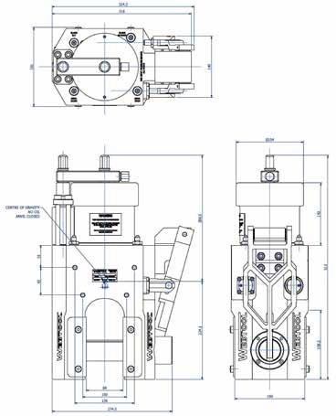
Applications
Wire rope cutting
Cable cutting
Umbilical cutting
Features
Max wire rope diameter 38mm / 1.5in
Cuts up to 1960N/mm² wire rope 22kg / 48.5lbs in air
In the box
RCO4OLP cutter with handle
Operational hoses
Operations and maintenance manual
Webtool RCO40LP Wire Rope Cutter
Low pressure heavy duty wire rope cutter
The RCO40LP is a low pressure heavy duty wire rope cutter designed for subsea deployment in severe working conditions. The open sided design allows for easy positioning on the wire by ROV while the blade shaped anvil increases the grade of rope that can be cut.
The open faced cutting tool has been designed specifically for cutting into long lengths of wire rope in a crisp and simple action. The shear power of the cutter makes it suitable for cutting wire rope, cables and umbilicals. Designed without the need for a separate anvil this open cutter is particularity useful in confined spaces.
The tool is engineered from the highest quality alloys and is polished and nickel plated for added corrosion protection. This high quality construction requires little or no maintenance throughout its operational lifetime. Replacing the cutting blade or seals are simple tasks.
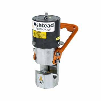
Webtool RCO40LP Wire Rope Cutter
Specifications
Cutting capacity
Steel wire ropes up to Ø38mm / Ø1.5in with a maximum tensile strength of 1960N/ mm²
Individual wire strands must be a minimum of Ø1.5mm / Ø0.05in
Maximum input pressure 220bar / 3190psi
Swept volume (Cut stroke) 0.5 litres / 0.13gal
Swept volume (Return stroke) 0.4 litres / 0.10gal
Hydraulic fluid
Mineral oil
Approx weight in air 22kg / 48.5lbs
Approx weight in water 19kg / 42lbs
Extend/retract 2 x 4 JIC
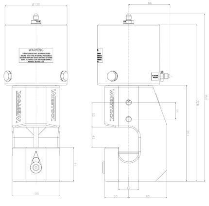
Applications
Softline cutting
Fibre rope cutting
Features
Hydraulically operated
Aluminium and stainless steel
Diver or ROV operable design
Quick and efficient operation
Long blade life
In the box
Softline cutter
ROV handle
Operational hoses
Operations and maintenance
manual
Webtool SL55, SL75 & SL135 Softline Cutter
Heavy duty softline cutter for subsea deployment
The softline cutter's are a lightweight but heavy duty softline cutter designed for subsea deployment in severe working conditions. The open sided design allows for easy positioning on the line by ROV or diver and simple operation. The design permits fast and efficient cutting of soft lines and fibre ropes.
Corrosion resistant and durable coated aluminium and stainless steel construction. Genuine Webtool™ blades and anvils give optimum cutting performance and ensure that maintenance is kept to a minimum. The softline cutter’s open sided design and no moving anvil makes deployment simple and reduces the number of hydraulic hoses required. The compact design is ideal for operation in confined spaces or where access is limited.
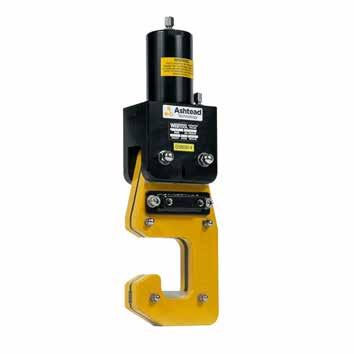
Webtool SL55, SL75 & SL135
Softline Cutter Specifications
SL55
Cutting capacity
Maximum Ø55mm Ø2.1in fibre rope
Maximum operating pressure 210bar (3045psi)
Weight in air 10kg
Weight in water 7kg
Height 487mm (19in)
Width 155mm (6.1in)
Hydraulic connections 2 x 4 JIC hoses
SL75
Maximum Ø75mm Ø3in fibre rope
210bar (3045psi)
23.5kg
16kg
532mm (21in)
210mm (8in)
2 x 4 JIC hoses
SL135
Maximum Ø135mm Ø5.3in fibre rope
690bar (10,000psi)
34.5kg
23.5kg
927mm (36.5in)
300mm (12in)
2 x 10K psi 4 JIC hoses
Applications
Linear cutting on horizontal or vertical pipe, casings and structures
Versatile bespoke cutting solutions
Features
Fast and accurate cut
Easy installation
Up to 13in deep cuts
Superior performance
Adaptable utilisation
Tungsten carbide tipped (TCT) blade
Depth control
Bespoke options
Specialist in-house design and fabrication capabilities and able to modify any tool to suit client / project requirements.
UCS Linear Track Saw
Diver or ROV operated linear track saw
Engineered to perform cuts up to 13” deep, the UCS Linear Track Saw provides a rapid, accurate and clean cut thanks to its Tungsten Carbide Tipped (TCT) blade. The Linear Track Saw features an adjustable cutting depth and can effectively cut through abrasive coatings as well as steel.
With impressive versatility as standard thanks to its slim size, the fastening brackets can be changed to fix to flat surfaces or fasten around a tubular structure or chains. A continuous straight cut can also be performed by joining the tracks together if required.
The UCS Linear Track Saw can be mounted upon a circumferential chain manipulator to perform a window cut of the desired size, when both linear and
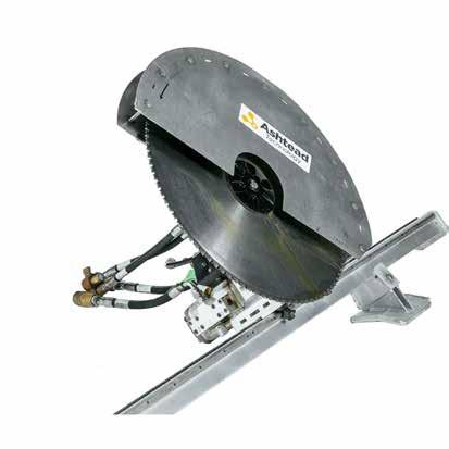
UCS Linear Track Saw
Specifications
Cutting capacity
Hydraulic requirements
Up to 300mm / 11.8in
65lpm @ 230bar / 14.3gpm @ 3336psi
Hydraulic oil type ISO VG32 or equivalent
Maximum carriage speed
Typical cutting speed
Mass in air (without track)
Mass in water (without track)
Blade speed
Dimensions
60mm/min / 2.3in/min
40-60mm/min / 1.6-2.4in/min
27kg / 59.5lbs
27kg / 59.5lbs
Variable to 1400rpm
685mm / 27in x 479mm / 18.9in x 423mm / 16.6in
Applications
Cutting of horizontal or vertical pipe, casing and structures
Features
Slim line design
4in-13in capacity
Proven reliability
Superior performance
Fast accurate cut
Diver or ROV Operation
Heavy-duty tungsten carbide tipped (TCT) chop saw blades
Solenoid control system for topside control
Bespoke options
Specialist in-house design and fabrication capabilities and are able to modify any tool to suit client / project requirements.
UCS Circular Chop Saw
Diver or ROV operated circular chop saw
The UCS Circular Chop Saw has been developed to cut tubulars up to 13” in diameter. With a powerful Tungsten Carbide Tipped (TCT) blade, this chop saw cleanly cuts through abrasive coatings as well as steel pipe. Its slim design allows it to be utilised in tight environments.
The system can be supplied with diver-operated control handles or with hot stabs and grab arm for control via ROV. Compact design enables easy installation and operation. This system can be supplied in a number of configurations to suit client and project requirements.
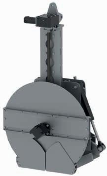
UCS Circular Chop Saw
Specifications
Cutting capacity
Hydraulic requirements
Hydraulic oil type
Maximum carriage speed
Typical cutting speed
Mass in air
Mass in water
Jaw width open
Dimensions
330mm / 13in
40-55lpm @ 210bar / 8.8-12gal @ 3045psi
ISO VG32 or equivalent
60mm/min / 2.3in/min
10-40mm/min / 2.3in/min
200kg / 440lbs
150kg / 330lbs
964mm / 38in
1610mm / 63.4in x 934mm / 36.8in x 590mm / 23.2in
Applications
Cutting operations
Features
400mm / 16in cutting disc
3 position handle for ease of operation
In the box
Super Grinder
Spin down block
Supply and return hoses
2 off cutting discs
Operations and maintenance
manual
Operational hoses
Ashtead Technology Super Grinder
Portable cutting tool designed for diver or ROV use
The Super Grinder is a portable tool, designed for use by a diver or ROV. It is primarily used for cutting operations, but can also be fitted with a variety of suitable grinding, abrasive and polishing discs
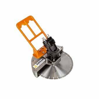
Ashtead Technology Super Grinder
Specifications
Maximum speed 2,700rpm
Maximum required flow 60lpm / 16gpm
Pressure 206bar / 3,000psi
Weight in air 21.2kg / 46.7lbs
Disc capacity 400mm / 16in max (25mm / 1in arbour)
Pressure and return 8 JIC hoses R
Connecting grinder to manifold 1 x JIC hose
Case to manifold 1 x JIC hose
4 x 8 JIC female hoses, 4m 1 x 6 JIC female hoses, 4m
Applications
Dyneema rope cutting
Hydraulic hose cutting
Cable cutting
Steel pipe cutting
Anchor chain cutting
Features
Can be used in air
Full grab or half blade cutter
Unrestricted operating depth
No coupling compensator required
Multiple blade options
In the box
Vortex Multi Cutter
Blades on request TCT, diamond, serrated
Operational hoses
Operations and maintenance manual
8 hoses come pre-installed
Vortex Multi Cutter Will cut almost anything
Vortex multi cutter is a flexible hydraulic cutter. This cutter stands out from many others in the market as it comes with multiple blade options, making it suitable for cutting a wide range of materials from steel pipe (up to 150mm), steel wire rope (up to 75mm), fibre rope (up to 160mm), casing, dyneema and aluminium to mooring lines (up to 160mm), dredge hose (up to 150mm diameter) and hydraulic hose etc.
Can be used as a full grab cutter or a basic half blade cutter, with or without grab handles, and can also be operated in air. It is powered by the proven Vortex dredge motor / mechanical sealing system for continued, oil tight reliability.
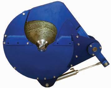
Vortex Multi Cutter
Specifications
Cutter hydraulic flow 20lpm / 5gpm minimum 50lpm / 13gpm maximum
Cutter hydraulic pressure 103bar / 1500psi minimum 241bar / 3500psi maximum
Grab Arm hydraulic pressure 14bar / 200psi minimum 69bar / 1000psi maximum
Valves Overrun valve, direction valve as standard
Coupling compensator No
Operating depth
Unrestricted
Depth of cut with 400mm / 16in blade130mm / 5in
Operation options
Full grab cutter or basic half blade cutter
Full grab tool weight in air 30kg / 66lbs
Half blade tool weight in air 24kg / 53lbs
Pressure & return
Case
Open and close
2 x 8 JIC female hoses
1 x 6 JIC female hoses, 4m
2 x 4 JIC female hoses, 4m
Applications
Anchor chain cutting
Wire rope cutting
Drill string cutting
Steel pipe cutting
Coflexip cutting
Features
Integrates with any manipulator
In the box
Manipulator Saw
Adaptor plate
Tungsten carbide blade
Control panel
Operational hoses
Operations and maintenance manual
Manipulator Mounted Saw
Designed to mount on any manipulator wrist
Using a 14” tungsten carbide saw blade the manipulator mounted saw cuts through a multitude of materials with absolute ease and dexterity.
Specially designed to mount on the Schilling Rigmaster, using adaptor plates, the material to cut is simply grabbed with the manipulators jaws, held in place and cut.
Designed to fit to, rather than being held by the manipulator retains full function of the manipulators movements for further subsea tasks without limitation. Once a material is located in position the blade is switched on and fed towards the material, on completion of a cut the blade retreats within the saws body protecting it and the manipulator from entanglement or obstruction and allows the next target to be located in moments.
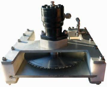
Manipulator Mounted Saw
Specifications
Hydraulic input pressure
Flow
Maximum cutting distance
Blade diameter
Maximum intermit speed
Approx weight in air
Approx weight in water
Pressure & return
Case extend & retract
140-210bar / 2030-3045psi
40lpm / 10.5gpm
93mm / 3.6in
350mm / 13.7in
600rpm
32.1kg / 70.7lbs
22.4kg / 49.3lbs
2 x JIC female swivel, 4m
4 x 4 JIC female swivel, 4m
Applications
Riser cutting
Guide post cutting
Chain cutting
Features
Performance tungsten carbide blade
Lightweight aluminium construction
Variable cutting speed
Interlocking clamps
In the box
10” Rotary Cutter
700mm / 27.5in high performance blade
Operational hoses
Operations and maintenance manual
10” Rotary Cutter Clamps to structures between 3” and 10” diameter
The 10” rotary cutter has been designed to clamp on to structures and cut material up to 10 inches in diameter, using the standard high quality tungsten carbide tipped blades to cut ferrous and non-ferrous metals easily including high tensile steels.
The cutter consists of an aluminium assembly, a clamp arrangement which is actuated by two rams to enable secure clamping on to structures more than 3” diameter and up to 10” diameter. The main motor is mounted on a vertical slide to extend and retract the position of the blade. A counter-balance valve is set to stop the
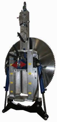
10” Rotary Cutter Specifications
Main motor pressure
Main motor flow
Clamp pressure
140-180bar / 2030-2610psi
40-60lpm / 10.5-15.8gpm
50-100bar / 725-1450psi
Clamp flow 1-5lpm / 0.2-1.3gpm
Extend cylinder pressure
Extend cylinder flow
20-100bar / 290-1450psi
0.1lpm / 0.02gpm
Pressure & return 2 x 8 JIC female, 5m
Applications
Cutting of umbilicals
Salvage operations
Inspection support
Features
Fast and accurate cut
4in to 30in capacity
Patented cutting technique
Superior performance
30mm coupon removed for inspection
Heavy-duty band saw blades
Bespoke options
UCS have specialist in-house design and fabrication capabilities and are able to modify any tool to suit client / project requirements.
UCS Dual Cut Band Saw
Diver or ROV operated dual cut band saw
The patented dual cut band saw is designed to cut through a range of materials of various diameters from 4-30in using a single saw unit.
The precision dual cut provides a 30mm wide coupon that can be returned to surface for inspection.
The reaction loads generated by each of the simultaneous cuts are cancelled out, resulting in a very smooth, vibration free and reliable cut. On completion of the cut, the 30mm wide ‘coupon’ falls out, leaving a gap between the two ends of the pipe for ease of recovery of the cut section.
Providing a fast and accurate cut, the dual cut band saw is especially good for cutting pipe in pipe, concrete filled multi-string bundles and coated products in both horizontal and vertical orientation.
Compact design enables easy installation and operation. This system can be supplied set up in a number of configurations to suit client project requirements.
UCS Dual Cut Band Saw
Specifications
Cutting capacity
Hydraulic requirements
Hydraulic oil type
Maximum carriage speed
Typical cutting speed
Mass in air
Mass in water
Jaw width open
Dimensions
100-762mm / 4-30in
40-50lpm @ 210bar / 8.8-11gal @ 3045psi
ISO VG32 or equivalent
60mm/min / 2.3in/min
4-20 mm/min / 0.157-0.79in/min
250kg / 551lbs
200kg / 440lbs (buoyancy optional)
964mm / 38in
2477mm / 97.5in x 576mm / 22.7in x 1905mm / 75in
Applications
Cutting where structural compression is present
Cutting of complex shapes for crack mitigation on structures
Salvage operations
Features
Cutting pressure
5,000psi-15,000psi
Internal and external cutting
Minimal maintenance required
Adaptive bespoke tooling to suit client requirements
Operator friendly
Lloyds Register Certified to PED 97/23/EC (CATII)
Comes with pressure relief valve and burst discs
Bespoke options
UCS have specialist in-house design and fabrication capabilities and are able to modify any tool to suit client / project requirements.
UCS Abrasive Waterjet Cutting System
Internal and external cutting system
The UCS abrasive waterjet cutting system has been specifically designed to reduce the amount of deck space required along with being harmless to the marine environment. Great care has been taken in the construction of the jet cut system to reduce moving parts and troublesome valves, thus creating an extremely efficient and reliable system with minimal maintenance and break down time.
The system can operate between 5,000psi-15,000psi, product and surface dictating pressures required. The system is used to deliver a consistent water/ garnet mix to project specific manipulators. Standard manipulators are used for internal and external cutting as well as bespoke tooling available for specific profile cuts.
Safety features include specially designed pressure vessels, built in line with PD5500-2006 and PED 97/23/EC and certified by Lloyd’s Register Group Limited to ensure compliance with relevant legislations.
UCS Abrasive Waterjet Cutting System
Specifications
Pressure rating Up to 1000bar / 15,000psi
Grit capacity 2 x 66ltr / 2 x 17.4gal
Water connection ¾in bsp
Surry connection ¾in bsp
Mass 4560kg / 1053lbs
Safety specification 490kg / 1080lbs
Mass in water Lloyds Register certified to PED 97/23/EC (CATII)
Dimensions 2391mm / 94.1in x 1700mm / 66.9in x 3318mm / 130.6in
Options
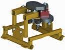 Optional UCS Mooring Chain Cutter
Optional UCS Circumferential Chain Manipulator
Optional UCS Internal Pipe Cutter
Optional UCS Abrasive Hole Cutter
Optional UCS Mooring Chain Cutter
Optional UCS Circumferential Chain Manipulator
Optional UCS Internal Pipe Cutter
Optional UCS Abrasive Hole Cutter
Applications
Drain and vent holes for recovering ballasts on towheads, MWA etc Tie down or magnet fitments Salvage operations
Features
Fast and accurate cut
From Ø160mm
Simple operation
Diver or ROV operated
Compact design
Bespoke options
UCS have specialist in-house design and fabrication capabilities and are able to modify any tool to suit client / project requirements.
UCS Abrasive Hole Cutter
Multi diameter hole cutter
The UCS abrasive hole cutter utilises diver or ROV operated magnets or manual tie backs to secure the tool to the surface which requires a hole to be cut.
The nozzle can be extended out from the centre axis to give a minimum hole of Ø160mm up to Ø500mm. UCS can also offer a bespoke version for greater diameters if required.
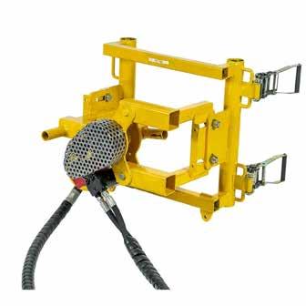
UCS Abrasive Hole Cutter
Specifications
Hole cutting capacity
Pipe Ø200mm / 8in to unlimited
Hydraulic requirements Up to 22lpm @ 210bar / 5.8gpm @ 3045psi
Hydraulic oil type ISO VG32 or equivalent
Typical cutting speed
Mass in air
Mass in water
Dimensions
4-100mm/min / 0.16-4in/min
50kg / 110.2lbs
46kg / 101.4lbs
451mm / 17.8in x 609mm / 24in x 634mm / 25in
Applications
Compression pipe cutting
Depth controlled cutting
Cleaning for surveying / inspection
Salvage operations
Features
Abrasive nozzle option
High pressure cleaning head option
Track saw option
Minimal maintenance required
Adaptive bespoke tooling to suit client requirements
Operator friendly
Bespoke options
UCS have specialist in-house design and fabrication capabilities and are able to modify any tool to suit client / project requirements.
UCS Circumferential Chain Manipulator
Diver operated multi-function tool
The standard circumferential chain manipulator (CCM) is ideal for externally cutting all types of round products.
The CCM can be fitted with a number of options including an abrasive waterjet cutting nozzle, track saw blade or a high pressure jetting head for coating removal.
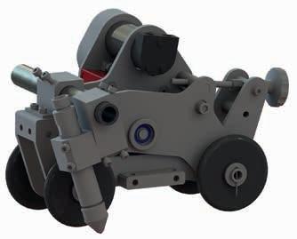
UCS Circumferential Chain
Manipulator
Specifications
Cutting capacity
Hydraulic requirements
Pipe Ø200mm / 8in to unlimited
22lpm @ 210bar / 5.8gpm @ 3045psi
Hydraulic oil type ISO VG32 or equivalent
Typical cutting speed
Mass in air
Mass in water
Dimensions
Options
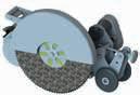
Optional UCS Circumferential Track Saw
4-100mm/min / 0.16-4in/min
28kg / 61.7lbs
24kg / 52.9lbs
476mm / 18.7 x 266mm / 10.5in x 270mm / 10.6in
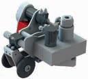
Optional UCS Circumferential Cleaning Tool
Applications
Drilling of holes through horizontal or vertical pipes, casings and structures including multistrings
Features
Fast and accurate drill
Easy installation
Drills up to 39” pipes
Superior performance
Adaptable utilisation
Bespoke options
UCS have specialist in-house design and fabrication capabilities and are able to modify any tool to suit client / project requirements.
UCS Clamping Drill Machine
Developed to drill through pipes and structures
The UCS clamping drill machine has been developed to drill through pipes with a maximum diameter of 39”. The unit is able to drill through typical pipes and structures made for the oil & gas industry.The CDM is designed to be operated by divers or remotely operated vehicles (ROV) and is not limited by water depth. It can be configured for hydraulic motor feed or manual control by diver. This unit is hydraulically driven and deployed to the seabed/cutting location by vessel crane when diver operated. Power is supplied from surface through a hydraulic hose umbilical.
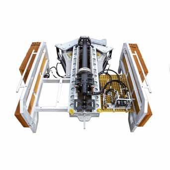
UCS Clamping Drill Machine
Specifications
Hydraulic system requirements
Drill motor maximum
70lpm / 17-19gpm @210bar / 3045psi
60lpm / 15-16gpm @80bar / 1160psi
Hydraulic oil type ISO VG32 or equivalent
Jaw width open
1108mm / 43in
Cutting stroke 1000mm / 39in
Hole size
100mm / 4in
Mass in air (without buoyancy) 448kg / 987lbs
Mass in water (with buoyancy)
Dimensions (without buoyancy)
Dimensions (with buoyancy)
20kg + 5kg / 44.1lbs +11lbs
1394.4mm / 54.9in x 800.3mm / 31.5in x 2250.5mm / 88.6in
2337mm / 92.1in x 852mm / 33.5in x 2295mm / 90in
Applications
Drilling operations
Features
Fast and accurate cut
Cuts up to 250mm / 10in
Easily installed
Diver friendly
Proven reliability
Superior performance
Bespoke options
UCS have specialist in-house design and fabrication capabilities and are able to modify any tool to suit client / project requirements.
UCS Hydraulic Pedestal Drill
Diver or ROV operated hydraulic pedestal drill
The UCS hydraulic subsea pedestal drill has been developed to cut up 250mm / 10in diameter holes and has a travel of 160mm / 6in. The chuck can be fitted with either rotor broaches or twist drills. It includes a chain strap fastener which allows easy installation to pipelines, piles or any structure that the chain can be wrapped around. The chains are supplied a custom length to suit the requirements of the job.
An alternate base can be fitted to perform cuts on flat surfaces, or diver / ROV magnets can be supplied.
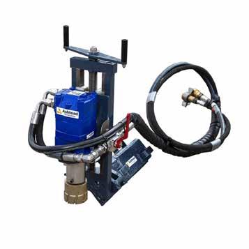
UCS Hydraulic Pedestal Drill
Specifications
Cutting capacity
250mm / 10in
Spindle speed Up to 275rpm
Slide travel
Hydraulic requirement
Hydraulic oil type
Mass in air
Chain length
Dimensions
160mm / 6in
35-45lpm / 9.25-11.9gpm
210bar / 3045psi
ISO VG32 or equivalent
30kg / 66.12lbs (without chain)
Custom
541mm / 21.3in x 299mm / 11.8in x 578mm / 22.8in
Stanley GR29 Underwater Grinder
For grinding and cleaning underwater applications
The Stanley hydraulic GR29 grinder is a right angle grinder (“vertical grinder”) that can be used for grinding, cutting and cleaning in underwater applications with a variety of wheels, brushes and attachments.
Applications
Marine growth cleaning
Grinding & cutting
Features
Integral Stanley Hyrevz gear motor
Stainless steel spools and fasteners
Two position assist handle for right/left hand operation
Oversized trigger with guard for diver comfort
Adjustable wheel guard for infinite positions
Plastisol covered handle for comfortable ergonomic grip
Use with grinding wheels, hull scrubbing brushes, wire and nylon brushes, barnacle busters and Desmond wheels
3200rpm @ 45lpm / 12gpm
Cast-in lifting eye
In the box
Stanley GR29 Underwater Grinder
ROV handle
Pin spanner
Operational hoses
Operations and maintenance manual
Stanley GR29 Underwater Grinder
Specifications
Capacity
230mm / 9in wheel
Spindle 5⁄8” - 11 threaded
Circuit type Open center
Flow range
Working pressure
Full relief setting
RPM
Weight (with guard)
Length
Width (with guard)
Hydraulic ports
Pressure & return
15-45lpm / 4-12gpm
70-140bar / 1000-2000psi
155bar / 2250psi
3200rpm at 45lpm / 12gpm
6.8kg /15lbs
280mm / 11in
260mm / 10.25in
-8 SAE o-ring 2 x 8 JIC female hoses, 4m
Applications
Concrete breaking
Asphalt breaking
Small rock breaking
Rod driving
Coral removal
Features
T-Handle with large on/off trigger for precise control
Stainless steel spool and fasteners
Trouble free diaphragm accumulator provides additional blow energy and reduces recoil
Feathering on/off valve allows easy initial tool bit placement
Uses standard 11⁄8” x 6” hex shank tool bits
Four tie rod design for durability
Operates in any position
Modular design for ease of service
Latch retainer
In the box
Stanley BR67 Underwater Breaker
ROV handle
Moil point chisel
Narrow chisel
Wide chisel
Operational hoses
Operations and maintenance manual
Stanley BR67 Underwater Breaker
Medium to heavy duty underwater hydraulic breaker
The Stanley BR67 underwater breaker is for medium to heavy duty breaking of concrete and rocks as well as being suitable for tamping and rod driving. The BR67 has T-handle design with a large trigger for precise control, there is a diaphragm accumulator fitted which provides additional blow force.
The Stanley hydraulic underwater breaker BR67 has a feathering on/off valve which controls blow speed, making startup and initial underwater tool placement easy.
The BR67 underwater breaker is capable of handling considerable back pressure (250psi). This feature is particularly useful as using long hose lengths, which are typical in marine environments, can often lead to increased back pressure.
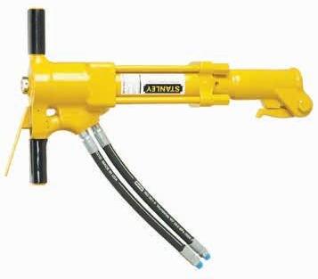
Stanley BR67 Underwater Breaker
Specifications
Performance
1300bpm @ 30lpm / 8gpm
Steel capacity 11⁄8” x 6” Hex
Handle type
Circuit type T-Handle Open center
Flow range
Optimum flow
Working pressure
Full relief setting
Weight (less tool bit)
Length
Width (at handles)
Hydraulic ports
26-34lpm / 7-9gpm
30lpm / 8gpm
105-140bar / 1500-2000psi
155bar / 2250psi
33kg / 73lbs
736mm / 29in
410mm / 16in
Pressure & return -8 SAE O-ring 2 x 8 JIC hoses, 4m
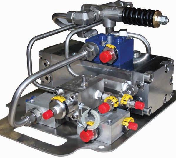
01 Valve manipulation tools & accessories 02 Dredging & jetting 03 Cutters & grinders
Subsea pumping & injection 05 Topside pumps 04
04
Section 4 Subsea pumping & injection
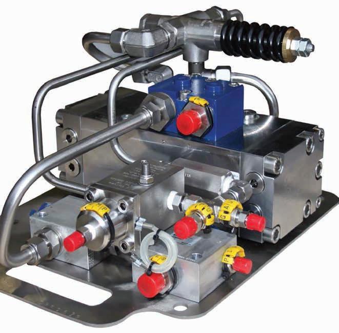
Applications
Pressure testing operations
BOP operations
Fluid transfer operations
Hot stab operations
Features
Isolated hydraulic power unit
Directional control
3 selectable pressures
690bar / 10,000psi max output
In the box
10,000psi IHPU
Test gauges
40ltr reservoir bag
Operational hoses
Operations and maintenance manual
10,000psi IHPU Multi-fluid injection system
The 10,000psi IHPU can be used for numerous subsea applications including pressure testing, BOP operation, fluid transfer and hot stab operations with the capability of directional control ranging from 1,150-10,000psi which can be operated proportionally.
Connection can be made to any sized fluid reservoir and operate using water / glycol and hydraulic mineral oils as suitable fluid media.
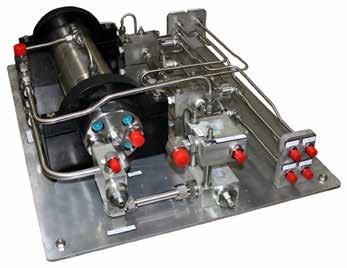
10,000psi IHPU
Specifications
Maximum input pressure 210bar / 3045psi
Maximum input flow 40lpm / 10.5gpm
Maximum output pressure 690bar / 10,000psi
Maximum output flow 9lpm / 2.3gpm
Fluids Water, glycol, hydraulic and mineral oils Weight
/ 137.7lbs
/
air
Weight in water 53.3kg
117.5lbs
pilot Dimensions Pressure / return Output Dump lines Gauge lines 610 x 465 x 242mm / 24 x 18.3 x 9.5in 8 JIC hose x 2 4 JIC hose 10K 4 JIC hose x 2 4 JIC hose x 2 10K 4 JIC hose x 3 c/w 15k gauges Suction Output pilot 8 JIC hose 4 JIC hose x 2
in
62.5kg
Pump
Applications
Pressure testing operations
Fluid transfer operations
Hot stab operations
Features
3 selectable pressures
Directional control
Suitable for mineral oils and glycols 350bar / 5076psi output
17lpm / 4.5gpm output
In the box
3 Stage IHPU
Test gauge
40ltr reservoir bag
Operational hoses
Operations & maintenance manual
3 Stage IHPU Multi-fluid injection system
The 3 Stage IHPU can be used for numerous subsea applications including pressure testing, BOP operation, fluid transfer and hot stab operations with the capability for 3 selectable pressures each ranging from 0-5000psi and is designed to be easily and simply reconfigured.
Connection can be made to any sized fluid reservoir and operate using water / glycol and hydraulic mineral oils as suitable fluid media. The inbuilt depressurisation
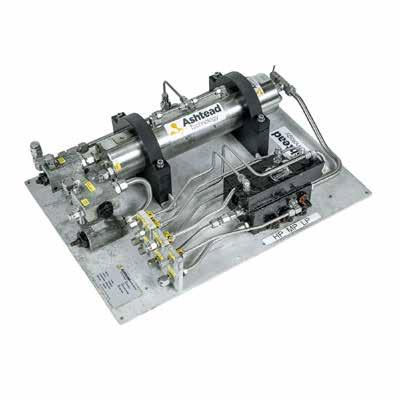
3 Stage IHPU Specifications
Hydraulic input pressure 210bar / 3045psi
Hydraulic input flow 35lpm / 9.2gpm
Hydraulic output pressure 350bar / 5076psi
Hydraulic output flow 17lpm / 4.5gpm
Fluids Seawater, glycol and mineral oils Weight
/ 128.5lbs
/
in air
Weight in water 48.4kg
106.7lbs Dimensions 650 x 465 x 185mm / 25.5 x 18.3 x 7.2in Pressure / return Directional control Output A+B 8 JIC hose x 2 4 JIC hose x 2 10K, 6 JIC hose, 6 JIC x 2 Tank Gauge ports Pilot Suction 6 JIC hose 4 JIC hose x 3 4 JIC hose 8 JIC hose
58.3kg
Applications
Pressure testing operations
Features
Manual pressure relief valve
Ram operated ball valve with reducing jet
Depth compensated pressure gauge
Electronic pressure transducer
Aluminium mounting plate
690bar / 10,000psi option available
In the box
Back seal test unit
Analogue gauge
Electrical cable for special TTCS
Operations and maintenance manual
Operational hoses
Back Seal Test Unit Pipeline pressure testing system
The BSTU provides a controllable pressure between 7 and 210bar to be applied via the pressure out connection. The pressure developed is monitored by a transducer which may be connected to the subsea control unit if required, and also an analogue subsea gauge. The applied pressure may be switched off / locked in by means of the ram operated ball valve.
All the components are mounted on an aluminium base plate which should be secured to the host vehicle structure in an accessible location. There are no specific spatial orientation requirements. Hydraulic connections are ¼” Swagelok male thread. The ram is operated by an ROV spare bi-directional function (210bar max). The supply pressure may be acquired anywhere suitable from the host vehicle circuit (210bar max). The drain line should be connected as directly as possible to the ROV return circuit to minimise return line losses.
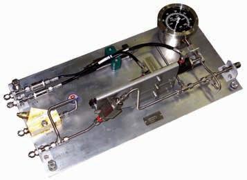
Back Seal Test Unit
Specifications
Hydraulic input pressure 210bar / 3045psi
Hydraulic input flow 15lpm / 3.9gpm
Hydraulic output pressure 7-210bar / 101.5-3045psi (adjustable)
Electrical output
Electrical connector
Open/close
Pressure in/out
Drain
4-20mA
Sub conn MCBH6M
4 JIC hose x 2
4 JIC hose x 2
4 JIC hose
Applications
Hot stab operations
ROV tooling operations
Features
210bar / 3045psi output
Directional control on output
Integrated filter unit
Input flow can be set depending on output required
Can be supplied as part of skid tooling package with reservoirs
Input PO check valve
Input flow control valve
Output pressure relief valve 40-275bar / 580-3988psi
Hydraulically piloted NG10 directional control valve on output
In the box
Isolated hydraulic power unit 2.7 litre / 0.71gal compensator
Header tank
Operational hoses
Operations and maintenance manual
Modular IHPU
Isolated hydraulic power unit
A high capacity intermediate hydraulic power unit designed to give isolated hydraulic power with directional control. The IHPU consists of a hydraulic motor equipped with a flow control and pilot to open check, which drives a hydraulic pump. The high pressure output of the pump is fed into a manifold that is equipped with a 20 micron filter, off load dump valve, a pressure relief valve, and a directional control valve.
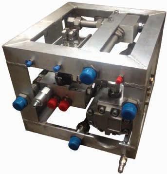
Modular IHPU
Specifications
Hydraulic input pressure
Hydraulic input flow
Hydraulic output pressure
Hydraulic input flow
Max output pressure with Intensifier
Fluids
Weight in air
Weight in water
Dimensions
Pump pilot
Pilot A&B
ROV pressure / return
Suction / return
Output A+B
Comp line
140-210bar / 2030-3045psi
20-150lpm / 5.2-39.6gpm
40-210bar / 580-3045psi
12-80lpm / 3.1-21.1gpm
690bar / 10,000psi
Hydraulic oil
61kg / 134.4lbs
47kg / 103.6lbs
430 x 390 x 330mm / 16.9 x 15.3 x 12.9in
4 JIC hose
4 JIC hose x 2
16 JIC hose x 2
16 JIC hose x 2
12 JIC hose x 2
8 JIC hose
Applications
Hot stab operations
ROV tooling operations
Features
Max output 690bar / 10,000psi (with intensifier)
Integral compensator
3 micron pressure filter
20 micron return filter
Relief valve
Hydraulic soft-start
Optional directional control valves
45kg / 99.2lbs in air
In the box
Isolated Hydraulic Power Unit
Operational hoses
Operations and maintenance manual
IHPU Dirty Work Pack
Isolated hydraulic power unit
Unit comes complete with hoses ready for integration to ROV system and can be used with or without directional control valve. 3 stage manifold blocks can be fitted underneath directional control valve making the unit ideal for applications needing three separate pressures i.e. torque tool operations. The system is supplied with full spares package including spare motor and pump and can be supplied to operate with glycol. Can be reconfigured to reach pressures of 10,000psi.
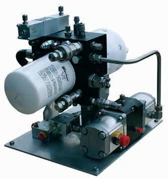
IHPU Dirty Work Pack
Specifications
Hydraulic input pressure
Hydraulic input flow
Hydraulic output pressure
Hydraulic input flow
Max output pressure with Intensifier
Weight in air
Dimensions
Pressure
Return
Pilot
DCV Pilots
Outputs
180-210bar / 2610-3045psi
45-60lpm / 11.8-15.8gpm
210bar / 3045psi
30lpm / 7.9gpm
690bar / 10,000psi
45kg / 99.2lbs
430 x 350 x 400mm / 16.9 x 13.7 x 15.7in
8 JIC hose
12 JIC hose
4 JIC hose
4 JIC hose x 2
4 JIC hose
2
x
Applications
BOP actuation operations
Features
300lpm / 79.2gpm output
Suitable for seawater, mineral oil and glycols
Can be combined with 400 litre / 105.6gal fluid reservoir skid
In the box
BOP-AT 300
2 x 200 litre reservoirs
Manipulator operated ball valve
Operational hoses
Operations and maintenance manual
Blow Out Preventer (BOP-AT 300) Blow out preventer actuating tool
When a problem occurs subsea and underground pressure forces oil or gas into the wellbore the blow out preventer (BOP) is required to operate quickly preventing damage to surface modules and the surrounding environment.
If the BOP cannot be operated remotely one of the few remaining options to actuate the BOP is by using ROV intervention. For this to occur quickly and safely the intervening ROV requires to deliver very high flow fluids at high pressure.
The blow out preventer actuating tool (BOP-AT) is designed to be operated by a workclass ROV, delivering 300lpm of fluid at pressures up to 1500psi.
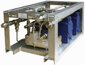
Blow Out Preventer (BOP-AT 300)
Specifications
Maximim input pressure
Maximum input flow
Maximum output pressure
Maximum output flow
Fluids
Options
Weight in air
Dimensions
Pressure & return
Output
Pilot
Dump
Gauge line
210bar / 3045psi
100-150lpm / 26.4-39.6gpm
510bar / 7396psi
300lpm / 79.2gpm
Seawater, mineral oil and water based glycol 400 litre / 150.6gal capacity skids
80kg / 176.3lbs
720 x 460 x 380mm / 28.3 x 18.1 x 14.9in
16 JIC x 2
16 JIC
4 JIC x 3
10K, 4 JIC x 1
10K, 4 JIC x 1
Applications
LAOT operations
Cutting operations
Features
Genuine mini-booster intensifier
Achieves pressures up to 690bar / 10,000psi
4:1 ratio as standard
Suitable for oil or glycols
Weighs less than 5kg / 11lbs in air
Mounted on ROV friendly plate
In the box
Multi-fluid Intensifier
Test gauge
Operational hoses
Operations and maintenance manual
Multi-fluid Intensifier
10,000psi multi-fluid pump
Multi-fluid Intensifier provides a multi-purpose high pressure intensifier circuit suitable for directly mounting onto a subsea skid or direct to an ROV.
Designed primarily for use with Shell Tellus 22 or 32 grade hydraulic oils, this intensifier can operate using hydraulic oil, glycol or a water/glycol mixture. The Intensifier should be completely flushed when reverting to hydraulic oils.
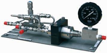
Multi-fluid Intensifier
Specifications
Hydraulic input pressure 207bar / 3,000psi
Hydraulic input flow 14lpm / 3.6gpm
Hydraulic output pressure 690bar / 10,000psi dependant on ratio
Fluids Oil, glycol and water-glycol mix
Weight in air 4.7kg / 10lbs
Weight in water 3.9kg / 8.5lbs
Dimensions 1 x 4JIC hose, 4m
310 x 135 x 120mm / 12 x 5 x 4.7in
Hoses
Applications
Diver cutting operations
Diver LAOT operations
Features
Rugged all metal construction
Heavy-duty, formed metal handle
Relief valve
Fitted with hydraulic compensator
Fitted with quick disconnects
Subsea pressure gauge
In the box
Power Team Hand Pump
Operational hoses
Operations and maintenance
manual
Ashtead Technology Hand Pump
Compensated hydraulic hand pump
The Power Team compensated hydraulic hand pump delivers hydraulic fluid under pressured by directly applied manual effort. Power Team hand pumps, with the angled fill port, have a built in “relief valve” protection system. This system is designed to protect over-pressurisation of the reservoir from sudden back pressure. This system also works as a seal to prevent oil leaks.
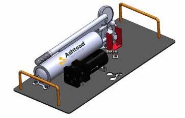
Ashtead Technology Hand Pump
Specifications
Maximum output pressure 690bar / 10,000psi
Volume per stroke 42.6cm3 (2.600in3)
Oil capacity 2,491cm3 (137in3)
Weight 22kg / 48.5lbs
Dimensions 700 x 450 x 200mm / 27.5 x 17.7 x 7.8in
Pressure return Pioneer QDs
Section 5 Topside Pumps
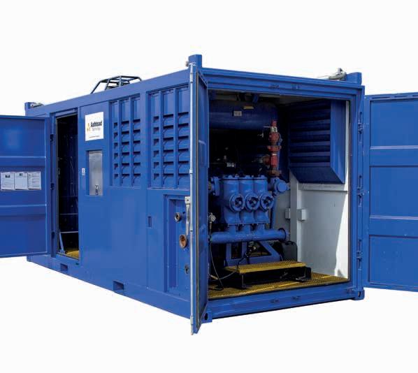
01 Valve manipulation tools & accessories 02 Dredging & jetting 03 Cutters & grinders
Subsea pumping & injection 05 Topside pumps 05
04
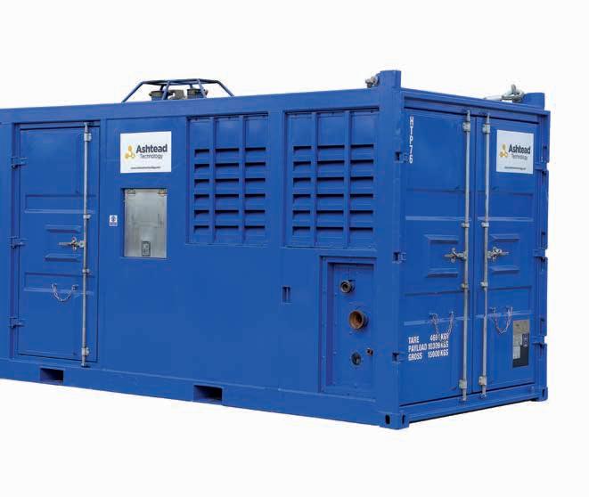
Applications
Petrochemical/hazardous & safe area/marine/civil
Features
Engine - Safe Area Volvo Diesel
Engine
Pump - RKB 200/37 - 5 stage
Battery start
Externally mounted control panel
DNV certified container package (16x8) & lifting arrangement 2.7-1
CE marked
In the box
Documentation packagemanuals & certification
Comprehensive critical spare parts package
Diesel Driven Centrifugal Pump Set (16x8) HTP38
Petrochemical/hazardous & safe area/marine/ civil
Ashtead Technology has a rental fleet of quality electric, hydraulic and diesel driven centrifugal pumps, covering various applications from 100 hp – 1000 hp. Whether it is a petrochemical Hazardous Area or Safe Area application, or a marine or civil engineering project, Ashtead Technology has a range of pumping equipment to choose from and can tailor solutions for your project requirements. With DNV 2.7-1, ATEX and CE Marking certifications, safety and reliability is guaranteed.
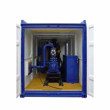
Diesel Driven Centrifugal Pump
Set (16x8) HTP38
Specifications
Volvo
Fuel type
Maximum RPM
Starting system
kW
Controls
Shut down systems
Pump type
Pump duty
Closed in discharge pressure
Standard connections
Diesel
1,800 rpm
Battery start
485 kW at 1800 rpm
Externally mounted control panel c/w all controls and gauges
Stop, emergency stop, overspeed, high water temp, low engine oil pressure, Chalwyn valve, spark arrestor fitted
227 m³/hr at 40 bar at 1800 rpm
500 m³/hr at 16 bar at 1800 rpm
8" 150 suct, 4" 300 or 4" 206 discharge
RKB 200/37 5 stage 15,500kg
Dimensions Height Length Width 2,830mm 4,877mm 2,438mm Maximum gross certified weight Actual shipping weight 10,600kg
Applications
Pumping water/mud/brine/ chemicals & crude oil
Features
Zone 1 certified
Hydraulic drive/supply - Bent -Axis type piston motor
Pump - Mug Hog 4x3x13
Centrifugal
DNV certified frame & lifting arrangement 2.7-1
ATEX compliant
CE marked
In the box
Documentation packagemanuals & certification
Comprehensive critical spare parts package
Zone 1 Hydraulic Driven Centrifugal Pump
Pumping water/mud/brine/chemicals & crude oil
Ashtead Technology has a rental fleet of quality electric, hydraulic and diesel driven centrifugal pumps, covering various applications from 100 hp – 1000 hp. Whether it is a petrochemical Hazardous Area or Safe Area application, or a marine or civil engineering project, Ashtead Technology has a range of pumping equipment to choose from and
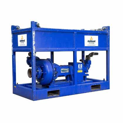
Zone 1 Hydraulic Driven Centrifugal
Pump Specifications
Hydraulic drive / supply
Hydraulic oil type
Max hydraulic flow
Max hydraulic pressure
Max speed
Hydraulic bulkhead connections
Pump
Pump duty
Max pressure
Max flow
Discharge connection
Suction connection
Seal type
Dimensions
Bent-Axis Type Piston Motor
Mineral oil based ( not suitable for water / Glycol based)
225 lpm
230 bar
2,200 rpm
Supply (1") ISO Male A QRC
Return (1 1/2") ISO Male A QRC
Case Drain (3/4") ISO Male A QRC
Mud Hog 4x3x13 Centrifugal Pump
9.3 bar @ 2200 rpm
3000 lpm
4" Fig 206
4" Fig 206
Mechanical seal, heavy duty tungsten carbide c/w viton bellows & labyrinth seal back up
1,700mm 800mm 1,240mm
Length Height Width Weight Gross weight 1,500kg
Applications
Pumping water/mud/brine/ chemicals & crude oil
Features
Engine - Zone 2 Volvo TAMD 27A
Pump - HSP FiFi Single Stage
200-500
Air start
Externally mounted control panel
Shut down system - air operated
DNV certified container package (12x8) & lifting arrangement 2.7-1 ATEX compliant
In the box
Documentation packagemanuals & certification
Comprehensive critical spare parts package
Zone 2 Diesel Driven Centrifugal Pump Set (12 x 8)
Pumping water/mud/brine/chemicals & crude oil
Ashtead Technology has a rental fleet of quality electric, hydraulic and diesel driven centrifugal pumps, covering various applications from 100 hp – 1000 hp. Whether it is a petrochemical Hazardous Area or Safe Area application, or a marine or civil engineering project, Ashtead Technology has a range of pumping equipment to choose from and can tailor solutions for your project requirements. With DNV 2.7-1, ATEX and CE Marking certifications, safety and reliability is guaranteed.
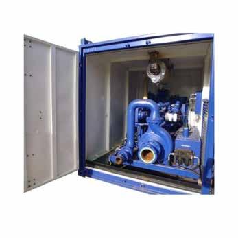
Zone 2 Diesel Driven Centrifugal
Pump Set (12 x 8)
Specifications
Engine type
Fuel type
Maximum RPM
Starting sytem
Clutch type
kW
Volvo TAMD 74A
Diesel 2000
Air motor
Direct drive
Fuel tank capacity 185 kW
Fuel consumption
Controls
Shut down systems
Pump
600 litres
60 litres per hour
Externally mounted control panel c/w all controls and gauges
Air operated - stop, emergency stop, overspeed, high water temp, low oil pressure
type HSP FiFi Single Stage Type 200-500
10 m³/min at 12 bar at
Inlet connection Outlet connection 8" 150 6" 150 or 4" fig 206 Dimensions 2,800mm 3,550mm 2,438mm Height Length Width Weight Max gross certified weight Estimated shipping weight 14,100 kg DNV 2.7-1 8,000 kg (to
confirmed)
Duty
1800 rpm
be
Applications
Pumping water/mud/brine/ chemicals & crude oil
Features
Engine - Zone 2 2012 Iveco 7675 Si
Pump - SPD Mud Hog 4 x 3 x 13
Air start
Externally mounted control panel
DNV certified container package (10 x 8) & lifting arrangment 2.7-1
ATEX compliant
CE marked
In the box
Documentation packagemanuals & certification
Comprehensive critical spare parts package
Zone 2 diesel driven centrifugal pump set (10 x 8 container)
Pumping water/mud/brine/chemicals & crude oil
Ashtead Technology has a rental fleet of quality electric, hydraulic and diesel driven centrifugal pumps, covering various applications from 100 hp – 1000 hp. Whether it is a petrochemical Hazardous Area or Safe Area application, or a marine or civil engineering project, Ashtead Technology has a range of pumping equipment to choose from and can tailor solutions for your project requirements. With DNV 2.7-1, ATEX and CE Marking certifications, safety and reliability is guaranteed.
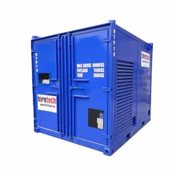
Zone 2 diesel driven centrifugal pump set (10 x 8 container)
Specifications
Engine type
Fuel type
Maximum RPM
Starting system
Clutch type
kW
Controls
Shut down systems
Pump type
Pump duty
2012 Iveco 7675 Si
Diesel (244 litres)
2,100
Air motor (125 cfm at 8 bar)
Over centre clutch
119kW at 2,100 rpm
Externally mounted control panel c/w all controls and gauges
Air operated - stop, emergency stop, overspeed, high water temp, low oil pressure
SPD Mud Hog 4 x 3 x 13
9 bar at 2200 rpm
Maximum pressure Maximum flow 3,600
Inlet connection Outlet connection 4" 206 4" 206 Dimensions Length Width Height 2,990mm 2,442mm 2,576mm Weight Tare weight Payload Gross weight 2,400kg 7,600kg 10,000kg
lpm
Applications
Petrochemical / hazardous & safe area / marine / civil
Features
Zone 2 Detroit 4-71 Diesel
Engine
Air start
Sulzer multi stage centrifugal pump
Externally mounted control panel
DNV certified frame & lifting arrangement 2.7-1
In the box
Documentation packagemanuals & certification
Comprehensive critical spare parts package
Zone 2 Multi STG Centrifugal Pump
Petrochemical / hazardous & safe area / marine / civil
Ashtead Technology has a rental fleet of quality electric, hydraulic and diesel driven centrifugal pumps, covering various applications from 100 hp – 1000 hp. Whether it is a petrochemical Hazardous Area or Safe Area application, or a marine or civil engineering project, Ashtead Technology has a range of pumping equipment to choose from and can tailor solutions for your project requirements. With DNV 2.7-1, ATEX and CE Marking certifications, safety and reliability is guaranteed.
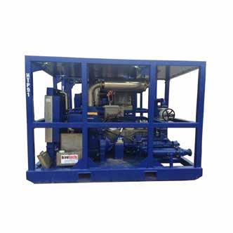
Zone 2 Multi STG Centrifugal Pump
Specifications
Engine type
Fuel type
Tank capacity
Maximum RPM
Starting system
Zone ll Detroit 4 - 71
Diesel 315 litres 2100
Air motor (125cfm at 8 bar)
kW Controls 140 kW at 2100 rpm
Shut down system
Pump
Pump duty
Fluid temperature
Externally mounted control panel c/w all controls and gauges
Air operated - stop, emergency stop, overspeed, high water temp, low engine oil pressure
Sulzer multi stage centrifugal (mechanical seals)
2,550
0⁰C to +50⁰C
6"
4"
Suction connection Dimensions Length 3,500mm Width 2,400mm 4" fig 206 female Gross weight 2,000mm Weight 6,500kg Height
lpm max flow
Discharge connection
150# RF Flange c/w
fig 206 female
Applications
HP jetting (600HP)
Features
Engine - Safe Area Volvo
TAD 1642 VE
Pump - Hammelmann
HDP382
Battery start
Externally mounted control panel
DNV certified container package & lifiting arrangement 2.7-1
CE Marked
In the box
Documentation packagemanuals & certification
Comprehensive critical spare parts package
Safe Area Diesel Driven Hammelmann Jetting Unit (600HP) Duty
204 LPM at 1000 bar
High pressure jetting
Ashtead Technology offers a range of diesel driven Safe Area and ATEX Zone 2 certified high pressure jetting pumps suitable for flows and pressures ranging from 50 lpm – 204 lpm and pressures up to 1000 bar.
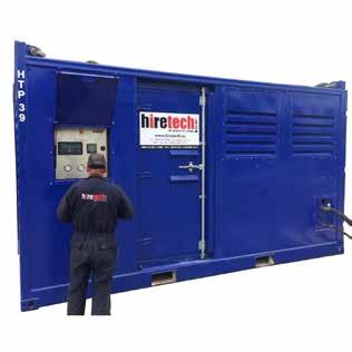
Safe Area Diesel Driven Hammelmann
Jetting Unit (600HP) Duty 204 LPM at 1000 bar
Specifications
Engine specification
Fuel type
Maximum RPM
Starting system
Clutch type
kW
Fuel tank capacity
Fuel consumption
Controls
Pump type
Pump duty
Water supply tank
Charge pump / filteration
Standard connections
Volvo TAD 1642 VE
Diesel 1,800 rpm
Battery start
Twin plate over centre clutch
485 kW at 1800 rpm
887 litres double skinned tank
85 litres per hour
Externally mounted control panel c/w all controls and gauges and emergency stops, Chalwyn v/v and cerfified spark arrestor, 110v s/d
Hammelmann HDP382
204 lpm at 1000bar at 1800rpm
760 litres with low level shut down trip
Suction charge pump via 10 micron filter
3/4" bspm outlet, 2" npt female inlet
Dimensions Height Length Width 2,830mm 4,877mm 2,438mm Maximum gross certified weight Shipping weight 10,600kg
15,500kg
Applications
Pressure testing / well servicing / chemical
pumping
Features
Split skid (engine & pump)
Engine - Zone 2 Diesel driven Detroit S60
Triplex pump - Axon
HD500
Transmission - Allison CLT
6061
Air start
Externally mounted control panel
DNV certified container package & lifting arrangement 2.7-1
ATEX compliant
CE marked
In the box
Documentation packagemanuals & certification
Comprehensive critical spare parts package
Asset
HTP93 A&B
Zone 2 Diesel Driven Pump Unit (single or twin lift)
Pressure testing / well servicing / chemical pumping
Ashtead Technology has a range of air, hydraulic, electrical and diesel driven positive displacement pumps, covering various applications up to 1000 hp.
Our technologies are safe, simple, robust and compliant. Typical models available for rental include the HT400, HD500, Hammelmann, SPM, Hughes, Aqua and Kamat. Skilled operators are also available and training can be given to clients’ personnel to maximise efficiency and ensure safety.
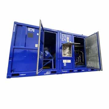
Zone 2 Diesel Driven Pump Unit
(single or twin lift)
Specifications
Engine type
Fuel type
Maximum RPM
Starting system
Rated power
Controls
Shut down system
Transmission
Gear ratios
Gear selection
Triplex pump
Gear
Zone ll Detroit S60
Diesel (800l tank - 9 hrs)
2100rpm
Air motor (125 cfm at 8 bar)
447 kW (450 hhp) at 2100 rpm
Externally mounted control panel c/s all controls and gauges
Stop, emergency stop, overspeed, high water temp, low engine oil pressure, high pump discharge pressure, 110v s/d & 3GP flame trap elimination
Allison CLT 6061 fitted with lock up
4.1, 2.68, 2.01, 1.35, 1.00:1
Roxroth pneumatic 5 speed controller
Axon HD500 fitted with 4" plungers
8.0 to 1
psi (1034)
bbls/min (1,232 lpm)
3" Fig 1502 female (thread)
4" Fig 206 female (thread)
ratio Max pressure Max rate 15,000
7.75
Dimensions Length 3912mm Width 2550mm
Engine Pump Gross weight 3124mm 2812mm 2550mm 3124mm Weight 11,410kg 9,960kg 7,090kg 6,900kg Height Actual weight Discharge connections
connections
Suction
Combined 6800mm 2550mm 3124mm 18,500kg 16,900kg
Applications
Pressure testing / well
servicing /chemical pumping
Features
Split skid (engine & pump)
Engine - Zone 2 Diesel Driven
Detroit
Pump - SPMTWS225
Transmission - Allison DP89625 speed
Air start
Externally mounted control panel
DNV certified container package & lifting arrangement
2.7-1
ATEX compliant
CE marked
In the box
Documentation packagemanuals & certification
Comprehensive critical spare parts package
Asset
HTP67/68/69
Zone 2 Horsepower Diesel Driven Fluid Pump
Pressure testing/ well servicing / chemical pumping
Ashtead Technology has a range of air, hydraulic, electrical and diesel driven positive displacement pumps, covering various applications up to 1000 hp.
Our technologies are safe, simple, robust, and compliant. Typical models available for rental include the HT400, HD500, Hammelmann, SPM, Hughes, Aqua and Kamat. Skilled operators are also available, and training can be given to clients’ personnel to maximise efficiency and ensure safety.
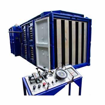
Zone 2 Horsepower Diesel Driven
Fluid Pump
Specifications
Engine type
Fuel type
Fuel consumption
Maximum RPM
Starting system
Power rating
Controls
Shut down system
Transmission
Gear ratios
Gear selection
Zone ll Detroit 16V92TA
Diesel (1500 litre tank - 10hrs)
2.5lpm under full load
2100rpm
Air motor (400cfm at 8 bar)
1070bhp @ 2100rpm (787kW @ 2100rpm)
Engraved stainless-steel pneumatic control panel c/w all controls and monitoring gauges.
Stop, emergency stop, overspeed, high water temp, low engine oil pressure, high discharge pressure
Allison DP8962 5 Speed c/w Neutral Brake
4.24, 2.32, 1.69, 1.31, 1.00:1
Pneumatic selector Triplex
5" Plunger size Max pressire Max rate 11,459psi 16.05 bbls/min (2,552 lpm) Dimensions Length 5480mm Width 2610mm SPM TWS225Engine container Pump container Tare & gross 2850mm 3560mm 2420mm 2730mm Weight 19,500kg 16,500kg 11,300kg 11,300kg Height Actual lift weight
pump
Applications
Nitrogen pumping
Features
Engine - Zone 2 Detroit
12V-71N
Cryogenic pump - GUPD
Triplex
Air start
Externally mounted control panel
DNV certified container package & lifting arrangement
2.7-1
ATEX compliant
CE marked
In the box
Documentation packagemanuals & certification
Comprehensive critical spare parts package
Assets
HTN01
Zone 2 Diesel Driven 180K Nitrogen Converter
Nitrogen pumping
Ashtead Technology has introduced two Nitrogen pumps to its rental fleet. Both units are Zone 2 specification, one has an 180K pump, and one has a twin 90K set up. The units are both silenced and fitted with DNV 2.7-1 lifting frames.
Zone 2 Diesel Driven 180K
Nitrogen Converter Specifications
Engine type
Fuel type
Maximum RPM
Starting system
Rated power
Controls
Shut down systems
Cryogenic pump
Max pressure
Max rate
Discharge connections
Suction connections
Zone ll Detroit 12V-71N
Diesel (600 litre tank - 6hrs) approx 2100 rpm
Air motor (125 cfm at 8 bar)
460bhp at 2100 rpm
Externally mounted control panel c/w all controls and gauges
Air operated - stop, emergency stop, overspeed, high exh temp, high water temp, low engine oil pressure, low pump oil pressure
GUPD Triplex pump 1,5/8" cold ends
10,000psi
180,000 SCFH of LN2 @ 20°C 2" 1502
NIT 150 male
Dimensions 5890mm Length Width Height 2738mm 2488mm Weight Max gross 16,500kg Actual weight 12,650kg
Applications
Submersible pumping
Features
Hydraulically driven single stage pump
Parker F12-80 piston monitor
Duty (typical) - 500m3/hr @ 4bar (40m lift)
In the box
Documentation packagemanuals & certification
Hydraulic driven submersible lift pump
Portable multi use submersible lift pump
A simple and reliable hydraulically driven submersible lift pump. Used in a variety of general industrial, onshore & offshore applications when a small and portable pump is
Hydraulic driven submersible lift
pump Specifications
Pump
Pump duty (typical)
Impeller Ø
Discharge connection
Suction
Hydraulic motor
Max hydraulic pressure
Max hydraulic flow
Hydraulic oil
Supply connection
Return connection
Drain connection
Dimensions
Single stage volute, 3 bladed fully open impeller
500m³/hr @ 4 bar (40m lift)
250mm (Bronze)
200mm (8" #150 RF Flange)
400 x 100mm suction screen c/w Ø 7mm holes
Parker F12-80 Bent Axis Piston Motor
330 bar
220 litres/minute
Mineral based (HPX32) "Not water based"
1" quick disconnect
1¼” quick disconnect
½” quick disconnect
c/w 8" #150 RF flanged lifting sub Width
460mm
220kg (Approx.)
Weight
Approx weight
(dry c/w lift sub)
Height Length
600mm 1000mm
Applications
Submersible pumping
Features
Hydraulically driven single stage volute pump
19cc Bent Axis Piston Motor
6 bladed fully open bronze impeller
Duty (typical) - 70m3/hr @ 4.9bar (50m lift)
In the box
Documentation packagemanuals & certification
Hydraulic driven submersible lift pump
Portable multi use submersible lift pump
A simple and reliable hydraulically driven submersible lift pump. Used in a variety of general industrial, onshore & offshore applications when a small and portable pump is required for the safe and efficient transfer of a variety of fluids.
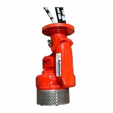
Hydraulic driven submersible lift
pump Specifications
Pump
Pump duty (typical)
Impeller Ø
Discharge connection
Suction
Hydraulic motor
Max hydraulic pressure
Max hydraulic flow
Hydraulic oil
Supply connection
Return connection
Drain connection
Discharge connection
Dimensions
Height Length
Width
Approx weight
Weight (dry c/w lift sub)
Single stage volute, 6 bladed fully open impeller
70m³/hr @ 4.9 bar (50m lift)
220mm (Bronze)
100mm (4" #150 RF Flange)
230 x 100mm suction screen c/w Ø 7mm holes
19cc Bent Axis Piston Motor
200 bar
70 lpm
Mineral based (HPX32) "Not water based"
¾" quick disconnect
¾” quick disconnect
½” quick disconnect
c/w 4" #150 RF flange
650mm
350mm
350mm
50kg (Approx.)
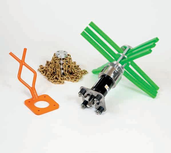
Cleaning tools
Manipulators
Hydraulic power pumps & reelers
Sampling tools
Intervention skids 06
Cleaning tools
06
07
08
09
10
Section 6
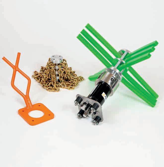
Applications
Wellhead cleaning
Features
Stainless steel handle
Simple scrubbing pad replacement
Light weight aluminium and plastic construction
Guide nose for ease of use
In the box
Wellhead Cleaning Tool
ROV handle
Spare scotch brite cleaning pads
Operational hoses
Operations and maintenance
manual
Consumables
Spare Scotbrite
Wellhead Cleaning Tool
Ideal for AX or VX gaskets
The motorised wellhead cleaning tool is designed to clean the seal surface of wellheads that use AX or VX gaskets. The ROV powers the tool and holds it in position to remove debris. Flow regulator valves limit the rotation speed while still allowing high torque.
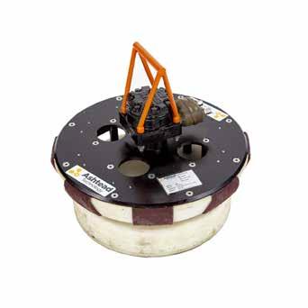
Wellhead Cleaning Tool
Specifications
Input pressure
Input flow
Weight in air
Weight in water
Cleaning depth
Materials
To suit
Hoses
138bar to 207bar / 2000psi to 3000psi
+5.7lpm / 1.5+gpm
24kgs / 52lbs
16kgs / 35lbs
317.5mm / 12.5in
Aluminum, UHMW/HDPE, stainless steel, plastic, abrasive pads
18-3/4” AX/VX wellhead interface
2 x 4 JIC female swivel hose, 4m
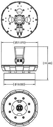
Applications
Marine growth removal
Acid injection cleaning
Features
Superior brush head
Fishtail handle
Weighs less than 10kg / 22lbs
Can be used with acid injection system
In the box
12.5” cleaning brush
Operational hoses
Operations and maintenance manual
12.5” Cleaning Brush
Ideal for marine growth removal
Subsea cleaning and marine growth removal has never been easier. Designed to be simply attached to a manipulator and operated by an ROV system, this tool combines a plastic bristled brush head with an integrated injection system, delivering additional cleaning fluids when and where necessary.
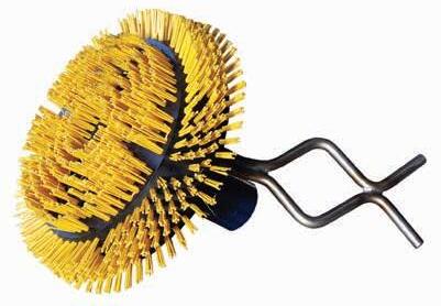
12.5” Cleaning Brush
Specifications
Pressure 140bar / 2000psi
Flow 20lpm / 5.2gpm
Depth rating 3000m / 9842ft
Specifications
Motor EPRM50C
Mounting manipulator handle
Brush size 317.5mm / 12.5in
Weight In air 10kg / 22lbs
Pressure / return 4 JIC hose x 2
Case drain 4 JIC hose 4 JIC hose
Acid injection
Applications
Riser cleaning
Vessel hull cleaning
Mooring chain cleaning
Electrical power cable cleaning
Subsea socket cleaning
Features
Highly effective at removing marine growth from geometrically complex components
Constructed from materials that will not damage subsea components
Speeds up inspection times, saving clients vessel / ROV costs
Uses polymer fingers that spin up to 1000rpm
Brass chain option
In the box
Subsea cleaning tool
Polymer rods
Chain flail
Spares kit
Operations and maintenance
manual
Operational hoses
Ashtead Technology Subsea Cleaning Tools
Ideal for removing marine growth
Ashtead Technology's Subsea Cleaning Tool's are used to quickly and effectively remove difficult marine growth from mooring chains and other subsea components. Ashtead’s Subsea Cleaning Tool's dramatically improves chain cleaning time and saves clients money by reducing boat / ROV time required for inspection preparation.
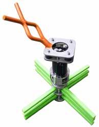

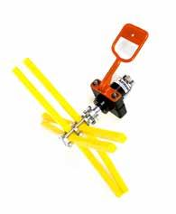
Mini Subsea Cleaning Tool
Subsea Cleaning Tool
Ashtead Technology Subsea
Cleaning Tools
Specifications
Standard:
Flow rate requirement
Pressure
Motor
Depth rating
Assembled weight (standard)
Assembled weight (flail)
Low flow:
Flow rate requirement
Motor
Depth rating
Assembled weight (standard)
Assembled weight (flail)
Consumables
Orange flogger rod
Yellow flogger rod
Green flogger rod
Chain flails
Hydraulic connections
Pressure
Return
Case drain
Subsea Cleaning Tool
30lpm / 7.8gpm to 70lpm / 18.4gpm
recommended 40lpm / 10.6gpm
Mini Subsea Cleaning Tool
7lpm / 1.9gpm to 16lpm / 4.3gpm recommended 10lpm / 2.7gpm
75bar / 1080psi to 180 bar / 2610psi recommended 140bar / 2030psi
Variable speed, reversible (default is clockwise)
3000m / 9842ft
11kg / 24lbs
13.5kg / 30lbs
12lpm / 3.2gpm to 30lpm / 7.9gpm
Variable speed, reversible (default is clockwise)
3000m / 9842ft
11kg / 24lbs
13.5kg / 30lbs
Grade - soft
Grade - medium
Grade - hard
Brass (standard) / stainless steel
8 JIC hose
8 JIC hose
6 JIC hose
Variable speed, reversible (default is clockwise)
3000m / 9842ft
6.3kg / 14lbs
3.8kg / 8lbs
Grade - soft
Grade - medium
Grade - hard
Brass (standard) / stainless steel
4 JIC 4m hoses
4 JIC 4m hoses
-
-
-
-
-
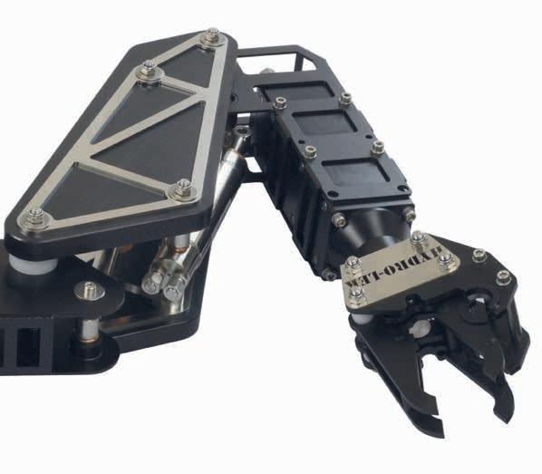
Cleaning tools
Manipulators
Hydraulic power pumps & reelers
Sampling tools
Intervention skids 07
06
07
08
09
10
Section 7 Manipulators
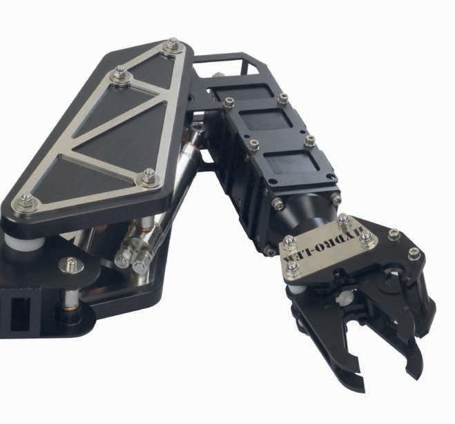
Applications
Subsea grasp & lifting operations
ROV anchoring
Features
Acute precision control
Large operating envelope
High lift-to-weight ratio
Depth rating up to 7,000m / 22,965ft
Titanium construction
In the box
FMC Schilling Robotics Titan 4
Operational hoses
Operations and maintenance manual
FMC Schilling Robotics Titan 4
World’s premier servo-hydraulic remote manipulator
Thousands of FMC Schilling manipulator systems are in use worldwide every day. TITAN manipulators are the highest quality system on the market for the dexterity and strength needed to withstand the industry’s harsh and repetitive needs day after day.
The TITAN 4 is widely regarded as the world’s premier servo-hydraulic remote manipulator system. Since 1987, these systems have been the industry standard for dexterous manipulator systems used in subsea applications, and are extensively used on ultra-heavy work class ROVs.
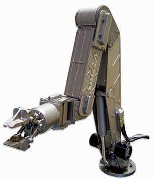
FMC Schilling Robotics Titan 4
Specifications
Reach 1.92m / 6.3ft
Type
Position controlled
Functions 7
Materials
Primarily titanium
Standard depth 4,000m / 13,123ft
Weight in air 100kg / 220.4lbs
Weight in water 78kg / 171.9lbs
Lift at full extension 122kg / 268.9lbs
Maximum lift, nominal 454kg / 1000lbs
Standard gripper opening 99mm / 3.9in
Grip force, nominal 4,092N
Wrist torque, nominal 170Nm
Wrist rotate, continuous 6-35rpm
Input power, controller
Input power, arm
Power, controller
Power, arm
Telemetry
Fluid
Viscosity
Available flow
Max pressure
Max fluid temperature
Fluid cleanliness
90-260VAC
24 VDC
6w start, 3w run
6w start, 45w run
RS-232 or RS-422/485
Mineral, glycol, or synthetic
10-200cSt
5.7-19lpm / 1.5-5gpm
207bar / 3000psi
54ºc / 129ºfe
ISO 4406 14/11
Pressure Return Comp 6 JIC hose 8 JIC hose 4 JIC hose
Features
High-resolution color camera
Integrated titanium housing
Includes two bright LED lights with two illumination levels
No external cables
NTSC or PAL
Standard depth rating of 4,000 msw
Lights and camera managed by the master controller
Schilling Robotics T4 Wrist Camera
High-resolution colour camera
The wrist camera features an integrated titanium camera housing and internal cabling, offering superior protection and eliminating cable snags and abrasion. The wrist-mounted TITAN integrated camera provides operators with an exceptional view of tasks being performed. The high-resolution camera and two bright LED lights are contained in an integrated titanium housing for maximum protection. Since signals and power are routed though the manipulator arm, there is no external cabling that can be snagged or abraded. Both NTSC and PAL cameras are available. The manipulator wrist camera is compatible with any TITAN manipulator arm that features in-arm electronics.
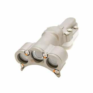
Schilling Robotics Titan Wrist Camera
Specifi cations
Image sensor
Effective pixels NTSC
Horizontal resolution
Min illumination
Video output
Signal-to-noise ratio
Lens
Power consumption
In-arm electronics
Including camera and lights at full intensity
Camera and lights only
Depth rating
Operating temp
1/3 colour super HAD CCD
752 x 582 PAL: 768 x 484 480 TV lines 0.3 lux at F2.0 1.0 Vp-p composite 75 Ohms 3.6mm (39 degrees) 0.75 A at 24 VDC 0.25 A at 24 VDC, at full intensity 4,000 msw -10C to 50C
More than 50db
Applications
Subsea grasp & lifting operations
ROV anchoring
Features
Robust design
Long service life
Large operating envelope
Highest lift-to-weight ratio in its class
Interchangeable jaw configurations
Boom function extends arm length by 305mm / 12in
Standard depth rating of 6,500m / 21,325ft
In the box
FMC Schilling Robotics RigMaster Operational hoses
Operations and maintenance manual
FMC Schilling Robotics RigMaster
Heavy duty 5-function manipulator arm
For nearly every TITAN 4 manipulator in the market, there is a RigMaster supporting the mission. Its titanium construction makes it a durable and reliable in heavy work class missions.
The RigMaster is a five-function, rate-controlled, heavy-lift grabber arm that can be mounted on a wide range of subsea ROVs. It is engineered for the strength needed to withstand the industry’s harsh and repetitive needs day after day. The grabber arm can be used to grasp and lift heavy objects or to anchor the ROV by clamping the gripper around a structural member at the work site.
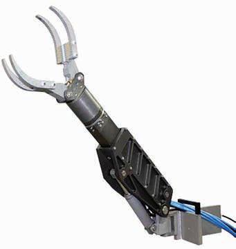
FMC Schilling Robotics RigMaster
Specifications
Reach 1.06-1.37m / 3.47-4.49ft
Type Rate controlled
Functions 5
Materials
Anodized aluminum, stainless steel, titanium
Standard depth 6,500m / 21,325ft
Weight in air 64kg / 141lbs
Weight in water 48kg / 105.8lbs
Lift at full extension 181kg / 399lbs
Maximum lift, nominal 270kg / 595.2lbs
Standard gripper opening 284mm / 11.1in
Grip force, nominal 4,448N
Wrist torque, nominal 205Nm
Wrist rotate, continuous
Base yaw
Shoulder pitch
Boom, extend/retract
Wrist pitch
Wrist rotate
Gripper, standard
Fluid
Viscosity
Available flow
Maximum pressure
Maximum fluid temperature
Fluid cleanliness
Actuator return pressure
Filtration
Open / close CW/CCW
Extend / retract
Left/right
6-35rpm
Linear, 105º
Linear, 105º Linear, 305mm / 12in
Linear, 120º
Gerotor, 360º
Linear, 284mm / 11.1in Mineral, glycol, or synthetic
10-200cSt
5.7-19lpm / 1.5-5gpm
207bar / 3000psi
54ºc / 129ºf
ISO 4406 14/11
24.1bar / 350psi 10 microns
2 x 4 JIC hose 2 x 4 JIC hose 2 x 4 JIC hose 2 x 4 JIChose 2 x 4 JIC hose 4 JIC hose
Up/down Comp
8
Cleaning
06
tools
Manipulators
Intervention
08
07
08 Hydraulic power pumps & reelers 09 Sampling tools 10
skids
Section
Hydraulic power pumps & reelers
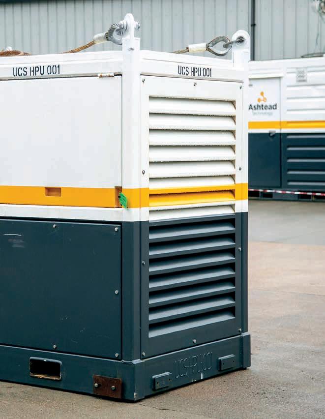
Applications
Deck testing ROV tools
Features
Mounted in stainless steel frame
75litre / 19.8gal tank capacity
440VAC electrical supply
Selectable output range Hydraulic
soft start
Relief valve
Pressure gauges
Oil cooler
In the box
7.5kw hydraulic power unit
Certified lifting slings
Certified stainless steel frame with fork lift pockets
Operations and maintenance manual
7.5kw Hydraulic Power Unit (HPU) ROV deck pack
The 7.5kw Hydraulic Power Unit (HPU), a complete power generation system designed to convert electrical input into a useable hydraulic power source for local supply to hydraulically operated tools and machinery. Primarily designed for the offshore industry to run an ROV system in power mode whilst additionally capable of function testing a complete ROV package with any associated tooling requirements attached, the system can also be used for many other hydraulic power applications both onshore and offshore.
The hydraulic circuit is split in to 2 separate systems. The main system allows output of a single pressure and flow to a maximum of 210bar and 30lpm. The directional control valve system, allows adjustable pressure via a pressure reducing valve providing an additional electable output range from 0-210bar at the same time.
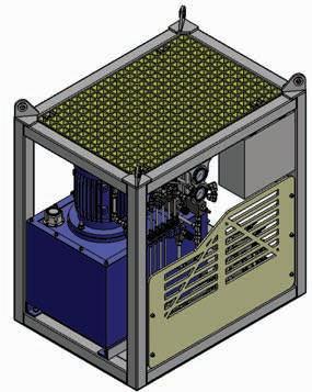
1" Air Powered Umbilical Reel c/w
Open Core Centre
Specifications
Power drive specification
Air motor type
Peak air consumption
Peak power
Braking
Emergency brake
Drum
Speed
Line pull
Inner drum diameter
Flange diameter
Length of drum
Overall frame dimensions
Length
Width
Height
Weight
Tare width
Payload
Gross weight
Rotary piston
210 cfm at bar
4 kW at 1800 rpm
Brake tested to 1500kg
Fitted
10 rpm
1500 kg max
1000 mm
1700 mm
1000 mm
2020 mm
1500 mm
2100 mm
2500 kg
2000 kg
4500 kg
Applications
Storage - deployment & recovery of hose & umbilical
Features
Air driven
Local control
Brake tested to 2470kg
Emergency brake
DNV certified frame & lifting arrangement 2.7-1
CE marked
ATEX compliant
In the box
Documentation package& certification
Comprehensive critical spa package
2" Air Powered Umbilical Reel
Storage - deployment & recovery of hose & umbilical
Ashtead Technology has set the standard for powered umbilical reels, with our models becoming the generic terms of reference across the industry. Models include the 1”, 2”, 4” Type 5 and Type 6 reels, which can deploy hoses and umbilicals from ¼” up to 2,500m of 110mm diameter. Our Type 5 reel can also be used to deploy our 6” hard wall hose. Our reels are designed, built, and certified to DNV standards and are
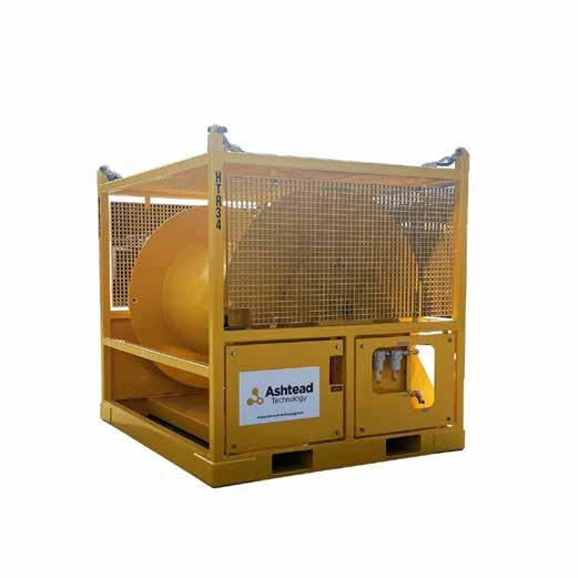
2" Air Powered Umbilical Reel
Specifications
Power drive specification
Air motor type
Peak air consumption
Peak power
Braking
Emergency brake
Drum
Speed
Line pull
Inner drum diameter
Flangediameter
Length of drum
Overall frame dimensions
Length
Width
Height
Weight
Tare width
Gross weight
Rotary piston
350 cfm at 8 bar
7.5 kW peak
Brake tested to 2470kg
Fitted
6 rpm
3000 kg max
1150 mm
1837 mm
1980mm
2255 mm
2555 mm
2415 mm
3500 kg
6500 kg
Applications
Storage - deployment & recovery of hose & umbilical
Features
Air driven
Local control
Brake tested to 3700kg
Manually operated drum locking pin
DNV certified frame & lifting arrangement 2.7-1
CE marked
ATEX complaint
In the box
Documentation packagemanuals & certification
Comprehensive critical spare parts
4" Air Powered Umbilical Reel
Storage - deployment & recovery of hose & umbilical
Ashtead Technology has set the standard for powered umbilical reels, with our models becoming the generic terms of reference across the industry. Models include the 1”, 2”, 4” Type 5 and Type 6 reels, which can deploy hoses and umbilicals from ¼” up to 2,500m of 110mm diameter. Our Type 5 reel can also be used to deploy our 6” hard wall hose. Our reels are designed, built, and certified to DNV standards and a
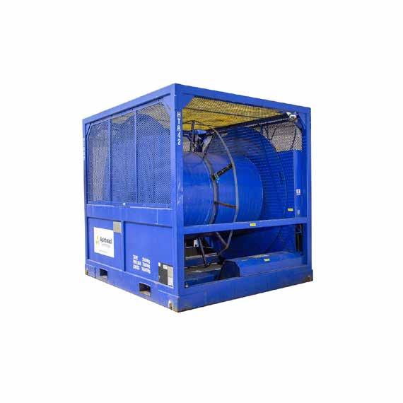
4" Air Powered Umbilical Reel
Specifications
Power drive specification
Air consumption
Maximum power
Braking
Emergency brake
Drum
Drum speed
Maximum line pull
Maximum designed brake load
Core diameter
Flange diameter
Overall frame dimensions
Length
Payload
Gross
400 cfm at 8 bar 14 kW
Factory fitted hand brake rating to 3700kg
Manually operated lock pin
3.2 rpm 3700 kg 3700 kg 1600 mm
Width Height Weight
Tare weight
weight
2745
3300
2870
3050
7000
7600
of drum 2285
mm
mm
mm
mm
kg
kg Length
mm
14600
kg
Applications
Storage - deployment & recovery of hose & umbilical
Features
Air driven
Dual brakes
Manually operated drum locking pin
Remote control panel with e-stop
Spooling gear - manually controlled/air operated
DNV certified frame & lifting arrangement 2.7-1
CE marked
ATEX compliant
In the box
Documentation packagemanuals & certification
Comprehensive critical spare parts package
Type 5 Air Powered Umbilical Reel c/w Spooling Gear & Remote Control
Storage - deployment & recovery of hose & umbilical
Ashtead Technology has set the standard for powered umbilical reels, with our models becoming the generic terms of reference across the industry. Models include the 1”, 2”, 4” Type 5 and Type 6 reels, which can deploy hoses and umbilicals from ¼” up to 2,500m of 110mm diameter. Our Type 5 reel can also be used to deploy our 6” hard wall hose. Our reels are designed, built, and certified to DNV standards and are designed to deploy, brake, and recover their maximum payloads. Live fluid and electrical slip ring centres can be fitted where required.
We can also offer powered umbilical reels certified to NORSOK Z-015 Rev 4. Ashtead
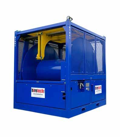
Type 5 Air Powered Umbilical Reel c/w Spooling Gear & Remote Control
Specifications
Power drive specification
Air consumption
Braking (dual brakes)
Emergency brake
Controls
Drum
Drum speed
Maximum line pull
Maximum designed brake load
Core diameter
Flange diameter
Spooling gear
Type
Spooling gear carriage max speed
Over travel protection
Overall frame dimensions
400 cfm at 8 bar
Brakes tested to 5000kg
Manually operated lock pin
Remote panel with emergency stop, drum speed & direction control and spool control
3.2 rpm
5000 kg (Ø 1850 mm core)
5000 kg
1850 mm
3351 mm
Manually controlled/air operated
1.5cm per second
Limit switches fitted to prevent over travel
3886 mm
3320
5 leg lifting sling set
Only lift empty
Length of drum 2572
mm Length (across drum diameter) Height Payload (across drum diameter) Weight Tare weight
Payload Gross weight
8200 kg 15000 kg
kg
mm
mm 3920
Lifting
Forklift
23200
Applications
Storage - deployment & recovery of hose & umbilical
Features
Air driven
Brake tested to 3700kg
Manually operated drum locking pin
Remote control panel with estop
Spooling gear - manually controlled/air operated
DNV certified frame & lifting arrangement 2.7-1
CE marked
ATEX compliant
In the box
Documentation packagemanuals & certification
Comprehensive critical spare parts package
Type 6 Air Powered Umbilical Reel c/w spooling gear
Storage - deployment & recovery of hose & umbilical
Ashtead Technology has set the standard for powered umbilical reels, with our models becoming the generic terms of reference across the industry. Models include the 1”, 2”, 4” Type 5 and Type 6 reels, which can deploy hoses and umbilicals from ¼” up to 2,500m of 110mm diameter. Our Type 5 reel can also be used to deploy our 6” hard wall hose. Our reels are designed, built, and certified to DNV standards and are designed to deploy, brake, and recover their maximum payloads. Live fluid and electrical slip ring centres can be fitted where required.
We can also offer powered umbilical reels certified to NORSOK Z-015 Rev 4. Ashtead Technology has an extensive stock of hoses and hydraulic umbilicals ranging from ¼” to 6” id available for rental with our reels..
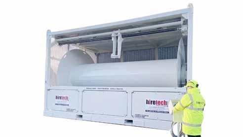
Type 6 Air Powered Umbilical Reel c/ w spooling gear
Specifications
Power drive specification
Peak air consumption
Maximum power
Braking
Emergency brake
Controls
Drum
Drum speed
Maximum line pull
Maximum designed brake load
Core diameter
Flange diameter
Spooling gear
Type
Spooling gear carriage max speed
Over travel protection
Overall frame dimensions
Payload (across drum diameter)
Height
Payload
Gross
Lifting
Forklift
400 cfm at 8 bar 14 kW
Brake rated to 3,700kg
Manually operated lock pin
Remote panel with emergency stop, drum speed & direction control and spool control
3rpm
3,700kg 3,700kg
Manually controlled/air operated 1.5cm per second
Limit switches fitted to prevent over travel
4 leg lifting sling set
Only lift empty
1,600mm 3,350mm
6,725mm 4,015mm Length of drum 5,855mm 4,230mm
Length (across drum diameter)
weight
Weight Tare
weight
15,000kg 30,000kg 45,000kg
Applications
Deck testing ROV tools
Features
Mounted in stainless steel frame
75litre / 19.8gal tank capacity
440VAC electrical supply
Selectable output range
Hydraulic soft start
Relief valve
Pressure gauges
Oil cooler
In the box
7.5kw hydraulic power unit
Certified lifting slings
Certified stainless steel frame with fork lift pockets
Operations and maintenance manual
7.5kw Hydraulic Power Unit (HPU) ROV deck pack
The 7.5kw Hydraulic Power Unit (HPU), a complete power generation system designed to convert electrical input into a useable hydraulic power source for local supply to hydraulically operated tools and machinery. Primarily designed for the offshore industry to run an ROV system in power mode whilst additionally capable of function testing a complete ROV package with any associated tooling requirements attached, the system can also be used for many other hydraulic power applications both onshore and offshore.
The hydraulic circuit is split in to 2 separate systems. The main system allows output of a single pressure and flow to a maximum of 210bar and 30lpm. The directional control valve system, allows adjustable pressure via a pressure reducing valve providing an additional electable output range from 0-210bar at the same time.
7.5kw Hydraulic Power Unit (HPU)
Specifications
Output pressure 210bar / 3000psi
Output flow 30lpm / 7.9gpm
Pressure filter 6micron (non-bypass)
Return filter 25micron
Electrical power 7.5kw
Electrical supply 440VAC
Reservoir capacity 75 litres / 19.8gal
Wire configuration Wired for star/delta with breakers & emergency stop c/w 10m / 32.8ft flying lead
/
Weight 430kg
Dimensions 1000 x 730 x 1100mm / 39.3 x 28.7 x 43.3in
948lbs
Applications
Deck testing ROV tools
Features
Mounted in stainless steel frame
200 litre / 52.8gal tank capacity
440VAC electrical supply
Selectable output range
CJC water separation filter
Hydraulic soft start
Relief valve
Pressure gauges
Oil cooler
In the box
22kw Hydraulic Power Unit
Certified lifting slings
Certified stainless steel frame with fork lift pockets
Operations and maintenance manual
30m of 3 phase umbilical
22kw Hydraulic Power Unit (HPU) ROV deck pack
The 22kw Hydraulic Power Unit (HPU), a complete power generation system designed to convert electrical input into a useable hydraulic power source for local supply to hydraulically operated tools and machinery. Primarily designed for the offshore industry to run an ROV system in power mode whilst additionally capable of function testing a complete ROV package with any associated tooling requirements attached, the system can also be used for many other hydraulic power applications both onshore and offshore.
The hydraulic circuit is split in to 2 separate systems. The main system allows output of a single pressure and flow to a maximum of 250bar and 55lpm. The directional control valve system, allows adjustable pressure via a pressure reducing valve providing an additional electable output range from 0-250bar at the same time.
The on-board CJC unit is designed to provide fine filtration and water separation capable of cleaning hydraulic oils to 3 microns absolute, ensuring trouble free operation of ROV hydraulic systems where water ingress is a constant problem.
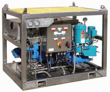
22kw Hydraulic Power Unit (HPU)
Specifications
Output pressure 250bar / 3600psi
Output flow 55lpm / 14.5gpm
Pressure filter 6micron (non-bypass)
Return filter 25micron
Electrical power 22kw
Electrical supply 440VAC
Reservoir capacity 200 litres / 52.8gal
Wire configuration Wired for star/delta with breakers & emergency stop c/w 10m / 32.8ft flying lead
Weight 1t Dimensions 1350 x 1000 x 1129mm / 53.1 x 39.3 x 44.4in
Applications
To power a variety of hydraulic tooling & associated equipment
Features
Safe area JCB 444
Dieselmax engine
Open loop - pressure compensated pump
Battery start
Robust safety/shutdown system
DNV certified frame & lifting arrangement 2.7-1
CE marked
In the box
Documentation packagemanuals & certification
Comprehensive critical spare parts package
Safe Area Diesel Driven 93kW Hydraulic Power Pack
To power a variety of hydraulic tooling & associated equipment
Ashtead Technology’s range of Hydraulic Power Units (HPUs) are suitable for both onshore and offshore applications. All units are certified to DNV 2.7-1 with built in flow meters, filtration, and oil cooling options. The Hydraulic Power Pack units can be flushed to NAS 6 or similar prior to rental. We typically use HPX32 grade hydraulic oils, however other oils can also be considered. Our skilled personnel have over 30 years’ experience building Hydraulic Power Packs and use that knowledge to ensure our
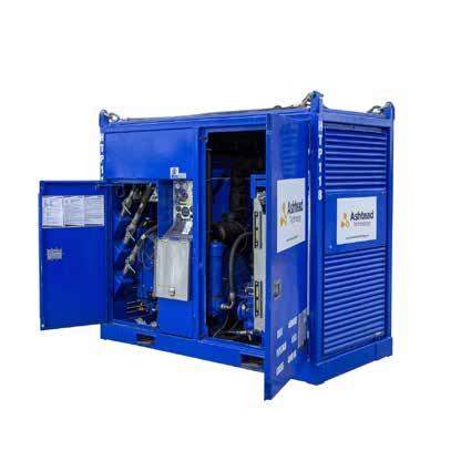
Safe Area Diesel Driven 93kW
Hydraulic Power Pack Specifications
Engine type
Rated speed and kW
Starting system
Fuel consumption
Fuel tank capacity
Safety / shut down systems
Hydraulic pump
Max pressure
Max flow
Max hydraulic kW
Oil cooling
Relief valve
Hydraulic oil tank capacity
Connections
Hydraulic oil type
Safe Area JCB 444 TCA Dieselmax
93 kW at 2200 rpm
Battery start
25 litres per hour at rated speed & power
208 litres
Stop, emergency stop, overspeed 'Chalwyn Valve', high coolant temp, low oil pressure, high hydraulic oil temp, low hydraulic oil level 110 volt remote shut down & exhaust spark arrester fitted.
Open loop pressure compensated
320 bar 'continuous' / 350 bar 'peak' 0 - 280 lpm (2000 rpm)
75 kW
Air to oil hydraulically driven
Adjustable 0 - 380 bar
440 litres
Supply 1.25" nptf, return 1.5" nptf, case 1" nptf Case Drain 1" nptf
Mineral oil based (not water/glycol based)
Dimensions Height Length Width 2280 mm 2500 mm 1230 mm Weight Gross weight 4000 kg
Applications
Safe area - portable compressed air supplyback deck/onshore/
offshore
Features
FAD - 400CFM @ 10bar
Engine - John Deere
Air end - Ingresoll Rand
Battery start
DNV certified lifting frame & lifting arrangement
2.7-1
In the box
Documentation packagemanuals & certification
Comprehensive critical spare parts package
Safe Area Diesel Driven 400 CFM
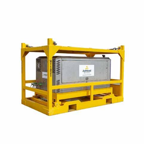
Safe Area Diesel Driven 400 CFM 10
Bar Air Compressor Specifications
Engine type
Rated power
Speed at full load
Speed at idle (no load)
Starting system
Fuel tank capacity
Fuel consumption
Safety features
Air end
Free air delivery
Normal operating discharge pressure
Maximum allowable pressure
Safety valve setting Discharge
John Deere 4045HF285 (4.5l)
93 kW at 2200 rpm
2200 rpm
1500 rpm
Battery start
219 liters (8 hours running full load)
24 - 26 litre/hour (load dependant)
Emergency stop, spark arrester, Chalwyn overspeed protection
Ingersoll rand
fittings
375 cfm 10.3 bar 12.1 bar 3 x crows foot, 1 x 1¼” npt (F) 13.8 bar Dimensions 3200 mm Length Width Height 1800 mm 2070 mm Weight Gross weight 4000 kg
Applications
To power a variety of hydraulic tooling & associated equipment
Features
Engine - Safe Area Caterpillar 3406 engine
Pump - Rexroth A11VO
Axial Piston Variable (open loop)
Air start
Safety / shutdown system
DNV certified container package & lifting arrangement 2.7-1
CE marked
In the box
Documentation packagemanuals & certification
Comprehensive critical spare parts package
Safe Area Diesel Driven 460 LPM Hydraulic Power Pack
To power a variety of hydraulic tooling & associated equipment
Ashtead Technology’s range of Hydraulic Power Units (HPUs) are suitable for both onshore and offshore applications. All units are certified to DNV 2.7-1 with built in flow meters, filtration, and oil cooling options. The Hydraulic Power Pack units can be flushed to NAS 6 or similar prior to rental. We typically use HPX32 grade hydraulic oils, however other oils can also be considered. Our skilled personnel have over 30 years’ experience building Hydraulic Power Packs and use that knowledge to ensure our
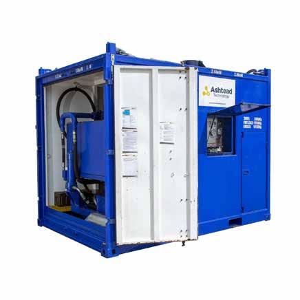
Safe Area Diesel Driven 460 LPM
Hydraulic Power Pack Specifications
Engine type
Rated speed
Starting system
Fuel consumption
Fuel tank capacity
Safety / shut down systems
Hydraulic pump
Max pressure
Max flow
Max hydraulic kW
Oil cooling
Relief valve
Hydraulic oil tank capacity
Connections
Hydraulic oil type
Caterpillar 3406
1,800 rpm
Air motor (8 bar at 125cfm)
375 kW
100 litres per hour
500 litres
Air operated - stop, emergency stop, overspeed, high water temp, low oil pressure, high hyd oil temp, low hyd oil level (110 v s/d on request)
Rexroth A11VO Axial Piston Variable Pump (open loop pressure compensated)
Adjustable 0 - 350 bar
Adjustable 0 - 468
TBA
Ext water supply required for heat exchanger
Adjustable 930 litres
1.5" bsp supply/2" bsp return or as agreed
Mineral oil based (not water/glycol based)
Dimensions Height Length Width 2,830 mm 3,550 mm 2,438 mm Weight Actual weight 7,700kg Output
Gross weight 14,100kg
Applications
To power a variety of hydraulic tooling & associated equipment
Features
Zone 1 - ATEX certified
Multi voltage electric motor 50/60 hz
Starter - Star Delta
Open loop - pressure compensated pump
DNV certified frame & lifting arrangement 2.7-1
CE marked
In the box
Documentation package - manuals & certification
Comprehensive critical spare parts package
Zone 1 Electric Driven 37/43 KW Hydraulic Power Pack
To power a variety of hydraulic tooling & associated equipment
Ashtead Technology’s range of Hydraulic Power Units (HPUs) are suitable for both onshore and offshore applications. All units are certified to DNV 2.7-1 with built in flow meters, filtration, and oil cooling options. The Hydraulic Power Pack units can be flushed to NAS 6 or similar prior to rental. We typically use HPX32 grade hydraulic oils, however other oils can also be considered. Our skilled personnel have over 30 years’ experience building Hydraulic Power Packs and use that knowledge to ensure our technologies are safe, simple, robust, and compliant. Typical components include JCB, Volvo, Caterpillar, Kawasaki, Parker and MPI Filtri.
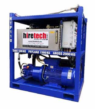
Zone 1 Electric Driven 37/43 KW
Hydraulic Power Pack
Specifications
Specification
Electric motor
Controls / starter
Instruments / system shutdowns
Hydraulic pump
Typical flow rates and pressures
Hydraulic tank
Oil cooler
Filteration
Supply fitting (Bulkhead)
Return fitting (Bulkhead)
Case drain (Bulkhead)
Hydraulic oil type
ll 2G EEx d llB T4 (Zone 1) IP56
Multi voltage 380 - 440 v (3ph, 50/60 hz)
Star Delta c/w overload protection, stop, start, emergency stop, load, unload & hydraulic pressure control
Digital flow meter, supply & return hydraulic oil pressure guages, oil temp gauge, low oil level & high oil temp shutdowns & phase protection.
Axial piston, pressure compensated
140 lpm at 145 bar
98 lpm at 207 bar
50 lpm at 320 bar
Stainless steel 300 litre capacity
Integral air to oil hydraulically driven blast cooler
Tank mount suction filter, in line pressure Filter & tank top return filter
1" NPT female
1,¼" NPT female
¾" NPT female
Mineral oil (not water/glycol based)
1880 mm
Dimensions
Height Length Width 2000 kg 1650 mm Weight Gross weight 1110 mm
Applications
To power a variety of hydraulic tooling & associated equipment
Features
Zone 2 - ATEX certified
JCB 444 Dieselmax engine
Air start
Open loop - pressure compensated pump
Robust safety / shutdown system
DNV certified container package & lifting arrangement 2.7-1
CE marked
In the box
Documentation packagemanuals & certification
Comprehensive critical spare parts package
Zone 2 Diesel Driven Hydraulic Power Pack
To power a variety of hydraulic tooling & associated equipment
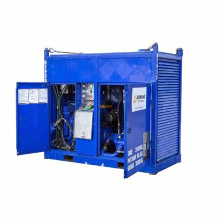
Zone 2 Diesel Driven Hydraulic Power Pack
Specifications
Engine type
Rated speed and kW
Starting system
Fuel consumption
Fuel tank capacity
Shut down systems
Hydraulic pump
Max pressure
Max flow
Max hydraulic kW
Oil cooling
Relief valve
Hydraulic oil tank capacity
Connections
Hydraulic oil type
Zone 2 JCB 444 Dieselmax
56.7 kW at 2200 rpm
Air motor 400 cfm @ 5.5 bar min.
20 litres per hour
208 litres
Air operated - stop, emergency stop, overspeed, high water temp, low oil pressure, high exhaust temp, high hydraulic oil temp, low hydraulic oil, 110 v s/d
Open loop pressure compensated
Adjustable 0 - 320 bar
Adjustable 0 - 280 lpm (2000 rpm)
56.7 kW
Air to oil hydraulically driven
Adjustable
440 litres
Supply 1.25" nptf, return nptf, case 1" nptf
Mineral oil based (not water/glycol based)
Dimensions Height Length Width 2280 mm 2500 mm 1230 mm Weight Gross weight 4000 kg
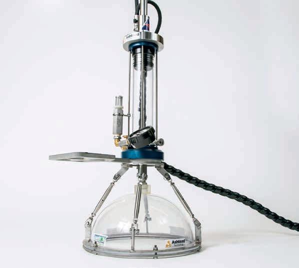
Cleaning tools
Manipulators
Hydraulic power pumps & reelers
Sampling tools
Intervention skids 09
Sampling
06
07
08
09
10
Section 9
tools
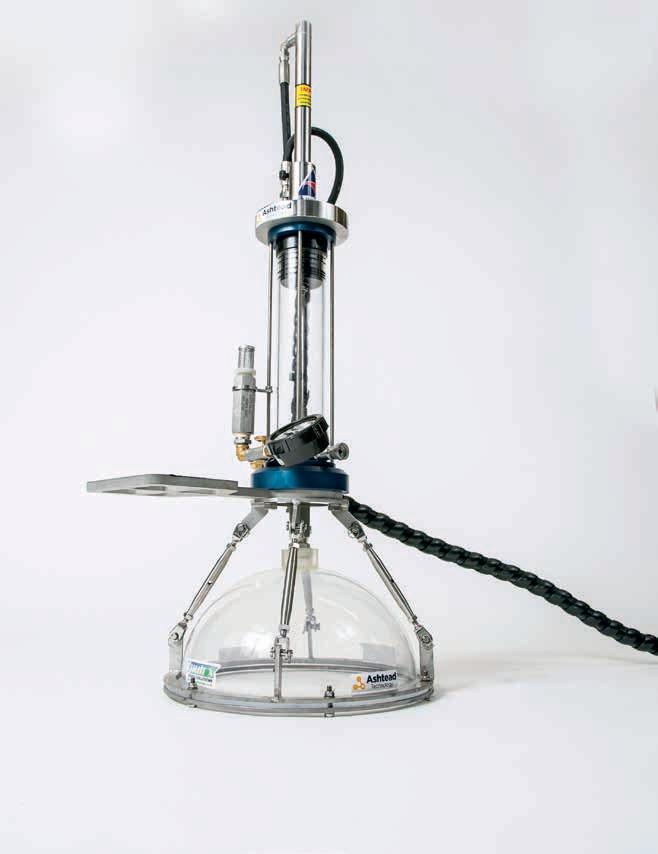
Applications
Capture, contain and recover liquid
Capture, contain and recover gas
Features
Robust stainless steel housing
Small high pressure bottles
4000m / 13,123ft depth rated
Can be deployed in work basket
ROV or diver operable
Primary & secondary product
isolation valves
Bleed off valve
In the box
Gas & Liquid Sampler
Rated sample bottles
Operations and maintenance manual
Vortex Gas & Liquid Sampler Mk ll
High pressure and rugged sampling tool
The vortex gas & liquid sampling tool is designed to capture and store gas or liquids escaping underwater for the purpose of recovery to the surface for analysis. The tool is designed to be deployed from the surface with zero pressure in the containment bottles. Sample filling relies on pressure differential between the isolated sea level pressure inside the bottles and the surrounding ambient sea water pressure.
All the components are housed in one anti-impact stainless steel housing, allowing this tool to be rough handled and transited in work baskets.
Personnel do not have to be directly exposed to pressurised components during recovery. Very high burst pressure bottles allow higher containment pressure in smaller bottles to reduce foot print of tool.
The tool features primary and secondary product isolation valves - plus a back up non return valve to further prevent product escaping after sample has been taken.
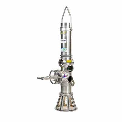
Vortex Gas & Liquid Sampler Mk ll
Specifications
Containment bottle volume
Potential gas sample volume
Potential liquid sample volume
Main relief valve setting
Main relief valve working range
Main isolation valve
Secondary isolation valve
Sample bleed off valve
Pressure gauge
Depth rating
Internal volume
Burst(min)
Puncture force
Working pressure
Dimensions of complete tool
Funnel diameter
Weight in air
Weight in water
1 litre / 0.475 gallon
5.1 cubic ft (146 litre) when stored at 69bar / 1200psi
1 litre / 0.475gal
124bar / 1800psi
0-207bar / 0-3000psi
Rated to 500bar / 7250psi
Rated to 207bar / 3000psi
Rated to 207bar / 3000psi
-200 to 2000psi
4000m / 13,123ft
445ml / 0.11gal min (each bottle)
599bar / 8700psi
260 Nf max *1
Design test pressure of 299bar / 4350psi marked service pressure 239bar / 3480psi
890 x 180mm diameter / 35in x 7in diameter
150mm / 6in
22kg / 48.5lbs
16kg / 35lbs
Applications
Capture, contain and recover liquid
Capture, contain and recover gas
Features
Robust stainless steel housing
Small high pressure bottles
4000m / 13,123ft depth rated
Can be deployed in work basket
ROV or diver operable
Primary & secondary product
isolation valves
Bleed off valve
Min 4 bottle hire
In the box
Gas & Liquid Sampler
Rated sample bottles
Operations and maintenance manual
Vortex Multi Sample Gas & Liquid Sampler
High pressure and rugged sampling tool
The vortex multi sample gas & liquid sampling tool is designed to capture and store gas or liquids escaping underwater for the purpose of recovery to the surface for analysis. The tool is designed to be deployed from the surface with zero pressure in the containment bottles. Sample filling relies on pressure differential between the isolated sea level pressure inside the bottles and the surrounding ambient sea water pressure.
All the components are housed in one anti-impact stainless steel housing, allowing this tool to be rough handled and transited in work baskets.
Personnel do not have to be directly exposed to pressurised components during recovery. Very high burst pressure bottles allow higher containment pressure in smaller bottles to reduce foot print of tool.
The tool features primary and secondary product isolation valves - plus a back up non return valve to further prevent product escaping after sample has been taken.
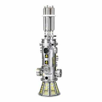
Vortex Multi Sample Gas & Liquid
Sampler Specifications
Sample
Containment bottle volume
Main relief valve setting
Main relief valve working range
Main isolation valve
Pressure gauge
Depth rating
Dimensions of complete tool
Funnel diameter
Weight in air
Weight in water
4
0.5 litre / 0.132 gallon
124bar / 1800psi
0-413bar / 0-6000psi
Rated to 413bar / 6000psi
0 to 5000psi
4000m / 13,123ft
1482mm x 344mm diameter / 58in x 13.5in diameter
318mm / 12.5in
63kg / 136lb
51kg / 112lb
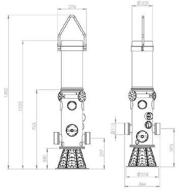
bottle qty
Applications
Capture, contain and recover liquid
Capture, contain and recover gas
Features
3000m / 9842ft depth rated
Mount to any ROV
Able to discharge sample subsea
2x 4 JIC hose pre-installed
In the box
Hydraulic Gas and Liquid Sampler
Rated sample bottle
Operational hoses
Operations and maintenance manual
Vortex Hydraulic Gas & Liquid Sampler
Low pressure, hydraulic operated sampling tool
The vortex hydraulic gas sampler is designed to capture and recover gas and liquid samples in a subsea environment. These samples are extracted in a low pressure state of no more than 14psi (0.96bar) by means of a hydraulic mechanical operated syringe which ingests then purges sample into a sample bottle. This tool is designed to be deployed from the surface with the syringe bled of air immediately upon entering the water. Sample filling relies on the suck and blow pumping motion created by the syringe and associated relief valves.
Samples taken can be discharged or cycled out of the syringe whilst under water if necessary. Discharging syringe into sample bottle typically captures 0.268l fresh water by volume with exhaust relief set at 12psi. Discharging syringe into sample bottle typically captures 0.523l of fresh air by volume with exhaust relief set at 12psi.
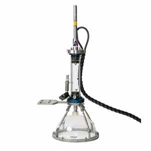
Vortex Hydraulic Gas & Liquid
Sampler
Specifications
Syringe cylinder volume
580ml / 0.153gal
Sample bottle volume 1 litre / 0.264gal
Main relief valve setting on syringe0.8bar / 12psi
Syringe body and end caps materialAcrylic
Piston material Acetal
Piston rings / seals material Nitrile 50 x 60 x 4
Piston cap o-rings material Nitrile N70
Depth rating
3000m / 9842ft
Containment bottle Internal volume445ml / 0.11gal min (each bottle)
Burst (min)
599bar / 8700psi
Puncture force 260 Nf max *1
Material body
Tubes EN 10305-1 material LBM spec
Material cap 12.0338 (St4)
Weight empty in air 10kg / 22lbs
Complete tool dimensions 940 x 460mm / 37 x 18.1in
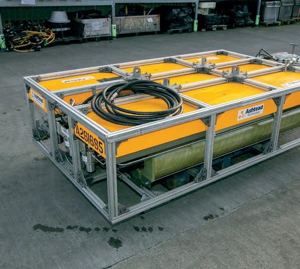
Cleaning tools
Manipulators
Hydraulic power pumps & reelers
Sampling tools
Intervention skids 10
Intervention skids
06
07
08
09
10
Section 10
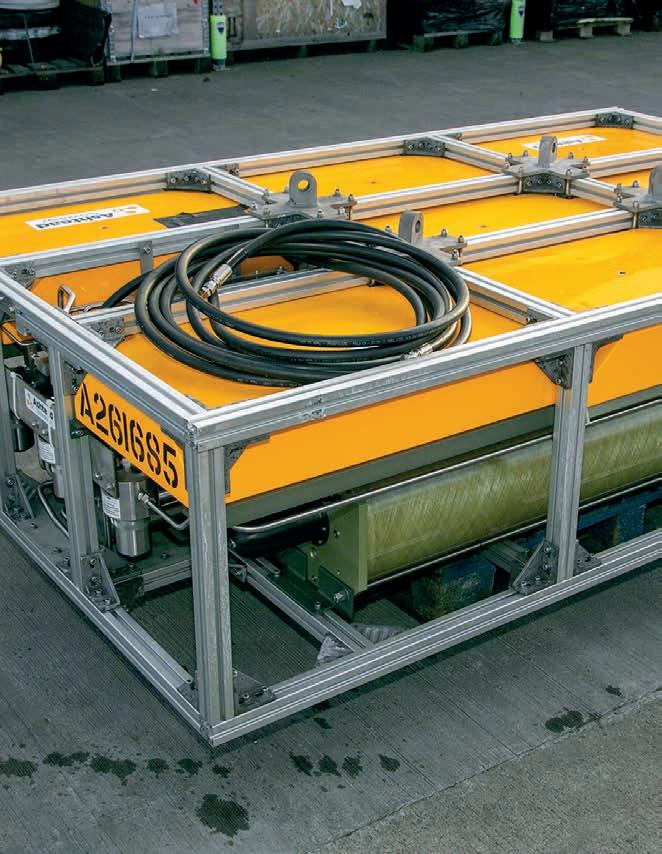
Applications
Multi-fluid injection operations BOP operations
Features
Aluminium frame skid
3,000m / 9842ft rated
Adaptors to fit most ROVs
In the box
Buoyancy
Protective grating
Slide rails for tooling cartridge Operations and maintenance manual
Multi-purpose ROV Skid
Modular skid systems
Multi-purose modular skid, ideal for many applications and requirements suitable for direct connection to most WROVs. All skids are designed and manufactured inhouse, using our own reliable modular system of construction, providing a simple and easy skid that when required is not complex to service, repair or modify.
If your next skid requirement is not listed within our standard builds please contact us directly for your quotation.
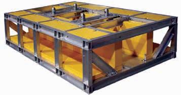
Multipurpose ROV Skid Specifications
Depth rating
3,000m / 9842ft
Construnction Aluminium
Skid configurations available IHPU skids, survey skids, docking skids, suction anchor skids and bespoke skids
Applications
Fluid transfer
Pressure testing
Hot Stab operations
Features
270 litre capacity
Integrates to any work class ROV
Max 10,000psi operating pressure
In the box
Fluid Injection Skid
Operational hoses
Comms tail
Operations and maintenance manual
Ashtead Technology ROV Fluid Injection
Skid
Multi-fluid injection skid
The fluid injection skid combines a standard ROV skid interface with a 10k IHPU system and adds two 135ltr piston style reservoirs.
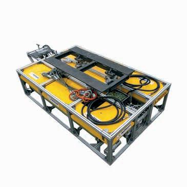
Ashtead Technology ROV Fluid
Injection Skid Specifications
Specifications:
Reservoir
Depth rating
Operating temperature
Max input pressure
Required input pressure
Max output pressure
Desired output pressure
Max input hydraulic flow
Max output hydraulic flow
ROV interface
Hydraulic connections
Comms connection
Mini TCU electrical power
Data communication
Skid dimensions:
Skid frame LxWxH
With front porch LxWxH
Weights:
Empty
Filled with oceanic HW740
2 x 135 litre / 36 gal piston style reservior
3,000m / 10,000ft
0 to +60°C / 32 to +140°F
207bar / 3,000psi
207bar / 3,000psi
690bar / 10,000psi
690bar / 10,000psi
60.6lpm / 16gpm
7.6lpm / 2gpm
T-type manipulator handle; 17H dual port 10ksi rated
Pressure - 8 JIC female
Return - 8 JIC female
Supplied with interface tail
18VDC - 28VDC
RS232
2450 x 1520 x 840mm
3015 x 1520 x 840mm
930kg (in air) / 90kg (in water)
1180kg (in air) / 90kg (in water)
Applications
Suction pile / anchor installation
Suction pile / anchor removal
Features
Efficient pump with superior flow
Erosion resistant impeller
Filtered suction into pump
Data feedback redundancy via
Perry USD and topside laptop
Integrated water flow meter
In the box
Vortex Anchor Boss Suction Pump
Topside computer
Perry subsea display
Relief valve springs
Pump spares kit
Operational hoses
Operations and maintenance manual
Vortex Anchor Boss Suction Pump Using the latest technology to reduce vessel time
The suction anchor system is a suction pump system that is designed to be mounted on the side, rear of the ROV or skid mounted.
The tool consists of the proven high flow vortex water pump, high flow suction and pressure relief valves, task specific water flow meter and Perry USD to display real time water flow and water pressure.
The anchor boss system is primarily used for suction pile / anchor installation and removal in addition to riser flushing applications where high water flow is required. The system uses the latest pump and flow technology which enables it to remain subsea for the duration of the pile installation. Other conventional systems require change out for low flow / high pressure pump which as a result increases vessel time.
Vortex Anchor Boss Suction Pump
Specifications
Minimum hydraulic pressure
60bar / 870psi
Maximum hydraulic pressure (Hyd motor)350bar / 5076psi
Maximum hydraulic flow 180lpm / 47.5gpm
Relief valve Adjustable from 0.3-8.0bar / 4.3-116psi
Maximum water flow 215m3 / hr with 180lpm / 47.5gpm at 248bar / 3596psi
Maximum pressure differential 9.5bar / 139psi
Connections
75mm / 3in ID hose
Weight in air 125kg / 275.5lbs
Materials Aluminium, stainless steel, thermoset epoxy resin
11
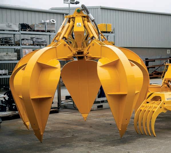
Grabs
Miscellaneous
11
11
12 Bags, matresses & baskets 13
ROV tools
Section
Grabs 14 Camera Boom Arms Inspection Camera’s
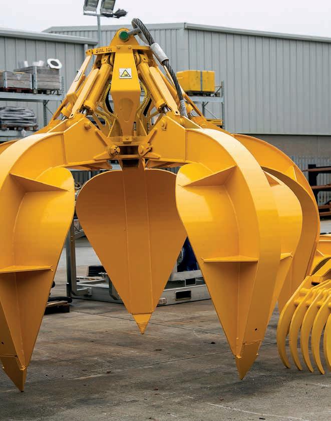
Applications
Pipe recovery
Decommissioning operations
Features
20 Te maximum lift capacity
Pressure gauge
Option hot stab for ROV-based hydraulic support
Grab bars for ROV-controlled positioning and stabilising
In the box
All required hoses
Operations & maintenance manual
Certificate of testing
Lifting Kit
On-deck support & weld plates
Spares kit
UCS Pipe Recovery Tool -
48" - 6m
For recovering large diameter sections of pipe from 6 metres length and upwards
The Pipe Recovery Tool 48” – 6m is designed to recover lengths of cut pipe from the seabed floor and return them to deck during decommissioning operations. The tool is designed to be crane-deployed and can recover lengths of pipe from ~6m upwards.
The tool consists of two large pipe-grabs positioned at either end of the tool, with a total SWL of 20,000 kg. It features a mounting panel with two quick connects for downlines, a pressure gauge, and a counterbalance valve to open and close the two grabs and ensure pressure can be ‘locked in’, allowing the grabs to remain open or closed if hydraulic supply is lost.
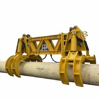
UCS Pipe Recovery Tool - 48" - 6m
Specifications
Maximum lift capacity
Flow rate
Maximum pressure
Hydraulic oil type
Length
Breadth (grabs open)
Height (grabs open)
Mass of tool in air
Mass of tool in seawater
Minimum pipe diameter for grabs
Maximum pipe diameter for grabs
20,000kg / 44,090lbs
50 l/min / 13.2 gal/min
170 bar / 2,500 psi
ISO VG32 (or equivalent)
5,988mm / 235.7in
2,853mm / 112.3in
3,179mm / 48in
11,500kg / 25,350lbs
8,480kg / 18,690lbs
200mm / 8in
1,220mm / 48in
Applications
Recovery of cut pipe lengths
Removal of subsea debris
Features
Single point lift
Topside or ROV controlled
In the box
All required hoses
Operation & maintenance manual
Certificate of testing
Lifting kit
Spares kit
Pipe Recovery Tool - 32" - Single Grab
For the recovery of pipe and debris from the seabed floor
The Pipe Recovery Tool - 32" - Single Grab is designed to recover cut lengths of pipe or debris from the seabed floor and return them to deck during decom operations. The tool is designed to be crane deployed and can recover lengths of pipe and/or debris of about ~ 0.5m in length.
The tool consists of one large pipe grab with a total SWL of 8 Te. A mounting panel provides two quick connects for downlines, a pressure gauge and a counterbalance valve to open & close the grab and ensure pressure can be ‘locked in’, allowing the grab to remain open or closed if hydraulic supply was to be lost.
The tool has a circular ROV grab bar at around the top of the tool. This is so that the tool can be positioned subsea by the ROV if required.
The Pipe Recovery Tool - 32" - Single Grab uses a single central pad eye for lifting the required load or debris.
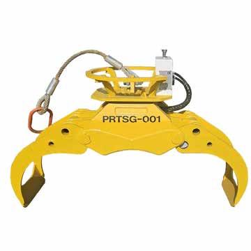
Pipe Recovery Tool - 32" - Single Grab
Specifications
Maximum lift capacity
Flow rate
Maximum pressure
Hydraulic oil type
Length
Breadth
Height (grabs closed)
Mass of tool in air
Mass of tool in seawater
Minimum pipe diameter for grabs
Maximum pipe diameter for grabs
8,000kg / 17,637lbs
70 l/min / 18.5 gal/min
210 bar / 3,045 psi
ISO VG32 (or equivalent)
1,056mm / 42in
750mm / 30in
866mm / 34in
458kg / 1,010lbs
387kg / 853lbs
100mm / 4in
800mm / 31.5in
Applications
Pipe recovery
Recover lengths of pipe from 2m upwards
Decommissioning operations
Features
16T maximum lift capacity
Single lift point
Pressure gauge and counterbalance valve
Option of adding third grab if required (12m only)
Grab bars for ROV positioning and stabilising
Option of hot stab for ROV-based hydraulic supply with 2m, 6m and 12m
In the box
All required hoses
Operations & maintenance manual
Certificate of testing
Sling set
On‐deck supports & weld plates
Spares Kit
UCS 2m - 12m Pipe Recovery Tool
Recover lengths of pipe from ~2m upwards
The Ashtead Technology Pipe Recovery Tool is designed to recover cut lengths of pipeline from the seabed floor and return them to deck during decommissioning operations. The tool, which is designed to be crane deployed, is available in 2m, 6m and 12m sizes and can recover lengths of pipe from 2m upwards.
The Pipe Recovery Tool consists of two large pipe grabs positioned at either end of a beam with a total safe working load (SWL) of up to 16T. A mounting panel with two quick connects for downlines, a pressure gauge and a counterbalance valve to open and close the two grabs and ensure pressure can be ‘locked in’, allowing the grabs to remain open or closed should hydraulic supply be lost. The 12m variant has an option of adding a third grab, positioned at the centre of the beam. This can be used to prevent flexing of the recovered pipe section during operations, if required.
The tool has two ROV grab bars at either end of the tool, enabling it to be positioned subsea by the ROV if required. The 6m and 12m variants also feature an ROV grab bar next to the mounting panel to stabilise the vehicle when viewing the pressure gauge.
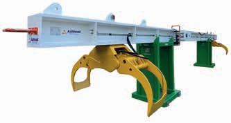
2m Pipe Recovery Tool
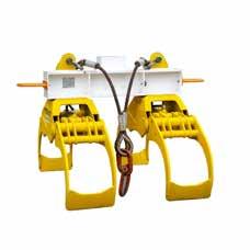
12m
16,000kg / 16T
70l/min / 18.5gal/min
270bar / 3,905psi
ISO VG32 (or equivalent)
12,550mm / 494in
1,056mm / 42in
1,142mm / 45in
2,504kg / 5,520lbs
2,170kg / 4,784lbs
½” quick connect ½” quick connect
Blue Logic DP receptacle, 10k, ½” BSP
6m
16,000kg / 16T
70l/min / 18.5gal/min
270bar / 3,905psi
ISO VG32 (or equivalent)
6,575mm / 259in
1,056mm / 42in
1,142mm / 45in
1,715kg / 3,781lbs
1,487kg / 3,278lbs
½” quick connect ½” quick connect
Blue Logic DP receptacle, 10k, ½” BSP
2m
16,000kg / 16T
70l/min / 18.5gsm
270bar / 3,905psi
ISO VG32 (or equivalent)
2,075mm / 82in
1,056mm / 42in
1,142mm / 45in
1,085kg / 2,292lbs
941kg / 2,075lbs
½” quick connect ½” quick connect
Blue Logic DP receptacle, 10k, ½” BSP
Maximum lift capacity Maximum flow rate
Hydraulic oil type
Maximum pressure Length Breadth Height (grabs closed) Mass (in air) Mass (in water) Pressure Return Hot stab
UCS 2m12m Pipe Recovery Tool Specifications
Applications
Rock grab
Boulder clearance
Debris clearance
Features
10 Te maximum lift capacity
Crane deployed
Custom handles available to optimise for project requirements
Single lift point
Mounting panel with 2 x ½” quick disconnects
Hydraulic counterbalance valve to ensure that grab remains open if hydraulic supply is lost
In the box
All required hoses
Operations & maintenance
manual
Certificate of testing
Lifting kit
Spares kit
Grab - Orange Peel - 10Te - 3.5m³ Move or recover boulders and debris from the seabed floor
The Grab – Orange Peel – 10Te – 3.5m³ is utilised to either move or recover boulders and other debris from the seabed floor. The tool is designed to be crane deployed and can recover boulders of up to 10 Te. Custom handles are also available to optimise the product to the demands of your project.
There is a single lift point on the centre of the grab, and a mounting panel with two ½” quick disconnects for use with downlines. A hydraulic counterbalance valve opens and closes the grab and ensures that pressure can be locked in. This allows the grab to remain open or closed if hydraulic supply is lost.
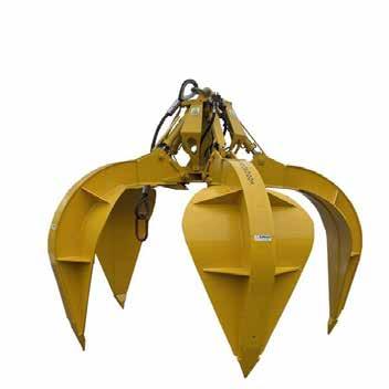
Grab - Orange Peel - 10Te - 3.5m³
Specifications
Maximum lift capacity
Grab volume
Flow rate
Maximum pressure
Hydraulic oil types
Number of tines
Diameter (grabs open)
Diameter (grabs closed)
Height (grabs open)
Height (grabs closed)
Mass of tool
10,000kg / 22,046lbs
3.5m³ / 124 feet³
70 l/min / 15.5 gal/min
270 bar / 3,915 psi
ISO VG32 (or equivalent)
5
3,440mm / 135in
2,500mm / 98in
3,000mm / 118in
3,250mm / 128in
3,250kg / 7,165lbs
Applications
Rock grab
Boulder clearance
Debris clearance
Features
5 Te maximum lift capacity
Crane deployed
Custom handles available to optimise for project requirements
Single lift point
Mounting panel with 2 x ½”
quick disconnects
Hydraulic counterbalance valve to ensure that grab remains open if hydraulic supply is lost
In the box
All required hoses
Operations & maintenance
manual
Certificate of testing
Lifting kit
Spares kit
Grab - Orange Peel - 5Te - 2.3m³ Move or recover boulders and debris from the seabed floor
The Grab – Orange Peel – 5Te – 2.3m³ is utilised to either move or recover boulders and other debris from the seabed floor. The tool is designed to be crane deployed and can recover boulders of up to 5 Te. Custom handles are also available to optimise the product to the demands of your project.
There is a single lift point on the centre of the grab, and a mounting panel with two ½” quick disconnects for use with downlines. A hydraulic counterbalance valve opens and closes the grab and ensures that pressure can be locked in. This allows the grab to remain open or closed if hydraulic supply is lost.
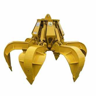
Grab - Orange Peel - 5Te - 3.5m³
Specifications
Maximum lift capacity
Grab volume
Flow rate
Maximum pressure
Hydraulic oil types
Number of tines
Diameter (grabs open)
Diameter (grabs closed)
Height (grabs open)
Height (grabs closed)
Mass of tool
5,000kg / 11,023lbs
2.3m³ / 81 feet³
70 l/min / 18.5 gal/min
270 bar / 3,915 psi
ISO VG32 (or equivalent)
6
2,600mm / 102in
1,600mm / 63in
2,000mm / 79in
1,760mm / 69in
1,700kg / 3,748lbs
Applications
Cable recovery
Cable removal
Features
Grips cables up to Ø100mm / Ø4in 23t maximum line pull
Industry standard tool
Robust construction
Lightweight aluminium design
In the box
Cable gripper
Jaw spacer
QD system
Jaw sets as standard
Operational hoses
Operations and maintenance manual
TA17 Cable Gripper Light weight cable gripper
The cable gripper forms the link between a recovery line from the surface vessel and a submarine cable when the cable is to be brought to the surface. The cable gripper is a powerful jaw mechanism with a lifting eye. The jaw is set hydraulically and then remains mechanically locked (by an over centre mechanism) after the hydraulics are removed. It is therefore highly suitable for operation by remotely operated vehicles (ROVs).
The gripper consists of one static and one hinged jaw. It is closed and opened by a hydraulic ram. A choice of jaw sets provides the necessary flexibility to enable the gripper to handle cable of varying sizes up to 100mm in diameter.
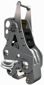
TA17 Cable Gripper
Specifications
Pull (maximum)
23t (this is line load-not SWL)
Cable type Armoured or lightweight
Maximum hydraulic pressure 210bar / 3045psi
Cable diameter
Hydraulic fluid
Weight in air
Weight in water
17-100mm / 0.66-4in
Mineral oil
35kg / 77lbs
25kg / 55lbs
Hoses 2 x 4 JIC
Applications
Cable recovery
Features
No hydraulics required
3t working load limit
Maximum cable diameter 110mm
In the box
ETA 3T Mechanical Cable Gripper
Operations and maintenance manual
ETA 3T Mechanical Cable Gripper
For the recovery of armoured or lightweight cables
The cable gripper has been designed by ETA for the recovery of armoured or lightweight cables in a subsea environment. The gripper has a working load limit of 3.0t in Sea State 6. The gripper can recover cables of a variety of diameters however, the anvils must be set to the correct position for a particular diameter.
The gripper is normally attached to a subsea cable by an ROV. Before deployment, a line should be connected between the vessel & the gripper top shackle. This will be used for hoisting the gripper to the surface.
The gripper is passive & requires no power from the ROV. It is deployed using an ROV manipulator arm attached to the handle at the top. At the bottom of the gripper, there is an open plate between which are two spring loaded gates (anvils). The gripper should be lowered onto a cable using the manipulator arm until the cable opens the anvils. Once the cable has passed between the anvils they will slam shut & hold the cable within the gripper.
The ROV can now release the gripper & the unit can be hoisted to the surface. As tension is applied from the line to the top shackle, the internal mechanism of the gripper pushes a clamp down to rigidly hold the cable in position. This allows the gripper & cable to be safely hoisted to the surface.
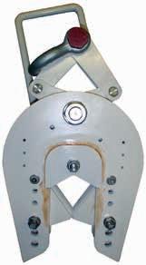
ETA 3T Mechanical Cable Gripper
Specifications
Working load limit
3.0t in sea state 6
Maximum cable diameter Ø110mm / Ø4.3in
Minimum cable diameter Ø15mm / Ø0.5in
Height 675mm / 26.5in (clamp retracted)
755mm / 29.7in (clamp extended)
Width 350mm / 13.7in
Depth 170mm / 6.6in
Weight in air 55kg / 121lbs
Weight in water 48kg / 105lbs
Material Steel & stainless steel
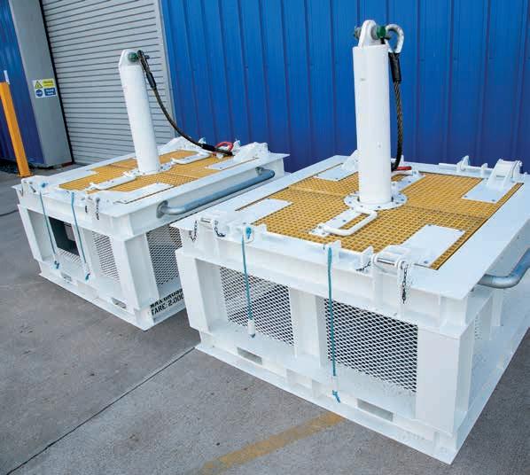
11 Grabs
12 Bags, matresses & baskets
12
13 Miscellaneous ROV tools
Section 12 Bags, matresses & baskets
14 Camera Boom Arms
Inspection Camera’s
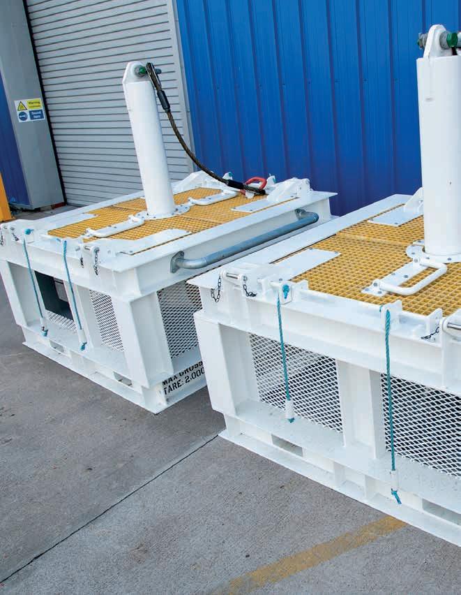
Applications
Heavy duty use
Features
Certified to requirements
Capacity from 1t-40t
Customised and standard subsea baskets can be provided
WeSubsea HD Pipeline Recovery Baskets
Customised and standard subsea baskets
Ashtead Technology’s WeSubsea Heavy Duty Pipeline Recovery Baskets are certified to requirements, and range in capacity from a 1 ton to 40 ton payload. Our subsea construction baskets are available in customised and standard configurations.
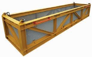
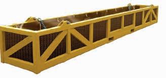 PRB Model 1, 30ft
PRB Model 2, 20ft
PRB Model 1, 30ft
PRB Model 2, 20ft
WeSubsea HD Pipeline Recovery Baskets
Specifications
External size (LxWxH)
Internal size (LxWxH)
30ft
10500 x 2560 x 1860mm
10235 x 2150 x 1390mm
Payload 15000kg/16700kg
Weight 5500kg/8300kg
Rigging
Access
2 part chain sling to master link per slide
External/internal ladder for safe access
6260 x 1190 x 980mm
6080kg 1920kg
2 part chain sling to master link per slide
PRB model 1,
PRB model 2, 20ft
Applications
Heavy duty use
Features
Certified to requirements
Capacity from 1t-40t
Customised and standard subsea baskets can be provided
WeSubsea HD Debris Baskets
Customised and standard subsea baskets
Ashtead Technology’s WeSubsea Heavy Duty 20ft Construction Baskets are certified to requirements, and range in capacity from a 1 ton to 40 ton payload. Our subsea construction baskets are available in customised and standard configurations.

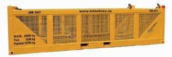 HDD Model 1, 20ft
HDD Model 2, 20ft
HDD Model 1, 20ft
HDD Model 2, 20ft
WeSubsea HD Debris Baskets
Specifications
External
Internal size (LxWxH)
6055 x 2435 x 1401mm
5700 x 2100 x 930mm
Payload 15140kg
Weight 4360kg
Access 2 side hatches
6058 x 2438 x 1438mm
5738 x 2114 x 1220mm
14975kg / 16760kg
3475kg / 3240kg
2 part chain sling to master link per slide
size (LxWxH)
HDD model 1, 20ft
HDD model 2, 20ft
Applications
Heavy duty use
Features
Certified to requirements
Capacity from 1t-40t
Customised and standard subsea baskets can be provided
WeSubsea HD Well Intervention Baskets
Customised and standard subsea baskets
Ashtead Technology’s WeSubsea Heavy Duty Well Intervention Baskets are certified to requirements, and range in capacity from a 1 ton to 40 ton payload. Our subsea construction baskets are available in customised and standard configurations.
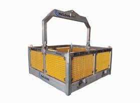
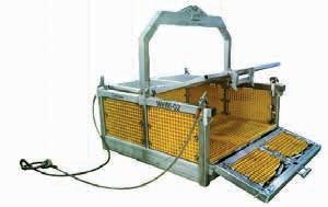 WIB Model 1
WIB Model 2
WIB Model 1
WIB Model 2
WeSubsea HD Well Intervention
Baskets
Height
Payload
Included
Slide
size (LxWxH) 1,660 x 1,660 x 765mm
size (LxWxH) 1,500 x 1,500 x 530mm
Specifications External
Internal
1755mm
3,000kg WIB model 1 WIB model 2
to top of mastermilk Bail arm
Weight
500kg Optional Height
/ wire sling bridle
to top
of bail arm
-1,660 x 1,660 x 765mm 1,500 x 1,500 x 530mm 1755mm
2,800mm 3,000kg 600kg Bail arm / wire sling bridle
door
and two fold lid
Applications
ROV friendly
Storing of ROV tooling
Recovery of subsea debris
Storage of jumper cables and hoses
Deployment of diver tooling
Features
Certified to requirements
5.0Te payload
1.8 Cubic metre subsea basket
ROV friendly lockable split folding lid
Can be supplied with detachable galvanished hand rails
In the box
Basket
Certified sling set
Harper Type 30 Subsea Basket
ROV Friendly Subsea Basket
Harper Type 30 Subsea Baskets are an ROV friendly subsea basket and has a payload of 5.0Te. The basket is supplied with an ROV friendly lockable split folding lid. The basket can also be supplied with detachable galvanised hand rails. Subsea baskets are certified to requirements.
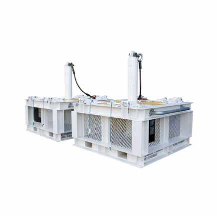
Harper Type 30 Subsea Basket
Specifications
External size (LxWxH)
2000 x 2264 x 2163mm
Internal size (LxWxH) 1593 x 1593 x 727mm
Payload 5.0Te
Weight 2.0Te
Access Lid fitted to top of basket
Rigging Single leg wire rope sling assembly
Applications
Lifting concrete mattresses
Features
Certified to handle concrete mattresses
Maximum weight 24000kg
Gross weight 1500kg
Footprint (LxW) 6000mm x 2200mm
WeSubsea Mattress Deployment Tool
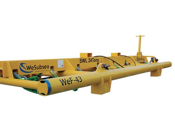
WeSubsea Lifting Frame for Concrete Mattresses
Easy to use and certified
Ashtead Technology’s easy to use and certified WeSubsea lifting frames are designed to effectively handle concrete mattresses up to a maximum weight of 24000kg.
Concrete mattresses
The concrete mattress is manufactured with the maximum quality concrete available, moulded into block mattresses with a Danline 14mm / 22mm UV stabilized polypropylene rope (dependent on dimensions). It is designed with a brick pattern matrix and offers a high degree of flexibility permitting it to follow the contours of the pipeline, umbilical and seabed.
LxWxH: 6000mm x 3000mm x 150mm Weight: 4900kg
LxWxH: 6000mm x 3000mm x 300mm Weight: 9800kg
We can also design special mattresses of different types and sizes according to requirements.
• Mattresses with centre element.
• Mattresses with PE-HD 500 plates

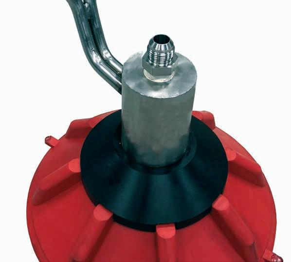
Grabs
Bags, matresses & baskets
Miscellaneous ROV tools 13
Miscellaneous ROV tools
Camera
11
12
13
Section 13
14
Boom Arms Inspection Camera’s
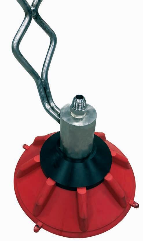
Applications
Subsea ROV operations
Features
Aluminium construction
Two off ISO 13628-8 docking latches
Weight in air 25kg / 55.1lbs 210bar / 3045psi working pressure
In the box
XLX ISO Docking Beam
2 ISO docking latches
Operational hoses
Operations and maintenance manual
Ashtead Technology ISO Docking Beam
Ideal for docking ROV to subsea structures
The docking beam is bolted to the front of an XLX vehicle and is used to dock onto subsea structures. The beam is supplied complete with two ISO13628-8:2002 fig 7 docking latches. The beam includes two anodes and all hoses to connect to an aux function on the ROV.
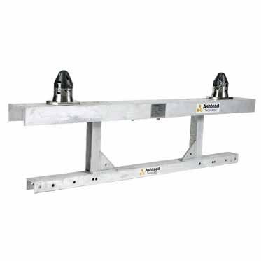
Ashtead Technology ISO Docking
Beam Specifications
Interface
Hydraulic input pressure
Hydraulic flow range
Depth rating
Weight in air
Materials
Latch / unlatched
ISO 13628-8 fig 7
210bar / 3045psi
2-10lpm / 0.5-2.6gpm
3000m / 9842ft
25kg / 55.1lbs
Aluminium, stainless steel, acetal 2 x 4 JIC hoses supplied
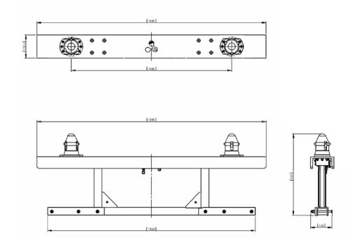
Applications
Subsea ROV operations
Features
High level of grip
300mm / 11.8in diameter suction cup
Suction cup mounted on lockable swivel
In the box
Attachment arm with foot
Low pressure pump
Control manifold
Operational hoses
Operations and maintenance manual
ROV Suction Foot
Ideal for securing ROVs against subsea structures
The suction foot can hold an ROV to smooth surfaces such as ship hulls, submarines, platform tubulars and pipelines. The high level of grip makes it suitable for a wide range of inspection and cleaning ROV tasks.
The attachment arm is a three function manipulator consisting of shoulder pitch, jaw and extend. The arm may be used in addition to standard ROV manipulators or as a low-weight substitute manipulator.
The foot has a flexible polyurethane moulded cup, tolerant of marine growth and crustaceans, and able to attach to curved surfaces down to 400mm (16in) diameter. The cup is abrasion and tear resistant. The cup is mounted on a ball swivel joint to ease self-alignment on the target surface. The swivel can be hydraulically locked once suction is achieved, for greater rigidity.
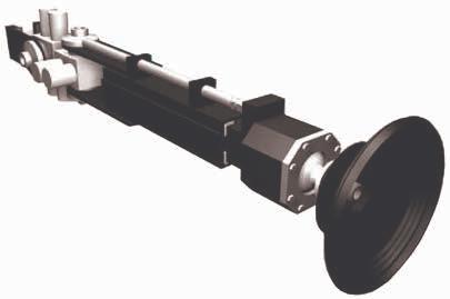
ROV Suction Foot
Specifications
Suction Foot OD workpiece diameter300mm / 11.8in
Workpiece diameter Flat to 400mm / 15.7in diameter
Ball joint reistance 1100Nm at 50bar / 725psi
Suction force 1950kgf at 3bar / 43.5psi
Suction force 720kgf at 1bar / 14.5psi
Weight in air 45kg / 99.2lbs
Weight in water 35kg / 77.1lbs
Lift at maximum reach 56kg / 123.4lbs
Maximum reach 1680mm / 66.1in
Extend 330mm / 13in
Shoulder yaw & pitch 180 degrees
Hoses 12 x 4 JIC hoses 1 x 1" medusa hose, 4m long
Applications
Subsea ROV operations
Features
High level of grip
Integrated fish tail handle
300mm / 11.8in diameter suction cup
Polyurethane cup
In the box
Manipulator held suction cup
Low pressure pump (optional)
Operational hoses
Operations and maintenance manual
Manipulator Held Suction Cup
Ideal for securing ROVs against subsea structures
The suction foot can hold an ROV to smooth surfaces such as ship hulls, submarines, platform tubulars and pipelines. The high level of grip makes it suitable for a wide range of inspection and cleaning ROV tasks.
The foot has a flexible polyurethane moulded cup, tolerant of marine growth and crustaceans, and able to attach to curved surfaces down to 400mm (16in) diameter. The cup is abrasion and tear resistant.
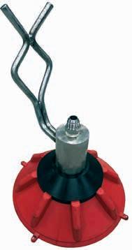
Manipulator Held Suction Cup
Specifications
Suction Foot OD workpiece diameter300mm / 11.8in
Workpiece diameter Flat to 400mm / 15.7in diameter
Suction force 1950kgf at 3bar / 43.5psi
Suction force 720kgf at 1bar / 14.5psi
Weight in air 7.7kg / 16.9lbs
Dimensions
300 x 300 x 460mm / 11.8 x 11.8 x 18.1in
Material Stanless steel, polyurethane, acetal
Hoses 1" medusa hose, 4m long
Applications
Guidepost removal
Guidepost disconnection
Features
Industry standard
Robust construction
Integrated flow divider for smooth operation
Multiple guidepost configuration
In the box
GL4 Regan Latch Tool
ROV handle
Operational hoses
Operations and maintenance manual
GL4 Regan Latch Tool Release tool for subsea guideposts
The GL4 Regan Latch release tool is used for the disconnection and removal of subsea guideposts.
In the past, most guideposts were permanent, and had to remain in place if damaged or in need of repair. The regan latch release tool, designed to be held in the ROV manipulator, enables an ROV to mechanically attach to the top of a guidepost and enable its removal using hydraulic power to compress and disengage the latching mechanism that holds the guidepost in place. The damaged or non-functional guidepost can then be retrieved to the surface along provided guide wires.
The GL4’s hydraulic supply can be either plumbed directly to the ROV, or supplied in the form of a hot stab attachment
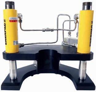
GL4 Regan Latch Tool
Specifications
Input pressure 207bar / 3000psi
Input flow 7.5lpm / 2gpm
Release force 8164kg / 18,000lbs
Stroke 75mm / 3in
Materials 316L stainless steel, carbon steel or aluminum
Weight in air 16kg / 35lbs
Weight in water 13kg / 28lbs
Hoses 2 x 4 JIC
Applications
Pumping operations
Injection operations
Features
Flow range 0-20lpm / 0-5.2gpm
Pressure rating 690bar / 10,000psi
max
Rated to 3000m / 9842ft ocean
depth
Complete system mounted in compact unit
In the box
Universal subsea display
Battery pack
Flowmeter & transducer
Flowmeter to USD cable
Mounting plate for system
Battery charger
Programming cable and software
Battery pack to USB cable
USD to ROV flying lead
Operations and maintenance manual
Flow Meter System
High pressure flow meter
The 0-20lpm 690bar flow meter system combines a flow meter with a standard universal subsea display to locally display a flow value subsea. The flow meter is rated to a maximum of 690bar working pressure and 20lpm maximum flow. The system is supplied with a battery for powering the display, but the unit can also be supplied power direct from the ROV, there is a flying lead supplied in the kit to allow for this option.
The USD uses ultra-efficient LED types, a very low power processor and sophisticated power switching regulators which, together, mean it can operate from a wide DC voltage input range, requiring very low current and equally able to operate from ROV supply or from battery. In addition, it has a software configurable sleep mode with option to wake up on sensor activity or from the light sensor on the front face.
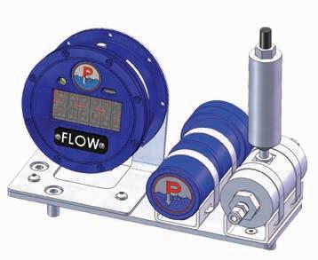
Flow Meter System
Specifications
Depth rating
Flow range
Max pressure rating
3,000m / 9842ft
0-20lpm / 0-5.2gpm
690bar 10,000psi
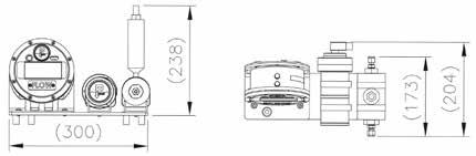
Winch
ROV-mounted camera winch
14
11 Grabs
Vortex camera winch is designed to be mounted on a ROV to allow a camera deployed vertically for visual inspection purposes. This is achieved via a lightweight

13 Miscellaneous ROV
12 Bags, matresses
& baskets
tools
14 Camera boom arms
inspection camera’s
Section 14
Camera boom arms inspection camera’s
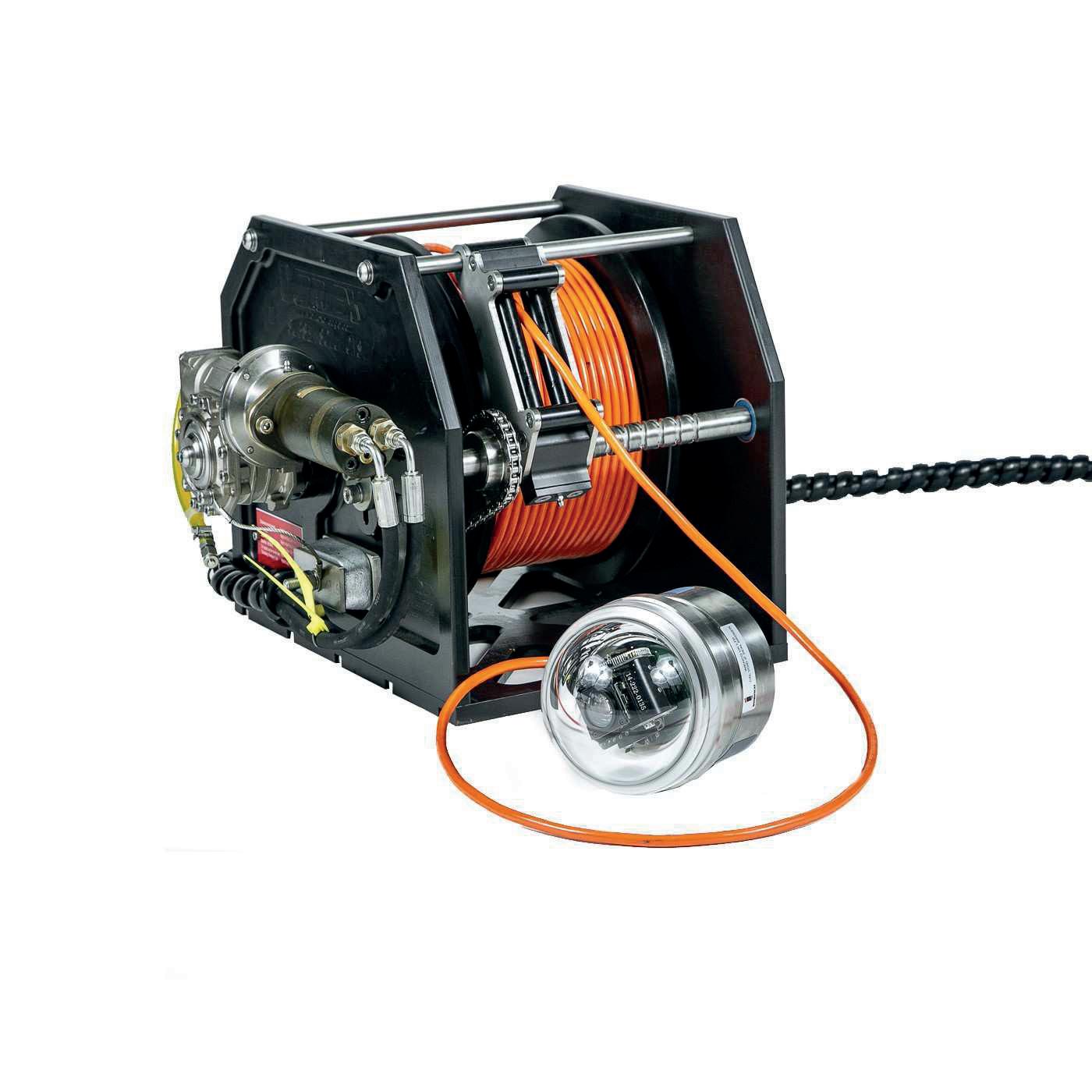
Applications
Pipe inspection
Vertical inspection
Well head inspection
Features
ROV or topside hydraulics
compatible
Heavy duty worm gearbox
50:1 gear ratio
Stainless steel and acetal
construction
Depth rated to 3000m
Roller fairlead
55m cable length
Plug and play
In the box
Vortex Heavy Duty Camera
Winch
Camera mount
Spares package
Operating instructions
Vortex Heavy Duty Camera Winch
Rugged ROV-mounted camera winch
The Vortex Heavy Duty Camera Winch is designed to be mounted on a ROV to allow a camera to be deployed vertically for visual inspection purposes. This is achieved via a heavy duty underwater hydraulic winch utilising a versatile 55m long
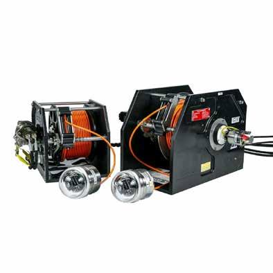
Vortex Heavy Duty Camera Winch
Specifications
Rated line pull 180kg / 442lbs at 11th layer of cable with 1000psi at motor
Minimum hydraulic flow 16lpm / 4.2gpm
Optimised hydraulic flow 20lpm / 5.3gpm
Minimum operation pressure 70bar / 1000psi
Maximum operation pressure 103bar / 1500psi
Hydraulic motor OMM32 31.6 or 1.93 in3 / rev
Geat train Worm drive gearbox to stainless chains and sprockets
Gear ratio
Drum barrel diameter
50:1
214mm / 8.4in
Drum flange diameter 400mm / 16in
Distance between flanges 166mm / 6.5in
Recommended cable size 9mm +/- 0.1mm
Weight in air 59kg / 130lbs
Weight in water 39kg / 86lbs
Dimensions 650mm / 25.5in x 550 / 21.6in x 528mm / 21in
Camera Various camera options available
Camera connector Burton 55A1-1508-0000C
Hoses 2 x 4 JIC
Applications
Pipe inspection
Vertical inspection
Well head inspection
Features
Lightweight and compact
55m cable length
Plug and play
In the box
Vortex Camera Winch
Camera mount
Spares package
Operating instructions
Vortex Medium Duty Camera Winch
ROV-mounted camera winch
The Vortex camera winch is designed to be mounted on a ROV to allow a camera to be deployed vertically for visual inspection purposes. This is achieved via a lightweight
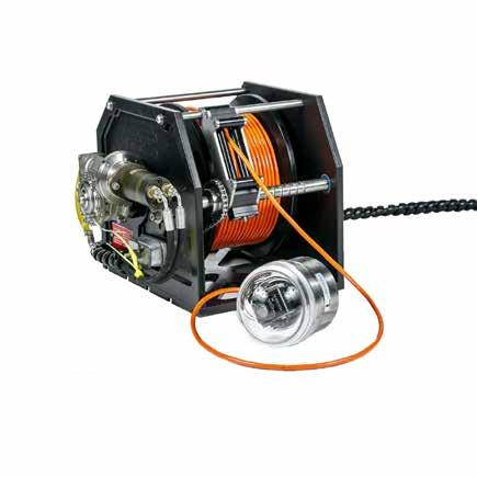
Vortex Medium Duty Camera Winch
Specifications
Flow rate requirement
16lpm / 4.2gpm to 30lpm / 7.8gpm
recommended 20lpm / 5.3gpm
Pressure 103bar / 1500psi to 2017bar / 3000psi
recommended 138bar / 2000psi
Weight in air 31kg / 68lbs
Weight in water 15kg / 33lbs
Camera Imenco Silvertip Shark (not included)
Camera connector Burton 55A1-1508-0000C
Hoses 2 x 4 JIC
Applications
Subsea inspection operations
Features
Range of configurations available
Fish tail handle
High resolution colour 650 TVL 10bit digital processing
With 6 integral high intensity LEDs
54° diagonal angle of view in water 4000m / 13,123ft depth rated titanium housing
In the box
Camera in mounting
ROV handle
3m / 9.8ft cable
Extension tube
Operations and maintenance manual
ROV Inspection Camera
4000m depth rated subsea inspection camera
The ROV camera is used for inspection of difficult locations. The camera is mounted in plastic outer casing to prevent damage to seal hubs. A colour camera with local ring LED light source is mounted in a plastic housing with a fish tail style handle for manipulation by the ROV. The camera is supplied with three joints and two lengths of camera tube to suit the specific application.
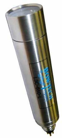
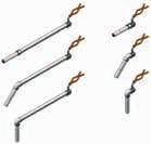
ROV Inspection Camera
Specifications
Horizontal resolution
Scanning
470 TV lines - PAL
625 line/0Hz - PAL
Video output Composite, 1.0V peak to peak into 75ohm
Focus control Fixed, 75mm / 3in to infinity
Field of view in water
Power input
Electrical connector
Depth rating
Cable
Camera material
54° diagonal
11-30VDC, 310 mA (max)
Sea-Conn BH-4-MP 4000m / 13,123ft
4m / 13.1ft SeaConn connecting cable
Titanium body
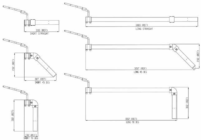
Applications
Underwater inspection
Equipment and tool placement
Target identification & classification
Monitoring operations
Features
Designed for inspection of pipelines up to 1 metre
Camera position stable throughout entire 120° angular movement of arm
Camera mount can be tilted through 120° and rotated through 360°Uses HLK-2150 pan & tilt
In the box
Boom arm
Operational hoses
Tilt, pan & tilt (optional depending on set up - 2,3 or 4 function)
Operations and maintenance manual
Hydro-Lek ROV Function Boom Arm
2, 3 and 4 function boom arm
The HLK-4600 camera boom arm has been designed for pipeline inspection work. Using a pair of these arms, pipelines of up to 36” can be easily inspected. Its unique design allows the camera mount to stay at the same angle through the entire 120° of angular movement of the arm. The camera mount can be tilted through a 120°. The arm uses Hydro-Lek’s standard HLK-1300 hydraulic cylinders.
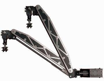
Hydro-Lek ROV Function Boom Arm
Specifications
Length of arm 1625mm / 64.3in
Height 310mm / 12.2in
Width 120mm / 4.7in
Up / down 70-0-50º
Left / right 90-0-30º
Camera tilt / roll
Weight in air
Weight in water
Materials
Ports
Hoses
3 function
4 function
60-0-60º
16kg / 35lbs
11kg / 24lbs
316 stainless steel
HE 30 hard anodised aluminium
Polyethylene
1/8” NPT – 7/16” SAE
2 x 4 JIC (pitch)
2 x 4 JIC (yaw)
2 x 4 JIC (tilt)
3 x 4 JIC (pan) + case drain
Applications
Detect leaks from subsea infrastructure
Pipeline or flow line pressure testing can be monitored
Detect cement returns during casing cementing operations, using a tracker dye which is added to the seawater spacer or to the cement from a distance of several metres (depending on dye concentration)
Features
Rhodamine, Fluorescein or Ultraviolet dye detection
Focused beam and filtered high intensity LEDs
Light amplification and photo detection technology
OceanTools DyeTector ®
ROV mounted subsea leak and dye detection system
DyeTector’s are an advanced subsea leak, dye and cement detector developed by OceanTools to detect rhodamine, fluorescein and ultraviolet dyes. The ROV mounted OceanTools DyeTector may be used to detect leaks from subsea infrastructure such as manifolds, wellheads or pipelines if a suitable dye has been added to the infrastructure fluids.
High intensity LED light is focused through lenses and filters to create a concentrated beam that is tuned to a specific wavelength to cause maximum molecular agitation of the dye. A sophisticated optical multiplier employs light amplifications technology to detect the specific dye from the agitated dye molecules. Advanced detection electronics convert the measurements to digital data.
Detection can be carried out at a safe working distance. Advanced ambient light suppression technology allows the DyeTector to be used in high levels of background light and also means the ROV’s lights do not need to be turned off. If required, dye can also be supplied with the unit
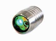

D7
OceanTools can also supply dyes that have been developed by Subsea Chemistry Ltd to precisely match the characteristics of the DyeTector making it the most effective subsea dye detecting system and dye available.
D8 D10
DyeTector ®
OceanTools
Specifications
D10
Ultraviolet
Fluorescein
Rhodamine
360-370nm 410-450nm
450-460nm
520-530nm
510-520nm
570-590nm
Up to 10m
18-36VDC
1A @ 24VDC Glenair G5507-1508
RS232 / RS485 ROV mounted 4000m Titanium Sapphire glass 155mm 101mm 3.1kg 1.8kg
Ultraviolet
360-370nm
410-450nm
D8
Rhodamine
520-530nm
570-590nm
Up to 10m
18-36VDC 01A @ 24VDC ROV mounted
RS232 / RS485
Glenair G5507-1508 4000m Titanium Sapphire glass 175mm 98mm 3.4kg 2.2kg
D7
Ultraviolet
Fluorescein
Rhodamine
360-370nm
450-460nm 520-530nm
410-450nm
510-520nm
570-590nm
Up to 10m 18-36VDC 0.5A @ 24VDC Glenair G5507-1508
RS232 / RS485 ROV mounted 6000m Titanium Sapphire glass 174mm 98mm 3.0kg 1.9kg
Target dye
Excitation wave-length
Detection wave-length
Detection range
Input voltage ROV or diver
Maximum current Data communications
Standard connector
Depth rating
Housing material
Window material
Length (excl connector)
Maximum diameter
Weight in air
Weight in water
15
Fast Winch 20Te
deployment, over boarding and general pulling
Section 15 Lifting, pulling and deployment
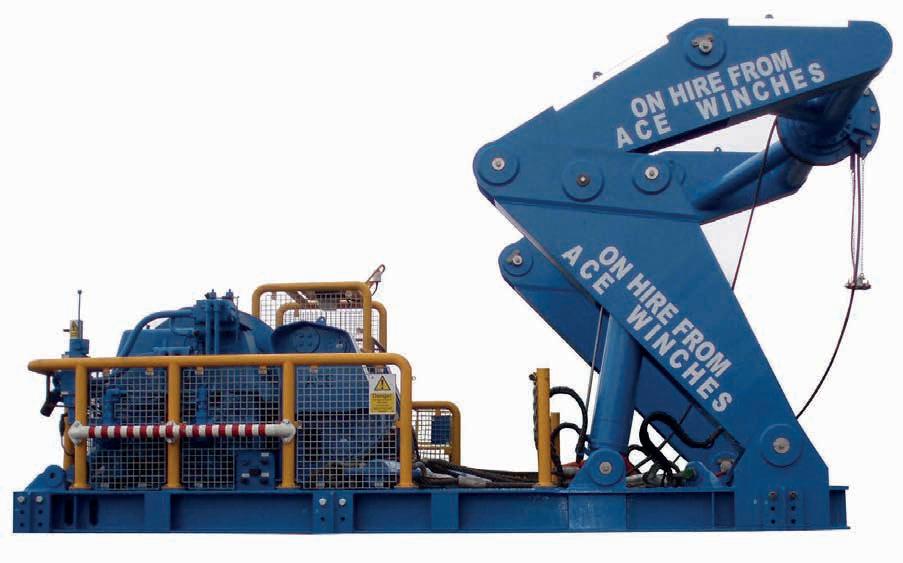
11 Grabs
& baskets
12 Bags, matresses
13 Miscellaneous ROV tools
inspection camera’s
14 Camera boom arms
and deployment
15 Lifting, pulling

Applications
Subsea lifting and deployment
Features
Mounted on a single skid
A-Frame and Fast Winch Range from 6Te to 20Te
Designed for use in hoisting, deployment, over boarding and general pulling applications.
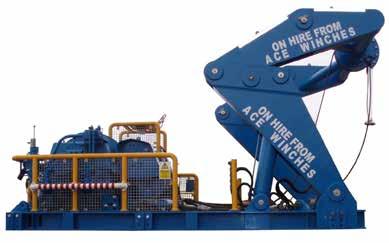
A-frame and Fast Winch
Specifications
15Te winch and A-frame package
Overall dimensions
Maximum wire rope capacity
Maximum gross weight
Overboard reach
6635mm
2000m of 28mm
40,000kg 3m
Operational area Safe area only
L x 4400mm W x 4315mm H
Applications
Mooring systems for FPSO, barges and other vessels
Topsides and jacket load-out/ installation
SURF installation
Pipelay and trenching operations
Offshore and subsea construction support
Wind turbine installation
Cable lay
Decommissioning and salvage
Abandonment and recovery
Dive bell and ROV support
Features
Single drum and double drum options
Suitable for wire rope from 10mm to 76mm
Bespoke design and manufacturing available
Hydraulic Drum Winch
Working load limits from 2 Tonne - 75 Tonne
Standard and bespoke drum winches designed for hoisting, deploying, mooring and general pulling applications. Drum winches can be supplied with our proven active heave compensation control system.
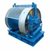
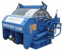
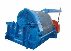
Hydraulic D rum W inch
Specifications
5075 Tonne
3610mm L x 3280mm
W x 2230mm H
1434m of 44mm
12,000kg
27,000kg
50 Tonne
3450mm L x 2870mm
W x 2190mm H
803m of 38mm
12,600kg
23,000kg
20 Tonne
1395mm L x 1811mm
W x 1325mm H
386m of 28mm
3095kg
6000kg
8.5 Tonne
1570mm L x 1150mm
W x 1210mm H
740m of 19mm
2000Kg
3500Kg
8.5 Tonne (first layer pull)20 Tonne (first layer pull)50 Tonne (first layer pull)75 Tonne (first layer pull)
Single drum
Over spooling
Single drum
Under spooling at 0° from horizontal
Single drum
Under spooling at 0° from horizontal
Single drum
Under or over spooling
Overall dimensions
Maximum wire rope capacity
Tare weight (excluding wire rope)
Maximum gross weight
Working load limit
Drum configuration
Wire exit position
Further assets are available. Scan the QR code for more information.
Applications
Mooring systems for FPSO, barges and other vessels
Topsides and jacket load-out/ installation
SURF installation
Pipelay and trenching operations
Offshore and subsea construction support
Wind turbine installation
Cable lay
Decommissioning and salvage
Abandonment and recovery
Dive bell and ROV support
Features
Single drum and double drum options
Suitable for wire rope from 10mm to 86mm
Bespoke design and manufacturing available
Hydraulic Drum Winch
Working load limits from 75 Tonne - 200+ Tonne
Standard and bespoke drum winches designed for hoisting, deploying, mooring and general pulling applications. Drum winches can be supplied with our proven active heave compensation control system.
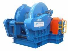
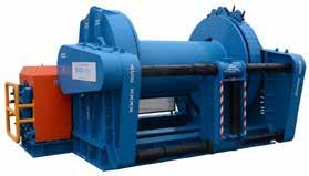
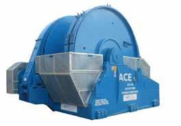
Winch
Hydraulic Drum
Specifications
250 Tonne
6295mm L x 4220mm W x 4320mm H
2300 of 64mm
65,000kg
125,000kg
250 Tonne (first layer pull)
120 Tonne
3239mm L x 4244mm W x 2575mm H
1016m of 52mm
28,000kg
52,000kg
120 Tonne (first layer pull)
Single drum
Under spooling at 0° from horizontal
90 Tonne
3740mm L x 3135mm W x 2662mm H
600m of 52mm
20,550kg
30,000kg
90 Tonne (first layer pull)
Single drum
Under spooling at 0° from horizontal
Overall dimensions
Maximum wire rope capacity
Tare weight (excluding wire rope)
Maximum gross weight
Working load limit
Single drum
Under spooling at 0° from horizontal
Drum configuration
Wire exit position
Further assets are available. Scan the QR code for more information.
Applications
Land based shore pulls
Offshore wire rope deployment and recovery operations
Landfall
Pipe-pulls
Construction
Salvage
Direct pulling operations
Features
Maintain constant wire rope pulling force over full length of pull
Grippers lock on the wire rope automatically if power fails
Straight line pulling action extends wire rope life
Accomodates large diameter wire rope sizes
Socket passing capability available
Linear Winch Working load limits up to 800Te
Engineered, designed and manufactured for a wide variety of applications requiring high-line pulls. Our linear winches offer a higher line pull-to-weight ratio than conventional styles of winches. Patent approved automatic socket passing is available for bespoke manufacturing.
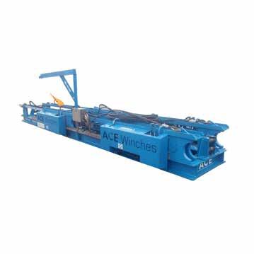
800 Tonne
17442mm L x 3517mm
W x 2113mm H
550 Tonne
8620mm L x 2885mm
W x 1635mm H
120,000kg
1 52 mm
Safe area only
500 Tonne
8000mm L x 2999mm W x 1450mm H
46,000kg
130mm
Zone 2 and safe area
100 Tonne
7711mm L x 1560mm W x 857mm H
40,000kg
125mm
Safe area only
Overall dimensions
8000kg
76mm
Zone 2 area
Gross weight (excluding wire rope)
Maximum wire rope size
Operational area
Linear Winch Specifications
Applications
Umbilicals
Risers
Flow lines
Flexible pipelines
Power cables
Tubing
Wire rope
Mooring lines
Features
Each system can be supplied with reels, built in or standalone hydraulic power units and modular track systems to allow for multiple operations
Patent protected
Two towers that disassemble into eight, easily transportable modules
Reel Drive System (RDS)
225Te and 500Te
The RDS is designed and manufactured for use in controlled, high-tension spooling, deployment and recovery of subsea products.
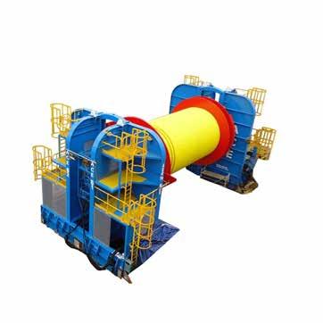
Reel Drive System
Specifications 225Te 500Te Overall dimensions 5880mm L x 2252mm W x 7410mm H8985mm L x 3760mm W x 7560mm H Maximum capacity 225Te SWL (60:40 split) 500Te SWL Maximum reel diameter 7000mm (base frame packers can be supplied to accomodate larger drum sizes) 12800mm Gross weight 30,000kg 55,000kg (per tower) Maximum operating pressure250bar 250bar
Applications
Lifting
Rigging
Mooring
Pulling
Tagging
Features
Suitable for wire rope up to 152mm diameter
Suitable for use in safe area, zone 1 and zone 2
Rollers, Sheaves, Fairleads and Snatchblocks
Standard and bespoke options for guiding wire as required for the application.
Types available include; fixed change of direction sheave, over boarding sheave, arch sheave, horizontal sheave, equalising sheave, swivel head fairlead, roller box fairlead, snatchblocks.
Sheaves Specifications examples
Equalising
Horizontal
550Te @ 180°
3935mm L x 2366mm W x 608mm H
114mm
8000kg
Overboard
300Te @ 180°
2347mm L x 2300mm W x 880mm H
127mm
7750kg
20Te @ 90°
625m L x 225mm W x 660mm H
22-28mm 240kg Safe area and zone 2
Working load limit
Overall dimensions
Wire rope size
Maximum g ross weight
Operational area
Snatchblocks Specifications examples
35 Tonne
35Te @ 180°
2144mm H x 1150mm W x 343mm H
36mm
950kg
27.5 Tonne
27.5Te @ 180°
1442.5mm L x 625mm W x 275mm H
38-42mm 461kg
12.5 Tonne
25Te head load
370mm L x 160mm W x 960mm H
28mm
120kg
Working load limit
Overall dimensions
Wire rope size
Maximum g ross weight
Further assets and wire rope sizes are available. Scan the QR code for more information.
Applications
Wire rope
Synthetic rope
Features
Real-time data
Display unit
Wireless
Suitable for operation in safe areas
Various data logging systems available
Units available for safe areas, zone 1 and zone 2
Running Line Monitor
From 20Te to 250Te
To measure the length, speed and tension of wire paid on or off a winch.
Running Line Monitor
Specifications
250 Tonne
1650mm x 278mm W x 572mm H
150 Tonne
250Te
650kg
800kg
Safe area
1650mm L x 460mm W x 600mm H
60 Tonne
150Te
600kg
750kg
Safe area
986mm L x 324mm W x 358mm H
50 Tonne
60Te
986mm L x 324mm W x 358mm H
150kg
300kg
Safe area
20 Tonne
50Te
150kg
300kg
Safe area
745mm L x 215mm W x 265mm H
20Te
70kg
250kg
Safe areas and zone 1
Overall dimensions
Working load limit
RLM weight
Shipping weight
Operational area
Applications
Wire
Rope
Cable
Umbilical
Hoses
Features
Available as hydraulic and air driven units
Smaller units are supplemented with external HPU’s, electric or diesel, 50Te and above assets have integrated power systems Over or under spooling
Spooling Winch
10Te to 400Te
Designed to facilitate the installation or removal of wire, rope, cables, umbilical and hoses from winches or storage reels under constant back tension. Diesel, electric or pneumatically driven.
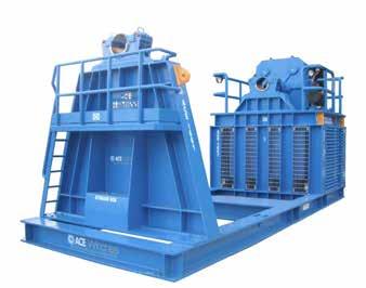
Spooling Winch Specifications
250Te
8155mm L x 3000mm W x 3810mm H
5000mm diameter x 4500mm wide
100 Tonne
8430mm L x 2500mm W x 3600mm H
24,700kg
Safe area only
50 Tonne
6121mm L x 2507mm W x 2705mm H
4500mm diameter x 3900mm
25,000kg
Safe area only
10 Tonne
3512mm diameter x 3534mm wide
9400kg
Safe area only
1540mm L x 3635mm W x 1925mm H
2200mm diameter x 1500mm wide
1700kg
Zone 2 area
Overall dimensions
Maximum reel dimensions
Gross weight
Operational area
Applications
Mooring systems
Pull ahead systems
Fibre rope winching applications
Pipelay and trenching
Offshore and subsea
construction support
Salvage and decommissioning
Features
Hydraulic drive system
Double drum
Synthetic Rope Traction Winch
Standard and bespoke traction winches
Designed to transfer synthetic rope under a high constant upstream tension and transfer the downstream rope to or from a spooling winch under a low tension.
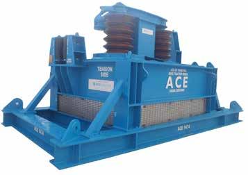
Rope Traction Winch
Specifications
80Te
Overall dimensions
6995mm L x 3615mm W x 3385mm H
Maximum synthetic rope diameter170mm
Gross weight 35,000kg
Maximum operating pressure 210bar
Speak to a member of the ACE Winches team for information on synthetic rope diameters
Applications
Wire change outs on large cranes and winches
Pull ahead systems
Pipe lay and trenching operations
Offshore and subsea construction support
Features
Hydraulically driven
Traction Capstan Spooling Winch 10Te to 60Te back tension capabilities
Designed to facilitate the installation or removal of wire, rope or umbilicals from winches to storage reels under constant back tension.
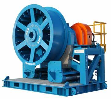
Traction Capstan Spooling Winch
60Te
Specifications Overall
Maximum
Maximum gross weight
Maximum operating pressure 250bar
dimensions 5340mm L x 2935mm W x 3900mm H
150mm
wire diameter
32,000kg
Applications
Hydraulically powered equipment
Features
Open loop axial piston pump
Inline hydraulic air blast cooler
Housed within a fully fabricated framework
Emergency stop button and guards fitted
45kW Diesel Hydraulic Power Unit (HPU)
Suitable for operation in safe areas
Designed to provide power to a range of hydraulically controlled equipment.
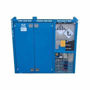
45kW Diesel HPU
Specifications
Overall
Maximum
Maximum
Maximum
Engine
Engine
L x 1050mm W x 1680mm H
@ 2300rpm
@ 2300rpm
2455mm
dimensions
2750kg
gross weight
oil flow 184lpm
main system operating pressure 320bar
start system 12V
power output 45kW
Fuel resevoir capacity 91
litres
Applications
Hydraulically powered equipment
Features
Open loop variable displacement pump
Inline hydraulic air blast cooler
Housed within a fully fabricated framework
Emergency shutdown systems
45kW Electric Hydraulic Power Unit (HPU)
Suitable for operation in zone 1
Designed to provide power to a range of hydraulically controlled equipment.
45kW Electric HPU
Specifications
Overall dimensions 2000mm L x 1205mm W x 1900mm H
Maximum gross weight 3000kg
Maximum oil flow 142lpm @ 60Hz
Maximum main system operating pressure 320bar
Electric motor power output 45kW @ 50Hz 45kW @ 60Hz
Starter type Star delta fitted with overload protection c/w 110V controls
Applications
Hydraulically powered equipment
Features
Closed loop piston pump
Inline hydraulic air blast cooler
Housed within a fully fabricated framework
Emergency stop button and guards fitted
200kW Diesel Hydraulic Power Unit (HPU)
Suitable for operation in safe areas
Designed to provide power to a range of hydraulically controlled equipment.
200kW Diesel HPU
Specifications
Overall dimensions 3500mm L x 2025mm W x 2220mm H Maximum gross weight 6000kg Maximum oil flow 500lpm @ 2200rpm Maximum main system operating pressure 350bar Engine start system 24V Electric Engine power output 235kW Fuel resevoir capacity 300 litres Diesel exhaust fluid reservoir capacity 48 litres
Applications
Hydraulically powered equipment
Features
Closed loop variable displacement, axial piston hydraulic pump
Water cooling, sea or fresh water
Housed within a fabricated steel container
Emergency shutdown systems
400kW Electric Hydraulic Power Unit (HPU)
Suitable for operation in safe area
Designed to provide power to a range of hydraulically controlled equipment.
400kW Electric HPU
Specification
Overall dimensions 4580mm L x 2565mm W x 2660mm H
Maximum gross weight 12,250kg
Maximum oil flow 720lpm @ 60Hz
Maximum main system operating
pressure
350 bar
Electric motor power output 400kW @ 60Hz
Starter type Soft start
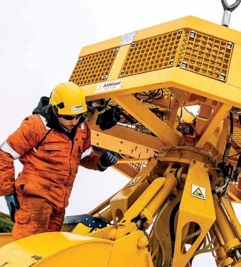
For details on our full equipment fleet, visit ashtead-technology.com
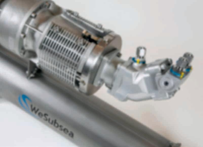
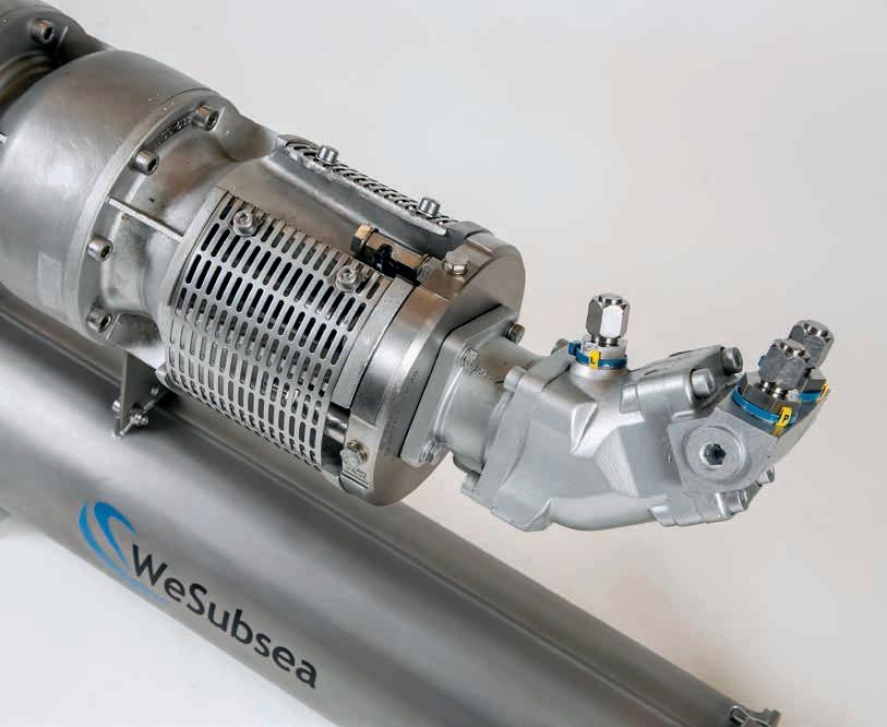
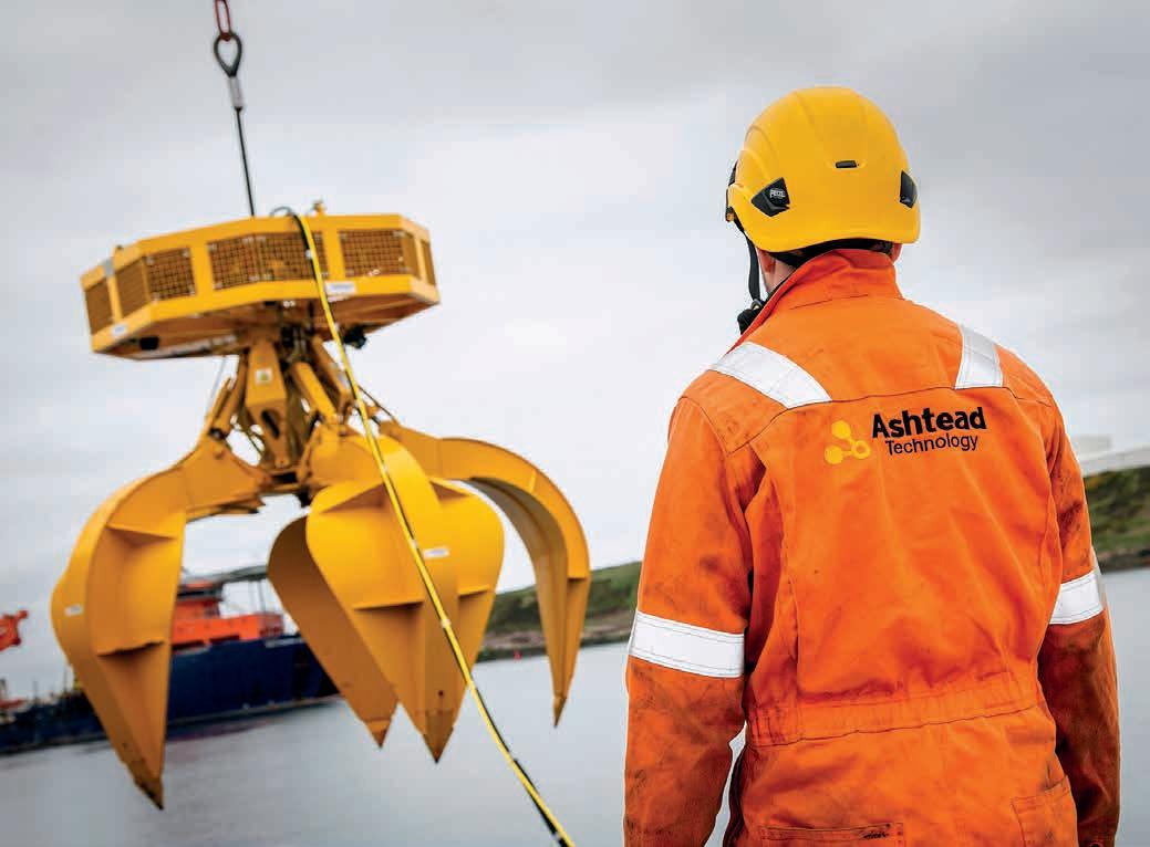
ashtead-technology.com
