17 minute read
Technical

TPMS SERVICE
Gaining a better understanding on diagnosing
By Edwin Hazzard It’s hard to believe that tire pressure monitoring systems (TPMS) have been included in passenger vehicles for a little over 30 years. TPMS started with the European vehicle car lines. The first passenger vehicle to adopt a TPMS was the Porsche 959 in 1986, using a hollow spoke wheel system developed I by PSK. In 1996 Renault used the Michelin PAX system for the Scenic and in 1999 the PSA Peugeot Citroën decided to adopt TPMS as a standard feature on the Peugeot 607. The following year (2000), Renault launched the Laguna II, the first high volume mid-size passenger vehicle in the world to be equipped with TPMS as a standard feature. In the United States, TPMS was introduced by General Motors for the 1991 model year for the Corvette in conjunction with Goodyear run-flat tires. The system uses sensors in the wheels and a driver display which can show tire pressure at any wheel, plus warnings for both high and low pressure. It has been standard on Corvettes ever since. But what led to the industry-wide incorporation of the
COURTESY AUTEL
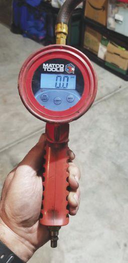
Figure 1: Step one in profitable tire pressure monitoring system service is making sure the tools you are using are top quality, including a TPMS scan tool and tire pressure gauge.
TPMS and why? Vehicle safety is the main reason.
Some of you might remember the Firestone recall back in the late 1990s, which was linked to more than 100 deaths from rollovers following tire tread separation.
This pushed the United States Congress to legislate the Transportation Recall Enhancement, Accountability and Documentation (TREAD) Act. The act mandated the use of a suitable TPMS technology in all light motor vehicles (under 10,000 pounds), to help alert drivers of under-inflation events. This act affects all light motor vehicles sold after Sept. 1, 2007. The first phasein started in October 2005 at
COURTESY OF SOUTHEAST MOBILE TECH
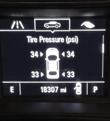
Figure 2: Here’s an image of a tire psi display, this one from a 2017 Chevrolet.
20%, and reached 100% for models produced after September 2007.
In the United States, as of 2008 and the European Union, as of Nov. 1, 2012, all new passenger car models released had to be equipped with a TPMS. From Nov. 1, 2014, all new passenger cars sold in the European Union had to be equipped with a TPMS. I find it quite ironic that the Europeans started the TPMS revolution but they were the last to make it mandatory on their vehicles.
Since tire pressure monitoring systems have been in our service bays now for more than a few years, let’s take a look at some of the service procedures and tools that are needed to service these systems.
In addition to having the latest diagnostic information, tools needed to service these systems today include a competent, high quality scan tool, a reset tool, and an accurate tire pressure gauge (see Figure 1). Some tire pressure gauges can be off as much as five psi or more. Adjusting the tire pressure with an inaccurate gauge will throw off your diagnostic procedure from the start.
It’s very important to test your psi gauge for accuracy and get it repaired or replaced if needed. Don’t rely on the instrument panel display to check the pressures. Sometimes the display will not update quickly enough (see Figure 2).
Another tool that is a must have is the scan tool. Using a low-end tool will not only make your troubleshooting task more difficult, but the tool just might not give you the necessary options that you need to perform the correct task.
For example, the scan tool that you are using might not have the capability to correctly identify the sensor, let alone allow you to input the 10
correct ID for that sensor. Some scan tools will require the use of a separate tool to be used in conjunction with the scan tool.
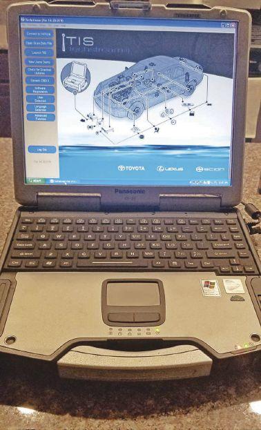
An example of this could be the Toyota Techstream. The Techstream is the OEM factory scan tool that is used in the car dealerships (see Figure 3).
Sometimes you will need a separate tool to retrieve the sensor ID and input that ID into the Techstream to properly register that sensor. Using your service information system and doing a little research on how your particular system works will go a long way in understanding this procedure.
Another factor to consider while repairing a TPMS system is the quality of parts you are using. Make sure to invest in high-quality aftermarket sensors now on the market. Do your homework and find which is best for the vehicles you service.
Direct vs. indirect TPMS On a TPMS system, there are a few components that are used to monitor and help make the system operate correctly. Besides the sensors located in the wheels, these systems have to be monitored by a control module. Sometimes there is more than one controller on the vehicle. The
There are two types of tire pressure monitoring systems — direct and indirect.
sensors report their information to the controller through a wireless radio frequency.
But before we get into the different types of frequencies, let’s look at the two types of TPMS systems. There are indirect type and direct type systems.
The indirect type TPMS does not use physical pressure sensors but measure air pressures by monitoring individual wheel rotational speeds
COURTESY OF SOUTHEAST MOBILE TECH
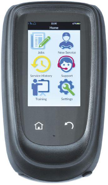
Figure 3: Here’s a Toyota scan tool for a TPMS system.
and other signals available outside of the tire itself. First generation indirect tire pressure monitoring systems are based on the principle that an under-inflated tire has a slightly smaller diameter and a higher angular velocity than a correctly inflated tire. These differences are measurable through the wheel speed sensors of ABS/ESC systems.
Remember I stated the use of multiple controllers? Second generation TPMS can also detect simultaneous under-inflation in up to all four tires using spectrum analysis of individual wheels, which can be realized in software using advanced signal processing techniques. TPMS cannot measure or display absolute pressure values, as they are relative by nature and have to be reset by the driver once the tires are checked and all pressures adjusted correctly.
The reset is normally done either by a physical button or in a menu of the on-board computer or even a scan tool. The reset procedures can be an inconvenience at times. The reset procedure, 12
Figure 4: The Bartec Tech1000 works with all OE TPMS sensors and is easy to operate.
followed by an automatic learning phase of typically 20 to 60 minutes of driving under which the TPMS learns and stores the reference parameters before it becomes fully active, cancels out many, but not all of these. This is not the procedure that makes a flat-rate technician happy.
The other system type is the direct type system. Direct tire pressure monitoring systems employ a pressure sensor on each wheel. The sensors physically measure the tire pressure in each tire and report it to the vehicle’s instrument cluster or a corresponding monitor.
Some units also measure and alert temperatures of the tire as well. These systems can identify under-inflation in any combination, be it one tire or all, simultaneously. Although the systems vary in transmitting options, many TPMS products, both OEM and aftermarket, can display real time tire pressures at each location monitored, whether the vehicle is moving or parked.
There are many different solutions, but all of them have to face the problems of exposure to
hostile environments. The majority are powered by batteries, which limit their useful life. Some of the components of a direct TPMS sensor system consist of the following main functional components: the battery, housing, an analog-digital converter microcontroller, a system controller, an oscillator, radio frequency transmitter, a low frequency receiver, and a voltage regulator which controls battery management.
It sounds more complex and sophisticated than it really is.
Again, understanding the system that you are working on will go a long way in aiding your diagnosis. Some of the maintenance issues you will encounter are valve stem corrosion, battery life of the sensor and tire sealants.
If you live in the Rust Belt area you might see the valve stems having a lot of corrosion due to the treatment they use on the roads along with the incompatibility of the two different metals used between the wheel and the sensor stem.
The battery life will deteriorate over time and the use of improper tire sealant or an excessive amount of sealant can affect sensor operation. Be aware that different manufacturers have different opinions on the use of tire sealant.
Some of the other components used in tire pressure monitoring systems are the monitoring devices that are used to control and track each sensor’s operation.
For example, a 2017 Chevrolet Cruze uses a body control module (BCM), driver information center (DIC), the instrument cluster and a remote control door lock receiver (RCDLR) module to monitor the radio frequency transmitter signal from the sensors in the wheels.
Diagnosing these systems requires an information system that shows not only electrical wiring diagrams but a communication data diagram as well.
Let’s take a look at a TPMS problem that has cropped up on a 2012 Ford F-150 (see Figure 5).
The TPMS light was illuminated. The customer stopped at a repair shop to have it diagnosed and they came up with a code DTC B124D-02. The description for this code is as follows.... If there is a fault with 1, 2 or 3 of the Tire Pressure Monitoring System (TPMS) sensors, DTC B124D-02 sets.
IS THE ONLY TPMS MANUFACTURER TO OFFER A COMPLETE SOLUTION
HIGH QUALITY SENSORS POWERFUL SCAN TOOLS

ALUMINUM OR RUBBER VALVE STEMS AVAILABLE
1-SENSOR
• 1-SKU Limited Inventory • Dual Frequency 315MHz + 433MHz • 99% Vehicle Coverage • Interchangeable Valve Stems
TS508KMV-1
• Read/Relearn All Known Sensors • 4 MX-Sensor Programming Methods • FREE Software Updates for Life of Tool • Exclusive TPMS Status Screen
CONTACT YOUR AUTEL DISTRIBUTOR FOR MORE TPMS KIT OPTIONS

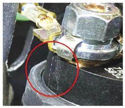
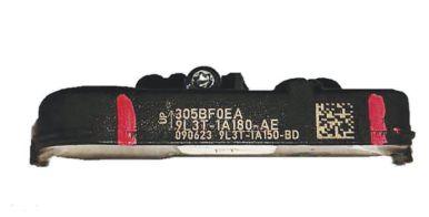
Figure 6: Image of a 2012 Ford F-150 with the wrong sensor.
COURTESY OF MITCHELL PRODEMAND
The TPMS warning indicator flashes for 70 seconds and then remains on continuously when the ignition switch is turned to the ON position and the message center displays TIRE PRESSURE SENSOR FAULT.
The shop narrowed the fault down to a left front tire pressure sensor issue. Usually when this occurs it’s a pretty straight-forward repair. Replace the sensor, learn the system and send it down the road. The shop replaced the sensor and found the problem was still there. Thinking that the new sensor could be faulty, they replaced the sensor a second time.
After installation of the second sensor, the shop decided to call me in for a look. I ran a diagnostic on the truck and sure enough, the DTC was pointing to a left front tire sensor fault. I was 14
Figure 5: A 2012 Ford F-150 pickup with a problem.
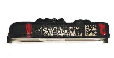
Figure 7: Image of a 2012 Ford F-150 with the correct sensor.
a little skeptical about this, so I told the technician to demount the tire so that I could get a little closer look at the sensor. I was looking for any signs of damage during the install or maybe the wrong type of sensor or maybe even an aftermarket sensor of low quality.
I didn’t find any damage during installation and the sensor was in fact an OEM type sensor. This one had me scratching my head a little as I didn’t physically see anything wrong.
When I start any diagnosis on any type of vehicle, the first thing I do is to take a few minutes and read up on the system I’m working on. That entails opening up the service information system and getting familiar with the players involved and what they are expected to do.
The other thing I do is perform a bulletin
COURTESY OF CONTINENTAL CORP.

Here Continental Corp.’s Tire Industry Association (TIA) and National Institute for Automotive Service Excellence (ASE) Certified Training Specialist Sean Lannoo conducts a relearn.
search and see if quite possibly there is a service bulletin on the problem that I am experiencing. I came across a service bulletin that talked about TPMS sensor identification, specifically choosing the correct sensor for the correct vehicle.
Now remember, the shop replaced the TPMS sensor two times and obtained those sensors from the local Ford dealer.
As I was reading the bulletin, I came across the sensors that pertained to this vehicle. This vehicle lists two possible sensors that can be used for this truck, but each sensor was for two different model years.
Looking at the sensor ID markings it had a marking of 9L3T which is a first-generation valve-mounted sensor. This sensor is not a valid sensor for any 2012 and later model.
The bulletin stated that this truck should have had a CM5T, which is a second-generation valve-mounted sensor. This sensor is a valid sensor and used for model year 2012 and 2013 vehicles only (see Figures 6 and 7).
I told the shop what I found, and they obtained the correct sensor, installed it to the wheel and were finally able to extinguish the TPMS light. There were two issues here.
The first was not getting the correct part from the dealer. That not only happened once but it happened twice! The second issue: Had the shop performed a bulletin search they probably would have caught this problem before everybody got in too deep.
This was a good lesson learned by all who were involved, in that doing a little research on a problem can go a long way.
TPMS vehicles are not quite as complex a system as some of the systems you come across on today’s newer vehicles. Proper understanding of the system, and knowing what players are involved will get the vehicle up and running in no time. It will keep your customer’s pressure in check — both with their tires and their blood pressure. ■
Edwin Hazzard owns South East Mobile Tech in Charleston, S.C., which is a mobile diagnostic and programming service providing technical service to many automotive and body repair shops. He has 37 years’ experience in the automotive industry. He currently is an automotive trainer, a board member of TST (Technician Service Training), a member of the MDG (Mobile Diagnostic Group), a member of the Professional Tool and Equipment advisory board for Pten magazine, a committee member of Nastaf, and is a beta tester for multiple tool makers.


FORD STARVING MUSTANG

Some 2018-2019 Ford Mustangs built on or before Oct. 17, 2018, with a 2.3L EcoBoost engine and operating in altitudes of 3500 feet above sea level and higher may exhibit an illuminated MIL with only DTC P0069 stored in the PCM.
Using the appropriate diagnostic tool, retrieve DTCs. If the only DTC stored is P0068, reprogram the PCM using the latest software version. This will recalibrate for the thinner air conditions found at high altitudes.
ALL TSBS COURTESY OF MITCHELL I, WWW.MITCHELL1.COM
JAGUAR MODULE UPDATE This bulletin applies to 2018 Jaguar XJ Supercharged, E-Pace/X540, FPace/X761, F-Type/X152, I-Pace/ X590, XE/X760, XF/X260 and XJ/ X351 vehicles. When attempting to update or replace the information master control module (IMC) or the infotainment slave control module (ISC) using Pathfinder v225, it may be noticed that the application aborts, with a displayed error message stating “Updating IMC: Updating of ECU IMC X351_2016_00_V7 is not possible because required flash files (LX73-19C204-AA/LX73-19C204-ADA) were not found; or “Updating of ECU IMC X351_2016_00_ V7 is not possible because required flash files (LX73-11E013-AA/LX73-11E013-ADA) were not found.”
There are files required for the IMC or ISC update process that have not been included in the v225 release of Pathfinder. A work-around will load a software file to the Jaguar Land Rover approved diagnostic equipment using the manual patch update process. This manual patch will stay on the JLRapproved diagnostic equipment. • Restart the JLR-approved diagnostic equipment. • Select “Manual Patch” icon on the application launcher screen. Make sure that both symptom driven diagnostics (SDD) and Pathfinder are closed before opening the manual patch downloader. • A pop-up will be displayed for manual patch downloader. • Enter “MP_PF_L0054” in the patch name field. • Select “Start.” • The manual patch downloader will then download the manual patch. • When the patch download has completed, a message will be displayed asking the user to confirm that the application can run the manual patch. Select “Yes.” • When complete, the following message will be displayed: “Successfully downloaded and started manual patch. Please make sure that the patch has installed successfully.” This message will end after 10 seconds. • Start a new diagnostic session. • Select “ECU Diagnostics.” • Select “Infotainment Master Control Module (IMC).” • Select “Update” or “Replace” ECU. • Follow all on-screen instructions to complete the task. 16

BMW BMW LOUSY IDLE This bulletin applies to 2018 BMW 340I GT xDrive vehicles. The vehicle may run rough or hesitate when accelerating from a stationary position and fault code FC 21A02D (combustion control: valve lift correction when at idle) may be stored in DME fault memory. The cause may be a software error in the DME (digital motor electronics). The correction involves updating the vehicle software using ISTA 4. • If other faults are stored, diagnose and repair before the update. Do not replace any parts to specifi cally address DME FC 21A02D. • Program the vehicle using ISTA 4.10.20 or higher to integration level 18-03-520 or higher.

DODGE RAM FUEL INJECTOR SHORT This bulletin applies to 2017 Dodge Ram 3500, 4500/5500 trucks equipped with a 6.7L Cummins diesel engine and built on or after Nov. 23, 2016, and on or before March 17, 2017. The bulletin involves inspection testing and replacement of the fuel injectors.
Customers may experience a MIL on. The technician may find one of the following codes set: P0201....fuel injector 1 circuit/open P0202....fuel injector 2 circuit/open P0203....fuel injector 3 circuit/open P0204....fuel injector 4 circuit/open P0205....fuel injector 5 circuit/open P0206....fuel injector 6 circuit/open
Scan for DTCs. If DTCs appear other than those listed here, record and repair as needed before continuing. Note: Do not remove the injector harness or terminal nuts after removing the cylinder head cover. • Remove the cylinder head cover. When servicing Dodge Ram 3500, 4500/5500 diesel trucks, inspect the injector terminal posts for signs of metal shavings around the terminal nuts. • Inspect the area around the injector terminal posts for the presence of any metal shavings around the terminal nuts. • Using a multimeter set to the continuity setting, check all six injectors for a short to ground by placing one lead on a metal grounded contact such as the injector mounting clamp or rocker pedestal, and the other lead to each injector terminal post. • Remove the terminals of the injector(s) that have a short to ground and check both terminals on the injector(s) for short to ground. • If a short is present, replace the shorted fuel injector(s) and fuel injector supply tube(s). • Check for any metal shavings that might have been created during re-torquing the injector terminal nuts. Remove any shavings. • Re-confirm with a multimeter that the new injector(s) does not have a short to ground condition. • Install the cylinder head cover. • Clear all DTCs that may have set in any module. • Perform the powertrain verification test. Refer to the service procedures available in DealerCONNECT> TechCONNECT under Service Info>28 – DTC-Based Diagnostics/Module, Powertrain Control (PCM). ■