21 minute read
Understanding modern day ignition systems

Tips for diagnosing popular systems
TThere have been many enhancements on today’s modern day ignition systems so as to make the modern day technician’s job easier of investigating the popular misfire code or a misfire symptom without a misfire code.
Normally with a misfire code or a misfire symptom, most technicians initially suspect an ignition problem such as a bad coil, a faulty secondary lead or a bad spark plug. As we all know, you cannot undermine what you feel through the seat of your pants when doing a test drive and experience what you initially think is a misfire. By Bill Fulton
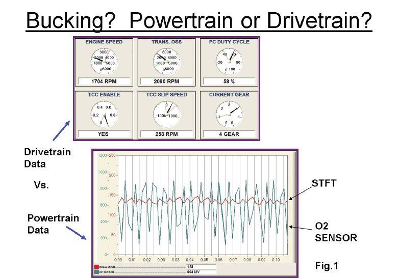
Always take along a scan tool and record the data when the symptom occurs. A GM vehicle we serviced recently exhibited the exact symptoms of a jerk and buck that we feel during a misfire event. There was no MIL and no codes.
Note Figure 1. The scan tool is set up to do a snapshot record. We are using the graphing mode of the scan tool as we recall the 10 second record. Notice the bottom graph. The 02 sensor values are being graphed out as well as the integrator values now known as short term fuel trim. If an ignition-related misfire had occurred we would have seen the O2 voltage go momentarily
Figure 2: Chrysler COP (coil on plug) system. A COP wand is used on top of the coil to look at the secondary. By back probing the coil negative terminal we view the primary side of the coil.
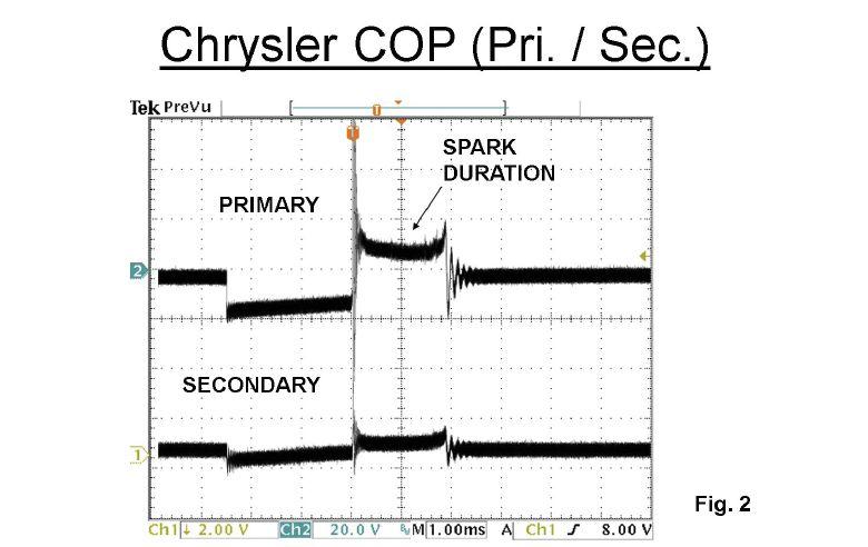
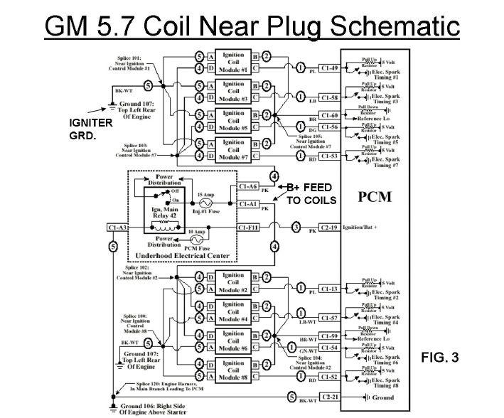

Figure 4: A main ignition repay provides B+ to all coils. This valuable parameter is available on the scan tool and should indicate good supply voltage to the coils.
low from unburned O2 molecules and the result would be that the PCM would momentarily add fuel by increasing the integrator numbers.
As you can see in our scan tool record this simply did not happen. The integrators numbers stayed at 128 which is 0% short term fuel correction. This tells us the symptom was not power train related. In our earlier articles we stated that an ignition-related misfire from loss of spark from a single cylinder misfire will only momentarily create minor single digit fuel trim corrections when the O2 sensor senses unburned oxygen. A lean density misfire, however, will create double digit fuel trim corrections to the positive side. A rich density misfire will create double digit negative fuel trim corrections.
Another test drive was in order. This time we would record drive train transmission data when the symptom occurred. Note the top transmission data in Figure 1. We have converted the data into an analog gauge format. Notice that we are in fourth gear and the torque converter clutch has been commanded on. Now notice the parameter called TCC slippage.
The red needle shows maximum slippage while the green needle indicates minimum slippage. The black needle is the current slippage. 22
During the symptom the black needle fluctuated between the min/max values.
While we initially thought that the symptom was misfire related, it turned out to be from the transmission due to a slipping torque converter. Using scan data can be very helpful.
In the event where a single cylinder misfire is occurring and a single cylinder misfire code is set, take a few minutes and analyze the freeze frame values. When you see double digit positive fuel trim values the misfire is a lean density misfire.
There are two things to keep in mind here. Number 1, the PCM must be in closed loop to get the advantage of using fuel trim values. Number 2, modern day PCMs will force the engine back into open loop and disable the injector simply to save the catalytic converter.
Don’t always take the freeze frame data as gospel. Clear the code and set up the scan tool for a record function. Record the data when you first feel the misfire before the PCM forces the engine out of closed loop. Minor single digit fuel trim corrections point to a loss of spark from a single cylinder misfire. Double digit fuel trim corrections either positive or negative point to an air fuel ratio related misfire.
Figure 5: A Chrysler system. The scan tool parameter indicates the ionization value (important spark duration period). The PCM monitors how many times it took the magnetic field to collapse.
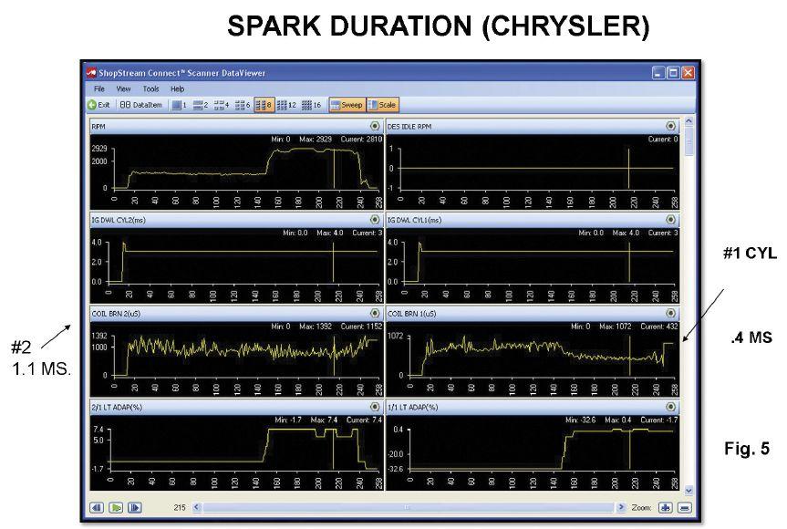
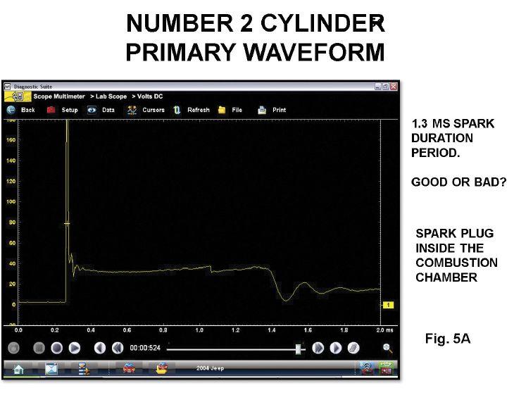

Figure 6: Notice the spark plug gap erosion and carbon impregnation on the Chrysler number 2 spark plug.
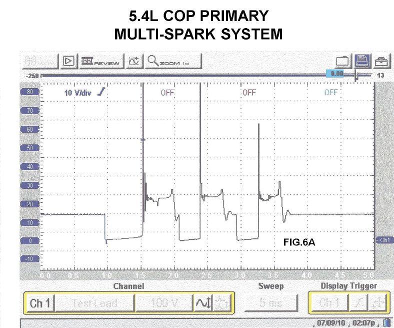
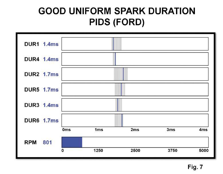
Figure 7: A Ford COP showing uniform spark duration periods.
Most all late model ignition systems are now using coil-on-plug (COP) type coils or coil near plug as found on the GM Vortec engines. There is also a system called integrated direct ignition (IDI) as found on the GM Ecotech engines. The coils are buried under the valve cover so access to the coils would not be possible without removing the valve cover. There is a plastic ornament cover on top of the valve cover on some engines that can be removed and by using a COP wand, this will indicate a secondary waveform during cranking if spark is occurring.
Chrysler and Ford systems incorporate the primary coil driver inside the PCM. For you savvy scope users, probing the coil negative primary wire will yield a primary waveform. The diagnostic value here is that a primary waveform yields the same diagnostic information to that of a secondary waveform. See Figure 6A from a Ford multi spark COP system. Ford modern day ignition systems will multi fire the coils below 1,000 rpm. If we add all three spark duration periods it comes to over 1.5 milliseconds. See Figure 2 from a Chrysler COP unit. We are using a COP wand on top of the coil to look at the secondary, and by 26
back-probing the coil negative terminal to view the primary side of the coil.
Did you notice that the spark line durations are identical? Most technicians are aware of the actuator test mode on the Chrysler systems whereas each coil can be commanded to fire individually every 2 seconds during KOEO (key on, engine off).
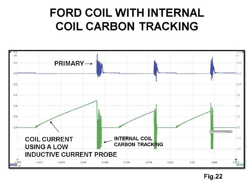
We all have experienced failures on Ford COP units from MY 2005 thru MY 2009, sometimes taking out the PCM driver which is usually caused by internal coil carbon tracking. On the early Ford COP units, a secondary KV wand can be placed on top of the coil to obtain a secondary ignition waveform.
In an October 2018 article in ASP, we covered the diagnostic value of scoping the secondary side of the ignition. Most of the modern COP coils are more heavily potted, which prevents a strong enough magnetic field to be picked up with a COP wand. In addition, most COP coils have the igniter built into the coil, which is controlled by a low voltage low current driver per coil inside the PCM. These type coils have no access to the primary negative side of the coil
Figure 8: A Ford COP showing a short spark duration period on number 3 cylinder.
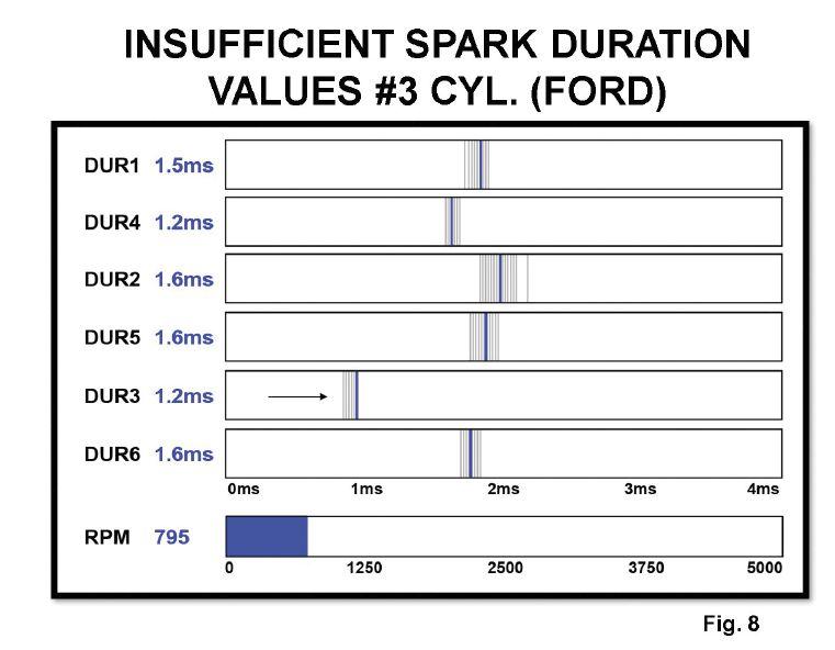
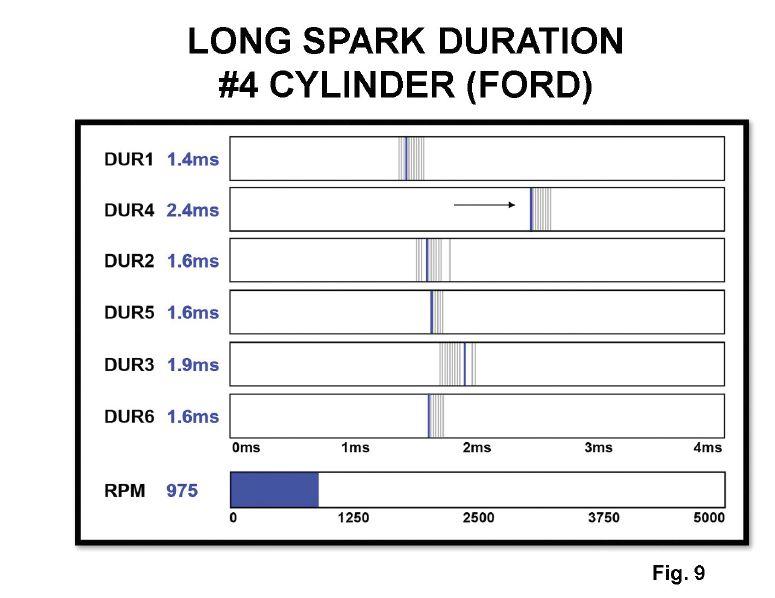
Figure 10: A Ford COP showing insufficient acceleration PID on number 4 cylinder.
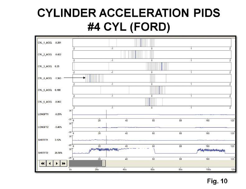
Figure 11: An important parameter on all CAN compliant vehicles is misfires detected from the last 10 drive cycles. This information is available on the global side of the scan tool by selecting Mode 6 test results.
28
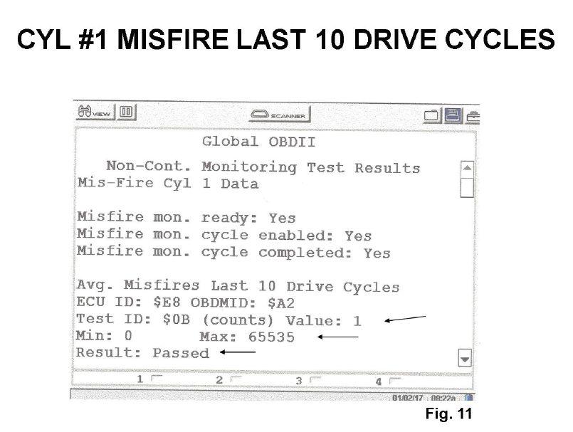
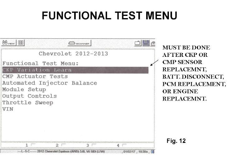
Figure 12: On GM vehicles, a scan tool function allows us to cause the PCM to relearn good crank angle values.
since the igniter is built into the COP unit. Later on in this article we will discuss the diagnostic value of using a low inductive current probe in order to check for good coil saturation values and pinpointing the problem of internal coil carbon tracking.
Spark plugs Let’s look at an ignition schematic from a late mode GM Vortec engine (see Figure 3 on page 21). These coils are connected to the spark plug by an 8-inch secondary lead. Access to secondary is easy by clamping the KV probe to the plug wire. A 1 millisecond time base at a 1KV per division should give you a good waveform.
Remember, you must use the invert function and peak detect mode of the scope, since secondary is fired negatively. The coils will easily maintain a 2 millisecond spark duration period during park idle no load conditions. GM has used three different vendors to supply these coils including Delphi, Denso and Melco. None of these coils are interchangeable.
In addition, the short secondary leads vary greatly in resistance values per coil and engine. Make certain to use the proper secondary lead per application.
Looking at our schematic in Figure 3, note 30
that a main ignition relay provides B+ to all the coils. This valuable parameter is available on the scan tool and should obviously indicate good supply voltage to the coils (see Figure 4 on page 22). You will also note that all of the coil’s igniters receive their ground on the left back side of the cylinder block. These coils can pull up to 10 amps on a cold startup so the B+ and igniter grounds may need to be checked.
I have seen many misfire codes from vehicles with over 100K miles on the clock with the original spark plugs. Double tip platinum plugs and the iridium plugs have greatly reduced the gap erosion problem.
Another common problem on spark plugs is known as carbon impregnation. Carbon is a terrible conductor of current flow which raises the secondary KV demand which can easily cause a COP failure.
Most good technicians will not address a misfire code with a high mileage engine with the original spark plugs. That is of course making sure the mechanical integrity of the engine has first been verified and fuel trim values do not point to an air/fuel ratio-related misfire.
On most COP systems except Ford and Chrysler, the coil igniters are forward biased by the PCM. The PCM driver per coil will send a
Figure 13: On Ford systems, when a misfire has been detected, the PCM provides additional information including profile correction.


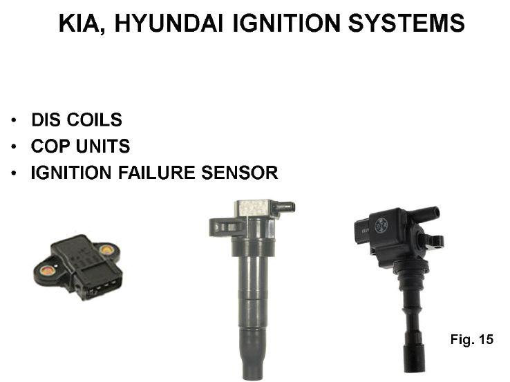
Figure 15: Kia and Hyundai ignition systems feature an igniter built into the coil. A unique feature in the system is an ignition failure sensor. When a coil fires, the failure sensor sends a 12-volt pulse back to the PCM. If the PCM does not see the 12-volt pulse, it will disable the injectors.
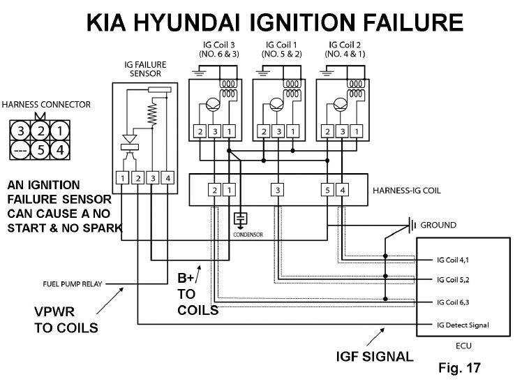
Figure 17: A 4-trace example on a 3.5L Hyundai. Note the 12-volt pulse from the ignition failure sensor and the trigger signal to the coils.

5-volt signal to the igniter. The 5 volts turns the igniter on and begins the coils’ charge process. When the PCM driver shifts this voltage back to 0 volts, the primary current flow is interrupted and the primary magnetic field collapses and is mutually inducted into the secondary windings.
There are 100 more turns of wire on the secondary side which means a 300 voltage value on the primary side of the coil would create 30KV from the secondary side of the coil. For those technicians who use the adjustable spark testers, a ¾ inch air gap comes very close to a 30KV demand.
All COP coils are designed to deliver 30,000 volts. The COP/ IGNITOR units can be biased with a conventional test light.
Refer back to the Figure 3 schematic. Let’s say there is no spark on number 1 coil. We would simply connect our test light alligator clip to the positive battery terminal. While momentarily probing the igniter control wire (purple wire) produces a good spark, we now may have a circuit problem between the PCM or a bad igniter driver inside the PCM. If you refer to the schematic you will see a pink wire from the main ignition relay 34
that powers up all the coils. This wire goes thru a connector on top of the valve cover which is known to intermittently cause loss of B+ to the coils creating an intermittent P0300 code. You would definitely want to perform a wiggle test on this connector.
Since the coils’ primary drivers are inside the PCM on the Chrysler and Ford COP systems, we now have some scan data to look at related to spark duration. Let’s start first with the Chrysler systems (see Figure 5 on page 23). The scan tool parameter indicates the ionization value which we will refer as the important spark duration period. The PCM simply monitors how many times it took the magnetic field to collapse.
Take a look at the scan tool parameter of the number 1 coil at .4 milliseconds. Now look at the number 2 coil’s ionization value of just over 1 millisecond. These values should always be observed but are relative values only and are not the true values.
Let’s use a scope and look at the primary waveform on cylinder number 2 in Figure 5A. Note that the spark line duration period during park idle no load conditions indicate a 1.3 mil-
Figure 18: Toyota systems also feature an integrated ignitor inside each COP (coil on plug).

Figure 19: A dual trace example on a Toyota of secondary and IGT signal. Note the rising edge of the IGT signal lines up with the point of primary turn-on while the falling edge of the IGT signal lines up with the during event.
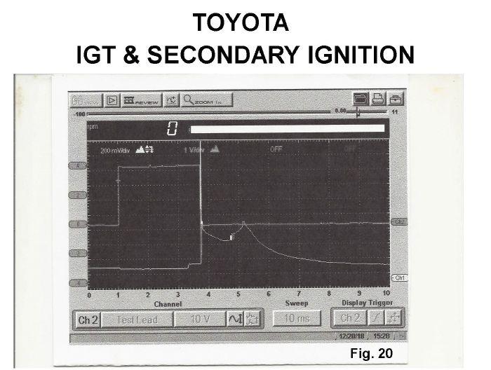
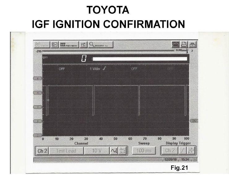
Figure 20: Toyota secondary and IGT signal. When a coil is charged and fired, the IGF signal is pulled low. If the IGF signal fails, the PCM will disable the injectors. A shorted coil will cause loss of IGF and a no-start.
lisecond spark duration period, well short of the minimum 1.5 milliseconds we would like to see.
Notice the spark plug gap erosion and carbon impregnation of the number 2 spark plug in Figure 6 on page 24. This is a common example of why we cannot properly diagnose the cause of a misfire code when dealing with worn out and carbon impregnated spark plugs.
We all know that most car owners do not follow the manufacturer’s recommended spark plug change intervals. I will not take the time to tell you the misfire cases I have diagnosed were the result of worn-out spark plugs or spark plugs that were carbon impregnated long before the manufacturer recommended replacement period.
The Ford COP systems will give you some valuable diagnostics via the scan data as well. The PCM simply monitors the time it took for the magnetic field to collapse. This is what aftermarket technicians refer to as the important spark duration period. Though this is an important parameter to monitor, keep in mind that the values indicated on the scan tool are relative and not the absolute true value. It’s a matter of looking at the odd man out, meaning what cylinder shows a longer or shorter duration compared to other cylinders.
Note Figure 7 (page 26), which shows uniform spark duration periods. And then note Figure 8 (page 27), which shows a short spark duration period on number 3 cylinder. This could be caused by a lean density condition on number 3 cylinder or by a weak coil as well as an open spark plug resistor. Now note Figure 9, which indicates a long spark duration period on number 2 cylinder. This could be caused by low compression or a rich density condition. Keep in mind these are relative values only. If you were to probe the negative side of the coil with a DSO (digital storage oscilloscope) you would see the actual true spark duration periods.
Another parameter from the scan tool of modern Ford systems is known as cylinder acceleration PIDS (on board diagnostic parameter IDs). When a good combustion event occurs, the crank speed (angles) will accelerate. When a misfire occurs, this crank speed slows down. These parameters would be good to monitor during a
misfire that occurs under road load conditions. Note Figure 10 and notice the insufficient acceleration PID on the number 4 cylinder.
Another important parameter available on all CAN-compliant vehicles is known as misfires detected from the last 10 drive cycles (see Figure 11 on page 28). This information is available on the global side of the scan tool by selecting Mode 6 test results. The PCM will only recognize a type A or B misfire with a DTC and a MIL. Type C misfires are basically ignored by the PCM and not the driver, can easily be detected from the Mode 6 test results.
There have been many cases from my experiences whereas the PCM flagged the wrong misfiring cylinder during a misfire event or set a P0300 misfire code with no misfire symptoms occurring. Many manufacturers give us the ability to cause the PCM to relearn good crank angle values. On the GM systems this is simply a scan tool function (see Figure 12, page 30). On the Ford systems whenever a misfire has been detected and the MIL is lit, the PCM will give us some additional data (see Figure 13, page 31).
One of the parameters is profile correction. Yes means that the PCM has learned the crank angle values. No means it has not. To reset the crank profile values you must first clear the Keep Alive Memory. You will need to drive the vehicle by accelerating to 60 mph and then decelerating to 40 mph. You cannot apply the brake and the A/C must be off.
The Chrysler systems have a similar scan tool function for the PCM to relearn good crank angle values (see Figure 14, page 31). These procedures must be done if a crank or cam sensor has been replaced or if the engine has been replaced as well as internal engine parts as well as the PCM.
The Kia and Hyundai ignition systems can be the DIS type systems as found on the 3.5L engine or the COP design found on other engines. Both systems have the igniter built into to the coil. The PCM will forward bias the igniter to charge the coil.
A unique component in the ignition system is called an ignition failure sensor (see Figure 15 on page 32.) Whenever a coil fires the ignition, the failure sensor will send a 12-volt pulse back
CLEAN POWER FOR OPTIMAL REPROGRAMMING
The PL6100 from SOLAR provides an ideal stable power supply mode to maintain vehicle system voltage during reflashing events:
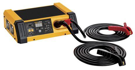
• Continuous power up to 100A (no time limit) • Selectable target voltage from 13.1-14.9V • Minimal voltage ripple (<100mV) • Rapid Load Response Technology • Extra-long 13’ cable reach • Includes charging capability (60/40/10A) • Requires 20A outlet
Charge mode compatible with a wide variety of battery types:

Figure 21: Using a spark tester on a Ford system that creates a 30KV demand. With an amp probe at the B+ feed circuit, note the erratic energy transfer from secondary to primary from internal coil carbon tracking.
to the PCM. If the PCM does not see this 12-volt pulse it will disable the injectors. A failed ignition failure sensor will create a no start and will set P0350 code.
Let’s look at the schematic in Figure 16 on page 32. Notice that the ignition failure sensor contains a resistor. If this resistor burns out we lose B+ to the coils, creating a no-start/no-spark condition, requiring sensor replacement.
Figure 17 on page 34 shows a 4 trace example from a 3.5L Hyundai engine. Notice the 12-volt pulse from the ignition failure sensor to the PCM and the igniter trigger signal from the PCM to the coil/igniter units. As with most igniters they are forward biased by the PCM.
The Toyota ignition systems also use an integrated igniter inside each COP. A Toyota ignition schematic is shown in Figure 18 (page 35). The PCM will forward bias the igniter with a 5 volts signal to turn on coil current and charge the coil. When this voltage shifts to 0 volts the current turns off and the magnetic field collapses, thus inducing a voltage into the secondary coil windings. Notice the current flow values at 7 amps. 38
Figure 19 (page 35) shows a dual trace example of secondary and the IGT signal. Notice that the rising edge of the IGT signal (ignition timing signal) lines up with the point of primary turn on while the falling edge of the IGT signal lines up with the actual firing event.
Figure 20 (page 36) indicates secondary and the IGF signal (IGF provides the PCM with failsafe fuel cut-off if ignition spark is lost). When a coil is charged and fired the IGF signal is pulled low. If the IGF signal fails, the PCM will disable the injectors. A shorted coil will cause the loss of the IGF signal and cause a no start. The secondary waveforms in Figures 19 and 20 were obtained by using a secondary lead between the COP unit and the spark plug. We simply clamped our KV probe around the secondary lead. The IGT and IGF signal were obtained by back probing the connector at the COP unit.
We cannot over-emphasize the diagnostic value from a low inductive amp probe combined with a DSO. Considering some coils are not easily accessible, we simply use an amp probe clamped around the B+ circuit or in some cases
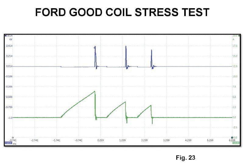
Figure 22: An example of a good stress test on a coil and a clean amperage waveform.
we simply jumper across the fuse that supplies B+ to the coils. There are two diagnostic reasons here. Number 1 is simply checking for spark and number 2 is to check for failed coils that show internal coil carbon tracking.
Notice Figure 21 from a Ford system. We are using a spark tester that creates a 30KV demand. We are probing the coil negative terminal to view the primary side of the ignition system. With an amp probe clamped around the B+ feed circuit to the coil, notice the erratic transfer of energy back from secondary into primary from internal coil carbon tracking. This is a common case that can take out the primary driver inside the PCM.
Figure 22 shows a good stress test on the coil and a clean amperage waveform.
When using an amp probe to check for good coil saturation values, we are checking to ensure the smooth and good transfer of energy from the primary side of the coil to the secondary side of the coil. Keep in mind that there is no diagnostic information from a primary amperage waveform as related to the important spark duration periods and spark line characteristics as seen when viewing a secondary waveform.
We covered in an earlier article the diagnostic value of a secondary ignition waveform. The process needed on the coils (where the igniter is integrated in the coil with no access to the primary negative terminal) when you want to view a primary ignition waveform, is to use a secondary lead between the COP unit and the spark plug and use a secondary KV probe clamped around the secondary leak. These leads and KV probes are available from AES WAVE .com. ■
Bill Fulton is the author of Mitchell 1’s Advanced Engine Performance Diagnostics and Advanced Engine Diagnostics manuals. He is also the author of several lab scope and drivability manuals such as Ford, Toyota, GM, and Chrysler OBD I and OBD II systems, Fuel System Testing, many other training manuals in addition to his own 101 Lab Scope Testing Tips. He is a certified Master Technician with over 30 years of training and R&D experience. He was rated in the top three nationally in Motor Service Magazine’s Top Technical Trainer Award and has instructed for Mitchell 1, Precision Tune, OTC, O’Reilly Auto Parts, BWD, JD Byrider, Snap-on Vetronix and Standard Ignition programs. You may have also seen Fulton in many Lightning Bolt Training videos and DVDs and read his articles in many auto service magazines. He currently owns and operates Ohio Automotive Technology, which is an automotive repair and research development center.


