24 minute read
Targeted advice from automotive parts manufacturers and suppliers

Federated Offers Premium Braking Performance for Today’s Vehicles
Federated Auto Parts has developed an addition to its friction offering with a new co-label line developed and supplied by Wagner Brake. The new product line is a premium offering designed for professionals that was exclusively designed for Federated members and their customers.
The line uses the highest performing formulas specif c to each application and includes System Synergy Technology (SST) which is an OE approach to brake design that ensures the interaction of all brake components to provide the ultimate performance.
Each set of Federated Professional Premium is engineered and designed to match the OE pad in f t, form and function and uses premium formulations and shims for ultimate performance on each application.
The System Synergy Technology focuses on managing the NVH (noise, vibration, and harshness) issues through testing and validation of the various components used in disc pad designs. While many consider a disc brake pad one component it actually consists of many different components including backing plates, shims, hardware, along with friction material, slots and chamfers that all must be designed to work together to deliver ultimate performance.
Working with Wagner Brake experts, Federated has developed a product line that uses OE designs, and improvements in materials and component integration, to deliver superior performance to other aftermarket lines. The Federated Professional Premium line provides superior braking performance, long life and quiet operation for customers who perform premium brake service and have a reputation for using high quality brand name parts.
Federated has a history of working closely with high-quality manufacturers to develop exclusive products designed specif cally for use by quality technicians and professional service providers. The Federated Professional Premium line of disc brakes is designed to take all the mystery out of all the different materials and grades available in the market today by using SST to focus on the best solution for each vehicle.
Federated Professional Premium brake uses an OE approach to the design process that delivers the ultimate in overall performance for the professional service provider and is available exclusively from members and aff liates of Federated Auto Parts.
“We spent countless hours working with Wagner Brake experts in designing this line,” stated Phil Moore, senior vice president for Federated Auto Parts. “Working with Wagner and Federal Mogul made this project easier due to their commitment to quality and their outstanding manufacturing and R&D facility in Smithville, Tenn.” ●
Federated Auto Parts
508 Greenville Ave. Staunton, VA 24401 540-885-8460 www.federatedautoparts.com.
How to Address Steering Noise in GM Crossover Vehicles
Here are procedures for eliminating steering gear squeak noise in certain General Motors crossover vehicles:
To prevent a steering gear squeak noise on 2008-2012 Buick Enclave, 2009-2012 Chevrolet Traverse, 2007-2012 Acadia and 2007-2012 Saturn Outlook crossovers built prior to July 1, 2011, GM recommends that the power steering f uid be changed to DEXRON-VI automatic transmission f uid when a steering gear assembly is replaced for any reason.

The original cause of the squeak noise may be due to insuff cient grease in the pinion shaft seal. The pinion shaft seal to pinion strut interface and lack of lubrication may generate a noise. This noise originates in the gear but may sound like it is coming from the steering column area. The steering gear assembly should not be replaced for this squeak noise condition. For the squeak noise, only the steering gear housing should be replaced, and the power steering system should be ref lled with DEXRON-VI, which offers the permanent correction for the squeak noise.
In addition to the squeak noise correction, the recommendation to convert the power steering f uid to DEXRON-VI is for gear replacements only and not for repairs to other system components, such as the pump, cooler or hoses.
A tag identifying that the vehicle has been converted to DEXRON-VI should be installed on the power steering reservoir f ller neck and secured with the cap.
If the power steering system on these vehicles has the original f uid, the system should be f ushed and ref lled with DEXRONVI. Due to the interface between the pinion shaft seal and the f uid, it is critical to ensure no f uid comes in contact with the new seal. Be sure to thoroughly f ush all old f uid from the system prior to installing the new steering gear assembly or housing.
When changing the f uid, raise the vehicle until the wheels are approximately 24 inches off the ground. Disconnect the power steering f uid reservoir inlet hose from the power steering f uid reservoir and plug the power steering f uid reservoir inlet port. With the key ON and the engine OFF, turn the steering wheel fully to the left and to the right while an assistant maintains the minimum f uid level in the reservoir using DEXRON-VI f uid. Continue until the f uid from the power steering f uid reservoir inlet hose turns red. This may require up to three quarts of DEXRON-VI f uid.
Learn more about ACDelco at www.acdelco.com (1-800-ACDelco) ●

ACDelco World Headquarters
6200 Grand Pointe Dr. Mail code: 484-393-312 Grand Blanc, MI 48439

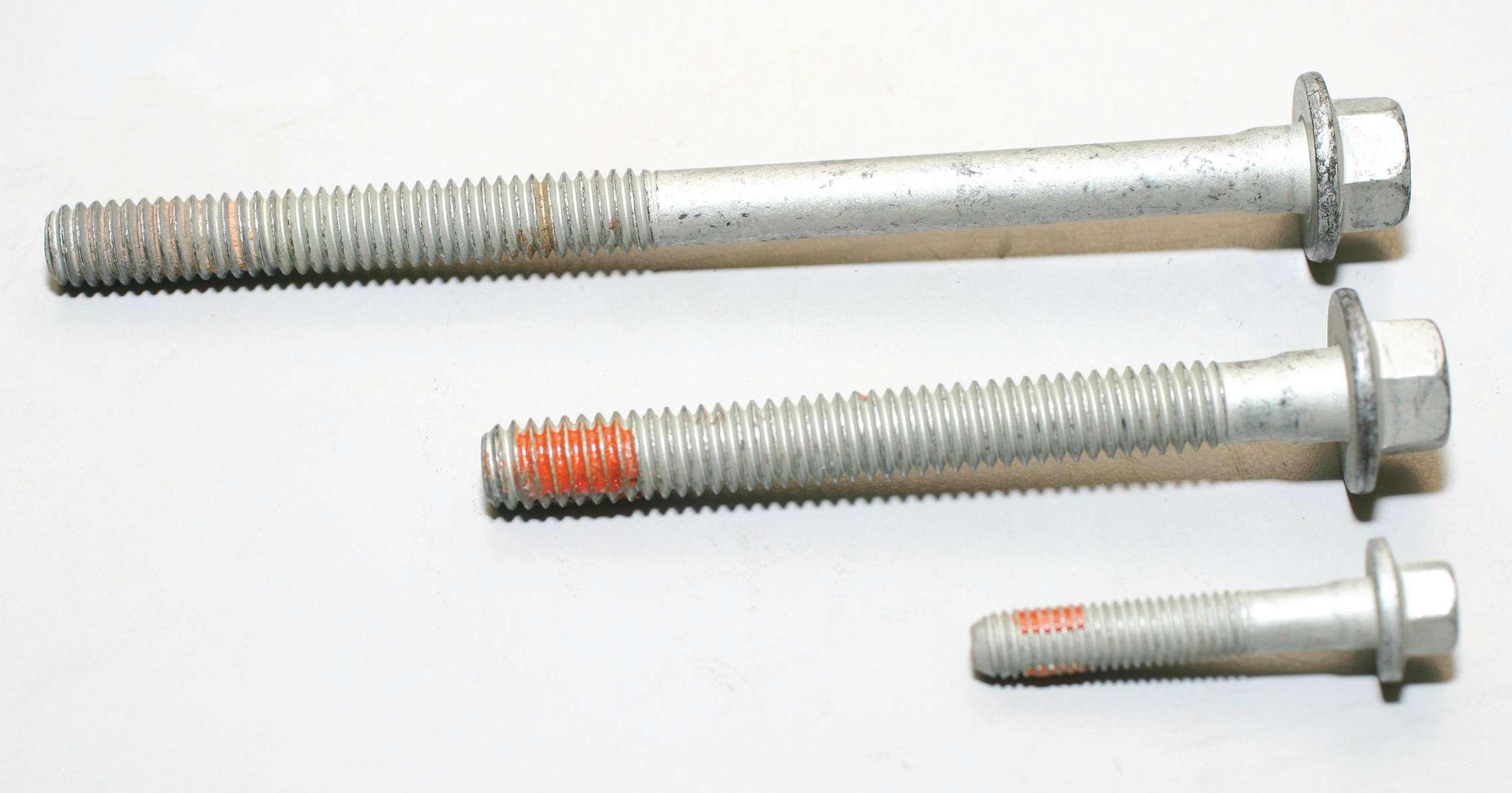
Cleaning the Fuel Tank
One of the main causes for fuel pump failures is contaminated fuel. Visible and invisible contaminants can damage a new fuel pump. Therefore, it is very important to clean and f ush the fuel tank to remove these contaminants when replacing a fuel pump.
Contamination in a vehicle’s fuel tank can occur from a number of causes, such as corrosion, debris and moisture. Moisture is one of the more common contaminants, which can be introduced into the tank from f lling the vehicle and condensation forms on the tank walls from temperature variances. Moisture is the root cause of corrosion, sediment and unseen contaminants such as bacteria or fungus at the bottom of tanks. Dirty caps, tank spouts and funnels can contribute to contamination in the fuel tank as well.
Contaminants will clog the fuel f lter, fuel lines, fuel injectors and the fuel pump itself, preventing the engine from running. If you are replacing a fuel pump, it is imperative that you clean the outside and thoroughly f ush the inside of the fuel tank and ref ll the tank with clean fuel. While you are at it, replace the inline f lter and in-tank strainer and even f ush the fuel lines since those parts will have residual contaminants in them.
STEP 1: Empty fuel from fuel tank
Drain fuel into approved f ltering container or dispose of per local codes or regulations. Consult repair manual for proper procedures.
STEP 3: Clean outside of tank
Remove build up and rust from the top of tank, avoiding contamination of inside the fuel tank.
STEP 4: Remove the lock ring and fuel pump assembly
Consult repair manual for proper procedures.
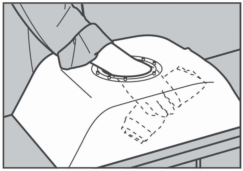
STEP 5: Clean inside of fuel tank
• Swirl remaining fuel in circular motion to gather loose contaminants. • Slowly pour contaminated fuel into approved container and dispose of per local codes or regulations. • Turn over fuel tank and tap to remove remaining contaminants. • Clean inside with mild liquid detergent and water. • Use a lint-free shop towel to wipe the inside of the fuel tank clean. • Empty and dry inside of fuel tank with compressed air. • Inspect fuel tank for rust and physical damage. Repair or replace if signs of either. • Allow the tank to sit for at least one half hour or until completely dry. ●
Airtex Products LP
407 W. Main St. Fairf eld, IL 62837 FREE Tech Line: 800-424-7839 www.AirtexProducts.com www.FuelPumpU.com

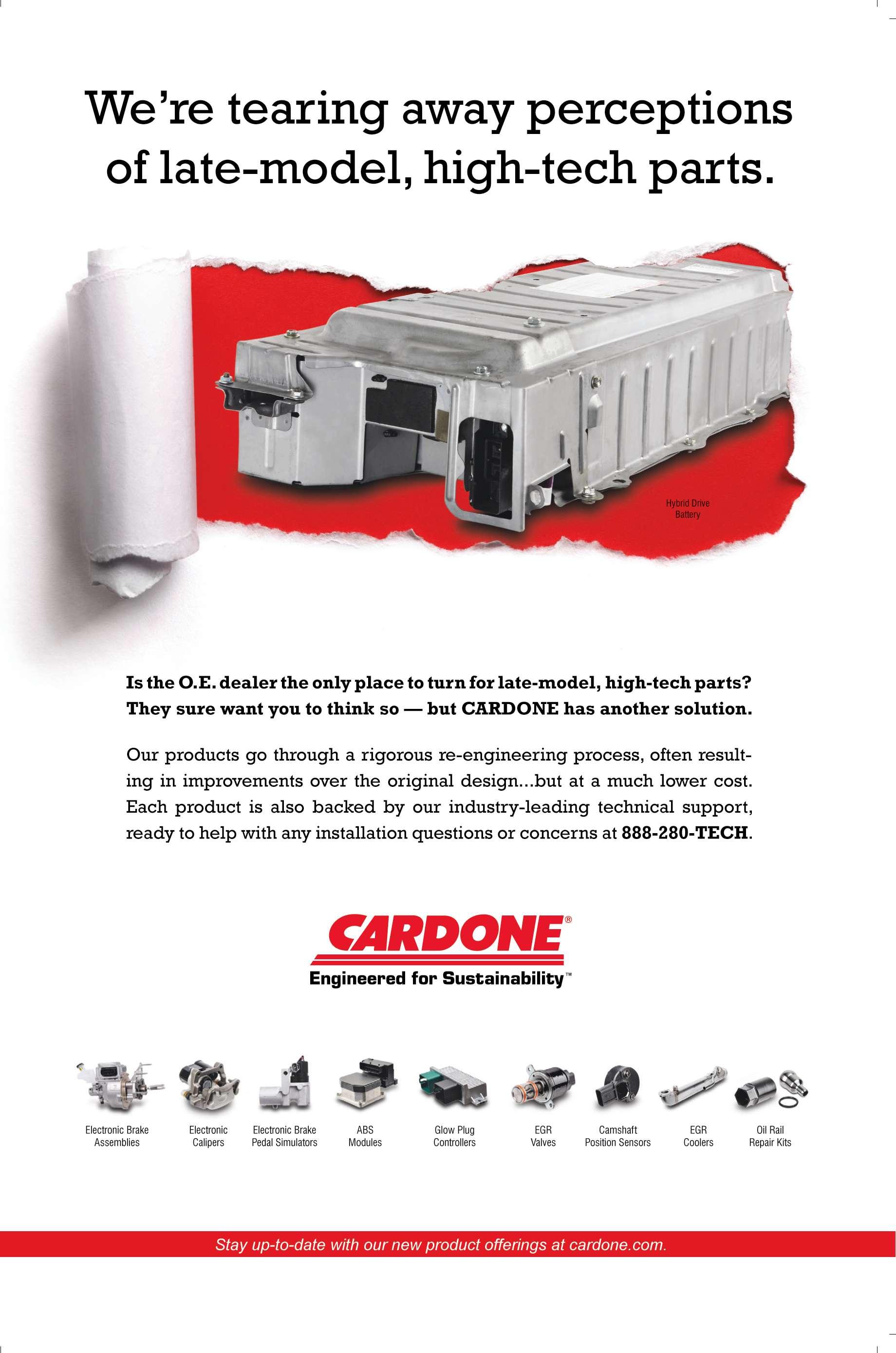
A Not-So-Remote Possibility
The Problem
Many late-model vehicles now use remotestyle power steering reservoirs, which incorporate a f ne-mesh screen to trap contamination and prevent it from entering the power steering system. The screen prevents contaminants from damaging healthy power steering components.
However, a major drawback to this design is that these reservoirs do not have bypass capability like an engine oil f lter does. This means that once the screen becomes clogged, the system begins to starve itself of power steering f uid, leading to noise, lack of assist and/or premature power steering pump failure.
As you can see in the photo shown here, the screen is almost completely obstructed and will not allow a suff cient f ow.

The Wrong Solution
Unfortunately, some vehicle owners and technicians punch a hole in the mesh screen to allow f uid to once again f ow freely into the pump. This may temporarily solve the problem, but is a very dangerous repair method. The debris that once was caught by the screen is now allowed to travel through the pump then the lines and into the spool valve of the steering unit. This will almost certainly cause future problems in the steering system. The OE engineers included the screen for a reason — do not damage this simple, but vital element of the system.
The Right Solution
The proper f x is to simply remove the reservoir and clean the screen with an aerosol carb or brake cleaner. Once the screen is cleaned, use low-pressure compressed air to ensure the cleaning f uid has fully evaporated. If cleaning chemicals contaminate the power steering system, they can seriously damage O-rings and seals.
Once the reservoir is completely dry, make sure the screen is clear by pouring fresh power steering f uid approved for that vehicle through the reservoir to ensure it f ows freely without restriction.
Before re-installing a reservoir on units that bolt directly to the pump, make sure you lubricate the new O-rings that were supplied with the pump with fresh power steering f uid.
For remote reservoirs that connect to the pump via a f ll hose, carefully inspect the hose to ensure it has not collapsed. Over time, it is common for this f ll hose to soften, which allows it to collapse and starve the pump for f uid, repeating the same problem the clogged screen presented. If the reservoir is damaged or cannot be cleaned properly, CARDONE offers many popular reservoir part numbers. ●

CARDONE Industries
Tech Advisor Hotline at 888-280-TECH (8324). www.cardone.com
Scan for a video version of this article:
Maximizing the Performance and Lifespan of Your Air Tools
Purchasing a high quality air tool, rather than those from a discount tool store, is an investment. With proper care, these tools can provide you with years of service.
There are several factors which effect how well your tools perform. Of course there’s the obvious, plentiful clean air. Air tools are designed to operate at 90 psi. Increasing the psi will not necessarily increase performance; on the contrary, it may decrease performance Rusty inlet motorand possibly damage liner. the tool.
In a world of adequate pressure and air supply, there are still several things to remember which can help increase the performance and lifetime of your tool.
Oiling daily is the big one. Air motors run at high rpms, and with an impact tool that means stopping and restarting with each blow of the hammer on the anvil. This Rusty rotor. starting and stopping requires adequate lubrication to ensure that the air motor can reach top speed prior to striking the next blow.
Any reduction in the motor reaching top speed is a reduction in power. Lubrication not only lines the motor cylinder, but also the rotor blades which continually move in and out of their slots in the rotor to catch and release the air passing through.
A blade stuck in its tracks will seize the motor. Oiling your tool daily not only allows all the moving parts to work properly, but to also prevent rust on the motor cylinder.
This rust, a result of poor quality air and not oiling the tool daily, will slow the motor and increase wear on the rotor blades as they scrape along the rusty motor cylinder rather than gliding smoothly.
Prematurely worn blades can be replaced and should be included with a tune-up kit along with other consumable parts such as O-rings and gaskets. Various worn
Now that your tool blades. is properly lubricated and running at peak performance, there is one other trick to getting maximum torque.
When testing tools on our Skidmore test f xture, I noticed something you will not notice in the f eld.
The more you grip and hold the tool f rmly, the lower the maximum torque will be. To maximize a tools torque, it’s best to let it “f oat” on the fastener. This can increase torque by up to 10%.
Now that know you why a tool should be oiled daily and how to improve performance, your investment will bring you years of trouble-free use. ●

Chicago Pneumatic
1800 Overview Dr. Rock Hill, SC 29730 803-817-7349 800-624-4735 www.cp.com

Save Your Customers from Battery Breakdown
Your customers would never get stranded with a dead battery, not if they knew when their batteries were going to fail.
Instead, people suffer battery breakdowns — especially in the winter. These wouldbe customers get help from their working spouses, roadside service providers or any passersby who happen to have jumper cables. After the headache and hassle, that’s when they know to replace their batteries.
Save them from the headache and hassle simply by testing the health of every battery that passes through your shop.
It’s especially important before and during winter. Every year, 25% of the cars on the road have a battery failure and most of those happen between November and February.
Just like any other replacement part, batteries wear out over time. However, winter weather has a way of dealing the f nal blow to weak batteries. Cold temperatures slow

down the electrochemical processes inside the battery and make engines harder to turn over. What might have been a passable battery in August is a failure risk come December.
Professional service shops testing every car battery help their customers dodge battery breakdowns. With a quick test, a technician can discern whether their customer’s battery is good, needs charging or should be replaced. In fact, today’s highend battery analyzers can test the battery and the electrical system in minutes.
Regular battery testing saves your customers from battery breakdowns — and helps you create positive impressions with your customers. Good battery test results give your customers peace of mind while creating a good impression of the technician who gives the good news. Weak battery test results give you the chance to be proactive and replace their battery.
Winter temperatures aren’t the only thing that can f nish off a car battery. Short commutes, idling in traff c, more power-hungry devices being plugged into the DC outlet — all of these can threaten your customers’ batteries.
Proactively testing car batteries puts you in a unique position as a trusted expert. You become the f rst choice for your customers when any of these factors come up.
Cut down your customers’ chances of a battery breakdown by testing every battery. Be dependable for your customers. They will be glad you are. ●
Interstate Batteries
12770 Merit Dr., Suite 1000
Dallas, TX 75251 www.interstatebatteries.com
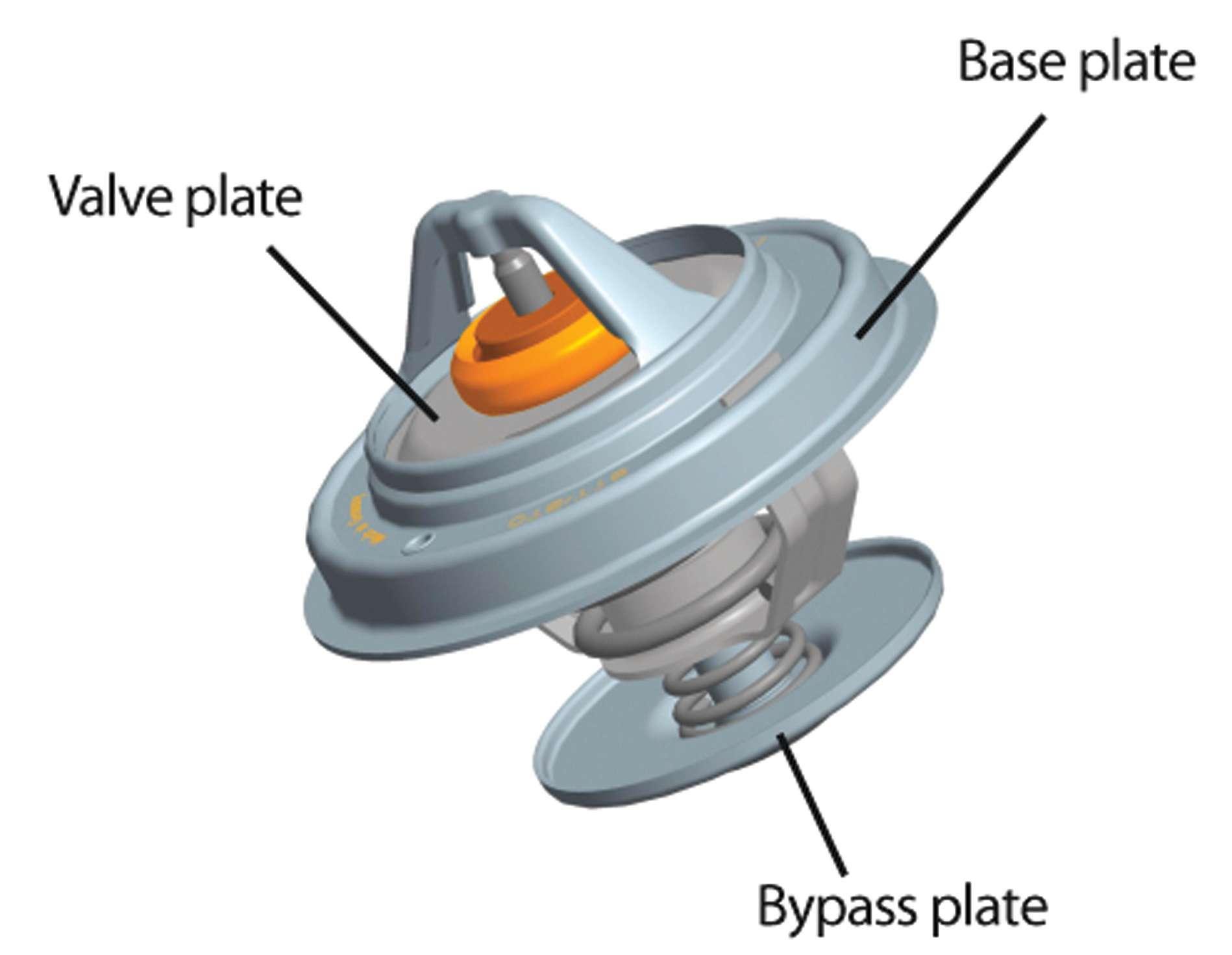
Thermostats: Controlling the Heat
There are many different types of automotive thermostats: thermostat inserts, integral thermostats, housing thermostats, electrically assisted thermostats, and bypass thermostats to name a few.
And, they all perform essentially the same function: to ensure that coolant f ow temperature is controlled effectively.
This way, operating temperatures can be swiftly reached and controlled. This reduces fuel consumption, wear and pollution, and increases occupant comfort, since the vehicle heats up more quickly. The thermostat also acts to restrict the f ow of coolant for effective thermal transfer. Thermostats are generally easy to install, but check the vehicle’s manual for specif c installation instructions. Here are several common probParts of a thermostat insert. lems that may be caused by incorrect installation: Many thermostat inserts and housings come with an integral seal and chemical sealants should not be used. Chemical sealants can trigger chemical reactions, including swelling that can destroy the seal. When installing, make sure the sealing surface is clean and completely free of debris. The integral seal is all that is needed for proper sealing. On electrically assisted thermostats, the heating element is frequently mistaken for a temperature sensor. Removal Problem: Leaking thermostat housing. of the spring destroys Possible cause: Use of the connection of sealant. the heating element,
making the thermostat non-functional.
Over tightening the attachment fasteners can cause hairline cracks in the thermostat housing. Over tightenProblem: Thermostat ing can be caused by does not open/system a false torque reading becomes too hot. Possible cause: Connecwhen tightening the tion heating element screws or by the use removed. of additional sealant. Lumpy residual sealant or broken plastic parts, e.g. water pump impeller blade fragments, can get lodged in the thermostat and impede the proper function. This happens frequently since the thermostat
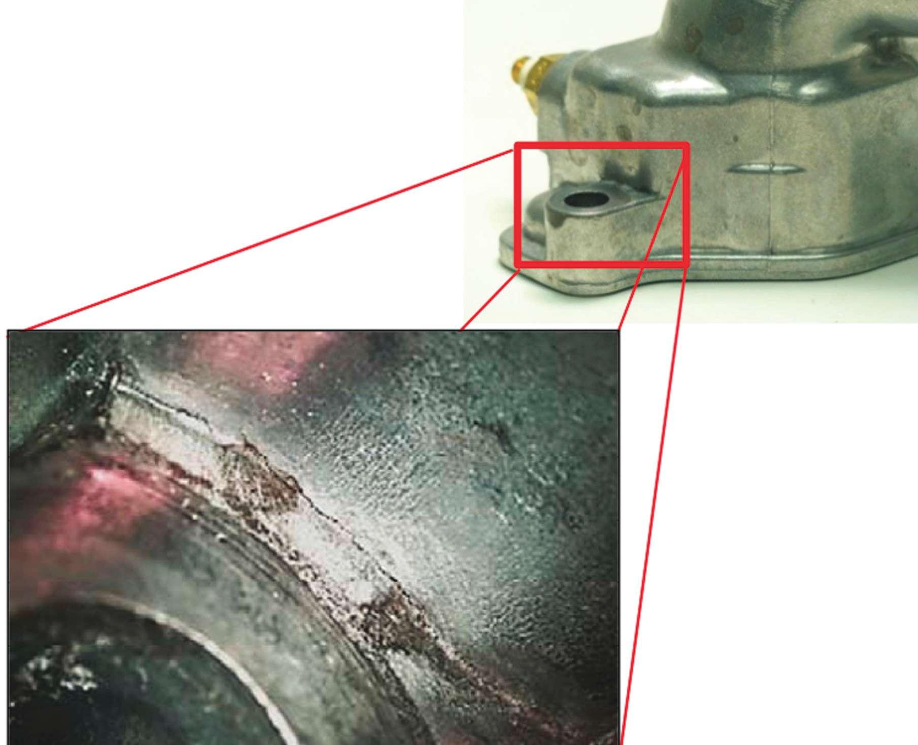
Problem: Leaking thermostat housing. Possible cause: Incorrect installation torque used. has some of the smallest passages in the cooling loop and acts as a “strainer.” ●
MAHLE Aftermarket Inc.
23030 MAHLE Dr. Farmington Hills, MI 48335 248-347-9714 / FAX: 248-596-8899 www.mahle-aftermarket.com

A Tech Tip from Motorcraft Mike
Recently while working on a vehicle I noticed that the upper radiator hose was collapsed. After I started the vehicle and it reached operating temperature, the pressure of the cooling system operation caused the hose to balloon so it looked like an overstuffed sausage.
Obviously, the hose needed replacement. Since the vehicle was 10 years old and still had the original hoses installed, I f gured it was time to replace them. However, even an old hose should not collapse when cold then over-expand during operation.
This symptom made me think some other fault might be at work as well.
This led me to take a look at the coolant degas system found on modern vehicles. This pressurizes the cooling system and also eliminates air in the system and provides coolant recovery.
Understanding possible causes
Let’s take a look at how this process works to understand the possible cause of the upper radiator hose collapse.
Air acts as an insulator that traps heat in the engine.
Therefore, coolant systems shouldn’t have any air in order to effectively cool the engine.
Coolant expands as temperature increases, creating pressure. At a specif c pressure level, the degas bottle cap opens and allows coolant to move from the radiator into the bottle.
When the engine is shut off, the coolant in the radiator cools and contracts. Since the coolant is taking up less space in the radiator, a vacuum is created.
A degas bottle cap has a vacuum valve that opens to atmospheric pressure in this

instance, allowing coolant in the bottle to be drawn back into the radiator.
When the vacuum valve in the cap or its seal fails, coolant cannot be drawn from the coolant recovery bottle. This causes a vacuum to be created in the cooling system and may cause the upper radiator hose to collapse.
The normal testing procedure for a degas bottle cap is to place it under pressure to see if it holds the pressure printed on the cap. But most testers do not test the opera
tion of the vacuum valve.
Other possibilities and cures
Now there are also other possibilities for a collapsed upper coolant hose, such as a plugged or restricted cooling system component or radiator.
But often replacement of the degas bottle cap will cure the problem.
And remember, cooling system components for Ford and Lincoln vehicles can be ordered anytime at FordParts.com. ●

FordParts.com
16800 Executive Plaza Drive Dearborn, MI 48126 www.fordparts.com
Why Wheel Balance is Important
Did you know that an average passenger car wheel assembly weighs about 40 pounds and that the average amount of assembly imbalance is only .75 ounce? That means that the average assembly is 98.2% perfect — but 1.8% imperfect. That doesn’t sound like much does it? But did you also know that at 65 mph a wheel assembly rotates 14 times per second, and an imbalance of just .75 ounce causes the wheel assembly to hop up and then down on every single rotation with more than 13 pounds of force? That’s equal to a sledgehammer banging on the vehicles suspension 14 times per second! The constant knocking can cause the car to vibrate and sway, loose traction when in corners, affect braking distance, increase fuel consumption and decrease overall tire life. In other words, that small amount of imbalance can cause a large amount of problems!
When you are balancing a vehicle’s wheel assemblies, it is critical to do the job right. The safety of your customer’s vehicle is at stake. Here are some quick tips to ensure you are properly balancing every wheel. Properly identify the wheel
Is it a steel or alloy rim? Is it the OEM wheel or an aftermarket wheel? Does it have inner and outer f anges with clip-on weights or does it use adhesive weights on the inside? Answering these questions on the front end is critical to ensuring that you properly balance the assembly. Use a rim gauge
If you will be installing clip-on weights, always use a rim gauge to ensure you are installing the correct wheel weight clip type. In a lot of garages they use “MC” weights on all alloy wheels because they think “MC” stands for “Most Cars.” This couldn’t be further from the truth! Using the proper clip-on weight that is made

to f t each rim’s different f ange style is important to ensuring the safety of that assembly. If your mantra is “hit it hard enough to make it work,” then you are in serious need of a rim gauge! Clean the area
If you will be installing adhesive weights, always clean the area where you will be installing the weight. Cleaning the rim surface with a rag and a cleaning agent will help ensure proper adhesion. Use the correct tools
Plier-grip style hammers have been the standard installation tool for clip-on wheel weights. However, a slight miss can cause damage to the wheel. For non-lead wheel weights, you also can cause the coating on the wheel weight to crack and speed up the process of corrosion. To prevent damage, it is always best to use a soft-tip hammer to install clip-on wheel weights. ●
Perfect Equipment
1715 Joe B Jackson Parkway Nolensville, TN 37127 Service First Line: 888-215-4575 www.perfectequipment.com
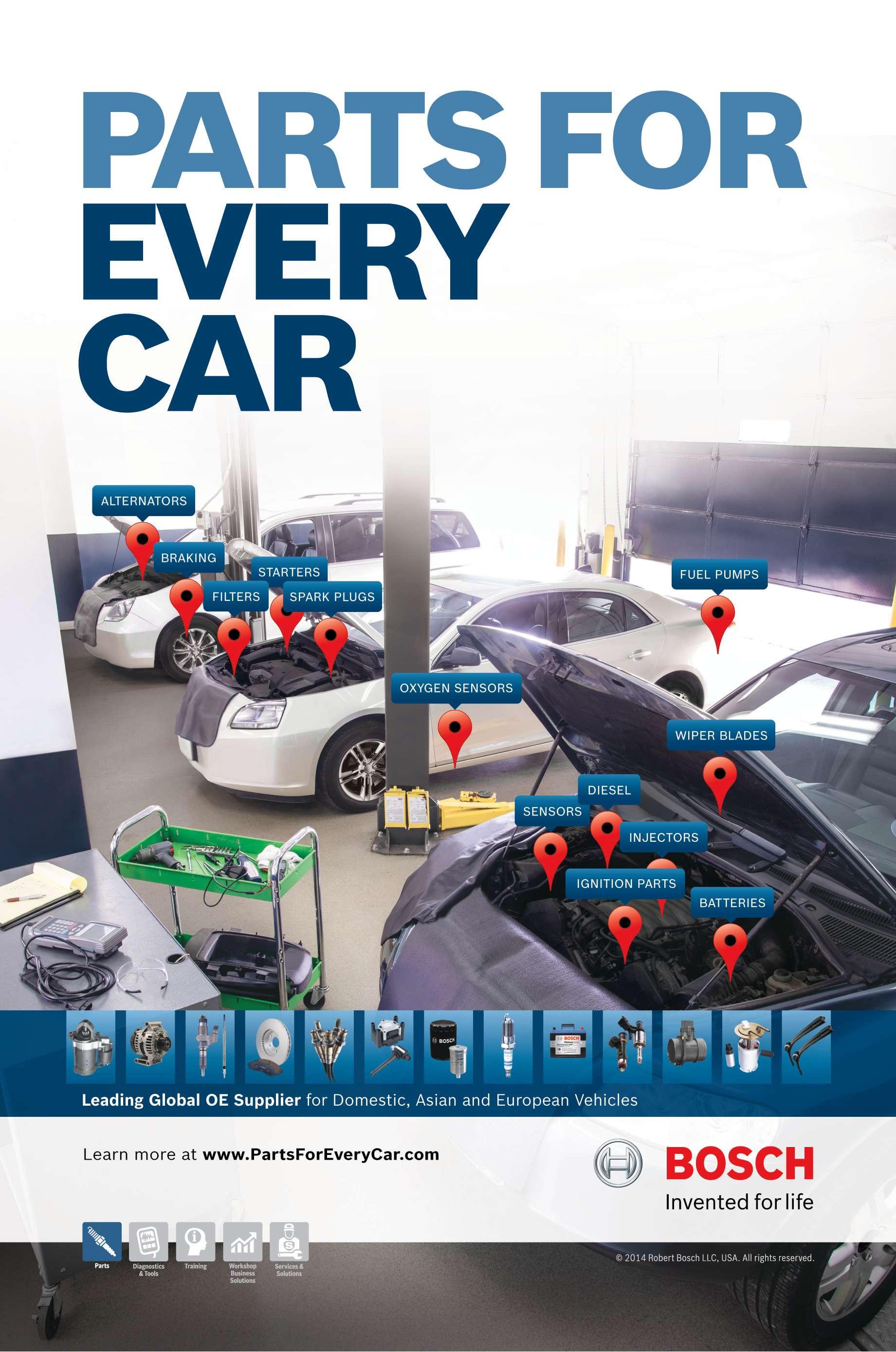
Starting System Problems On Your Customer’s Vehicle?
Follow These Steps to Diagnose a Fault
Before attempting any diagnosis of a vehicle’s starting system, be sure that the battery is properly charged and that all the cable connections are clean, free of corrosion and tight. If the cable ends are corroded, replace the entire battery cable. Also, check the condition of the ground strap from battery to engine, frame and body. All connections must be clean and tight.
Ideally, terminal voltage OCV for maintenance-free batteries must be 12.6 volts at 100% charge. A minimum of 12.4 volts at 75% charge is necessary to test the system properly. Terminal OCV of new batteries must register a minimum of 12.5 volts before installation. If a battery does not meet the requirements above, recharge and retest per the manufacturer’s specif cations.
With the battery properly charged, start the engine and listen to how well the starter turns the engine over. • If you hear any unusual noises, inspect the engine ring gear or the pinion gear of the starter and, if either is damaged, remove and replace it. • If the engine starts poorly or not at all, check the engine compression, ignition and fuel system. • If the engine cranks slowly or not at all, perform the following fault diagnosis.
With a properly charged battery, and while cranking:
1. Check the voltage at the battery terminal of the solenoid switch. It should be at least 9.6V or to the manufacturer’s specif cation. If it is not, check for a voltage drop between the battery and the starter solenoid battery terminal. Clean the battery posts or replace the battery cables. Entire cables should be replaced versus repairing only the battery cable ends. 2. Check the voltage at the starter terminal. It should also have a minimum of 9.6V (while cranking). If it does not, remove and clean the cable connections. If cleaning does not cure the problem, the starter solenoid is defective and should be replaced. 3. Perform a “Voltage Drop Test” using a digital volt meter. Place the positive probe on the starter case and the negative probe on the negative battery post. If the reading exceeds .1 volt, clean or replace the battery-to-engine cable or connection.

Finally, if the engine manufacturer’s specif cations are available, use a current/voltage tester to check the starting system circuits individually. Also check the engine’s mechanical condition, ignition and fuel system and oil viscosity and temperature, as all of these will affect the outcome of the tests performed on the vehicle’s starting system. ●

Robert Bosch LLC
2800 S. 25th Ave. Broadview, IL 60155 708-865-5200 www.boschautoparts.com

Steps to Performing a ‘Complete’ Brake Service
Follow a Systematic Process
What is a “complete” brake service? A complete brake service restores a vehicle’s braking system to its original operating condition. New technology such as Electronic Stability Control (ESP) depends on the basic braking system being in good operating condition and does not know if the system was serviced correctly the last time around.
The success of any brake service depends on many factors, but should always follow a systematic process to ensure you see the overall condition of the braking system and don’t miss anything. Here are the steps at a high level: 1. Perform a complete initial brake inspection looking for unusual brake wear issues. Look for uneven pad wear and leaking hydraulic components; check the brake lines and hoses, etc. 2. Replace or resurface rotors and/or drums according to the manufacturer’s recommendations. 3. Inspect and/or replace brake hardware according to the manufacturer’s recommendations. 4. Inspect and/or replace the brake f uid according to the manufacturer’s recommendations. 5. Install replacement brake parts that properly f t the vehicle. 6. Road test the vehicle after the brake service to ensure that the brakes are in proper operating condition. (Here’s a tip, an infrared temperature gun can help determine if all four brakes are operating correctly following a brake service.)
Why did we add the need to check for proper f tting brake parts during brake service to our list? If you use a set of brake pads that were not designed to f t the vehicle in the f rst place, these pads will “walk” in the caliper bracket and might cause a clicking sound when the driver is braking in forward or in reverse. Even if the technician uses some brake pad glue to hold it in place, the small size of the brake pad can very easily cause the adhesive to break loose A properly f tting brake pad, the right from the caliper and move/ length and f tting walk from front to back correctly in the or top to bottom. The key caliper bracket. is to select a properly f tting brake pad that has the right length and f ts correctly in the caliper bracket.
Always remember to check replacement parts to see that they f t properly and if something does not look right stop and ask some questions. You can perform really top notch The brake pad, seen brake service, but if the here, is not f tting correctly and shows parts do not f t correctly it extra space at the might end up as a cometop of the pad. back, which will cost you time, money and customer conf dence. ●
Robert Bosch LLC
2800 S. 25th Ave. Broadview, IL 60155 708-865-5200 www.boschautoparts.com/brakes