15.4COMPLETEHYDRAULICCYLINDERASSEMBLY...........60
15.4.1HYDRAULICCYLINDERREBUILDKIT..............61
15.5 ”R”PUMPASSEMBLY............................62 15.5.1”R”PUMPREBUILDKITS......................65 15.6 ”A”PUMPASSEMBLY............................67
15.6.1”A”PUMPREBUILDKITS......................70
15.7 PUMP-LINEASSEMBLY...........................74 15.7.1PUMPBASEREPAIRKIT......................75
15.8 INLETMONITORINGASSEMBLY.....................76
15.9 Y-STRAINERASSEMBLY”A”SIDE....................77
15.10Y-STRAINERASSEMBLY”R”SIDE....................78
15.11HEATERASSEMBLY.............................79
15.11.1HEATERTHERMOCOUPLEKIT..................85
15.12PRESSURETRANSDUCERASSEMBLY..................85
15.13BLEEDVALVEKIT.............................. 86
15.14MOTOR-LINEASSEMBLY..........................87
15.15TRANSFORMERCOVERASSEMBLY...................89
15.16FRAMEASSEMBLY.............................91
15.17FINALASSEMBLY.............................. 93
15.18PH(X)-25/PH(X)-40HOSES.........................96
15.18.1HALFINCHHOSEKIT........................96
15.19LUBEBOTTLECOMPONENTS......................97
1 WARRANTY PolyurethaneMachineryCorporation(hereinafter“PMC”)providesthis LIMITED WARRANTY (hereinafter“Warranty”)totheoriginalpurchaser(hereinafter“Customer”) coveringthisequipmentandtheoriginalPMCmanufacturedaccessoriesdeliveredwiththe equipment(hereinafter“Product”)againstdefectsinmaterialorworkmanshipoftheProduct (hereinafter“Defect”or“Defective”)foraperiodofone(1)yearfromthedateoffirst purchaseasshownontheoriginalPMCinvoice(hereinafter“WarrantyPeriod”)
IfduringtheWarrantyPeriodundernormaluse,theProductissuspectedbyCustomertobeDefectiveinmaterialorworkmanship,itisCustomer’sresponsibilitytocontact PMCandreturntheProducttoPMCasdirectedbyPMC,freightprepaid.IfPMCdeterminesthattheProductisDefectiveandthatsuchDefectiscoveredbythisWarranty,PMC willcreditCustomerforthereasonablefreightchargesincurredbyCustomerinreturning theDefectiveProducttoPMC,andPMC(oritsauthorizedagent)will,atPMC’soption, repairorreplacetheProduct,subjecttothefollowing:
1. OriginalInvoice: Theoriginalinvoicemustbekeptasproofofthedateoffirstsaleand theProductserialnumber.TheWarrantydoesnotcoveranyProductiftheOriginal Invoiceappearstohavebeenmodifiedoraltered,orwhentheserialnumberonthe Productappearstohavebeenalteredordefaced.
2. ProductMaintenance: ItistheCustomer’sresponsibilitytomaintaintheProductproperly.Seeyourmaintenancescheduleandowner’smanualfordetails.TheWarranty doesnotcoveranimproperlymaintainedProduct.
3. Non-PMCComponentsandAccessories: Non-PMCmanufacturedcomponentsandaccessoriesthatareusedintheoperationoftheProductarenotcoveredbythisWarranty.Suchcomponentsandaccessoriesshallbesubjecttothewarrantyofferedtothe Customer,ifany,bytheoriginalmanufacturerofsuchcomponentoraccessory.
4. OtherWarrantyExclusions: TheWarrantydoesnotcoveranyProductthatPMCdetermineshasbeendamagedorfailstooperateproperlyduetomisuse,negligence, abuse,carelessness,neglect,oraccident.Bywayofexampleonly,thisincludes:
• Normalwearandtear.
• Improperorunauthorizedinstallation,repair,alteration,adjustmentormodificationoftheproduct.
• Useofheatingdevices,pumpingequipment,dispensers,orotherpartsoraccessorieswiththeproductthathavenotbeenapprovedormanufacturedbyPMC.
• Failuretofollowtheoperatinginstructionsandrecommendationsprovidedby PMC.
• Cosmeticdamage.
• Fire,flood,“actsofGod,”orothercontingenciesbeyondthecontrolofPMC.
THEWARRANTYDESCRIBEDHEREINISTHEEXCLUSIVE REMEDYFORTHECUSTOMERANDISINLIEUOFALLOTHER WARRANTIES,EXPRESS,IMPLIED,STATUTORYOROTHERWISE,AND THEIMPLIEDWARRANTIESOFMERCHANTABILITYANDFITNESS FORAPARTICULARPURPOSEANDALLOTHERWARRANTIESARE HEREBYDISCLAIMED.TOTHEFULLESTEXTENTPERMITTEDBY LAW,PMCSHALLNOTBERESPONSIBLE,WHETHERBASEDINCONTRACT,TORT(INCLUDING,WITHOUTLIMITATION,NEGLIGENCE), WARRANTYORANYOTHERLEGALOREQUITABLEGROUNDS,FOR ANYCONSEQUENTIAL,INDIRECT,INCIDENTAL,LOSTPROFITS,SPECIAL,PUNITIVEOREXEMPLARYDAMAGES,WHETHERTOPERSON ORPROPERTY,ARISINGFROMORRELATINGTOTHEPRODUCT, EVENIFPMCHASBEENADVISEDOFTHEPOSSIBILITYOFSUCH LOSSESORDAMAGES.
• Non-WarrantyServicebyPMC: IfPMCdeterminesthatthesuspectedDefectofthe ProductisnotcoveredbythisWarranty,dispositionoftheProductwillbemadepursuanttothetermsandconditionsofPMC’swrittenestimateonatimeandmaterials basis.
• ContinuingWarrantyforProductsRepairedorReplacedunderWarranty: Following therepairorreplacementofaProductcoveredbythisWarranty,suchProductwill continuetobesubjecttotheoriginalWarrantyfortheremainderoforiginalWarranty Periodorforthree(3)monthsfromtherepairorreplacementdate,whicheverislonger.
• NoRightsImplied: Nothinginthesale,leaseorrentalofanyProductbyPMCshall beconstruedtograntanyright,interestorlicenseinorunderanypatent,trademark, copyright,tradesecretorotherproprietaryrightormaterialownedbyanyone;nor doesPMCencouragetheinfringementofsame.
• ExclusiveWarranty: Thiswritingisthefinal,complete,andexclusiveexpressionof theWarrantycoveringtheProduct.AnystatementsmadebyPMC,itsemployeesor agentsthatdifferfromthetermsofthisWarrantyshallhavenoeffect.Itisexpressly understoodthatCustomer’sacceptanceofthisWarranty,byperformanceorotherwise, isuponandsubjectsolelytothetermsandconditionshereof,andanyadditionalor differenttermsandconditionsproposedorexpressedbyCustomeroranyone,whether inwritingorotherwise,arenullandvoidunlessspecificallyagreedtoinwritingbyan OfficerofPMC.
2 SAFETYANDHANDLING Thischaptercontainsimportantinformationonthesafety,handling,anduseofyour PHSeriesProportioner.
BeforeinstallingthePHSeriesProportionerandstartup,carefullyreadallthetechnicalandsafetydocumentationincludedinthismanual.Payspecialattentionto theinformationinordertoknowandunderstandthe operationandtheconditionsofuseofthePHSeries Proportioner.Alloftheinformationisaimedatimprovingusersafetyandavoidingpossiblebreakdowns fromtheincorrectuseofthePHSeriesProportioner.
WARNING! Symbolispresentedinfrontofinformationto alertofasituationthatmightcauseseriousinjuriesiftheinstructionsarenotfollowed.
CAUTION! Symbolispresentedinfrontofinformationthat indicateshowtoavoiddamagetotheproportionerorhowtoavoid asituationthatcouldcauseissues.
NOTE! Symbolispresentedinfrontofrelevantinformation ofaprocedurebeingcarriedout.
Carefulstudyofthismanualwillenabletheoperatortoknowthecharacteristics ofthePHSeriesProportionerandtheoperatingprocedures.Byfollowingtheinstructions andrecommendationscontainedherein,youwillreducethepotentialriskofaccidentsinthe installation,use,andmaintenanceofthePHSeriesProportioner.Youwillprovideabetter opportunityforgreateroutput,incident-freeoperationforalongertime,andthepossibility ofdetectingandresolvingproblemsquicklyandsimply.
KeepthisOperationsManualforfutureconsultationofusefulinformationatall times.Ifyoulosethismanual,askforanewcopyfromyourPMCServiceCenterorgoon lineatourwebsite(www.polymacusa.com).
ThePHSeriesProportionerhasbeendesignedandbuiltfortheapplicationof polyureachemicalsystems,polyurethanefoamchemicalsystems,andsometwo-component epoxysystems
WARNING! ThedesignandconfigurationofthePHSeries Proportionerdoesnotallowitsuseinpotentiallyexplosiveatmospheresorthepressureandtemperaturelimitsdescribedinthe technicalspecificationsofthismanualtobeexceeded.
Alwaysuseliquidsandsolventsthatarecompatiblewiththeunit.Ifindoubt, consultyourauthorizedPMCdistributor.
WhenworkingwiththePHSeriesProportioner,itisrecommendedthattheoperator wearsuitableclothingandelementsofpersonalprotection,including,withoutlimitation, gloves,protectivegoggles,safetyfootwearandfacemasks.Usebreathingequipmentwhen workingwiththePHSeriesProportionerinenclosedspacesorinareaswithinsufficient ventilation.Theintroductionandfollow-upofsafetymeasuresmustnotbelimitedtothose describedinthismanual.BeforestartingupthePHSeriesProportioner,acomprehensive analysismustbemadeoftherisksderivedfromtheproductstobedispensed,thetypeof application,andtheworkingenvironment.
Topreventpossibleinjurycausedbyincorrecthandlingofthe rawmaterialsandsolventsusedintheprocess,carefullyread theMaterialSafetyDataSheet(SDS)providedbyyoursupplier. Dealwiththewastecausedaccordingtocurrentregulations.
Toavoiddamagecausedbytheimpactofpressurizedfluids,do notopenanyconnectionorperformmaintenanceworkoncomponentssubjecttopressureuntilthepressurehasbeencompletely eliminated.
Usesuitableprotectionwhenoperating,maintainingorbeing presentintheareawheretheequipmentisfunctioning.Thisincludes,butisnotlimitedto,theuseofprotectivegoggles,gloves, shoesandsafetyclothingandbreathingequipment.
Theequipmentincludescomponentsthatreachhightemperatures andcancauseburns.Hotpartsoftheequipmentmustnotbe handledortoucheduntiltheyhavecooledcompletely.
Topreventseriousinjurythroughcrushingoramputation,do notworkwiththeequipmentwithoutthesafetyguardsinstalled onthemovingparts.Makesurethatallthesafetyguardsare correctlyreinstalledattheendoftherepairormaintenancework oftheequipment.
3 CHARACTERISTICS ThePHSeriesProportionerhasbeendesignedandbuiltfortheapplicationof polyureachemicalsystems,polyurethanefoamchemicalsystems,andsomespecifictwocomponentepoxysystems.
3.1 PRINCIPALHEATINGSYSTEM TheProportionerconsistoftwo(2)independentMaterialHeaterswithoutinternal seals.EachheaterforthePH(X)-40Proportionerhassix(6)HeatingElementsratedat1,250 1,500or1,750wattseach,givingtheProportioneratotalheatof15,000,18,000or21,000 watts.TheMaterialHeatersystemsforallPHSeriesProportionerscontainthenecessary controlandsafetycomponentsfortheirpreciseoperation.TheMaterialHeaterdesignallows atemperaturedifferential(DeltaT)of90oF(32oC)andmaterialapplicationtemperatures ofupto190oF(88oC)undernormalambienttemperatures.
3.2 HOSEHEATINGSYSTEM ThePH(X)-40Proportionerisdesignedwitha5kVA(120V)IsolationTransformer thatenableseffectiveheatingofuptoatotalhoselengthof410feet(123meters).Both systemsincludeaninnovativehoseheatingconceptinwhichthecontinuousbraidtinnedcopperjacketisdistributedevenlyaroundthecircumferenceofthehoseprovidingauniform heatingwattdensityandprecisecontrolofthematerialapplicationtemperature.Thishose heatingelementdesignisextremelyresistanttofatiguefailure.
3.3 DOUBLEACTINGOPPOSEDPISTONMETERINGPUMPS TheopposeddoubleactingPumpLineisdrivenbyadualrodHydraulicCylinder.Thein-linepumpsystemwithopposedpistonpumpsprovidesaconstantvolumeand guaranteesuniformpressuresinbothdirectionsofpumpmovement.Differentsizedpumps allowforvariousvolumetricratiostobeachieved(1:4to1:1to4:1)betweenthechemical componentsusedintheprocess.
3.4 PRESSUREBALANCECONTROLSYSTEM ThePressureBalanceControl(PBC)systemperformsanautomaticshutdownwhen achemicalimbalanceoccurs.Whenthesystemisturnedoff,theProportionerwillperform asifthereisnoPBCsystemandwillcontinuepumpingmaterial.Whenthesystemis turnedon,itwillcontinuallymonitorthepressurebetweenthetwochemicals(knownasthe pressuredifferential).Ifthepressuredifferentialbecomesequaltoorgreaterthanthe maximumallowablepressuredifferential,thepumpswillbeshutoff.
ThePressureBalanceControlsystemcanbesimplifiedintoalogicboxdiagram withinputsandoutputs.Therearefiveinputs:thepowersupplyfromthemainconsole,the pressurereadingsfromeachchemical,themaximumpressure,andthemaximumallowable pressuredifferential.Insidethelogicbox,theactualpressuredifferentialofthechemicalsis comparedtothemaximumallowablepressuredifferential.Dependingonthecircumstances ofallfiveinputs,thereareonlytwopossibleoutputs:eitherthepumpswillcontinueto pressurizeandmovematerial,orthepumpswillshutoffandflowwillbelost.
Figure1:PressureBalanceControlLogicDiagram
4.1 PH(X)-25ELECTRICAL
PH(X)-25,SinglePhase,208-240V
2,000PSI(PH-25)
3,000PSI(PHX-25)
PH(X)-25,ThreePhase,208-240V
2,000PSI(PH-25) 3,000PSI(PHX-25)
PH(X)-25,ThreePhase,400V
2,000PSI(PH-25) 3,000PSI(PHX-25)
MaterialHeaterPower PowerConsumption
4.0kW/side(2x2,000W/side) 8.0kW
5.0kW/side(2x2,500W/side) 10.0kW 6.0kW/side(2x3,000W/side) 12.0kW 7.0kW/side(2x3,500W/side) 14.0kW
HoseTransformer PowerConsumption
ElectricalMotor PowerConsumption
PH(X)-25 3hp
CAUTION! InsidetheconsoleisaTerminalStripforconnectingthemain power(wirenotsupplied)tothePHSeriesProportioner.Thiselectricalconnectionmustbemadeonlybyaqualifiedelectrician.
4.2 PH(X)-40ELECTRICAL PH(X)-40,SinglePhase,208-240V Pressure
12.0kW(6.0kW/side)
2,000PSI(PH-40)
3,000PSI(PHX-40)
PH(X)-40,ThreePhase,208-240V Pressure
2,000PSI(PH-40)
3,000PSI(PHX-40)
PH(X)-40,ThreePhase,400V
2,000PSI(PH-40)
3,000PSI(PHX-40)
MaterialHeaterPower PowerConsumption
6.0kW/side(3x2,000W/side) 12.0kW
7.5kW/side(3x2,500W/side) 15.0kW
9.0kW/side(3x3,000W/side) 18.0kW 10.5kW/side(3x3,500W/side) 21.0kW
HoseTransformer PowerConsumption
ElectricalMotor PowerConsumption PH(X)-40 5hp
CAUTION! InsidetheconsoleisaTerminalStripforconnectingthemain power(wirenotsupplied)tothePHSeriesProportioner.Thiselectricalconnectionmustbemadeonlybyaqualifiedelectrician.
4.3 PH(X)-25MECHANICAL 120Pumps 80Pumps
MaximumWorkingPressure 2,000PSI(14MPa,138bar) 3,000PSI(21MPa,207bar)
MaximumProduction 25lb/min(12.5kg/min) 1.4GPM(5.6L/min) @1,500psi @1,750psi
MinimumProduction 2.0lb/min(1kg/min)
GallonsperCycle 0.0312gal/cycle(0.1182L) 0.021gal/cycle(0.0786L)
Cyclesper55gal(200L)Drum 1,763cycles 2,619cycles
MaximumHoseLength
3kVATransformer 310ft(93m)
5kVATransformer 410ft(125m)
ApproximateWeight
HydraulicTankEmpty 420lbs(190kg)
HydraulicTankFull(20gal) 594lbs(269kg)
OverallDimensions(WxDxH) 40inx29inx52in(100cmx73cmx133cm)
4.4 PH(X)-40MECHANICAL 120Pumps 80Pumps
MaximumWorkingPressure 2,000PSI(14MPa,138bar) 3,500PSI(24MPa,241bar)
MaximumProduction 40lb/min(14kg/min) 2.5GPM(1.0L/min) @1,000psi @2,500psi
MinimumProduction 2.0lb/min(1kg/min)
GallonsperCycle 0.0312gal/cycle(0.1182L) 0.021gal/cycle(0.0786L)
Cyclesper55gal(200L)Drum 1,763cycles 2,619cycles
MaximumHoseLength
3kVATransformer 310ft(93m)
5kVATransformer 410ft(125m)
ApproximateWeight
HydraulicTankEmpty 420lbs(190kg)
HydraulicTankFull(20gal) 594lbs(269kg)
OverallDimensions(WxDxH) 40inx29inx52in(100cmx73cmx133cm)
PH(X)-25/PH(X)-40SERVICEMANUAL 4TECHNICALSPECIFICATIONS
Figure2:ProportionerDimensions
Figure3:ComponentIdentification-Front
A. ControlPanel -ControlsandregulatestheoperationofthePHSeriesProportioner.
B. Isocyanate(Iso,A)MeteringPump -MeterstheIsocyanatematerial.
C. Polyol(Poly,R)MeteringPump -MetersthePolyolmaterial.
D. Isocyanate(Iso,A)Heater -HeatstheincomingIsocyanatetoatemperaturesetby theoperator.
E. Polyol(Poly,R)Heater -HeatstheincomingPolyoltoatemperaturesetbythe operator.
F. HoseHeatingTransformer -SuppliestherequiredvoltageformaterialHeatedHoses.
G. HydraulicPressureGauge -IndicatesthepressureintheHydraulicDriveSystem.
H. Isocyanate(Iso,A)PressureGauge -IndicatesthepressureintheIsocyanatesystem.
I. Isocyanate(Iso,A)SafetyPressureSwitch -Disablesthepumpcircuitintheevent ofexcessivepressureintheIsocyanatesystem.
J. Isocyanate(Iso,A)Thermocouple -ProvidestemperaturereadingoftheIsocyanate chemical.
K. Polyol(Poly,R)PressureGauge -IndicatesthepressureinthePolyolsystem.
L. Polyol(Poly,R)SafetyPressureSwitch -Disablesthepumpcircuitintheevent ofexcessivepressureinthePolyolsystem.
M. Polyol(Poly,R)Thermocouple -ProvidestemperaturereadingofthePolyolchemical.
N. HydraulicPressureControl -Allowsthepressureofthehydraulicsystemtobeincreasedordecreased.Turnclockwisetoincreasethepressureandcounterclockwise todecrease.Toregulatethepressureofthehydraulicsystem,theNORMALorRETRACTPumpSwitchpositionmustbeselected. Figure4:ComponentIdentification-Back
O. Isocyanate(Iso,A)InletMaterialStrainer -Screens(60mesh)materialfrombulk supply.
P. Polyol(Poly,R)InletMaterialStrainer -Screens(60mesh)materialfrombulk supply.
Q. MainPower -TurnsONandOFFmainpowertothecontrolpanel.Itmustbeturned ONforanyoperationtobeperformedwiththeunit.WhenturnedON,theredpilot willlight.
R. EmergencyStop -InterruptsthePHSeriescontrolpowercircuittostopallmotion andheating.
S. ControlPower -TurnsONandOFFthecontrolpowertothecompleteelectricalcircuit includingHeatersandHoseHeaters.
T. HeaterTemperatureZones:A(Iso),R(Poly),HOSE -TurnsONandOFFpower tothespecificHeaters.Seepage27fordetailedTemperatureControllerinstructions. TheHoseHeatControllerautomaticallycontrolstheHoseHeateronlywhenusingthe TSU(TemperatureSensingUnit)probe.
U. CountDownCounter -Usedtosettheamountofcyclesrequiredtopreventthe chemicaldrumsfromrunningdry,themachinewillshutdownwhenthepresetcycle expires.ThereisandON/OFFswitchtoactivate/deactivatethisfeature.
Figure5:FrontPanelDescription
V. CycleCounter -Indicatesthenumberofpumpcyclestocalculatematerialusage.
W. MotorSwitch -TurnsOnandOFFtheElectric/HydraulicMotor.WhenturnedON theswitchwillbelit.Intheeventofamotoroverload,thepilotlightwillturnOFF andthemotorwillstop.
X. PumpSwitch
OFF -Removespowerfromthepumpcircuit.Thedirectionalindicatorlightswillnot belit.
NORMAL -Activatesthenormaloperationofthemachine.WhentheswitchisON thedirectionallightcorrespondingtothestrokedirectionwilllight.
RETRACT -SetsthePistonRodoftheA(Iso)meteringpumptotheretractposition andpreventscrystallizationofA(Iso)onthePistonRod.Turntheswitchtothe RETRACTpositioneverytimetheunitisstoppedbytheoperator.(see11,page32)
Y. DirectionIndicatorLight -IndicatesthedirectionofmovementoftheMetering Pumps.Ifexcessivepressureoccursinthesystem,thepumpcircuitwillbedisabled andthedirectionallightswillturnOFF.
Z. HeaterTemperatureSwitch:A(Iso),R(Poly),HOSE -TurnsONandOFF powertotherespectivespecificHeaters.
AA. AutoShutDownSwitch -TurnsONandOFFpowertotheAutoShutDownunit.
BB. PressureBalanceControl”FAULT”Light -Indicatesthethepressuredifferential isequaltoorgreaterthanthemaximumallowable.
CC. PressureBalanceControl”ON”Light -IndicatesthatthePressureBalance Controlsystemisonandfunctioning.
DD. PressureBalanceControlKnob -Usedtosetthemaximumallowablepressure differential(PSI)betweentheA(Iso)andR(Poly)pumps.Seepage26formore information.
6 INSTALLATION WARNING! UsesuitableprotectionandfollowtherecommendationsintheSafetyInformationenclosedandprovidedbymaterial supplierswheninstallingorworkingwiththeProportioner.
CAUTION! Makesurethepowercableisdisconnectedfromthe mainpowersourcebeforeconnectingtotheTerminalStripinthe Console.
NOTE! ToensurethePHSeriesProportionerworkscorrectly,the electricalsupplymustmeetthespecificationsindicatedontheSerialNumberPlacardaffixedtotheElectricalConsole.
1. Insertthemainpowercablebypassingitthroughthewirestopatthebottomofthe electricalconsoleandconnectasshowninthediagramabove.
2. FilltheHydraulicReservoirwith20gallons(76Liters)ofapprovedhydraulicfluid. Seepage56forhydraulicoilspecifications.
NOTE! Donotfillthetanktomaximumcapacity; usetheVisualLevelIndicatoronthetanktomake suretheamountofhydraulicfluidisnotmorethan 20gal(76L)or80%ofthetanksmaximumcapacity.
3. TocheckthelevelofthehydraulicfluidintheHydraulicPumpCase,disconnectthe HydraulicHosefromthe90degreefittingandremoveFittingfromHydraulicCase. Addfluidasrequired.ReattachFittingandHydraulicHose.Turnthehydraulic pressurecontrolknobcounterclockwiseuntilitstops,thatisthelowesthydraulic pressuresetting.
Figure6:ElectricalInstallation
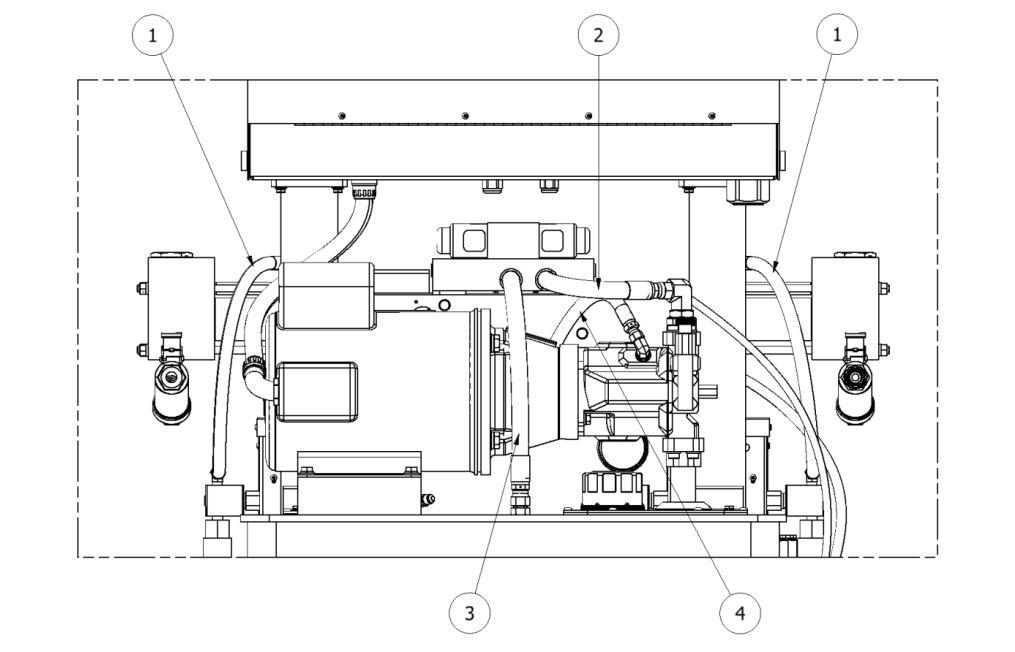
Figure7:ComponentIdentification-Misc
CAUTION! Ensurethattheemergencystopisnotengaged.
4. ThreePhaseProportionerOnly: ChecktheElectricMotortoensurerotationis clockwisewhenviewingtheendoftheElectricMotor.Acounterclockwiserotation indicatestwooftheincomingpowerleadsneedtobereversed.
CAUTION! EnsureMainPowerSwitchisOFFandincomingpowerislockedOFFbeforereversingpowerleads.
RecheckrotationbeforeproceedingwithInstallation.
5. FilltheLubeReservoirwithPMCPumpLubeorsuitabledilutents.Itisnotnecessary toprimethesystem.
6.1 HEATEDHOSEINSTALLATION CAUTION! ThematerialdeliveryHeatedHosesarecolorcoded RedandBlue,allowingtheusertorecognizethem.TheRedcorrespondstotheIsocyanate(Iso,A)andtheBluetothePolyol (Poly,R).Toavoidconnectionerrors,theCouplingConnectionsof theIso(A)andPoly(R)HeatedHosesaredifferentsizestoensure correctorientation.
NOTE! ThematerialdeliveryHeatedHosesarecappedatthe endstopreventabsorbingmoisture.Donotremovecapsuntil theHeatedHosesaregoingtobeinstalledontheProportioner.
1. LayoutalltheHeatedHoseassembliesendtoendaligningtheIso“A”(red)andPoly “R”(blue)andconnecttherespectiveCouplingConnectionsusingtheappropriate sizedopen-endwrenchafterensuringHeatedHoseassemblieslayflat.
CAUTION! Takecaretonotcross-threadorover-tighten theCouplingConnections.ThreadsealtapeorcompoundisnotrecommendedforthesetaperedseatCouplingConnections.
2. ConnectthematerialHeatedHosestotheoutletsoftherespectiveHeatersi.e.Iso (A)HeatedHosetotheIso(A)HeaterandthePoly(R)HeatedHosetothePoly(R) HeaterensuringHeatedHoseassemblieslayflat.(Forhalfinchhoseassemblies,all requiredfittingsandinstructionsareincludedinkit200212)
3. ConnectAirHoseCouplingConnections.
4. ConnecttheHeatedHosepowerwirestothe“Fast-Lock”Connector(Part#KT00029A)comingfromtheHoseHeatTransformerasfollows:
(a) LoosentheSocketHeadSetScrewtoallowinsertionoftheHeatedHoseelectrical wireTerminal.
(b) InserttheTerminalintothe“Fast-Lock”ConnectorBody.
(c) SecurelytightentheSocketHeadSetScrew.
(d) InstallelectricaltapearoundConnectorBody.
NOTE! Agoodpracticeistoaddsomedielectricgrease (Permatex67VRorequivalent)totheoutsideofthe Terminal,wheretheelectricalconnectionismade,prior toinsertion.
5. Repeattheabovestepstoconnectthe“Fast-Lock”Connectorsthatyouwillfindon allHeatedHosepowerwire.
CAUTION! EnsurethepropermechanicalandelectricalconnectionsoftheHeatedHosesaremadetoavoid possiblematerialleakageandHoseheatproblems.
6. ItisrecommendedtheTSUbeinstalledbetweenthelastsectionofHeatedHoseand theGunWhip.Carefullystraightenthesensingwire,insertingitintheIso(A)Heated Hoseandtightenfluidfittingswithappropriatesizedopen-endwrenches.
CAUTION! ToprotecttheTSUsensor,youmustpay specialattentionnottokinkorexcessivelybendthe HeatedHoses.DonotcoiltheHeatedHoseswitha diameteroflessthan4feet(1.22Meters).
Figure8:TemperatureSensingUnit
(TSU)Part#EL-51A-4
ReplacementSensorPart#EL-51A-2
CAUTION! ConnectingtheTSUbetweenthefirstand secondsectionofHeatedHoseresultsintheTSUsensing thematerialtemperatureexitingtheHeaterandnotthe insideoftheHeatedHoseneartheSprayGun.
7. EnsuretheManualValvesareCLOSEDandconnecttheCouplingBlocktotheHeated GunWhip.
CAUTION! ExcessiveforceclosingoropeningtheManualValvesmayresultindamagetotheManualValves and/orCouplingBlock.
8. ConnecttheTransferPump/HeatedHoseAssemblies/AirSupplyandAirDryersystemsasrequired.ReviewtheInstallationInstructionsforeachtoensureproperset-up andoperation.
9. InstalltheMaterialTransferPumpsasfollows:
WARNING! IfTransferPumpshavebeenpreviouslyused,pay specialattentiontoconnecteachPumptoitsspecificmaterial. InadvertentlychangingtheTransferPumpswillcauseachemical reactionrenderingthemuseless.
NOTE! PlacingatapeofthesamecolorasoftheMaterialDeliveryHoses(redfortheIso(A),blueforthePoly (R))oneachTransferPumpwouldbeagoodmethodfor minimizingerrorsinconnection.
a. MakesurethattheInletValvesontheProportionerareclosed.
b. ConnectoneendofthePolyol(R)MaterialDeliveryHose(3/4”thread)tothe ProportionerPolyol(R)InletValveandtheotherendtothePolyol(R)Transfer Pump.
c. ConnectoneendoftheIso(A)MaterialDeliveryHose(1/2”thread)tothe ProportionerIso(A)InletValveandtheotherendtotheIsoTransferPump.
d. ConnecttheairhosetotheTransferPumpsafterensuringeachTransferPump Shut-OffValveisCLOSED.
NOTE! Toavoiderrorsinconnection,theCouplingconnectionsoftheIso(A)andPoly(R)MaterialDelivery Hosesaredifferentsizes,makingitdifficulttoswapconnections.
10. GroundtheTransferPumpasrecommendbythematerialsupplier.Themovementof productinsidetheHosescancausestaticelectricityandproduceelectricaldischarges.
11. Connectairtotheairlinecomingoffthefirstsectionofhose(90-110psi,6-8bar)
6.2 HOSEHEATTRANSFORMER TheHoseHeatTransformerofferstheabilityofconnectingtodifferentoutputvoltages dependingonthetotallengthoftheHeatedHoseinuse,maximizingtheheating abilityoftheHeatedHose.Thefactorysettingis18voltsforusewith60feet ofHeatedHose.BeforestartingtheProportioner,ensurethesettingmatchesthe HeatedHoselengthinstalled.IfHeatedHosesectionsareaddedorremoved,theTap settingshouldbechangedtoasettingwhichwilllimitthemaximumamperageinthe HeatedHoseto52amps.Thesuggestedsettingsarelistedinthetablebelow.
RECOMMENDEDTAPSETTINGS Figure9:Transformers
*90Vtransformers(shownabove)allowforamaximumhoselengthof310ft(94.5m).120V transformersallowforamaximumhoselengthof410ft(125m).
7 PROPORTIONERPURGING WARNING! UsesuitablePersonalProtectionEquipment (PPE)andfollowtherecommendationsintheSafetyInformationprovidedbyproductsupplierswheninstallingorworking withtheunit.
WARNING! DonotturntheTemperatureControllersON untiltheProportionerpurgingprocedureiscompleteandthe PrimaryHeatersandHeatedHosesarefilledwithmaterial.
NOTE! BeforeusingtheProportioneritisnecessarytopurge theentiresystem,includingHeatedHosesofmineraloilleft overfromQualityControltestingandair.Thefollowingprocedureisalsofollowedtopurgeairentrappedbyrunningout ofmaterialinthesupplyDrum/Reservoirsresultinginasignificantindicatedmaterialpressureimbalanceasindicatedby thePressureGaugesandsprayedmaterial.
1. Ensurethefollowingbeforeproceeding:
a. AirsupplytoTransferPumpsis90-110psi(6-8bar).
b. ProportionerinletballvalvesareCLOSED.
c. Allconnectionsaretight.
d. Materialshouldbestoredtothematerialsuppliersrecommendedtemperatures.
e. Sprayguncouplingblockisinstalledandmanualvalvesareclosed.
2. SlowlyOPENthePoly(R)TransferPumpAirShut-OffValveallowingPumptocycle slowlyasitfillstheMaterialDeliveryHosetotheProportioner.Checkforleaks.
3. OPENPoly(R)CouplingBlockManualValveoverawastecontainer.
4. SlowlyOPENProportionerPoly(R)InletValveallowingTransferPumptomove materialthroughthesystem.Whenallspittingofairstopsandalltracesofmineral oilhavedisappeared,CLOSEPoly(R)CouplingBlockManualValve.CleanCoupling Block.
5. Repeatsteps2to4forIso(A)side.
CAUTION! Properlydisposeofallwastechemicalsinaccordancewithallapplicablelocal,stateandfederalcodes.DO NOTturnontheAutoCountdownSwitchorthePressure BalanceControlSwitch.
6. TurnHydrualicPressureControl(ItemN,Figure4)fullyCOUNTERCLOCKWISE.
7. TurnONMainPower(ItemQ,Figure5).
8. TurnONMotorPower(ItemW,Figure5).Buttonwillturngreenwhenactivated.
9. ActivatePumpPower(ItemX,Figure5).Thebuttonwillturngreenandthepumpwill activate.TurnHydraulicPressureControlCLOCKWISEincreasingmaterialpressure to400psi(28bar).BothMaterialPressureGauges(ItemsH&K,Figure3)should approximatelyreadthesame.CheckallHeatedHoseCouplingconnectionsforleakage.
10. CheckallTSUand”Fast-Lock”connectionsforleaks.
11. BundleallHeatedHoseConnectionsensuringthatthereareNOkinksintheTSU CableorAirHose.WrapwithElectricalTapetosecurelyholdallcomponentsinplace andminimizeplacesforbundletosnagontojobsiteprotrusions.
8 PRESSUREBALANCECONTROL ThePHSeriesProportionerhasbeendesignedwithapressurebalancecontrolsystem.This systemwillgivetheoperatorofthismachinetheabilitytocontrolapressureimbalance withincertainpredeterminedparameters.
8.1 OPERATION Positiontheselectorswitchononeofthethreeoptions:
Thesystemconsistsof:
SelectorSwitch FaultLight OnLight
ControlUnit
PressureTransducers Relay
• PressureDifferentialNumber -theseconsistof300,400,500,600,and700PSI. SelectinganyofthesenumberswiththeswitchwillactivatethegreenONlight.While thepressuredifferentialnumbersareselected,thecontrolboxwillcontinuallymonitor pressureonbothsidesoftheProportioner.Intheeventthatthepressuredifferential betweenbothsidesoftheProportionerisequaltoorlargerthantheselectednumber, afaultisgiven(theredfaultlightisturnedonandtheactivegreenlightisturnedoff) andshutsdown.
• Off -iftheselectorswitchisplacedinthisposition,theProportionerwilloperateas thoughthereisNOPRESSUREBALANCECONTROLSYSTEM(neitherthered faultlightnortheactivegreenlightwillbelit).Theoverpressuresystemwillremain activeforthemachineandpersonnelprotection.
• Reset -intheeventofapressureimbalance,resolvetheProportionerimbalance, positiontheselectorswitchonresettoclearthefaultlightandrestorepowertothe Proportioner.Afterthefaulthasbeencleared,positiontheswitchineitheraPressure DifferentialnumberorintheOFFPositiontocontinueoperations.
9 DIGITALTEMPERATURECONTROLLER ThePHSerieshasthreeDigitalTemperatureControllerstomanagethetemperaturesfor thePrimaryHeaters(Iso(A),Poly(R))andtheHeatedHose.TheHoseHeaterController isprogrammeddifferentfromtheIso(A)andPoly(R)Controllersandthereforenotinterchangeablewiththem.
WARNING! DonotturntheTemperatureControllersON untiltheProportionerPurgingprocedureiscompleteandthe PrimaryHeatersandHeatedHosesarefilledwithmaterial.
EATONCONTROLLER 1. EnsureMainPower(SeeFigure5onpage16)isON,ControlPower (SeeFigure5onpage16)isONand 01 Displaylightislit.
2. PressandreleaseXbutton.Thedisplaywillread SP1.
3. Pressandreleaseupordownbuttontodisplaythe currentmaterial temperatureset-point
4. Pressandholdtheupordownbuttonto increase or decrease the materialtemperatureset-pointtothedesiredvalueasdeterminedby thematerialsupplierorapplicationconditions.
5. Pressandreleaseupanddowntogethertoreturntothe actualmaterial temperature inthePrimaryHeater/HoseHeater.
NOTE! TheTemperatureControllernormallydisplaystheactualmaterialtemperature.Whenlit,the“01”displayinthe upperleftindicatespowerissenttothedesignatedheating system.The“01”displaygoesoutwhenthematerialtemperaturehasreacheditsset-point.The“01”displaywillcontinue tocycleonandoffindicatingtheControllerismaintainingthe materialtemperatureset-point.
OMRONCONTROLLER 1. PressandholdtheUPorDOWNkeysto increase or decrease, respectively,thematerialtemperatureset-pointtothedesiredvalue asdeterminedbythematerialsupplierorapplicationconditions.
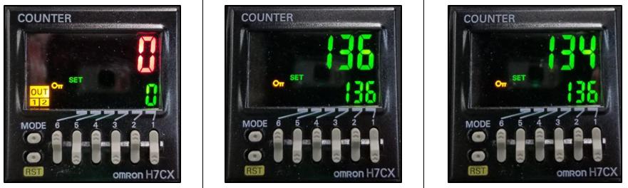
2. Thesmaller green numbersinthebottomrightsideofthecontroller displaythesetpoint.Thelarger white numbersinthecenterofthe controllerdisplaytheactualtemperatureofthematerialasreadby thethermocouplesinthePre-HeaterandTSUassembly.Seetheimage belowfortheOMRONHeaterControllerdisplay.
3. TurntheHeaterTemperatureSwitch(SeeFigure5onpage16)tothe right toturnONeachheater.
NOTE! TheTemperatureControllerdisplaystheactualmaterialtemperatureandtheset point.TheYELLOWboxwith thewordOUTindicatesthatthe heatersarebeingpowered.
WARNING! TheControllersarefactoryprogrammedandare notfieldre-programmable.Ifaproblemisencountered,contact yourPMCDistributor.Donotattempttochangeanyofthe programmedparameters.DonotsubstituteaControllerfrom analternatesupplierasitsusemayresultinequipmentdamage and/orbodilyinjury.
10 START-UP NOTE! Followtherecommendedprocedureintheordershown.
CAUTION! TheStart-upproceduresassumethatallstepsinProportionerpurginghavebeenperformedandnoproblemswere found.
1. Checkthehydraulicfluidlevelandserviceasrequired.
2. Makesurethematerialshavebeenstoredatthemanufacturer’srecommendedtemperature.Askyourmaterialsupplierforinformation(MaterialSafetyDataSheet)on theminimumstoragetemperature.
3. Y-Strainerscreensshouldbecheckedroutinely.
4. ConnectairsupplytothetwoTransferPumpsandensureAirValvesareinthefull OPENposition.OPENbothProportionerMaterialInletBallValves.
CAUTION! RemoveallHeatedHosesectionsfromcoiledstorage andlayflattoeliminateheatbuild-upandpossibleHeatedHose failure.
5. TurnONMainPower(SeeFigure5onpage16).
6. TurnONControlPower(SeeFigure5onpage16).
7. TurnONHoseHeater(SeeFigure5onpage16)andconfirmmaterialset-pointtemperatureasrecommendedbythematerialsupplierorapplicationconditions.
CAUTION! ToavoidexcessivepressureintheProportioner,wait fortheHoseHeatertoreachitsset-pointtemperaturebeforecontinuing.
8. TurnONeachPrimaryHeaterandconfirmmaterialset-pointtemperatureasrequired bythematerialsupplierorapplicationconditionshasbeenreached.
9. TurnONMotorPower(Seefigure5onpage16).
10. SetPumpSwitch(SeeFigure5onpage16)toNORMAL.OneoftheDirectional IndicatorLights(SeeFigure5onpage16)willilluminate,indicatingtheMetering Pumpdirection,andtheMeteringPumpShaftswillbegintomove.
NOTE! TheMaterialPressureGaugesshouldbeapproximately equalandremainconstantthroughouttheMeteringPumpcycle. Ifnot,refertoTroubleShootingsection.
NOTE! DirectionalIndicatorLightsmustindicateMeteringPump directionwhenPumpSwitchisintheNORMALposition.Ifnot, refertoTroubleShootingsection.
11a. UsingtheHydraulicPressureControl,adjusttotherequired stallpressure andcheck eachMaterialPressureGauge.
12a. AutoShutDownCounter- Ifthisfunctionisnotneeded,leaveitintheoff position. TosettheAutoShutDownCounter:
a. Turntheswitchtotheonposition,thegreenlightwillilluminate.
b. InsertthenumberofcyclesdesiredtodisablethePHmachinebypushinginonthe whitetrianglestosetthecyclecount.Pushinontheredbuttonuntilthedata isreplicatedonthetoprow,thetoprowwillcountdown.
Model PumpSize CyclesperGallon
PHX-2(3,000PSI) 61 55Cycles
c. Whenthecountercountsdowntozerothemachinewillstopandthepumpdirectionallightwillbeoff,pushinontheredbuttontoreset.
13a. ProceedwithInstallationandStart-upoftheSprayGunaspertheGunmanual.
Stallpressure: WhenmaterialsareatrecommendedapplicationtemperatureandMetering Pumpsarepressurizedbutnotmoving.Thispressureisnormally100–200psi(7-14Bar) greaterthanthedevelopedspraypressureasrecommendedbythematerialsupplier.
NOTE! DirectionalIndicatorLightsmustindicateMeteringPump directionwhenPumpSwitchisintheNORMALposition.Ifnot, refertoTroubleShootingsection.
11b. (SeeFigure5onpage16)- Ifthisfunctionisnotneeded,leaveitintheoff position. TosettheAutoShutDownCounter:
a. InputthenumberofcyclesdesiredtodisablethePFmachineontotheAutoShut DownCounterbypushinginonthegraybuttonstosettheCountdownValue.The bottomrowof green numbersidentifiesthesetpoint.Thetoprowofnumbers identifiesthenumberofcycleslefttocountdownandwillinitiallybecolored red beforetheCountdownValueisset.Eachbuttoncorrespondstoaspecificdigit. Forexample,inordertosettheAutoShutDownCountertoavalueof136asseen intheimagesbelow,pressButton1(6)times,Button2(3)timesandButton3 (1)time.Seetableonpage30forapproximatecyclesrequiredpergallonorliter.
b. Pressthegray“RST”buttononthebottomleftofthedisplaytosetthecountdown value.Thetoprowofnumberswillnowbecome green.TurnthePumpSwitch (SeeFigure5onpage16)to Normal.Thetoprowofnumberswillcountdown by1aftereachcycleofthePumpLineiscompleted.
c. AfterthePumpLinehascompletedthesetnumberofcycles,theCountdownValue willread“0”andchangecolorto red,thePumpLinewillstopintheRetract position,andthePumpSwitch/IndicatorLightwillnolongerilluminate.
d. Tomakethemachineoperationalagain,resettheCountdownValuebypressing the“RST”buttonwiththenextdesiredCountdownValueorbyshuttingoffthe AutoShutDownCounter.
12b. ProceedwithInstallationandStart-upoftheSprayGunaspertheGunmanual.
11 SHUT-DOWN 11.1 SHORT-TERM Followtheprocedurebelowfortemporaryshut-downs,suchas lunchbreaks:
1. SetPumpSwitch(SeeFigure5onpage16)totheOFFposition.
2. Turnboth“A”and“R”HeatersOFF.HoseHeatershouldremainON.Neverleave ProportionerONifunattended.
3. CLOSESprayGunManualValves.
CAUTION! ExcessiveforceopeningorclosingtheManualValves mayresultindamagetotheManualValvesand/orCouplingBlock.
11.2 LONG-TERM Followtheprocedurebelowforshut-downswhenworkis stoppedfortheday:
1. SetPumpSwitch(SeeFigure5onpage16)totheRETRACTposition.
2. SprayofftheapplicationsurfaceuntilMaterialPressureGauges(SeeFigure3onpage 14)readingsbegintofall.
CAUTION! ToavoidpossibleProportioningPumpSealweepage, andmoisturevapordriveintotheHeatedHoses,thesystempressureshouldnotbereducedtozero.Itisrecommendedtolower thesystempressuretoaminimumof400psi(28bar).
3. CLOSEtheSprayGunCouplingBlockManualValves.
4. TurnOFFMotorPower(SeeFigure5onpage16).
5. TurnOFFtheAandRHeatersandHoseHeater(SeeFigure5onpage16).
6. TurnOFFtheControlPower(SeeFigure5onpage16).
7. TurnOFFtheAutoShutDownSwitch(SeeFigure5onpage16).
8. TurnOFFtheMainPower(SeeFigure5onpage16).
9. DisconnecttheairsupplytothetwoTransferPumpsandCLOSEtheProportioner MaterialInletValves.
CAUTION! ExcessiveforceopeningorclosingtheManualValves mayresultindamagetotheManualValvesand/orCouplingBlock.
12 TROUBLESHOOTING ThisPHSeriesProportionerhasbeendesignedandbuilttowithstandsevereworkingconditionswithahighdegreeofreliability,providedthatitisusedinasuitableapplication byaproperlytrainedoperator.Thischaptercontainsinformationonpossiblefaultsthat mayinterrupttheoperationofthePHSeriesProportioner.Theinformationprovidedwill serveasaguidelinetodetectandresolveproblems.Inanycase,feelfreetocontactyour authorizedPMCdistributor,whereaqualifiedtechnicianwilladviseyou.
WARNING! Onlyqualifiedpersonnelshouldperformtroubleshooting;unqualifiedpersonnelmaycausedamagetotheunitandput theoperatoratrisk.
Topreventpossibleinjurycausedbyincorrecthandlingofthe rawmaterialsandsolventsusedintheprocess,carefullyreadthe MaterialSafetyDataSheet(MSDS)providedbyyoursupplier. Dealwiththewastecausedaccordingtocurrentregulations.
Toavoiddamagecausedbytheimpactofpressurizedfluids,do notopenanyconnectionorperformmaintenanceworkoncomponentssubjecttopressureuntilthepressurehasbeencompletely eliminated.
Usesuitableprotectionwhenoperating,maintainingorbeing presentintheareawheretheequipmentisfunctioning.Thisincludes,butisnotlimitedto,theuseofprotectivegoggles,gloves, shoesandsafetyclothingandbreathingequipment.
Theequipmentincludescomponentsthatreachhightemperatures andcancauseburns.Hotpartsoftheequipmentmustnotbe handledortoucheduntiltheyhavecooledcompletely.
Topreventseriousinjurythroughcrushingoramputation,do notworkwiththeequipmentwithoutthesafetyguardsinstalled onthemovingparts.Makesurethatallthesafetyguardsare correctlyreinstalledattheendoftherepairormaintenancework oftheequipment.
12.1 HEATERS WARNING! Onlyqualifiedpersonnelshouldperformtroubleshooting;unqualifiedpersonnelmaycausedamagetotheunit,personnel, orpropertyandputtheoperatoratrisk.TheHeatersarecomponentsthatreachhightemperatures;youmustwaituntiltheycool beforehandling.
NOTE! TheThermalLimitSwitchisasafetyswitchincontactwith theHeaterBody.Ifthesurfacetemperatureexceeds220◦ F(109◦ C) theLimitSwitchwillshutofftheHeaterpower.TheLimitSwitch willnotre-setuntilthetemperatureintheHeaterisbelow190◦F (88◦ C).Thesystemisdesignedthatincaseofanovertemperature, acontactorlocatedintheconsolewillopenanddisablepowerto bothHeatersandtheHose.
Followtherecommendedprocedureintheindicatedordertosolvetheproblemandavoid unnecessaryrepairs.MakesureallSwitchesareinthecorrectpositionandIndicatorLights ONbeforedeterminingtheexistenceofafault.
FrequentHeaterProblems Primaryheaterdoesnotheatandthedisplayonthecontrollershowsambienttemperature. Page35
Primaryheaterdoesnotheatandthedisplayonthecontrollershowsan errormessage(SbEr,EEPE,CjEr,AdEr). Page36
Primaryheatercontrollershowsexcessivetemperatureandthecircuithas turnedoff. Page36
PrimaryheaterTemperaturedropsexcessivelywhilespraying. Page37
• Problem: Primaryheaterdoesnotheatandthedisplayonthecontrollershows ambienttemperature.
Solutions:
1. Checkthatthelightontheon/offswitchislitwhentheheateristurnedon,if notreplacetheswitch.
Ifthelightison,movetothenextstep.
2. Checktheheaterbreakerinthemainconsoleandresetthebreaker.Ifitcontinues totrip,wrapanAmpClamparoundoneofthewirescomingoffthebreaker.If theAmperagereadingdoesnotexceedtheratingofthebreaker,thebreakerneeds tobereplaced.Ifthebreakerdrawsmorethanitsratingthemostlikelycauseis thatoneormoreofthefirerodslocatedintheheaterareshorted. Ifthebreakerisnottripped,moveontothenextstep.
3. Opentheconsoletopandlocatethesolidstaterelaysfortheheaters,lookingover theconsoletopfromthefrontofthemachine.Therearetworelaystotheleft bottomoftheconsole,theonetothefarleftisforthe“A”heaterandtheoneto therightisforthe“R”heater.Withtheheateron,looktoseeifanLEDlightis litontherelay.
IfthereisnoLEDlightonthesolidstaterelay,movetothenextstep.
4. WithaDCvoltmeterreadacrosspositionA1andA2onthesolidstaterelay (smallerwires)ifyouhaveareadingof4-6voltsDCandtheACreadingacross L1andL2(Heavywires)reads208-230voltsACreplacethesolidstaterelay. With4-6voltsDCatA1andA2theproperreadingshouldbe1voltACacross L1andL2.Adefectiveovertemperatureswitchwillopenacontactordisabling bothHeatersandtheHose.
IfthereisnoDCvoltagetotherelay,movetothenextstep.
5. ChecktheM1contactortoensureitisactivated.Ifnot,inspectthecontactorfor failure.
IftheM1contactorisactivated,movetothenextstep.
6. UsingaDCvoltmeter,onanEatonControllermeasureacrossposition5and9on thebackoftheheatercontroller.OnanOmronControllermeasureacrossposition 5and6onthebackoftheheatercontroller.Thisistheoutputofthecontroller andsendspowertothesolidstaterelay.OnanEatonController,yourreading willbe4-6voltsDC.OnanOmronController,yourreadingwillbe12voltsDC. Ifthereisnoreadingchecktomakesurethatthesettemperatureofthecontroller isabovetheactualtemperaturereadingonthecontroller.Beforereplacingthe controllerreadacrossposition1and2tomakesurethatthecontrollerispowered up,yourreadingwillbe208to230voltsAC.Ifthereisnovoltagedetected;check forloosewiresoramalfunctionoftheheatercircuitbreaker.
• Problem: Primaryheaterdoesnotheatandthedisplayonthecontrollershowsan errormessage(SbEr,EEPE,CjEr,AdEr).
Solutions:
1. Checkposition6and7ontheheatercontrollerforloosewires. Ifthewiresaretight,movetothenextstep.
2. Removetheheatercoverandcheckthatthethermocouplewiresaresecuretothe harnessgoinguptothecontroller. Iftherearenolooseconnectionsreplacetheheaterthermocouple.
• Problem: Primaryheatercontrollershowsexcessivetemperatureandthecircuithas turnedoff.
CAUTION! Theheatermustbeallowedtocooldownbefore continuing.
Solutions:
1. Setthecontrollersetpointatleast20degreeslowerthanthetemperatureshown onthecontroller.BrieflyturnontheheaterandlookfortheLEDlightonthe solidstaterelaytobeon. Ifthelightison,replacethecontroller. Ifthelightisoff,replacethesolidstaterelay.
• Problem: PrimaryheaterTemperaturedropsexcessivelywhilespraying.
Solutions:
1. Temperatureofthechemicalinthecontainersistoocold.
2. Exceedingtheflowratespecificationofthemachine.Useasmallermixingchambertoreduceflow.
3. Disconnectpowertothemachine. Oneormoreofthefirerodsintheheaterhave malfunctioned.Removetheheatercoveranddisconnectthewirestomeasurethe resistanceacrosseachrod.Installingasmallermixingchamberinthegunmay allowyoutosprayuntilanewrod(s)isinstalled.
CAUTION! Iftherodthatisusedinconjunctionwiththe thermocoupleisdefective,donotoperatetheheateruntilthe rodisreplaced.
IndividualOhmMeasurement
1250WATT 37OHMS
1500WATT 31OHMS
1750WATT 27OHMS
12.2 HYDRAULICDRIVESYSTEM FrequentHydraulicDriveSystemProblems HydraulicPumpdoesnotdeveloppressureandtheelectricmotorisnot running. Page38 HydraulicPumpdoesnotdeveloppressure. Page39 LoworzerohydraulicpressurewithunusualHydraulicPumpnoises. Page39
Followtherecommendedprocedureintheindicatedordertosolvetheproblemandavoid unnecessaryrepairs.MakesureallSwitchesareinthecorrectpositionandIndicatorLights ONbeforedeterminingtheexistenceofafault.
WARNING! Onlyqualifiedpersonnelshouldperformtroubleshooting;unqualifiedpersonnelmaycausedamagetothe unit,personnel,orpropertyandputtheoperatoratrisk. TheHeatersarecomponentsthatreachhightemperatures; youmustwaituntiltheycoolbeforehandling.
CAUTION! ExcessiveforceopeningorclosingtheManual ValvesmayresultindamagetotheManualValvesand/or CouplingBlock.
• Problem: HydraulicPumpdoesnotdeveloppressureandtheelectricmotorisnot running. Solutions:
MotorContactorSafetyorMotorBreaker- The ElectricMotorisprotectedfromexcessivecurrentbyan OverloadSafetySwitch.AfterallowingtheMotorto cool,opentheControlPanelandresetMotorContactor Safety.
• Problem: HydraulicPumpdoesnotdeveloppressure. Solutions:
NOTE! HydraulicpressureisnotgeneratediftheMotorPower Switch(SeeFigure5onpage16)isOFForthePumpSwitch(See Figure5onpage16)isintheOFFposition.
HydraulicPowerPackage- WiththePumpSwitchintheNORMALposition,the failureoftheHydraulicPumptodeveloppressureislossofpumpsuction(prime).To ensurepositiveprime,checkthefollowing:
a. MotorRotation.
b. HydraulicReservoirisfilledtothecorrectlevel.
c. HydraulicPumpCaseisfilledwiththeproperhydraulicfluid.
d. LooseInletPlumbing:CheckthatallinletplumbingtoHydraulicPumpistight ensuringnoairleakageintothehydraulicsystem.
• Problem: LoworzerohydraulicpressurewithunusualHydraulicPumpnoises.
Solutions:
1. Theuseofanincorrecthydraulicfluidcanresultisunusualnoisesfromthepump, excessivewear,andmoistureabsorption.Ensurethehydraulicoilusedisfrom thelistonpage56.Inaddition,continuousexcessivehydraulicoiltemperature aswellasfailuretochangethehydraulicoilonayearlybasiswillcausetheoilto failandresultinexcessiveHydraulicPumpwearandunusualnoises.
2. LooseInletPlumbing:CheckthatallinletplumbingtoHydraulicPumpistight, ensuringnoairleakageintothehydraulicsystem.
12.3 METERINGPUMP-LINE Figure10:MeteringPump-Line(PL-1A/PL-2)
FrequentPump-LineProblems Meteringpumpsdonotchangedirectionandthepressuresonbothof chemicalgaugesarelowerthannormal.
Page40
Cavitation. Page43
PressureLoss:Discharge/InletBall. Page43
Followtherecommendedprocedureintheindicatedordertosolvetheproblemandavoid unnecessaryrepairs.MakesureallSwitchesareinthecorrectpositionandIndicatorLights ONbeforedeterminingtheexistenceofafault.
• Problem: Meteringpumpsdonotchangedirectionandthepressuresonbothof chemicalgaugesarelowerthannormal.
Solutions:
1. TheMeteringPumpLinehasReversingPlateswhichactuatestwoProximity Switches(EL-153),oneateachendofthestroke.TheProxSwitchesinturn actuatetheappropriateDirectionalValveSolenoid(HI-05003).Failuretomake contactwitheitherProxSwitchmaybecausedby:
a. DeformationoftheReversingPlate.
b. ForeignmaterialpreventingtheReversingPlatefromcontactingtheProx Switches.
2. PassingoftheReversingPlatebeyondtheProxSwitchmaybecausedby:
a. FailureoftheProxSwitchandrelatedcomponentsonthesideoftheover-run.
b. FailureofacomponentoftheDirectionalValve.
c. MountingPlateand/orProxSwitchisoutofadjustment.
NOTE! IFTHEDIRECTIONALINDICATORLIGHT(Q,Page 16)ISONCHECKTHEREVERSINGVALVECOILONTHE SIDETHATTHELIGHTISON.IFYOUHAVE24VOLTSDC ATTHEPLUGCHECKTHEOHM’SRESISTANCEOFTHE COIL,ITSHOULDREADAPPROXIMATELY19OHM’s,IF NOTREPLACETHECOILORREVERSINGVALVE.IFTHE DIRECTIONALLIGHTISOFFPROCEEDBELOW.
NOTE! BEFORETROUBLESHOOTING,THEREVERSING PLATEMUSTBEMOVEDAWAYFROMTHESWITCH.
d. Bleeddownthechemicalpressures.
e. EnsurePumpSwitch(P,section5)is OFF
f. Turnonthemotor(X,section5).
g. GototheDirectionalValveandlocatetheActuationCoils.Locatedinthe middleofeachcoilisasmallroundtabthatcanbepushedintomanually shiftthespooltomovethepumps.IftheReversingplateisallthewayto theleftpushinontherightsidecoil.Ifit’sallthewaytotherightside,push inontheleftsidecoil.
WARNING! THEMOTORMUSTBEOFFANDTHEPUMP SWITCHINTHENORMALPOSITION.
h. Takeasmallscrewdriverorathinpieceofmetalandmoveitacrossthefront ofeachProxswitch.Aredlightonthebackoftheswitchshouldilluminate. Ifnot,replacetheswitchthatdoesnotlight.
i. IftheProxswitcheslightup,turnoffallpowerandcheckforcontinuityon bothoverpressureswitches,pin1and2.Ifthepressureswitchesaregood, gotothetwosolidstaterelaysinsidetheconsoleandinterchangethem,they canbepulledfromtheirhousing.Poweruptheunitwiththepumpswitch inthenormalpositionandthemotor OFF.Ifthedirectionallightcomeson replacethedefectivesolidstaterelay.IfnotreplacetheLatchingrelay.
3. SafetyPressureSwitch-EachMeteringPumphasaSafetyPressureSwitchsetto 2,200psi.for#123pumps,3,200psifor#61pumps.Whenthematerialsystem reachesthispressure,theSafetyPressureSwitchwillremovepowerfromthe DirectionalValveandDirectionIndicatorLights(Q,section5).LackofDirection IndicatorLightsalongwithhighpressureindicatedononeorbothofthematerial PressureGauges(E,F,section5)isanindicationofanover-pressurecondition. TheSafetyPressureSwitchesareamomentarydesign;whenthepressurebleeds offtheMeteringPumpLinewillresumenormaloperation.However,thecauseof theover-pressureshouldbedeterminedandcorrected.Themostcommoncauses are:
a. CavitationsoftheMeteringPumponthe low pressuresidecausinghigh pressureontheoppositeside.
b. ArestrictionintheSprayGunonthe high pressureside.
4. Pressure/MaterialImbalance-Troubleshootingthisproblemrequirestheapplicatorto:
a. KnowwhattheNORMALspraypressuresarefortheapplicationinprogress.
b. DeterminewhatmaterialisNOTexitingtheMixingChamber.
c. ReadthePressureGaugeontheproblemsideandinterpretthereading.
MaterialCondition ”A”GAUGE ”R”GAUGE • Problem: Cavitation.
Solutions:
1. CavitationsoccurwhentheMeteringPump(BorC,section5)requiresalarger volumeofmaterialthanthesupplysystem(TransferPump)canfurnish.This createsa”void”ofmaterialintheMeteringPump.Themostcommoncausesof cavitationsare:
a. Materialtemperaturetoolowcausingincreasedmaterialviscosityresulting intheinabilityoftheTransferPumptomaintainsufficientsupplytothe MeteringPump.Thisismostcommonwithtoday’sblowingagents.Ensure thematerialtemperatureinthedrumsisnolowerthanthematerialsuppliers’ recommendation.
b. FailuretoventthematerialdrumwhiledrawingmaterialoutwiththeTransferPumpcausesavacuumandcavitationsintheTransferPump.Ensurethe drumisventedtotheatmosphereoraDesiccatedAirDyerKitisinstalled asrecommendedbythematerialsupplier.
c. InsufficientairvolumeforTransferPumporapartiallyclosedTransferPump AirValvewilllimittheabilityoftheTransferPumptooperateatitsmaximumcapability.
d. InletMaterialScreen(M,section5)obstructed(SeeMAINTENANCEsection,page48).
e. MeteringPumpInletBalldoesnotseatproperlyallowingmaterialtoflow backintotheMaterialDeliveryHosewhentheMeteringPumpisonthe ”Discharge”stroke.ThiscausesthevolumeofmaterialonthatMetering Pumptobelessonthedischargestrokeresultinginintermittentoff-ratio materialandPressureGaugefluctuation.
• Problem: PressureLoss:Discharge/InletBall.
Solutions:
1. SimultaneousobservationofthematerialPressureGauge(E,F,section5)and DirectionIndicatorLight(Q,section5)isnecessarytodeterminewhichdirection theMeteringPumpfailstomaintainpressure.Refertothecharttodetermine problem:
LeftArrowDirectional IndicatorLightON
RightArrowDirectional IndicatorLightON
IsoPressureGauge FALLS
PolyPressureGauge FALLS
IsoInletBalldoesnotseat properly
PolyDischargeBalldoesnot seatproperly
IsoDischargeBalldoesnot seatproperly
PolyInletBalldoesnotseat properly
InmostcasesthecauseofaleakingInlet/DischargeBallisforeignmaterialpreventing theBallfromseatingproperly.Iftheabovestepsdonotresolvetheproblem,replacethe appropriateBall.ForserviceseeMAINTENANCE:METERINGPUMP-LINE(page52).
12.4 HOSEHEATING WARNING! Beforecorrectinganykindofdefect,makesurethe MainPowerSwitchisOFFandincomingpowerislockedOFF. NEVERaccesstheinsideoftheControlPanelwiththeProportionerpowersupplyON.TheHeatedHosearecomponentswhich reachhightemperatures;youmustwaituntiltheyhavecooledbeforehandling.
CAUTION! ExcessiveforceopeningorclosingtheManualValves mayresultindamagetotheManualValvesand/orCouplingBlock.
HoseHeatingProblems HeatedHosedoesnotheatandthedisplayonthecontrollershowsambient temperature. Page44
Hosedoesnotheatandthedisplayonthecontrollershowsanerrormessage (SbEr). Page45
Heatedhosecontrollershowsexcessivetemperature. Page46
Hosewillheatbutdoesnotcomeuptosettemperature. Page46
Hosedoesnotheatandthedisplayonthecontrollershowsanerrormessage. Page46
Followtherecommendedprocedureintheindicatedordertosolvetheproblemandavoid unnecessaryrepairs.MakesureallSwitchesareinthecorrectpositionandIndicatorLights ONbeforedeterminingtheexistenceofafault.
• Problem: HeatedHosedoesnotheatandthedisplayonthecontrollershowsambient temperature.
Solutions:
1. Checkthatthelightontheon/offswitchislitwhentheheateristurnedon,if notreplacetheswitch.
Ifthelightison,moveontothenextstep.
2. ChecktheHoseHeatbreakerinthemainconsoleandresetthebreaker.Ifit continuestotrip,wrapanAmpClamparoundoneofthewirescomingoffthe breaker.Ifitdoesnotdrawmorethantheratedvalueofthebreaker,thebreaker needstobereplaced.
Ifthebreakerisnottripped,moveontothenextstep.
3. Checkthecircuitbreakermountedonthetransformerandresetthebreaker. Ifitcontinuestotrip,wrapanAmpClamparoundoneofthewiresfromthe transformergoingtotheheatedhose.Ifitdoesnotdrawmorethantherated valueofthebreaker,thebreakerneedstobereplaced.
IftheAmpDrawislessthantheratedvalue,moveontothenextstep.
4. Checkthatthetapsettingonthetransformerissetfortheproperhoselength. Ifitissetcorrectly,movetothenextstep.
5. Tocheckthesecondarysideofthetransformer,youmusttakeanACvoltreading acrossthetwoleadscomingoutofthetransformerthatareconnectedtothe “A”and“R”hoseleads.Ifyouarereadingvoltage(yourvoltreadingwillvary dependingonwhattapsettingisused),mostlikelytheproblemisintheheated hose.Eitheraconnectorhascomelooseorthereisabrokenwire.
6. Becausethegunwhiptakesthemostabuse,itismostlikelythewhipthathas failed.Disconnectthecrossoverwiresonthemachineendofthewhiphoseand connectthetwowirestogethercomingoffthe50’section.Turnonthehoseheat andseeifthehoseheatcircuitisoperating;ifsoreplacethewhip.Totakea continuityreadingthroughtheheatedhose,oneoftheleadsfromthetransformer tothe“A”or“R”heatedhosemustbedisconnected. Ifnovoltageiscomingoutofthetransformertotheheatedhose,move ontothenextstep.
7. Opentherightsideofthetank(wherethetransformerislocated)andlocatethe solidstaterelayforthehosecircuit(EL-35).Withthehoseturnedonandthe LEDlightilluminatedontherelay,takeavoltmeter(setonDC)andmeasure acrosspositionA1andA2;yourreadingshouldbe24volts.ThentakeanACvolts measurementacrosspositionL1andL2(heavywires).Withtherelayfunctioning properlyyoushouldhavea1voltReading.IftheReadingis18to90voltsAC, therelayhasmalfunctionedandneedstobereplaced.IftheACReadingacross L1andL2is.025voltschecktheovertemperatureswitchesintheheaters.A defectiveovertemperatureswitchwillopenacontactordisablingbothHeaters andtheHose.
Ifthereisnolightonthesolidstaterelay,movetothenextstep.
8. UsingaDCvoltmeter,measureacrossposition5and6onthebackofthehose controller.Thisistheoutputofthecontrollerandsendspowertothesolidstate relay.Yourreadingwillbe 4-6voltsDC.Ifthereisnovoltage,checktomake surethatthesettemperatureofthecontrollerisaboveambienttemperature. Beforereplacingthecontroller,readacrossposition1and2tomakesurethatthe controllerispoweredup;yourreadingwillbe208to230voltsAC. IfthereisnoDCvoltagetotherelay,movetothenextstep.
• Problem: Hosedoesnotheatandthedisplayonthecontrollershowsanerrormessage (SbEr).
Solutions:
1. Checkposition6and7ontheheatercontrollerforloosewires. Ifthewiresaretight,movetothenextstep.
2. Removethetransformercoverandcheckthatthethermocouplewiresaresecure totheharnessgoinguptothecontroller.Iftherearenolooseconnections,disconnectthewirefromtheTSUandconnectitdirectlytothethermocoupleharness
comingoutofthehosetransformer.
Ifthecontrollerstillshowstheerrorcode,replacethehosethermocouple.Iftheerrorcodegoesawayandtemperatureisnowshownon thedisplayofthecontroller,thenalltheTSUharnessesfromtheTSU tothetransformerneedtobecheckedforlooseconnectorsoroneor moreoftheharnessesaredefective.
• Problem: Heatedhosecontrollershowsexcessivetemperature.
Solutions:
1. Setthecontrollersetpointatleast20degreeslowerthanthetemperatureshown onthecontroller.Brieflyturnonthehoseandlookfortheledlightonthesolid staterelaytobeon.
Ifthelightison,replacethecontroller. Ifthelightisoff,replacethesolidstaterelay.
• Problem: Hosewillheatbutdoesnotcomeuptosettemperature.
Solutions:
1. Checkthetapsettingonthetransformertoensurethatthecorrectpositionhas beenselectedforthelengthofhosebeingused.Dependingonthemachines incomingvoltage,youmayhavetomovethetapsettinghigher(upone).
CAUTION! Donotexceedthetripvalueofthetransformerhose breaker.
WARNING! Beforecorrectinganykindofdefect,makesurethe MainPowerSwitchisOFFandincomingpowerislockedOFF. NEVERaccesstheinsideoftheControlPanelwiththeProportionerpowersupplyON.
• Problem: Hosedoesnotheatandthedisplayonthecontrollershowsanerrormessage.
Solutions:
1. Checkposition9and10ontheheatercontrollerforloosewires. Ifthewiresaretight,movetothenextstep.
2. Removethetransformercoverandcheckthatthethermocouplewiresaresecure totheharnessgoinguptothecontroller.IftherearenolooseconnectionsdisconnectthewirefromtheTSUandconnectitdirectlytothethermocoupleharness comingoutofthehosetransformer.
Ifthecontrollerstillshowstheerrorcode,replacethehosethermocouple.
Iftheerrorcodegoesawayandtemperatureisnowshownonthedisplayofthecontroller,thenalltheTSUharnessesfromtheTSUtothe transformerneedtobecheckedforlooseconnectorsoroneormoreof theharnessesaredefective.
12.5 PRESSUREBALANCECONTROL IfthePressureBalanceControlboxisnotworkingproperly,followthesestepstoresolvethe potentialissue:
1. WiththeMainPower ON,checkthePower/RunlightontheControlUnit:
a. IfOFF,theControlUnitisnotgettingpower.Checkforlooseorpoorwire connections.IfthePower/Runlightstilldoesnotturnon,contactyourauthorized PMCdistributor.
b. If SOLID,theControlUnithaspowerbutnoprogram.Contactyourauthorized PMCdistributor.
c. If BLINKING,theControlUnithaspowerandisprogrammedproperly.Proceedtothenextstep.
2. WithMainPower ON,turntheRotarySwitchtoaPressureDifferentialNumberand checktheAmberlightonCR1:
a. If OFF,CR1isnotactivatingproperly.Checkforlooseorpoorwireconnections betweentheControlUnitandCR1.
b. If ON,CR1isactivating,butthemechanicalswitchinsidetherelaymaynotbe functioningproperly.Ifthesystemhasfaulted(i.e.apressureimbalanceexists, theONlightturnsoff,andtheFAULTlightturnson),butthepumpsdonotshut off,checkforcontinuitybetweencontacts11and12onCR1.Ifthereiscontinuity, contactyourauthorizedPMCdistributor.Ifthereisdiscontinuity,proceedtothe nextstep.
3. ContactyourauthorizedPMCdistributorforfurtherassistance.
13 MAINTENANCE ToachievemaximumoutputfromthePHSeriesProportioner,adailyorregularmaintenancescheduleisrequired.
Topreventpossibleinjurycausedbyincorrecthandlingofthe rawmaterialsandsolventsusedintheprocess,carefullyreadthe MaterialSafetyDataSheet(MSDS)providedbyyoursupplier. Dealwiththewastecausedaccordingtocurrentregulations.
Disconnecttheunitfromthepowersupplybeforecarryingout anyoperationinsidetheelectricalconsole.Theelectricalmaintenanceofthemachinemustonlybeperformedbyaqualified electrician.
Toavoiddamagecausedbytheimpactofpressurizedfluids,do notopenanyconnectionorperformmaintenanceworkoncomponentssubjecttopressureuntilthepressurehasbeencompletely eliminated.
Usesuitableprotectionwhenoperating,maintainingorbeing presentintheareawheretheequipmentisfunctioning.Thisincludes,butisnotlimitedto,theuseofprotectivegoggles,gloves, shoesandsafetyclothingandbreathingequipment.
Theequipmentincludescomponentsthatreachhightemperatures andcancauseburns.Hotpartsoftheequipmentmustnotbe handledortoucheduntiltheyhavecooledcompletely.
Topreventseriousinjurythroughcrushingoramputation,do notworkwiththeequipmentwithoutthesafetyguardsinstalled onthemovingparts.Makesurethatallthesafetyguardsare correctlyreinstalledattheendoftherepairormaintenancework oftheequipment.
CAUTION! Allrepairsperformedbyunqualifiedpersonnelor theuseofpartsotherthansuppliedbyPMCmaycausedamage totheunitandputtheoperatoratrisk.
13.1 INLETMATERIALSCREENS InspectionoftheInletMaterialScreensonadailybasisisnolongernecessaryaslongasthe followingconditionsaremet.
1. Materialdrumsarestoredwithintherecommendedmaterialstoragetemperaturerange anddrumsarenotopenedpriortoinstallingtheProportionerMaterialTransferPumps.
2. Desiccantairdryersareusedtodryreplacementairasmaterialisremovedfromthe drumstotheProportioner.
3. Consolidationofoldmaterialintoacommondrumforuseisminimized,especiallythe Iso(A).
Iftheaboveconditionsaremet,inspectionoftheInletMaterialScreensmaybedoneona bi-weekly basis.
NOTE! InspectandcleanInletMaterialScreensbeforeProportionerstart-up.Theyshouldnotbecleanedafterthedays’ operationastheProportionershouldbepurged(seepage24) immediatelyafterinspectionandcleaning.Thisistoreduce theriskofmoisturecontamination,contaminationthrough thereactionwiththesolventusedinthecleaningoperation, andcross-overattheSprayGunduetoairentrapment.
CAUTION! MakesuretheMainPowerSwitchisOFFand incomingpowerislockedOFF.
1. CLOSEthePoly(R)ProportionerInletValve.
2. PlaceasuitablecontainerundertheMaterialInletStrainertocollecttheresidual material.CarefullyloosentheStrainerPlugtodrainmaterialintothecontainer.
3. CompletelyunscrewtheStrainerPlug.
4. RemovetheSeal,SpringandScreenandcleanthemwithasuitablesolvent.Drythe partsandensuretheScreenisnotobstructed.ReplacetheScreenifmorethan20% oftheScreensurfaceisobstructedbyresidue.
5. ReinstalltheScreen,SpringandSeal.ScrewontheStrainerScrewandscrewinPlug.
6. OPENthePoly(R)ProportionerInletValve,pressurizetheMaterialTransferPump, checkforleaksandwipeY-strainerclean.
7. RepeatabovefortheIso(A)side.
8. ProceedwithProportionerPurgingoperation(Seepage24).
13.2 ISOLUBRICATIONSYSTEM DAILY: ChecktheconditionofthePMCLubeOilintheIsoLubeReservoir. ReplacethePMCLubeOilifyouseesignificantchangesinthecolororsignsof solidification.EnsureinsideofReservoiriswipedclean.
ToreplacetheLubeOil,proceedasfollows:
1. RemovetheLubeReservoirfromitssupport,unscrewtheLidandremovetheCheck ValvefromtheSuctionHose.
2. EmptythecontaminatedLubeOilinawastecontainerandrefittheCheckValvein theSuctionHose.
NOTE! Valveisdirectional.
3. CleantheReservoir,refillwithLubeOil,andscrewontheLidandplacetheReservoir initssupport.
Thesystemisauto-suctionanddoesnotneedpriming.
13.3 HYDRAULICDRIVESYSTEM WARNING! Beforeperforminganymaintenance,makesurethe MainPowerSwitchisOFFandincomingpowerislockedOFF. TheHydraulicUnitisacomponentthatworksunderpressure.Do notopenanyconnectionorcarryoutmaintenanceoncomponents subjecttopressureuntilallpressurehasbeenbledtozero.
Thehydraulicunitshouldbeservicedyearly:
1. CompletelydraintheTankofhydraulicfluid.
2. CleantheTankToptopreventforeignmaterialfromfallingintotheTankwhenthe Coverisremoved.
3. UnscrewtheSuctionPipefromitsconnectionwiththeHydraulicPump.
4. RemovetheCoverandSuctionPipefromtheHydraulicTank.Takecarenottodamage TankCoverGasket.
5. InspectthebottomoftheTankforsedimentandcleanasrequired.CleantheSuction Pipeanditsconnections.
6. FilltheTankwith10gal(37L)ofapprovedhydraulicfluid(Seepage56forrecommendations).
7. InserttheSuctionPipeintotheTankCoverandinstalltheCover.Again,takecarenot todamageTankCoverGasket.ConnecttheSuctionPipesecurelytotheHydraulic Pump.
8. EnsuretheHydraulicPumpCaseisfulloffluidandproceedwiththenormaloperation.
13.4 METERINGPUMP-LINE WARNING! Beforeperforminganymaintenance,makesurethe MainPowerSwitchisOFFandincomingpowerislockedOFF.Allowmaterialtemperaturetocoolbelow80◦ Fandbleedallmaterial pressuretozero.
Weekly: WhentheProportioningPumpsarefunctioningproperlyitisnotunusualfora smallamountofPoly(R)materialtoappearonthePumpShaft.Thismaterialshouldbe wipedawaysodirtdoesnotaccumulateonthePumpShaftandthePumpShaftPackings arenotdamaged.
Yearlyorasrequired: ItisnotunusualforthosewhousethePHSeriesProportioneron aregularbasistorebuildtheProportioningPumpsonayearlybasisandservicetheHydraulicDriveSystem(Seepage51)atthesametime,whiletheProportionerisoutofservice.
13.5 PUMPBASESERVICE 1. CLOSEappropriateProportionerInletMaterialSupplyValveandremoveAirLine fromtransferpump.
2. EnsureallmaterialpressureintheProportionersystemiszeroandremoveappropriate RetainerNut.
3. ForInletBall:
• RemoveInletBallwithamagnet(DONOTuseanysharpobject),cleanBalland BallSeat,andinspectforforeignmaterialandanydamageontheInletBall.
• UsingsuppliedBallSeatTool(TL-02),checkforproperBallSeatGasketcompression.SnugSeatupto1/4turnmaximum110ft-lbs(149Nm).
4. ForDischargeBall:
• RemoveCageandSpring.
• RemoveDischargeBallwithamagnet(DONOTuseanysharpobject),cleanBall andBallSeat,andinspectforforeignmaterialandanydamageontheDischarge Ball.
• UsingsuppliedBallSeatTool(TL-02),checkforproperBallSeatGasketcompression.SnugSeatupto1/4turnmaximum30ft-lbs(41Nm).
13.6 PUMPSEALREPLACEMENT NOTE! RefertoPartsIdentificationforreference.
• WhentheIso(A)ProportioningPumpCylinderisdisassembledforservice,allparts includedinthePumpRebuildKit(KT-07000,KT-07002,KT-07004,KT-07006)should bereplaced.
• WhenthePoly(R)ProportioningPumpCylinderisdisassembledforservice,allparts includedinthePumpRebuildKit(KT-07001,KT-07003,KT-07005,KT-07007)should bereplaced.
• WhenassemblingProportioningPumplubricateallSeals,PistonRodandPumpCylinderwith#1LithiumGreasetoassistinassemblyandminimizeSealdamageduring re-assembly.
• WhenthePumpLineEndBlockisdisassembledforservice,allO-ringsincludedin theO-ringKit(KT-05009)shouldbereplaced.
• AfterreassemblyoftheProportioningPumpstorquetheAssemblyBoltsto30ft-lbs (41Nm).
CAUTION! Usewoodenorplastictoolsorabrassbrushforcleaning.Donotusemetalorabrasivetoolsthatcanscratchthecontact surfaces.
13.7 METERINGPUMPREMOVAL NOTE! WhenremovingthePolysidepump,skipsteps3and4.
1. Putmachineinretractposition.
2. Turnoffmainpoweranddischargeallpressuregaugestozero.
3. DisconnectthebottomelbowontheIsolubecylinderanddrainallIsolube.
4. DisconnectthetophosegoingtoIsolubecylinderthenuninstallredplug.
5. Removeclevispin.
6. Disconnectthehoseonthepumpflange.
7. DisconnecttheY-strainerfromelbow.
8. Carefullyremovethefourboltsandwasherswhileholdingthepumpinplace.
13.8 MATERIALHEATER WARNING! Beforeperforminganymaintenance,makesurethe MainPowerSwitchisOFFandincomingpowerislockedOFF. NEVERaccesstheinsideoftheControlPanelwiththeProportionerpowersupplyON.TheHeatersarecomponentsthatreach hightemperatures;youmustwaituntiltheyhavecooledbefore handlingandbleedallmaterialpressuretozero.
13.8.1 THERMOCOUPLEREPLACEMENT NOTE! TheThermocoupleisassembledintotheConnectorBody withaFerruleandNut.OnceinsertedintotheBodyandtheNut istightened,theFerrulelockstotheThermocoupleanddoesnot allowittoberelocatedormoved.ThelocationoftheThermocoupleisveryimportantandmustbedonecorrectlybeforetightening theNut.
1. UnscrewtheNutthatholdsthedefectiveThermocoupleandremovefromtheBody. DisconnectThermocouplewiringlocatedundertheTopCoveroftheHeater.Remove Bodyanddiscard.
2. InstallHeatingElementandSpringifalsoremoved.
3. InstallConnectorBodyintoHeaterusinganopen-endwrenchandtightentoprevent leakage.TeflonTapeorappropriateThreadSealantshouldbeused.
4. SlidetheNutandtheFerruleovertheThermocoupleandinsertthisassemblyinto theConnectorBodyuntilitcomesinto positivephysicalcontact withtheHeating Rod.MakesuretheSpringdoesnotpreventtheThermocouplefrommakingcontact withtheHeatingRod.
5. SlowlytightentheNutusinganopen-endwrench,ensuringtheThermocouplemaintainspositivephysicalcontactwiththeHeatingRod.
6. ReinstalltheThermocouplewires.
WARNING! Beforeperforminganymaintenance,makesurethe MainPowerSwitchisOFFandincomingpowerislockedOFF. NEVERaccesstheinsideoftheControlPanelwiththeProportionerpowersupplyON.TheHeatersarecomponentsthatreach hightemperatures;youmustwaituntiltheyhavecooledbefore handlingandbleedallmaterialpressuretozero.
ToreplaceadefectHeatingRod,proceedasfollows:
1. EnsureMainPowerSwitchisOFFandincomingpowerislockedOFF.Depressurize proportionerandremovetheCoveronHeater.
WARNING! IftheHeatingRodtobereplacedistheonein contactwiththeThermocouple,itisnecessarytoremovethe Thermocouplefirst.DonotloosenortightenThermocouple Body.
2. DisconnectthesuspectHeatingRodfromthewireconnectionsandtesttheHeating Rodagainforproperelectricalresistance.
3. UnscrewtheHeatingRodandremovefromtheHeaterBlockalongwithitsSpringand inspect;itmustbesmoothandshinyinappearance.Ifitisblackenedorhasmaterial adheredtoitreplacetheHeatingRod,evenifohmreadingisacceptable.
4. ApplyTeflonTapeorappropriateThreadSealanttotheHeatingRodthreadand assembleHeatingRodandSpringintotheHeaterBlock.Tightensecurelyto110 ft/lbs(150Nm).
5. Ifnecessarycarefullyre-installThermocoupleensuringpositivephysicalcontactwith theHeatingRod.MakesuretheSpringdoesnotpreventtheThermocouplefrom makingcontactwiththeHeatingRod.TightenNutwithopen-endwrench.
6. ReconnectwireconnectionsandreplaceCover.
7. EnsureHeaterisfullofmaterialpriortoelectricaltesting.
14 HYDRAULICOILSPECIFICATIONS RecommendedHydraulicOilSpecification: ISO/ASTMViscosityGrade32 Viscosity: 28.8–35.2SSUat104◦ FRustandOxidationInhibited
14.1 MANUFACTURERS • MobilDTE24(Recommended)
• Cook’sAlbavis8
• Ashland-ValvolineAW15
• Shell–Tellus32(25)
• SunOil-Sunvis706
• ChevronISO32
• AmericanOil&Supply–PQIso32
• GulfOil–Harmony32AW(43AW)
• AtlanticRichfield–DuroAWS-150
• BPOil–EnergolHLP-C32
• Exxon–NutoH-32(44)
• Margolis–T.I.P.100-15-7
• FiskeBros.–LubriplateHyd.#0
• SW–AlemiteHydraulicHD#0
• Texaco–RandoHD32(HDA0)
• White&Bagley–EPHyd.150
Figure13:HydraulicCylinderAssembly(HI-05025A)
1 1 -
2 1
3 2
2
5 2 - HYDRAULICSEALASSEMBLY(SEEPAGE57)
6 2
7 4
8 7
9 1
Figure14:CompleteHydraulicCylinderAssembly(HI-01)
1
15.5 ”R”PUMPASSEMBLY Figure15:”R”PumpAssembly(PU-05002-XXX)
1
”R”PUMPASSEMBLY 4 1 HI-05016 3/4NPTMX3/4NPTFSW
5 1 HI-05038 1/4NPTX9/16-18JIC90DEG
6 2 HI-05067 PIPEPLUG1/4-18,7/8TAPER
7 2 OR-00011A O-RING-014,CROSSOVERTUBE
8 2 OR-00046A O-RING-133,VITON,90D
14
15
1 PU-03013
1 PU-03012
1 PU-03011
16*
17
SHAFTBEARING,40PUMP,RSIDE
SHAFTBEARING,60PUMP,RSIDE
SHAFTBEARING,80PUMP,RSIDE
1 PU-03010 SHAFTBEARING,120PUMP,RSIDE
1 PU-05011-40 PUMPSHAFTASSY,40PUMP
1 PU-05011-60 PUMPSHAFTASSY,60PUMP
1 PU-05011-80 PUMPSHAFTASSY,80PUMP
1 PU-05011 PUMPSHAFTASSY,120PUMP
1 PU-05012-40 CYLINDER,40PUMP
1 PU-05012-60 CYLINDER,60PUMP
1 PU-05012-80 CYLINDER,80PUMP
1 PU-05012 CYLINDER,120PUMP
1 PU-05014-40 FLANGE,40PUMP
1 PU-05014-60 FLANGE,60PUMP
1 PU-05014-80 FLANGE,80PUMP
1 PU-05014 FLANGE,120PUMP
18 1 PU-05017 CROSSOVERTUBE
19 1 PU-05018 PUMPBASE
20 1 PU-05019 SEAT,INLET
21 1 PU-05020 BALL,INLET
22 1 PU-05021 SPRING
23 1 PU-05023-1 GASKET,PUMPRETAINERNUT
24 1 PU-05024 SEAT,DISCHARGE
25 1 PU-05025 BALL,DISCHARGE
26 4
27 4
28 4
NUT 29 1 PU-05029-40 PIN,40PUMP 1 PU-05029-60 PIN,60PUMP 1 PU-05029-80 PIN,80PUMP 1 PU-05029 PIN,120PUMP 30 1 PU-05030-40 SNAPRING,40PUMP 1 PU-05030-60 SNAPRING,60PUMP
1 PU-05030-80 SNAPRING,80PUMP 1 PU-05030 SNAPRING,120PUMP 31 1 PU-05031-40 CLEVIS,PISTON,40PUMP
1 PU-05031-60 CLEVIS,PISTON,60PUMP
1 PU-05031-80 CLEVIS,PISTON,80PUMP
1 PU-05031 CLEVIS,PISTON,120PUMP 32 1 PU-05032-40 FLANGE,PACKINGRETAINER,40PUMP
1 PU-05032-60 FLANGE,PACKINGRETAINER,60PUMP
1 PU-05032-80 FLANGE,PACKINGRETAINER,80PUMP 1 PU-05032 FLANGE,PACKINGRETAINER,120PUMP
33 1 PU-05044 BEARING,PISTON,40PUMP
1 PU-05043 BEARING,PISTON,60PUMP
1 PU-05042 BEARING,PISTON,80PUMP
1 PU-05041 BEARING,PISTON,120PUMP
34 1 TN-04186 GREASEFITTING
15.5.1 ”R”PUMPREBUILDKITS 40”R”PUMPREBUILDKIT(KT-07007)
QTY PARTNUMBER DESCRIPTION
1 KT-01016A-004 PISTONSEAL,40PUMP
2 OR-00011A O-RING,12X12MMID
2 OR-00046A O-RING-133,VITON,90D
1 OR-00051B O-RING-218,AFLAS,80D
1 PU-01013A GASKET,CYLINDERFLANGE
1 PU-05029-40 PIN,40PUMP
1 PU-03013 SHAFTBEARING,40PUMP
1 PU-05044 PISTONBEARING,40PUMP
1 PU-03003 TRIPLELIPSEAL,40PUMP
1 PU-03023 BULLET,40PUMP
2 TN-04199 SHCS,3/8-24X2.50
2 OR-00045A O-RING-028,VITON,90D
1 PU-01003-IG GASKET,DISCHARGEBALLSEAT
1 PU-01003-DG GASKET,INLETBALLSEAT
1 PU-05023-1 GASKET,PUMPRETAINERNUT
60”R”PUMPREBUILDKIT(KT-07005)
QTY PARTNUMBER DESCRIPTION
1 PU-01016A-006 PISTONSEAL,60PUMP
2 OR-00011A O-RING,12X12MMID
2 OR-00046A O-RING-133,VITON,90D
1 OR-00051B O-RING-218,AFLAS,80D
1 PU-01013A GASKET,CYLINDERFLANGE
1 PU-05029-60 PIN,60PUMP
1 PU-03012 SHAFTBEARING,60PUMP
1 PU-05043 PISTONBEARING,60PUMP
1 PU-03002 TRIPLELIPSEAL,60PUMP
1 PU-03022 BULLET,60PUMP
2 TN-04199 SHCS,3/8-24X2.50
2 OR-00045A O-RING-028,VITON,90D
80”R”PUMPREBUILDKIT(KT-07003)
QTY PARTNUMBER DESCRIPTION
1 PU-01016A-008
PISTONSEAL,80PUMP
2 OR-00011A O-RING,12X12MMID
2 OR-00046A
1 OR-00051B
O-RING-133,VITON,90D
O-RING-218,AFLAS,80D
1 PU-01013A GASKET,CYLINDERFLANGE
1 PU-05029-80 PIN,80PUMP
1 PU-03011 SHAFTBEARING,80PUMP
1 PU-05042 PISTONBEARING,80PUMP
1 PU-03001 TRIPLELIPSEAL,80PUMP
1 PU-03020 BULLET,80PUMP
2 TN-04199 SHCS,3/8-24X2.50
2 OR-00045A O-RING-028,VITON,90D
1 PU-01003-IG GASKET,DISCHARGEBALLSEAT
1 PU-01003-DG GASKET,INLETBALLSEAT
1 PU-05023-1 GASKET,PUMPRETAINERNUT
1 PU-05030-80 SNAPRING,80PUMP
120”R”PUMPREBUILDKIT(KT-07001)
QTY PARTNUMBER DESCRIPTION
1 KT-01016A-012 PISTONSEAL,120PUMP
2 OR-00011A O-RING,12X12MMID
2 OR-00046A O-RING-133,VITON,90D
1 OR-00051B O-RING-218,AFLAS,80D
1 PU-01013A GASKET,CYLINDERFLANGE
1 PU-05029 PIN,120PUMP
1 PU-03010 SHAFTBEARING,120PUMP
1 PU-05041 PISTONBEARING,120PUMP
1 PU-03000 TRIPLELIPSEAL,120PUMP
1 PU-03019 BULLET,120PUMP
2 TN-04199 SHCS,3/8-24X2.50
2 OR-00045A O-RING-028,VITON,90D
1 PU-01003-IG GASKET,DISCHARGEBALLSEAT
1 PU-01003-DG GASKET,INLETBALLSEAT
1 PU-05023-1 GASKET,PUMPRETAINERNUT
1 PU-05030 SNAPRING,120PUMP
15.6 ”A”PUMPASSEMBLY Figure16:”A”PumpAssembly(PU-05001-XXX)
”A”PUMPASSEMBLY (PU-05001-40)/(PU-05001-60)/(PU-05001-80)/(PU-05001-120) ITEM QTY PARTNUMBER DESCRIPTION
1 1 200220 SLEEVE,PUMPBASE
2 1 202221 RETAININGNUT,PUMPBASE
3 1 202228 O-RING-218,TEFLON,55D
4 1 HI-05016 3/4NPTMX3/4NPTFSW
5 1 HI-05038 1/4NPTX9/16-18JIC90DEG
6 2 HI-05067 PIPEPLUG1/4-18,7/8TAPER
7 2 OR-00011A O-RING-014,CROSSOVERTUBE
8 1 OR-00020A O-RING-136,VITON
9 2 OR-00046A O-RING-133,VITON,90D 10 1 PU-01003-DG GASKET,INLETBALLSEAT 11 1 PU-01003-IG GASKET,DISCHARGEBALLSEAT 12 1 PU-01013A GASKET,CYLINDERFLANGE
15
16
1 PU-03000
1 PU-03008
1 PU-03007
1 PU-03006
1 PU-03005
1 PU-03017
1 PU-03016
1 PU-03016
1 PU-03015
17
TRIPLELIPSEAL,80PUMP
TRIPLELIPSEAL,120PUMP
SHAFTBEARING,40PUMP,ASIDE
SHAFTBEARING,60PUMP,ASIDE
SHAFTBEARING,80PUMP,ASIDE
SHAFTBEARING,120PUMP,ASIDE
RETAININGRING,40PUMP,ASIDE
RETAININGRING,60PUMP,ASIDE
RETAININGRING,80PUMP,ASIDE
RETAININGRING,120PUMP,ASIDE
1 PU-05011-40 PUMPSHAFTASSY,40PUMP
1 PU-05011-60 PUMPSHAFTASSY,60PUMP
1 PU-05011-80 PUMPSHAFTASSY,80PUMP
1 PU-05011
PUMPSHAFTASSY,120PUMP
15.6.1 ”A”PUMPREBUILDKITS
40”A”PUMPREBUILDKIT(KT-07006)
QTY PARTNUMBER DESCRIPTION
1 KT-01016A-004 PISTONSEAL,40PUMP
2 OR-00011A O-RING,12X12MMID
2 OR-00046A O-RING-133,VITON,90D
1 OR-00051B
O-RING-218,AFLAS,80D
1 PU-01013A GASKET,CYLINDERFLANGE
1 PU-05029-40 PIN,40PUMP
1 PU-03008 SHAFTBEARING,40PUMP
1 PU-05044 PISTONBEARING,40PUMP
1 PU-03003 TRIPLELIPSEAL,40PUMP
1 PU-03023 BULLET,40PUMP
2 TN-04199 SHCS,3/8-24X2.50
2 OR-00045A O-RING-028,VITON,90D
1 PU-01003-IG GASKET,DISCHARGEBALLSEAT
1 PU-01003-DG GASKET,INLETBALLSEAT
1 PU-05023-1 GASKET,PUMPRETAINERNUT
1 PU-03017 RETAININGRING,40PUMP,ASIDE
2 OR-00020A O-RING-136,VITON
1 OR-00044A O-RING-024
1 PU-03021 SEALTOOL,ASIDE
1 RA-00065A PLUG,PUMPCYLINDER
60”A”PUMPREBUILDKIT(KT-07004)
QTY PARTNUMBER DESCRIPTION
1 KT-01016A-006 PISTONSEAL,60PUMP
2 OR-00011A O-RING,12X12MMID
2 OR-00046A
1 OR-00051B
O-RING-133,VITON,90D
O-RING-218,AFLAS,80D
1 PU-01013A GASKET,CYLINDERFLANGE
1 PU-05029-60 PIN,60PUMP
1 PU-03007 SHAFTBEARING,60PUMP
1 PU-05044 PISTONBEARING,40PUMP
1 PU-03003 TRIPLELIPSEAL,40PUMP
1 PU-03023 BULLET,40PUMP
2 TN-04199 SHCS,3/8-24X2.50
2 OR-00045A O-RING-028,VITON,90D
1 PU-01003-IG GASKET,DISCHARGEBALLSEAT
1 PU-01003-DG GASKET,INLETBALLSEAT
1 PU-05023-1 GASKET,PUMPRETAINERNUT
1 PU-03016 RETAININGRING,80PUMP,ASIDE
2 OR-00020A O-RING-136,VITON
1 OR-00044A O-RING-024
1 PU-03021 SEALTOOL,ASIDE
1 RA-00065A PLUG,PUMPCYLINDER
80”A”PUMPREBUILDKIT(KT-07002)
QTY PARTNUMBER DESCRIPTION
1 KT-01016A-008 PISTONSEAL,80PUMP
2 OR-00011A O-RING,12X12MMID
2 OR-00046A
1 OR-00051B
O-RING-133,VITON,90D
O-RING-218,AFLAS,80D
1 PU-01013A GASKET,CYLINDERFLANGE
1 PU-05029-80 PIN,80PUMP
1 PU-03006 SHAFTBEARING,60PUMP
1 PU-05042 PISTONBEARING,80PUMP
1 PU-03001 TRIPLELIPSEAL,80PUMP
1 PU-03020 BULLET,80PUMP
2 TN-04199 SHCS,3/8-24X2.50
2 OR-00045A O-RING-028,VITON,90D
1 PU-01003-IG GASKET,DISCHARGEBALLSEAT
1 PU-01003-DG GASKET,INLETBALLSEAT
1 PU-05023-1 GASKET,PUMPRETAINERNUT
1 PU-03016 RETAININGRING,80PUMP,ASIDE
2 OR-00020A O-RING-136,VITON
1 OR-00044A O-RING-024
1 PU-03021 SEALTOOL,ASIDE
1 RA-00065A PLUG,PUMPCYLINDER
1 PU-05030-80 SNAPRING,80PUMP
120”A”PUMPREBUILDKIT(KT-07000)
QTY PARTNUMBER DESCRIPTION
1 KT-01016A-012 PISTONSEAL,120PUMP
2 OR-00011A O-RING,12X12MMID
2 OR-00046A
1 OR-00051B
O-RING-133,VITON,90D
O-RING-218,AFLAS,80D
1 PU-01013A GASKET,CYLINDERFLANGE
1 PU-05029 PIN,120PUMP
1 PU-03005 SHAFTBEARING,120PUMP
1 PU-05041 PISTONBEARING,120PUMP
1 PU-03000 TRIPLELIPSEAL,120PUMP
1 PU-03019 BULLET,120PUMP
2 TN-04199 SHCS,3/8-24X2.50
2 OR-00045A
O-RING-028,VITON,90D
1 PU-01003-IG GASKET,DISCHARGEBALLSEAT
1 PU-01003-DG GASKET,INLETBALLSEAT
1 PU-05023-1 GASKET,PUMPRETAINERNUT
1 PU-03017 RETAININGRING,40PUMP,ASIDE
2 OR-00020A O-RING-136,VITON
1 OR-00044A O-RING-024
1 PU-03021 SEALTOOL,ASIDE
1 RA-00065A PLUG,PUMPCYLINDER
1 PU-05030 SNAPRING,120PUMP
15.7.1 PUMPBASEREPAIRKIT PUMPBASEUPGRADEKIT,SPLITSLEEVE(202305)
QTY PARTNUMBER
PUMPBASEREPAIRKIT,SPLITSLEEVE(202355)
PUMPLINEO-RINGKIT(KT-05009) Figure18:InletMonitoringAssembly(KT-05005)
INLETMONITORINGASSEMBLY(KT-05005)
ITEM QTY PARTNUMBER DESCRIPTION
1 2 HI-05015 FTG,90DEG,3/4MNPTF,STEEL
2 2 HI-05017 FTG,UNION,3/4MNPTF,STEEL
3 2 HI-05051 FTG,RUNTEE,3/4MNPTF,STEEL
4 2 HI-05052 PARKERPIPEFEMALETEE
5 4 HI-05053 FTG,RDCR,3/4MNPTF,1/4FNPTF,STEEL
6 2 HI-05055 GAUGE,TEMP,0-200F
7 2 HI-05103 PRESSGAUGE0-600PSI
Figure19:Y-StrainerAssembly”A”Side(YS-1)
Y-STRAINERASSEMBLY”A”SIDE(YS-1) ITEM QTY PARTNUMBER DESCRIPTION
1 1 HI-05017 3/4MNPTUNION
2 1 RA-00078A 3/4BALLVALVESS
3 1 HI-05018 3/4NPTX1/2NPTSW
4 1 HI-05016 3/4NPTMX3/4NPTFSW
5 1
RA-00074-00A Y-STRAINERASSY
5.1 1 RA-00074-03-XXA FILTERSCREEN30/60/80
5.2 1 SP-00009A FILTERSCREENSPRING
5.3 1 RA-00074-02A GASKET,Y-STRAINER
Note: Items5.1-5.3canbeorderseparatelybutareallincludedinpurchase ofItem5(RA-00074-00A)
Figure20:Y-StrainerAssembly”R”Side(YS-2)
Y-StrainerAssembly”R”Side(YS-2) ITEM QTY PARTNUMBER DESCRIPTION 1 1 HI-05017 3/4MNPTUNION 2 1 RA-00078A 3/4BALLVALVESS 3 2 HI-05016 3/4NPTMX3/4NPTFSW
4 1 RA-00074-00A Y-STRAINERASSY
4.1 1 RA-00074-03-XXA FILTERSCREEN30/60/80
4.2 1 SP-00009A FILTERSCREENSPRING
4.3 1 RA-00074-02A GASKET,Y-STRAINER
Note: Items4.1-4.3canbeorderseparatelybutareallincludedinpurchase ofItem4(RA-00074-00A)
Figure21:HeaterAssembly,4Rod
HEATERASSEMBLY PH-1(5,000W)/PH-3(6,000W)/PH-11(4,000W)
Figure22:HeaterAssembly,6Rod
HEATERASSEMBLY PH-5(7,500W)/PH-7(9,000W)/PH-9(10,500W) PH-6(7,500W)/PH-8(9,000W)/PH-10(10,500W)
Figure23:HeaterAssembly,4Rod,”A”Side/”R”Side
HEATERASSEMBLY
Figure24:HeaterAssembly,6Rod,”A”Side/”R”Side
HEATERASSEMBLY
15.11.1 HEATERTHERMOCOUPLEKIT
HEATERTHERMOCOUPLEKIT(KT-05021)
15.12 PRESSURETRANSDUCERASSEMBLY
Figure25:PressureTransducerAssembly(EL-200)
PRESSURETRANSDUCERASSEMBLY(EL-200) ITEM
1 1 HI-05006-6 1/4NPTX6JICGAUGEFITTING
2 1 EL-195 0-5000PRESSURETRANSDUCER
3 1 HI-05006-5 6JICSWIVELNUTRUNTEE
Figure26:BleedValveKit(202455)
BLEEDVALVEKIT(202455) Figure27:Motor-LineAssembly(ML-1/ML-2/ML-3/ML-4)
Figure28:MotorComparison
Figure29:TransformerCoverAssembly
Figure30:FrameAssembly(FR-1)
FRAMEASSEMBLY(FR-1) Figure31:PH(X)-25/PH(X)-40FinalAssembly
Figure32:ProportionerHoses
PROPORTIONERHOSES
HALFINCHHOSEKIT(200212)
Figure33:LubeBottleAssembly
LUBEBOTTLEASSEMBLY
LUBERESERVOIRKIT(KT-05004)