


The brand name EXE® identifies a range of products designed for the entertainment & exhibition markets, offering a range of equipment engineered to safely manoeuvre stage equipment, scenery, video walls & other related structures...before, during and after your performance.

Managing increasinglycomplex events, led us to imagine a world where our most advanced series and third-party products interacts with each other. It’s a unique and ambitious project, that we called ONE FOR ALL: it’s the open source system capable of interaction with third-party producers. A decisive step forward for the interaction of various technologies within the same event.
ALL FOR ONE is designed as a fully integrated system including ‘smart’ hoists and intelligent controllers, off ering plug and play devices. It is the integration between equipmentdesigned to operate as a ‘single’ stage machine
To view the full range of the EXE hoists, control & automation systems, visit www.exetechnology.com


• Chain Hoist & Dynacell
•Network Cell Booster
•Configuration
•Compatibility Chart
CELL LC-NLP
• Dynacell
•Network Load Processor •Configuration •Compatibility Chart


LINE
• Dynacell & Shackle
•Wireless Chain Hoist Panel
• Gateway & Repeater
•Configuration
&


EXE CELL LC-PRO
REAL-TIME
EXE
INTERNET OF THINGS LINE • Dynacell
Gateway •EXE Flexa IoT Portal 4 4 5 6 7 18 20 22 24 26 10 10 11 12 13 28 30 32 •Overview • Carrying and Storage Solutions •Comparison Chart •Worldwide Frequency Map •Overview 2 34 35 36 16 EXE FLEXA ACCESSORIES AND MORE EXE CELL Index WIRED WIRELESS The information provided in this catalog is subject to change without notice. Please refer to the website www.exetechnology.com for updates.


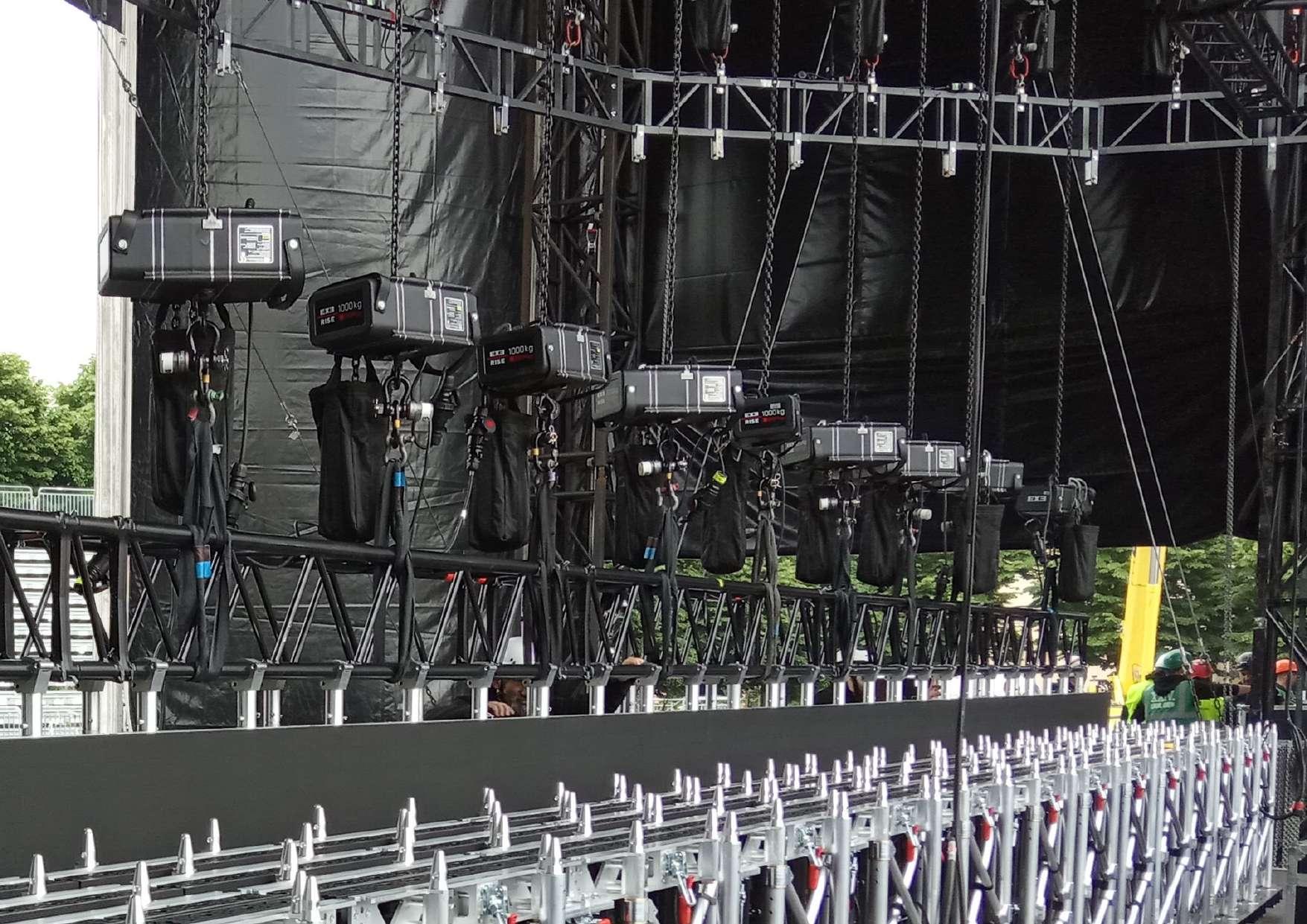
EXE CELL WIRED LOAD CELL SYSTEMS
MONITORING AND CONTROLLING LOAD
EXE Cell is a system developed to add the over and under load safety function to the machine by monitoring and controlling the load in real time, equipped with an intelligent and intuitive software.
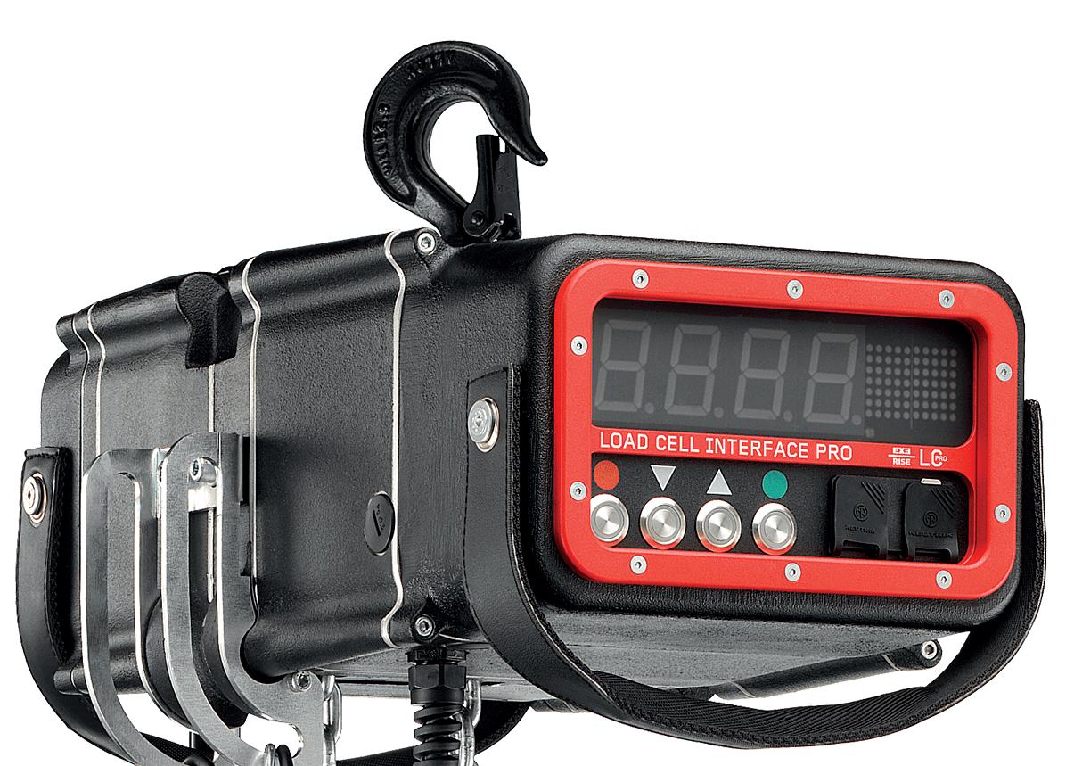
LC-PRO
Winner Awards for innovation of PLASA2015, is a system fully integrated in the EXE Rise chain hoists. Embedded load cell components within the body hook allows for true zero loss of headroom. The real time load is also viewable on a color multifunction display, protected by a durable polycarbonate screen.

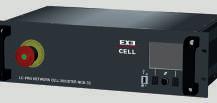
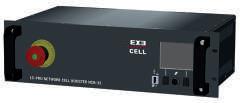
LC-NLP
EXE Cell LC-NLP configuration is a standalone system capable of detecting and monitor accurate weight measurements using DynaCell Load Cells, adaptable to any applications: LED walls, ceilings, trusses, big support, etc. lightweight solution to transport, quick to install and capable of lifting weights up to 7.5 tons.


01


WIRED LOAD CELL 3 Overview
LC-NLP & + + +
7 PIN
4 PIN
5 PIN LC-PRO4 HOIST LC-DYP DYNACELL LC-DY DYNACELL ANY HOIST + LC-DY DYNACELL EXE HOIST + LC-NLP H2T CELL HOOK LC-NLP16 NETWORK LOAD PROCESSOR EXE DRIVE CONTROLLER EXE DRIVE CONTROLLER LC-PRO4 HOIST & LC-DYP DYNACELL LC-NCB32 NETWORK CELL BOOSTER LC-PRO SOFTWARE LC-NLP SOFTWARE XLR 5 PIN ETHERNET ETHERNET or or or or
WIRED WIRED LC-PRO
XLR
XLR
XLR
LC-PRO
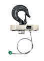
CHAIN HOIST & DYNACELL


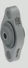
LC-H2T CELL HOOK
• Load cell fully integrated into the hook plate assembly
• Solid and robust, built to withstand the rigours of touring
• Easy to upgrade from a standard hook. Simply fixed in place using two bolts
• Cable from load cell to display is routed inside the hoist for additional durability
• No loss of headroom compared with external load cell systems
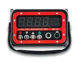
LC-PRO4
LOAD CELL DISPLAY PANEL
• Calibration of loadcell via link connectors for easy setup without dismounting the hoist
• Two panel display, one to show 4 digit weight (132x47 mm) and a second 2 digit display (45x39 mm) has the possibility to select between pounds or kilograms. Both displays are mounted behind a durable polycarbonate protection screen
• Dual color multifunction display to show system calibration set up and real time weight loading, with adjustable brightness and auto power off functions.
• Automatic display reverse option to provide easy to read, clear display in either body up or body down operation. Backup power supply via battery.
• Optional available Li-ion battery to mount inside the Cell Display that is able to power the load cell without using any external power supply via link cable connector, for more details please read the instruction manual.
• “Zero” value setting (Tare) function, shows the weight of the suspended load only and not the self-weight of the hoist. Double load / sleeve block / reading setting. Setting over and under-load


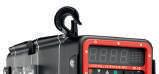
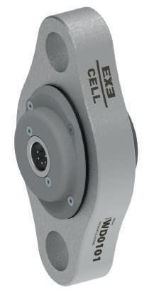
LC-DYP
WIRED DYNACELL
• The EXE CELL LC-DYP WIRED DYNACELL is a cutting-edge addition to the market boasting a sleek and ergonomic design that combines style with functionality. This innovative product comes in two distinct models, catering to varying load capacities of 0.5t and 5t.
• The 0.5t model is crafted from lightweight yet durable aluminum, striking a balance between strength and maneuverability. It offers reliable performance, capable of safely and efficiently handling moderate to heavy loads with ease.
• The 5t model is constructed from robust stainless steel, ensuring enhanced durability and resilience, making it ideal for tasks requiring higher load capacities and enduring harsh environmental conditions.
• In addition to its exceptional build quality and load-bearing capabilities, both models feature a fully recessed 7-pole XLR connector with a male-female configuration.
EXE CELL 4
+ WLL 0.5t WIRED DYNACELL XLR 7 pin WLL 5t WIRED DYNACELL XLR 7 pin WIRED
LC-PRO
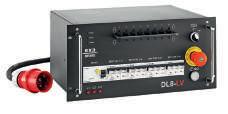
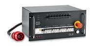
NETWORK CELL BOOSTER
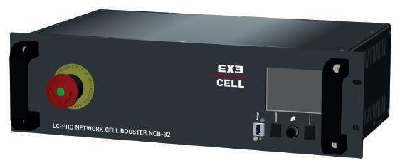
LC-NCB32
NETWORK CELL BOOSTER
• Powers up to 32 EXE Cell LC-PRO interface modules via two XLR 7 Pin output lines
• Rack mountable - 2U
• Front panel includes Data and Power on LED indicator lights
• 1 x Emergency Stop mushroom button
• Power inlet and Auxiliary out via Powercon connectors on rear (16A max). Auto sensing voltage selector
• Can be connected to EXE Drive controllers and linked to activate E-stop network in case of OVER / UNDER load
• Multiple Boosters and EXE Drive units can be linked together. Max 64 channels on one network
• 2 x Powercon relay outputs on rear. These can be used to trigger flashing beacons or audible sounders as an additional warning in case of Over / Under load
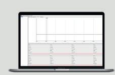
EXE Cell LC PRO app software is free and very easy to use. It is possible to set maximum (overload) and minimum (underload) load limits for each hoist directly from the PC interface. If the load monitoring detects a hoist that reaches one of these pre-set limits, the hoists will stop. In addition to this, you can also set a lesser load value than the maximum and minimum limits that will act as a visual warning that the system is approaching the pre-set cut out points.


WIRED LOAD CELL 5
LC-PRO SOFTWARE
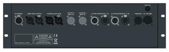
FUSE T5A RELAY I / RELAY II Output Max 2A. 1 x Powercon connection external warning device CONTROLLER DATA 1x 5pin XLR. (IN-OUT) LIMIT STOP OUTPUT 2x 4pin XLR. Hardware E-Stop connection NETWORK Input from PC EXE Cell software LC-PRO INTERFACE 1-16 1x 7pin XLR-M and 1x 7pin XLR. Power to EXE Cell. LC-PRO INTERFACE 17-32 1x 7pin XLR-M and 1x 7pin XLR. Power to EXE Cell. THROUGH 1x Powercon. AC 100-230V 1x Powercon. WIRED back view front view


EXE CELL 6 WIRED
7 PIN XLR male 7 PIN XLR male 7 PIN XLR female 7 PIN XLR female
LC-NCB
ETHERNET SWITCH CONTROLLER CONTROLLER LC-PRO SOFTWARE ETHERNET CABLE controller DATA + loadcell DATA ETHERNET CABLE controller DATA + loadcell DATA ETHERNET CABLE controller DATA + loadcell DATA 5 PIN XLR male HW E-STOP1 5 PIN XLR female 5 PIN XLR female HW E-STOP1 5 PIN XLR male 7 PIN XLR female 7 PIN XLR female 7 PIN XLR male 7 PIN XLR male 7 PIN XLR male 7 PIN XLR male 100m 100m 100m 100m 20m 20m 20m 20m 20m 20m 20m 20m 20m 20m 20m 20m 20m... 20m... 20m... 20m... 100m x16 x16 x16 x16 100m 100m 100m Configuration X16 X16 X16 X16
LC-PRO
LC-NCB 32
32


WIRED LOAD CELL 7 WIRED LC-PRO Compatibility chart D8+ 250/350kg DC / LVC 1 REEVE D8+ 500kg DC / LVC 1 REEVE D8+ 1000kg DC / LVC 1 REEVE D8+ 2000kg DC / LVC 2 REEVES D8+ 1600kg DC / LVC 1 REEVE D8+ 2000kg DC / LVC 1 REEVE D8+ 2500kg DC / LVC 1 REEVE MEDIUM FRAME AND ULTRA COMPACT MEDIUM FRAME LARGE FRAME EXTRA LARGE FRAME COMPACT EXTRA LARGE FRAME LC-PRO DISPLAY PANEL LC-NCB DYNACELL 0.5t 0.5t 5t 5t 5t 5t 5t ON DEMAND ON DEMAND ON DEMAND
EXE CELL 8
LOAD CELL 9
WIRED
LC-NLP
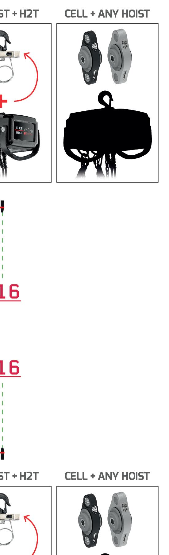
LC-H2T & LC-NLP DYNACELL

LC-H2T CELL HOOK
• Load cell fully integrated into the hook plate assembly
• Solid and robust, built to withstand the rigours of touring
• Easy to upgrade from a standard hook. Simply fixed in place using two bolts
• Cable from load cell to electric board is routed inside the hoist for additional durability
• No loss of headroom compared with external load cell systems.
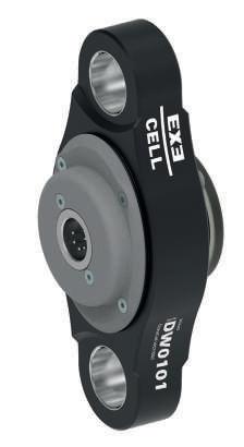

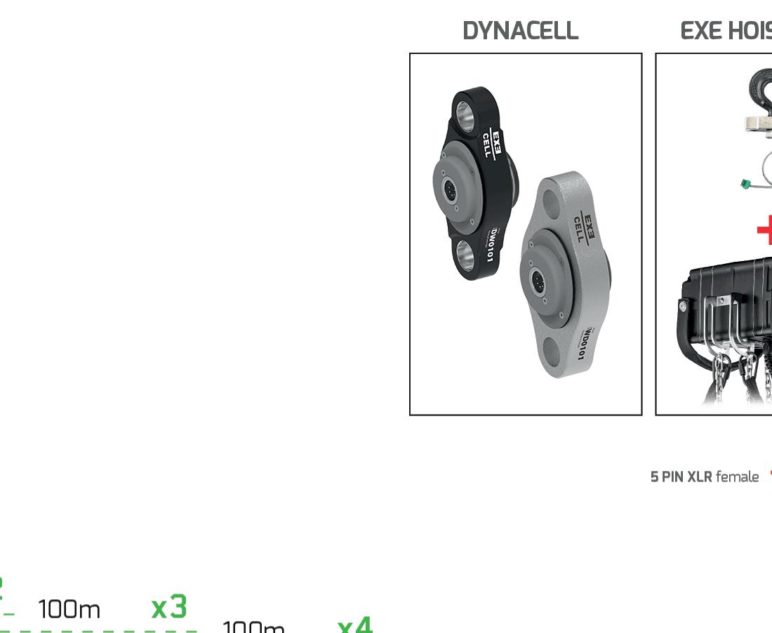
LC-DY WIRED DYNACELL

• The EXE CELL LC-DY WIRED DYNACELL is a cutting-edge addition to the market boasting a sleek and ergonomic design that combines style with functionality. This innovative product comes in two distinct models, catering to varying load capacities of 0.5t and 5t.
• The 0.5t model is crafted from lightweight yet durable aluminum, striking a balance bzetween strength and maneuverability. It offers reliable performance, capable of safely and efficiently handling moderate to heavy loads with ease.
• The 5t model is constructed from robust stainless steel, ensuring enhanced durability and resilience, making it ideal for tasks requiring higher load capacities and enduring harsh environmental conditions.
• In addition to its exceptional build quality and load-bearing capabilities, both models feature a fully recessed 7-pole XLR connector with a malefemale configuration.
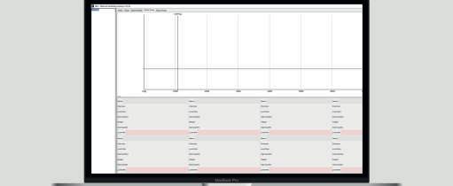
LC-NLP software is highly reliable and quick and easy to use; and is supplied included in the NLP16 package. It is possible to set both maximum (overload) and minimum (underload) load limits for each cell, plus the maximum and minimum warning levels.
EXE CELL 10
WIRED
0.5t LC-NLP SOFTWARE
LC-NLP
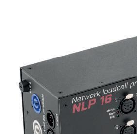
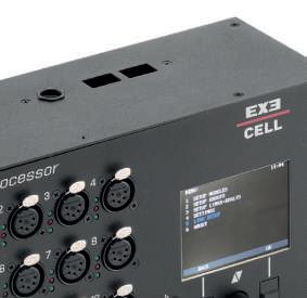
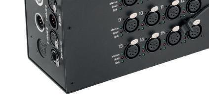
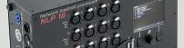
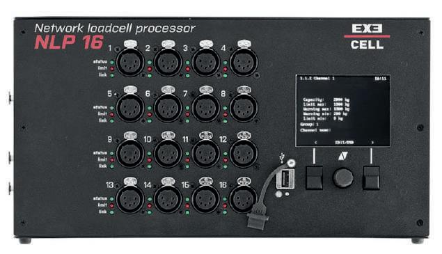
NETWORK LOAD PROCESSOR

LC-NLP16 NETWORK LOAD PROCESSOR
• The NLP16 is easy-to-use and user-friendly device developed by riggers.
• The NLP is a main unit that reads values from analog loadcell shackles with 4-20mA output and features the direct E-Stop output for rigging systems.
• A front TFT color panel display allows the viewing of loads and groups without needing an external PC while the universal power supply allows the system to be used worldwide.
• The NLP is not linkable.
• The ethernet connection to the switch allow viewing only and not the linking of multiple NLPs.
WIRED LOAD CELL 11
WIRED
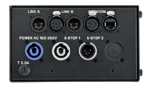
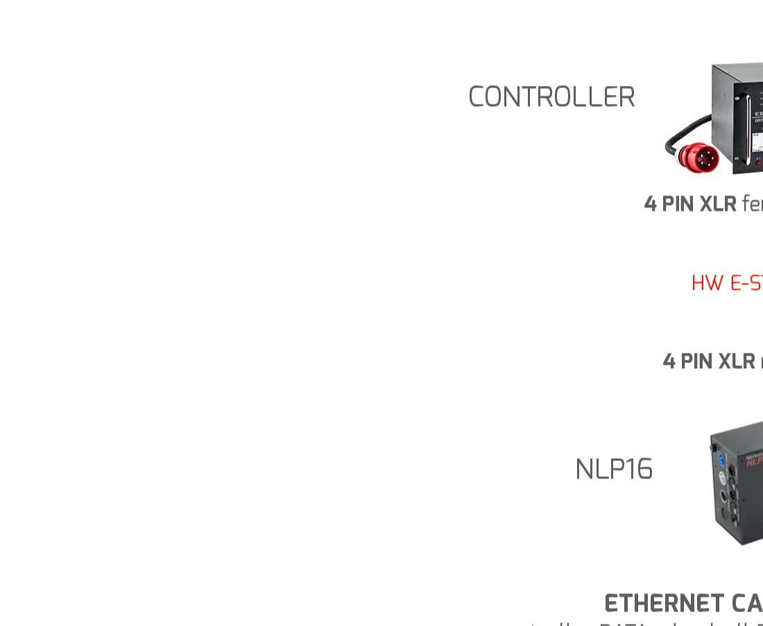
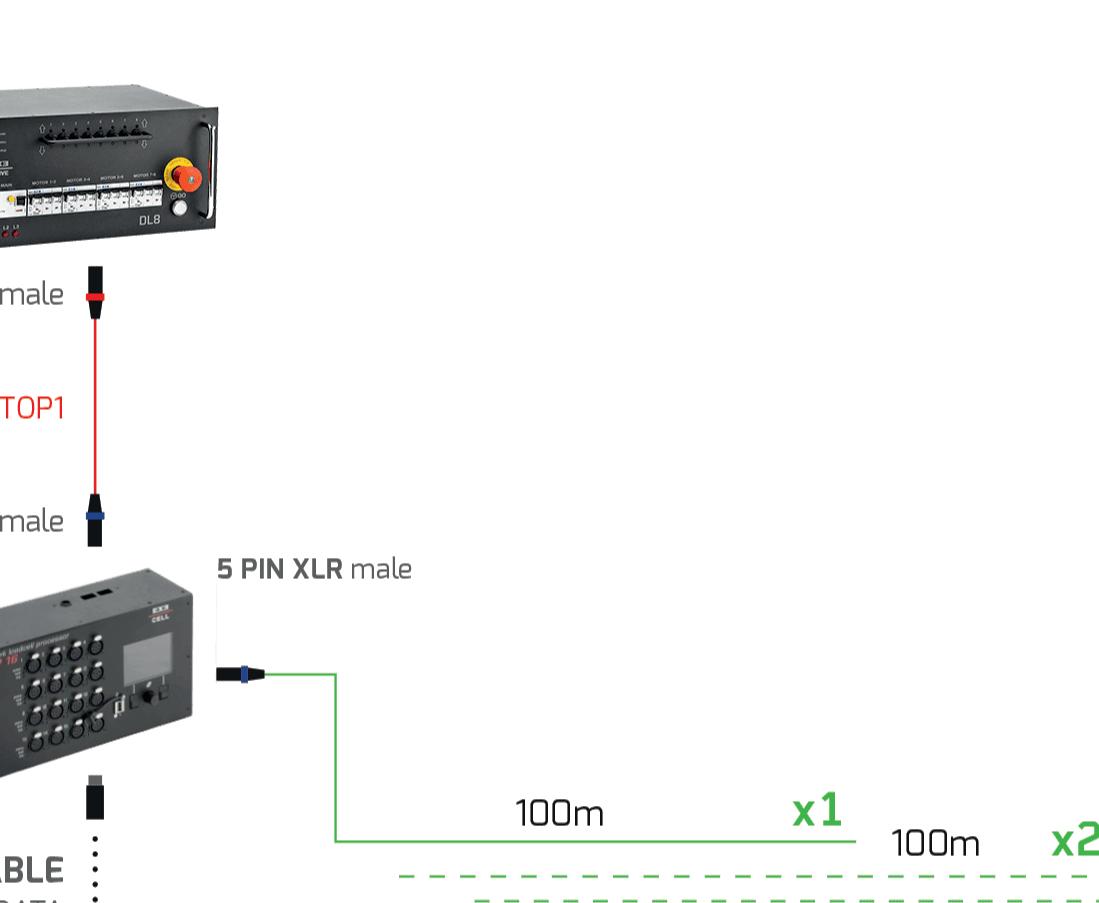
LC-NLP16 INTERFACE 1-16 16x 5pin XLR female -20mA input port for the loadcell connection LINK A CONTROLLER DATA IN / DATA OUT 1x 5pin XLR male 1x 5pin XLR female 1x POWERCON Power in 1x POWERCON Power link through E-STOP 1: LIMIT STOP IN Power link through LINK B CONTROLLER DATA IN / DATA OUT 1x 5pin XLR male 1x 5pin XLR female ETHERNET CONNECTION USB CONNECTION DISPLAY Large TFT full color display front view side view

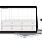
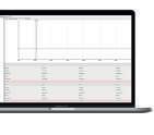


(indipendent and non linkable group)
(indipendent and non linkable group)
EXE CELL 12 WIRED
Configuration
LC-NLP
LC-NLP SOFTWARE


WIRED LOAD CELL 13
LC-NLP Compatibility chart D8+ 250 / 350 kg DC / LVC 1 REEVE D8+ 500kg DC / LVC 1 REEVE D8+ 1000kg DC / LVC 1 REEVE D8+ 2000kg DC / LVC 2 REEVES D8+ 1600kg DC / LVC 1 REEVE D8+ 2000kg DC / LVC 1 REEVE D8+ 2500kg DC / LVC 1 REEVE MEDIUM FRAME & ULTRA COMPACT MEDIUM FRAME LARGE FRAME EXTRA LARGE FRAME COMPACT EXTRA LARGE FRAME 0.5t 0.5t 5t 5t 5t 5t 5t
WIRED


EXE Flexa, the wireless world


From the experience of wired cells, an entire range of wireless devices has emerged. Now, Flexa Sensors is fully part of the large EXE family, giving a further boost to technological innovation in the field of load handling and control in absolute safety.


EXE Flexa features standalone wireless load cells or integrated ones on hoists. It is based on two distinct platforms with two different communication protocols.


EXE FLEXA WIRELESS LOAD CELL SYSTEMS

REAL-TIME
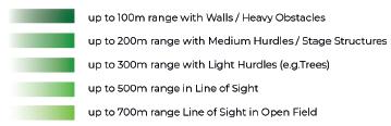
The Real-Time line is more suitable for managing up to a hundred of wireless cells. The system needs a local PC connected to a Gateway. Data are updated every second.
IoT
The IoT line is suitable for managing large networks with thousands of nodes that connect to the Cloud through one or more Gateways. Data are updated approximately every 3 minutes. All information can be accessed by multiple devices connected to the Internet.


02


WIRELESS


WIRELESS LOAD CELL 17 Overview
WIRELESS FW-CDY FW-MDY FW-MGW FW-CSH FW-HKT FW-CGW REAL-TIME IoT WIRELESS WIRELESS UPDATED EVERY SECOND UPDATED EVERY 3 MINUTES
USB DYNACELL 0.5t / 5t
0.5t / 5t LORAWAN ® GATEWAY SHACKLE 3.25t / 4.75t HOIST PANEL GATEWAY SOFTWARE PORTAL LOAD CELL ACTIVATION THROUGH MAGNETIC KEY
CLOUD
DYNACELL


REAL-TIME
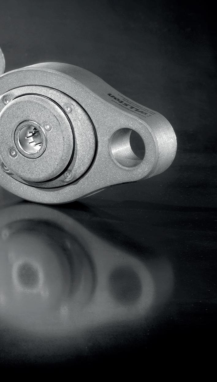
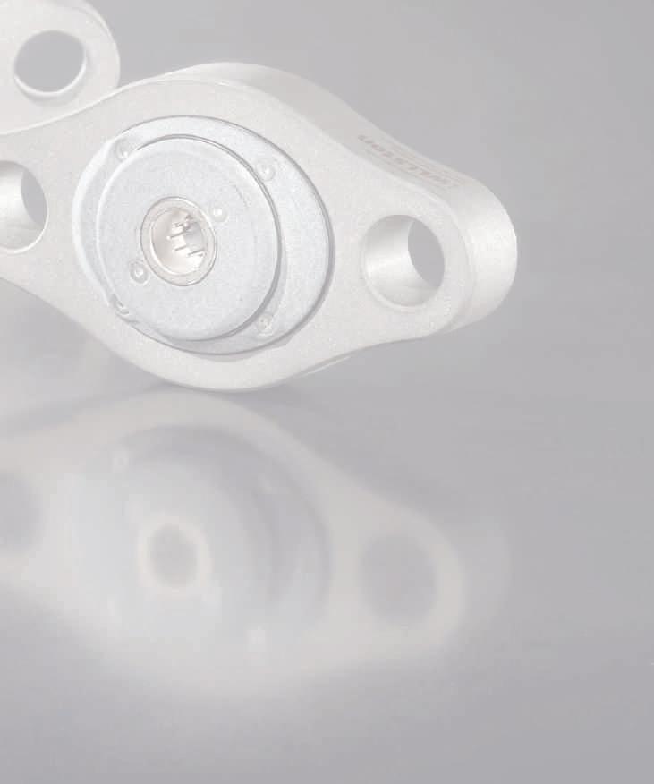
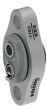
DYNACELL & SHACKLE


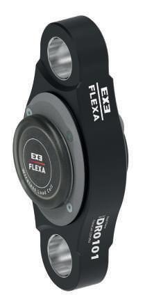


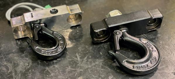
FW-CDY
WIRELESS DYNACELL
• DynaCell expands the EXE Flexa control eco-system’s scope with a unique, ultra-compact and totally versatile range of wireless load cell sensors.
• A new, super-stylish, ergonomic design is available in two models: the 0.5t WLL aluminium version and the 5t WLL stainless steel version.
• Both have an 8:1 safety factor and a IP65 rating.


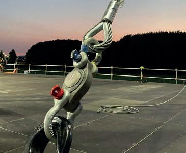
FW-CSH
WIRELESS SHACKLE LOAD CELL
• The shackle cell is a preferred standard among riggers. It is based on Van Beest shackles and are supplied in two versions: 4.75t and 3.25t WLL.
• Safety factor of 5:1 and IP65 rating.
EXE FLEXA 20
WIRELESS
EVERY SECOND
UPDATED
0.5t
DYNACELL & SHACKLE

DYNACELL, THE MOST VERSATILE EVOLUTION
WIRELESS LOAD CELL
DynaCell is available in both aluminium and stainless-steel versions and measures 12cm between hole centres. The aluminium model weighs only 300g and is provided exclusively in a black anodised version. The stainless-steel model weighs 980g and comes with a matte, sandblasted steel finish.
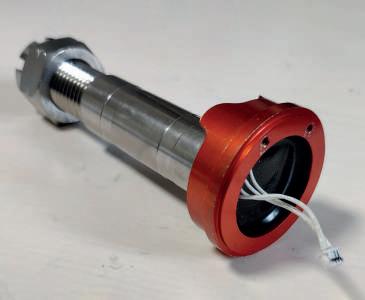
THE SHACKLE LOAD CELL, THE REINVENTED STANDARD.
Four strain gauges are embedded in the resin inside the pin. No external cavities and the high technological level ensure maximum safety. The CR 123 batteries are compact and borrow design features from the camera industry to ensure stable performance and long life. The cylinder shape of the enclosure limits shocks and the anti-rotation ring is integrated into the pin, leaving the upper part of the shackle free.


To ensure high IP protection , the cells are not equipped with external mechanical switches. Instead, a magnetic key provided with the cells can activate a magnetic switch, which is turned on or off by placing the key close to the cell’s cylindrical cap (for Real-Time and IoT lines only).
WIRELESS LOAD CELL 21
WIRELESS UPDATED EVERY SECOND FW-UMK MAGNETIC KEY
REAL-TIME
REAL-TIME
WIRELESS HOIST CELL PANEL


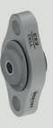
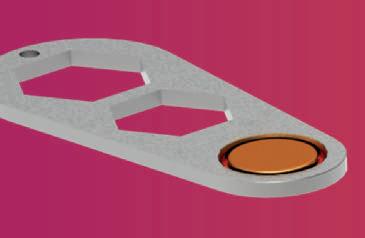
LC-H2T
CELL HOOK
• Load cell fully integrated into the hook plate assembly
• Solid and robust, built to withstand the rigours of touring
• Easy to upgrade from a standard hook. Simply fixed in place using two bolts
• Cable from load cell to display is routed inside the hoist for additional durability
• No loss of headroom compared with external load cell systems

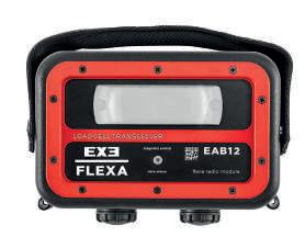

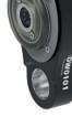
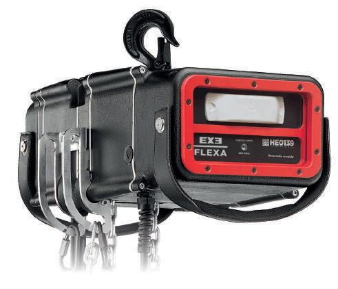
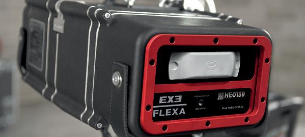
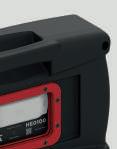
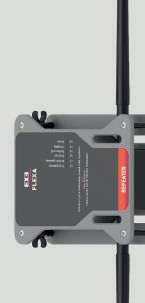
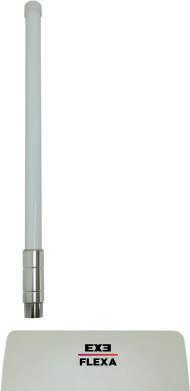
FW-HKT
WIRELESS LOAD CELL PANEL
• Wireless calibration of loadcell for easy setup without dismounting the hoist.
• Ultra-low profile, wall panel, robust, tamper proof design antenna.
• On/Off magnetic switch under the front panel for a high IP level.
• RGB LED status indicator.
• The Load Cell and Radio Module are powered with four C batteries
• No tools are needed to access the batteries
• Battery-saving smart transmission strategy: it transmits every second when the load change exceeds a configurable threshold, transmits less often when the load is stable keep on reading every second.
• The transmission automatically switches off in case of long inactivity to reduce battery consumption.
EXE FLEXA 22
WIRELESS UPDATED EVERY SECOND
+
REAL-TIME
WIRELESS HOIST CELL PANEL
UPDATED EVERY SECOND
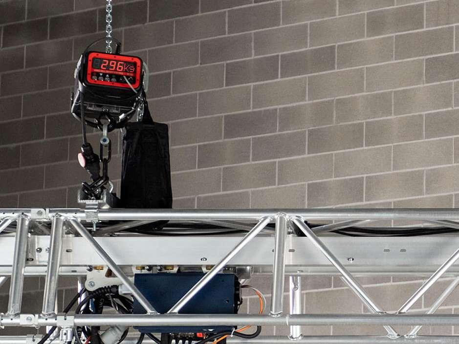
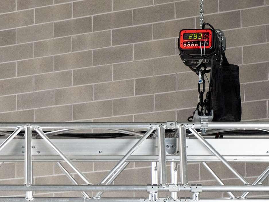
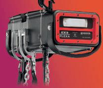
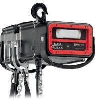
EXE ELECTRIC CHAIN HOIST GOES WIRELESS!
THE CELL INTEGRATED IN THE HOOK
The load cell module is perfectly integrated in the steel block that connects the electric chain hoist to the hook. This setup eliminates external wires without losing any height. compared to a solution based on an external cell. A true technological masterpiece!
EXCLUSIVE DESIGN
The EXE Flexa module with the microprocessor and the radio section is mounted on one of the two hoist side covers. The externally mounted anti-shock antenna offers a high degree of efficiency, even in difficult conditions for radio waves, such as in stage roofs.
The module is connected to the LC-H2T cell hook, which integrates the load cell inside the hoist hook of the EXE Rise electric chain hoist. The final result is a unique design with unparalleled practicality for daily use.
EXE CHAIN HOIST


WIRELESS LOAD CELL 23
WIRELESS
WIRELESS CELL PANEL COMPATIBILITY MEDIUM FRAME MEDIUM FRAME COMPACT LARGE FRAME EXTRA LARGE FRAME EXTRA LARGE FRAME COMPACT


REAL-TIME
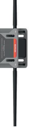
GATEWAY & REPEATER
FW-CGW GATEWAY
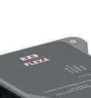


• The Gateway is not a merely a simple data conveyor; it’s an intelligent machine that constantly communicates with cells or repeaters.
• Four RGB LEDs
• Plug and play installation (no radio set up)
• Max number of cells: 100 units
• USB-A port to PC

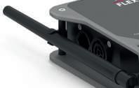


FW-CRP REPEATER
• To cover distances over 600m between cells and gateway, or when significant obstacles must be overcome, it may be necessary to add one or more repeaters
• Six RGB LEDs
• Wireless connection from cells to the gateway
• Max No of Repeaters per Gateway: 5 units
• Transceiver with 2 antennas
Under normal operating conditions, the gateway adequately covers the working area, but a repeater is necessary when the distance to the cell is greater than 500/600m or when significant obstacles must be circumvented using devices in triangulation. The system requires the gateway to always be on, to maintain the connection with the load cells. If the load cells are on and don’t find their active gateway, the cells will consume a lot of battery. For this reason, each gateway has three power systems that make it independent of the PC connection.
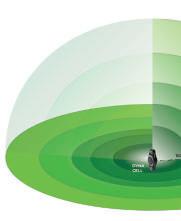
Environmental conditions affect every radio transmission.
The distances calculated in line of sight on an open field are different from the real ones in the presence of different obstacles. The graphs show different ranges, based on the environment in which the system operates.

In most common uses, the gateway connects directly to active cells. In critical radio signal transmission conditions, repeaters may be necessary. In this case, the gateway connects exclusively to the repeaters (up to a maximum of five units).
EXE FLEXA 24
WIRELESS UPDATED EVERY SECOND
REAL-TIME
CONTROL SOFTWARE
FROM CELLS TO SCREEN
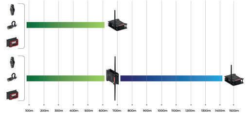
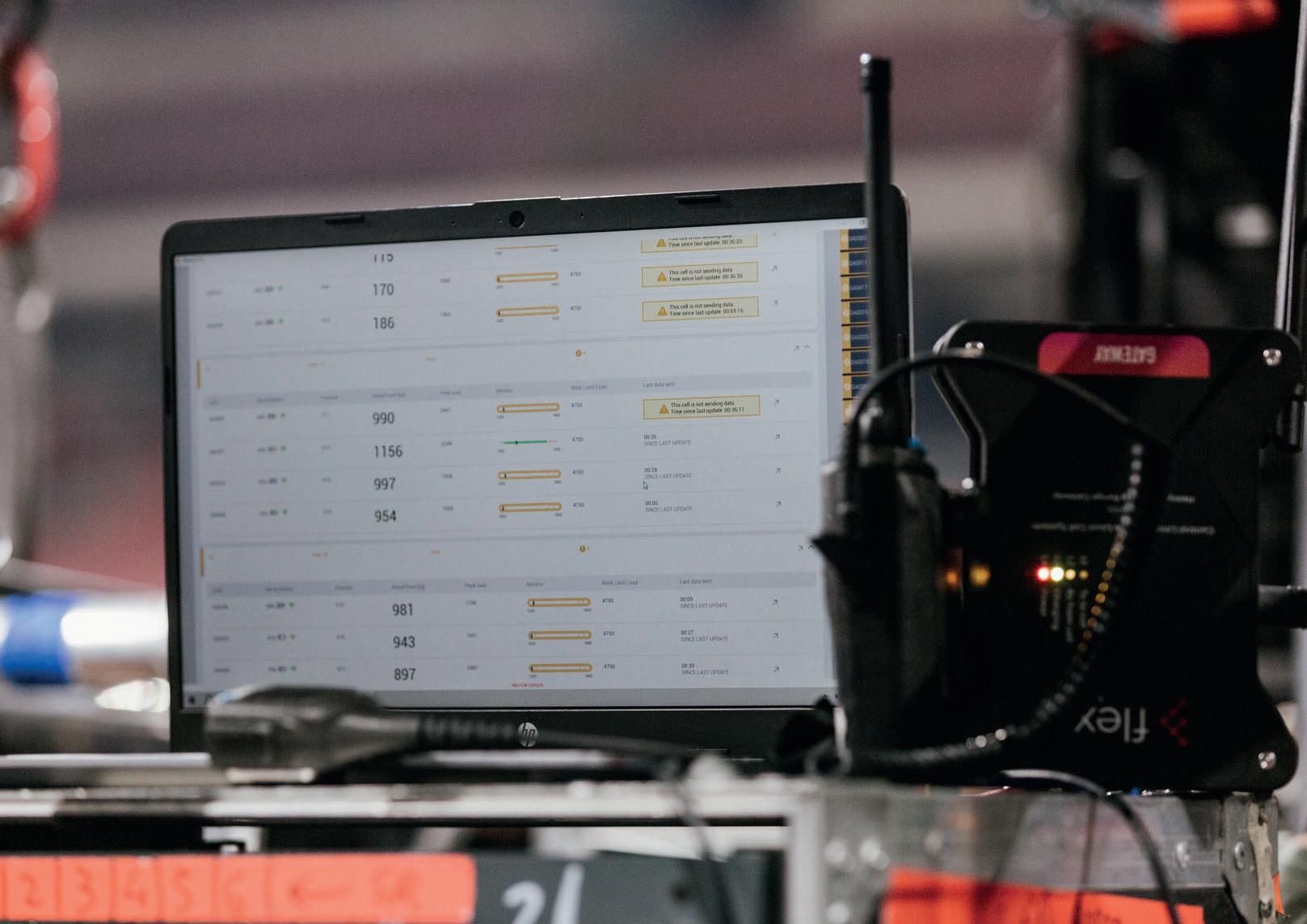
EXE FLEXA CONTROL SOFTWARE
The Flexa Control software is the operational intelligence that allows the management of cells and all parameters. The information is grouped by Event, Sectors, and Zones. Each zone is populated by cells.
For each cell, information on the load, its history, load charts, battery charge values, and the radio signal quality is always available. Each sector, zone, or cell has its own interface page that can be opened individually or simultaneously with other pages on multiple screens.
For data visualisation, the PC must always be connected to the Gateway with the USB cable. Without this condition, data can’t be visualised, and all information coming from the cells will be lost. The gateway must remain on even without the PC connection, just to mantain the network of connected cells on. The software is available for Microsoft Windows OS, and Apple MAC OS.
TRY OUR SOFTWARE EVEN WITHOUT HAVING THE CELLS
Our software is ready to manage the cells. In addition, it has a test section that allows you to simulate the operation with virtual cells: you can create your event, divide it into sectors and zones and populate it with cells. An automatic process will simulate virtual load readings that will respond to the load limits you have entered for each cell.
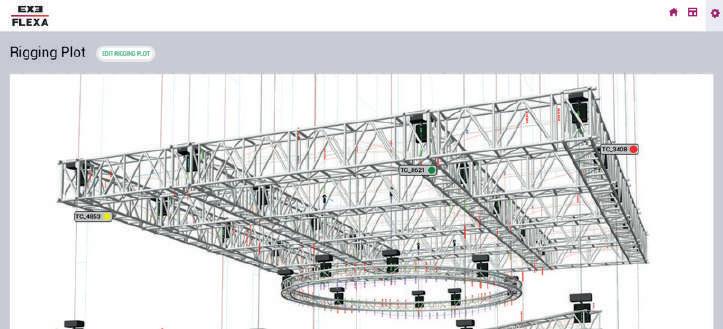
DRAG & DROP ON YOUR RIGGING PLOT
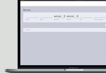
The updated version, operational from March 2023, of the Flexa Control software allows for the manual placement of cells overlaid on an image, typically a rigging plot, for immediate viewing of the cell’s position with an indication of the code, load, and signaling of load level status.
WIRELESS LOAD CELL 25
WIRELESS UPDATED EVERY SECOND
WIRELESS
UPDATED EVERY SECOND
LOAD CELL ACTIVATION THROUGH MAGNETIC KEY


REPEATER


In case of problems in signal propagation, a repeater can be placed between the cell area and the gateway. The distances between the repeater(s) and the gateway depend on the environmental conditions (typically up to 700m in line-ofsight). Up to 5 repeaters can be managed by a single gateway.


System designed to measure loads in real time with weight reading every second. Battery-saving smart transmission function, transmitting every second when the load change exceeds a configurable threshold, less often when the load is stable. The distances between the cells and the gateway depend on the environmental conditions (typically up to 600m in line-of-sight).
EXE FLEXA 26 Configuration
SHACKLE
REAL-TIME
EXE HOIST
3.25t
4.75t
WIRELESS DYNACELL
/
GATEWAY USB 0.5t
5t SOFTWARE
WIRELESS CELL PANEL
/


Based on

THE LOAD IN THE CLOUD


FW-MDY
WIRELESS IoT DYNACELL
• LoRaWAN® compliant
• WLL 0.5t & 5t (S.F.: 8:1)
• ENAW-2024 T351 Aluminum
• 300g self-weight
• Smooth design


FW-MGW
LORAWAN® GATEWAY
• LoRaWAN® compliant
• Range covered > 1000m
• 220V AC supply/PoE
• ChipSIM MFF2 included
• MicroSIM slot
• Ethernet
CLOUD OPERATING IoT LINE
The IoT line is natively built on the cloud, following the Internet of Things trend. Each cell measures the associated load and transmits every three minutes (on average) to the cloud via gateways, following the LoRaWAN® standard.
This solution is suitable for managing hundreds of load cells or other sensors. The main purpose is to continually monitor loads with many hanging points over large areas, in order to compare the hanging loads with the building’s structural limits.


EXE FLEXA 30
IoT WIRELESS UPDATED EVERY 3 MINUTES
Cloud

The powerful Gateway for indoor and outdoor applications. Business-grade LoRaWAN® Gateway
The EXE Flexa IoT Gateway is the latest business-grade model of LoRaWAN® Base station. Thanks to its aluminum housing design and the use of waterproof components and connectors, it ensures an IP67 rating. It is specifically designed for outdoor applications or indoor environments subject to dust or moisture.
The gateway operates within a range of industrial temperatures, from -40 °C to +85 °C. This makes our device suitable for all environmental conditions, which is the main reason for its widespread market success. It provides durable, lowpower, wide-area connectivity to support M2M and IoT applications.

GLOBAL CONNECTIVITY FOR YOUR DEVICES!
The Chip SIM MFF2 included and ready to be activated and MicroSIM 3FF slot available for worldwide connectivity! In addition you can use your own SIM Card
A B C
WIRELESS LOAD CELL 31 UPDATED EVERY 3 MINUTES THE
IoT WIRELESS
LOAD IN THE CLOUD
Cortex-A7 629MHz Modem 2G 3G/4G LTE RAM 512Mb GPS GNSS 4Gb eMMC Semtech SX1303 PoE 42-60V or 12-24V LoRaWAN® class support RS-485 ChipSIM MFF Slot Embedded sensors MicroSIM 3FF Slot Linux Yocto 4.1.15 Waterproof case Data Retention IP67
-40 to +85 °C 10%-95% H
THE LOAD IN THE CLOUD
The EXE Flexa IoT line is based on the LoRaWAN® network protocol, a worldwide connectivity solution. Only a robust and well-proven network protocol can monitor thousands of points over large areas. More information on LoRa Alliance WEB site
In the IoT line, each cell’s QR code is unique. By framing the code from the app, all the cell’s information can be accessed. The cell specifications can then be entered from the app and automatically transferred to the cloud portal without having to transcribe them.
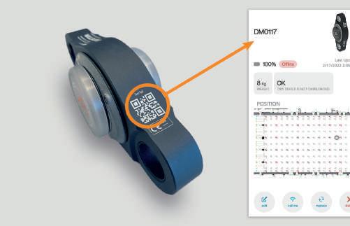

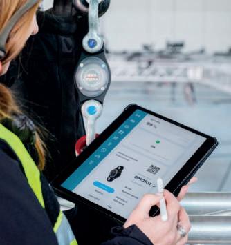
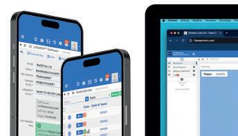
With our online access portal, all data is always available both on PC and on mobile devices.

This system is designed mainly for exhibition halls and any other applications where constant monitoring of hundreds of loads is required, even over large distances.
Hanging large structures from trade fair ceilings has been an established trend for many years, and almost all exhibition centres set load limitations for each individual ceiling hanging point. Clearly, without load measurements no one is able to define exactly how much weight is attached to each single point. Wireless load cells are the simplest and most precise answer to this need.
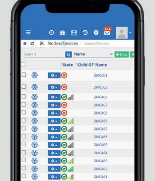
In an exhibition hall, many “nodes” (hundreds or even thousands) can read the applied load. They must be accessible via several devices at the same time.
EXE FLEXA 32
IoT WIRELESS UPDATED EVERY 3 MINUTES


The EXE Flexa Portal is designed to manage wireless load cells in trade fair pavillions
Each event is divided into halls, each hall is made up of stands, and each stand includes its own cells or other sensors. Cells can be in the same building, in adjacent buildings, or even in different geographical locations.
The portal’s design has been crafted to be easily scalable and to address various requests beyond the trade fair sector.
LoRaWAN® IS A LOW POWER, WIDE AREA (LPWA) NETWORKING PROTOCOL
The LoRaWAN protocol is widely used worldwide and is regulated on Sub1GHz frequencies. It’s a common platform for IoT devices, particularly for long-range applications.
The offer of LoRaWAN® IoT devices is growing day by day.
Our cloud system is designed to accommodate everything that is LoRaWAN® compatible.
In addition to producing its own specific devices, EXE Flexa also researches and modifies other sensors that may serve a function in the specific sectors of exhibition and entertainment.

WIRELESS LOAD CELL 33 UPDATED EVERY 3 MINUTES THE LOAD IN THE CLOUD IoT WIRELESS

ACCESSORIES
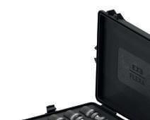
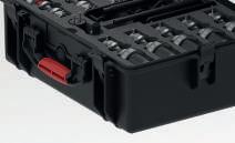
CARRYING CASE
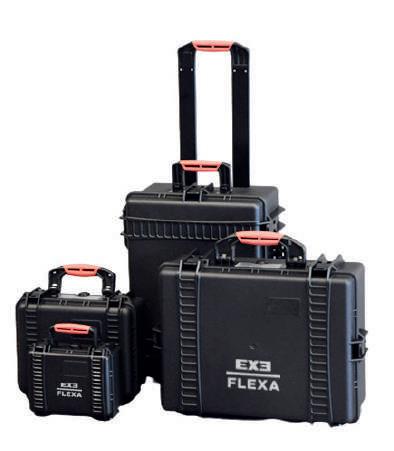


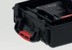

CARRYING & STORAGE SOLUTIONS PROTECT YOUR EQUIPMENT
Every professional in this industry must find a way to transport, store, and protect load cells and other devices. We have partnered with the manufacturers of the best hard cases in the world and selected a dedicated line of hard cases and customised interiors to completely protect the equipment against dust, water, shocks, and chemical corrosion.
They’re watertight and resistant to dust, moisture, acids, and sand. They also have a special valve that automatically adjusts the air pressure inside the case. The cases provide maximum protection with minimal weight. They withstand falls and impacts and offer unparalleled protection and an easy storage solution for every tool of this trade. SC21
• Single load cell case SC23
• Gateway or Repeater case


SC26 K06B SUITCASE
• 6 shackle or 6 DynaCell case
• Slots for 1 Gateway and 1 Repeater


SC26 K10B
SUITCASE

• 12 Shackle or 12 DynaCell case
• Slots for 1 Gateway and 1 Repeater
ACCESSORIES 34
SUITCASE
SUITCASE
Manual calibration of radio channels
Internet connection required
Concurrent data access from multiple devices
Remote monitoring
Max number of Cells per Gateway
Max number of Gateways per System
Max number of Repeaters per System
Max number of Cells per LC-NCB32Module
Max number of LC-NCB32 Module per System
Max number of Cells per LC-NLP16 Module
Max number of LC-NLP16 Module per System
Max number of Cells per System User
COMPARISON CHART 35 3 Minutes Cloud Wireless Internet 868/915/923 MHz LoRaWAN® No Yes Yes Yes 300 20 ---1000 Yes Yes Yes 1 Second Local PC Wireless USB Cable 868/866/915/923 MHz Proprietary No No No No 100 3 2 ---100 Yes Yes No Instant LC-NLP 16 Module WIRED XLR Cable 5 PIN Ethernet Cable Proprietary No No No No ---16 2 32 Yes No No Instant LC-PRO NCB32 Module WIRED XLR Cable 7 PIN Ethernet Cable Proprietary No No No No -32 3 -96 Yes No No Data refresh period Data management platform Load Cell
to Gateway Gateway
platform Frequency Network protocol
connection
connection to
friendly platform Drag & Drop interface Management fees EXE FLEXA Real-Time EXE CELL LC-PRO EXE FLEXA IoT EXE CELL LC-NLP Comparison Chart
OVERVIEW
Our operations on Sub-1GHz frequencies are subject to regulation in accordance with local laws across various global regions. We are dedicated to standardizing our radio modules and incorporating firmware updates to ensure compatibility, even in regions necessitating adjustments to adhere to local legislation. The map shows the breakdown of frequency distribution across different areas of the globe. For additional information, please visit www.thethingsnetwork.org .
FREQUENCY MAP 36
WORLDWIDE FREQUENCY
868MHz 915MHz 866MHz (india) 923-925MHz
MAP
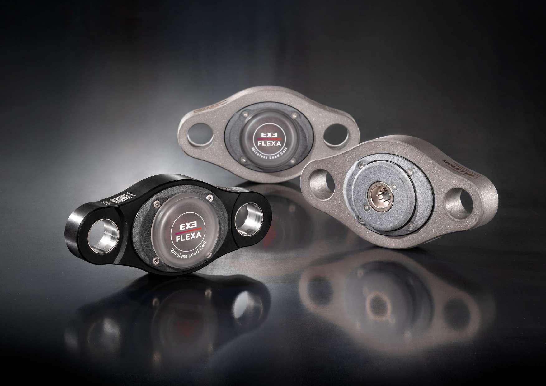
PHOTO CREDITS STUDIO POINTER https://studiopointer.com IMVISION S.R.L. www.imvision.it THE.STUDIO.ROCKS Ver. 24


EX=I� TECHNOLOGY Designed & Manufactured by: Area Four Industries Italia Distributed in UK, Ni & EIRE by: Area Four Industries Direct UK Tel +44 (0)1945 410700 info@la4industries.uk www.exetechnology.com TOMORROW INVENTED Area Four Industries
