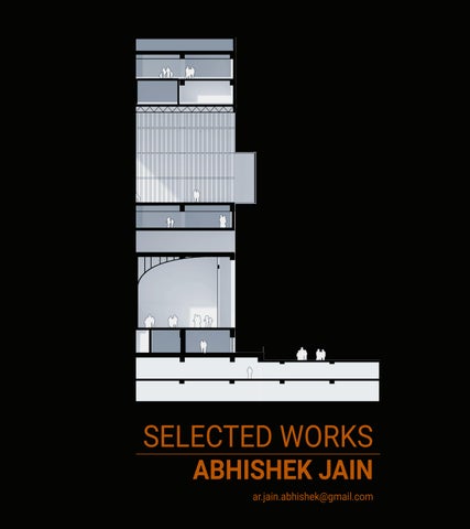
ABHISHEK JAIN SELECTED WORKS ar.jain.abhishek@gmail.com

current location email phone
Barcelona, Spain ar.jain.abhishek@gmail.com +34 617584916
d.o.b nationality
Specialism:
07.02.1997 Indian
Digital Fabrication
Parametric Workflows
Building Information Modeling
ABHISHEK JAIN
SELECTED WORKS | 2024
This portfolio contains selected projects and personal works from 2018-2024, each project is just for preview.
Hello, I’m a design professional with 4 years of work experience. Over this time, I’ve been consistently exploring modular design through the application of computation and BIM, both of which I have not only utilized but also taught. I’ve been involved in various international projects spanning across India, Bangladesh, Australia, and Portugal. My background encompasses work in institutional, commercial, transport, and residential sectors. My previous experience has allowed me to work in Institutional, commercial, transport and residential sectors. I constantly focus on the intricacies of design and imply the latest processes and technology in my work. Apart from my professional work, I try to implement new ways for form finding and fabrication as a digital artist using comteparary tools and approaches.
ABOUT ME
2015-20 2023-24
2023-Present
2021-Present
education
Bachelors Of Architecture from Faculty of Architecture and Ekistics, Jamia Milia Islamia, New Delhi
Masters in Advanced Architecture from Institute for Advanced Architecture of Catalonia
April 2022-April 2023
Novatr (Previously Onistox)
Industry Guide (Teaching Assistant) - BIM- Computational Design experience
Founder, Autonomous Polymorphic Explorations
Working to explore expermental design scenarios and test out theoretical framemwork for Data-driven design and computational methodologies
Building Designer at BDP (Building Design Partnership), New Delhi
Successfully delivered packages with detail design and coordination of large scale projects with a team of experienced designers from studios internationally. Key Projects:
- Project Lead, Uppercrest IT Park, Valsad
- Design Team, Interior Design, Nippon Koei Office, New Delhi
- Design Team, Detailing Design, Dhaka Metro Stations Line-5
Jul 2020-Apriil 2022
Architect & BIM Designer at Studio Next Architects, New Delhi
Was responsible for leading various projects from concept to execution, coordinating with client, contractors and consultants while managing a design team. Key Projects:
- Project Lead, Defence Colony Residence, New Delhi
- BIM Lead, 6 Single Family Homes in ACT, Australia (collaborated with Hyperspace Architects, Canberra)
- Project Lead, Private Residence, Portugal
- Project Lead, Commercial Complex for Deva Group, Begusarai
- Project Lead, 200 bedded hospital for SRHU Trust, Dehradun
- Project Lead, Athenia School Phase 3, Saharanpur
- BIM Design Lead, GST building, Ghaziabad
Jan 2020-Jun 2020
Intern Architect at Creators Architects, New Delhi
Key responsibilities included concept design and generation through use of BIM and parametric modelling in grasshopper. Key Projects:
- Design Team, School & Student Housing BMEF University, Surat
- Design Team, Multi-Purpose Hall Delhi Technical University, Delhi
- Design Team, GMDA Botanical Park, Guwahati
skills / activities
Native Languages
Other Languages
Digital Skills
Analog
Hindi - Punjabi
English - Proficient User Espanol - Beginner
Python -C++
Revit - Rhinoceros with Grasshopper - Autocad - Sketchup
Robotic Fabrication - Digital Fabrication - Machine Learning
Indesign - Photoshop - Twinmotion - Illustrator - Vray
Sketching - Model Making - Hand Drafting
EXPLORATIONS AND PERSONAL WORK
Deeper Exploration of Digital Tools, Fabrication Techniques and Experimental Design
|
2023
24


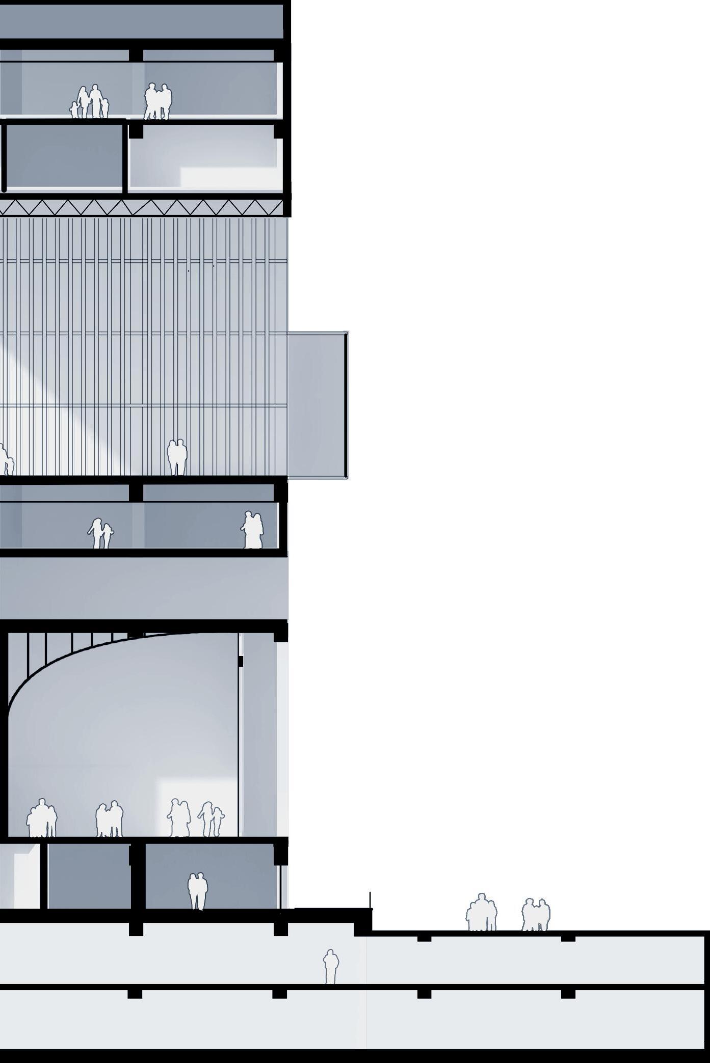
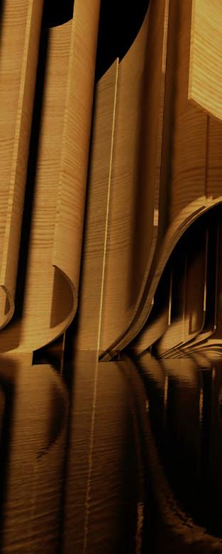
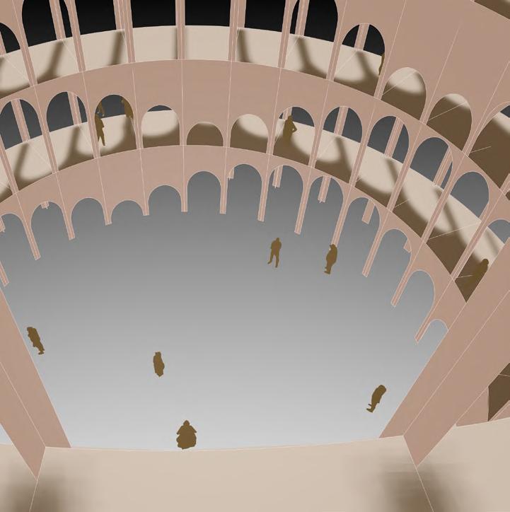
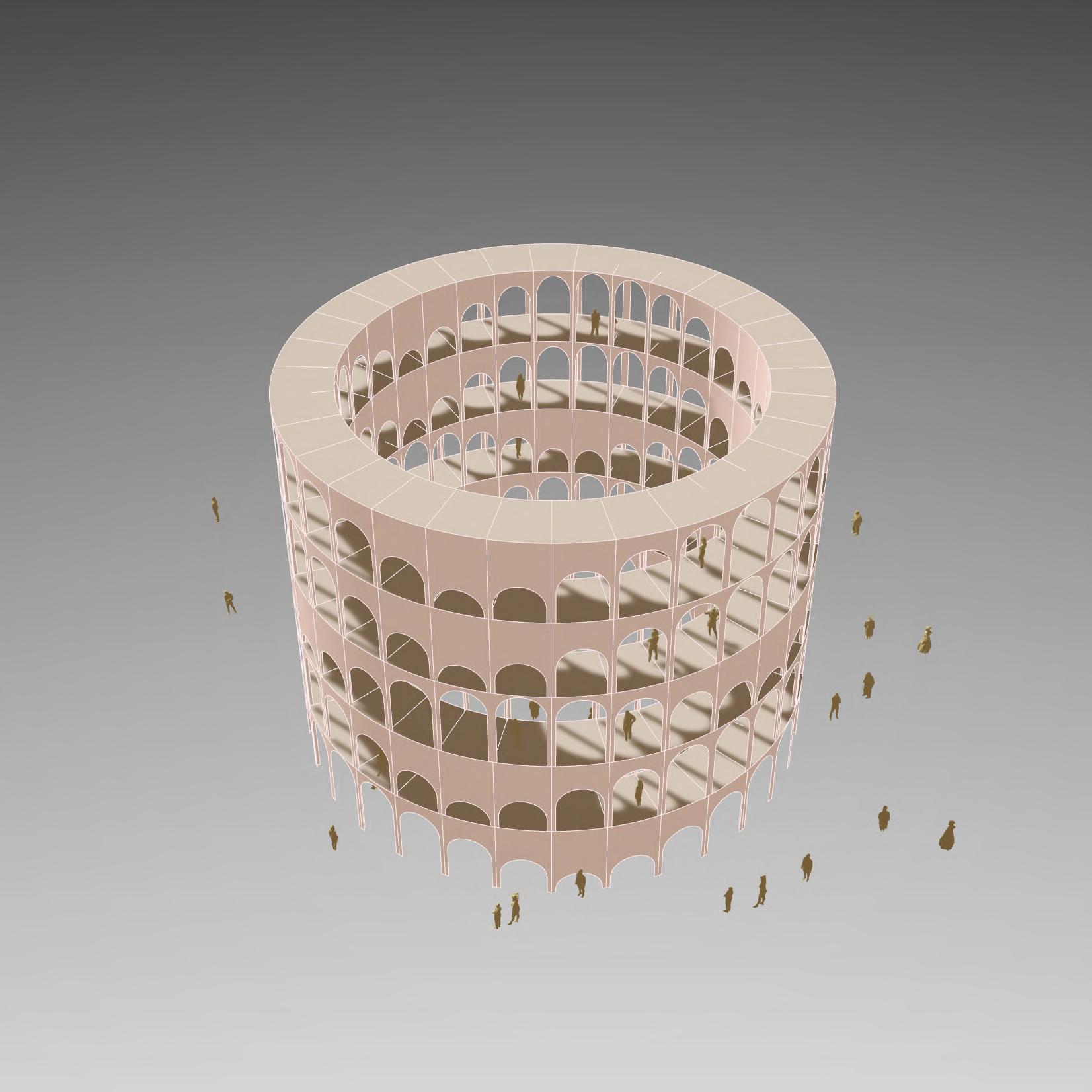
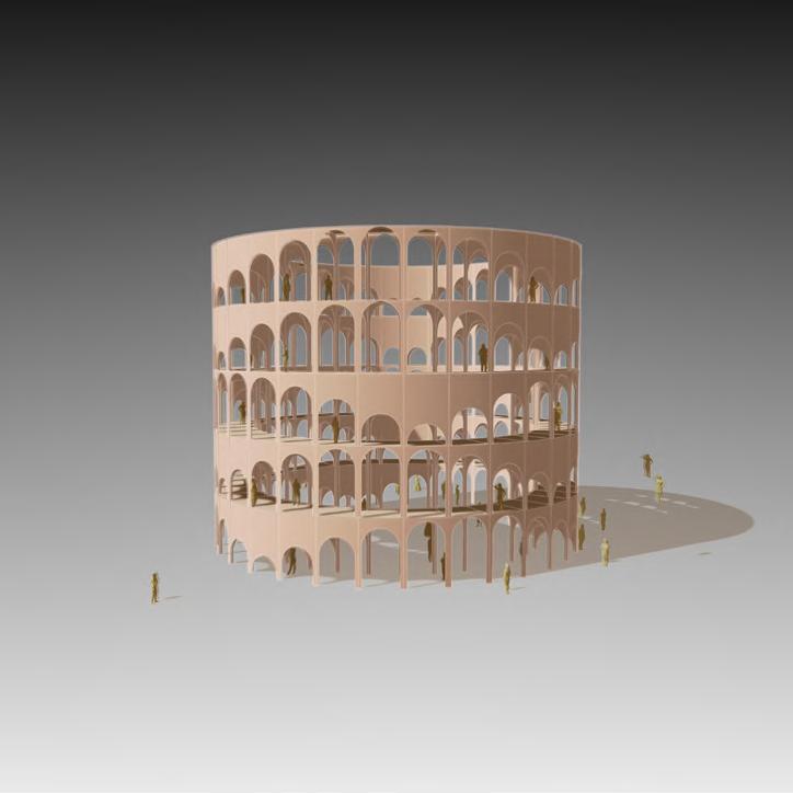
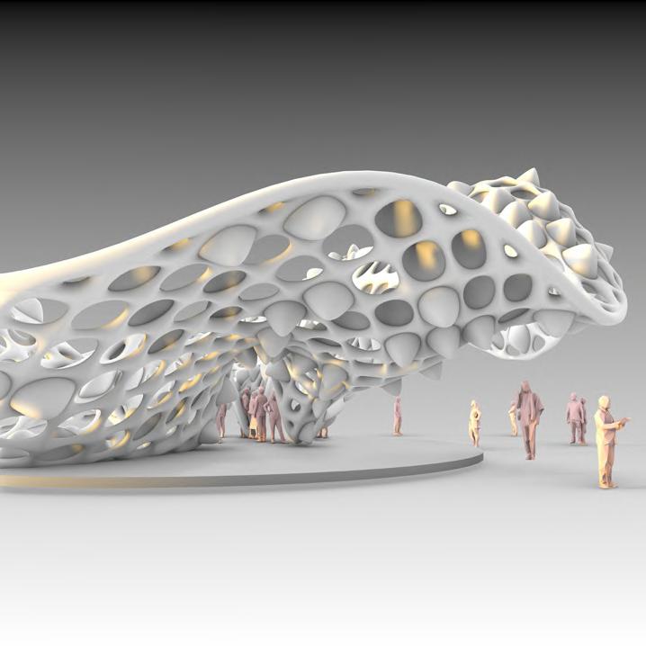
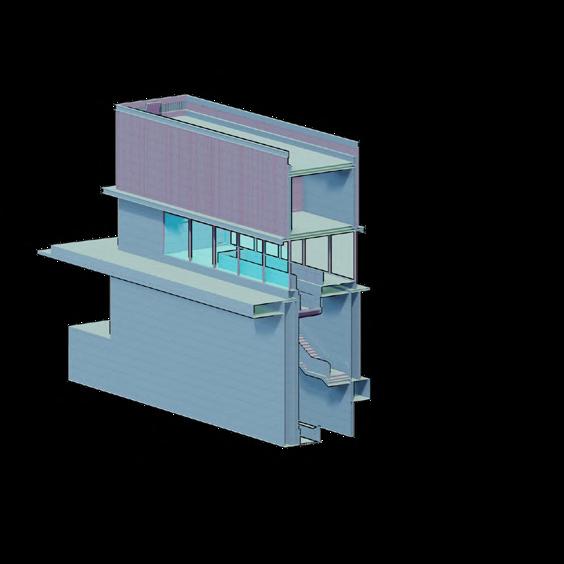
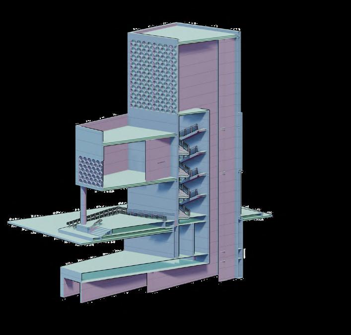
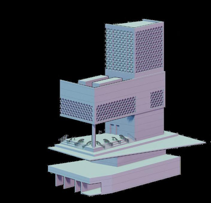
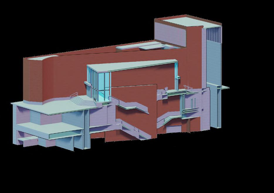
AFTER GAUDI : COMPUTATION TO COMPOSITION
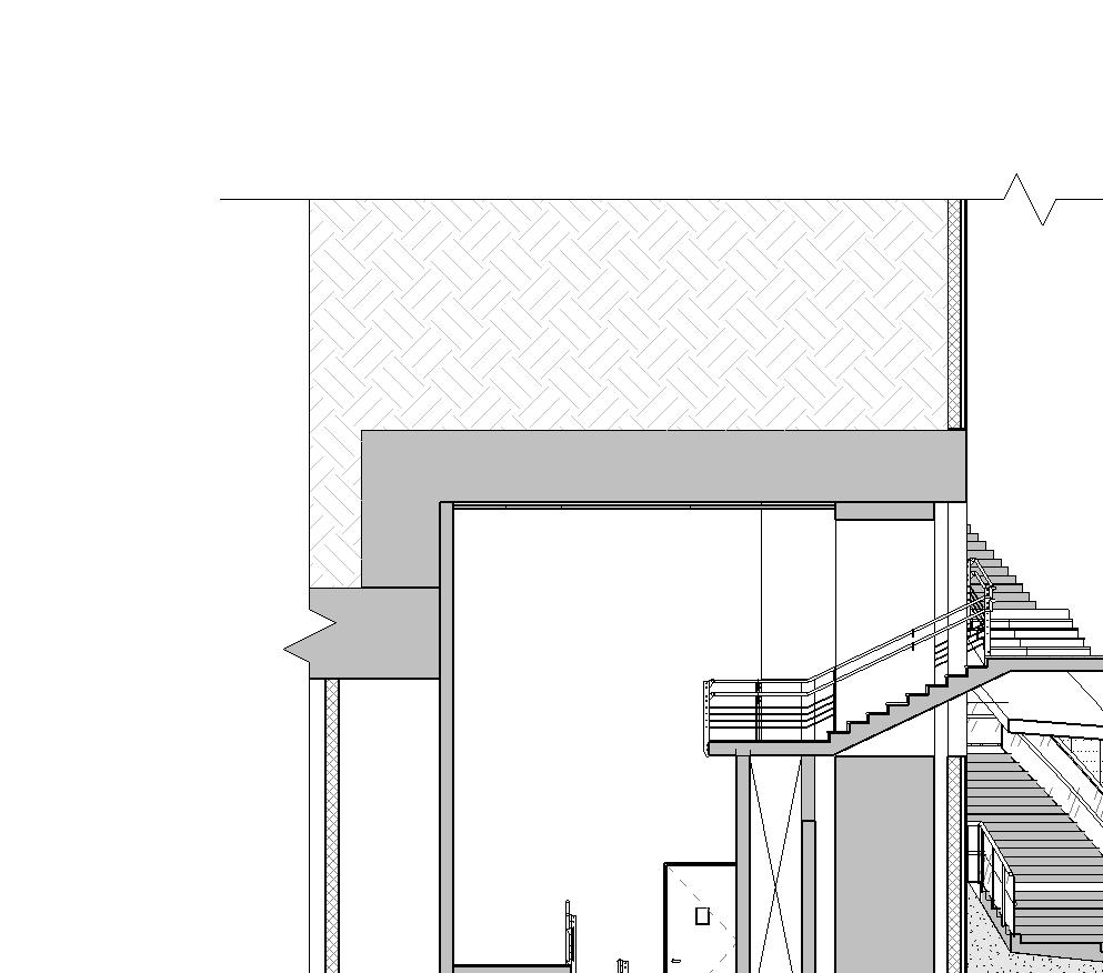
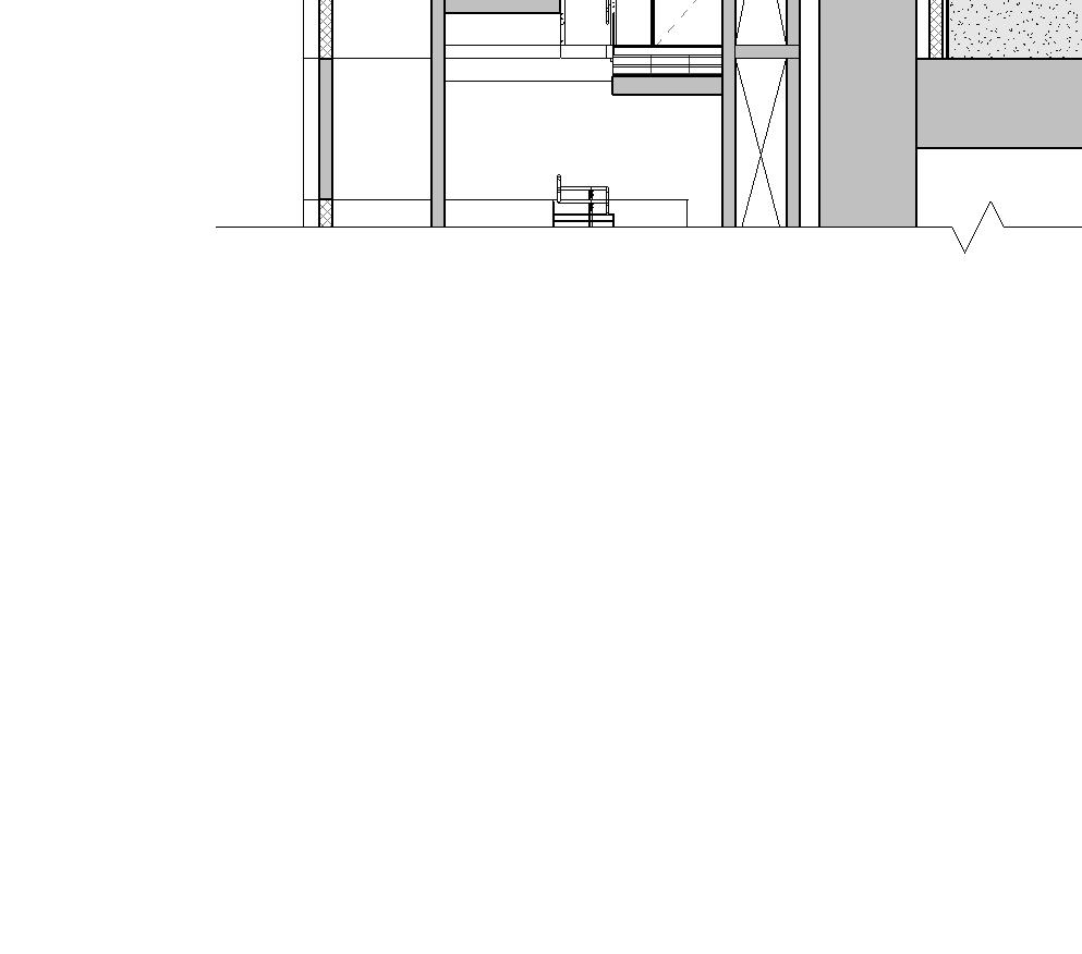
Performance Centre in Norway 2024
Academic Project
Softwares Used : Python
Grasshopper
Thinking beyond the environmental crassness of commercial buildings and their typical floor to ceiling glazing, external walls can be optimised to protect the interior from the weather outside minimising energy use. Thinking beyond the environmental crassness of commercial buildings and their typical floor to ceiling glazing, external walls can be optimised to protect the interior from the weather outside minimising energy use.
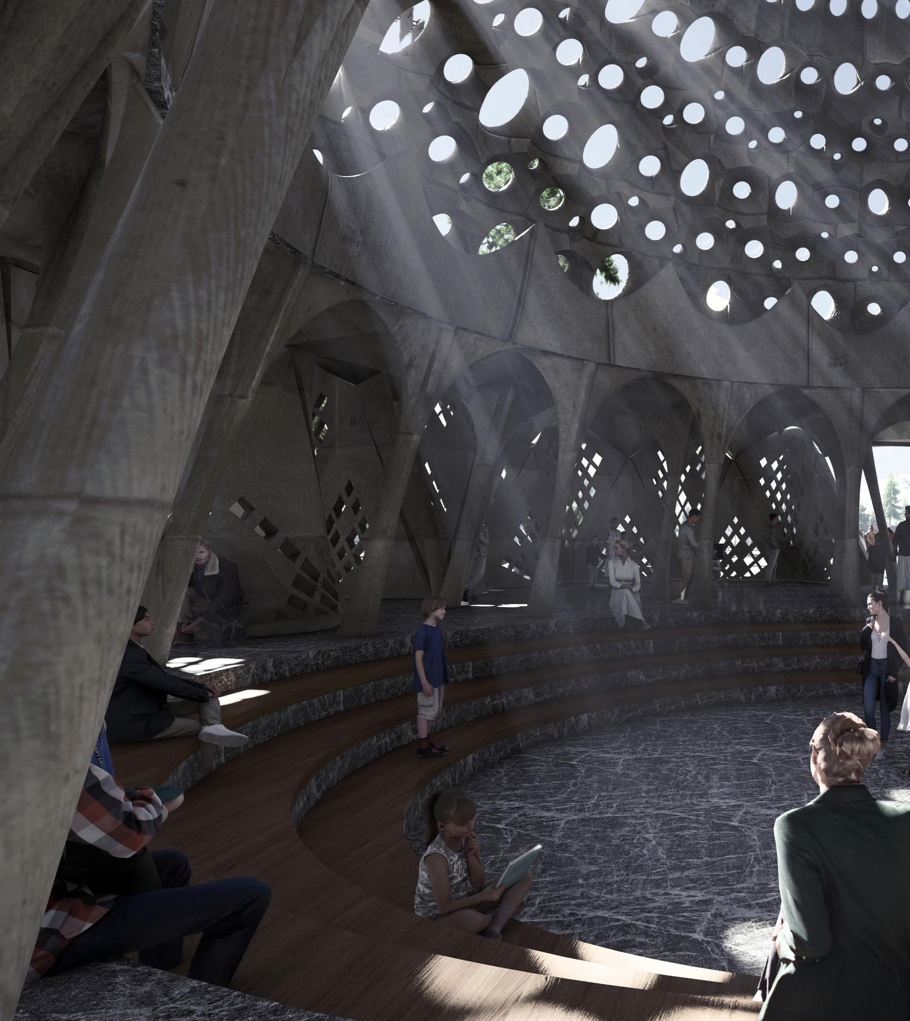
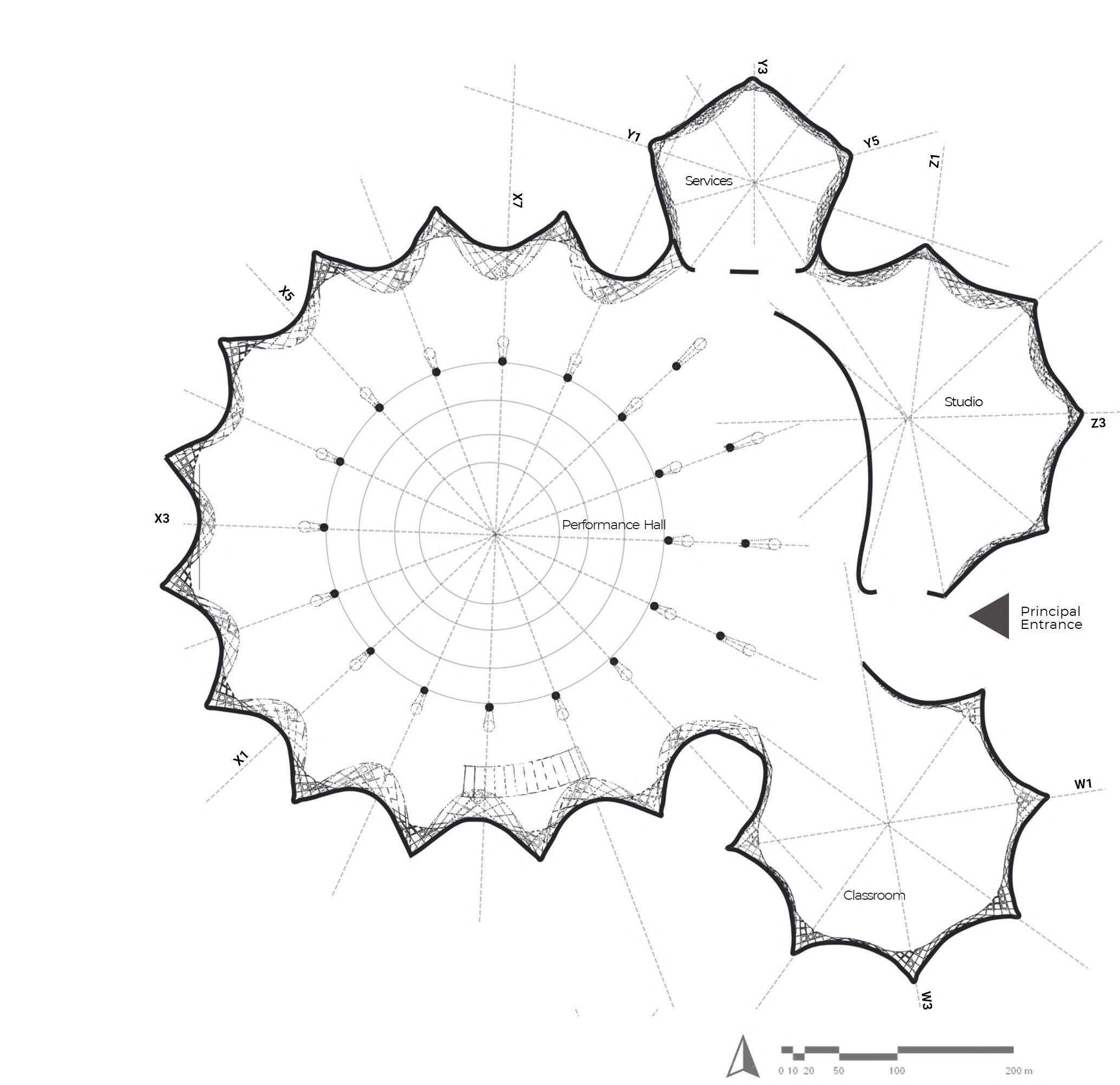
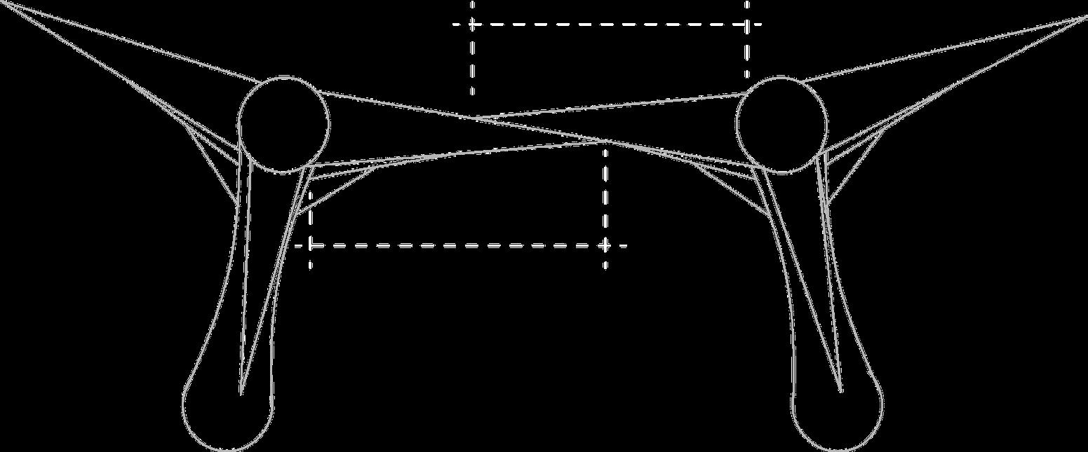
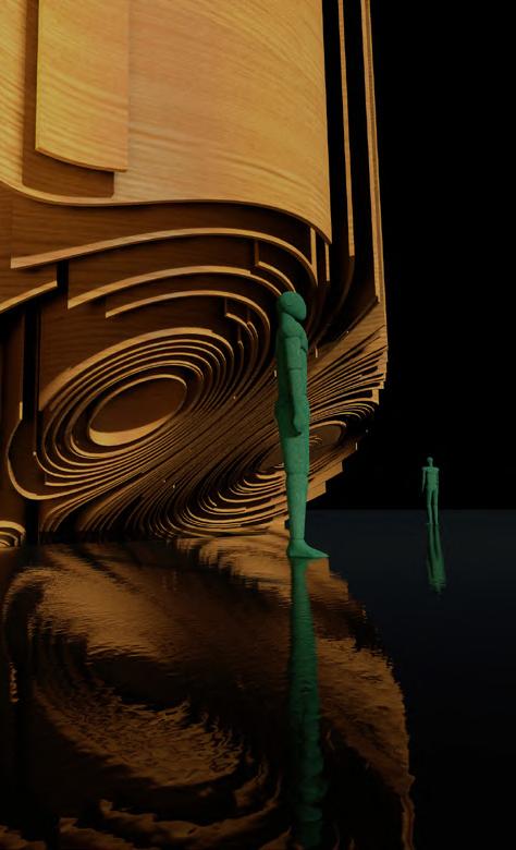
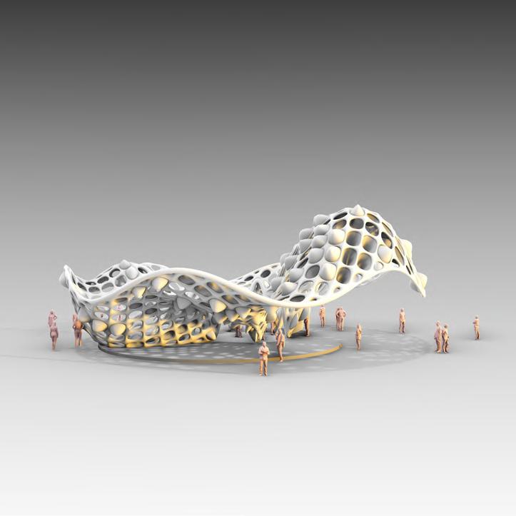
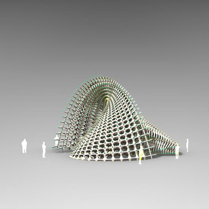
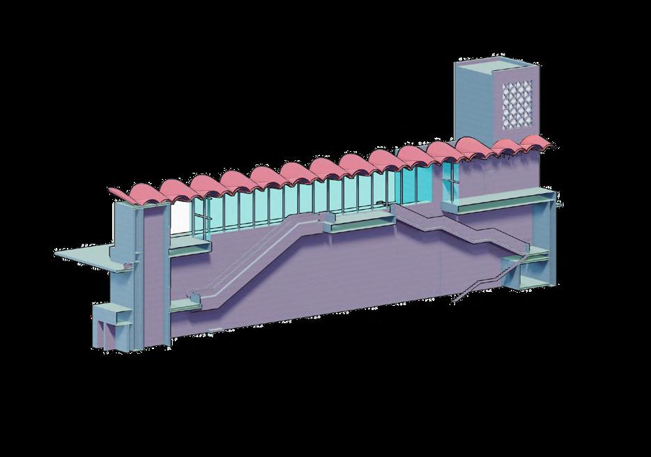
The project is a amalgamation of design principles of Antoni Gaudi and modern computational tools, to design a cultural perforamance centre in Norway. Furthermore, an additional layer of optimization will be introduced and adapted to craft the facade parametrically with maximum environmental performance criteria. Compuational optimisation was utilised ton fabricate the geometries using robotic milling and 3d printing.


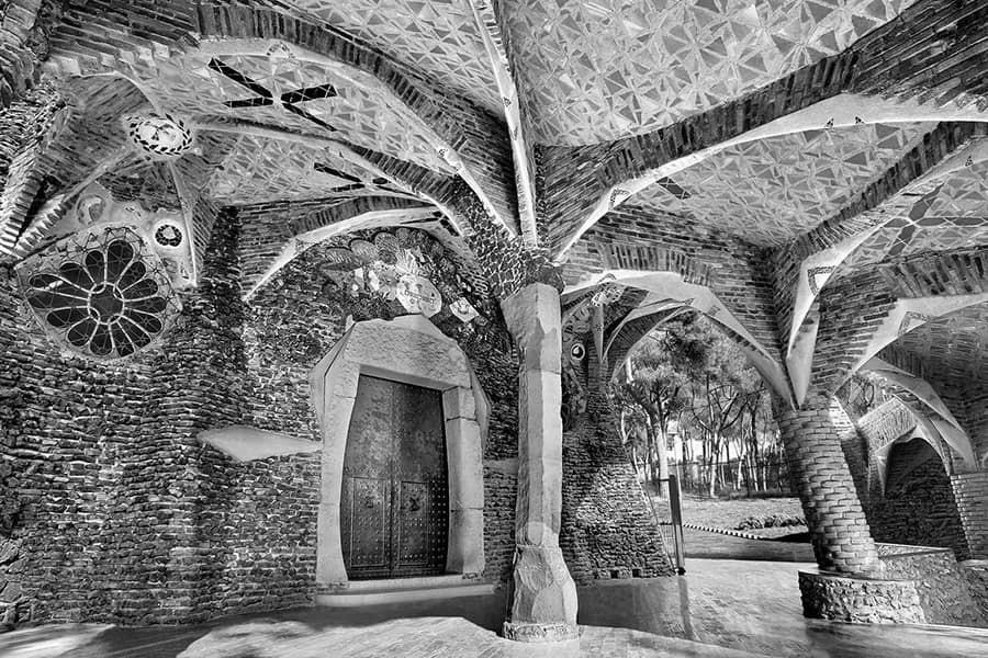
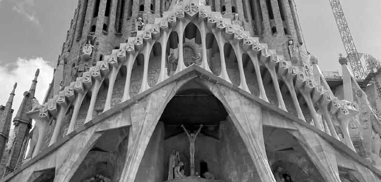
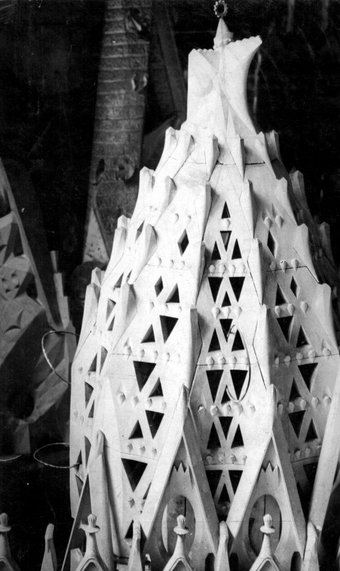
Inspiration
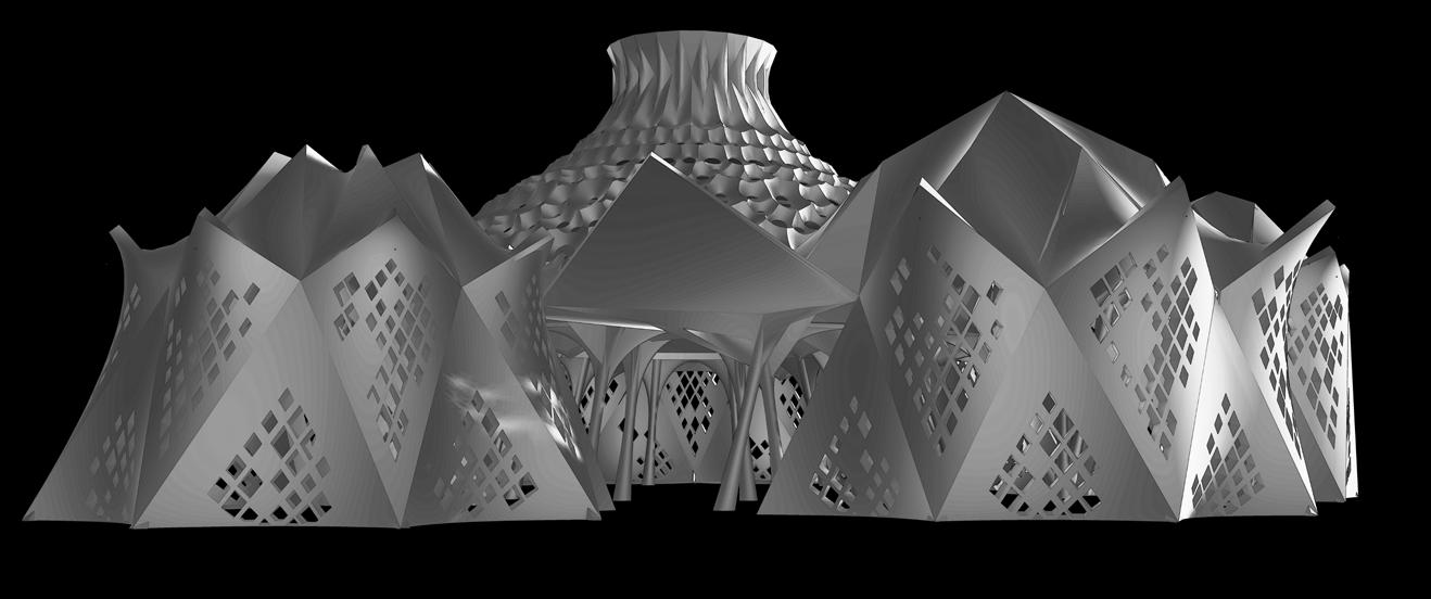
Final Proposal
Clockwise from top : Samy Tribe Tent , Sacristy Roof, Sagrada Passion Facade , Colonia Guell Entry

Crown
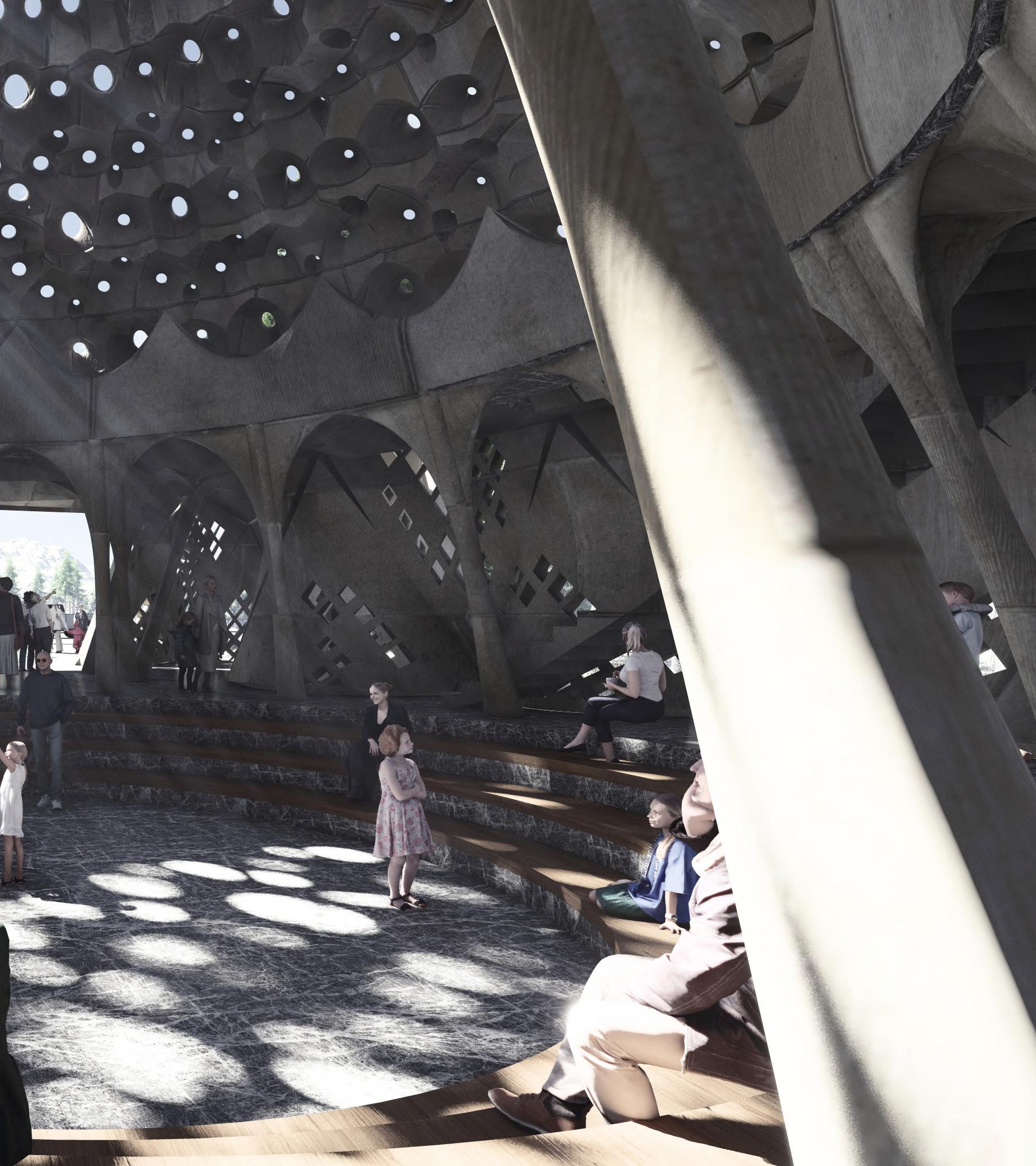
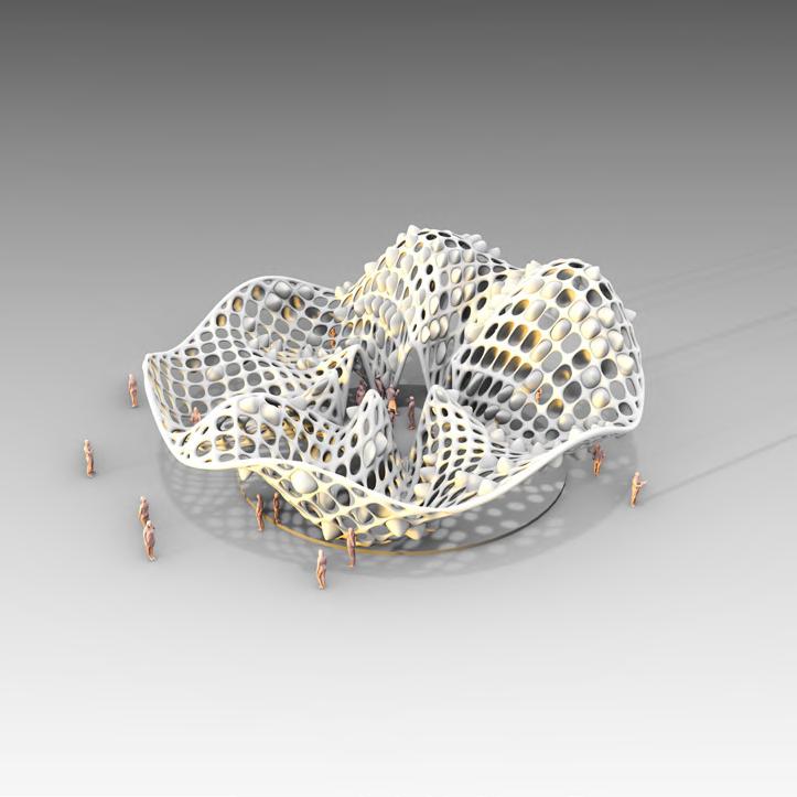
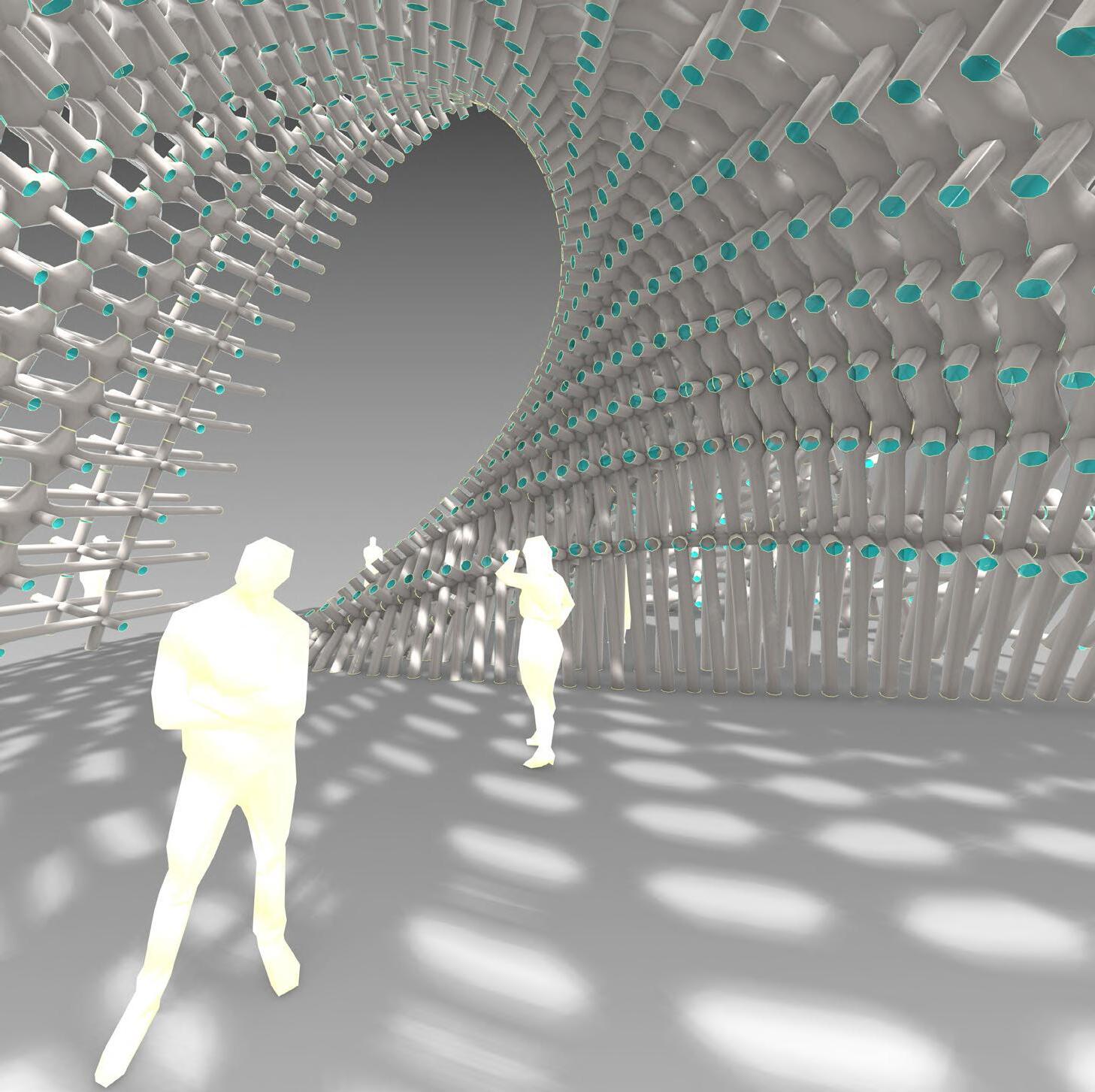
Hyperbolic Perforations for Central Dome
Sacristy Inspired Roof
Colonia Guell Like Entrance
Hyperbolic Parabolic Railings
Gaudi Like False Ceiling
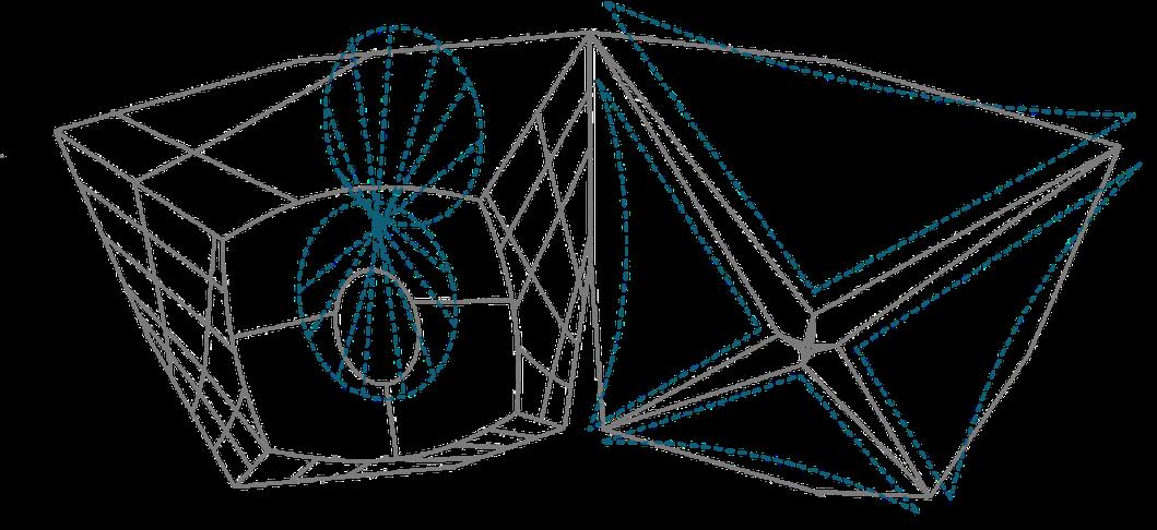
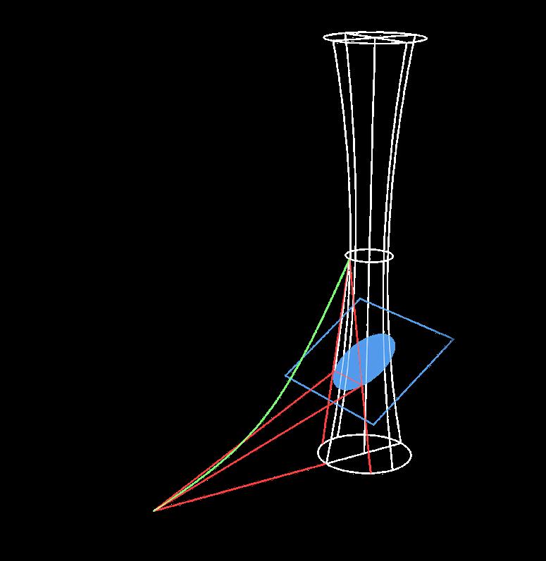
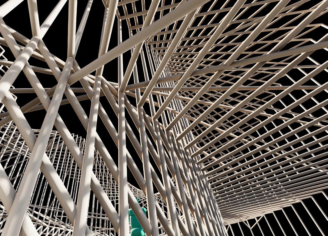
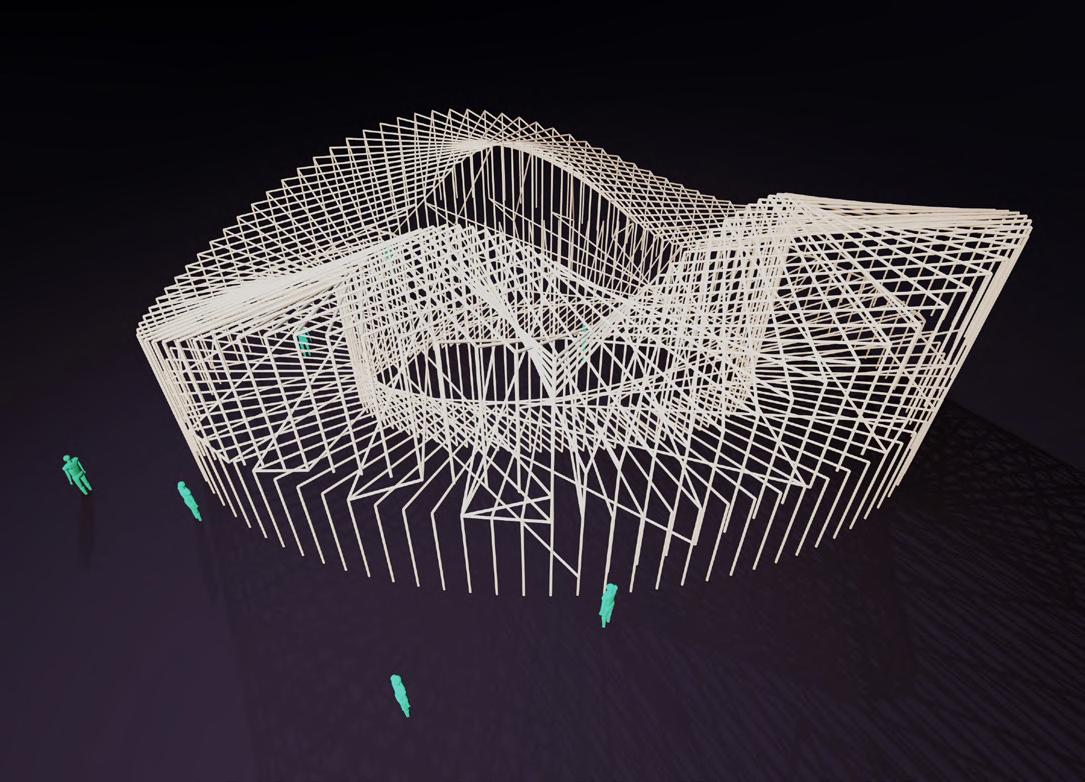
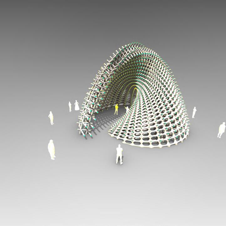
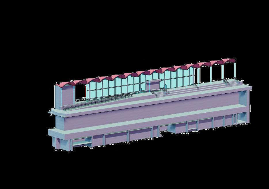
The entire form was designed compuationally using a series of design principles and mathematical logics similar to Gaudi Architecture. The primary elements are a 4 point hyperbolic paraboloid and a hyperbole in revolution. These elements are run through a set of operations and analysis and optimised using generative solving.
Perforated Hyperbolic Parabolic Walls
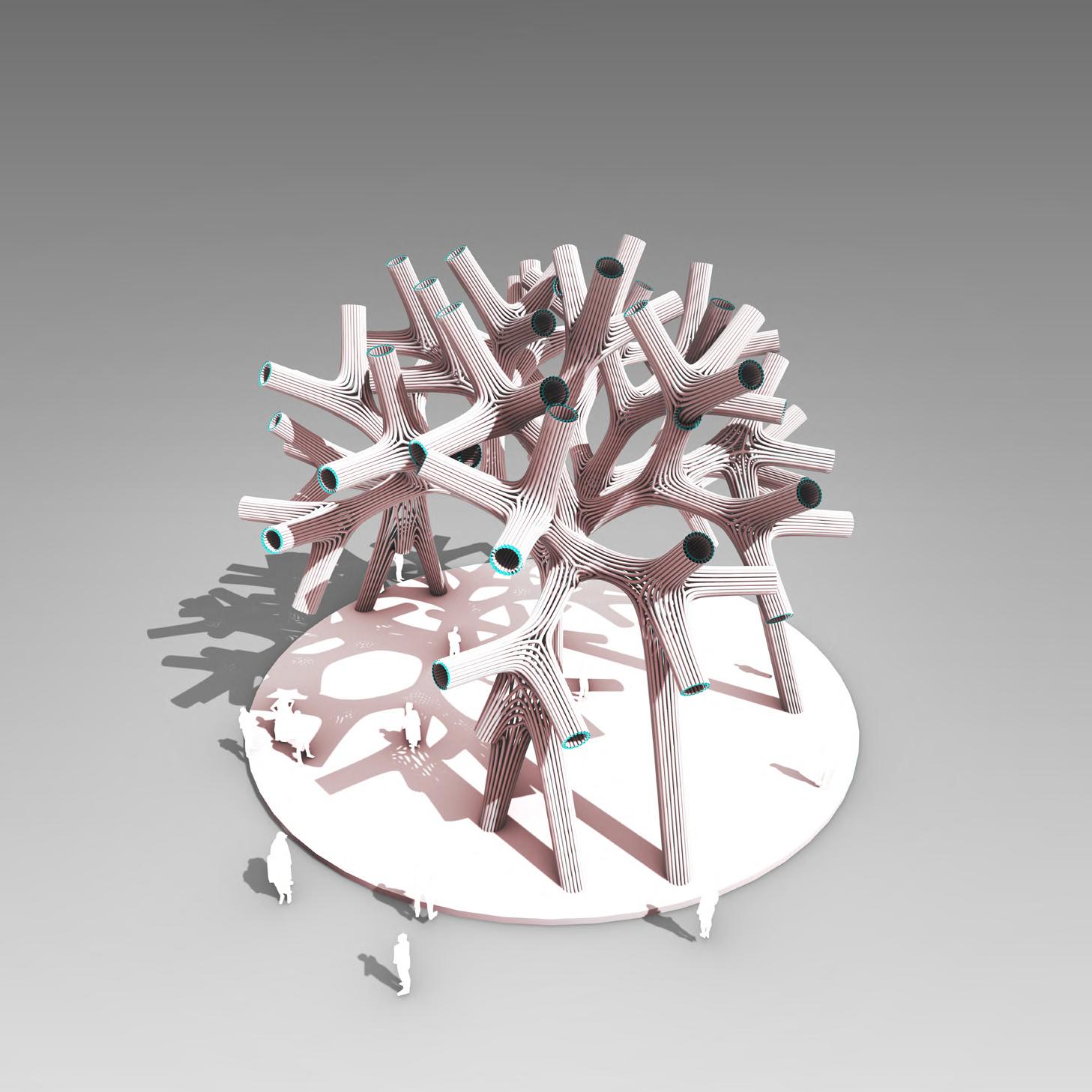
Chicken Feet Columns
Scissor Beams
Museo
Plan
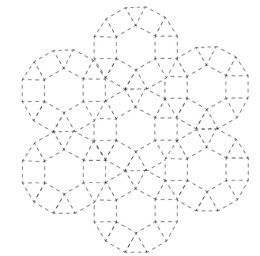
Each hyperboloid geometry has 9 parametric variables that can be configured infinitely of itself, and as a unique instance with regard to its spatial relationship with its neighbours forming the characteristic perturbations and perforations. A complex grid and variation of sizes based on analysis and optimisation strategies are used to create the central dome.
Perforation Grid
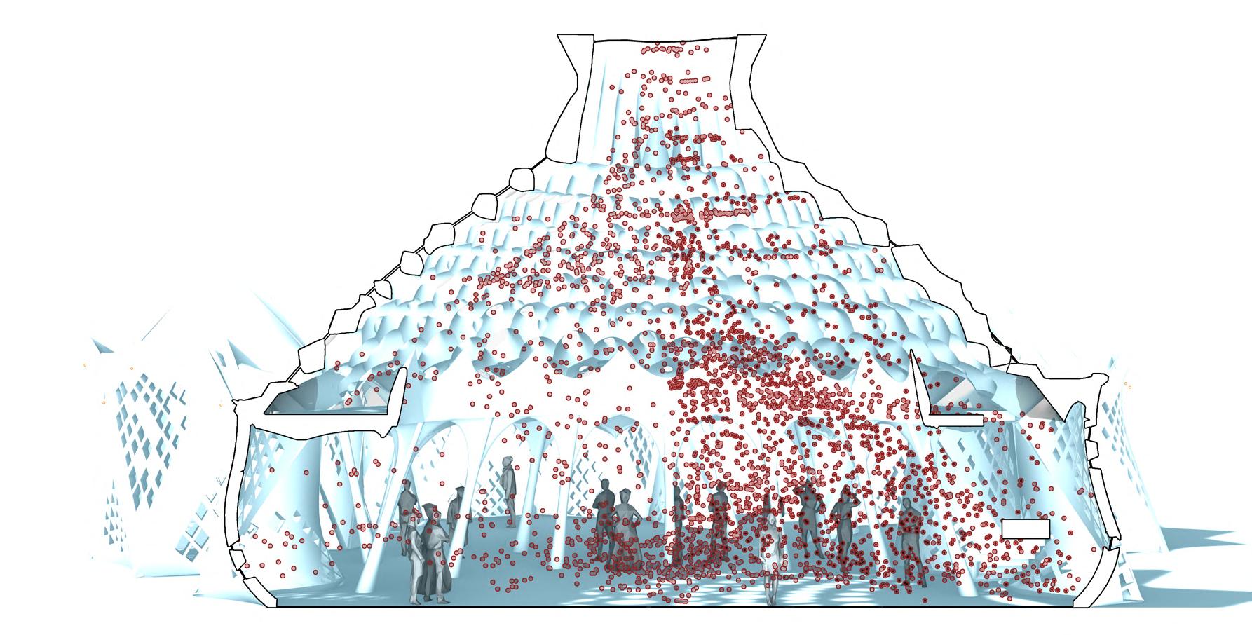
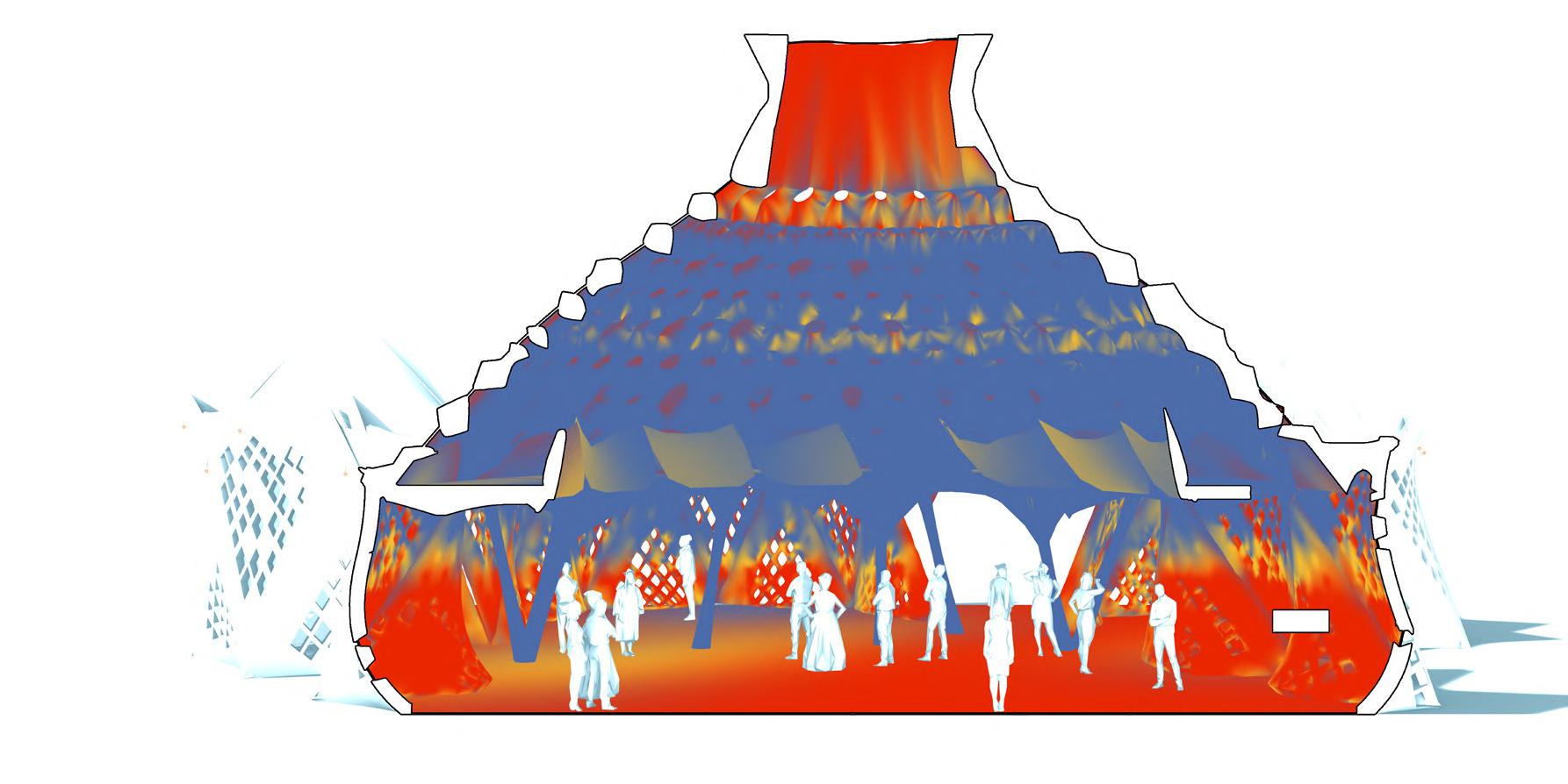
Solar Simulation
Acoustic Simulation
Dome Before Optimisation


Reflected Ceiling View
Dome After Optimisation Top View
B D X C A 0.75 *X 0.75 *X Y Column Logic Framing Logic
Ceiling Logic
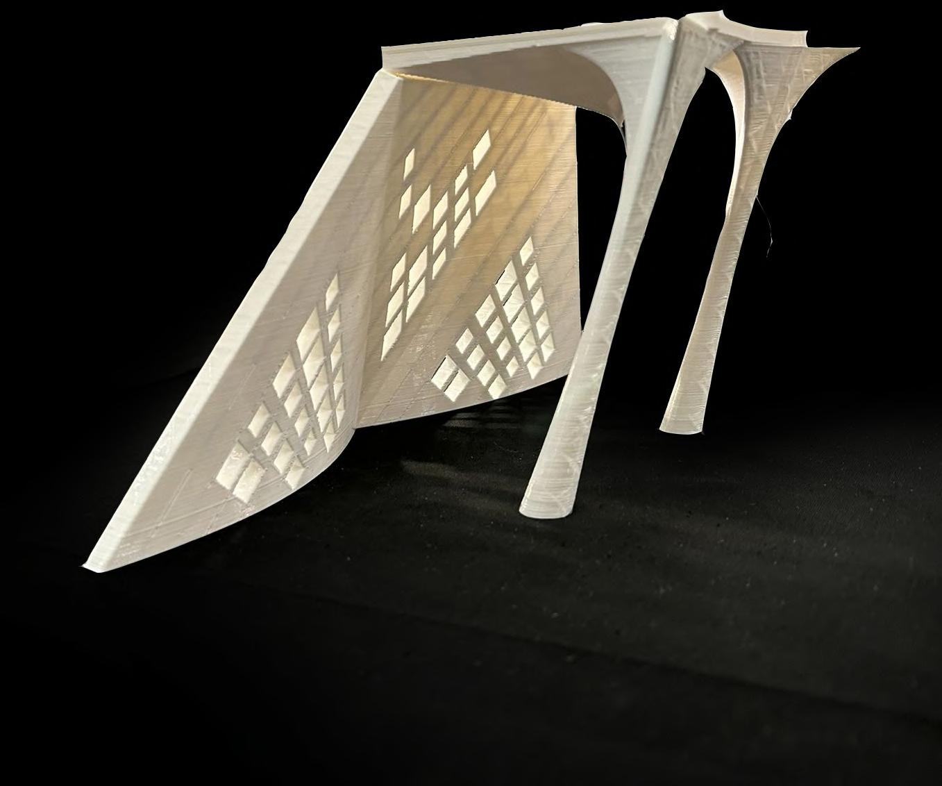
3D Printed Section Prototype
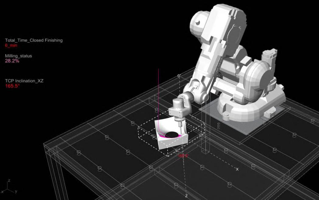
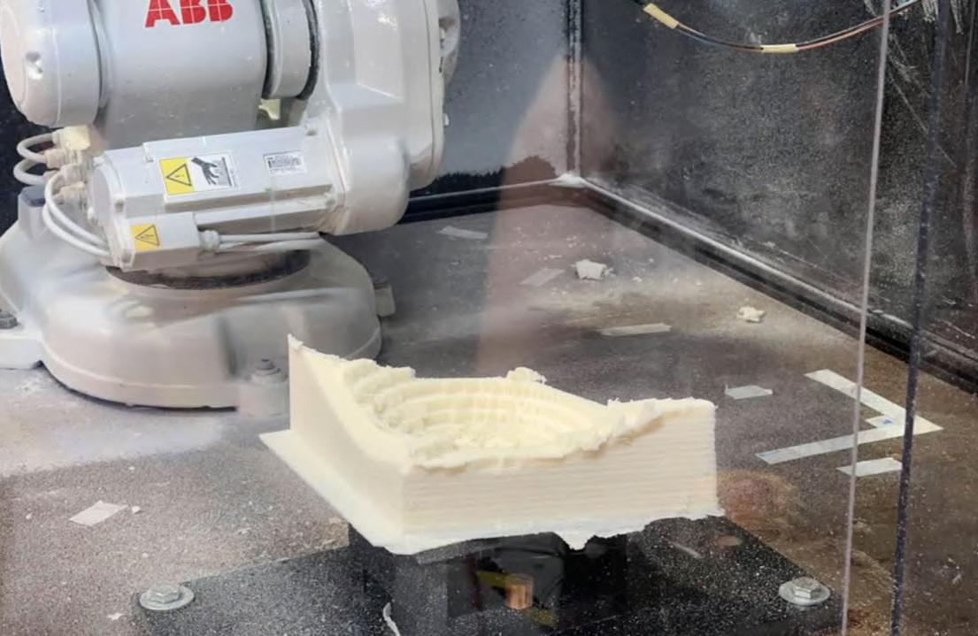
Robotic Simulation and Process
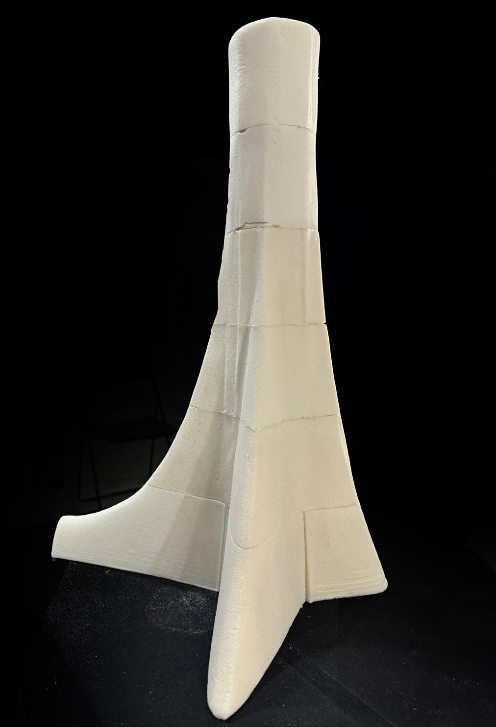
Milled Column Prototype
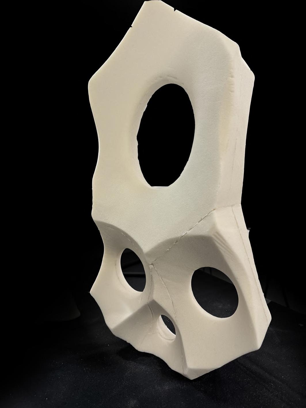
Milled Perforation Prototype
For Prototyping the geometry is bifurated and optimised to reduce material wastage and print time. This is done by splitting the geometry in pieces and testing for various orientations for the geometry and End effector.
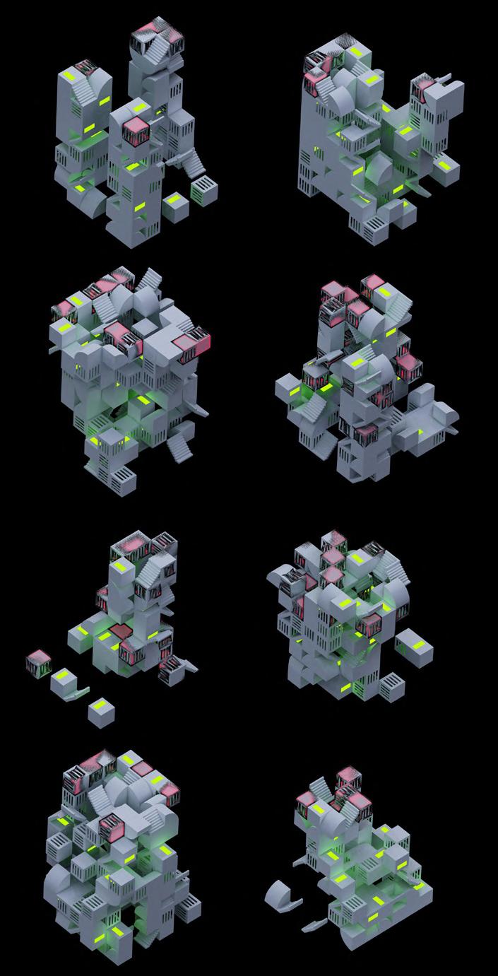
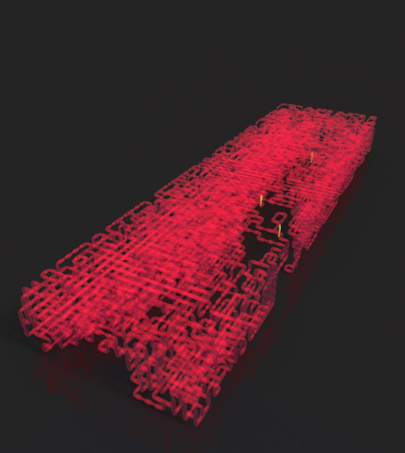
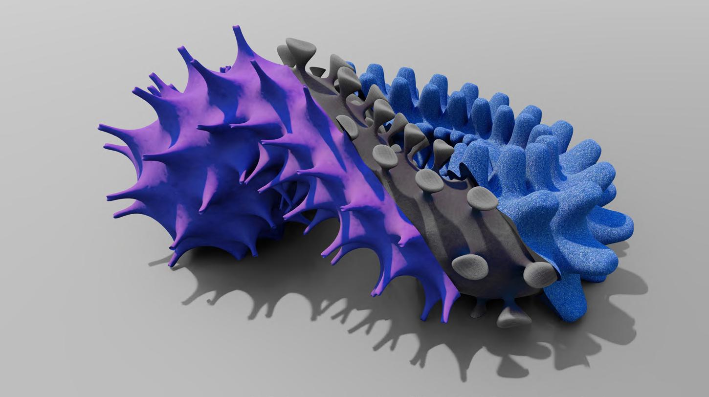
AUTONOMOUS POLYMORPHIC EXPLORATIONS
Experimental Design Initiative
2021-Present
APE is a space to ask all the relevant and irrelevant questions, for the answers to be found.
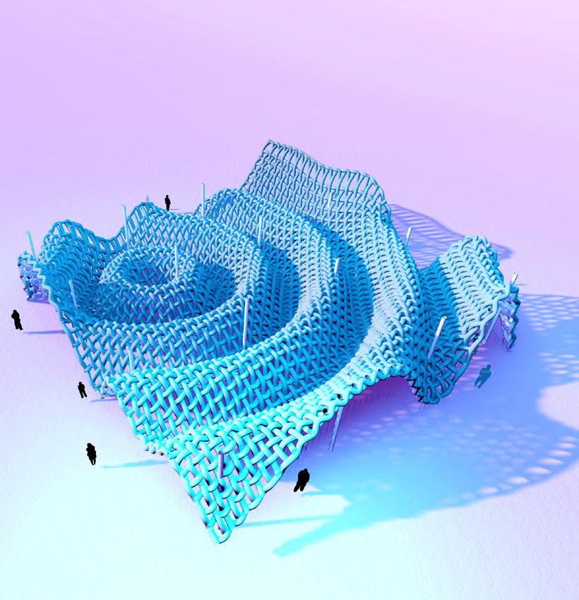
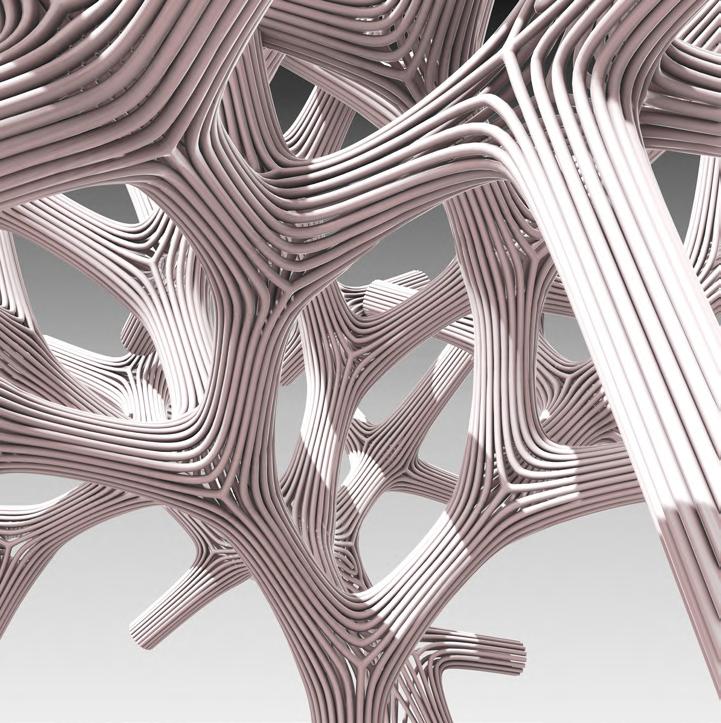
Can structures grow and not build?
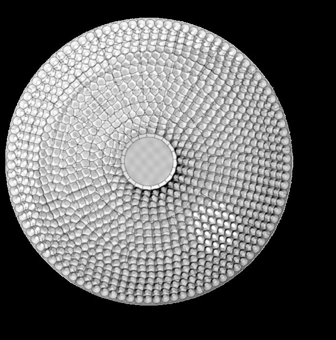
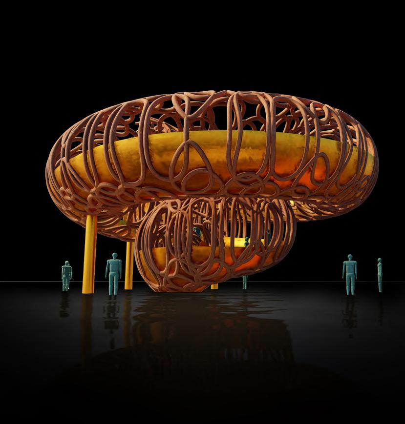
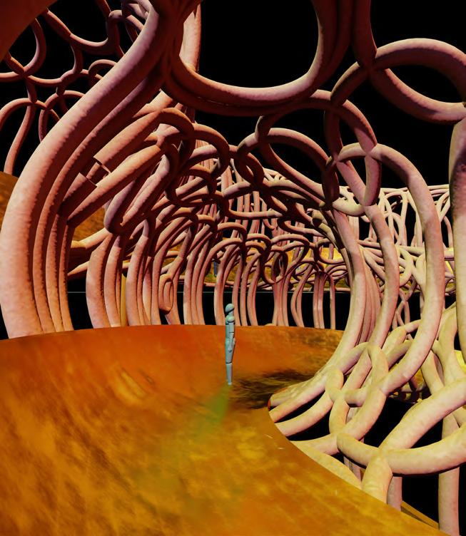
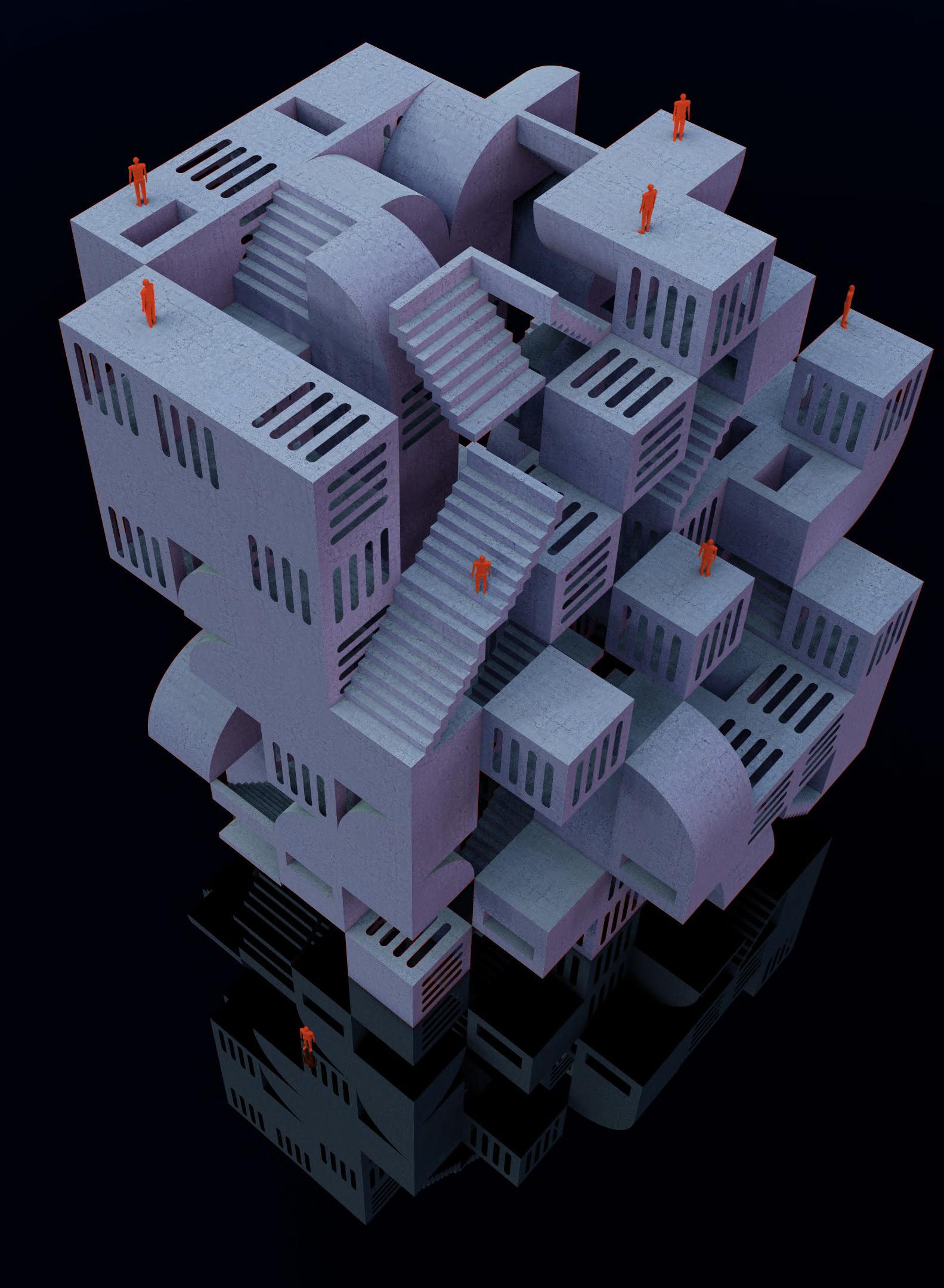
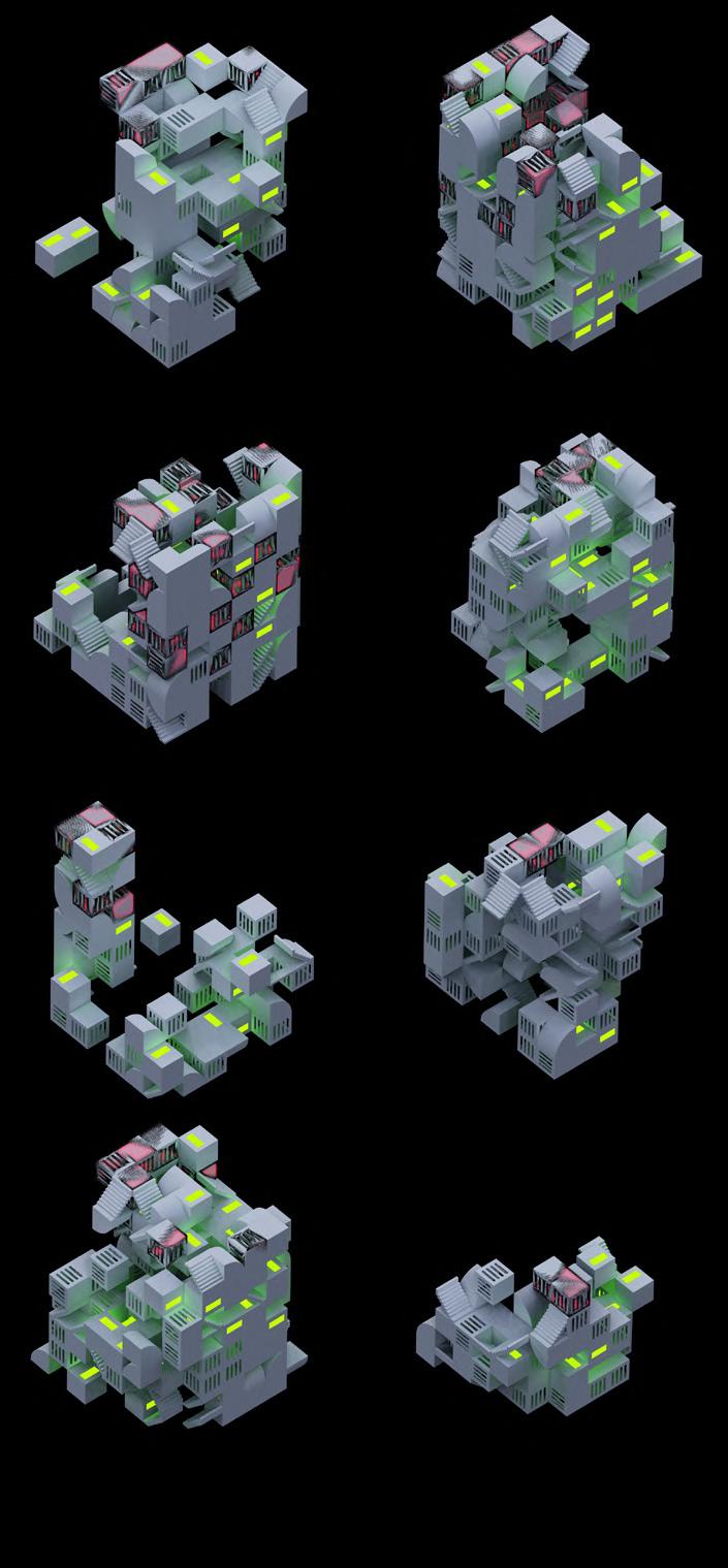
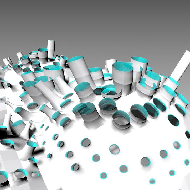
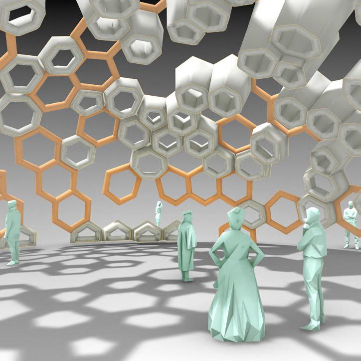
It aims to explore experimental design theories and its relevance in real world, fuelled by a deep understanding of Data driven design. The main aim is to explore on a theoretical level, how architecture can accommodate various roles and functions and acquire various forms i.e., be Polymorphic to respond to multitude of spatial and functional needs seamlessly, adapt with broader performance criteria, respond to climatic stimuli.
The work of APE is strictly driven by data. I try to use existing data and values and compute them through a layers of operations to find a desired result. The works is many a times inspired by works of biologists, mathematicians and other field professionals.
There are seldom some degrees of randomness in the design. But as Maya Lin said: “I do not think you can find a reason for everything you make.“


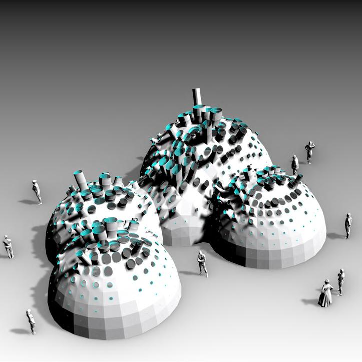
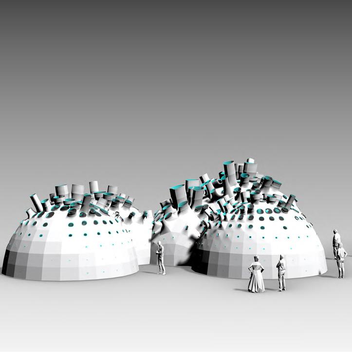
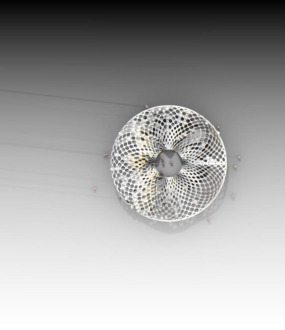
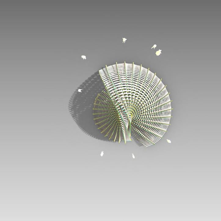
Is that a golden spiral curve?


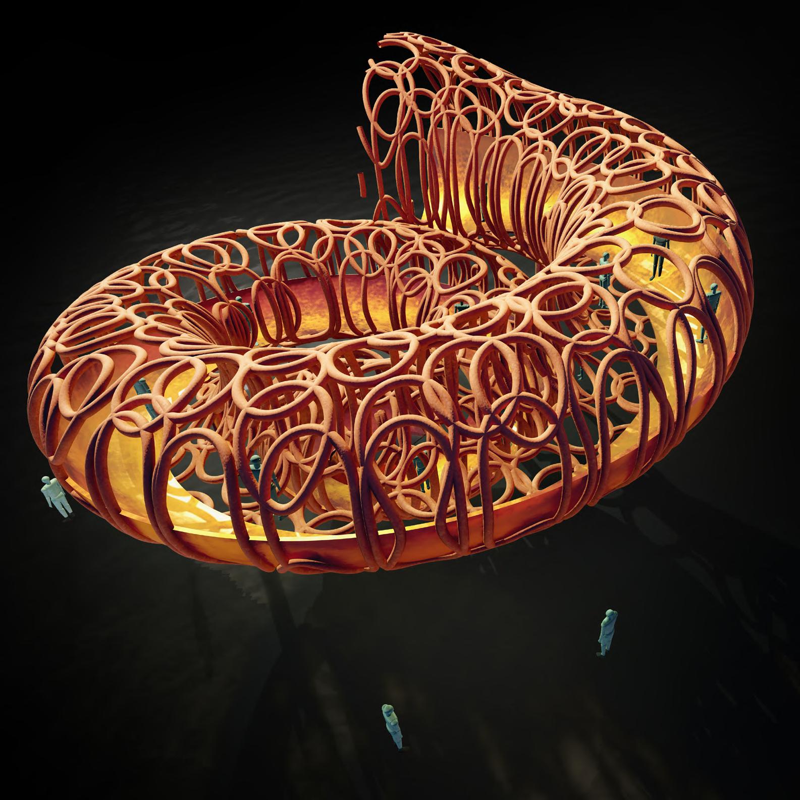
Now we are getting closer to buildings.

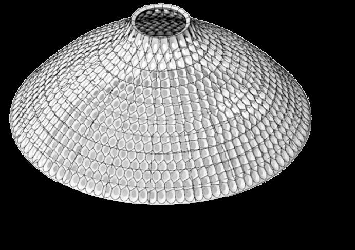
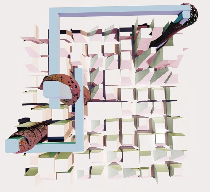
What are those?
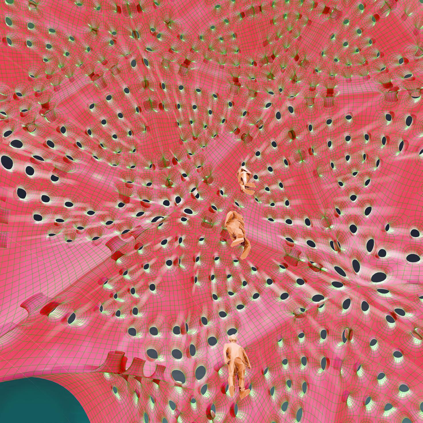
Thumb prints?
Actually they are magnetic fields.
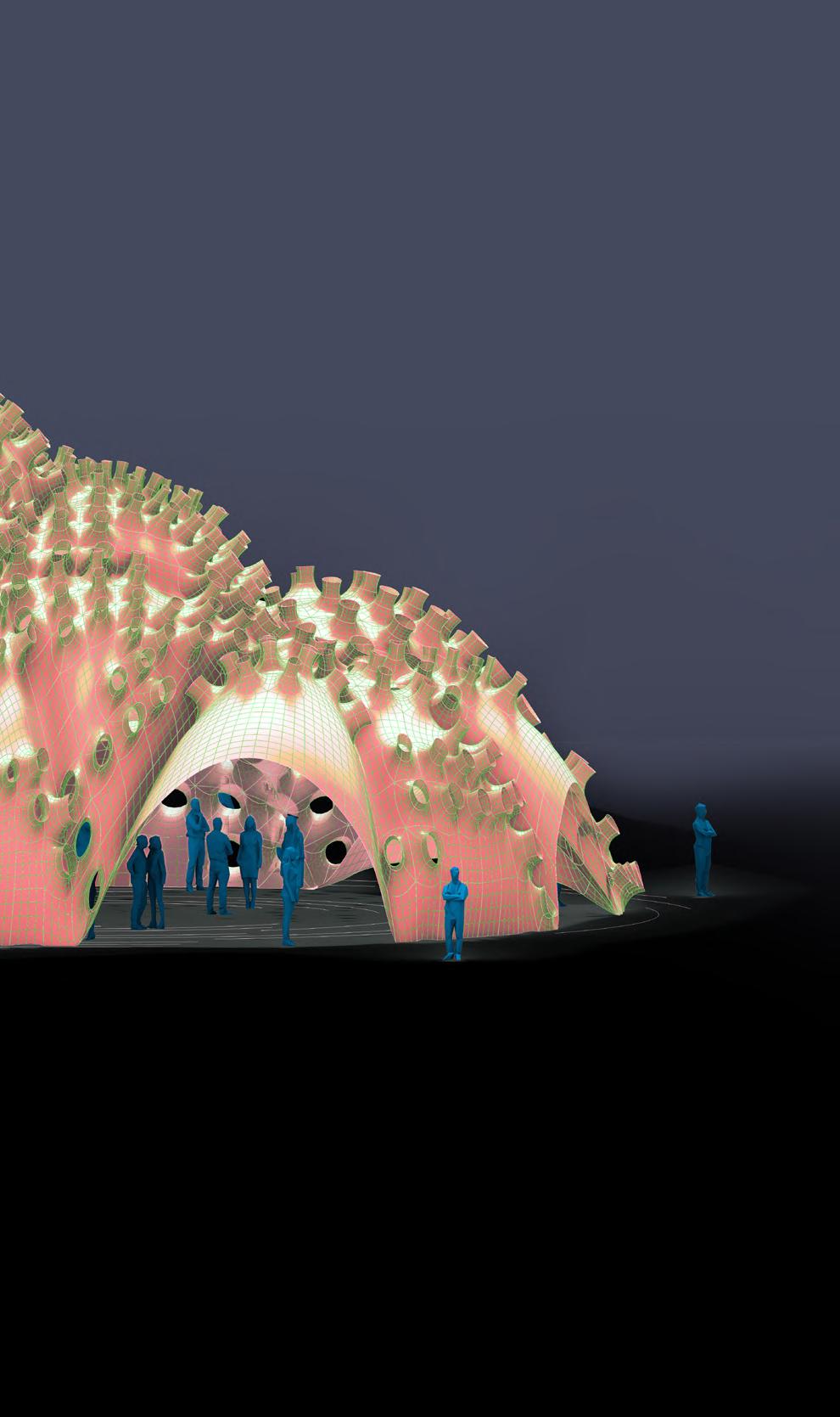
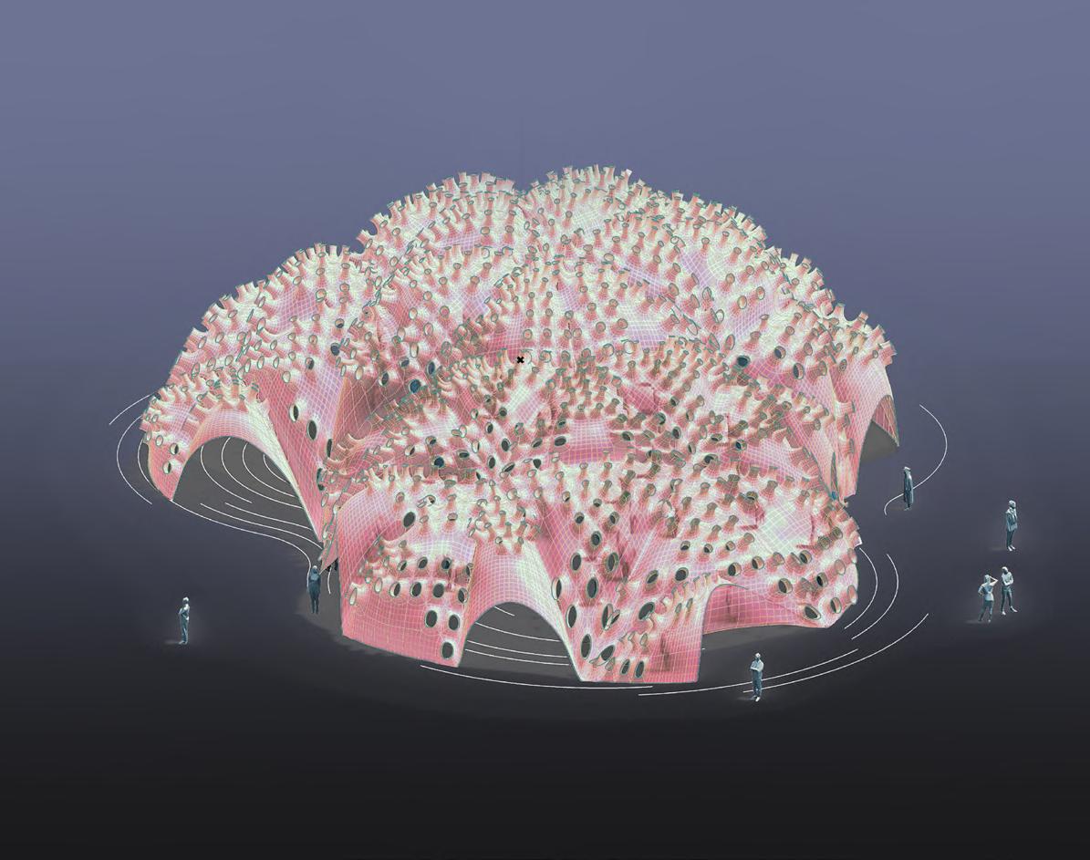
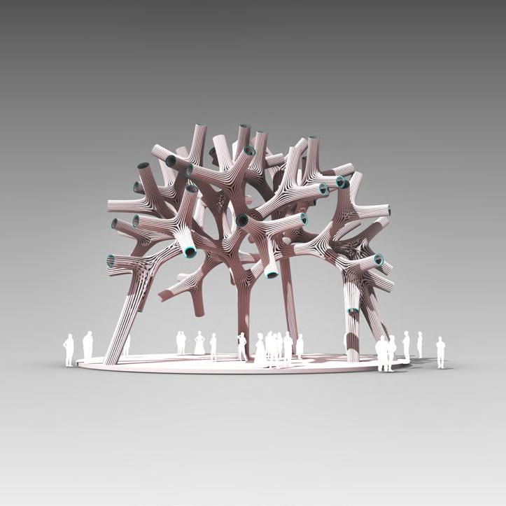
A building with a facade cloak with varying size of openings. How ingenious. And those huge sky bridges.
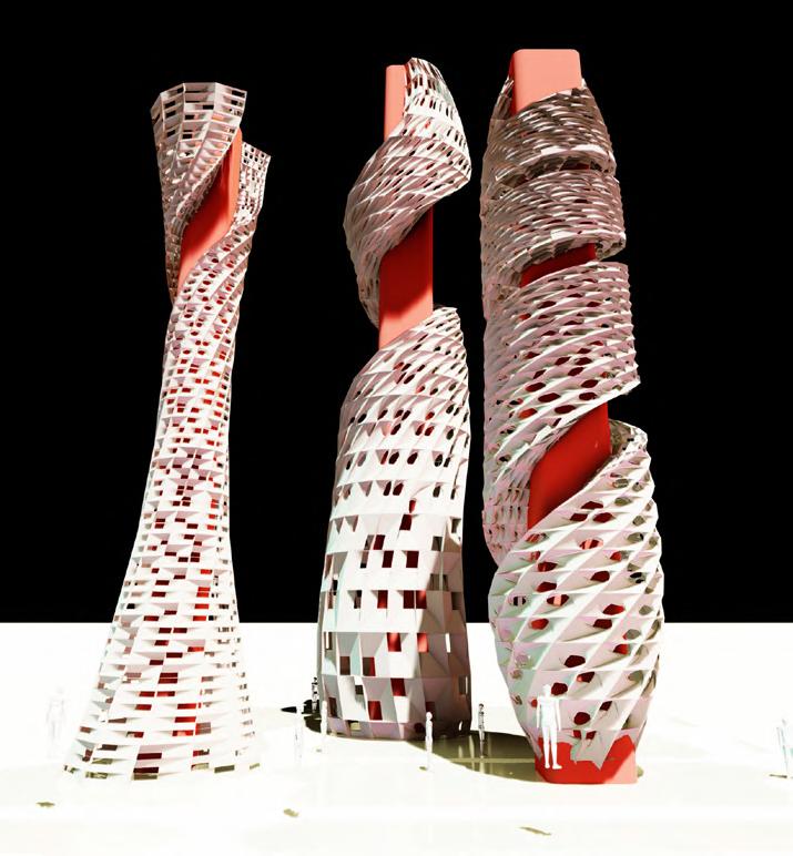
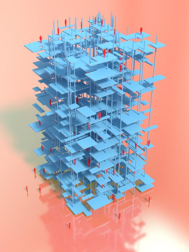
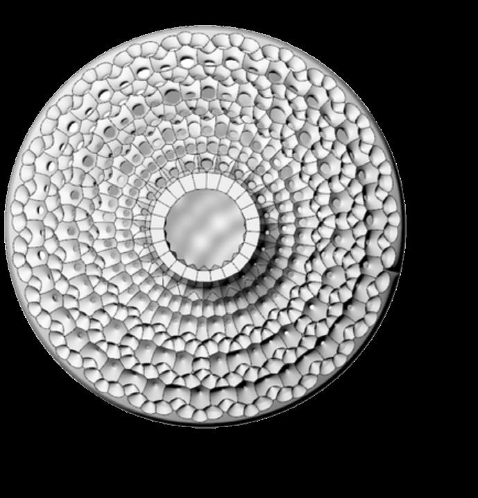
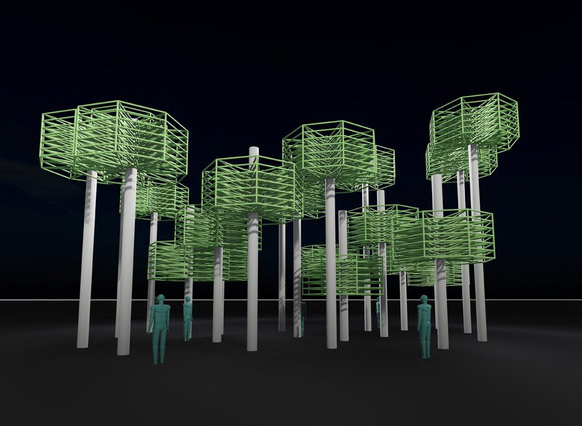
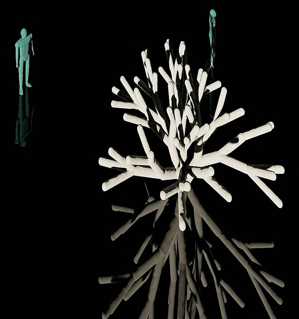
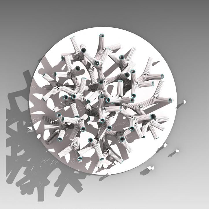
Growing Towers. They seem to inspired by trees. Like the Lindenmayer systems.

Did you know the old computer game Mine sweeper was also based on growth systems.
Can we make buildings with facades like this. Where opening varies by time of day and direction of sun throughout the year. This can control facade surface area and also heat loss parameters. So many Posssibiltes!!
It used an algorithm that automated plots based on neighboring number of plots. Cellular Automation. Imagine its possibilities with buildings and urban systems.

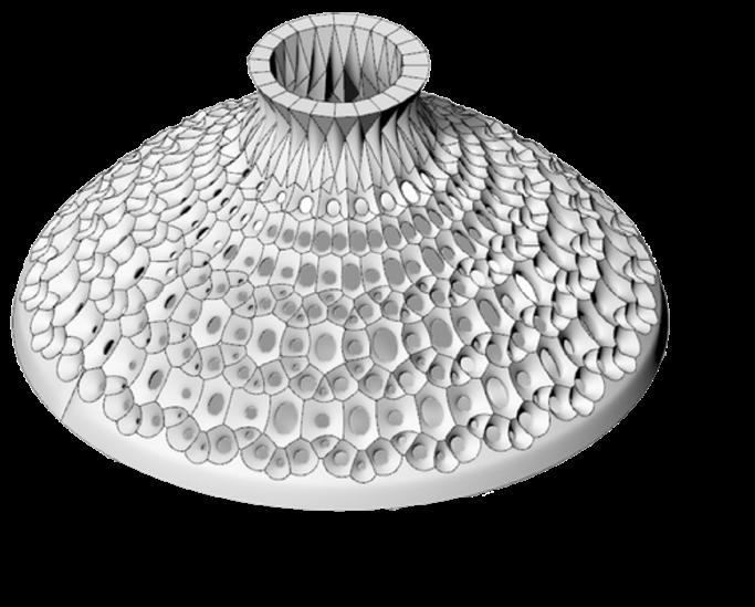
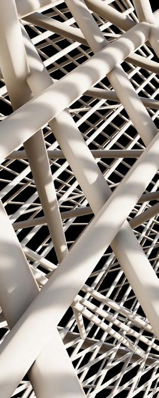
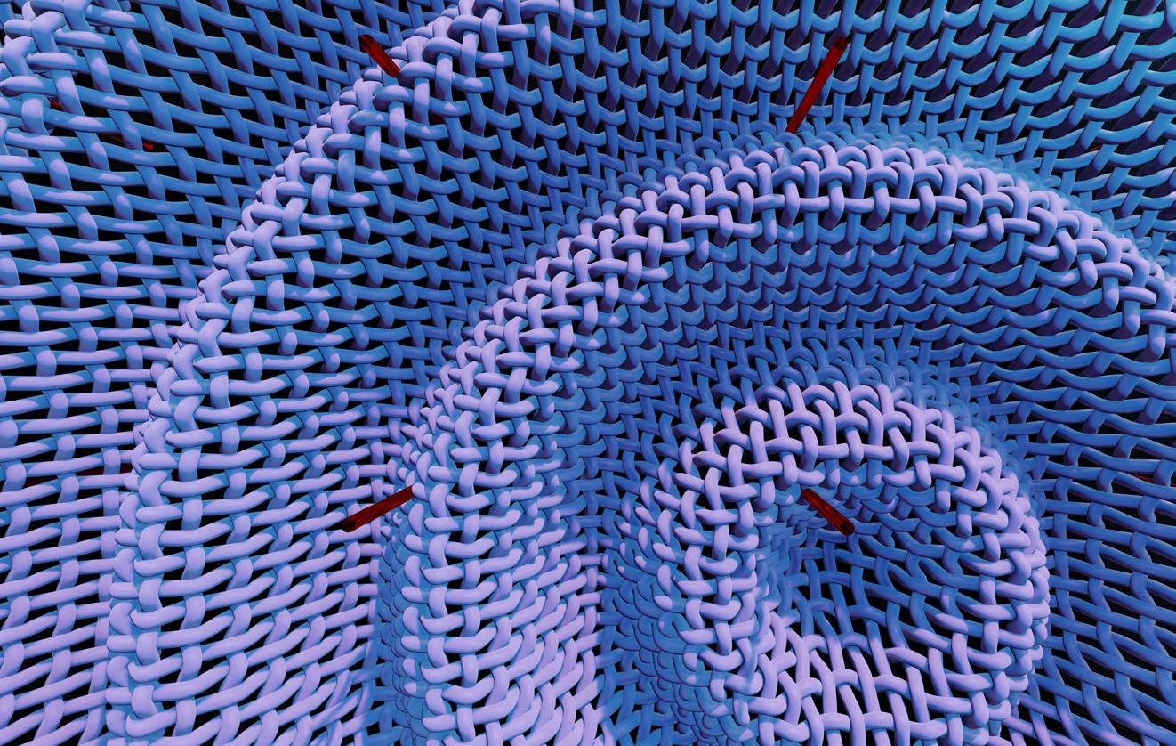
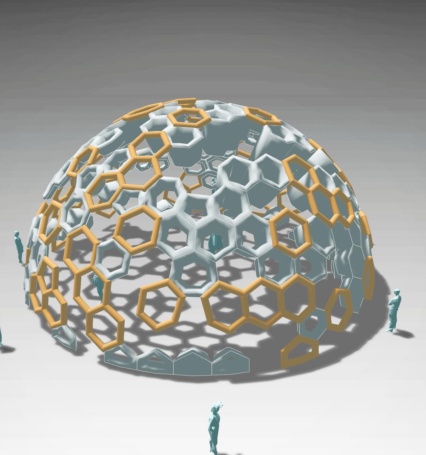
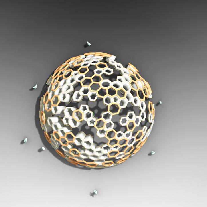
Pavllions of Pipes??
Aggregations !!
Genetic optimisations !!
CODIN PARAMETRIC
2023-present
Associated with Codin Parametric
As part of Codin Parametric, a place where architects, designers, and enthusiasts come together to learn, share, and create, we tend to creae simple scripts dn design for showcasing and eductaing. It’s our way of manifesting Codin’s aspiration to make design innovation accessible by offering a platform that fuels creativity, facilitates skill growth, and bridges the gap between design enthusiasts and experts.


ARCHITECT AND BIM DESIGNER
2020 | 23
Design + Build Projects
After my Bachelors, I worked on various types of projects; big and small -residences, offices, parks and what not; and in different roles, as project lead, team lead sometimes as a team member and sometimes as the BIM manager. Working initially in a boutique studio and then in an International office like BDP, I had a chance to learn a lot...
ASSEMBLIES
Dhaka Metro Line 5, Bangladesh 2022-2023
Worked with Building Design Partnership Project Type : Transport Softwares Used : Revit
This included the design detailing of 9 Metro stations in Dhaka in close collaboration with BDP Manchester Studio.
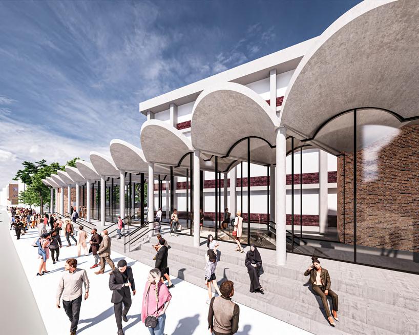
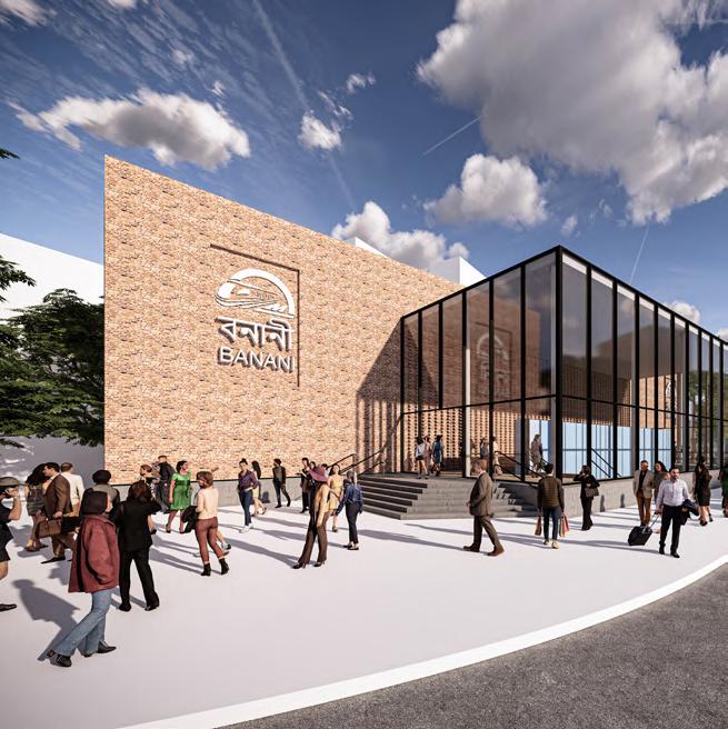
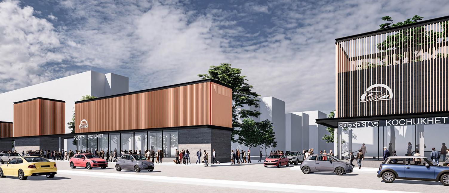
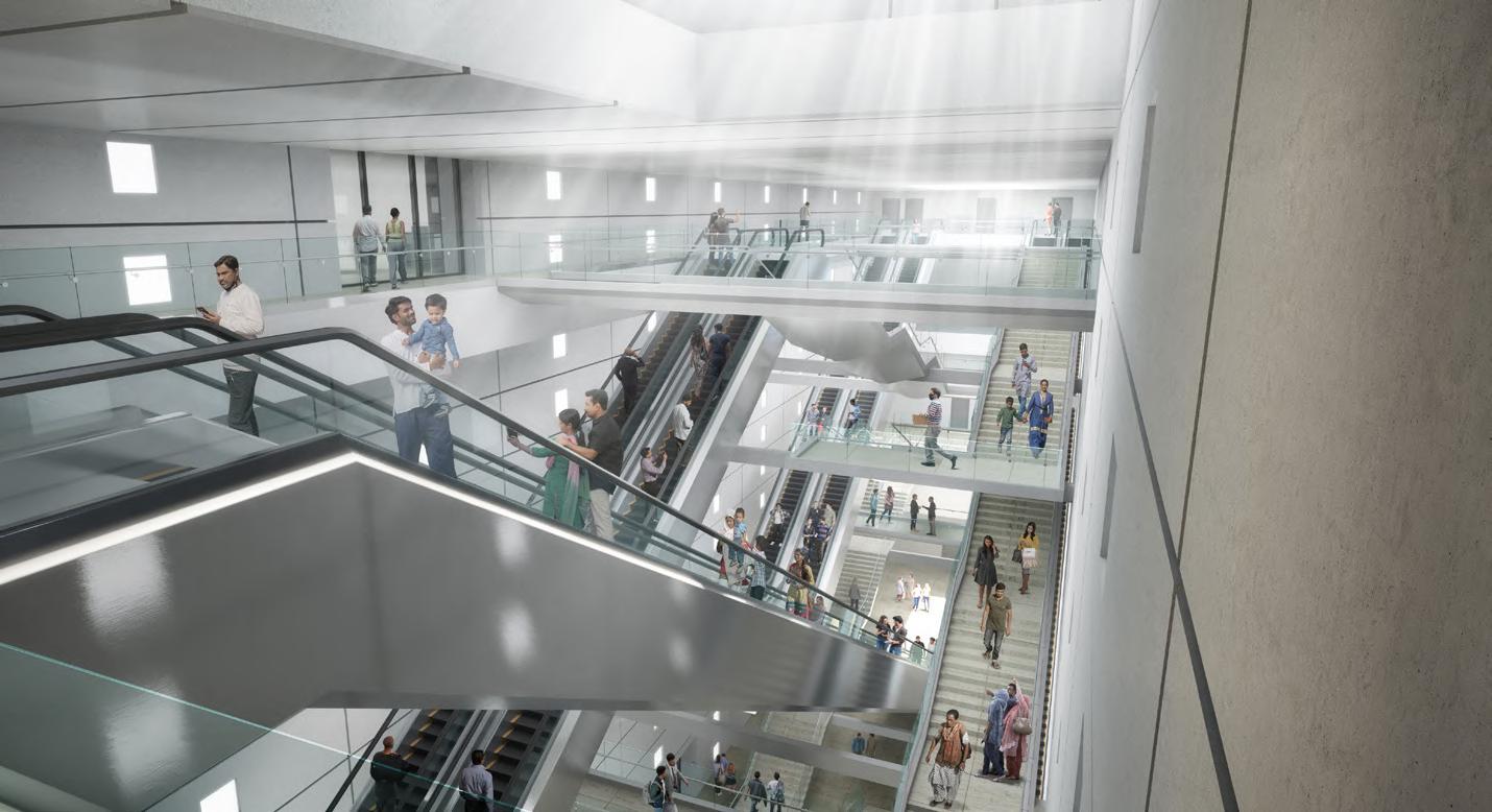
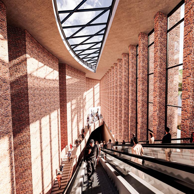
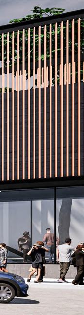
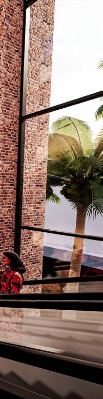
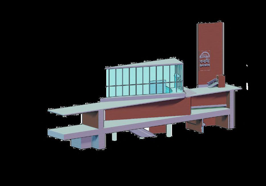
Designing nine underground stations for Dhaka Metro Line 5, which will cross the heart of the city from west to east poses various challenges. Firstly, due to the dense urban fabric and limited powers of MFCA, the metro stations are designed as subterranean structures. This poses further issues in Dhaka which is a highly flood-prone region. There is an intense focus on the design of these details, and they will have to incorporate these challenges. Each station has a variety of material palettes, with entry structures being designed with materials like Brick, GRC, Glass and such like; to present a modern image of the city. yet also connect to the traditions.
 Mirpur 14
Banani
Kochuket
Mirpur 14
Banani
Kochuket
10
Mirpur
2
Gulshan

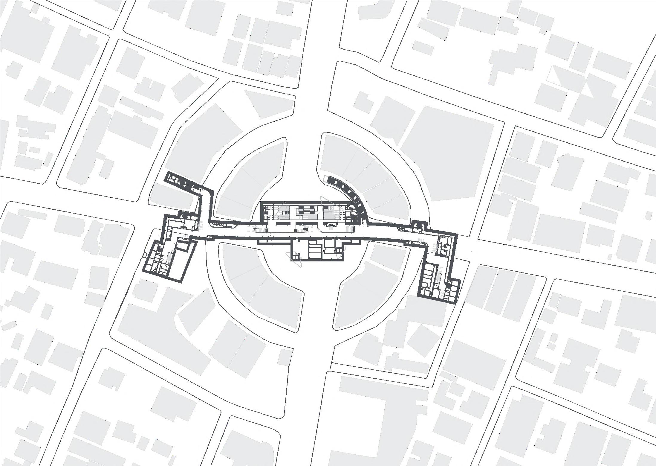
Station Site Plan, Gulshan 2 Station
Station Concourse Plan, Gulshan
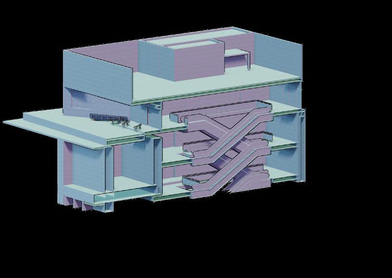
Gulshan is a special case even among the 9 stations as it is the only station in this line which has platforms stacked on op of each other. This is due to space constraint in the main square. The concourse descends to a 40 m tall box below the ground to the lowest platform and plant rooms. This concourse is lit by a series of lightwells and ventilation shafts that come out on the ground as glass 4 central glass cores are connected by a circular Halo Screen display system around the public square on ground floor.
CORE EXIT
VENT CORE EXIT 2 EXIT 3 VENT CORE LIGHT CORE HALO LIGHT CORE
1
S12-16 S12-08 S12-09 S12-11 S12-12 S12-14 S12-19 S12-15 S12-13 S12-07 S12-A S12-F S12-H S12-24 S12-23 S12-21 S12-22 S12-20 S12-E S12-B S12-18 S12-C S12-10 S12-17 S12-D S12-04 S12-03 S12-06 S12-05 S12-02 S12-01 S12-E1-C S12-E1-A S12-E3-03 S12-E3-02 S12-E3-A S12-G S12-E3-04 S12-E4-01 S12-E4-03 S12-E1-B S12-E1-D S12-E2-02 S12-E2-03 S12-E2-04 S12-E2-05 S12-E2-06 S12-E3-01 S12-E3-F S12-E3-E S12-E3-D S12-E3-C S12-E3-B S12-E4-E S12-E4-D S12-E4-C S12-E4-B S12-E4-A S12-E4-02 S12-E4-04 S12-25 S12-26 S12-27 S12-E2-B S12-E2-A Color Type Mark Description Flooring Finish Legend ColorType Mark Description Flooring Finish Legend F2 F4 F6 F7 Honed Granite Flooring -Colour 1 F1 F3 Anti-Skid Ceramic Floor Tile with Membrane W.P. F8 Honed Granite Flooring -Colour 2 F9 Honed Granite Flooring -Colour 3 F5 F10 Granite on Stairs-Colour 3 F11 Tactile Flooring Cementitious Water Proofing (CW-1) Membrane Water Proofing (WP-1) F13 Bare Concrete ColorType Mark Description Flooring Finish Legend F14 Raised Access Floor (H-450MM) F15 Raised Access Floor (H-200MM) F16 Ceramic Floor Tiles with Cementitious W.P. Vitrified Floor Tiles Anti-Skid Vitrified Floor Tile with Cementitious W.P. Screed with Floor Hardener Screed with Floor Hardener with Cementitious W.P. F12 Concrete Pavers F17 F18 Anti-Skid Ceramic Floor Tile Polished Granite Flooring Screed with Floor Hardener with Membrane W.P. F19 Anti-Dust Paint on Bare Concrete F20 Anti-Skid Vitrified Tiles on Stairs @ A1 DRAWING TITLE SCALE DRAWING No @ A3 PROJECT TITLE CLIENT DHAKA MASS RAPID TRANSIT DEVELOPMENT PROJECT (LINE 5): NORTHERN ROUTE JICA LOAN NO. BD -P101 Dhaka Mass Transit Company Limited (DMTCL) Dhaka, Bangladesh Consultants Association) Ltd Consultants Global Co., Ltd Corporation Ltd Pvt, Ltd Engineers International Design Consultants Ltd CONTRACT TITLE DESCRIPTION DATE REV PREPARED BY APPROVED BY CHECKED BY DESCRIPTION DATE REV PROVIDED BY APPROVED BY CHECKED BY 1:1000 B1-CONCOURSE REFERENCE FLOOR PLAN FLOOR FINISHES S12 -GULSHAN 2 1:2000 YJ PMJ KK DML5N-CP06-DD-S12-STA-10201 1 1000 B1 -Concourse Floor Flooring Reference Plan 1 RESPONSIBILITY FOR ANY USE MADE OF THIS PREPARED AND ISSUED. BROUGH TO THE ATTENTION OF BUILDING FOLLOWING BEFORE WORK COMMENCES: REGISTER REGISTER CLIENT. CHANGES ARE SUBJECT TO REVISION P01Detail Design Final Draft submission 11-11-22 S12-16 S12-08 S12-09 S12-11 S12-12 S12-14 S12-19 S12-15 S12-13 S12-07 S12-A S12-F S12-H S12-24 S12-23 S12-21 S12-22 S12-20 S12-E S12-B S12-18 S12-C S12-10 S12-17 S12-D S12-04 S12-03 S12-06 S12-05 S12-02 S12-01 S12-E1-C S12-E1-A S12-E1-02 S12-E1-07 S12-E3-03 S12-E3-02 S12-E3-A S12-G S12-E3-04 S12-E4-01 S12-E4-03 S12-E1-B S12-E1-D S12-E1-01 S12-E1-03 S12-E1-04 S12-E1-05 S12-E1-06 S12-E2-01 S12-E2-02 S12-E2-03 S12-E2-04 S12-E2-05 S12-E2-06 S12-E3-01 S12-E3-F S12-E3-E S12-E3-D S12-E3-C S12-E3-B S12-E4-E S12-E4-D S12-E4-C S12-E4-B S12-E4-A S12-E4-02 S12-E4-04 S12-25 S12-26 S12-27 S12-E2-B S12-E2-A CEILING AS PER PATTERN LIGHT WELL CORES TO HEMAYETPUR TO B1 -Concourse Floor Level 1 1 : 1000 MFCA CONSULTANT BUILDING DOCUMENT ALL DIMENSIONS ANY DRAWING DESIGN DRAWINGS DO NOT NOTES STRUCTURE -16 -08 -09 -11 -12 -14 -19 -15 -13 -07 -A -F -H -24 -23 -21 -22 -20 -E -B -18 -C -10 -17 -D -04 -03 -06 -05 -02 -01 -E1-C -E1-A -E3-03 -E3-02 -E3-A -G -E3-04 -E4-01 -E4-03 -E1-B -E1-D -E2-02 -E2-03 -E2-04 -E2-05 -E2-06 -E3-01 -E3-F -E3-E -E3-D -E3-C -E3-B -E4-E -E4-D -E4-C -E4-B -E4-A -E4-02 -E4-04 -25 -26 -27 -E2-B -E2-A Plan
Plan Celing Finishes
Floor Finishes
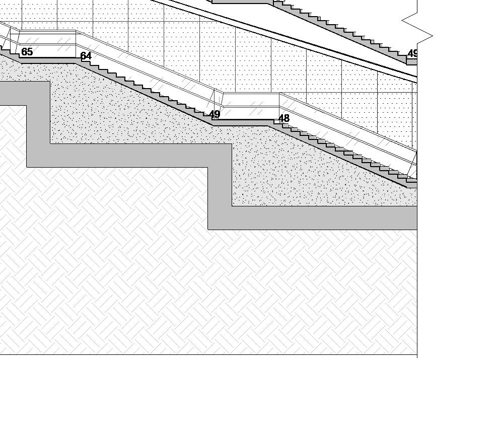
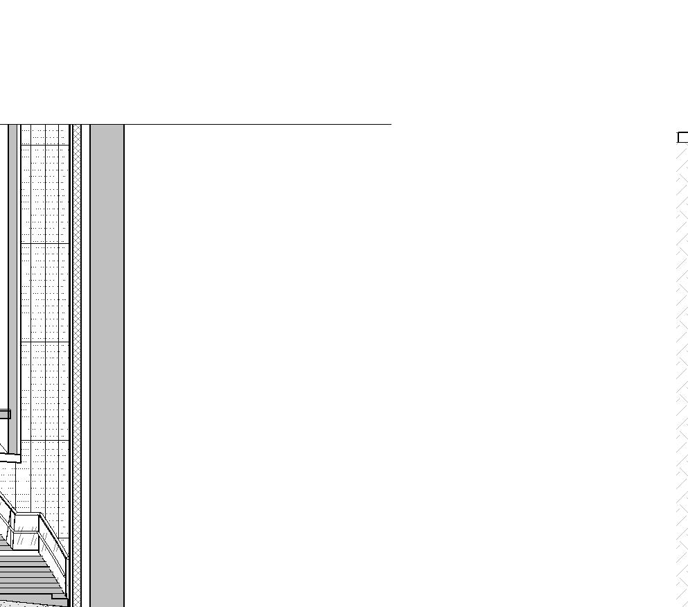
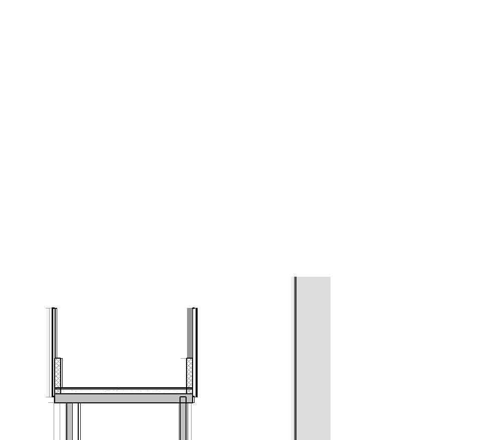
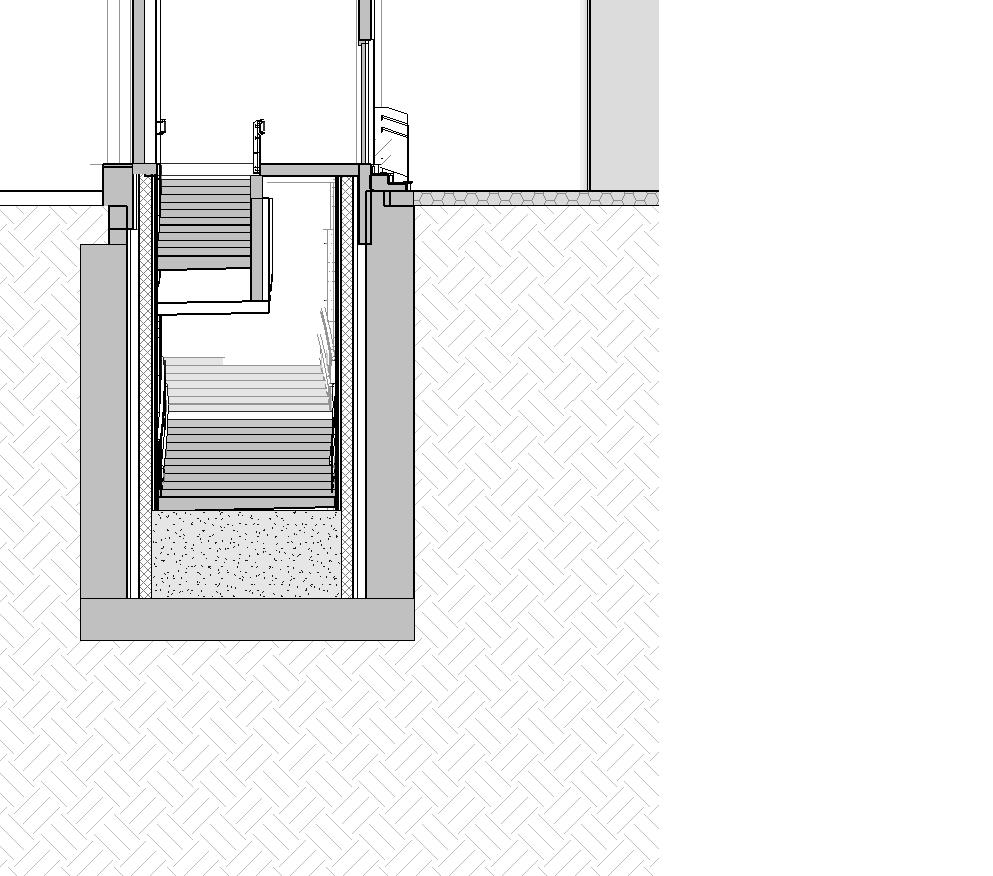

SL-3 EARTH FILL BELOW STAIRCASE -0.450 m BL -Top of Box Level 6.260 m GL -Ground Level 12.160 m 1FL -1st Floor Level 0.000 m MSL 7.610 m EL -Entrance Level-Exit 2 4000 MCW -1 EARTH FILL BELOW STAIRCASE LGP-2 - Toughened Lacquered Glass Panelling-Blue 4 16406 -0.450 m BL -Top of Box Level 6.260 m GL -Ground Level 12.160 m 1FL -1st Floor Level -7.050 m B1 -Concourse Floor Level 0.000 m MSL 7.610 m EL -Entrance Level-Exit 2 EARTH FILL BELOW STAIRCASE LGP-2 - Toughened Lacquered Glass Panelling-Blue AE-1 - Acrylic Emulsion Paint 3 16406 1.278 m FFL Acrylic Emulsion Paint BL -Top of Box Level S12-19 B1 -Concourse Floor Level S12-20 EMERGENCY STAIRCASE 12-B1-O-26 EXTERNAL STAIRCASE 12-B1-P-15 FSD 06 3595 CUTOUT IN D-WALL VOID LGP-2 - Toughened Lacquered Glass Panelling-Blue PB SHAFT-4 12-B1-M-15 EARTH FILL BELOW STAIRCASE AE-1 LGP-2 - Toughened Lacquered Glass Panelling-Blue Exit -2 Section BB 1 200 Exit -2 Section CC 3 1 : 200 Exit -2 Section FF 6 STAIRCASE MCW-3 - Security Glass Partition SL-3 - Vertical Louvers 12.160 m 1FL -1st Floor Level EL -Entrance Level-Exit 2 16405 16405 16405 -29.410 m B4 -Lower Platform Floor Level -13.150 m B2 -Plant Floor Level -0.450 m BL -Top of Box Level -30.510 m R1 -Lower Rail Level -32.850 m B4-Lower Undercroft Floor Level -20.710 m R2 -Upper Rail Level -19.610 m B3 -Upper Platform Floor Level -7.050 m B1 -Concourse Floor Level -23.050 m B3 -Upper Undercroft Floor Level OTE SHAFT CUTOUT IN FLOOR UPE CUTOUT 6600 6100 6460 1100 2340 6360 0.000 m MSL SERVICE CORRIDOR 12-B2-C-02 TVF PANEL ROOM 12-B2-M-07 ANTI ROOM 12-B3U-O-01 VL(EV) SHAFT 12-B3U-M-09 ANTI ROOM 12-B3-O-06 ANTI ROOM 12-B4-O-05 ANTI ROOM 12-B2-O-03 UPE SHAFT 12-B4U-M-03 UPE SHAFT 12-B3U-M-08 CONNECTING CORRIDOR 12-B1-P-25 CUTOUT IN FLOOR ℄ OF TRACK PLATFORM EDGE 1600 4800 3500 32400 51601200 0 3040200 200 5160110020048001100 200 52001400 1 16202 2 16202 8600 PMC-2 BCS-1 3000 5200 1600 1700 300 400 1700 5100 OTE SHAFT FHC 1500 UNPAID CONCOURSE 12-B1-P-20 900 900 1200 1800 3000 3200 BCS-1 BCS-1 FSD 02 3200 ADP-1 ADP-1 5600 5600 5100 300 4001700 GRC-1 AE-1 AE-1 800 800 400 400 1000 1000 500 KINEMATIC ENVELOPE KINEMATIC ENVELOPE 1700 2800 ADP-1 1 16302 2 16302 1 16302 2 16302 3 16202 4 16202 2800 UPE CUTOUT 2400 SPACE FOR CABLE TRAYS SPACE FOR CABLE TRAYS VL(EV) SHAFT 1 16202 2 16202 1 08201 PROJECT TITLE CLIENT DHAKA MASS RAPID TRANSIT DEVELOPMENT PROJECT (LINE 5): NORTHERN ROUTE JICA LOAN NO. BD -P101 Dhaka Mass Transit Company Limited (DMTCL) Dhaka, Bangladesh MFCA (Metro Five Consultants Association) CONSULTANT Oriental Consultants Global Co., Ltd Delhi Metro Rail Corporation Ltd Katahira and Engineers International Development Design Consultants Ltd CONTRACT TITLE DESCRIPTION DATE PREPARED BY APPROVED BY CHECKED BY AF PMJ KK DESIGN PARTNERSHIP SHALL HAVE NO RESPONSIBILITY FOR ANY USE MADE OF THIS DOCUMENT OTHER THAN FOR THAT WHICH IT WAS PREPARED AND ISSUED. DIMENSIONS SHOULD BE CHECKED ON SITE. DRAWING ERRORS OR DIVERGENCIES SHOULD BE BROUGHT TO THE ATTENTION OF BUILDING PARTNERSHIP AT THE ADDRESS SHOWN BELOW. DRAWINGS SHALL BE READ IN CONJUNCTION WITH THE FOLLOWING BEFORE WORK COMMENCES: THE HEALTH AND SAFETY DESIGN ISSUES REGISTER THE BDP RISK SERIES OF DRAWINGS THE PROJECT HEALTH AND SAFETY RISK REGISTER SCALE FROM THIS DRAWING STRUCTURE IS BASED ON INFORMATION RECEIVED FROM CLIENT. CHANGES ARE SUBJECT TO REVISION NOTE: PLATFORM EDGE AS PER PLATFORM EDGE DRAWING -0.450 m -3 TREAD WIDTH 112 @130.9 mm ST-02 (B1 TO GFL) 300 mm 3000 mm RISER TREAD WIDTH 300 mm 65 @129.4 mm FST-01 (B1 TO GFL) 1800 mm BELOW STAIRCASE -2 LGP-2 LGP-2 Sections
12-B1-P-10
12-B1-M-08 VL(EV) SHAFT-6
12-B1-M-32
12-B1-P-21
12-B1-M-04
16 1 32 17 48 33 64 49 80 65 96 81 112 97 15 1 41 31 23 16 39 31 S12-19 S12-A S12-E S12-B S12-18 S12-C S12-17 S12-D S12-E2-01 S12-E2-02
S12-E2-06 6 09303 S12-E2-B FHC 4400 1200 1200 1200 3860 1800 1880 750 VOID 4400 4360 10000 PUBLIC
S12-E2-03 S12-E2-04 S12-E2-05
TOILET (FEMALE)
EXTERNAL STAIRCASE 12-B1-P-15
CLEANER ROOM (PUBLIC)
INTERNAL
ELV-2 12-B1-P-18 EMERGENCY STAIRCASE 12-B1-O-26 PB SHAFT-3
VL(EV) SHAFT-7
EPS-4
PB
UP TO GFL DN 1500 5500 3600 5690 S12-E2-A 1 09303 2 09303 3 09303 4 09303 5 09303 + -7.250 m RISER TREAD WIDTH 112 @130.9 mm ST-02 (B1 TO GFL) 300 mm 3000 mm BACK FILLING ANTI ROOM 12-B1-O-21 S12 BUILDING DESIGN PARTNERSHIP SHALL HAVE NO RESPONSIBILITY FOR ANY USE MADE OF THIS DOCUMENT OTHER THAN FOR THAT WHICH IT WAS PREPARED AND ISSUED. ALL DIMENSIONS SHOULD BE CHECKED ON SITE. NOTES B1 -Concourse Floor Level -Exit 2 Plan Concourse Entry
12-B1-E-11
SHAFT-4 12-B1-M-15 TOILET CORRIDOR 12-B1-P-17
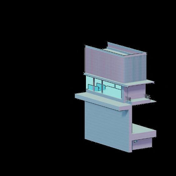
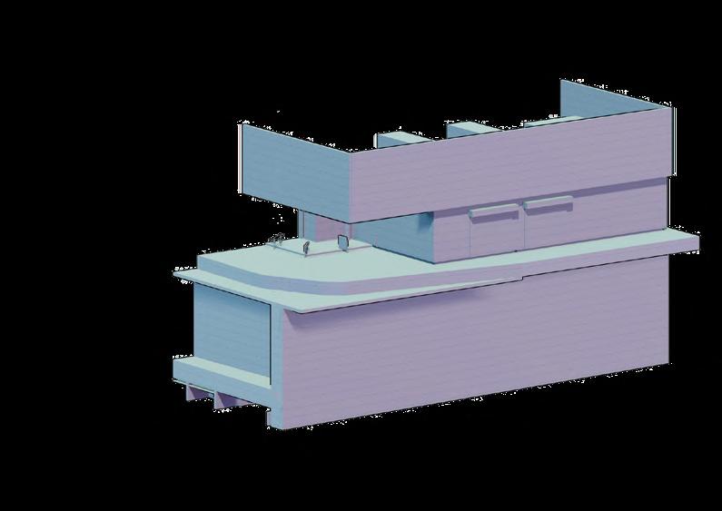
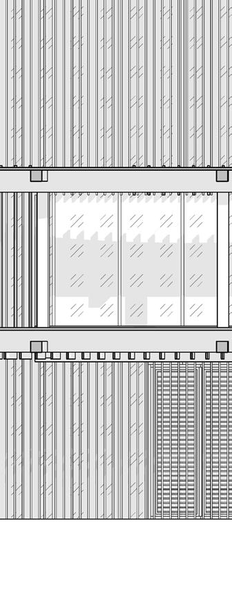
Each station had similar design palette for the substructure, (except for Gulshan and Banani), while all stations had a difference language for their superstructure . Details were crafted for each of these stations very carefully as visual appeal, material and resource availability in Bangladesh, Flood Water drainage and ventilation and circulatory elements played a major role in the design.
This is an overview of the design vocabulary of some of the station cores.
Three major material finishes are evident in all stations, namely, Lacquered Glass reinforced Concrete and Brick Cladding; in addition to exposed concrete and Curtain walls.
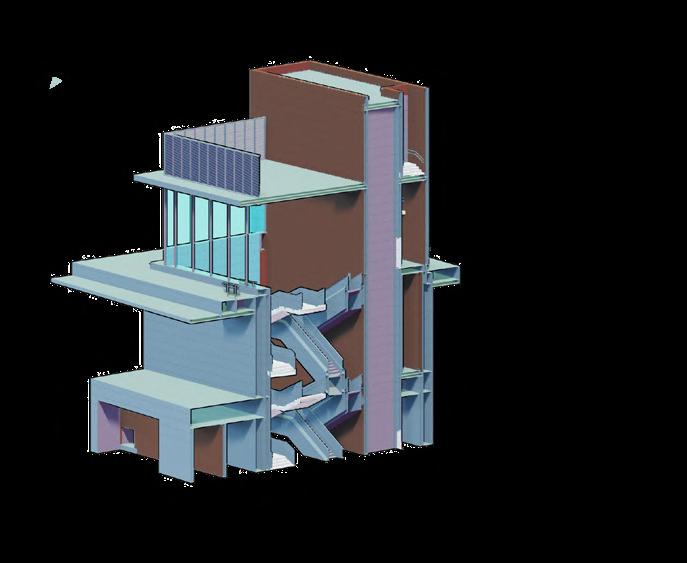
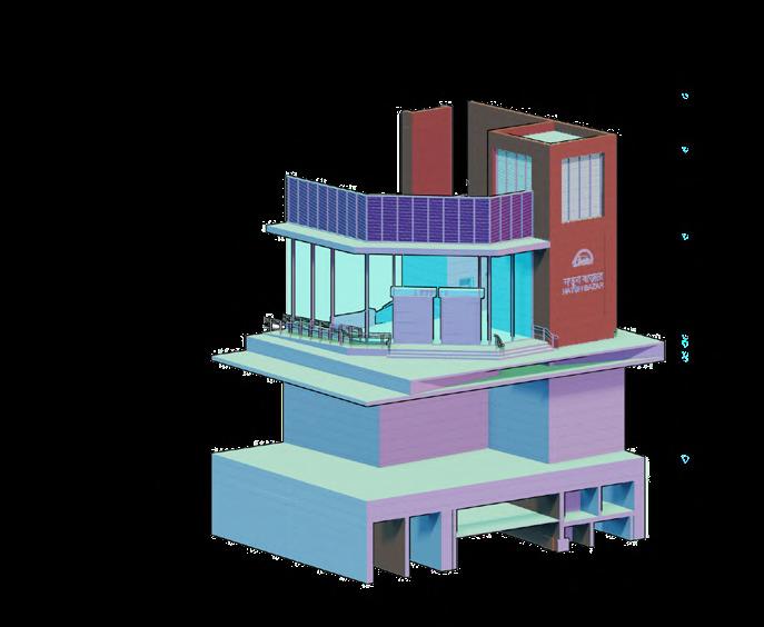
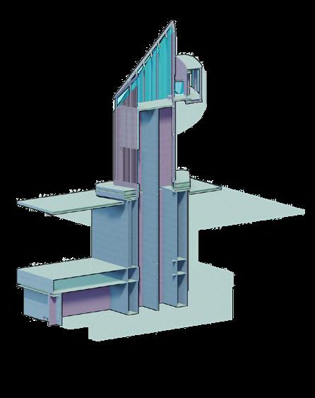
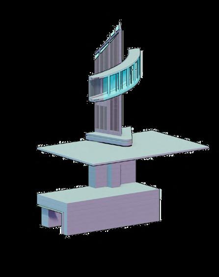
Ground Structure Typology Assemblies
Mirpur -14 Exit 3
Mirpur -14 Exit 2
Gulshan 2 Vent Core
Gulshan 2 Exit Core 1
Notun Bazar Exit Core
Banani Exit Core
Gulshan 2 Exit Core 2

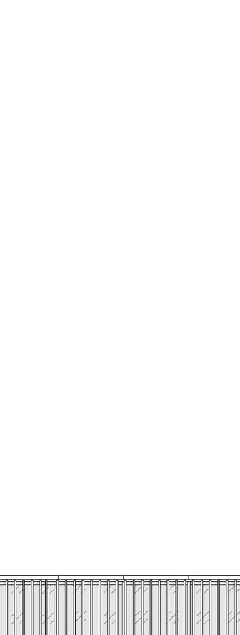
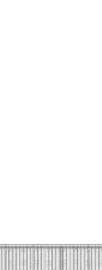


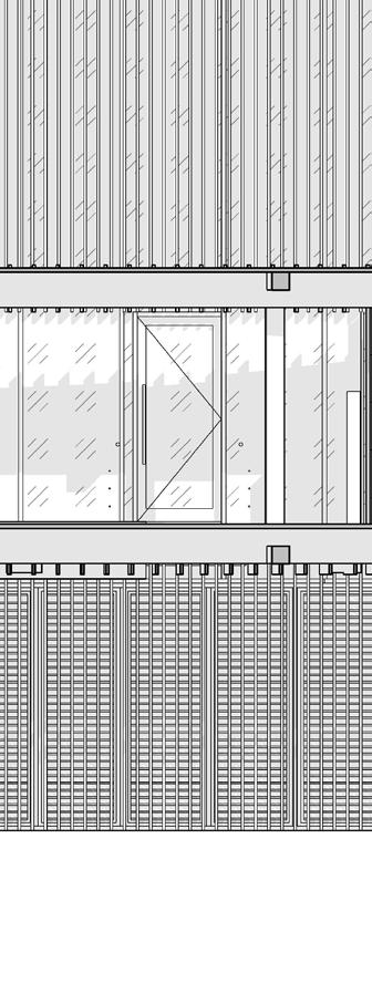
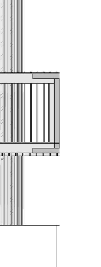
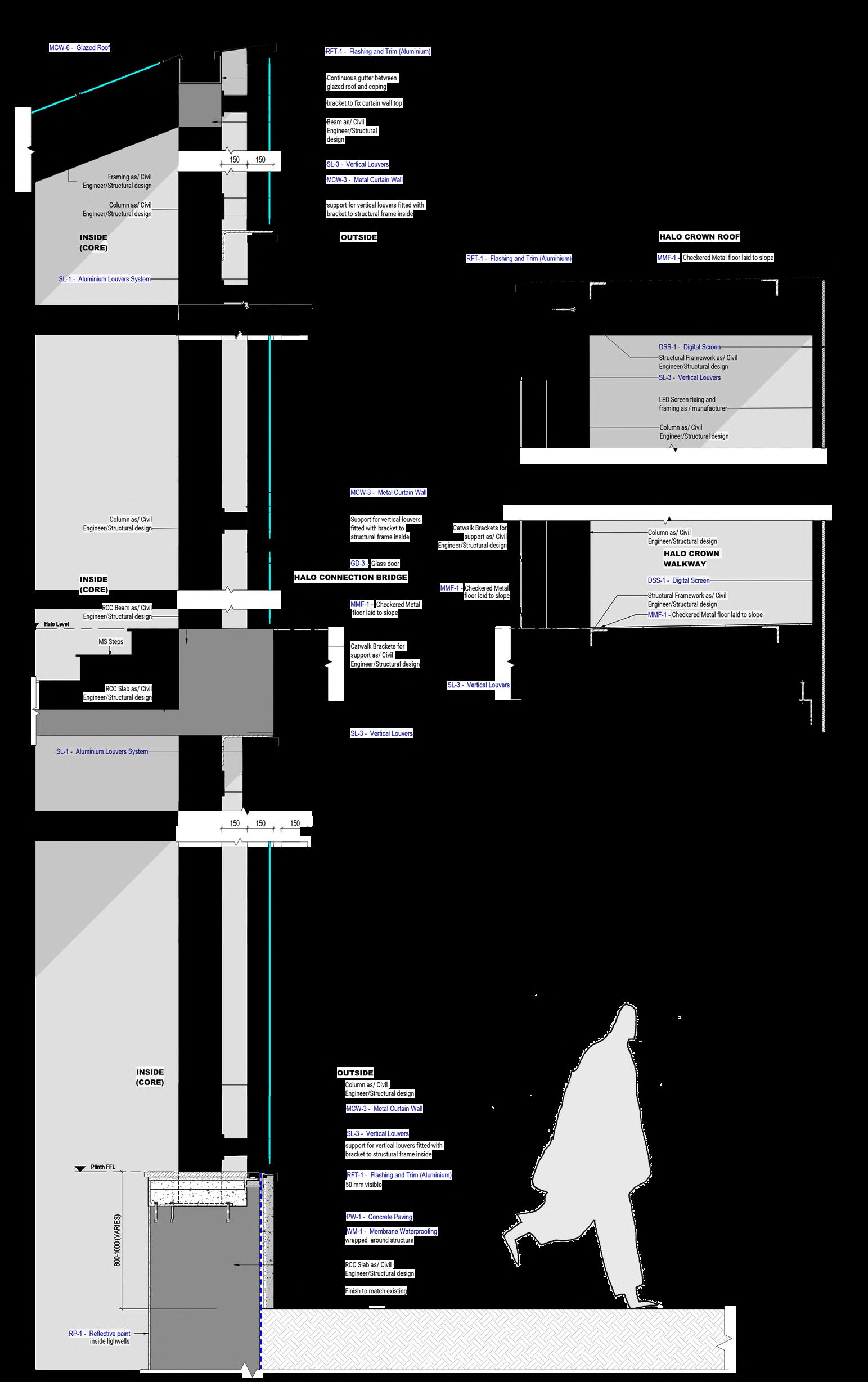
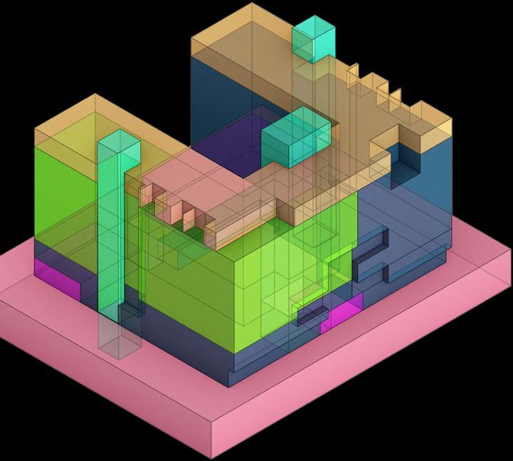
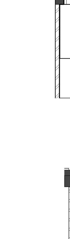
Elevation 3D Section Core and Halo
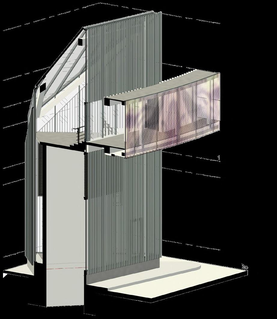
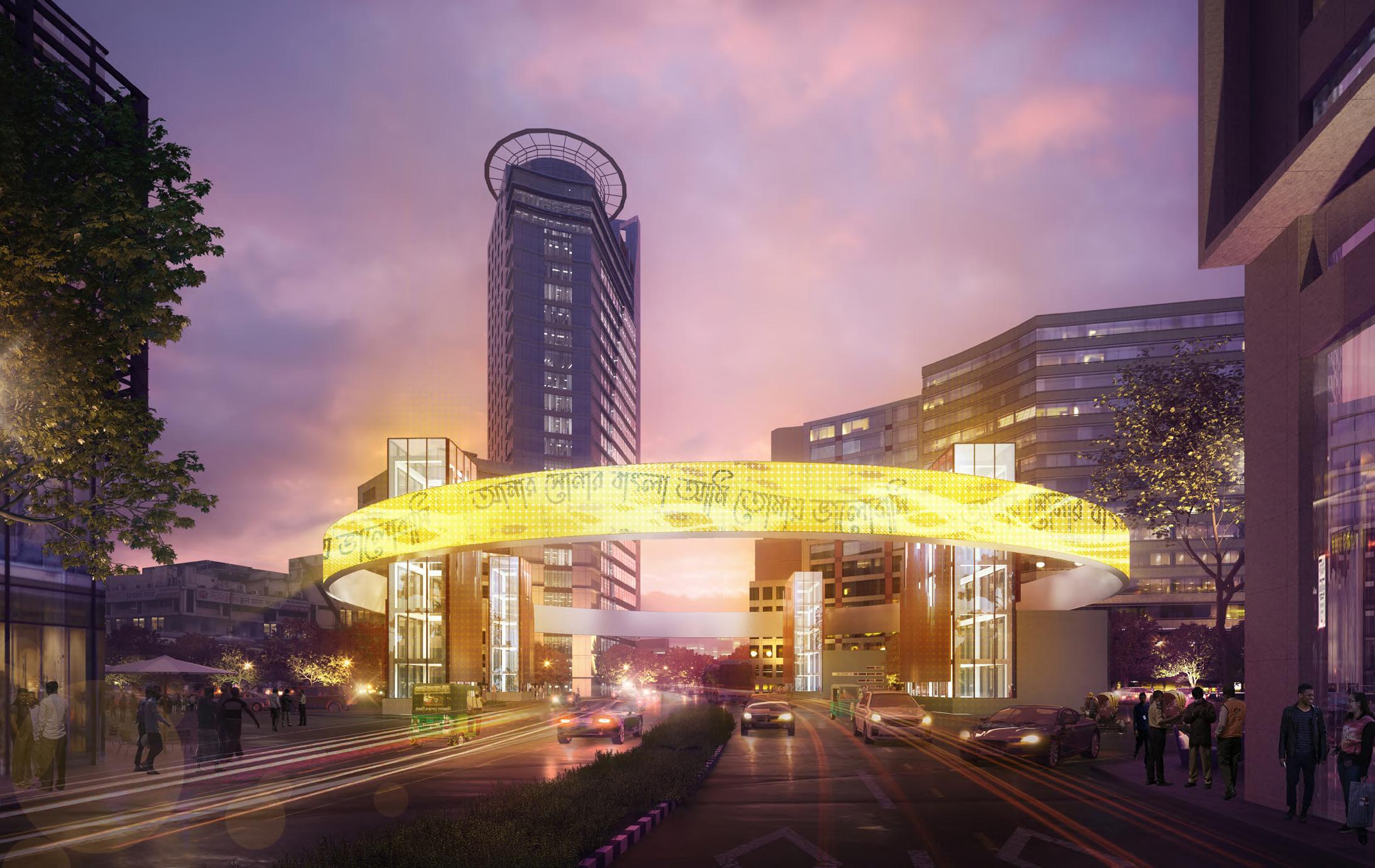
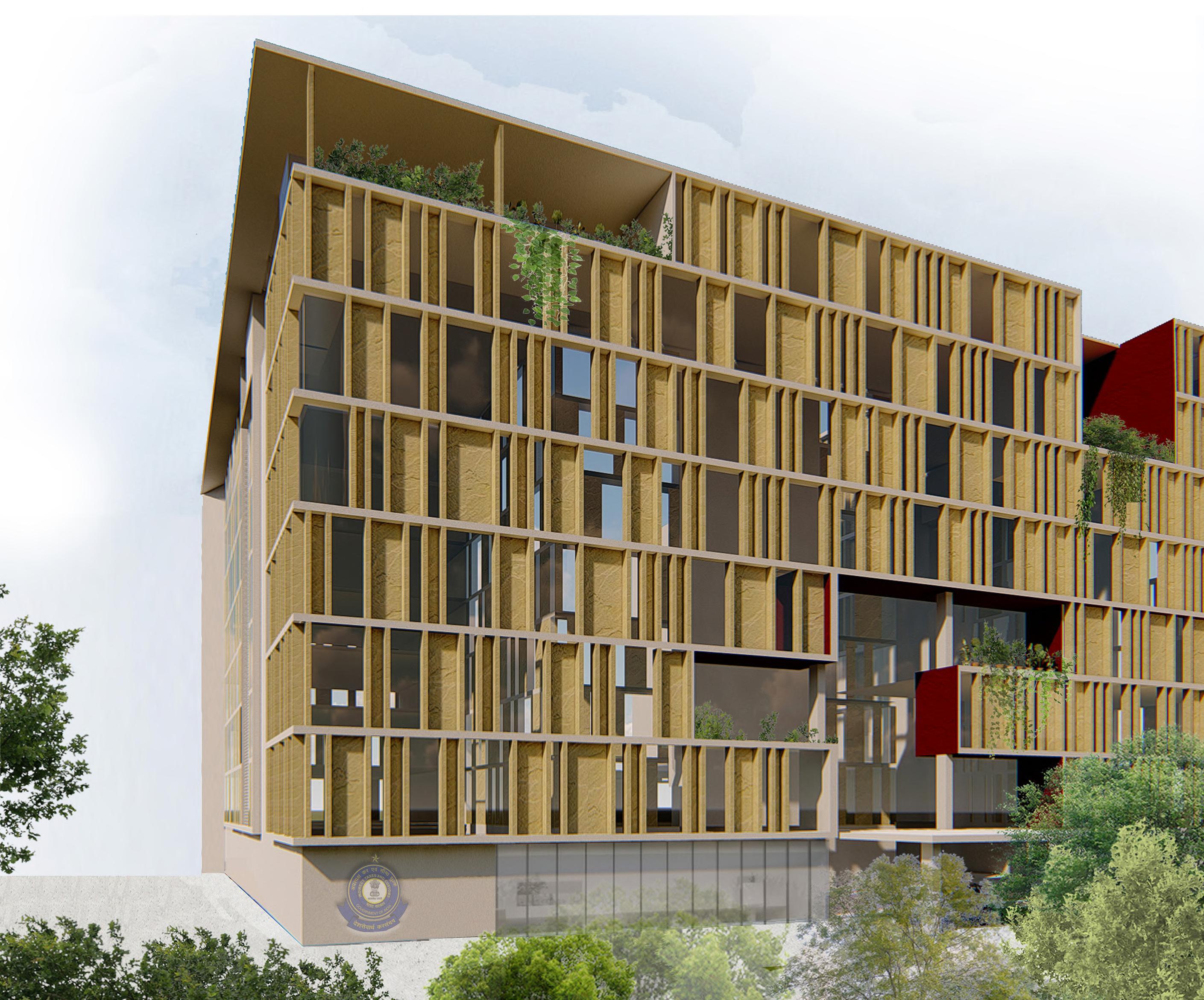
-Cores -Cores 2400 HALO CONNECTION BRIDGE SL-3 - Vertical Louvers MCW-3 - Metal Curtain Wall MCW-3 - Metal Curtain Wall SL-1 - Aluminium Louvers System INTEGRATED WITH CURTAIN WALL 1500 2900 GULSHAN CORE EXTERIOR VIEW
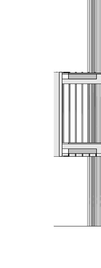
As there was particular emphasis on facade systems and cladding, there were 2 separate set of drawings; a STANDARD set and a SPECIFIC set for each station.
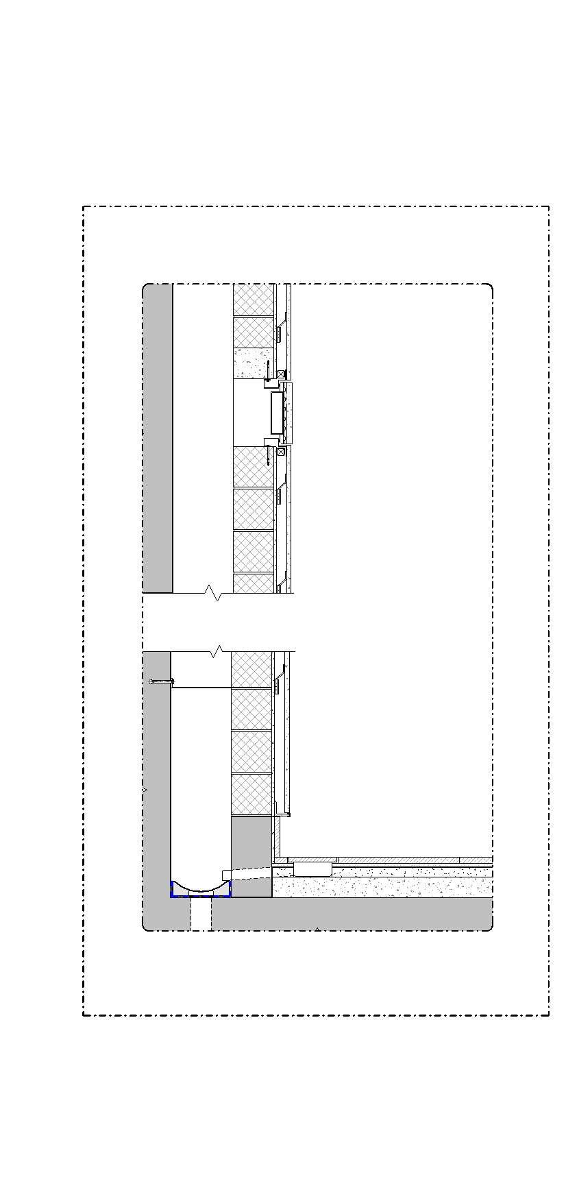
Gulshan, for instance has Glass Cores to let maximum light in, with a Screen Around the Cores. Intricate Joining Details were designed at intersection of various elements like the catwalk, th junction of louvers, glazing ,the glass roof and the screen.
The use of Collaboration on BIM played a key role in coordinating with different design teams and managing information like keynotes, tags , quantities ,etc. among various disciplines.
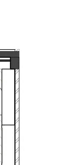
FS-1- Granite - Type 1 PAS-1-Screed RCC Slab as/ Civil Engineer/Structural design Cavity Wall Tie Nahni Trap SDC-1-Granite Slotted Drain Cover 300 RCC curb upstand as/ others PAS-3- Structural Screed Drain in screed laid to slope as/ others GRC-1- Glass Fibre Reinforced Concrete Panelling WS-3 - Granite Skirting 50 LC-1 - AAC Blockwork Wall RCC lintel as/ Civil Engineer/Structural design PCP-2 - Cement Plaster 300 GRC-1 - Glass Fibre Reinforced Concrete Panelling LC-1 - AAC Blockwork Wall D-Wall as/ Civil Engineer/Structural design ADW-3 - GRC Panel Access Hatch size 600mm min. opening CONSULTANT MFCA (Metro Five Consultants Association) Nippon Koei Co., Ltd Oriental Consultants Global Co., Ltd Systra S.A Delhi Metro Rail Corporation Ltd Nippon Koei India Pvt, Ltd Katahira and Engineers International Development Design Consultants Ltd, REV. DATE DESCRIPTION C12C -GRC clad Cavity Wall junction 1 20 P0121.12.2022DETAIL DESIGN- FINAL SUBMISSION P0217.03.2023DETAIL DESIGN - ISSUE FOR Detail Core and Halo
Detail
Standard
Concourse Wall
PATTERN
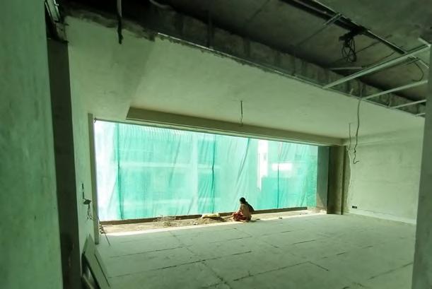
Goods and Service Tax HQ Building, Ghaziabad 2020-2022
Professional Project (Under Construction) Softwares Used : Revit Grasshopper
Worked with Studio Next Project Type : Commercial
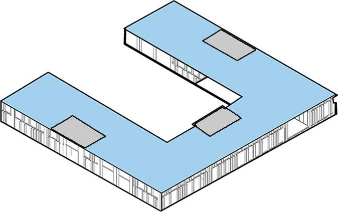
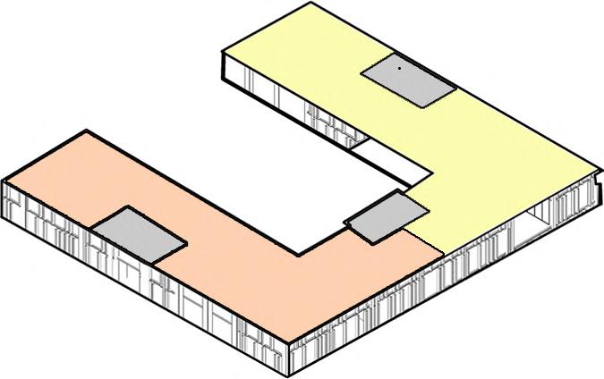
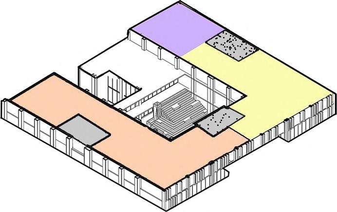
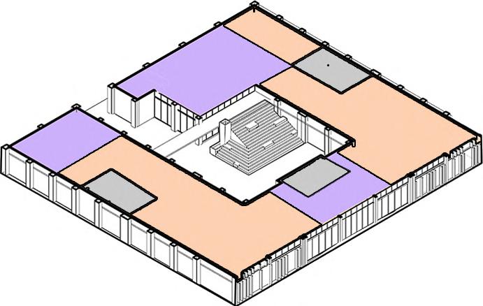
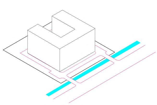
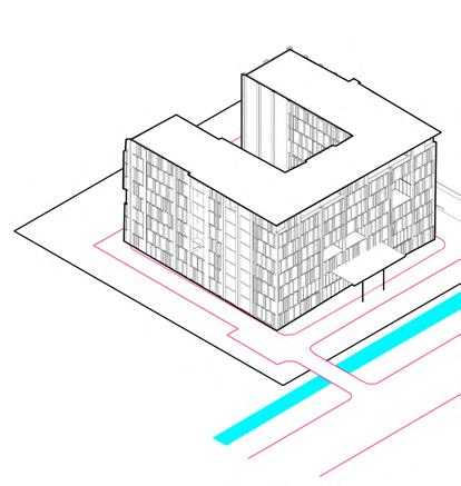
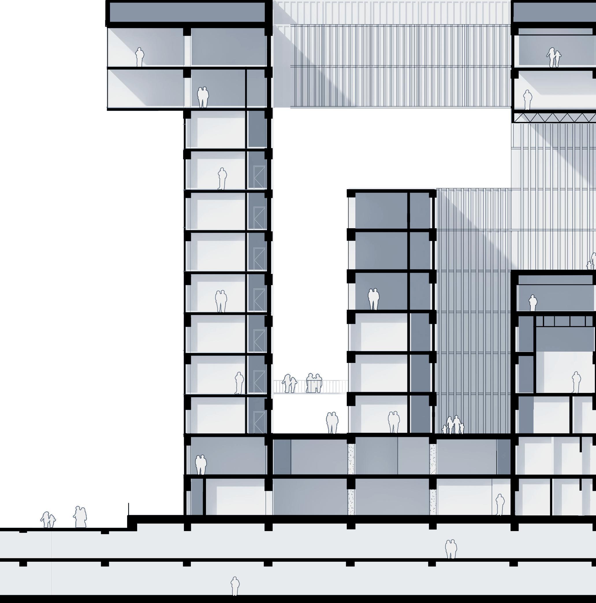
The proposed design is a contemporary building reflecting the modern ideology of GST. The overall planning focuses on creating “people centric spaces”. The lower floors comprise of public spaces including a Cafeteria, Gymnasium and a Multipurpose Hall around a central courtyard. The courtyard provides ample natural light into the office spaces at all levels. Terraces as “sky gardens” on upper levels provided the much need relief and connection to the outdoors contributing to the healthy work environment for the staff. Modular office layout is planned for seamless working between various divisions and groups of GST.
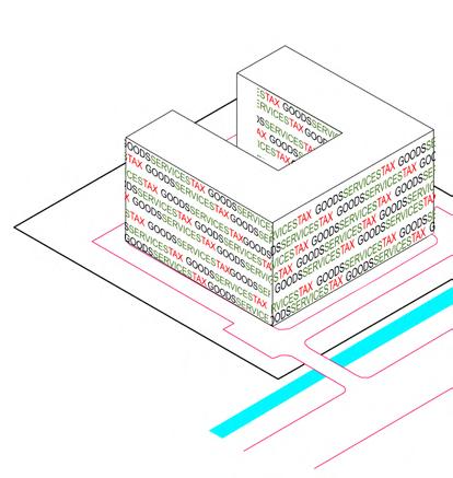
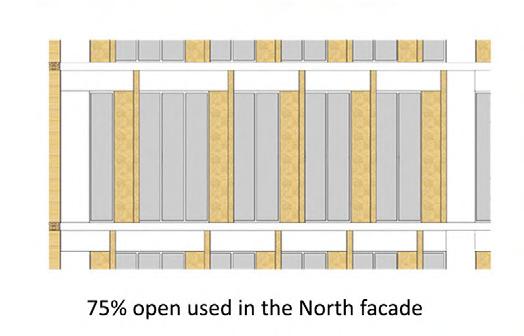
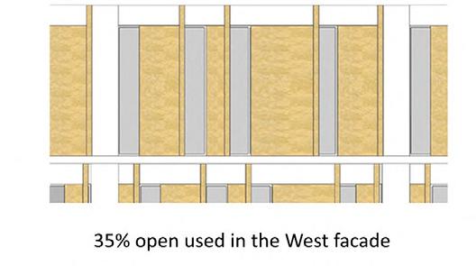
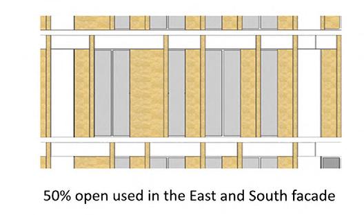
A sculptural facade system based on the “Bar Code” language of “Goods and Services Tax” wraps the building in stone cladding interspersed with fenestrations in such a manner that heat gain is minimized and good daylight is maximized.

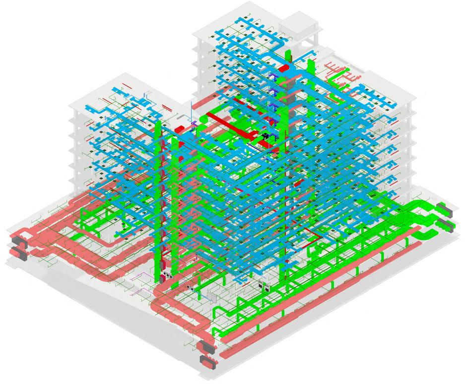
The Coordination of this project was particularly challenging,given the number of complex services we had to manage. The optimization of data was carried out through a consistent use of schedules,coordinated models, and computational design methods. Particular emphasis was given to information handling systems, to create clean and clash free models. By the Implementation of BIM Model, it became an uncomplicated process to calculate the energy loads of the building to optimise the entire system.
HVAC Services
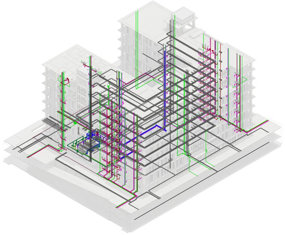
Plumbing Services
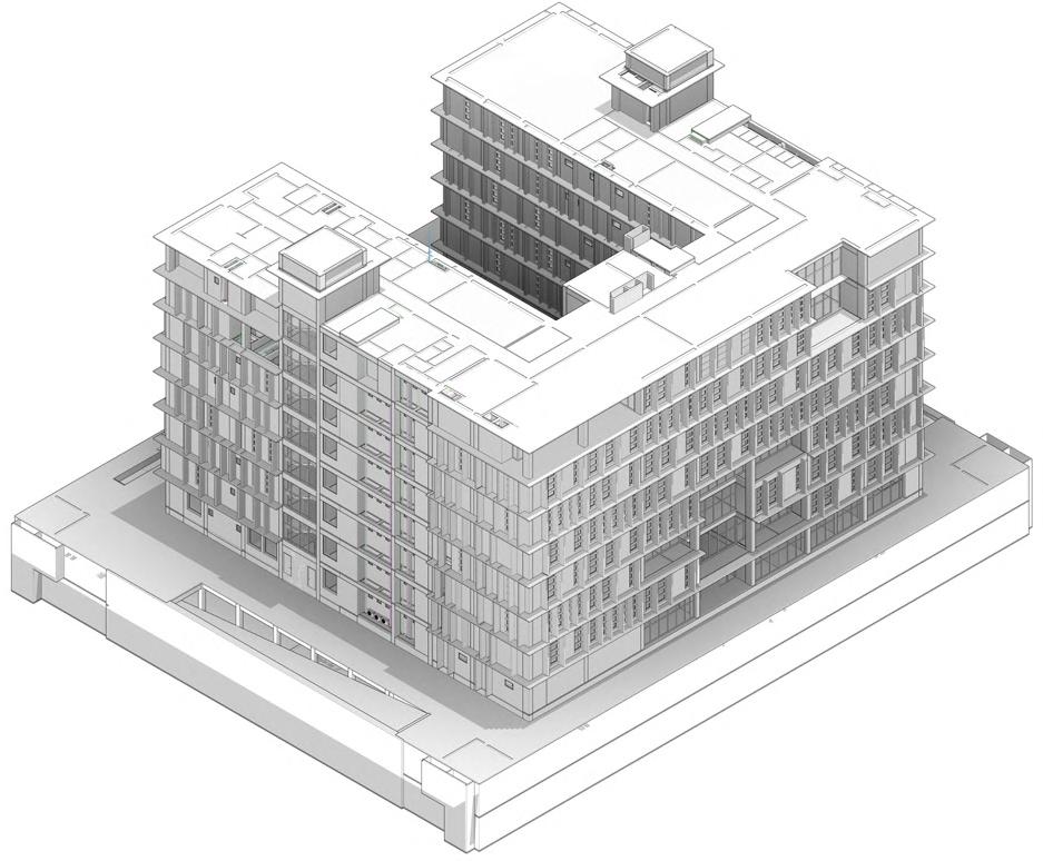
Co-ordinated BIM Model Exploded Function
Activity Areas Circulation Cores Parking Guest Rooms Office Type 2 Office Type 1 Parking
Lobby Cafe Gymnasium
Chief
Office Space Guest House Guest House Cores Parking Office Type
Office Type 1 Basement L1-L2 Ground Floor First Floor 2nd-6th Floor 7th Floor
Entrance
Multipurpose Hall
Commissioner Office
2
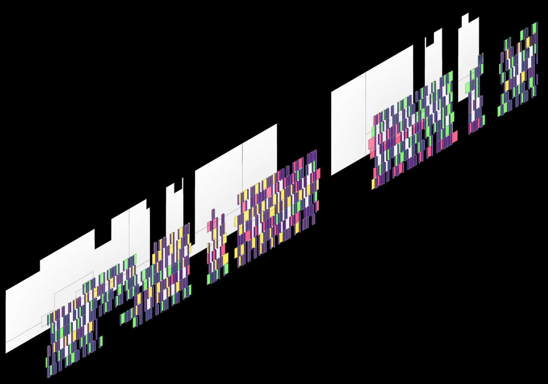
The conceptual planning of the building was already undertaken bey the government agency. But it was quite clear while designing that the building must have some unique feature. Given the orientation of the building it was necessary to think of a system to hold back high solar radiation while maintaining natural ventilation of the spaces. A strategy of fins was derived based on bar code system of “Goods and Service Tax”. The conceptual scheme derived in the bar code design was optimized though various analysis.
Fin System Optimization was enabled by use of computational design systems through form finding based on heat gains.
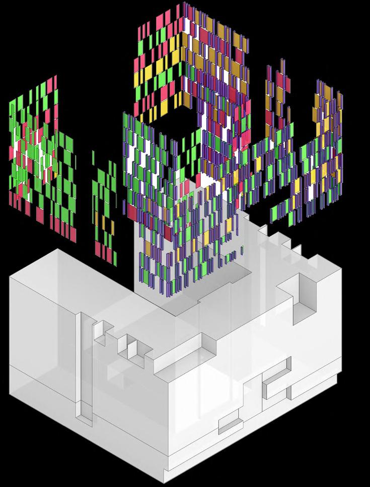
FORM EVOLUTION
 Unrolled Facade System
GST
Fin
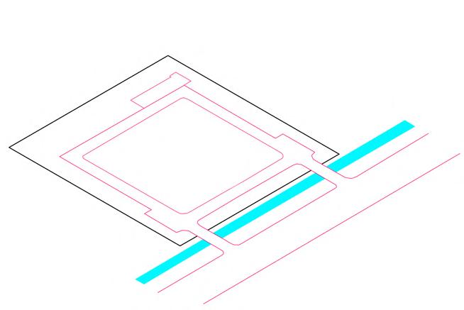
Existing Site Base Mass
Wrap
Translation Base Form
Facade Screen
FIN TRANSLATION
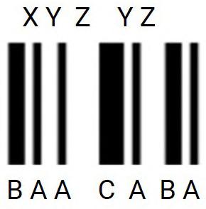
ABC, XYZ refer to various ratios for solid and glass opimised base on daylight analysis. These Letter are used for ease of construction.
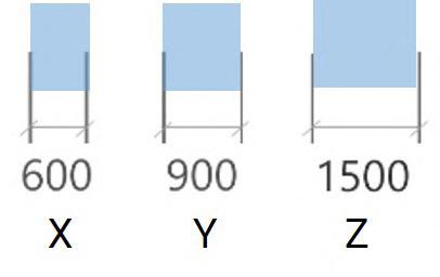
Glazed Panels
The bar code translation of GST is repeated in a pattern derived from below analysis. Various size of bands, are referenced as solid A,B,C Panels, while voids are considered as glazed X,Y,Z panels. The result is a facade that responds to sun in a very dynamic way but has a strong sensibility behind it.

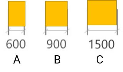
Solid Panels
Fins
“Goods” panels
“Service” panels
“Tax” panels
The building is striving towards achieving a Five-star GRIHA rated building by incorporating various greens strategies including a Double walled system, fenestrations and louvers, conscious design to meet Energy Performance index of materials etc. It is the pilot project to be registered under GRIHA V19.

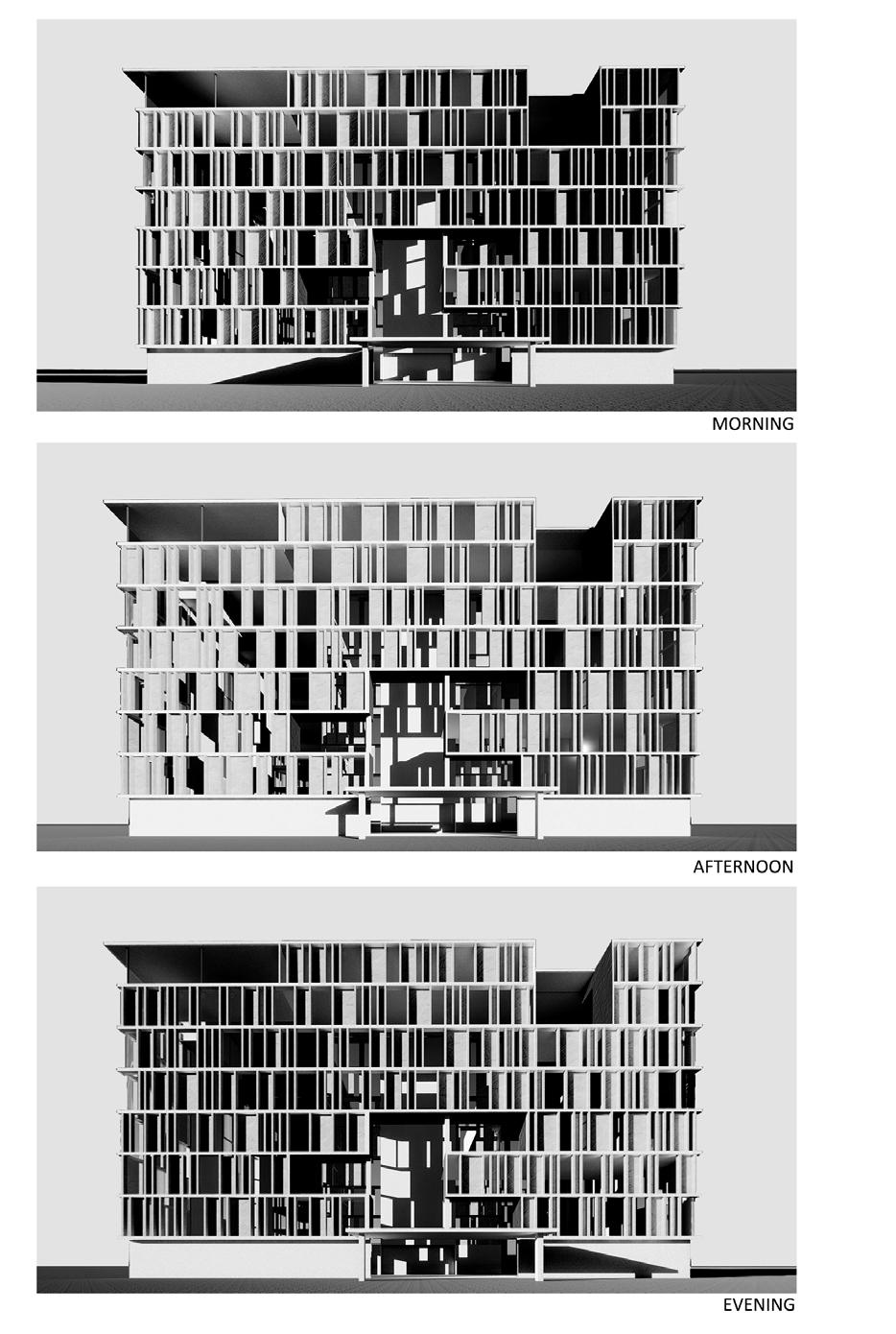
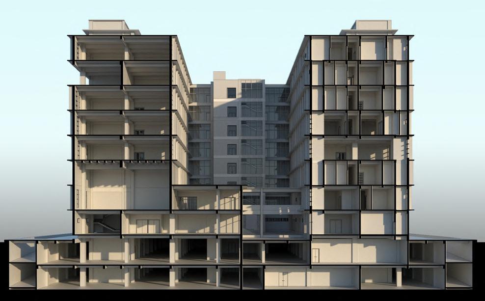
Section through court & cafe
Daylight Hours Analysis
CLAY/MORTAR
Site Area : 4000 sqm.
Professional Project
Softwares Used : Revit Grasshopper
Worked with Studio Next Project Type : Institutional
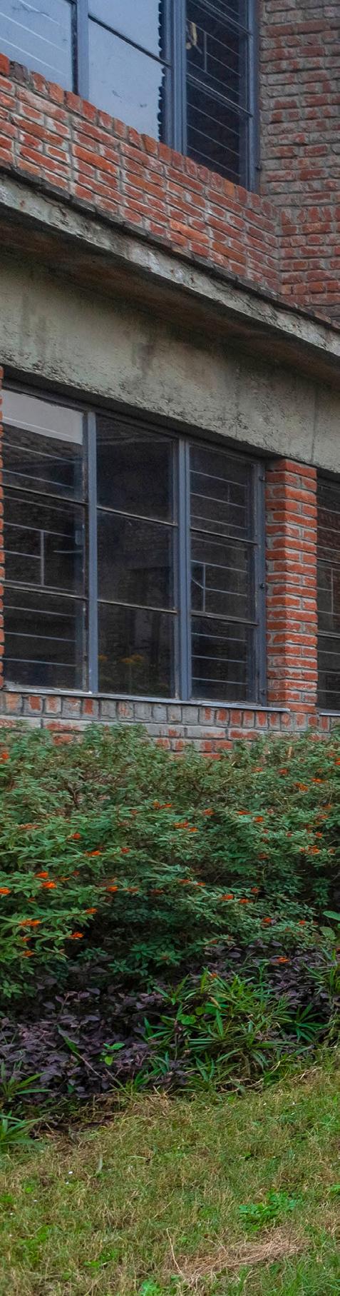
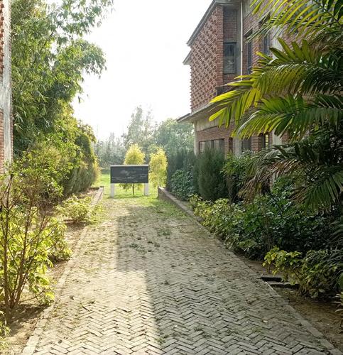
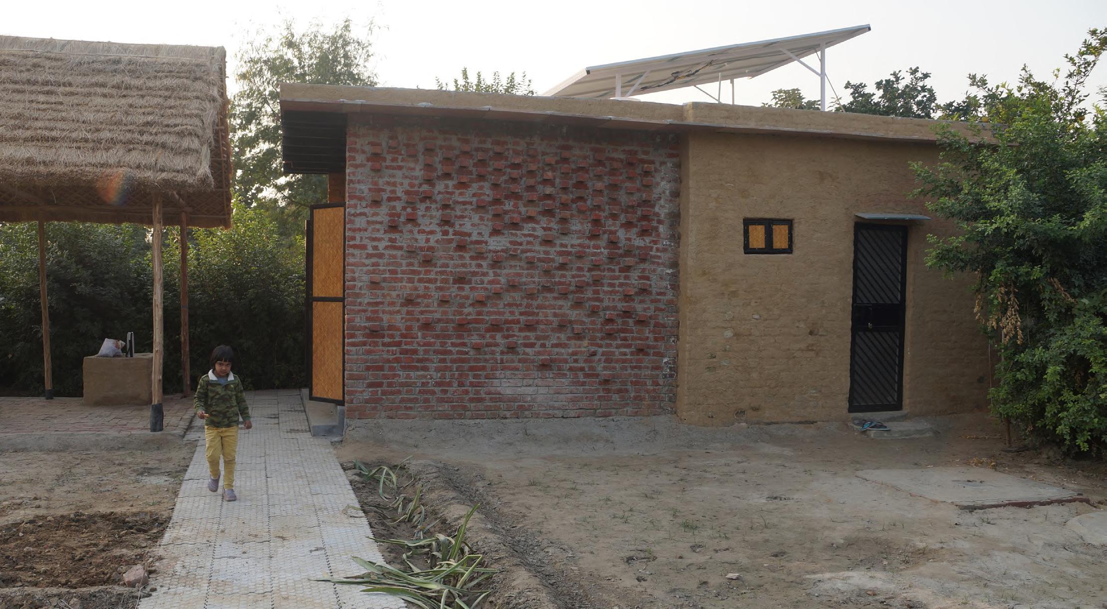
The G+1 junior school building is primarily designed to trigger the senses. The built environment sensitises the students to color, light, texture, smell, sound. The students are always connected and have a vision of the outdoor spaces as they move all through their building enabling them to experience various sounds, smell, light. Varied textures and colors is experienced by using natural materials such as exposed brick & concrete on the façade and mosaic & Kota stone flooring. There is play of light through openings and brick jaalis at various locations, which change through the day as the sun moves.

I didn’t know bricks could be used like that. Can you design my home?

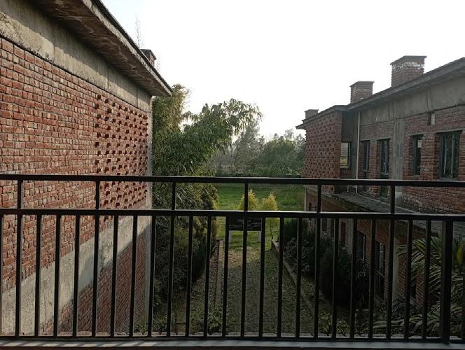
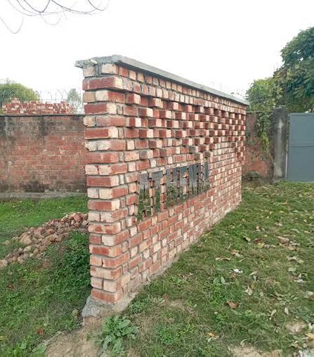
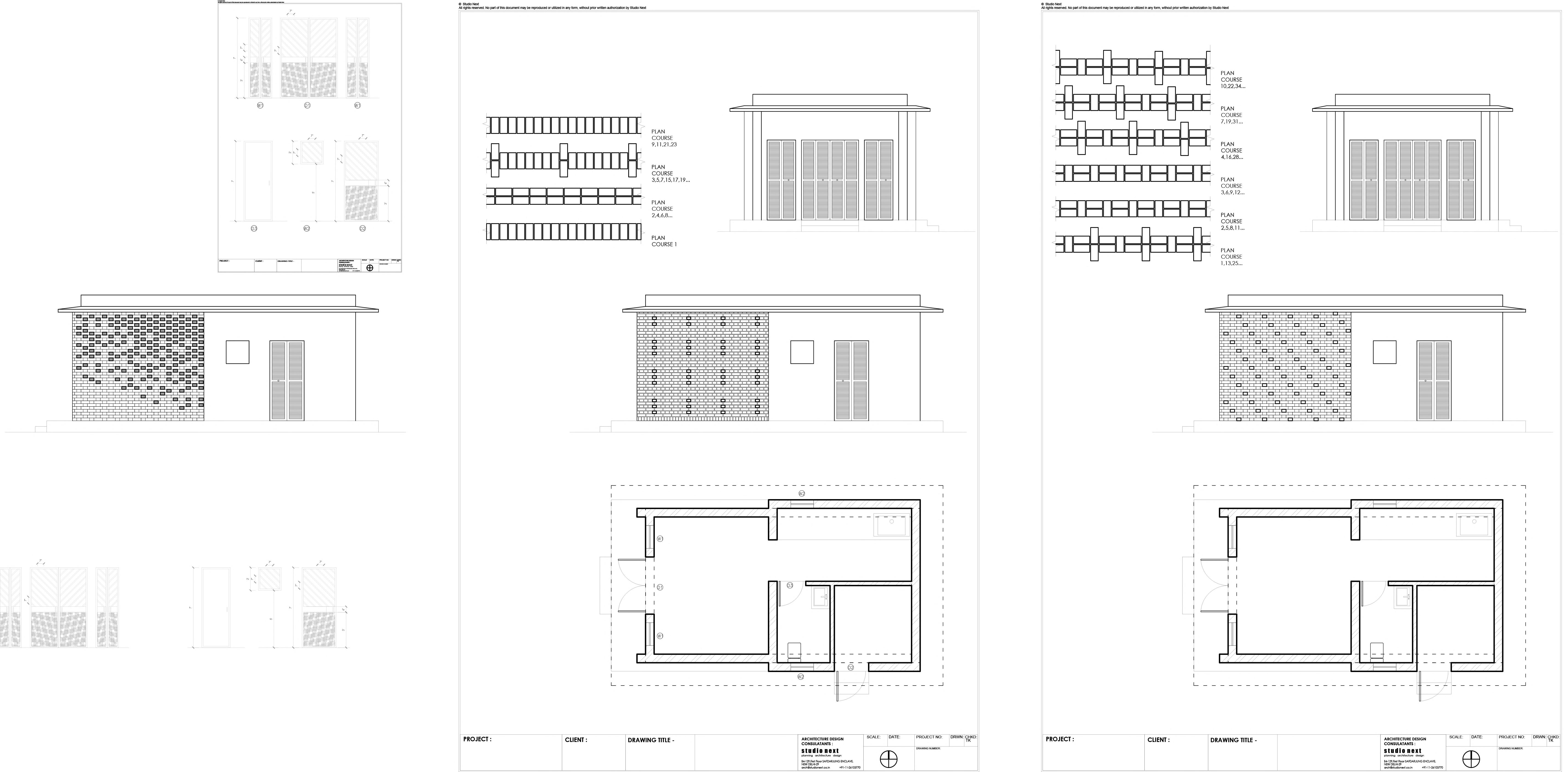
Sustainable School Design for Athenia Society, Saharanpur 2021 The site was previously a brick-baking kiln, which now has been abandoned. The project was a experiment of various patterns in brick.
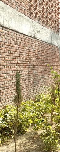
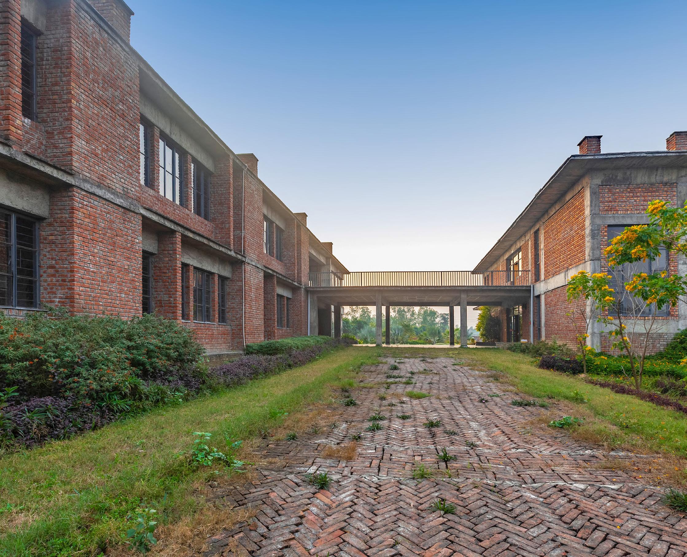
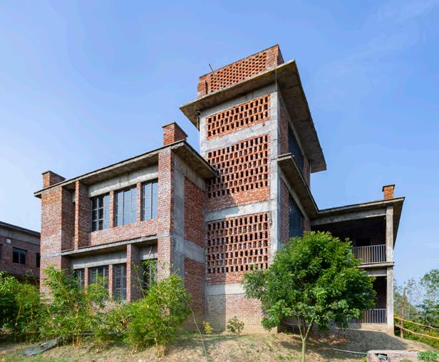
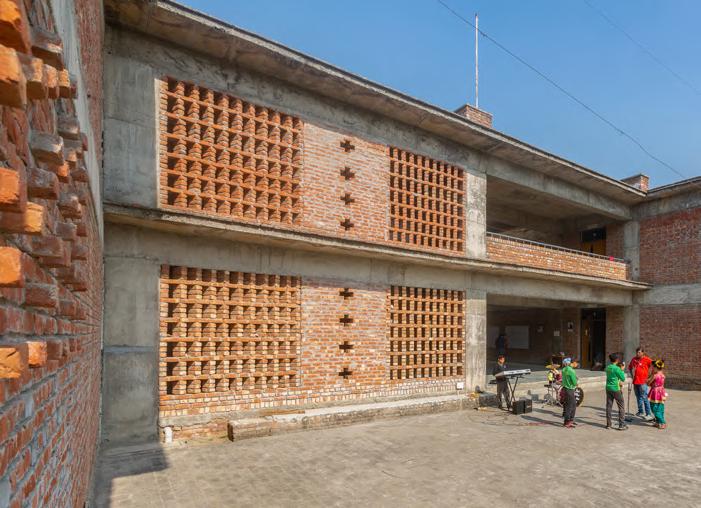
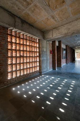
Till the end of the project the entire building team were masters of brickwork and invented patterns and bonds on their own.
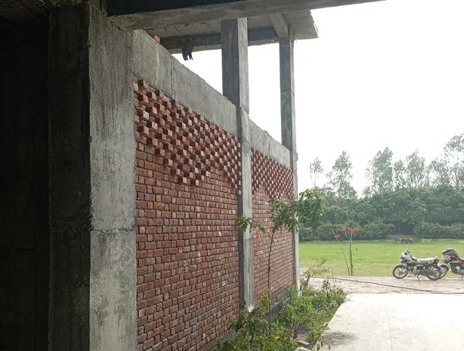
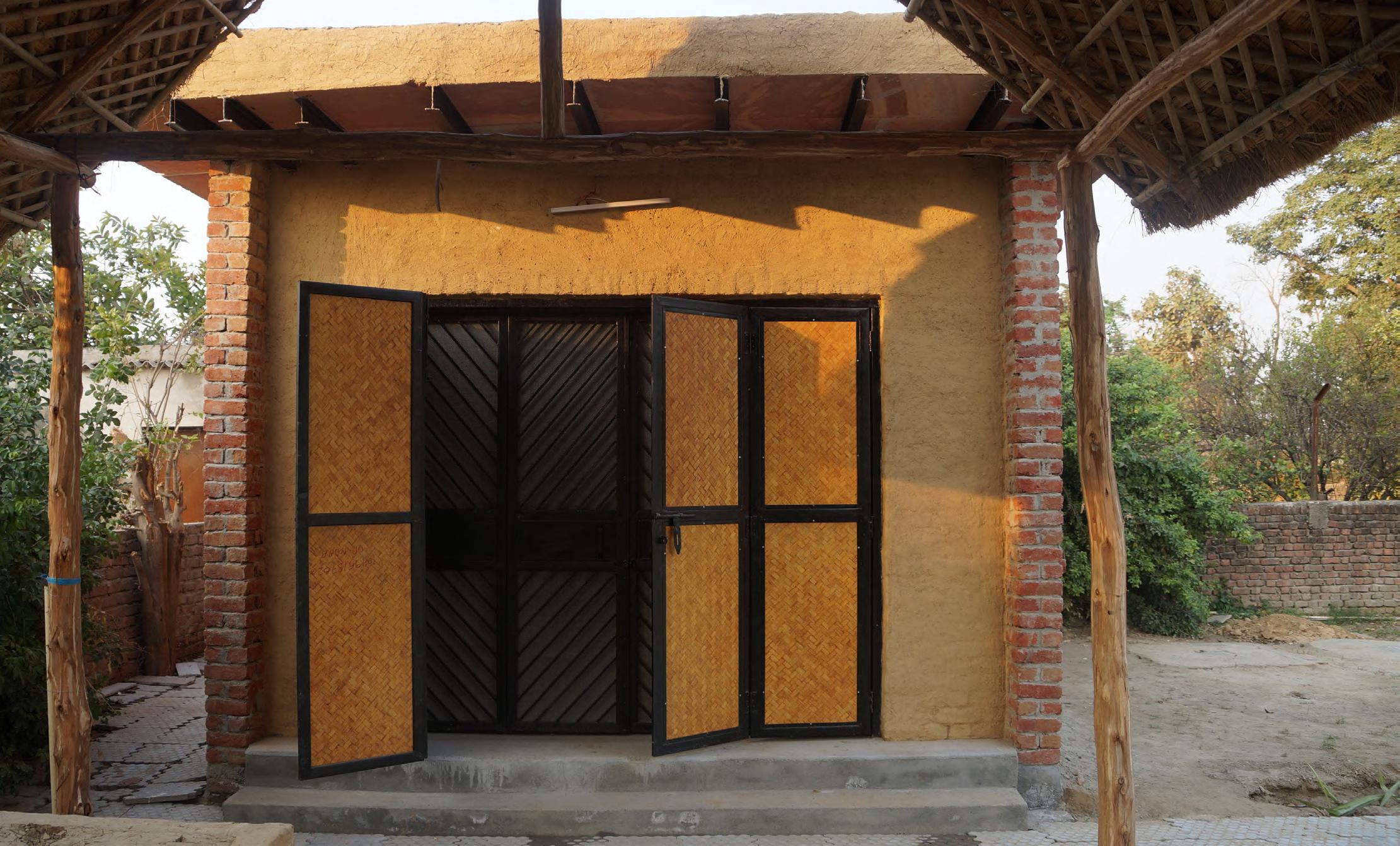
Mason’s Home, Noida 2021
Site Area : 40 sqm.
Professional Project Softwares Used : Revit Grasshopper
Project Type : Residential
A mason was so impressed by the pattern of extruded bricks derived from Grasshopper that he asked me to do the same for his home !! Ironically, in a nation that focuses on brickwork construction, buildings are still made with use on english bond only.
Funnily, I also designed a bamboo shed for him.
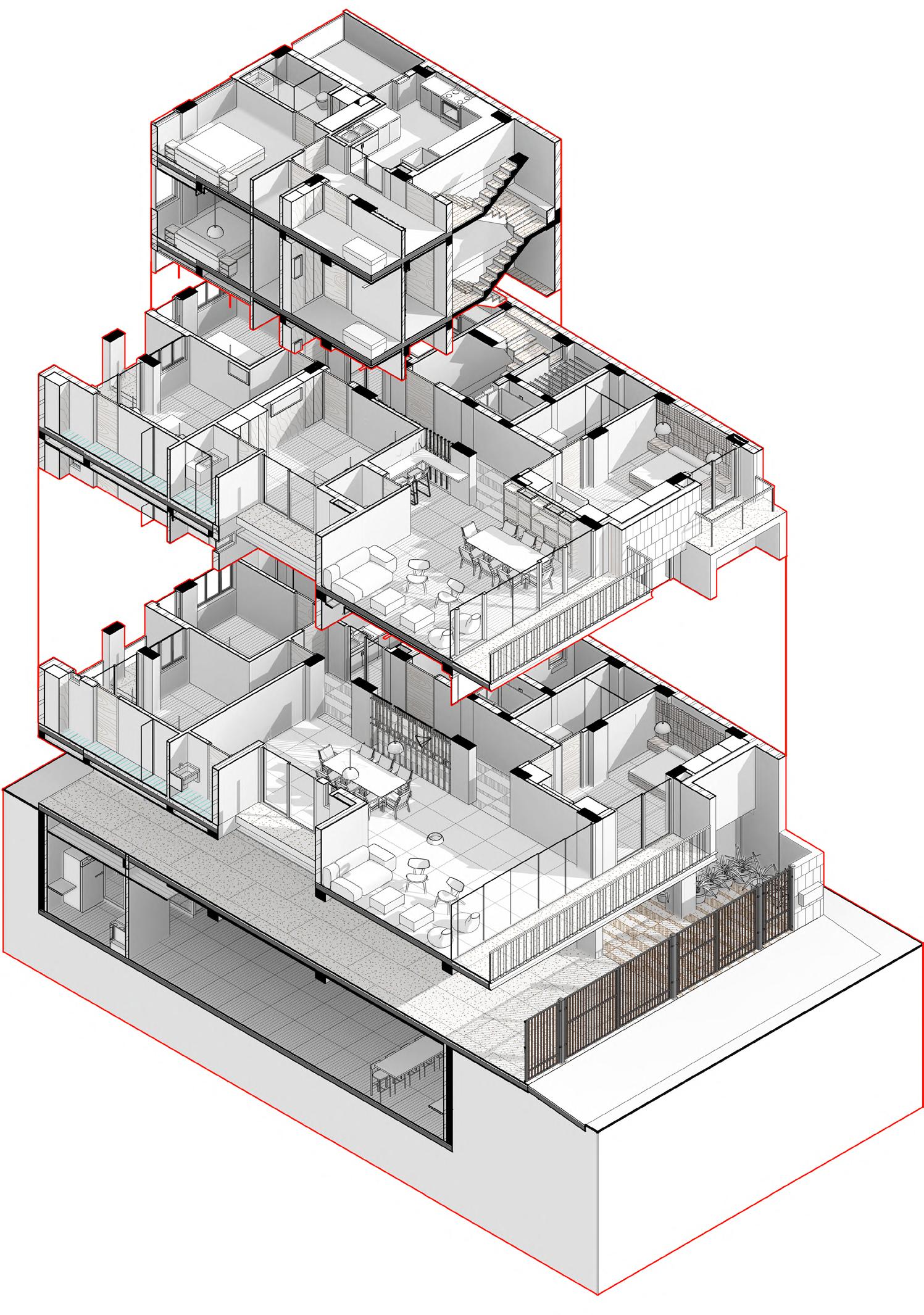
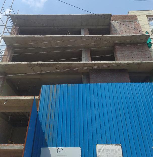
DEFENCE COLONY RESIDENCE, DELHI
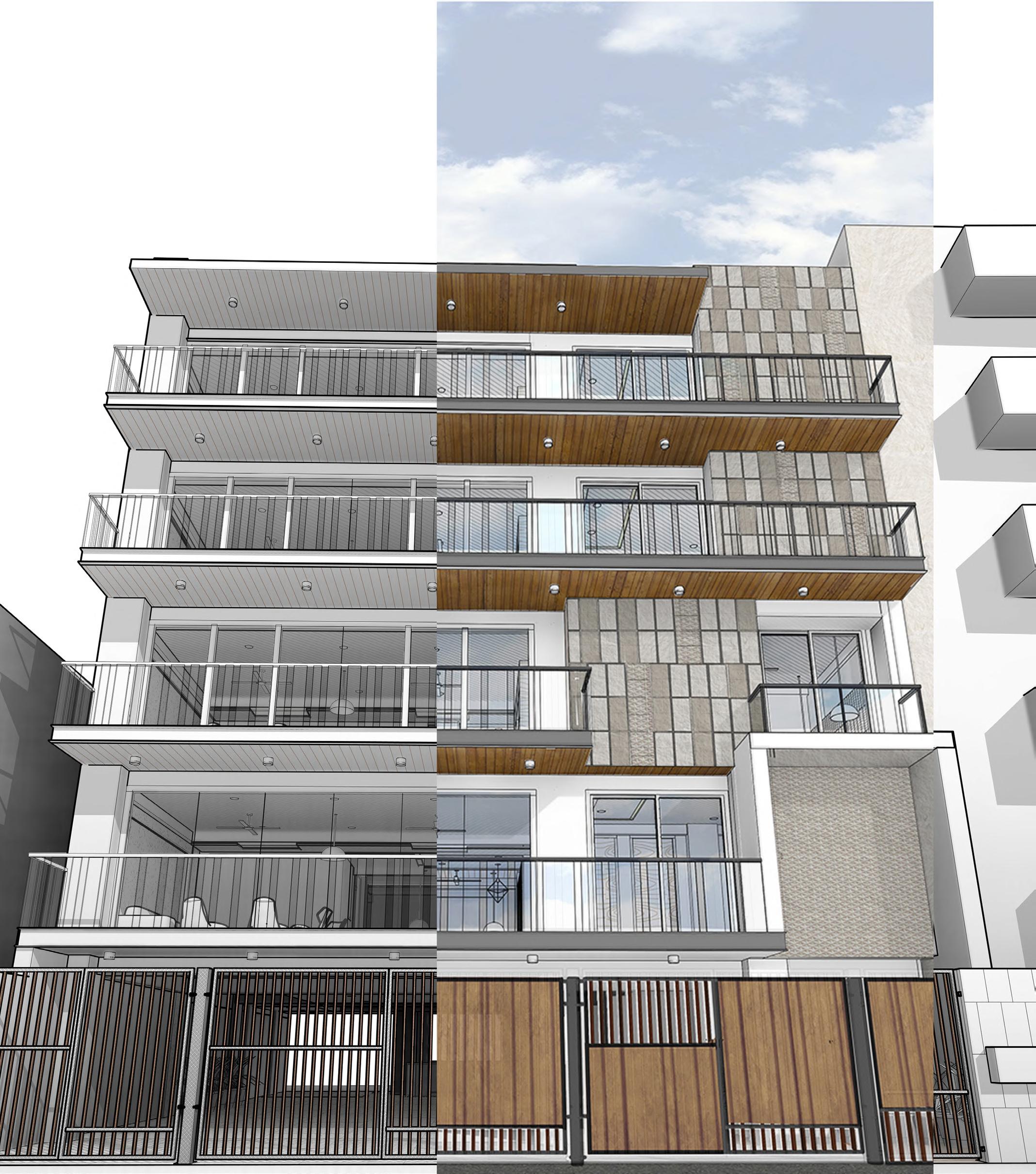
2020-2022
Professional Project
Private Residence ; Site Area : 300 sqm
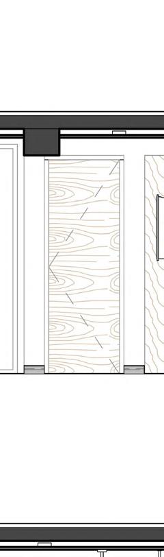
Consisting of 4 apartments elevated above a parking level, the property is hemmed in by neighbors on both sides. The 16m width of the building is its only source of light at both ends. The floor plans of the apartments are reductive, with primary services concentrated in a core on one side of the building, including the staircase, elevator, and the kitchen. To allow maximum light and ventilation cutouts are provided in he stilt floor for basement ventilation. A central cutout provides light to all floors. Series of lines and patterned finishes tie the other monotonous building to a form an entity of its own.
WOODEN PATTERNS
PATTERNED GATE GRILLS
Pattern systems in flooring system on floors, walls and facades and handrails in different materials but keeping the same vocabulary.
Cutouts for Ventilation
The use of BIM modelling enabled this project to have precise material takeoffs and improved scheduling.
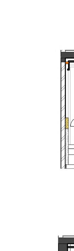
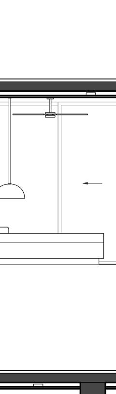


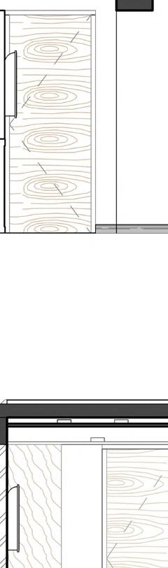
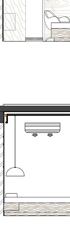
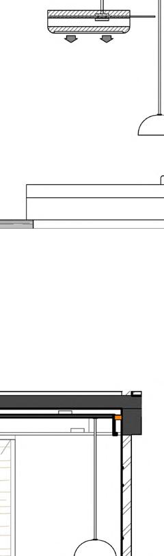
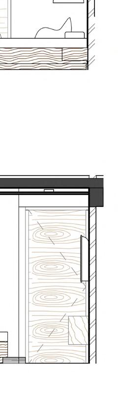
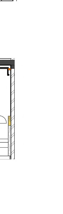
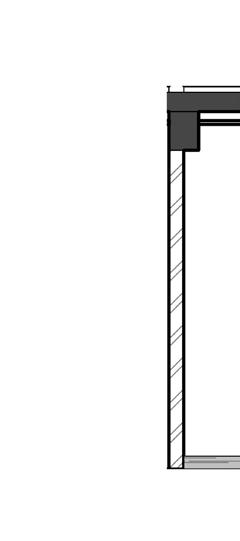
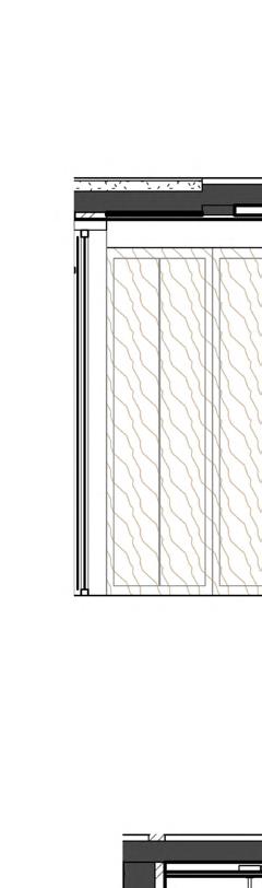
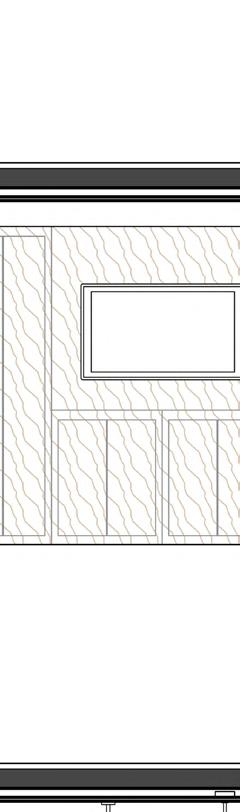
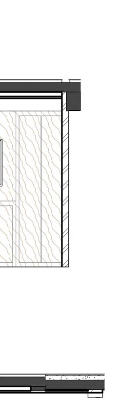
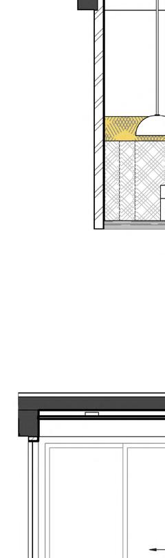
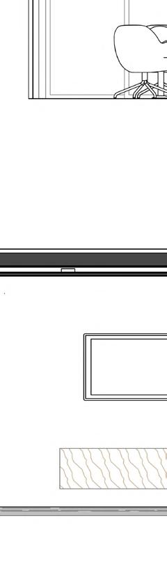
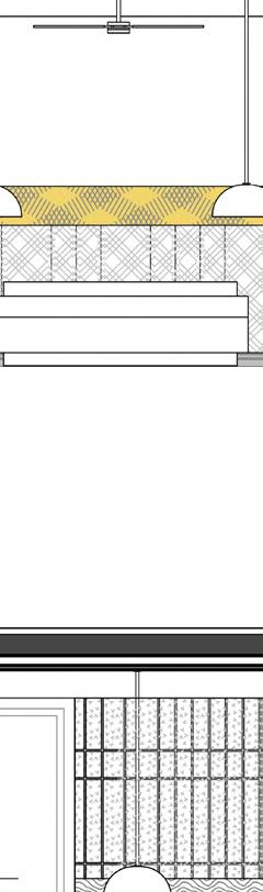
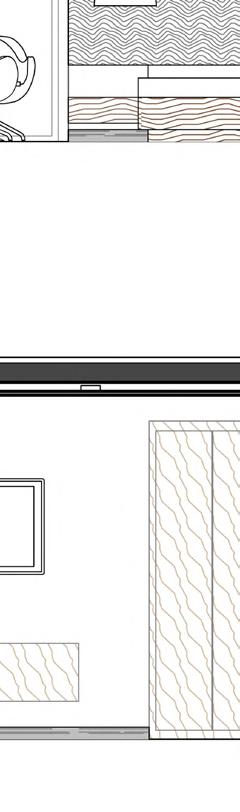
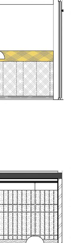
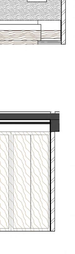
Plain False Ceiling White paint with plaster Plain False Ceiling B.O.S. +2775 B.O.B +2475 White paint with Plain False Ceiling Plain False Ceiling Wooden Ceiling B.O.B +2475 Wooden Ceiling as/design 300 FFL ±0 B.O.B +2475 B.O.S. +2775 Cabinet as/design Wall Washer 100 mm high Black stone Skirtng White paint with plaster FFL ±0 300450 B.O.S. +2775 B.O.B +2475 FFL ±0 550 300 200 150 2775 White paint with plaster Plain False Ceiling Wall Washer Accent Paint with wall grooves in plaster Wooden Panel as/design Wall hung side cabinets as/design Vertival Grooves @125 mm c/c 100 mm high Black stone Skirtng D1 B.O.S. +2775 B.O.B +2475 FFL ±0 300450 1725 200 100 2775 150200 2125 300 White paint with plaster Plain False Ceiling Wall Washer Wall hung side cabinets as/design 100 mm high Black stone Skirtng Wall hung Cabinet as/selection B.O.S. +2775 B.O.B +2475 2475 200 100 White paint with plaster Plain False Ceiling Wall hung side cabinets as/design 100 mm high Black stone Skirtng Cabinets 100 200450 FFL ±0 PROJECT : CLIENT : DRAWING TITLEARCHITECTURAL DESIGN CONSULTANT : All rights reserved. No part of this document may be reproduced or utilized in any form, without prior written authorization by Studio Next PROJECT NO: DRAWN/CHECKED: STRUCTURAL CONSULTANT: MEP CONSULTANT: 2020002 A. Jain/ T. Kumar Elevation 4A Elevation 4C 1 : 50 Elevation 5A 5 1 : 50 Elevation 5B 6 1 : 50 Elevation 5C 7 1 : 50 Elevation 5D 8 REVISION SCHEDULE REVDATEREMARKS D11 D2 350650275 1200 300 Cabinet as/design White paint with plaster 100 mm high Black stone Skirtng Plain False Ceiling Wooden Ceiling as/design Wall Washer Leather Finish as/selection Leather Finish with accent colour as/selection 100 mm high Black stone Skirtng 100 mm high recessed Black stone Skirtng White paint with plaster Plain False Ceiling B.O.S. +2775 B.O.B +2475 FFL ±0 100 200 1425 1050 2775 White paint with plaster Plain False Ceiling Cabinet as/design D1 Cabinet as/design White paint with plaster Plain False Ceiling Wooden Ceiling as/design Wall Washer Leather Finish as/selection Leather Finish with accent colour as/selection 100 mm high Black stone Skirtng 100 mm high recessed Black stone Skirtng White paint with plaster B.O.S. +2775 B.O.B +2475 FFL ±0 2475 200100 2775 Leather Finish as/selection Leather Finish with accent colour as/selection Wall Washer 2775 White paint with plaster 100 mm high reccesed Black stone Skirtng Wooden Ceiling as/design FFL ±0 B.O.B +2675 100 900 275 1200 300 FFL ±0 B.O.B +2475 B.O.S. +2775 D2 Cabinet as/design White paint with plaster Plain False Ceiling Wall Washer 100 mm high Black stone Skirtng White paint with plaster B.O.S. +2775 B.O.B +2475 FFL ±0 300450 1725 300 2775 D7 B.O.S. +2775 B.O.B +2475 FFL ±0 100 200 1275 550 300 200 150 2775 White paint with plaster Plain False Ceiling Wall Washer Accent Paint with wall grooves in plaster as/desgn Wooden Panel as/design Wall hung side cabinets as/design 375 200 600 100 Vertival Grooves @125 mm c/c 100 mm high Black stone Skirtng D1 B.O.S. +2775 B.O.B +2475 FFL ±0 300450 1725 200 100 2775 150200 2125 300 White paint with plaster Plain False Ceiling Wall Washer Wall hung side cabinets as/design 100 mm high Black stone Skirtng Wall hung Cabinet as/selection B.O.S. +2775 B.O.B +2475 2475 200 100 White paint with plaster Plain False Ceiling Wall hung side cabinets as/design 100 mm high Black stone Skirtng Cabinets 100 200450 FFL ±0 PROJECT : CLIENT : DRAWING TITLEARCHITECTURAL DESIGN CONSULTANT : PROJECT NO: DRAWN/CHECKED: STRUCTURAL CONSULTANT: MEP CONSULTANT: PRIFACTOR Private residence Mr. Rajeev Interior Details 2020002 A. Jain/ T. Kumar 1 : 50 Elevation 4A 1 1 : 50 Elevation 4B 2 1 : 50 Elevation 4C 3 1 : 50 Elevation 4D 4 1 : 50 Elevation 5A 5 1 : 50 Elevation 5B 6 1 : 50 Elevation 5C 7 1 : 50 Elevation 5D 8 REVISION SCHEDULE REVDATEREMARKS
UP DN 1 2 3 4 5 7 8 9 A B C D E G 6 1800 1600 1800 1780 2470 1800 2000 3250 4100 3325 17251450 2720 ROAD 19880 A13 A A12 Rear A16 D A11 Front A14 B A15 C A32 ST01 F SERVICE LANE D7 CUTOUT ABOVE D1 D1 D2 D3 D2 D11 D8 D2 V1 V2 V2 W1 D9 DW7 DW6 BAR CUTOUT NICHE FOR DISPLAY 1.5m (5') WIDE BALCONY 1000 mm high parapet wall CURTAIN SYSTEM AS/ DESIGN 200mmx200mm cutout in wall for chimney pipe below B.O.B 400 T = R = W= 175 275 1000 LIFT 1500 X 1500 (5' x 5') 1500 970530 600 1200300 2735 W3 V1 V1 D1 D1 D4 D7 R1 R1 W2 D2 230+75 mm brickwork lvl+150 2460 1850 1800 as/lift specs openeing 755895 2320 3115 1500 230 2020 585 200 1150 975600 1778 1488 600 600 200 3820 3155 3770 3238 3940 5295 1050 250 300 750 250 600 600 800 900 1663 600 1858 1760450 900 1430 R2 1500 1625 150 230 115 3135 PROJECT : CLIENT : DRAWING TITLEARCHITECTURAL DESIGN CONSULTANT B4-129,First Floor SAFDARJUNG ENCLAVE, NEW DELHI arch@studionext.co.in+91-11-26103770 s t u d i o n e t planning architecture design © Studio Next All rights reserved. No part of this document may be reproduced or utilized in any form, without prior written authorization by Studio Next SCALE: PROJECT NO: DATE: DRAWN/CHECKED: x STRUCTURAL CONSULTANT: MEP CONSULTANT: PRIFACTOR 1 75 Private residence Mr. Rajeev Shukla Second Floor Working Plan C-570 Defence Colony New Delhi 13/06/21 2020002 A. Jain/ T. Kumar A06 Type Opening Height MaterialNotes DW12850Wood DW23150Wood DW33150Wood DW62475UPVCSliding Dooor System Type Mark Opening Width Opening Height Sill Height Head Height Material V145075017252475UPVC V290045020252475UPVC V345075016002350UPVC W1165015759002475UPVC W290015759002475UPVC W3145015759002475UPVC W4450150011752675UPVC Type Opening Width Opening Height MaterialNotes D110002475Wood D29002475Wood D312002475Wood D48002475Wood D59002350Wood D5a9002350WoodDoor with Ventilator Above D623502475UPVCSliding Door D719502475UPVCSliding Door D816502475WoodSliding Door D9750 UPVCAccess Door with Window Above D1010002150UPVCTerrace Door@ 150mm from FFL D1123502675UPVCSliding Door DW71425 UPVCDoor Window With Ventilator Door/Window Schedule NOTES: 1. ALL DIMENSIONS ARE IN MM UNLESS MENTIONED OTHERWISE.ALL LEVELS INDICATED ARE IN MM UNLESS MENTIONED OTHERWISE. 2. DIMENSIONS / LEVELS INDICATED ARE UNFINISHED UNLESS OTHERWISE SPECIFIED. 3. ONLY WRITTEN DIMENSIONS TO BE FOLLOWED. DO NOT SCALE THE DRAWING. 4. ELEVATION LEVELS & DIMENSIONS SHOWN TO BE VERIFIED AT SITE BEFORE COMMENCEMENT OF WORK. ANY DISCREPANCIES, IF NOTED, SHOULD BE BROUGHT TO THE ATTENTION OF ARCHITECT PRIOR TO COMMENCEMENT OF WORK. REVISION SCHEDULE REVDATEREMARKS R114.06.21As/Plan R224.06.21Toilet Layouts eqeq 995 2075 2075 2075 900 750750 eq eq eq eq 600 1795 900 900600 eqeqeqeqeq 300 2675 2675 B.O.B +2475 B.O.B +2475 B.O.B +2475 2725 2725 B.O.B +2475 B.O.B +2475 2675 2725 B.O.B +2475 2675 2675 2675 B.O.B +2475 eqeqeqeqeqeq 750 300 750 1200350 TRAPDOOR 1450X750 750 1200 1175 1175450 1555 1800 1800 1800 eq eq 2150 2000 2000 2000 1005 eqeq 695 1300 1300 675 2675 525 835 150 525 1275 525 B.O.B +2475 5501035 1035550 890 675 400 675 650 650 370 B.O.B +2475 1500 1350 eq eq 500 2010 700 850850 qeqeqe 450 1350 1000 1050 600 700 600 150 False Ceiling along Bottom of Landing Beam 875 875 875 875 eq eq 900 900 1000 1655 500 525975 975525 eqeq 625 eq eq 625600 900 1727 eq eq 750300 600 600 eq eq eq 300 Grating at Landing level 370 370 ALIGN LIGHT WITH BATHROOM WALL Under Counter Light Wall mounted Uplights Wooden Finish Ceiling Wall Washer Cassette Unit 150mm Grill Wooden Finish Ceiling 1950 2185 Back Lit Bed Panel Plaster and Paint as/selection Plain False Ceiling Wooden Ceiling SYM Type of Ceiling Fan SYM Description Pendant Light Surface Mount Circular Light Recessed Circular Light 75 mm wide Recessed Strip Light Diffuser Strip Light with Wall Washer Under Counter Strip Light Uplight Linear Light SYM Description Surface Mount Linear Striplight PROJECT : CLIENT : DRAWING TITLEARCHITECTURAL DESIGN CONSULTANT NEW DELHI arch@studionext.co.in+91-11-26103770 s t u d i o n e t planning architecture design Studio Next rights reserved. No part of this document may be reproduced or utilized in any form, without prior written authorization by Studio Next SCALE: PROJECT NO: DATE: DRAWN/CHECKED: x STRUCTURAL CONSULTANT: MEP CONSULTANT: PRIFACTOR ENGINEERS Ideate Innovate Implement District Centre Laxmi Nagar, Tel: +91 011-45541858, 1 75 Private residence Mr. Rajeev Shukla Typical Floor RCP and Lighting Layout C-570 Defence Colony New Delhi 10/02/201 2020002 A. Jain/ T. Kumar A23 NOTES: 1. ALL DIMENSIONS ARE IN MM UNLESS MENTIONED OTHERWISE.ALL LEVELS INDICATED ARE IN MM UNLESS MENTIONED OTHERWISE. 2. DIMENSIONS / LEVELS INDICATED ARE UNFINISHED UNLESS OTHERWISE SPECIFIED. 3. ONLY WRITTEN DIMENSIONS TO BE FOLLOWED. DO NOT SCALE THE DRAWING. 4. ELEVATION LEVELS & DIMENSIONS SHOWN TO BE VERIFIED AT SITE BEFORE COMMENCEMENT OF WORK. ANY DISCREPANCIES, IF NOTED, SHOULD BE BROUGHT TO THE ATTENTION OF ARCHITECT PRIOR TO COMMENCEMENT OF WORK. REVISION SCHEDULE REVDATEREMARKS UP 1 2 3 E G F A33 ST02 1000 9T @ 275 2475 1620 1320 10T @ 275 2750 1025 1000751000 155 455 3 A33 T = R = W= 175 275 1000 Base Plate as /structure 20mm thk. Marble Finish Tread Dry clad fixing 300mmx1000mm Central Sringer Beam as/structure 25 25 275 MS Plate as/structure First Floor Lvl 3100 1 2 275 25 7510075 75 mm extension in MS Base Plate from tread edge 25mm dia solid MS Pipe as railing Marble Finish Tread Dry clad fixing 300mmx1000mm © Studio Next All rights reserved. No part of this document may be reproduced or utilized in any form, without prior written authorization by Studio Next 1 50 ST02 Plan 1 1 : 15 MS Riser Detail 4 1 : 10 ST02 Railing Detail 3 UP 1 2 3 E G F A33 ST02 1000 9T @ 275 2475 1620 1320 10T @ 275 2750 1025 1000751000 155 455 3 A33 T = R = W= 175 275 1000 Base Plate as /structure 20mm thk. Marble Finish Tread Dry clad fixing 300mmx1000mm Central Sringer Beam as/structure 25 25 275 MS Plate as/structure First Floor Lvl 3100 1 2 275 25 7510075 75 mm extension in MS Base Plate from tread edge 25mm dia solid MS Pipe as railing Marble Finish Tread Dry clad fixing 300mmx1000mm © Studio Next All rights reserved. No part of this document may be reproduced or utilized in any form, without prior written authorization by Studio Next 1 : 50 ST02 Plan 1 1 15 MS Riser Detail 4 1 : 10 ST02 Railing Detail 3 UP 1 2 3 E G F A33 ST02 1000 9T @ 275 2475 1620 1320 10T @ 275 2750 1025 1000751000 155 455 3 A33 T = R = W= 175 275 1000 Base Plate as /structure 20mm thk. Marble Finish Tread Dry clad fixing 300mmx1000mm Central Sringer Beam as/structure 25 25 275 MS Plate as/structure First Floor Lvl 3100 1 2 Basement Lvl -3425 Stilt Lvl 250 4 A33 10 equal risers 1750 11 equal risers 1925 25mm dia solid MS Pipe as railing 2850 3675 275 25 7510075 75 mm extension in MS Base Plate from tread edge 25mm dia solid MS Pipe as railing Marble Finish Tread Dry clad fixing 300mmx1000mm © Studio Next All rights reserved. No part of this document may be reproduced or utilized in any form, without prior written authorization by Studio Next 1 50 ST02 Plan 1 1 : 15 MS Riser Detail 4 1 50 ST02 Section 2 1 : 10 ST02 Railing Detail 3 MS Staircase 3D View 5 NOTES: 1. ALL DIMENSIONS ARE IN MM UNLESS MENTIONED OTHERWISE.ALL LEVELS INDICATED ARE IN MM UNLESS MENTIONED OTHERWISE. 2. DIMENSIONS / LEVELS INDICATED ARE UNFINISHED UNLESS OTHERWISE SPECIFIED. 3. ONLY WRITTEN DIMENSIONS TO BE FOLLOWED. DO NOT SCALE THE DRAWING. 4. ELEVATION LEVELS & DIMENSIONS SHOWN TO BE VERIFIED AT SITE BEFORE COMMENCEMENT OF WORK. ANY DISCREPANCIES, IF NOTED, SHOULD BE BROUGHT TO THE ATTENTION OF UP 1 2 3 E G F A33 ST02 1000 9T @ 275 2475 1620 1320 10T @ 275 2750 1025 1000751000 155 455 3 A33 T = R = W= 175 275 1000 Base Plate as /structure 20mm thk. Marble Finish Tread Dry clad fixing 300mmx1000mm Central Sringer Beam as/structure 25 25 275 MS Plate as/structure 1 2 275 25 7510075 75 mm extension in MS Base Plate from tread edge 25mm dia solid MS Pipe as railing Marble Finish Tread Dry clad fixing 300mmx1000mm © Studio Next All rights reserved. No part of this document may be reproduced or utilized in any form, without prior written authorization by Studio Next 1 : 50 ST02 Plan 1 MS Riser Detail 4 1 : 10 ST02 Railing Detail 3
Typical Floor RCP
Typical Floor Plan
DENMAN RESIDENCE, CANBERRA
StudioNext,Collaboration with Hyperspace
720 720 820 820 820 720 720 6 2 2 5 0 623 00 623 5 0 624 00 624 5 0 625 00 625 5 0 622 50 623 00 623 50 624 00 624 50 625 00 625.50 1 DA 301 DA 201 DA 200 1 DA 201 1 DA 200 LRG KITCHEN 4.1 X 2.8M 2 DA 301 GARAGE 6.0 X 6.0M 1300MM WIDE CORRIDOR FAMILY/ DINING 9X 4.4M HOME THEATRE 3.6 X 3.9 M LAUNDRY 1.6 X 3.6 M FAMILY BATH 2.25X3.6 M BED3 3.55 X 3.0 M BED2 3.5 X 3.0 M ENS. 1.65 X 2.7 M M. BED 4 X 4 M SUNKEN LOUNGE 3.4 X 4.6 M 1100 MM WIDE CORRIDOR FSL 623.200 FSL 624.000 FSL 624.900 BED4 3.62 X 3.0 M KITCHEN BENCH/ BRKFST BAR 2500X800 ALFRESCO 3.1X3.07 M DRIVEWAY 15.29% REAR SETBACK 3000 BUTLER'S PANTRY 1.5X 2.43 S D E S T B A C K 3000 SIDE SETBACK 1500 ENS 2 2.5 X 1.7 M TIMBER SCREEN ENTRANCE 2.59X 2.09 M NICHE@ENTRY OVN LINEN 1500MM PORCH 5.5 SQM BULKHEAD TV WALLWITH NICHES 12060 6100 180 GARAGE SETBACK 5500 1 WIR 1.65 X 2.4 M AREA SUMMARY BLOCK AREA: 510.00M2 Garage + Living: 245.5M2 Alfresco: 9.9M2 Porch: 5.2M2 TOTAL: 260.6M2 POOJA CUPBOARD 90100090500 SW1515 SW1515 SW1515 AW0612 SW1515 AW 3P 2124 AW0921 AW0921 AW 4P 2124 HL AW0621 700900 STORAGE STORAGE AW0912 STORAGE FSL 623.680 1020 500 1100 61 2 3 4 5 FEATURE BULK HEAD WITH LIGHTS OPTIONAL SKYLIGHT OPTIONAL SOLARTUBE OPTIONAL SKYLIGHT FEATURE CEILING RECESS WITH LIGHTS 1 2 SW1215 RAIN WATER TANKS CAPACITY 4000L CLOTHES DRYING AREA 5 BOUNDARY 140 00' 30.00M BOUNDARY 140 00' 30.00M BOUNDARY 76 00' 17.00M BOUNDARY 76 00' 17.00M NEIGHBOURING BLOCK 20 NEIGHBOURING BLOCK 18 FENCE FENCE EXISTING VERGE CROSSING LETTER BOX AS PER OWNERS SELECTION FRONT LANDSCAPE TO NATURAL GRADE SIDE LANDSCAPE TO NATURAL GRADE SIDE LANDSCAPE TO NATURAL GRADE REAR LANDSCAPE TO NATURAL GRADE WT1 WT1 WT1 WT1 WT7 WT7 WT7 WT1 WT1 WT1 WT8 WT1 WT1 WT1 WT1 WT1 WT1 WT1 WT1 WT1 PPOS FSL 623.925 FENCE @ 1800 FROM NGL LAND TO BE LEVELLED TO SLOPE ALONG THE NATURAL FALL OF THE SITE LAND TO BE LEVELLED TO SLOPE ALONG THE NATURAL FALL OF THE SITE 450 450 450 WT12 WT12 WT12 WT12 LOCATION OF WATER METER /TBC CONFIRMED ON SITE. KEEP AN AREA OF 1.0M AROUND THE WM AS PER THE NATURAL GROUND LEVEL TO ENSURE ICON ACCESS STEPPED RETAINING WALL REAR SETBACK 3000 1900900900 2200 900090 2980 250 4170 9010009041090 3400 90 3600 250500 FRONT SETBACK 4000 250 4170 90 190 1200 11090 480 2400 520 90 450 2100 1050250 1000 C 250165090 4000 90 12480 9020082015202500810250 250 1650 90 3050 900 5090 5330 1100 90 1600 90 810 90160 1000 4855 220 L 250165090800900 60 90 2235 90 100 900 2535 90650900 50 90 40 900 90 90 660720112882 6015 235 REAR SETBACK 3000 250 3500 90 2235 90 1200 1500835 90 700900 90 1500 1960 250 6015 220 5575 3024 250 870 500 110 2400 270 1905 465 680 4800 505 1221 250 3900 90 645 1445 90 6115 220 1221 1016 450 L 250 2430 90 1660 450 2466 90 1100 90 3600 250 250 3600 9060 800856 90 400 3060 500 90 735720975250 250 690 1500 636 250 4020 90 1100 90 1568 90 1942 250 6100 250 4020 90 1100 90 880 720 2000 250 250 1480 720 540 90 470 720 90 1100 90 3600 250 3024 3076 250 1840 900 90 2380 90 3600 250 FSL 623.850 FSL 623.850 3 1 3 FSL 624.350 FSL 624.350 740 1500 750 750 DRAWING PROJECT No. PROJECT NOTES This drawing copyright and remains the property of Hyperspac Designs Pty Ltd. This drawing for development application or building approva purposes only and not for construction unless noted otherwise Check and verify all dimensions prior to commencement of works. Any discrepancies or inconsistencies or departure from issued nformation are to be clarified prior to ordering of material an execution of related works.This drawing is to be read and not measured. Written dimensions take precedence over scaled dimensions. This drawing is to be read in conjunction with all other contract documents inclusive of all schedules, specifications other consultant documentation and trade requirements. All construction to be as per relevant local regulations, NCC and Australian standards. SCALE DATE DWG 1 : 50 @ A1 2057 14 GIORDANO STREET BLOCK 19 SECTION 14 DENMAN GROUND FLOOR LAYOUT 30/11/2020 DA 100 SUDHAR SRINIVASAN ESWARI SUDHAR REV DESCRIPTION DATE A CONCEPT LAYOUT 11.12.2020 B CONCEPT LAYOUT REV01 13.12.2020 C CONCEPT LAYOUT REV02 10.01.2021 LOWER GROUND 624.000 m ROOF 629.000 m GARAGE 623.200 m ROOF EAVE 627.500 m UPPER GROUND 624.900 m DA 301 A B BUILDING ENVOLOPE 3500 4500 1800@NGL FENCE BUILDING ENVOLOPE 3500 45 00 1800@NGL FENCE 900 RL 626.910 RL 627.474 RL 627.482 RL 629.082 RL 629.082 RL 628.016 RL 629.535 RL 629.535 RL 627.700 FSL 624.000 FSL 624.900 LIVING DINIG MASTER BEDROOM CEILING 2700 CEILING 2700 CONTRACTOR TO ENSURE MAXIMUM 1M CUT AT BOUNDARY FROM NGL 300 NGL 1 50 DA 100 Section 1 1 NOTE REV
2020-2022
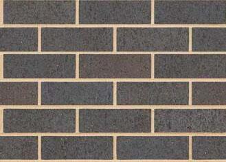


9am 3pm G G G S S W W W SW SW SW D D D T T E E 6 2 2 5 0 623 00 623 5 0 624 00 624 5 0 625 00 625 5 0 6 2 2 5 0 6 2 3 0 0 623 50 624 00 624 50 625 00 625.50 N E 1 0 7600 CANBERRA PREVAILING WINDS Canberra's prevailing winds are from the northwest, and strengthen during the afternoon. Autumn and spring months are 50% calm in the mornings. Summer winds swing from west to north, with some easterly winds. Southerly afternoon winter winds are a consideration for design. The climate is cool temperate with an occasional hot day. Solar access is desirable from autumn to spring. BOUNDARY SUN PATH MAJOR CONTOURS MINOR CONTOURS ELECTRICAL FENCE TELECOMMUNICATION LINE DATA LINE STORM WATER LINE WATER SEWER GAS STREET LIGHT BOLLARD ELECTRICITY POLE SEWER MANHOLE STORM WATER MANHOLE WATER METER PIT COMMUNICATIONS PIT FIRE HYDRANT GROUND LEVEL SETBACK FOOTPATH LP B PP SMH SWMH WM C FH SERVICES PIT PROPOSED TREE REGULATED TREE UPPER LEVEL SETBACK NORTH WNTERSUNS T 1 UN WNTERSUNRSE JUNE SUMMERSUNSE 1DECEMBER SUMMERSUNRISE 21DECEM ER A B 1 2 BOUNDARY 14 00' 30.00M BOUNDARY 14 00' 30.00M BOUNDARY 76 0 00' 17.00M BOUNDARY 76 00' 17.00M PROPOSED DRIVEWAY EXISTING VERGE CROSSING LETTER BOX AS PER OWNERS SELECTION LOCATION OF WATER METER /TBC CONFIRMED ON SITE. KEEP AN AREA OF 1.0M AROUND THE WM AS PER THE NATURAL GROUND LEVEL TO ENSURE ICON ACCESS GARAGE ENTRY LEVEL PROPOSED RESIDENCE BLOCK 19 SECTION 14 DENMAN FSL +623.20 FSL +624.90 6m X 6.1m POS 12.06 X 6.1m POS RAIN WATER TANKS CAPACITY 4000L CLOTHES DRYING AREA GIORDANO STREET NEIGHBOURING BLOCK 20 NEIGHBOURING BLOCK 18 FSL +624.00 FRONT LANDSCAPE TO NATURAL GRADE REAR LANDSCAPE TO NATURAL GRADE GRADETOSLOPE SLOPEUPFROMHOUSE NOTES e Designs Pty Ltd. purposes only and not for construction unless noted otherwise nformation are to be clarified prior to ordering of material an easured. Written dimensions take precedence over scaled other contract documents inclusive of all schedules, specificat truction to be as per relevant local regulations, NCC and BLOCK 19 SECTION 14 DENMAN SUDHAR SRINIVASAN ESWARI SUDHAR Wall Type Family and Type Description Fire Rating WT1 Basic Wall: HSD Timber Veneer Wall 250mm BrickEXTERNAL WALL WT6 Basic Wall: HSD Light Weight Weathertex 150mmGENERIC WALL 150 WT7 Basic Wall: HSD DOUBLE BRICK OUTDOOR WALLEXTERNAL LANDSCAPE WALL WT8 Basic Wall: HSD Render on Timber Veneer Wall 250mm BricK EXTERNAL WALL WT10 Basic Wall: HSD PLASTER WALL 90MM INTERNAL WALL WT11 Basic Wall: HSD COLOUR BOND FENCE BOUNDARY FENCE WT12 Basic Wall: HSD Concrete Sleeper Retaiining WallEXTERNAL LANDSCAPE WALL Type Mark Width Height Description Count AW0612 1200 600 1 AW0912 900 1200 1 AW0921 900 2100 2 AW 4P 21242400 2100 1 HL AW06212100 600 1 AW 3P 21242400 2100 1 SW1215 1500 1200 SLIDING WINDOW 1 SW1515 1500 1500 SLIDING WINDOW 4 1 : 100 DA 200 SITE PLAN 1 REV DESCRIPTION DATE WALL TYPES WINDOW SCHEDULE IMPORTANT NOTE: THE COUNTURS AND THE SITE LEVELS HAVE BEEN DEVELOPED FROM THE BLOCK DETAIL PLANS ISSUED BY SLA AND THEREFORE INDICATIVE ONLY. NO SURVEY WAS ISSUED BY THE BUILDER OR CLIENT FOR DESIGN DEVELOPMENT. BUILDER NEEDS TO CONFIRM THE LEVELS THROUGH A CERITFIED SURVEYOR AND DETRMINE THE ACCURATE CUTS AND FILLS ON SITE. DRAWING PROJECT No. PROJECT NOTES This drawing copyright and remains the property of Hyperspac Designs Pty Ltd. Check and verify all dimensions prior commencement of works. Any discrepancies or inconsistencies or departure from issued nformation are to be clarified prior to ordering of material an execution related works.This drawing to be read and not measured. Written dimensions take precedence over scaled other contract documents inclusive of all schedules, specificat other consultant documentation and trade requirements. All construction to be as per relevant local regulations, NCC and Australian standards. SCALE DATE DWG 1 1 @ A1 2057 14 GIORDANO STREET BLOCK 19 SECTION 14 DENMAN VIEW AND MATERIALS 30/11/2020 DA 800 SUDHAR SRINIVASAN ESWARI SUDHAR THE RENDERED IMAGES ARE ARTISTIC IMPRESSIONS ONLY. THE FINAL MATERIAL SELECTIONS ARE AS PER CLIENTS AGREEMENT WITH BUILDER FRONT GARAGE WALL IN 'AUSTRAL BLUE GUM WT2 WHITE RENDER FOR FACADE DULUX ANTIQUE WHITE(US) OR EQUIVALENT. MATCH FASCIA COLOUR TO THE FRONT RENDER. TIMBER DOOR WITH SINGLE GLAZED PANEL OR EQUIVALENT GREY CONCRETE OR EQUIVALENT FOR DRIVEWAY WITH CROSSBANDING COLOUR BOND MONUMENT FOR ROOF. MATCH THE WINDOW FRAME COLOUR TO THE DARK GREY OF ROOF. 1 1 View from South East 1 1 1 View from South 2 REV DESCRIPTION DATE LOWER GROUND 624.000 m ROOF 629.000 m DA 301 GARAGE 623.200 m ROOF EAVE 627.500 m UPPER GROUND 624.900 m 1 2 SW1515 SW1515 450 300 165 300 BUILDING ENVOLOPE 3500 BUILDING ENVOLOPE 3500 RL 626.910 RL 627.910 RL 629.535 RL 627.910 RL 626.910 1800@NGL FENCE 1800@NGL FENCE WT1 WT1 WT11 WT1 WT12 LOWER GROUND 624.000 m ROOF 629.000 m GARAGE 623.200 m ROOF EAVE 627.500 m 1 2 452 450 450 165 300 BUILDING ENVOLOPE 3500 BUILDING ENVOLOPE 3500 1800@NGL FENCE 1800@NGL FENCE WT12 WT1 WT1 WT8 WT1 WT11 WT6 DRAWING PROJECT NOTES This drawing copyright and remains the property Hyperspac Designs Pty Ltd. Any discrepancies inconsistencies or departure from issued nformation are be clarified prior ordering of material an execution related works.This drawing read and not easured. Written dimensions take precedence over scaled 1 50 @ A1 2057 BLOCK 19 SECTION 14 DENMAN ELEVATIONS DA 201 SUDHAR SRINIVASAN ESWARI SUDHAR 1 50 DA 100 North 1 1 50 DA 100 South 2
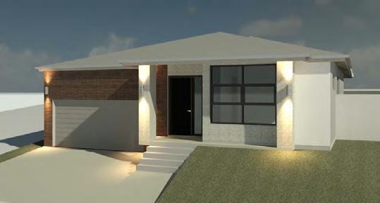
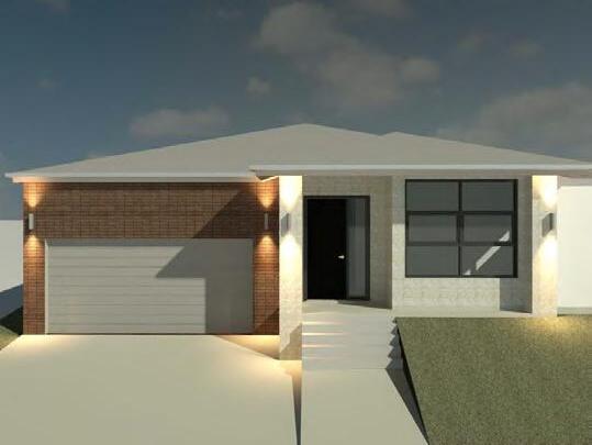
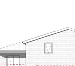
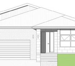
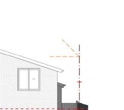
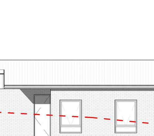
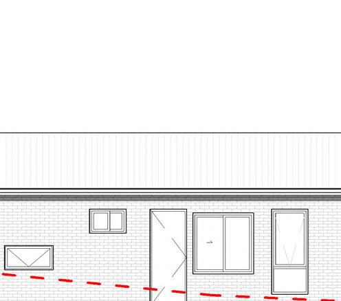
MULTIPLE SINGLE FAMILY HOMES, AUSTRALIA
StudioNext,Collaboration with Hyperspace 2020-2022
These projects include documentation, Design and BIM Management for Multiple Small Scale Family Homes and Commercial Projects in Canberra Territory.
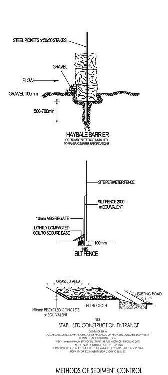
SEDIMENT CONTROL NOTES:
THE DEVELOPMENT WILL COMPLY WITH THE ENVIRONMENT PROTECTION AUTHORITY,ENVIRONMENT PROTECTION GUIDELINES FOR CONSTRUCTION AND LAND DEVELOPMENT INTHE ACT, AUGUST 2007.
ALL SEDIMENT CONTROLS MUST BE IN PLACE PRIOR TO COMMENCEMENT OF ANY BUILDING WORKS AND CHECKED DAILY.
SEDIMENT CONTROLS MUST BE RETAINED UNTIL RE-VEGETATION IS FULLY ESTABLISHED AFTER BUILDING COMPLETION TO COMPLY WITH BEST PRACTICE GUIDELINES REFERENCED ABOVE.
THE DEVELOPER/BUILDER WILL COMPLY WITH THE ACT ENVIRONMENT PROTECTION AUTHORITY, ENVIRONMENTAL PROTECTION GUIDELINES FOR CONSTRUCTION AND LAND DEVELOPMENT IN THE ACT MARCH 2011.
STORMWATER SUMPS TO BE LOCATED ON SITE DURING SITE DELIVERIES, NEIGHBOURING PROPERTIES AND PUBLIC AREAS MUST BE KEPT CLEAR.
AS A MINIMUM 1.8m HIGH TEMPORARY SITE FENCE IS TO BE PROVIDED TO SECURE THE SITE UNTIL THE 'LOCK UP' STAGE. THIS ALSO INCLUDES INSTALLATION OF APPROPRIATE SEDIMENT AND EROSION CONTROLS.
ALL BUILDING MATERIALS STORED ON SITE MUST BE WITHIN THE PROPERTY BOUNDARY AT ALL TIMES. ANY DAMAGE TO STREET TREES, TREE GUARDS OR WELLS DURING CONSTRUCTION IS THE RESPONSIBILITY OF THE PROPERTY OWNER TO REPAIR OR REINSTATE TO ORIGINAL SPECIFICATIONS.
THE LOCATION OF ANY TEMPORARY OR RE-LOCATBLE BUILDINGS/STRUCTURES IN THE VERGE IS NOT PERMITTED UNDER ACT LAW. THE DUMPING OR STORAGE OF EXCESS EARTHWORKS ON NEIGHBOURING SITES AS WELL AS PUBLIC AREAS IS STRICTLY PROHIBITED AS PER THE ACT LITTER ACT 2004
VERGE MANAGEMENT NOTES:
INSTALL 1800mm HIGH CONTINUOUS TEMPORARY FENCING AROUND VERGES AND EXISTING VEGETATION TO BE RETAINED IF PRESENT FENCING TO BE ERECTED ON COMMENCEMENT OF SITE WORK AND REMOVED UPON COMPLETION OF CONSTRUCTION AND COMMENCEMENT OF VERGE RESTORATION.
ENSURE ADEQUATE WATER IS APPLIED TO THE ROOT ZONE OF RETAINED VEGETATION THROUGHOUT CONSTRUCTION PERIOD MAKE GOOD ANY DAMAGE TO EXISTING GRASS VERGES, TREES, PATHS, KERBS, ROADWAYS TO THE SATISFACTION OF RELEVANT AUTHORITIES IF GRASS COVER ON THE VERGE NEEDS IMPROVEMENT, THE FOLLOWING REQUIREMENTS APPLY:
-LIGHTLY CULTIVATE THE SOIL TO 25mm-50mm DEPTH. CULTIVATE ONLY IN ONE DIRECTION. AVOID MAJOR ROOTS AND KEEP 1.0m CLEAR FROM TREE TRUNKS. LAY TURF OR SOW SEED OF SUITABLE DROUGHT TOLERANT SPECIES.
ANY & ALL DAMAGE CAUSED TO THE SURROUNDING PUBLIC INFRASTRUCTURE
INCLUDING STREET KERBS, STREET TREES, FOOTPATHS, KERB CROSSOVERS, VERGE (NATURE STRIP) SERVICES & ADJOINING LAND, CAUSED BY THE CONSTRUCTION OF THE RESIDENCE IS TO BE REPAIRED & REINSTATED TO ITS ORIGINAL STATE BY THE CONTRACTOR/BUILDER
CARRY OUT ALL WORK IN COMPLIANCE WITH THE RELEVANT SAA CODES OF PRACTICE IN THE BEST TRADESMAN-LIKE MANNER TO THE APPROVAL OF THE BUILDING CERTIFIER AND AUTHORITIES HAVING JURISDICTION OVER THE WORKS INCLUDING BUT NOT RESTRICTED TO:
A) ACT GOVERNMENT
B) BUILDING CODE OF AUSTRALIA AND THE ACT APPENDIX
C) ACT ELECTRICITY AND WATER
D) AS1684 TIMBER FRAMING CODE AND AS FURTHER SPECIFIED.
-REGISTERED SURVEYOR TO SETOUT THE BUILDING PRIOR TO ANY CONSTRUCTION
WORKS
-ALL LEVELS, SITE CUTS, GROUND LEVELS, FFL'S TO BE CONFIRMED ON SITE PRIOR TO THE COMMENCEMENT OF ANY WORKS (INCLUDING DRIVEWAY LEVELS
-DIMENSIONS ARE TO BE READ AND NOT SCALED OR MEASURED.FOR ANY DISCREPANCY CONFIRM FROM THE ARCHITECT PRIOR TO EXECUTION
-ALL WINDOWS TO BE AS PER ENERGY RATING REPORT
-WATER HEATER IN HOT WATER SUPPLY SYSTEM TO COMPLY WITH CLAUSE 3.12.5.6 OF THE BCA
-LIGHTING TO COMPLY WITH CLAUSE 3.12.5.5 OF THE BCA
-WET AREAS TO COMPLY WITH ALL RELEVANT CLAUSES OF THE BCA
-BRICK PIERS TO COMPLY WITH BCA AND AS4773
-DRIVEWAY TO COMPLY WITH GW/SD/DC.02 & FINISH TO COMPLY WITH ANY LEASE & DEVELOPMENT CONDITIONS AND RELEVANT LOCAL CODES
-STAIR NOSING STRIP SLIP RESISTANCE CLASSIFICATION -INDOORS P3 AND OUTDOORS P4
-LICENSED PLUMBER TO SUBMIT WORKS EXECUTED PLAN
-LICENSED ELECTRICIAN TO SUBMIT CES FORM
-SMOKE ALARMS TO BE INSTALLED IN ACCORDANCE WITH THE BCA Part 3.7.2 AND AS 3786
-TILES & FLASHINGS TO BE INSTALLED IN ACCORDANCE WITH MANUFACTURERS
SPECIFICATIONS
-PROVIDE SMOKE ALARMS IN ACCORDANCE WITH PART 3.7.2 OF THE BCA (REFER ELECTRICAL LAYOUT)
-ALUMINIUM IMPROVED FRAMES (UNLESS NOTED OTHERWISE)
-ALL TIMBER FRAMING AND CONSTRUCTION TO BE IN ACCORDANCE WITH THE LATEST TIMBER FRAMING CODE AS1684 AND BCA
-EXTERNAL WALLS TO BE BRICK VENEER UNLESS STATED ON PLANS, WHEN LIGHTWEIGHT CLADDING IS USED IT IS TO BE INSTALLED TO MANUFACTURERS
SPECIFICATIONS AND SARKED AND INSULATED AS PER THE BCA AND ATTACHED EER.
ALL INSULATION R VALUES AND WINDOW SHGC AND U-VALUES AS PER THE EER.
-ALL OPENABLE WINDOWS AND SLIDING DOORS TO HAVE -FLYSCREENS TO BE POWDERCOATED ALUMINIUM FRAMES TO MATCH WINDOWS. NOTE: METALLIC FLYSCREENS ARE REQUIRED IN BUSHFIRE PRONE AREAS
-REFER TO STRUCTURAL ENGINEER'S ATTACHED DOCUMENTATION FOR ALL STRUCTURAL DETAILS
ALL EXTERNAL WINDOWS TO HAVE BRICK ON EDGE WINDOW SILLS WITH DAMP PROOF MEMBRANE UNDER TO BCA
PROVIDE TERMITE PROTECTION TO CODE AND AS3660-2000 PARTS 1, AND 3 DESIGN
THAT 17%, DOWNHILL GRADE OF LESS THAN 12%. AT RIGHT ANGLE TO THE KERB LINE WITH MAXIMUM 10% DEVIATION A MAXIMUM OF 5.5m WIDTH, & MINIMUM OF 5m WIDTH AT THE KERB, MINIMUM 3m WIDTH AT THE FRONT BOUNDARY, & A MAXIMUM WIDTH NO GREATER THAN THE WIDTH AT KERB. OUTSIDE OF THE DRIP LINE OF MATURE TREES, & A MINIMUM OF 3m CLEAR OF S MALL & NEW STREET TREES. COMPLIANT WITH AS2890.1. COMPLIANT WITH T.A.M.S REQUIREMENTS/ADVICE.
NOTE5 RETAINING WALLS NOT SPECIFICALLY DETAILED FOUNDATION WALING REQUIRED TO RETAIN EARTH UP TO BE A MIN 230mm(th.) UP TO HEIGHT OF 750mm OF RETAINED EARTH. CAVITY WALLS USED TO RETAIN EARTH ARE TO HAVE THE LEAF ADJACENT TO THE RETAINED EARTH A MINIMUM OF 230mm THICK, TO A MAXIMUM OF 900mm OF RETAINED EARTH HEIGHT. ALL RETAINING WALL BE TO PROPERLY BONDED & PROVIDED AGRICULTURAL DRAIN TO THE EARTH SIDE OR THE WALL. FOR RETAINING WALLS ABOVE HEIGHTS OF RETAINED EARTH LISTED ABOVE SHALL REQUIRE ENGINEERING DETAILS. ALL RETAINING WALLS ARE TO COMPLY WITH PLANNING POLICY ON RETAINING WALLS & EMBANKMENTS ON RESIDENTIAL BUILDING SITES.
NOTE6: -NO INTERNAL DRAINAGE FOR PROPOSED STRUCTURE TO BE LOCATED IN SEWER EASEMENT/PIPE PROTECTION ENVELOPE. ALL WORKS DONE TO ACTEW GUIDELINES/ADVICE. ALL BUILDING WASTE TO BE COLLECTED IN HOPPER LOCATED ON SITE, RESIDENTIAL WASTE TO BE COLLECTED BY ROADSIDE PICKUP & BINS TO BE LOCATED ON SITE. METER BOX TO BE INSTALLED TO ACTEW AGL SERVICE INSTALLATION RULES. LIGHTING TO COMPLY WITH 3.12.5.5 OF THE BCA ARTIFICIAL LIGHTING MUST NOT EXCEED 514/M2. ELECTRICIAN TO CONFIRM PROIR TOCOMMENCEMENT. WATER HEATER IN HOT WATER SUPPLY SYSTEM TO COMPLY WITH 3.12.5.6 OF THE BCA. STORMWATER, SEWER WATER TIES TO BE LOCATED ON HYDRAULIC/DRAINAGE PLANS. TELSTRA GAS TIES TO BE PROVIDED BY GAS FITTER & ELECTRICIAN. 100x75 RECTANGULAR (TBC) DOWNPIPES SIZE & LOCATION
COMPLIANCE: ALL DEVELOPMENT TO COMPLY WITH ENVIROMENT PROTECTION AUTHORITY, ENVIRONMENT PROTECTION GUIDELINES FOR CONSTRUCTION AND LEND DEVELOPMENT IN THE ACT, AUG 2007
ALL FINISHED GROUND LEVELS TO THE STORM WATER PIT OR SUMP AND CONNECT TO THE STORM WATER LINE. TL
DRAWING SCALE DATE DWG NUMBER PROJECT PROJECT No. HYPERSPACE architec ture heritage planning urban design Hyperspace design pty ltd (Australia) +61404334430 e:contact @ hyper-space.com.au This drawing copyright and remains the property Hyperspace Designs Pty Ltd This drawings is for development application purposes and not for construction, unless noted otherwise @ A3 COVER SHEET NOV 2020 DA 000 2048 MICHAEL DEAN MA AND WENQIAN ZHANG BLOCK 11 SECTION 11 THROSBY 10 PERUNGA RISE THROSBY Wall Type Family and Type Description Fire Rating WT1Basic Wall: 1 HSD Timber Veneer Wall 250mm BrickEXTERNAL WALL() WT2Basic Wall: 1 HSD SCYON STRIA 325 EXTERNAL WALL WT4Basic Wall: 1 HSD PLASTER WALL 90MM INTERNAL WALL WT7Basic Wall: 1 HSD TIMBER PALING FENCE FENCE WT8Basic Wall: 1 HSD 260MM WHITE RENDER WALLGENERIC WALL 300 WT9Basic Wall: 1 HSD Render on Brick Wall 250mmEXTERNAL WALL WT10Basic Wall: HSD Concrete Sleeper Retaiining WallEXTERNAL LANDSCAPE WALL WT11Basic Wall: 1 HSD Timber Cladding Wall GENERIC WALL 100 WT12Basic Wall: 1 HSD Light Weigh Partition WallGENERIC WALL 100 Type Mark Width Height Description Count AW0609900 600 2 AW06212100 600 2 AW 2109900 2100 1 AW1209900 1200 1 AW18121200 1800 2 SW15181800 1500 3 AW21181800 2100 1 AW21181800 2100 1 SD24181800 2400 1 SDX24242400 2400 2 REVDESCRIPTION DATE BUSHFIRE AND PEST CONTROL: METALLIC FLYSCREENS ARE REQUIRED IN BUSHFIRE PRONE AREAS -REFER TO STRUCTURAL ENGINEER'S ATTACHED DOCUMENTATION FOR ALL STRUCTURAL DETAILS. ALL EXTERNAL WINDOWS TO HAVE BRICK ON EDGE WINDOW SILLS WITH DAMP PROOF MEMBRANE UNDER TO BCA PROVIDE TERMITE PROTECTION TO CODE AND AS3660-2000 PARTS 1, 2 AND 3 ENERGY NOTES -ALL INSULATION & 'R' VALUES AND WINDOWS SHGC AND VALUES AS PER THE EER REPORT. -WALL INSULATION MIN. R 2.5 -IT IS ASSUMED ALL WINDOWS, SKYLIGHTS & GLAZED DOORS ARE DOUBLE GLAZED UNLESS OTHER WISE SPECIFIED. CONSTRUCTION NOTES: -ALL CONSTRUCTION AND
STANDARDS
SITE ACTIVITIES TO BE UNDERTAKEN AS PER RELEVANT PARTS OF THE NCC AND THE AUSTRALIAN
IRRESPECTIVE OF ANY INFORMATION NOTED IN DRAWINGS.
AND EXECUTION NOTES:
FINAL SELECTION OF MATERIALS IS THE RESPONSIBILITY OF CLIENT AND/OR BUILDER, INCLUDING BUT NOT LIMITED TO PROPER INSTALLATION OF MATERIALS, NAILING, GLUING, CAULKING,INSULATING, FLASHING, ROOFING, WEATHERPROOFING AND OTHER ITEMS AND DETAILS NOTINDICATED ON THE PLANS, AND OVER WHICH THE DESIGNER HAS NO CONTROL OR RESPONSIBILITY. NOTE ALL DIMENSIONS ARE IN MILLMETERS. DIMENSIONS TAKE PREFERENCE OVER SCALE & ARE TO STRUCTURE NOT FINISH. ALL DIMENSIONS MUST BE VERIFIED ON SITE BEFORE COMMENCING ANY WORK OR MAKING ANY CONSTRUCTION DRAWINGS. USE FIGURED DIMENSIONS ONLY DO NOT SCALE OFF THE DRAWING. SURVEYOR TO CONFIRM EASEMENT LOCATIONS PRIOR TO COMMENCEMENT OF ANY WORKS. WORK SHALL COMPLY WITH THE BCA ALL RELEVANT CURRENT AUSTRALIAN STANDARDS. ANY OUTDATED STANDARDS LISTED IN THESENOTES ARE TO BE REFERED TO THE CURRENT EDITION. HYPERSPACE WILL NOT BE HELD LIABLE RESPONSIBLE IN ANY FORM BY ANY PARTY WHATSOEVER FOR ANY DESIGN OR STRUCTURAL COMPONENT, NOTATIONOR ACCURACY OF DOCUMENTATION HEREIN. CLIENT BUILDER ACCEPTS PLANS AND RESPONSIBILITY ONCE PLANS ARE ACCEPTED FOR APPROVALS. NOTE ALL LEVELS, SITE CUTS, GROUND LEVELS, FFL'S TO BE CONFIRMED ONSITE PRIOR TO THE COMMENCEMENT OF ANY WORKS. (INCLUDING DRIVEWAY LEVELS) ANY DISCREPANCIES TO BE DIRECTED TO BUILDER &/OR DESIGNER IMMEDIATELY. NOTE 4: DRIVEWAYS TO BE1.2m HORIZONTALLY CLEAR OF STORMWATER SUMPS & SERVICES. 1.5m HORIZONTALLY CLEAR OF TRANSFORMERS, BUS STOPS, LIGHT POLES. UPHILL GRADE OF LESS
NOTE1
TO ROOF. PLUMBERS SPECIFICATIONS –TO BE CONFIRMED PRIOR TO DRAINAGE. ENSURE THAT THE DEVELOPMENT COMPLIES WITH TERRITORY & MUNICIPAL SERVICES (TAMS) STATING THAT WASTE FACILITIES & MANAGEMENTASSOCIATED WITH DEVELOPMENT ARE IN ACCORDANCE WITH THE DEVELOPMENT CONTROL CODE FOR BEST PRACTICE WASTE MANAGEMENT IN THE ACT 1999.
STREET A B 2 1 GENERAL SLOPE OF SITE CONSTRUCTION FENCE ALL AROUND THE BLOCK BOUNDARY GARBAGE ENCLOSURE CUT/WASH AREA TOI EXISTING VERGE CROSSING PROPOSED DRIVEWAY CONTRACTOR TO PROVIDE MEASURES TO PREVENT RUNOFF BOUNDARY 41 30' 30.00M BOUNDARY 41 30' 30.00M BOUNDARY 48 30' 18.00M BOUNDARY 48 30' 18.00M NEIGHBOURING BLOCK 14 NEIGHBOURING BLOCK 12 BLOCK 13 SECTION 92 TAYLOR PROPOSED DWELLING DRAWING SCALE DATE DWG NUMBER PROJECT PROJECT No. HYPERSPACE architec ture heritage planning urban design Hyperspace design pty ltd (Australia) P: +61404334430 e:contact @ hyper-space.com.au This drawing is copyright and remains the property of Hyperspace Designs Pty Ltd This drawings is for development application purposes and not for construction, unless noted otherwise 1 200 @ A3 SITE ESTABLISHMENT PLAN DA 011 2031 JUDE BLOCK 13 SECTION 92 TAYLOR SODERSTEN STREET SITE CUTS & RETAINING WALLS` RETAILING WALL TO STRUCTURE ENGINEERS DESIGN SITE CUT PLUS EXCAVATION AS REQUIRED FOR FOOTING DESIGN OF RETAINING WALLS. NO PART OF CUT SHALLENCROACH ON/OVER BOUNDARY. RETAINING WALL FORWARD OF BUILDING LINE MUST BE TAPERED AND/OR STEPPED TO MEET THE PROFILE OF THE INISHED GROUND LEVEL AT THE FRONT BOUNDARY. TO PREVENT TRANSFER OF SEDIMENT TO VERGE/ROADWAY AND ADJOINING PROPERTIES PROVIDE TEMPORARY SEDIMENT CONTROL GEOTEXTILE FENCE FIXED TO STAR PICKETS AT MAX 2M CENTRES AND 600 DEEP & INSTALL 1800mm SECURE METAL FENCE IN ACCORDANCE WITH WORK SAFETY ACT 2008 BUILDER TO PROVIDE CRUSHED GRANITE OR AGGREGATES AT ACCESS POINT TO SITE DURING CONSTRUCTION DRIVEWAY TO COMPLY WITH GW/SD/DC.02 & FINISH TO COMPLY WITH ANY LEASE & DEVELOPMENT CONDITIONS AND RELEVANT LOCAL CODES
THE WALLS.
SODERSTEN
ENSURE THAT THE FINISED GROUND LEVEL FALLS AWAY FROM
1 : 200 DA 200 SITE ESTABLISHMENT PLAN 1 REVDESCRIPTION DATE


820 820 820 720 820 820 720 820 720 820 720 820 720 720 720 720 628 00 628 25 628 50 628 75 629 00 629 25 629 50 629 75 630 00 630 25 630 50 LOUNGE 3.1X4.4 BED 1 3X3.2 ENS 2 1.2X2.9 STORE 1.2X1.5 FAMILY/ LIVING 5.1X4.4 DINING 3.2X4 KITCHEN 3.3X2.5 WIP 2.2X1.6 1000 BED 2 3X3 BED 3 3X3 M BED 3.2X3.8 WIR 1.7X3 ENS 1 2.2X3 BATH 1.96X3 LAUNDRY 1.5X3 RUMPUS 3X4 ALFRESCO 3X3.6 1100 PORCH AREA SCHEDULE : BLOCK AREA 540M2 COVERAGE PERMITED 270.00M2 COVERAGE ACHIEVED 245.55M2 HOUSE AREAS: LIVING + GARAGE 229.65M2 PORCH :5M2 ALFRESCO 10.9M2 DRIVEWAY EXISTING VERGE GARAGE 6.0X6.1 DA 201 2 DA 200 1 DA 200 2 DA 201 1 SW1518 600 PERUNGA RISE PEDESTRIAN PATH 5500 GARAGE SETBACK AW1812 AW1812 AW2118 SW1518 AW0621 AW1209 SW1518 AW0609 SD2418 4000 BACK SETBACK SIDE SETBACK 2770 180 4000 L RAINWATER TANK ON CONCRETE PAD 4000 12000 3000 30000 FRONT SETBACK PBZ 3000 1500 SIDE SETBACK PEDESTRIAN PATH AW0609 AW0621 AW2118 SDX2424 SDX2424 FEATURE WALL WITH FIRE PLACE BREAKFAST COUNTER 3300X900 OVN FRG 1600 1800 AW 2109 WALL MOUNTED CLOTHES LINE 1080 10801840 1 DA 301 2 DA 301 b a 1 2 8° 4° FSL 629.500 FSL 629.425 BOUNDARY 18 M 9° 28' 00" BOUNDARY 30 M 80° 32' 00" BOUNDARY 30 M 80° 32' 00" BOUNDARY 18 M 9° 28' 00" NEIGHBOURING BLOCK 10 NEIGHBOURING BLOCK 12 NEIGHBOURING BLOCK 3 FSL 630.249 FSL 629.310 FSL 629.310 CONCRETE PAD 450 450 450 300 450 300 450 3000 450 450 450 450 450 450 3500 500600900 7165 250 4503501340 2050 6410 FSL 629.310 SIDE LANDSCAPE TO NATURAL SLOPE SIDE LANDSCAPE TO NATURAL SLOPE REAR LANDSCAPE TO NATURAL SLOPE 3500 FRONT LANDSCAPE TO NATURAL GRADE BUILDER TO ENSURE THAT THE CUMMULATIVE HEIGHT OF THE RETAINING WALL IS 1.8m AT THE HIGHEST POINT. LEVEL THE LAND TO GENTLY SLOPE TOWARDS THE HOUSE. PPOS 6x6 m POS 9x6 m 2800 900 1000 35 GROUND 670.200 GARAGE 669.550 CEILING 2700 STUDY NOOK W.I.P GARAGE PWDR LAUNDRY ENSUITE WIR NGL 900 900 FSL 669.550 RL 674.473 SOLAR ENVELOPE PBZ 3000 1800@ Boundary Fence BUILDING ENVOLOPE GROUND 670.200 ROOF EAVE 672.900 1 DA 301 GARAGE 669.550 OH 600 OH 600 320 BOUNDARY BOUNDARY 1800 @ BOUNDARY FENCE KITCHEN W.I.P BEDROOM 2 FSL 674.421 NGL MINOR RETENTION AT BOUNDARY TO BE DONE AS PER SITE CONDITIONS FSL 673.821 FSL 670.200 CEILING 2700 1800@ Boundary Fence BUILDING ENVOLOPE 3500 45 00° 45 00 ° BUILDING ENVOLOPE 3500 DRAWING SCALE DATE DWG NUMBER PROJECT PROJECT No. HYPERSPACE architec ture heritage planning urban design Hyperspace design pty ltd (Australia) P: +61404334430 e:contact @ hyper-space.com.au This drawing is copyright and remains the property of Hyperspace Designs Pty Ltd This drawings is for development application purposes and not for construction, unless noted otherwise 1 100 @ A3 SECTIONS DA 301 2031 JUDE BLOCK 13 SECTION 92 TAYLOR SODERSTEN STREET
: 100 DA 100 Section 1 1 1 : 100 DA 100 Section 2 2 REVDESCRIPTION DATE GROUND 670.200 ROOF EAVE 672.900 GARAGE 669.550 2 DA 301 BOUNDARY BOUNDARY RL 674.473 WT1 WT3 WT3 D.32 W1812 W1812 W48 HL Sl0609 SL1515 AW 2109 WT2 900900 1800@ Boundary Fence HL Sl0609 DRAWING SCALE DATE DWG NUMBER PROJECT PROJECT No. HYPERSPACE architec ture heritage planning urban design Hyperspace design pty ltd (Australia) P: +61404334430 e:contact @ hyper-space.com.au This drawing is copyright and remains the property of Hyperspace Designs Pty Ltd This drawings is for development application purposes and not for construction, unless noted otherwise 1 : 100 @ A3 ELEVATIONS DA 200 2031 JUDE BLOCK 13 SECTION 92 TAYLOR SODERSTEN STREET 1 : 100 DA 100 SOUTH 1 1 : 100 DA 100 EAST 2 REVDESCRIPTION DATE
1
email ar.jain.abhishek@gmail.com
you
time
Thank
for your
!