PortfoliO rofessional 2024

(Only the selected projects were included in this document. Please find the CV attachment for the description of experience from UAEConfidential Projects)
Bharathi Shanmuganathan B-Arch 20(14-19), Srm University
LEED ® Green Associate ™
BIM - Architect
ZCRS (ZERO CARBON RESIDENCE @ SANTHOME)
MS DIANA RESIDENCE (TANJORE)
INDIA’S FIRST ZERO CARBON HOME
LEED V4.1 RESIDENTIAL CERTIFICATION
ARCHITECT : MIDORI ARCHITECTS
AREA : 715 SQM
YEAR : 2020
TRADITIONAL VALUES EXPRESSED THROUGH MODERN ARCHITECTURE
ARCHITECT : JEGANATH JB ARCHITECTS
AREA : 360 SQM
YEAR : 2021
A PLACE THAT GIVES DIVINE FEEL TO THE RESIDENTS
ARCHITECT : JEGANATH JB ARCHITECTS
AREA : REAL ESTATE DEVELOPMENT
YEAR : 2022
Contents Architecture
0 3 P
P
P
BRINDHAVANAM (CHENNAI, TAMILNADU) 01 02
5-18
19-34
35-40
04
MR MOTHI BABA RESIDENCE (AMBATTUR, TAMILNADU)
05 P 41-52
MISCELLANEOUS PROJECTS (OFFICE, ACADEMIC & FREELANCING PROJECTS)
P 53-54
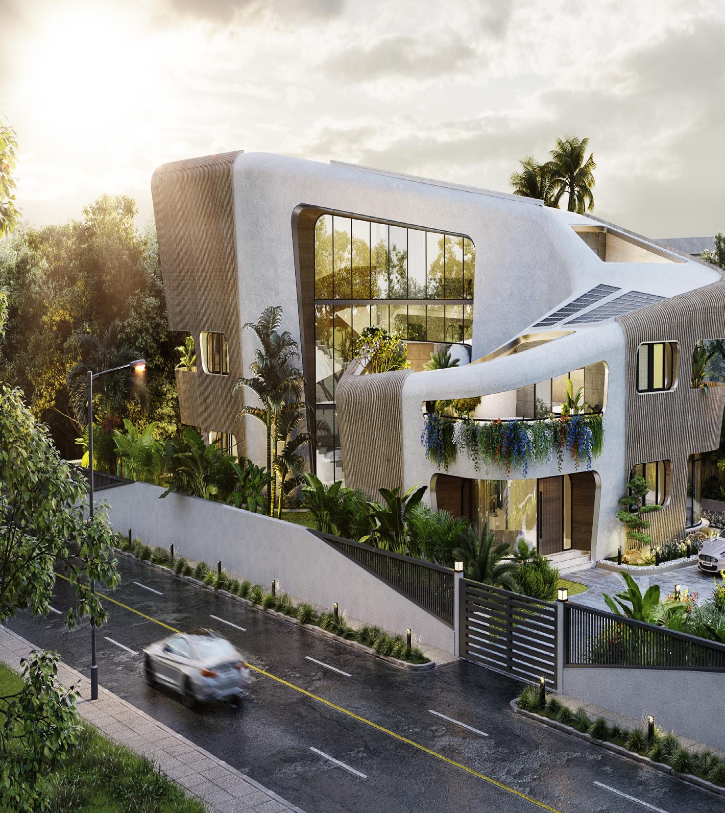
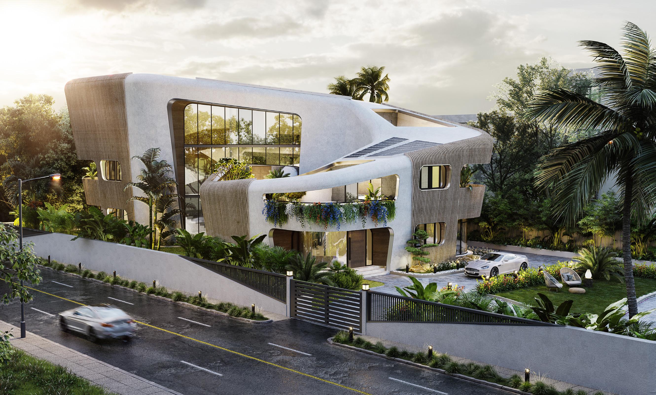
A MODERN ARCHITECTURAL RESIDENCE
WHERE FORM FOLLOWS FUNCTION
ARCHITECT : JEGANATH JB ARCHITECTS
AREA : 340 SQM
YEAR : 2021
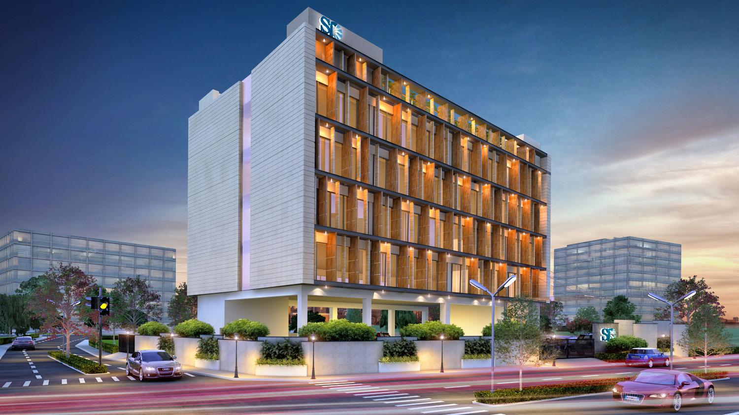
1. S & D IT OFFICE (OMR, CHENNAI)
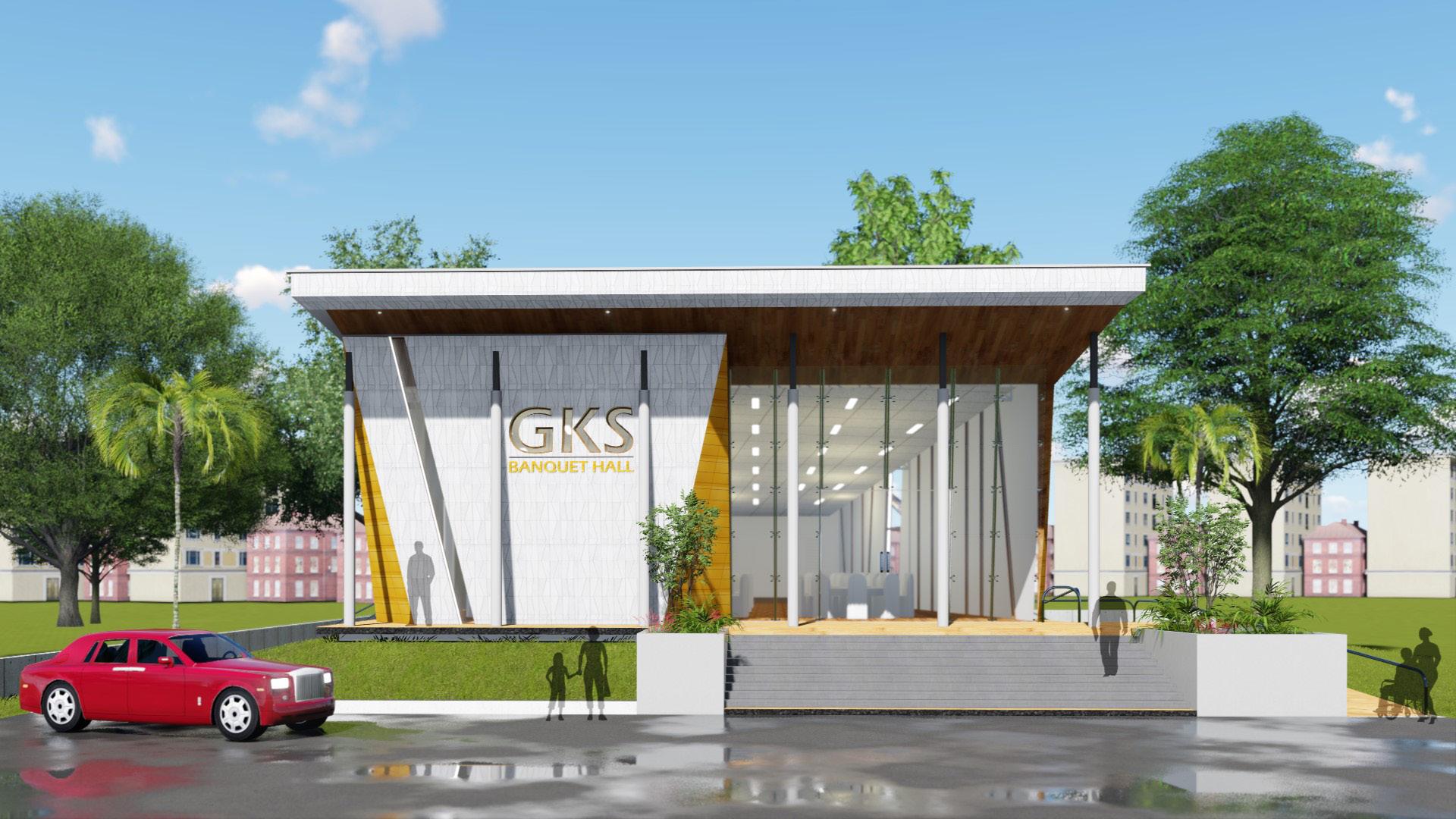
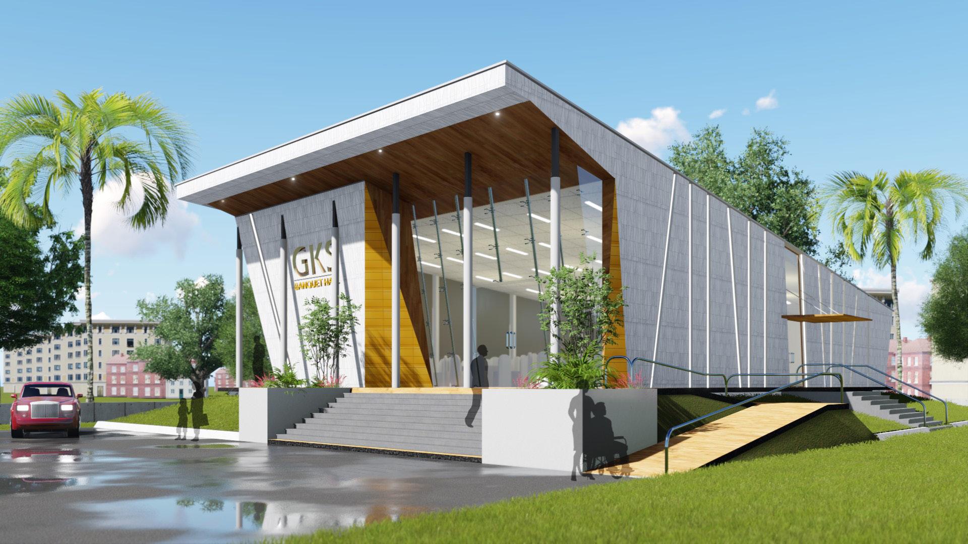
2. BANQUET HALL (TANJORE, TAMILNADU)
3. THIRU.
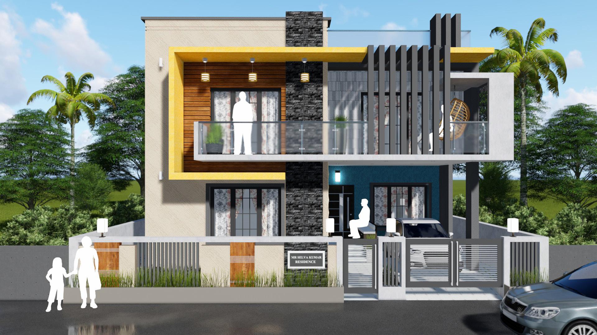
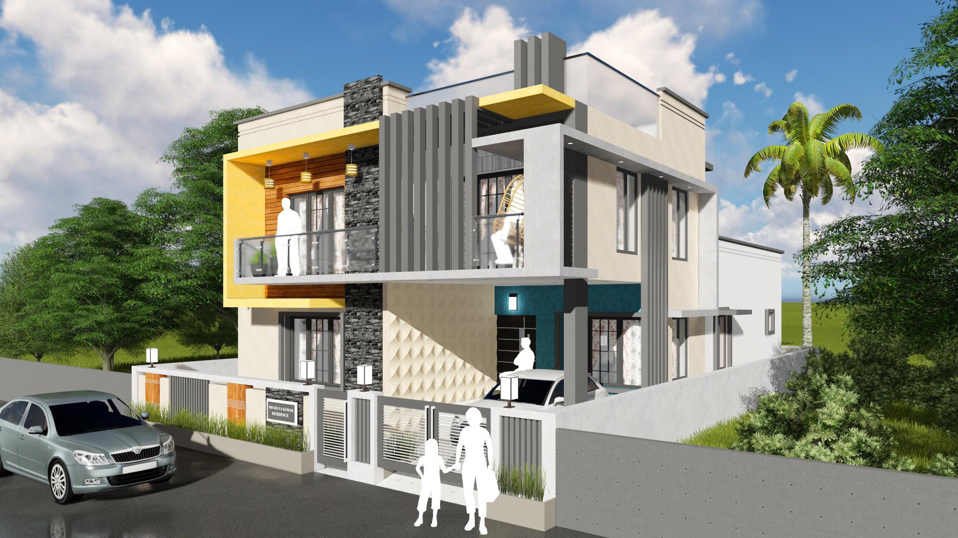
4. MR SELVAUMAR RESIDENCE - FREELANCING (THIRUVARUR, TAMILNADU)
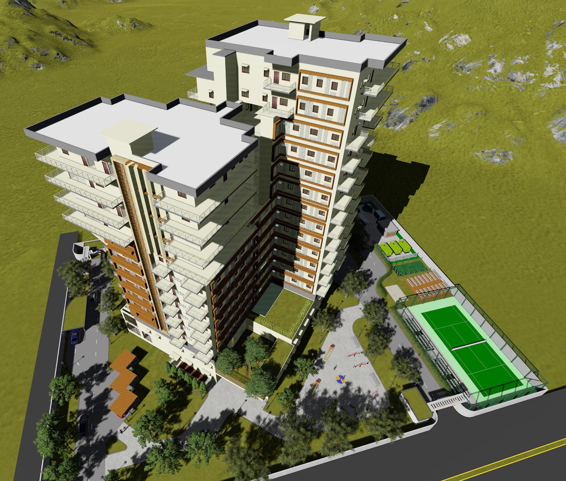
5. LUXURY APARTMENT (ACADEMIC PROJECT)
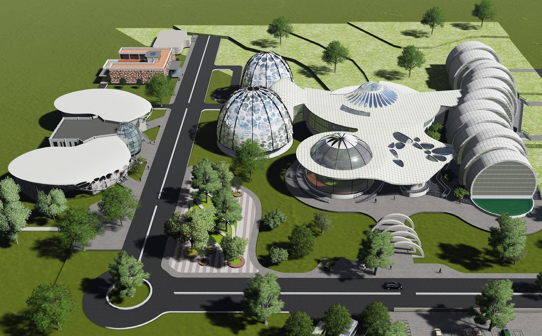
6. SERICULTURE MUSEUM (ACADEMIC PROJECT)
Contents Portfolio
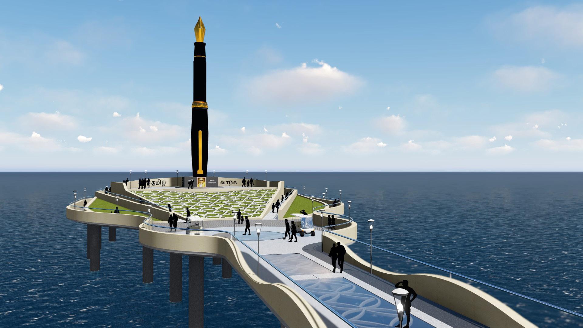
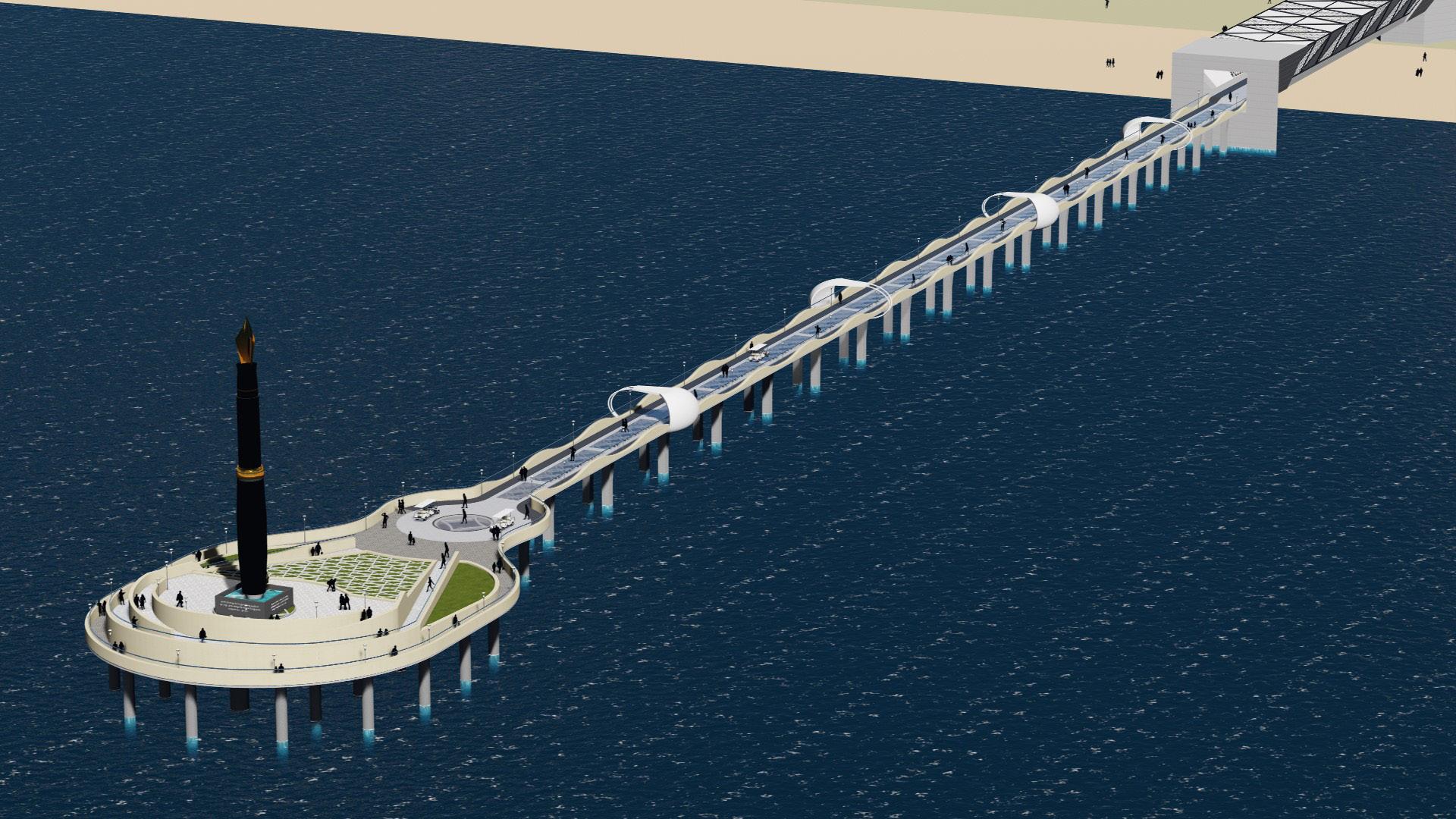
KALAIGNAR ARUNANIDHI MEMORIAL (MARINA BEACH, CHENNAI, TAMILNADU)


01ZCRS (ZERO CARBON LIVING)


PROJECT DESCRIPTION
Architect : Midori Architects
Designer : Ar Bharathi Shanmuganathan
Area : 715 Sqm
Year : 2020
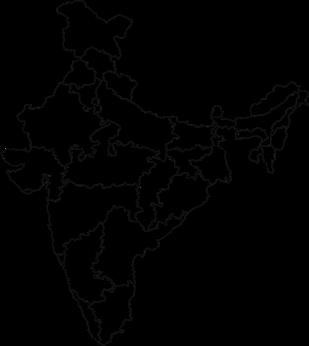
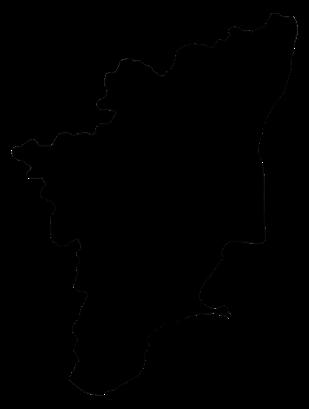
Location : Santhome, Tamilnadu, India
Status : Under Construction
DESIGN OVERVIEW :
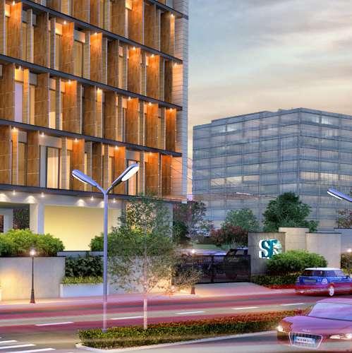
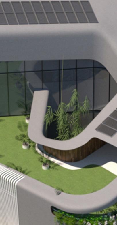
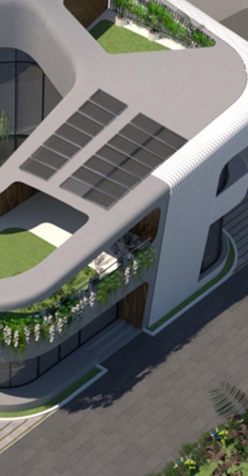
This unique and modern home is a perfect example of modern meets sustainability and functionality. Designed as a response to environmental parameters, this home is all set to earn the first of its kind Zero Carbon & LEED Platinum Certification and provide luxurious comfort with energy efficiency
With corridors that snake around the courtyards connecting the private spaces and rooms with double height glass walls, this home emulates subtle elegance and smart design
Courtyards, curves and inclinations on the form are strategically designed to incorporate self-shade, sunlight and ventilation which give way to modern aesthetics enhanced by a wooden exterior.
CERTIFICATIONS :
1.

2. PUBLICATIONS :

AIMING TO BE THE INDIA’S FIRST ZERO CARBON HOME
PURSUING
LEED V4.1 RESIDENTIAL CERTIFICATION
Ful Article (BUSINESS TODAY) - https://reader.Magzter.com/pre view/yjn8sb2nu3fd0zgkuq33xt67597416674642/675974#page/1
Hardcopy available on stands (June 27th 2021)


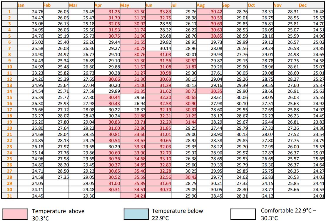
CLIMATE ANALYSIS REPORT


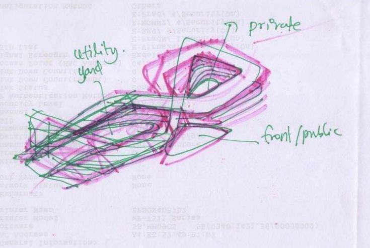
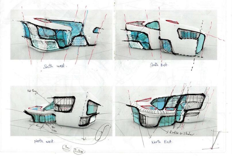

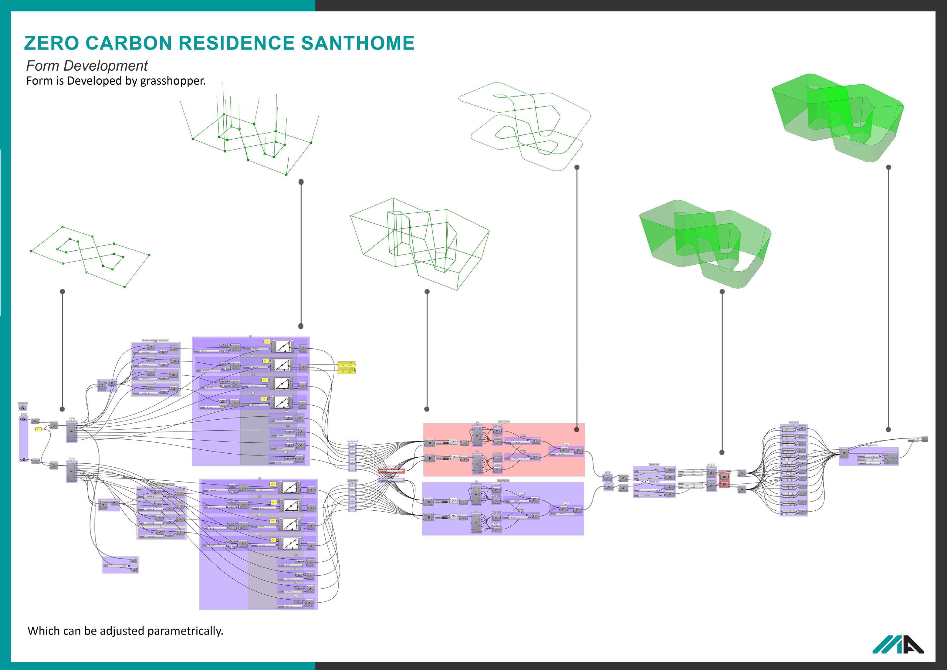
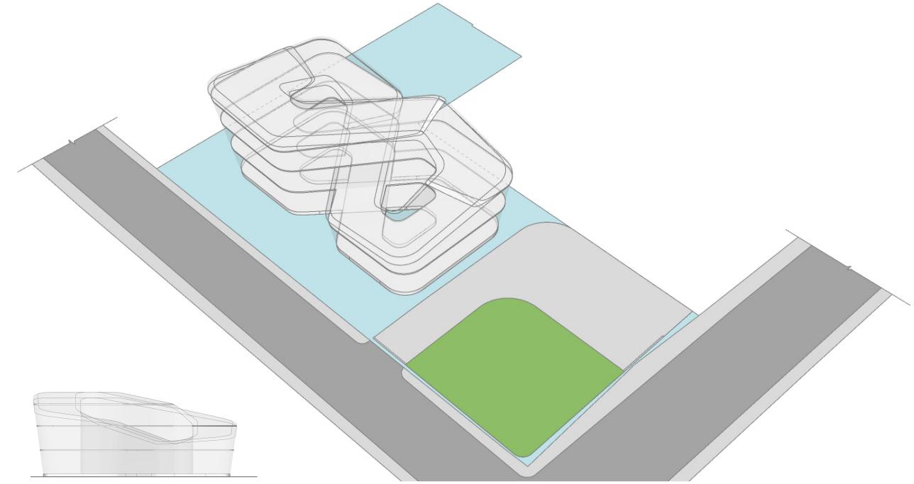
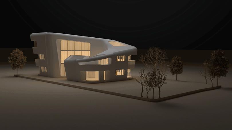
The project starts with sketching and constant effort on understanding the requirements of the project and evolving a meaningful design concept that provides solutions to the requirements and paves ways to built a sustainable home with LEED Platinum Certification. AEON House means “Life” translated as “for eternity” and the concept incorporates the infinity symbol fashioned in the shape of Mobius Loop. As the “Infinity” concept was developing, we incorporated the energy efficient design principles like Natural Lighting, Shading & Ventilation. The question remained - how could all these aspects be incorporated into a technically feasible structure without taking an eternity to build?
To overcome this technical difficulty, Parametric design approch was taken with Rhino & Grasshopper - providing, detailed sections & measurement drawings explaining each and every aspects of Mobius Loop form for the building contractors to understand the design and to manufacture the site specific formworks.
Daily Mean Temperature Throughout The Year:
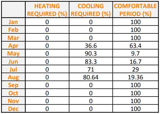
Cooling Requirements :
Precipitation :
Inference :
Based on the daily temperature data table, it is evident that no heating is required at allthroughout the year.
The cooling is required for the peak summer months from April to August.
May is found to be the month which needs highest percentage of cooling load i.e. 90.3% as the temperature is found to be maximum throughout the month.
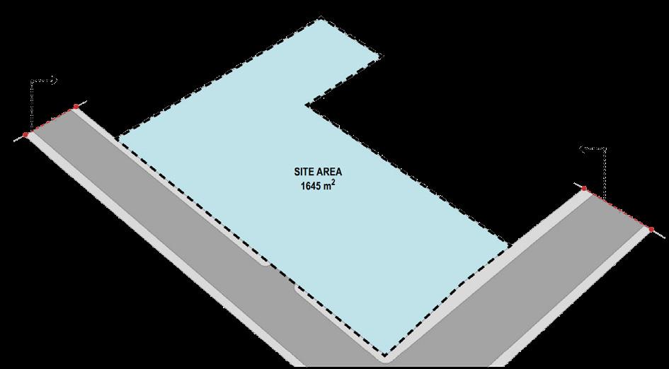
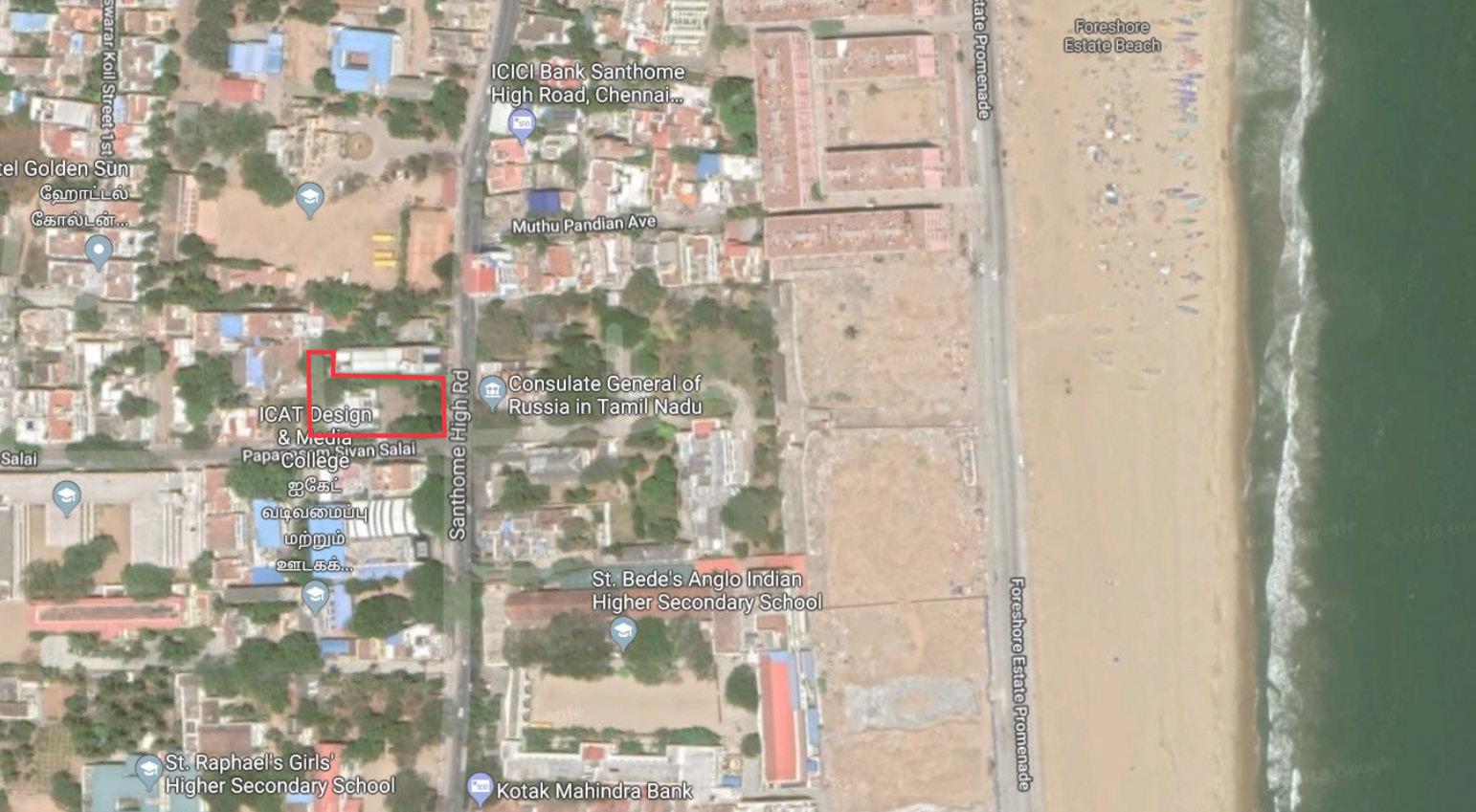
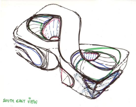
The site is a L - Shaped plot facing towards east direction with the overall area of 1645sqm & located on santhome, Chennai. Upon various options for the site, this particular (1645sqm) site was analyzed and strategically selected for this project due to the following advantages.
Site location (Center of chennai), Ease of Access (To other locations through road), Ease of Access and proximity to the Public Transportation Maximum availability of Local Vegetations for improved local climate.
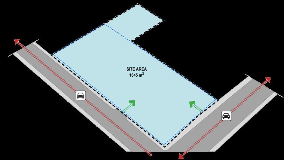
A 11.73m wide Santhome High Road acts as a major road which provides access to the site on eastern side of the plot. Even though the site has abutting roads on both east and south diretions, East side (Santhome High Road) road was selected as a major road and site facing direction for vastu compliance. As per vastu square / rectangular plot with perpendicular corners was recommended for residential construction. As per vastu consultant’s suggestions, Imaginary rectangle of maximum size that fits inside the plot is only considered for developing the building, The remaining area of the vastu plot is used for auxiliary additional requirements.
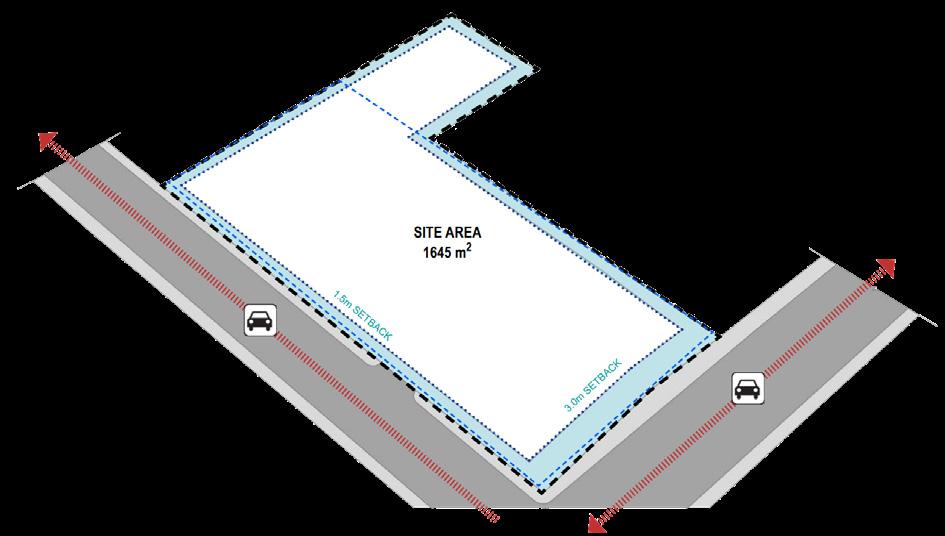
As per the local building byelaws (TNCDBR), Front setback - 3m Side setback - 1.5m (on each sides) and the Rear setback - 1.5m
These minimum setbacks to be left as the open space without any architectural or structural projections around the plot boundary and any built structures inside the proposed site.
On north west corner of the plot, Auxiliary buildings were proposed as a ground floor structure. Minimum setback rule were also applicable to the same.
Inference :
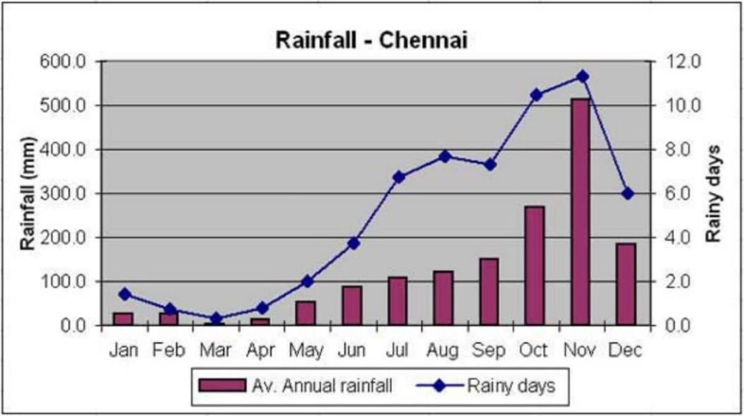
Precipitation starts during the mid of summer period with an average rainfall of 3.6mm.
The average rainfall gradually increases till September & A drastic increase is observed in the month of October and November with an average rainfall of 268mm and 512.5mm respectively.
Average Rainfall (mm) & Rainy Days per month :
Inference :
The highest rainfall is recorded in the month of November with about 512.5mm and the lowest rainfall is recorded in the month of March with about 3.6mm.
The average annual rainfall is found to be 1550mm, which could be utilized in a better way by implementing strategies in the design such as rainwater harvesting system, storm water management systems, etc.
SITE ANALYSIS & DESIGN DEVELOPMENT:
Site & Road Connectivity : Site Location : Conceptual Sketches : Project Fact Sheet : Vastu Line & Site Access :
Minimum Setbacks : 1.5MSETBACK 1.5MSETBACK 3MSETBACK 1.5MSETBACK 9.42m Wide Abutting Road 11.73m Wide Abutting Road Santhome
Papanasam Sivan Road
High Road
:
INDIA TAMILNADU CHENNAI PROPOSED SITE SANTHOME MARINA BEACH
1. 3. 4. 2.
1 2 3
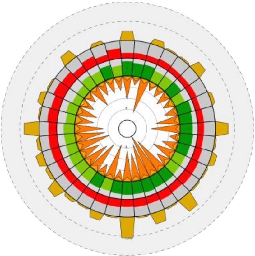
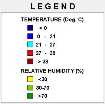
From the annual wind wheel diagram, high wind speed of 8 m/s is observed in the southeast direction but the total number of hours the wind prevails in the mentioned direction is found to be very less, i.e. nearly 2%. Average wind speed of 4 to 6 m/s is observed in the directions of west, south west, south east and east. The wind from the southern direction prevails for nearly about 12% of the total hours and the wind from west, south west and south east direction prevails for about 5 to 8% of the total hours. The rest of the direction has minimum wind speed and it lasts for a very less period of time.
The relative humidity is observed to be high (above 70%) in the south and south-east direction whereas it is found to be within the range of 30 to 70% in west and south west direction. The temperature range is also maintained between 24 to 38°C. Therefore, from the inferred data, we can conclude that windows could be positioned on south and south west but along with a proper design consideration of shading devices.
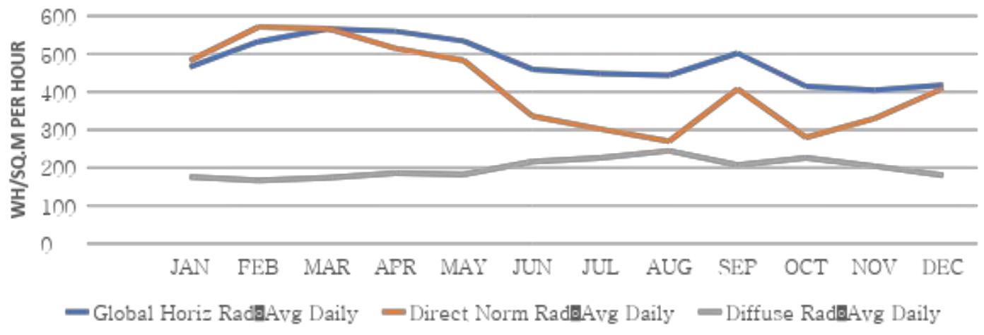
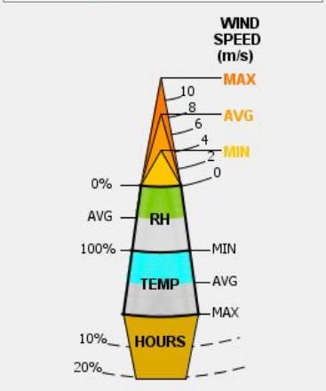
The maximum Global Horizontal Radiation (Average Daily) was observed during Pre-Monsoon period of tamilnadu, Which falls under March to May. This duration also coincides with the Summer Season which records maximum average temperature throughout the year. The Monsoon period of tamilnadu (Between June to December) receives the minimum average global horizontal radiation.
The september, where the change of monsoon occurs receives nominal Global Horizontal Radiation. During Rainy & Winter seasons (November to Feb) Starts with the lowest recorded Direct Normal Radiation and gradually increases and attains its peak limit during summer season.
Conclusion :
The above mentioned study shows that the Direct Solar Radiation range was comparatively in line with the corresponding seasons Therefore corresponding design measures to be taken to reduce the incident solar radiation levels of the proposed buildng.
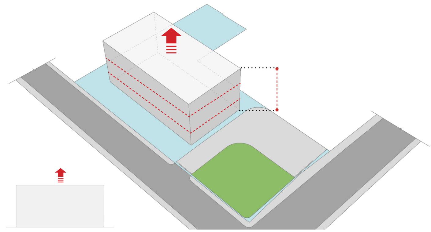
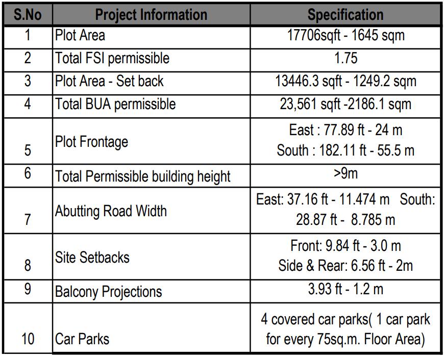
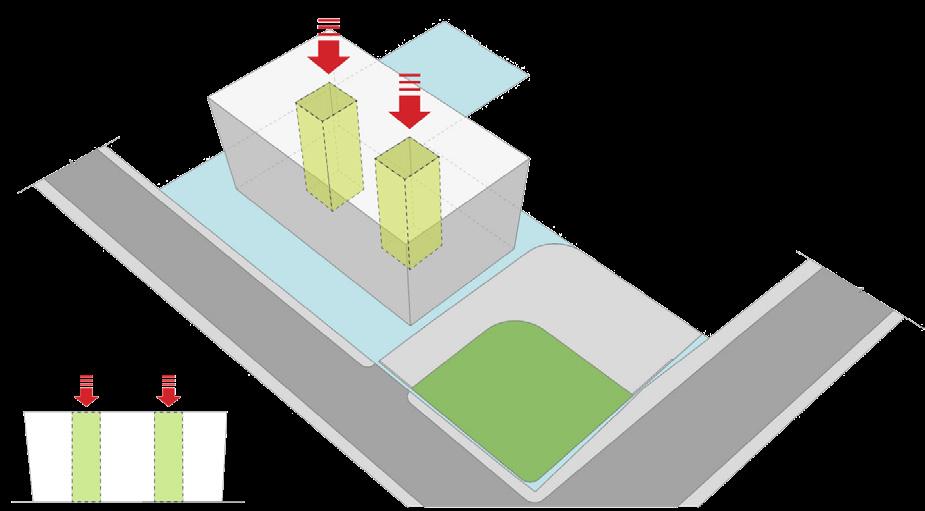
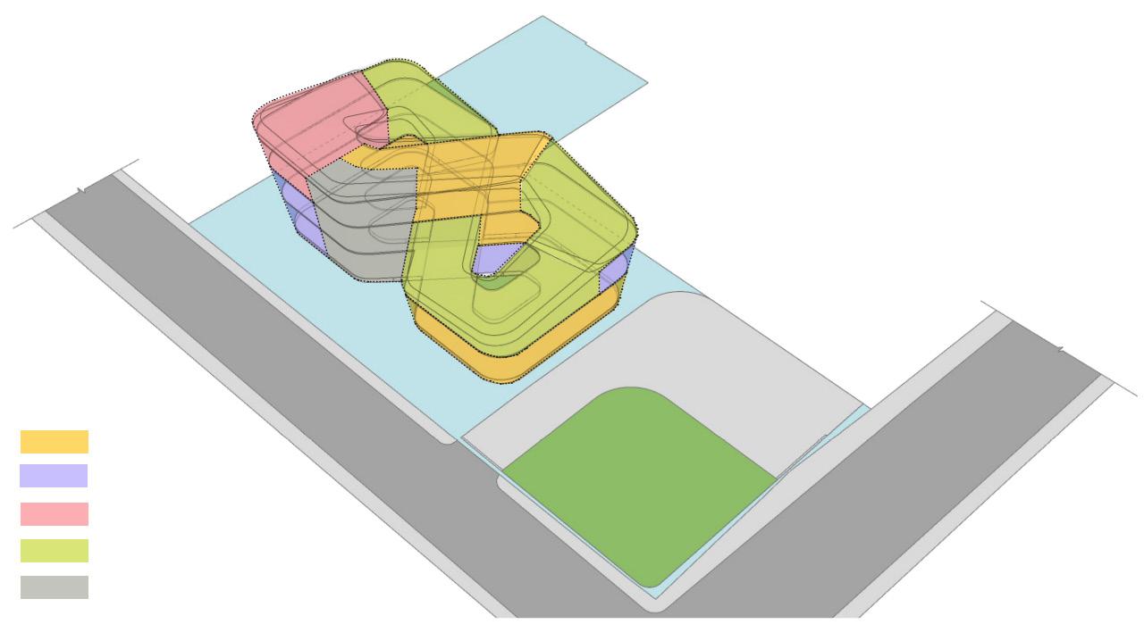
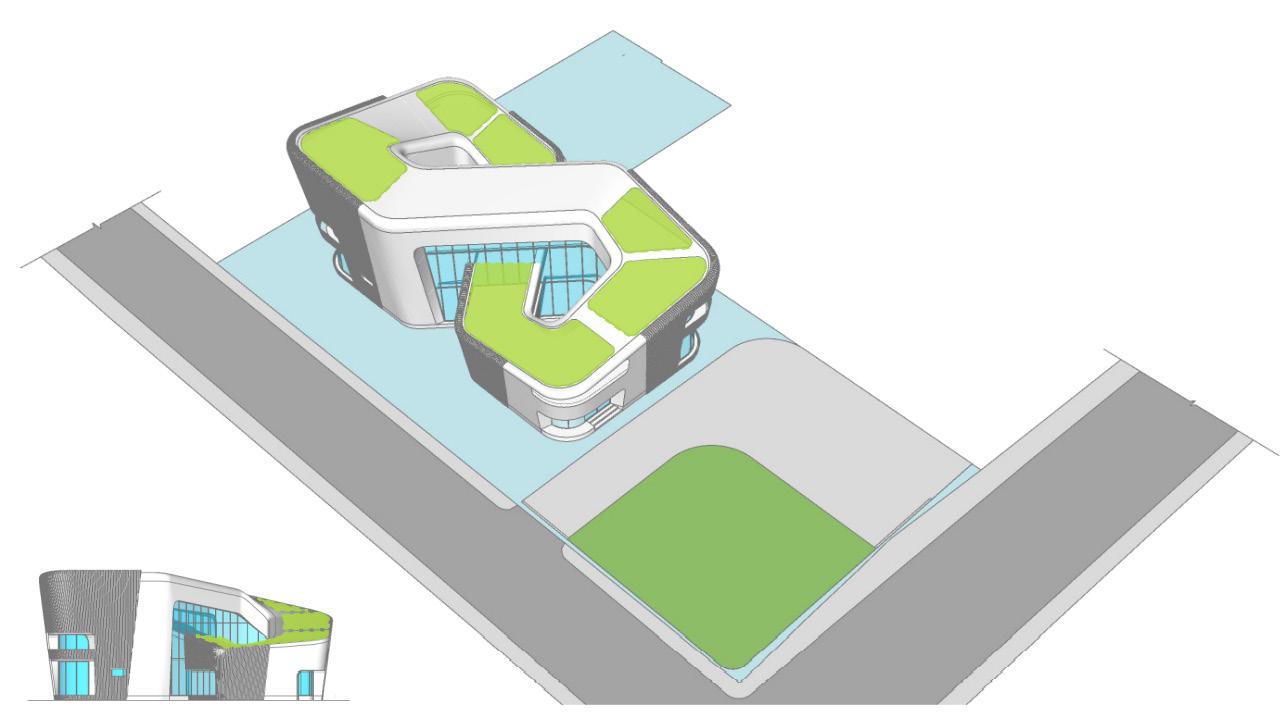
The building profile was strategically calculated and oriented - facing to North - South direction so that to avoid the longer side of the building facing East - West Direction (Reducing the Harsh Incident Solar Radiation). The building profile was extruded to 12.5m to accomodate the (G+2) structure.
To further enhance the utilisation of natural daylighting and airflow into the building, two semi enclosed courtyard was introduced on the north and south facade of the building as shown on the form development representations.
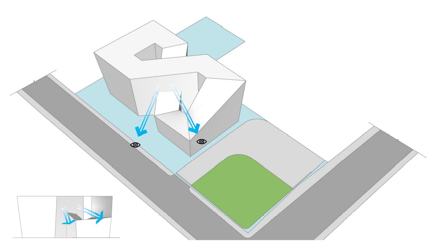
A form pushdown is strategically designed to avail the direct views of the horizon and landscape on site entrance from the first floor terrace & living area on the second floor.
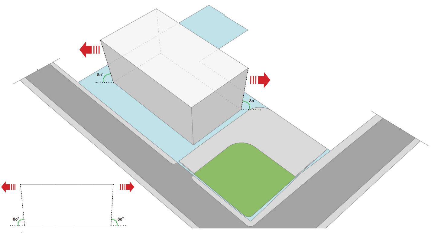
The Exterior walls are inclined outwards at an angle of 10deg Which inturn acts as a form which self shade itself and prevents the building from harsh incident solar radiation. This strategically developed form helps in reducing the heat gain into the building and the energy consumpsion of the building.
(Designed for LEED Net Zero - Certification)
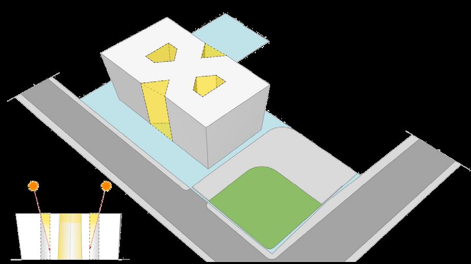
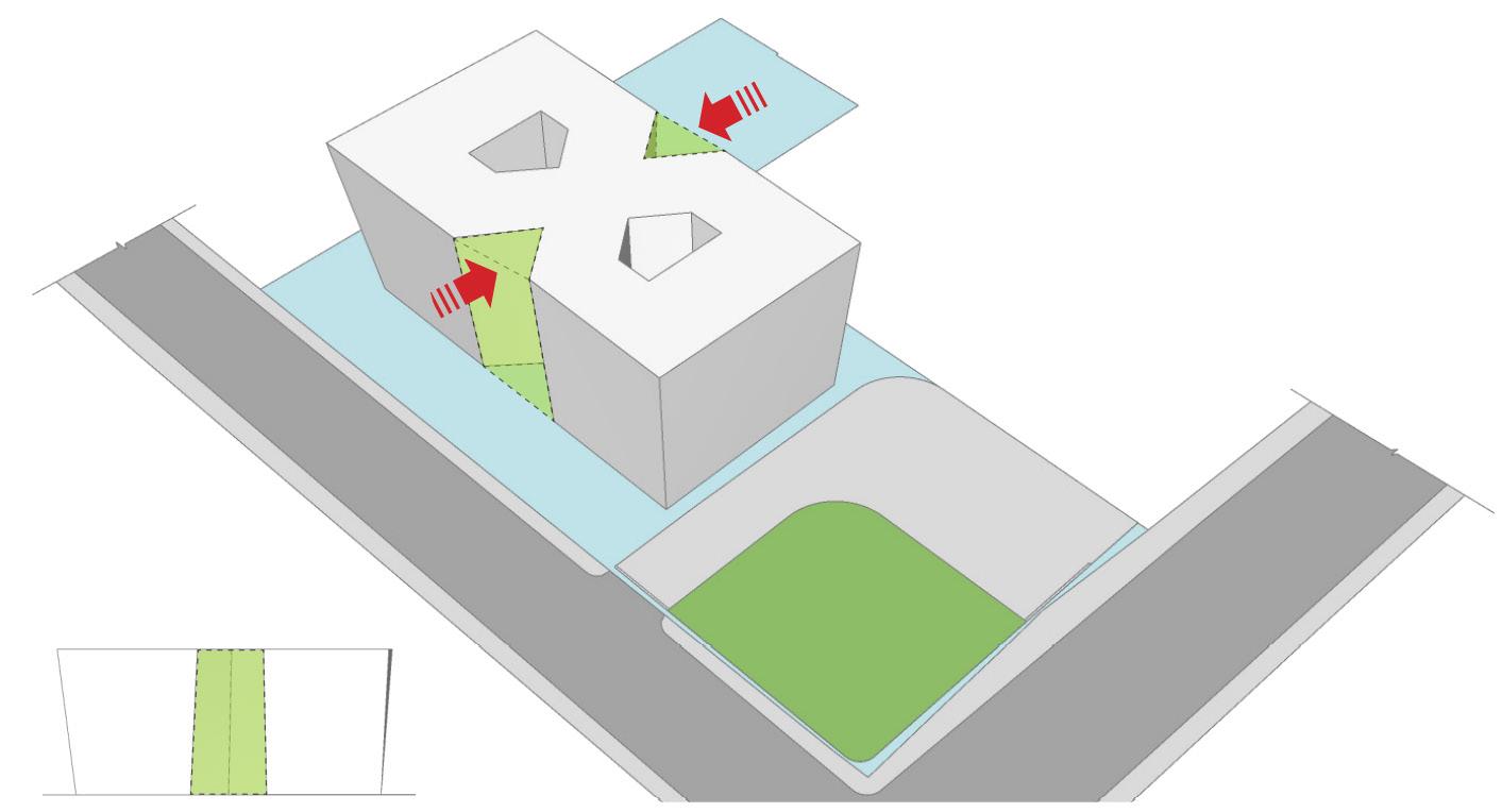
The fenestrations present on the inner faces are shaded by the tubular shape of the courtyard and receives the diffused light throughout the day. The semi enclosed courtyard enables the interior spaces to receives adequate daylighting.
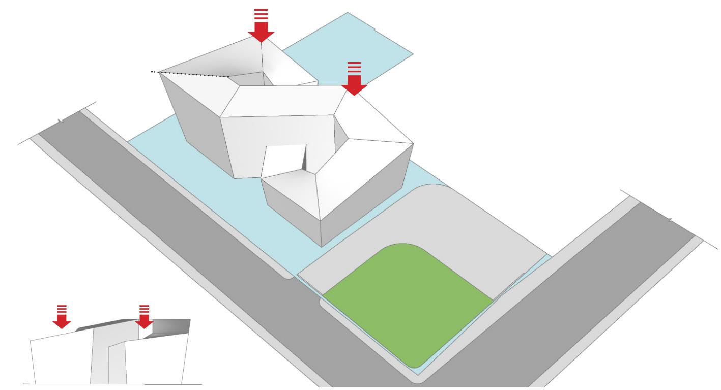
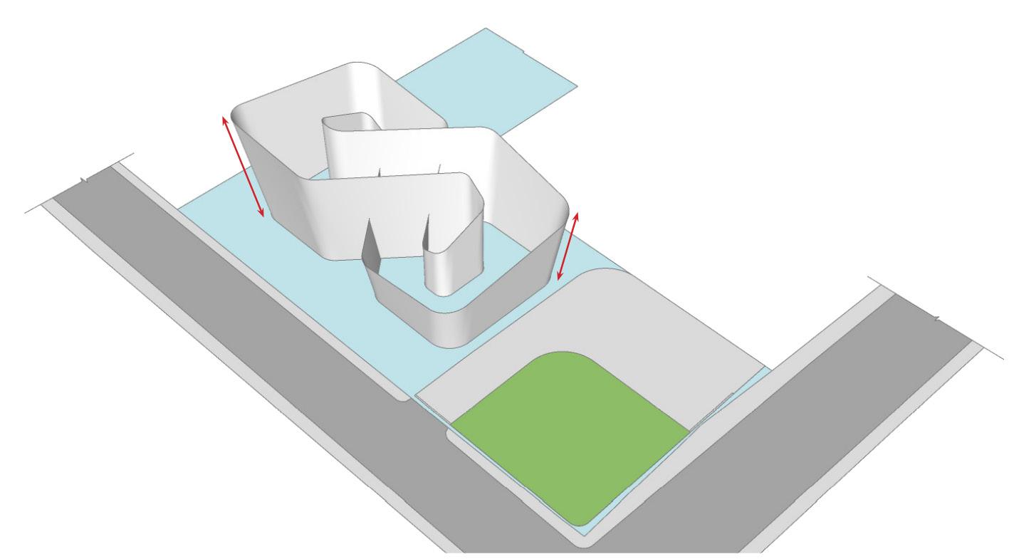
As per the Vastu consultants recommendation, North west portion of the building needs to be the highest portion of the building.
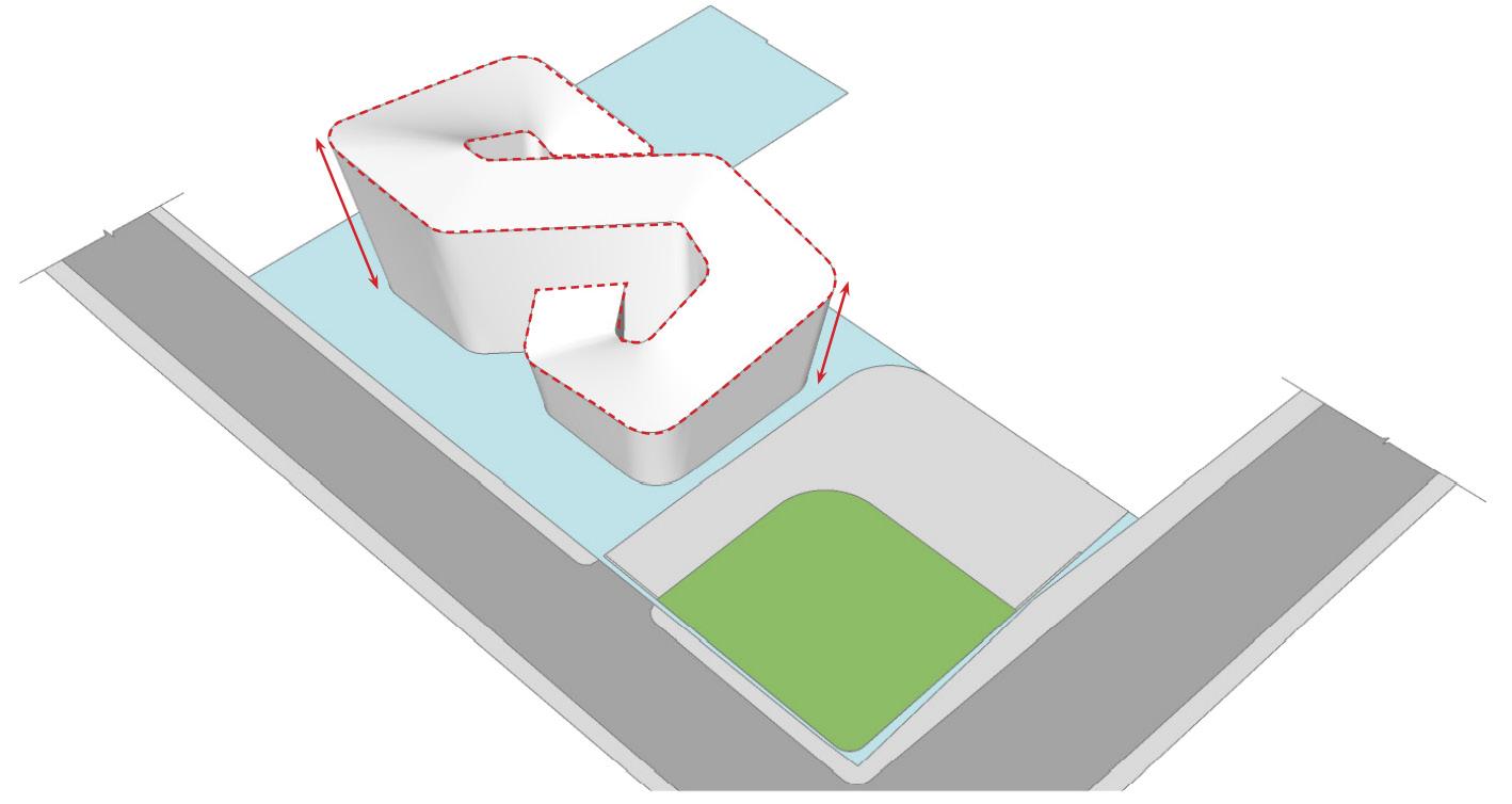
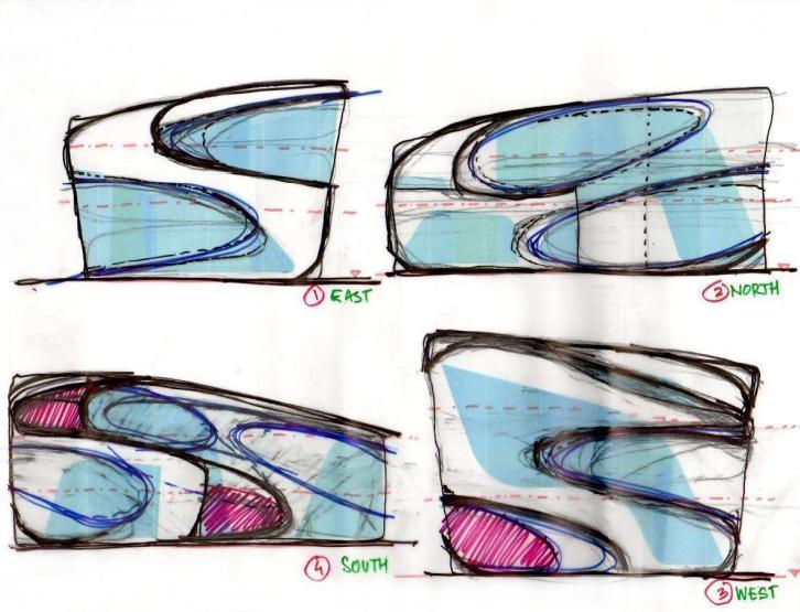
Using Loft and Sweep technique, the roof for the developed form was created by connecting the inner and outer curves of the top (Roof) loop.
To enhance the utilisation of natural daylighting and airflow into the building, two enclosed courtyards was introduced on center of the building as shown on the form development representations. This enables the daylight to reach the inner portions of the residence and also creates cross ventilation throughout the building spaces.
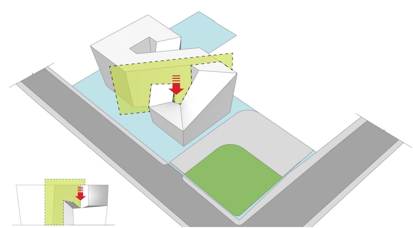
A imaginary plane was created and considered as a slicing plane, the southeast portion of the developed building form is pushed down as shown in the representation.
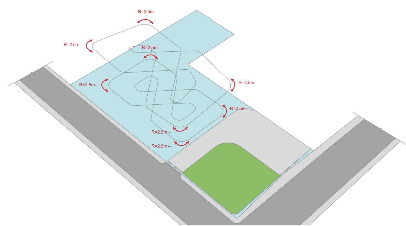
The form of this futuristic home is essentially a “Mobius Loop’’ To develop this form further, Careful computational design approach was put forth to explore the shape grammar and infinite possibilities using “Grasshopper’s Generative Scripts”.
Using the wireframe method, the top (Roof) and bottom (Floor) loop of the developed Mobius Loop form was accumulated. The external corners of the Top & Bottom loop was filled at the the radius of 2.5m.
This enables the building to perform well aero-dynamically and the curved profile provides welcoming aura to the building facade.
To respond to the abstract notions of function, aesthetics, performance and project requirements, Generative scripts were used to explore the shape grammar and infinite possibilities.
DESIGN DEVELOPMENT:
The filleted Top & Bottom loops were lofted to create the interior & exterior walls of the building while maintaining the pre calculated 10deg outward inclination of the developed form.
Extruded Block
Scaled Block : Closed Courtyard : Semi Enclosed Courtyard : Light Well : Slicing Plane & Form Pushdown 1 : Views Out :
2 : Wireframe & Filleted loop : Lofted Surface (Walls) : Loft And Sweep (Roof) :
REPORT :
:
Form Pushdown
CLIMATE ANALYSIS
Annual Wind Rose Diagram :
Monthly Radiation (WH/SQ.M per hour) : Inference Inference
N S 20% 10% E W
12.5m (G+2) 4 7 10 13 5 8 11 14 6 9 12

1. Open Space
The landscape was developed to provide greencover using native species. The total site area is 1645sqm while the total landscape area is 696 sqm.

6. Renewable Energy
The structure generates surplus renewable power.

2. Rainwater Management
From the rooftop and terrace area, 100 percent runoff is collected in an underground sump.

7. Lighting
Double glazed windows with VLT (Visible light transmission) of 0.51, SHGC (Solar heat gain coefficient) of 0.28 were used for glazing. This ensure optimum light in the house.
Vertical lines with desired length were created and 10deg outside slope were strategically added to individual coners of the base loop.

3. Heat Island Reduction
The reflective - white paint used on rooftops is 90 per cent. Similar methods have reduced the area that contributes to the heat island effect by 79.75 per cent.

8. Heat Gain
Due to the inclination of the exterior walls (80 degrees), the building shade itself.

4. Double Roof
Extruded polystyrene insulation is used to reduce the heat transfer on the roof.

9. Thermal Comfort
The physiological comfort is optimised by ensuring adequate cross-ventillation. The comfort zone established is 21-24 degree celsius.

5. Water Use Reduction
Water saving techniques such as drip irrigation wrere used. Indoor water fixtures have low flow rates that reduce water usage by 41 per cent.

10. Local Food Production
Of the total landscape area of 696 sqm, around 263sqm (38 per cent) has been used for food production.

Overview :
If you believe that transport, manufacturing and energy generation are the biggest sources of carbon emissions, think again. Buildings and construction together accounts for 36 per cent of global final energy use and 39 per cent of energy related carbon dioxide emissions according to the International Energy Agency’s Global status report 2017 prepared for the Global Alliance for Building and Construction. While rising awarness about the climate change and its impact on lives and livelihoods is encouraging more and more people and companies to build sustainable, netzero energy and zero carbon buildings, the trend, say experts, is not catching on fast enough to make a meaningful difference.
“The concept of net zero carbon (Buildings) is at a very nascent stage but certainly gaining importance at the corporate level. Housing projects may take some time to chase netzero carbon status”, says S.Karthikeyan, Principal Councellor, CII Indian Green Building Council. Eventhough building a zero carbon house is not an easy task, considering all the harsh impacts this creates on the environment, we decided to evolve the design to obtain Leed Zero Carbon Certification.

Challenges :
There are no guidelines for designing a zero carbon home in india. However, the Indian Green Building Council (IGBC) published a pilot version of the “Net Zero Energy” rating system in november 2018 which can act as a guide while designing a zero carbon home. “Carbon is different from energy. Carbon covers the bigger picture, including materials with which the building is constructed, “says Sunita Purushottam, Head of Sustainability at Mahindra Lifespace Developers Ltd.
Some of the major challenges are awarness about what netzero carbon means and availability of supporting service providers, Low carbon products, Materials and Technologies, apart from use of renewable energy in buildings. Moreover, a zero carbon home does not merely mean an energy - efficient building with neutral or negative emissions.
The process starts from the planning stage itself and covers the choice of site (so that there is enough sunlight and wind to generate renewable energy) and construction material to use of renewable energy, apart from efficient waste and water management.

Our Approach :
Site / Orientation :
The top and bottom loop were isolated and the individual corners were filleted to the radius of 2.5m.
Using the upper ends of extruded lines, two top curves forming the upper loop was created.
The Loft technique was used to create a continuous plane (Exterior Wall) which connects the articulated top and bottom loop.
The loft and sweep technique was used on the two curves on the top loop to create the roof surface over the structure.
As the house will use electricity generated by renewable sources, The site location was choosen so that it reveives ample light, heat and air. The longer side of the buiding is oriented towards North and South direction to avoid harsh radiations from the East and West directions. The pasive cooling techniques were also strategically incorporated into the design development process.
Construction :
According to IGBC, the external walls should be built using six-inch fly ash bricks, with plaster on both sides. In addition to the fly ash bricks, Green cement (Manufactured using a Carbon - negative process) and heat reflective paints to be considered. Besides, Greencover should be added wherever possible.
Rapidly renewable materials such as bamboo, eucalyptus, bagasse and certified wood were proposed for the furnitures, fixtures and external vertical fins to reduce the embodied carbon from material procurement.
Clean Energy, Energy - Efficient Appliances :
The rooftop solar panels were proposed so that the house should be able to produce as much or more, electricity than it consumes. Our vision is to run the building entirely on renewable energy throughout the building lifetime. Large windows were strategically designed and proposed so that the building receives ample lighting and to avoid artificial lighting needs during the day time.
To reduce the energy consumpion, BEE - Certified appliances, LED Light fixtures which consumes less energy were proposed. Sensor - based lighting solutions were used to turn off lights automatically if there is nobody inside the rooms.
Recycle & Reuse Waste Water :
An on-site water teratment system and separate plumbing lines are proposed to reuse the treated waste water for flushing and other requirements, which ensuresoptimum use of water. Roof top & Site runoff rainwater were also harvested.
Waste Management & EV - Charging Points :
To prevent the waste from being sent to landfills, On - site waste segregation strategy was implemented. Separate bins to collect the Dry & Wet waste was proposed for recycling process. To eleminate carbon emission due to vehicles, Usage of electronic vehicles with charge station provision on parking garrage was proposed. GENERATIVE
THE AEON HOUSE, A ZERO CARBON HOME :
IMPLEMENTED DESIGN STRATEGIES :
Inner and outer curves for the base loop is loaded into the grasshopper.
GRASSHOPPER
SCRIPT FROM

Building Block
Exterior & Interior Courtyard
Inference :
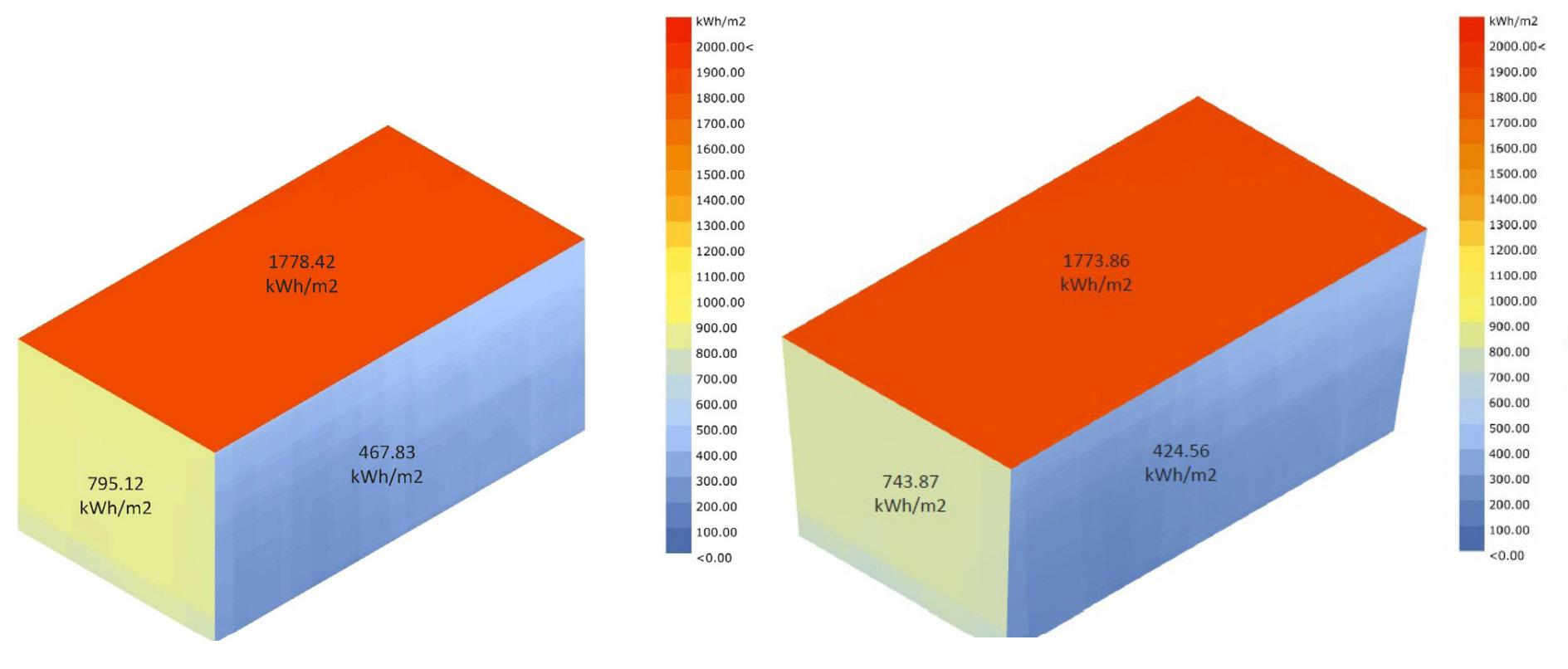
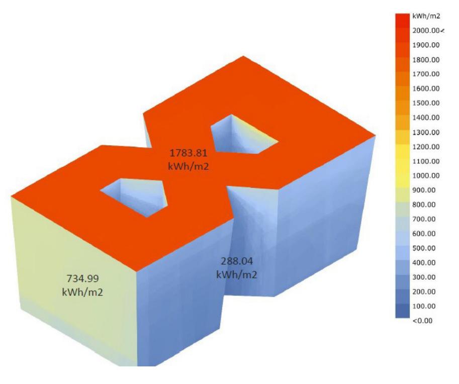
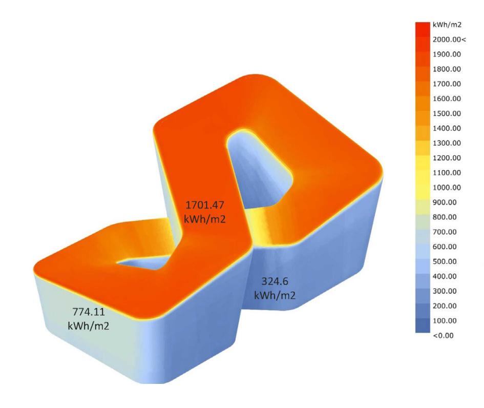
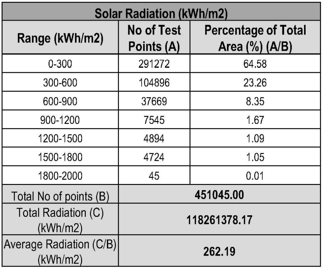
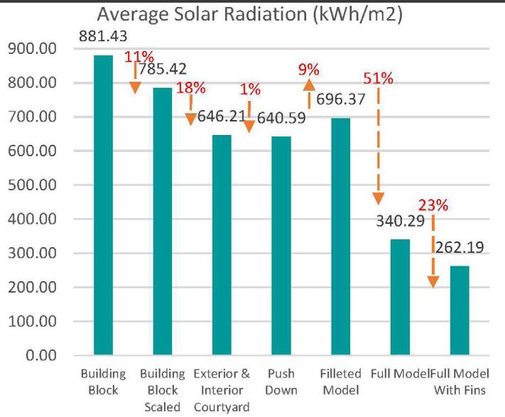
The buillding performance optimization is an integral part of the design development process. Each step shown in the design development process is carried out after performing carefull Analysis, Simulation and Confirmation of the design, satisfying and meeting up with the desired results towards sustainability & efficiency.
The average solar radiation data chart shows that the performance of the building gradually increases as the design development process evolves.
Filleted Roof
15
Building With Floor Plates
Zoning
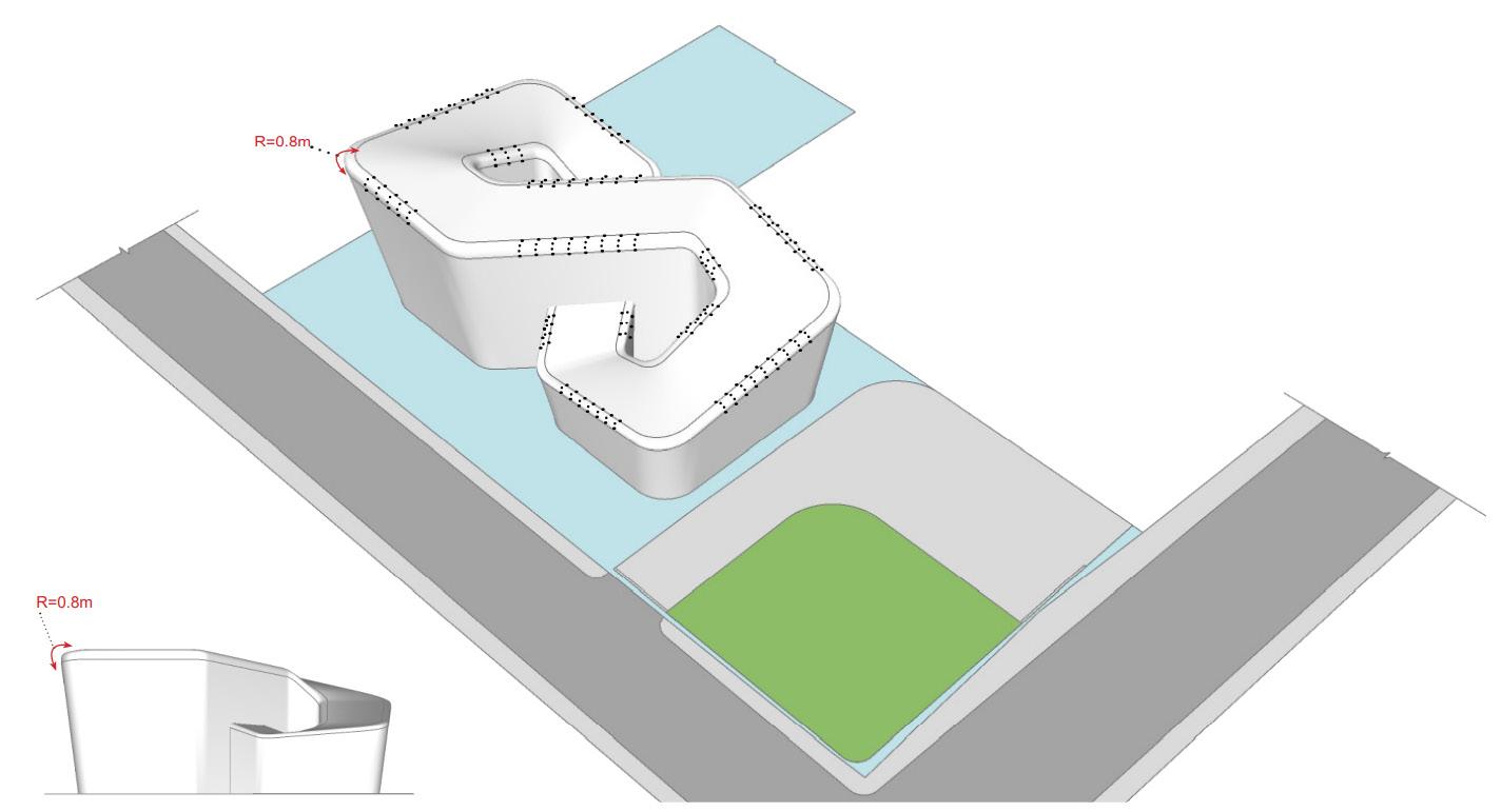
The edge where the roof & wall intersect was filleted by 0.8m radius, this enables the building to perform well aerodynamically and the curved profile provides welcoming aura to the building facade.
External Vertical Stripes :
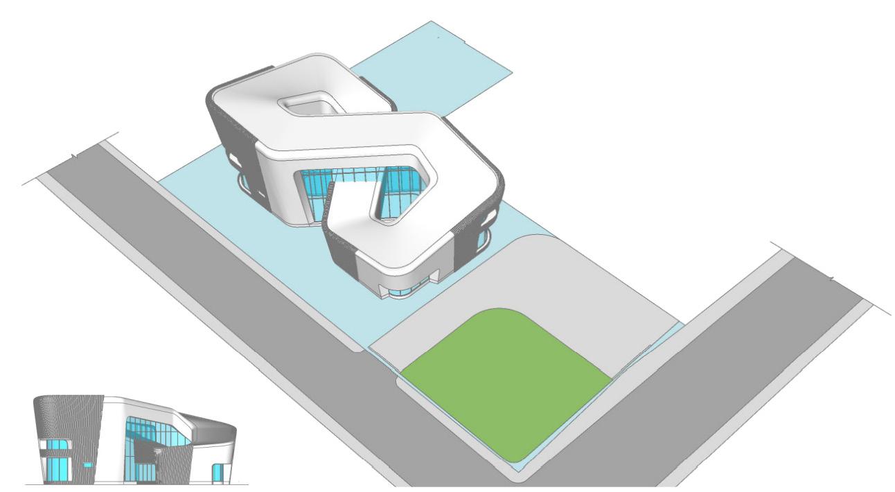
To further reduce the heat gain into the building, External vertical wooden stripes were introduced to prevent the harsh incident solar radiations. This design element is strategically provided to reduce the energy required for building performance and to attain the Net Zero Cetification.
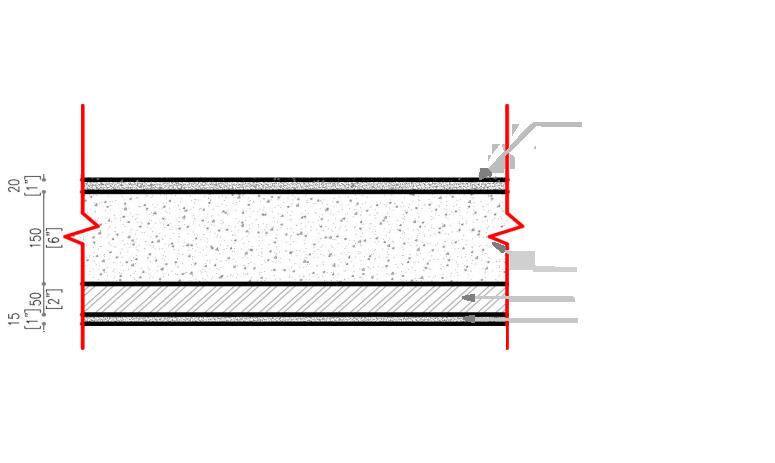
TYPICAL DETAILS :
16 19
The building floor plate of 0.15m thick was introduced at the clear distance of 4.0m from the formed ground level.
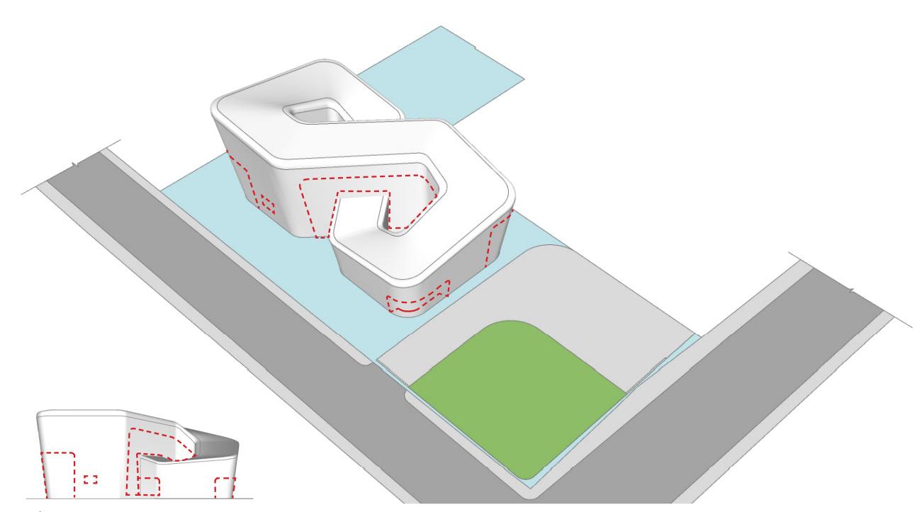
Recessed Walls
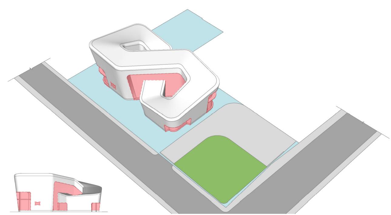
The walls were recessed inside where as the form itself is inclined outwards at 10deg slope. This further prevents the building from harsh solar radiations where the resession act as a shading device to the curved windows. This design articulation is precalculated to reduce the solar gain into the interior spaces and paves the way to the reduction in energy for building performance and Net Zero Certifications.
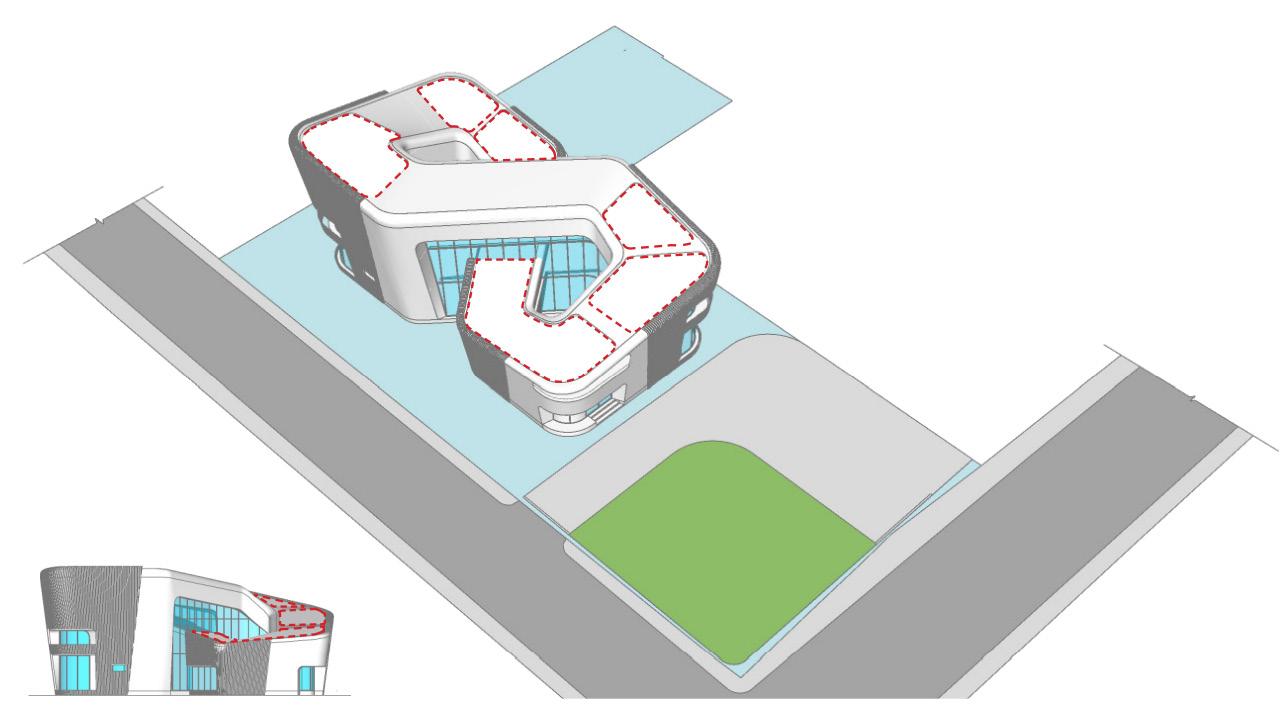
The cutouts were introduced on the roof which flows throughout the developed form. The precalculated location of cutouts provides openings for terrace garden on first and second floor and terrace, which accomodates the service area.
Windows :
The bedrooms were placed on the corners of the Mobius Loop which enables the habitans to avail the views to the outside landscape through the convex window.

17 Convex windows were designed and inserted on the all corners of the building which provides seamless view to the nearby landscapings. Aluminium supported structural glazing (Double Glazing) were provied on the north and south facing wall.
The terrace garden and landscapping were designed and located in such a way that, the views to the outside through the structural glazing & convex windows will always have the greenery and vegetations. This enhances the feel that the building is well connected to the nature. Roof Cutout
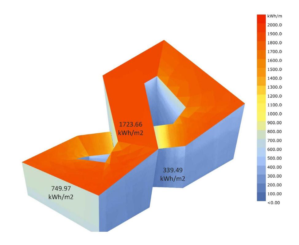
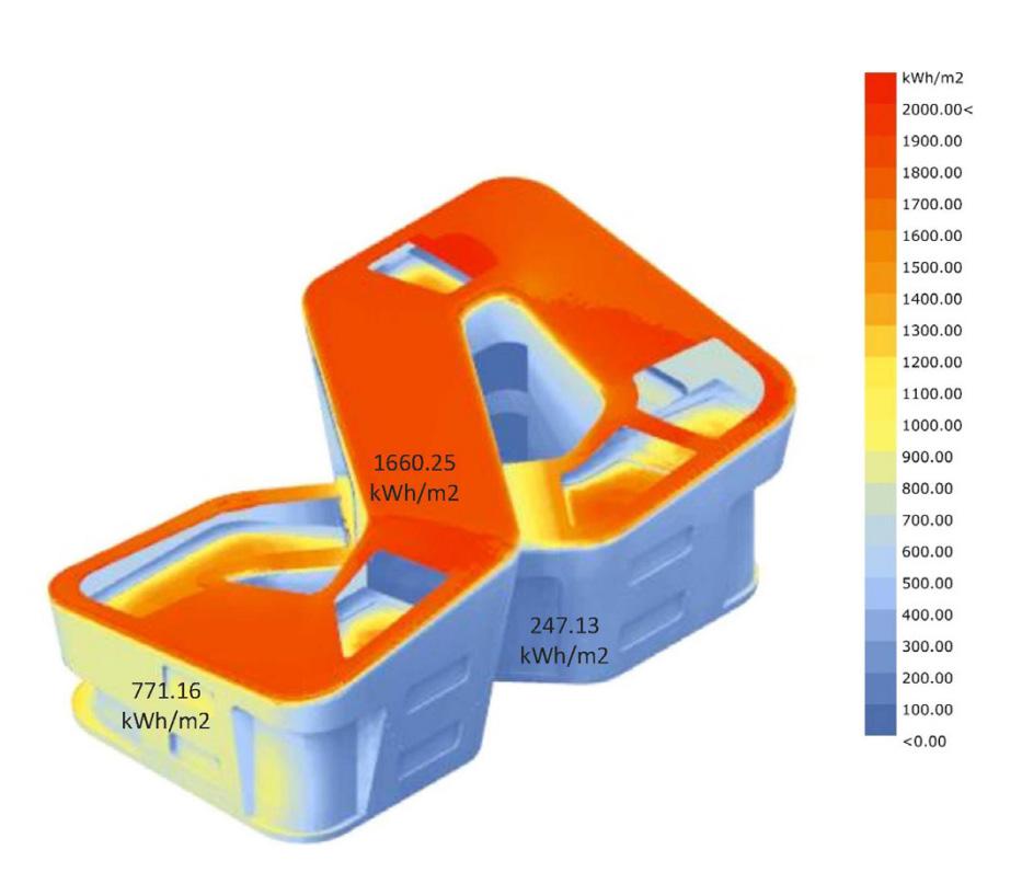
DESIGN DEVELOPMENT: RADIATION ANALYSIS AND REPORT :
:
:
Corridor & Living Area LEGEND Bedrooms Home Theatre Landscapes Service Core
:
:
: Terrace
&
: 18 21 20 23 22
Garden
Vegetations
Filleted Block : Building Block Scaled : Push Down Full Model With Fins :
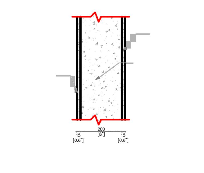
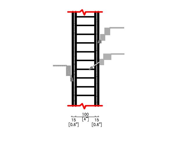
External Wall : Internal Wall : Roof With Landscaping : Internal Plaster Internal Plaster Finishing Outside Outside Outside Inside Inside Inside Concrete Slab Internal Insulation Internal Plaster Aerocon Block RCC External Plaster External Plaster
FENESTRATIONS
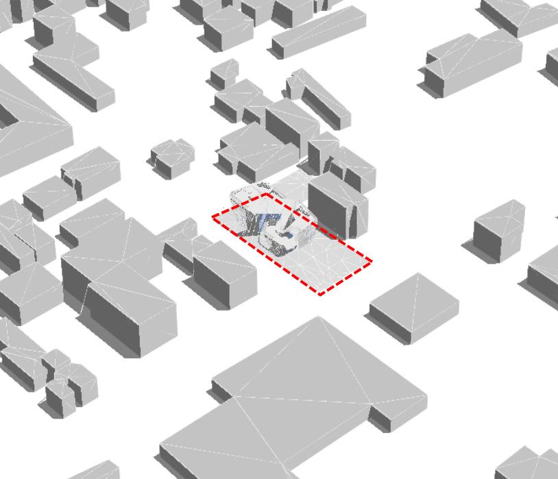
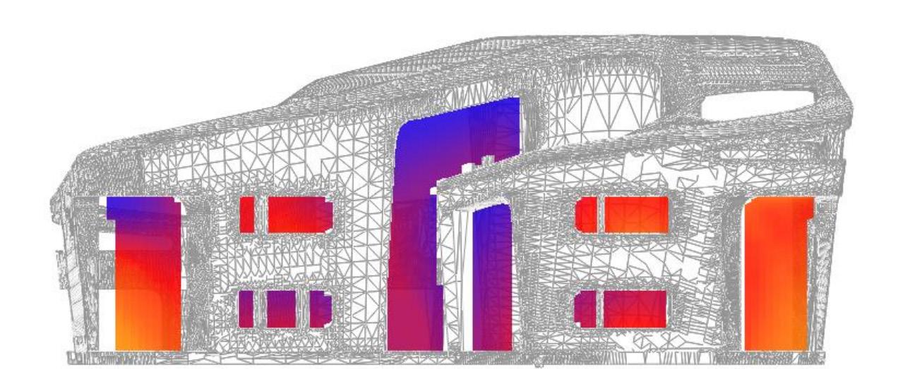
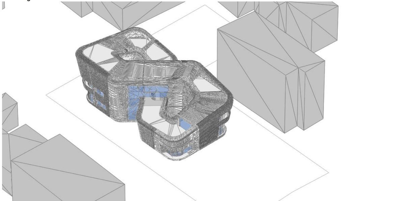
The buildings around the site were also considered in radiation analysis for accurate results.
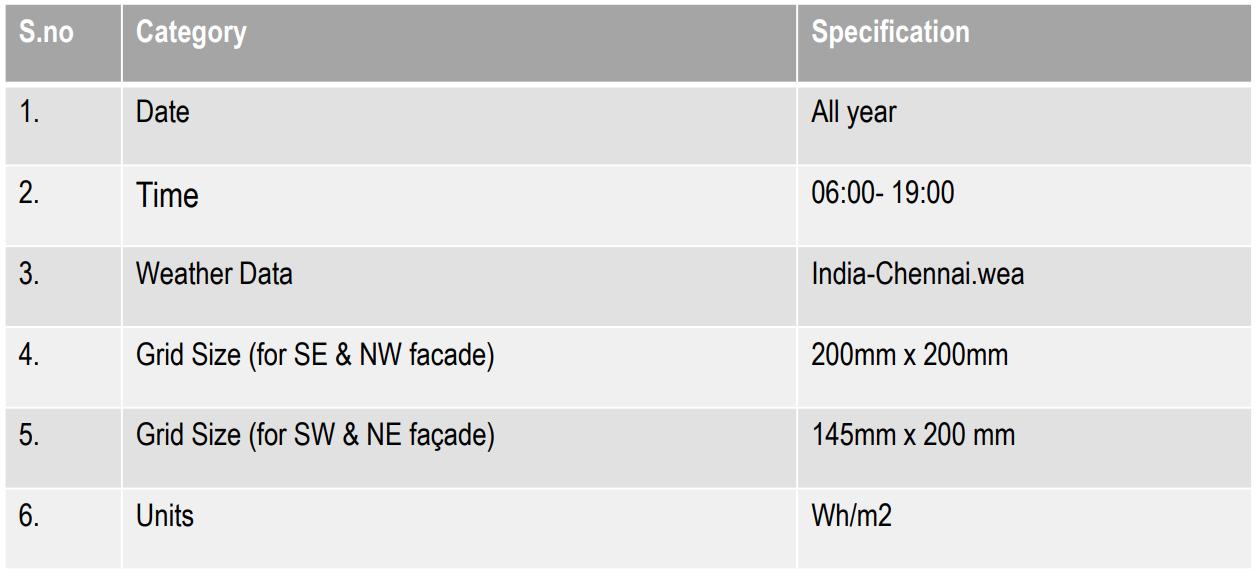
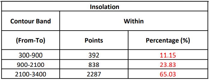
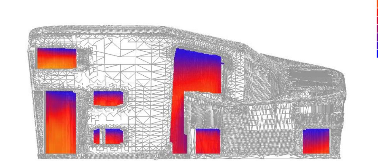
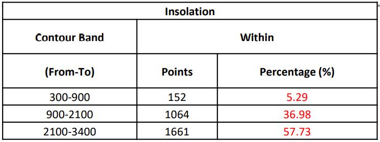
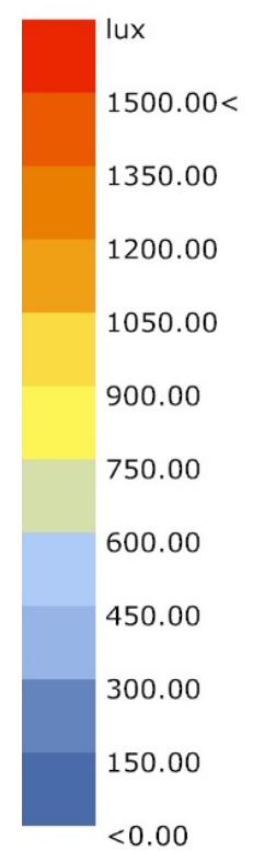
The solar radiation analysis for the fenestration were carried for an year, a grid size of 200mm x 200mm was choosen for the simulation results. The simulation was performed for an entire day (Sun rise to Sun set) to obtain more accurate results.
The units for the results shown is wh/0.04 sqm for North west and South east facade. To get more accurate results latest weater file for the site location was used for the solar radiation simulation for fenestrations.
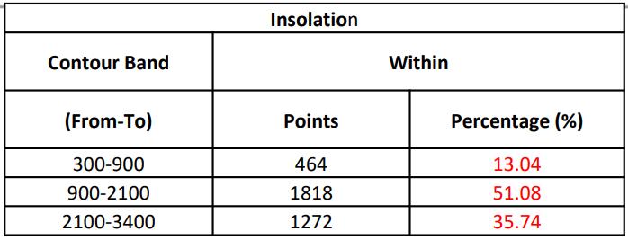
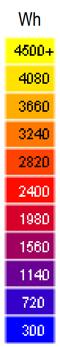


IRRADIATION or INSOLATION is the measure of Energy of the Solar Radiation in units Kwh/m2. It is the amount of solar radiation (Kw) on a specific area (m2) in a specific time (h).
Direct Solar Radiation on the walls results in conduction of heat through the materials (like brick, concrete etc) direct solar radiation on the windows result in instantly heating up the spaces with in. This causes thermal discomfort, sometimes visual discomfort and both leads to over usage of AC and lights all through the day.
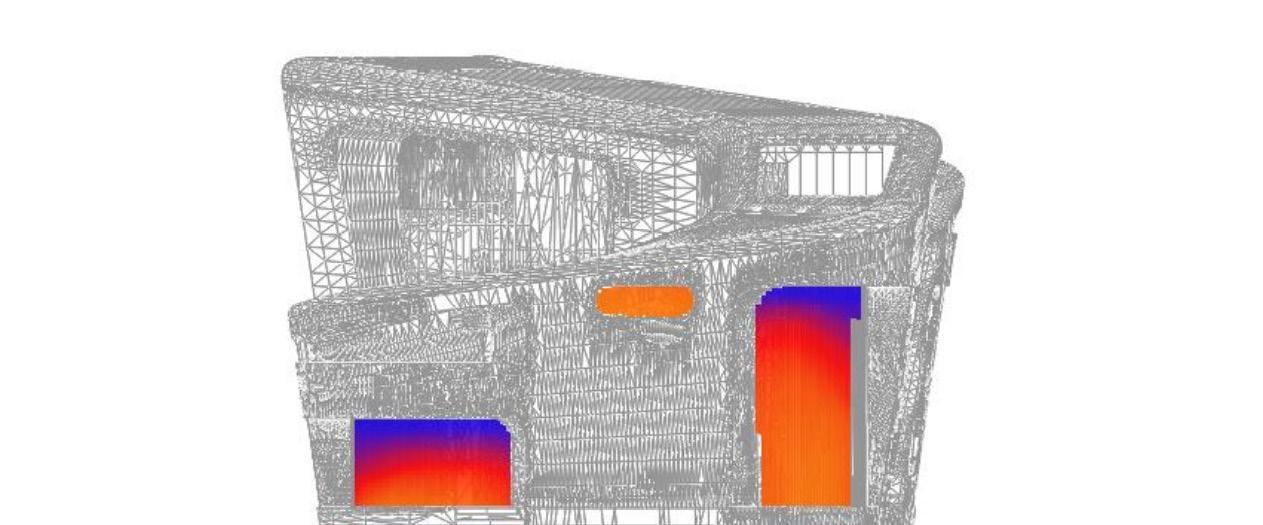
Here we observe that this Building is shaded only from the South West direction by the neighboring buildings and hence exposed to solar radiation from all sides.
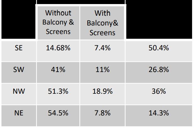
After the shading elements are introduced, there seems to be significant amount of reduction in the Solar Insolation, which will have a direct effect on the heat gained indoors.
Ground Floor - Sept 22, 9AM
First Floor - Sept 22, 9AM :
Second Floor - Sept 22, 9AM
In this project we have prevented admission of direct solar radiation on the walls and windows by
1. Twisting the floor plans to self shade each other.
2. Creating transitional spaces like terraces and lobby that can admit direct sunlight but allow only indirect sunlight indoors.
3. Adding perforated screens to filter in the solar radiation giving a good quality of light and radiation indoors.


Inference
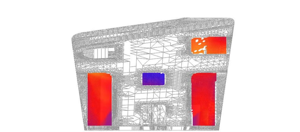
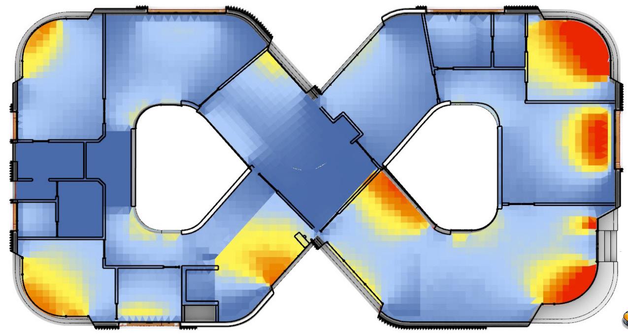
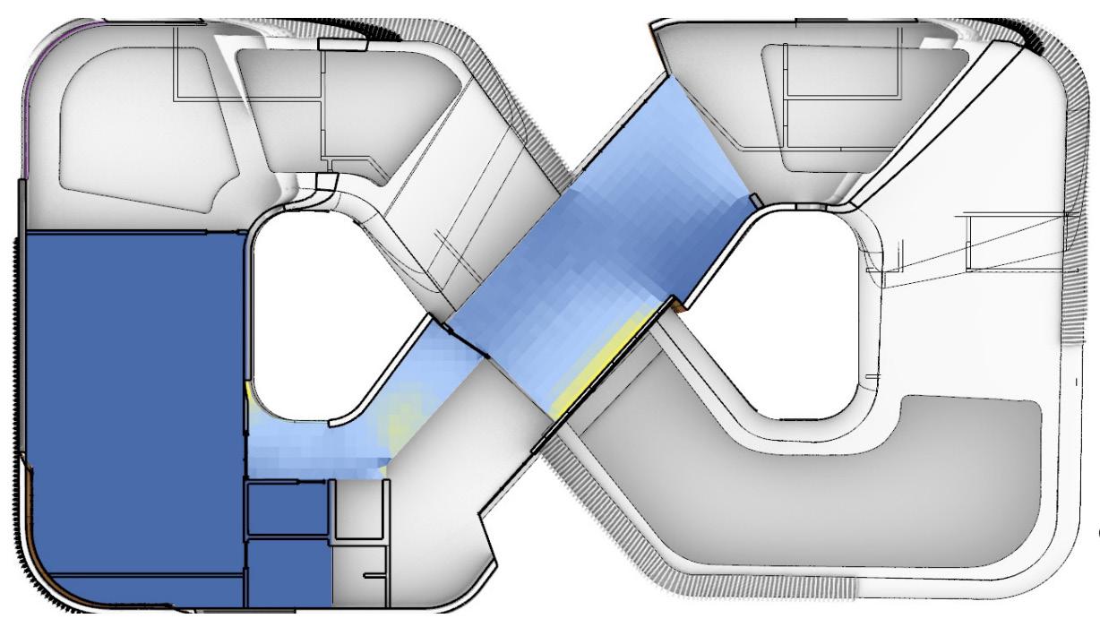
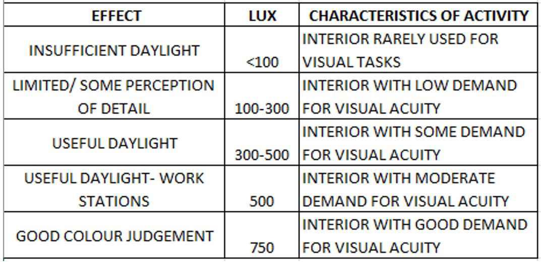
Following material reflectance value has been provided as inputs for the daylight simulation, 60% for walls, 50% for windows (VLT), 20% for flooring, 80% for ceiling. This simulation was performed for the date of 22nd sept (Equinox). It clearly shows that the eastern fenestration receives ample natural lighting into the habitable area due to the day time. The orientation of the building has given a right level of shading and exposure to sunlightby having only 2 regions that is lacking light and the regions being the transitional spaces, it is negotiable.
Balconies and Screens create the transitional spaces which receives maximum daylight and allows diffused light inside the spaces, reducing glare and over heating.
The theatre hall in the second floor receives zero natural lighting because absence of windows and to keep the space darker for better experience for the users (Artificially ventillated).
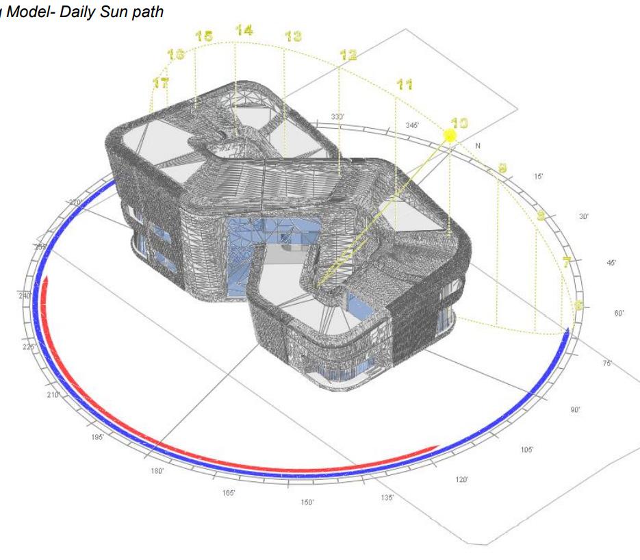
Proposed Site With Surrounding Buildings : Building Model - Daily
: Solar Insolation - North Facade : Inference : Solar Insolation - South Facade : Simulation Input Parameters : Solar Insolation - East Facade : Solar Insolation - West Facade :
(SOLAR RADIATION ANALYSIS) : DAYLIGHT SIMULATION :
Sun Path
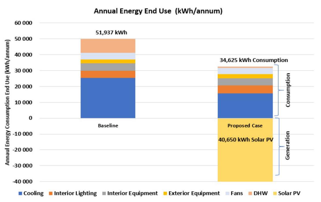


Carefull studies and analysis were carried out along with the Building Performance Consultants (BPC). Annual Energy Consumption (End Use) for a Baseline case building and Proposed building was analysed and constant efforts were taken along the design development process to minimise the energy consumption. As per the final study, 33.3 per cent of the energy consumption was reduced from the baseline building’s performance by implementing strategical design measures.
Our vision is to build a house which run’s entirely on the renewable energy which was generated from the site. Solar panels were installed on the rooftop to generate renewable energy during the day time.
Nearly 18 pre cent (6025 kwh) of enery is created more than that of the required energy using solar panels for the proposed building. This ensures the building not to rely on corporation’s local electric grid.
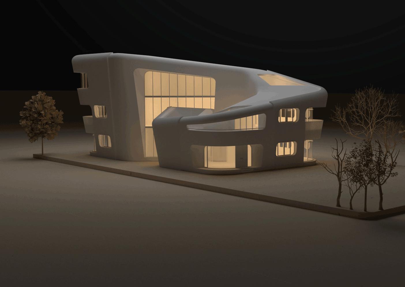
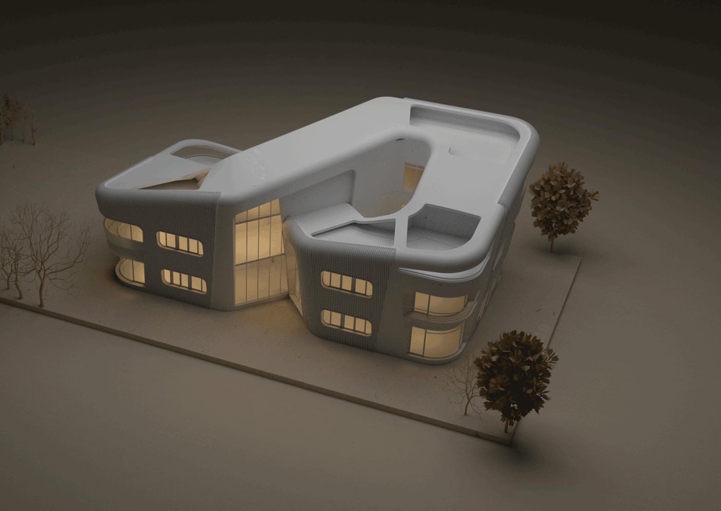
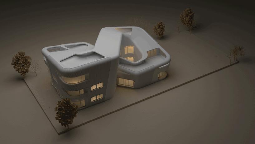
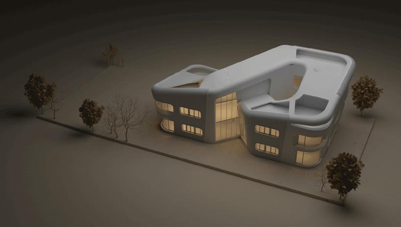
Conceptual Model (3D Printing) :
Inference : 1 2 3
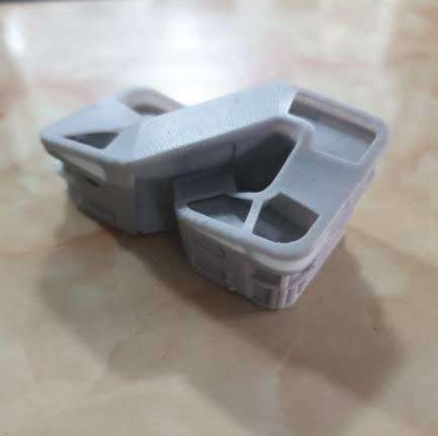
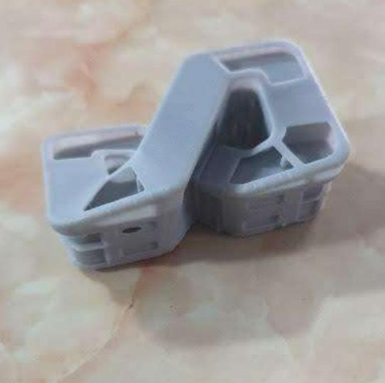
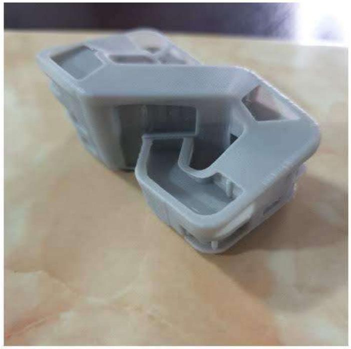
As an architect, we know that the physical model paves way for igniting the imagination and exploration of potential solutions. Therefore, exact prototype was created using 3D printing technology on each milestone of the design development process for better understanding of the form.
Models are an ideal way to represent and highlight features that sketches cannot, such as proportion, detail and communicate function. 3D printing technology (digital), It’s important purpose is to strip back the fuss and absorb the details of the creative output from the form-finding process that can uncover unseen flaws.
Alternatively it can also inspire new routes to refinement that, at times, can be never - ending process!
In the case of Aeon House, Material computation and digital fabrication is an active component in the “Genesis Of The Form”.
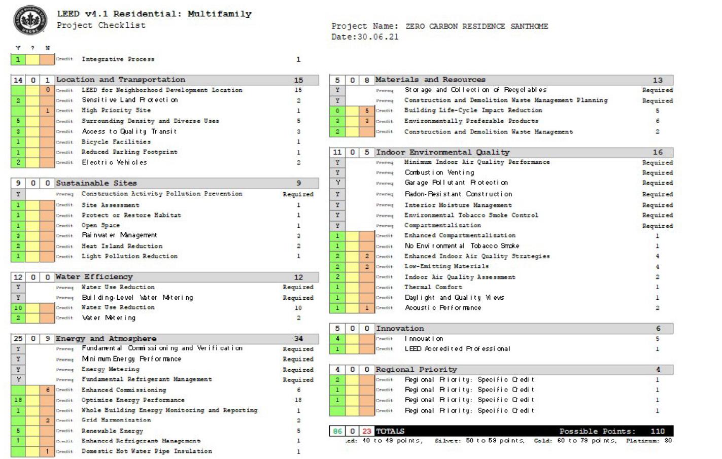
LEED V4.1 RESIDENTIAL : CHECKLIST
: 40.65 MW POWER GENERATED USING SOLAR PANELS 71% SHADING BENEFIT 6 HOURS AUTONOMY 21% WINDOW WALL RATIO 34% ENERGY EFFICIENCY 53% GREEN COVER ON SITE AREA 34 MW NET ENERGY CONSUMPTION 90% SPACE RECEIVES MORE THAN 100 LUX USING NATURAL LIGHTING 20KWH / SQM / YEAR EPI 1283 LITRES (REUSABLE WATER)
: Annual Building Energy Performance :
SUSTAINABLE STRATEGIES
TESTIMONIALS

FLOOR PLAN - SITE PLAN : LEGEND : KEY PLAN (NTS) : SCALE 1. ENTRANCE DROP-OFF 2. PAVED PATHWAY 3. WATER BODY 4. SECURITY CABIN 5. RAMP 6. BUILDING ROOF PROFILE 7. ELECTRICAL ROOM 8. PUMP ROOM 9. DRIVER’S ROOM 10. PARKING AREA 0 4 8 12 20M 5 1 6 A B C A B C D D 4 7 8 9 10 5 5 3 2 RESIDENTIAL BUILDING (G+2) AMIRTHAM RESIDENCY (G+3) BUILDING (G+1) BUILDING (G+1) KUTTY FLUSH FURNITURE CO PVT LTD RESIDENTIAL BUILDING (G+1) PAPANASAM SIVAN ROAD (8.78M) ABSOLUTE HOMES (G+1) NEIGHBOUR SIDE WALL RUSSIAN CONSULATE SANTHOME HIGH ROAD (11.47 M) TO PARRYS TO ADYAR ENTRANCE UG SUMP STP LOCATION RAINWATER SUMP PLATFORM EXIT FORESHORE ESTATE POMENADE FORESHORE ESTATE POMENADE SANTHOME HIGH RD SANTHOME HIGH RD SANTHOME HIGH RD PAPANASAM SIVAN SALAI KUTCHERY RD KARANEESWARAN KOIL STREET BEACH KARANEESWARAN KOIL STREET KARANEESWARAN KOIL STREET 1ST LN PIDAARIYAR KOIL ST LALITHA NAGAR FIRST ST PROPOSED SITE SECTIONS : SECTION - A SECTION - B SECTION - C SECTION - D


UP FLOOR PLAN - GROUND FLOOR PLAN : 1 2 3 4 5 6 9 9 10 10 11 12 13 14 15 16 17 18 21 21 22 23 19 8 8 20 7 0 1 2 3 5M LEGEND : MAIN ENTRANCE SCALE SECONDARY ENTRANCE OFFICE ENTRANCE 1. ENTRANCE 2. FORMAL LIVING 3. INFORMAL LIVING 4. WAITING LOBBY 5. FORMAL DINING 6. POOJA ROOM 7. GUEST BEDROOM 1 8. WALK IN WARDROBE 9. ATTACHED TOILET 10. COMMON TOILET 11. OFFICE AREA 12. STAIRCASE 13. LIFT 14. INFORMAL DINING 15. ISLAND KITCHEN 16. KITCHEN 17. UTILITY 18. MAID’S ROOM 19. MAID’S TOILET 20. GUEST BEDROOM 2 21. COURTYARD 22. STRUCTURAL GLAZING 23. SERVICE SHAFT SECTIONS : FORMAL LIVING - SECTION - A FORMAL LIVING - SECTION - B FORMAL LIVING - SECTION - C SHOE RACK TERRACE AREA ABOVE WITH LANDSCAPING TERRACE AREA ABOVE WITH LANDSCAPING TERRACE AREA ABOVE WITH LANDSCAPING ENTRANCE
UP FLOOR PLAN - FIRST FLOOR PLAN : 0 1 2 3 5M SCALE 1. PLAYROOM 2. BEDROOM 1 3. TOILET 4. BEDROOM 2 5. WALK-IN WARDROBE 6. ATTACHED TOILET 7. BALCONY 8. GYM 9. DOUBLE HEIGHT AREA 10. STAIRCASE 11. LIFT 12. MASTER BEDROOM 13. READING AREA 14. STUDY ROOM 15. MAINTENANCE ROOM 16. BEDROOM 3 17. TERRACE WITH LANDSCAPE 18. FEATURE WALL 19. LANDSCAPE AREA BELOW 20. SEATING AREA 21. ROOF LINE ABOVE 22. CHANDELIER 23. VERTICAL LANDSCAPE 24. SERVICE SHAFT 25. CORRIDOR 26. EXTERNAL WOODEN FINS 27. STRUCTURAL GLAZING SECTION - A DETAIL - 1 RCC SLAB HARDSCAPE (PEBBLES) OUTDOOR SEATING DETAIL - 2 LEGEND : 17 18 19 19 20 21 22 23 26 27 24 25 25 10 9 7 7 7 11 15 12 16 5 6 14 6 5 13 13 1 3 2 4 5 8 6 SECTIONS : DETAIL - 1 DETAIL - 2
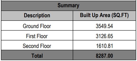
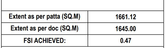
DN FLOOR PLAN - SECOND FLOOR PLAN : ELEVATIONS : 0 1 2 3 5M SCALE 1. INFORMAL LIVING 2. BAR AREA 3. OUTDOOR SITOUT 1 4. STAIRCASE 5. LIFT 6. THEATRE HALL 7. COMMON TOILET 8. CONTROL ROOM 9. OUTDOOR SITOUT 2 10. ZEN GARDEN 11. OUTDOOR SEATING 12. CHANDELIER 13. FEATURE WALL 14. SOLAR PANELS ON ROOF 15. LOWER TERRACE LEGEND : AREA & FSI DETAILS : EAST WEST NORTH SOUTH 3 1 2 4 5 7 8 6 9 10 11 12 13 14 15 1703 A-03-0041:100 30.07.20 SB CONSTRUCTION DOCUMENTATION GENERIC PLAN -TERRACE VARUN ACHARYA ZERO CARBON RESIDENCE SANTHOME PROJECT: INFORMATION: NOTES: LEGEND: N A0, #132, Saint Mary's Road, Whispering Heights, Alwarpet, Chennai - 600018 www.midoriarchitects.com GENERIC PLAN-TERRACE A-03 SCALE 1:100 004 CLIENT: DESCRIPTION: STATUS: DRAFTER: DATE: SCALE: REVISION: SHEET: JOBNO: NO. OF SOLAR PANELS - 68 nos LANDSCAPE AREA COURTYARD AREA A A
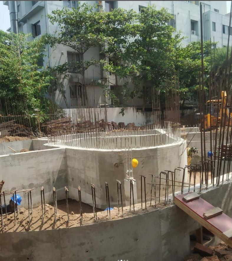
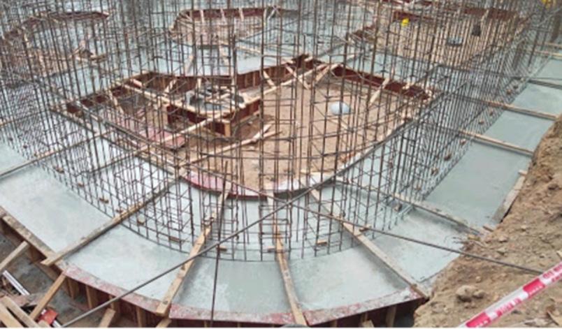
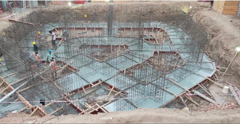
As the design has more intricate details & construction stages, needed frequent site visits and clarifications to be given on site. With the guidance of our chief architect, number of group and individual site visits were conducted. on - site scrutiny on design implications and deviations were closely examined and report were submited to the management, conclusion and solution were communicated to the contractors and builders accordingly.
Some of the site images showing the progress of raft foundation and plinth were attached. The site visits, discussion with the contractors, builders and site workers provided necessary exposure to the on site practices and constrains.
SITE VISITS & CONCEPTUAL MODEL :
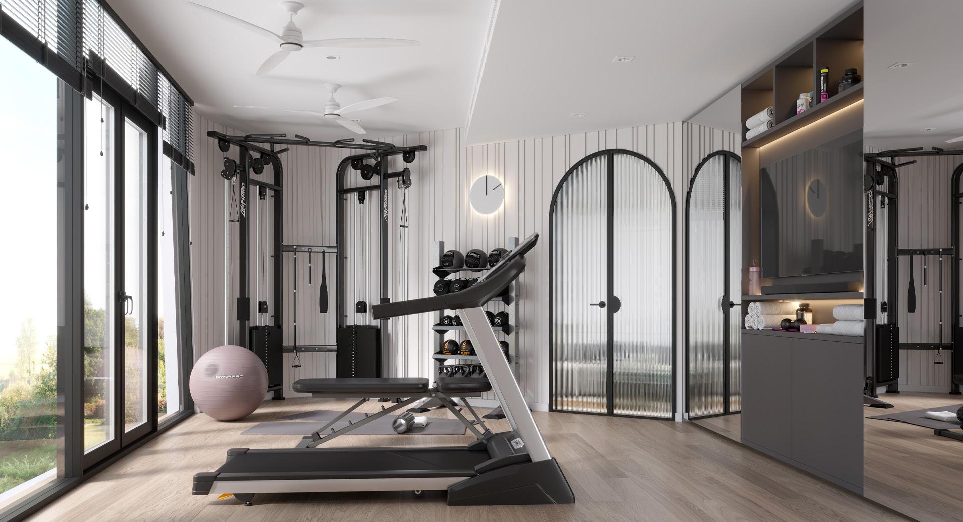
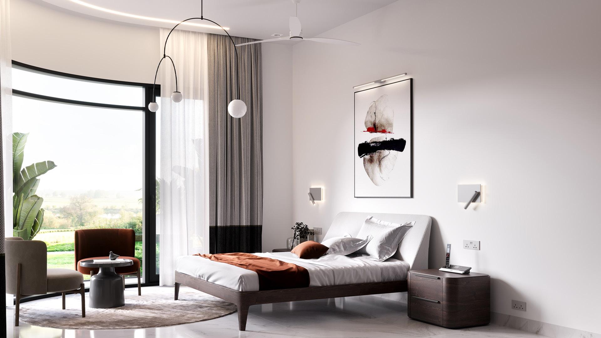
“ Stylish, Sustainable & Efficient ’’ D VISUALISATION - INTERIOR VIEWS :
AUG 20 JUN 20 JUN 20 FIRST FLOOR - MASTER BEDROOM FIRST FLOOR - GYM
3
Architect + Builder & Client.... all wrapped up in one!
AEON house represents design that results from a successful collaboration between the architect as designer and our chief architect as the owner! The oppertunities and potential for expression to expand the boundaries of building form and building space are endless when it comes to the open minded client (in this case our own chief architect).
The move towards Zero - Carbon house with more effective glazing, increased insulation, enhanced indoor environmental quality and reduction in electrical energy and water consumption - is not solely technical but illustrates how architects respond in their selection and use of low energy consumption materials.
As a team, we took up this task gleefully and wholeheartedly Aiming for Styish, Sustainable and Efficient home and designed to achieve LEED Platinum certification.
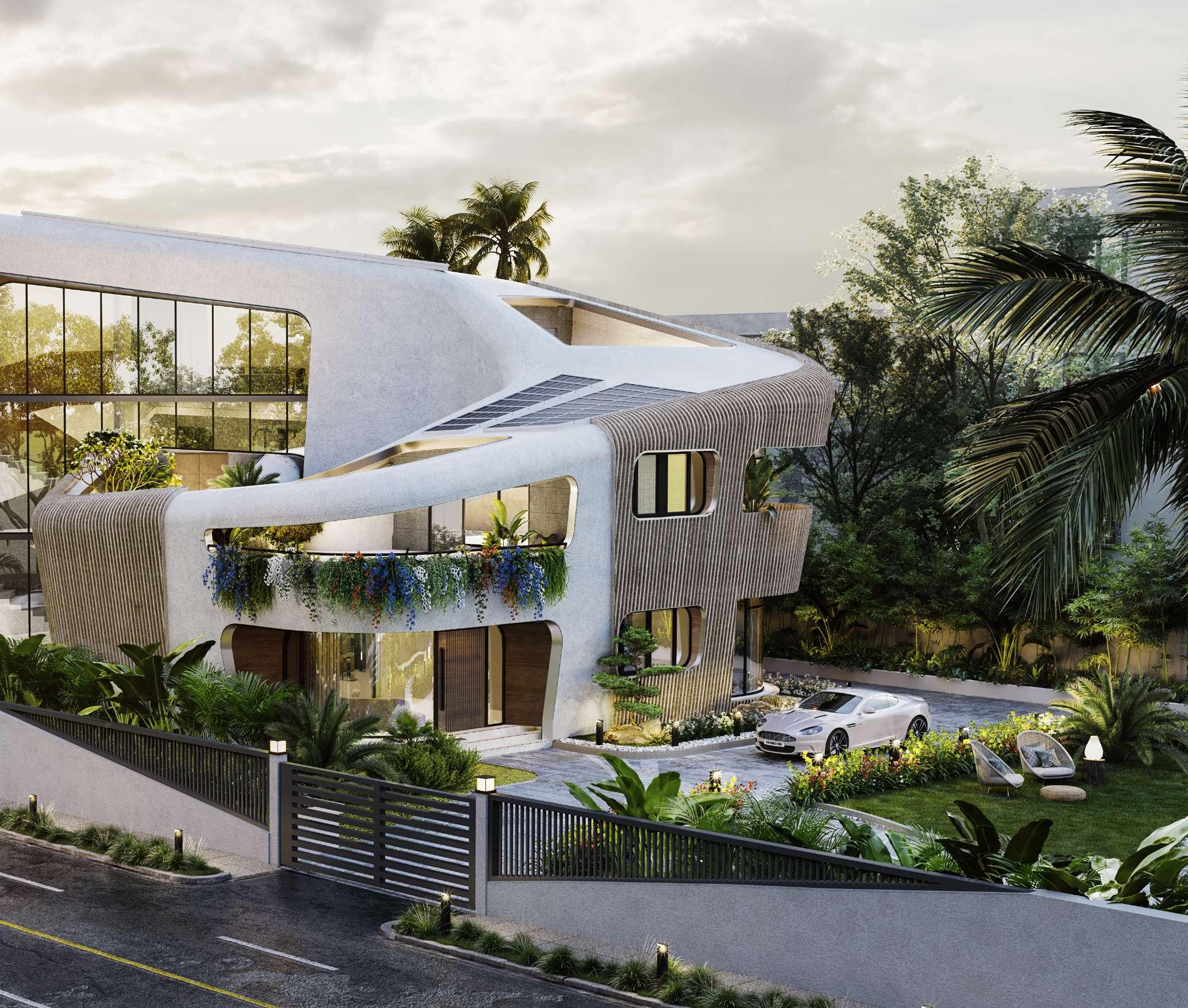
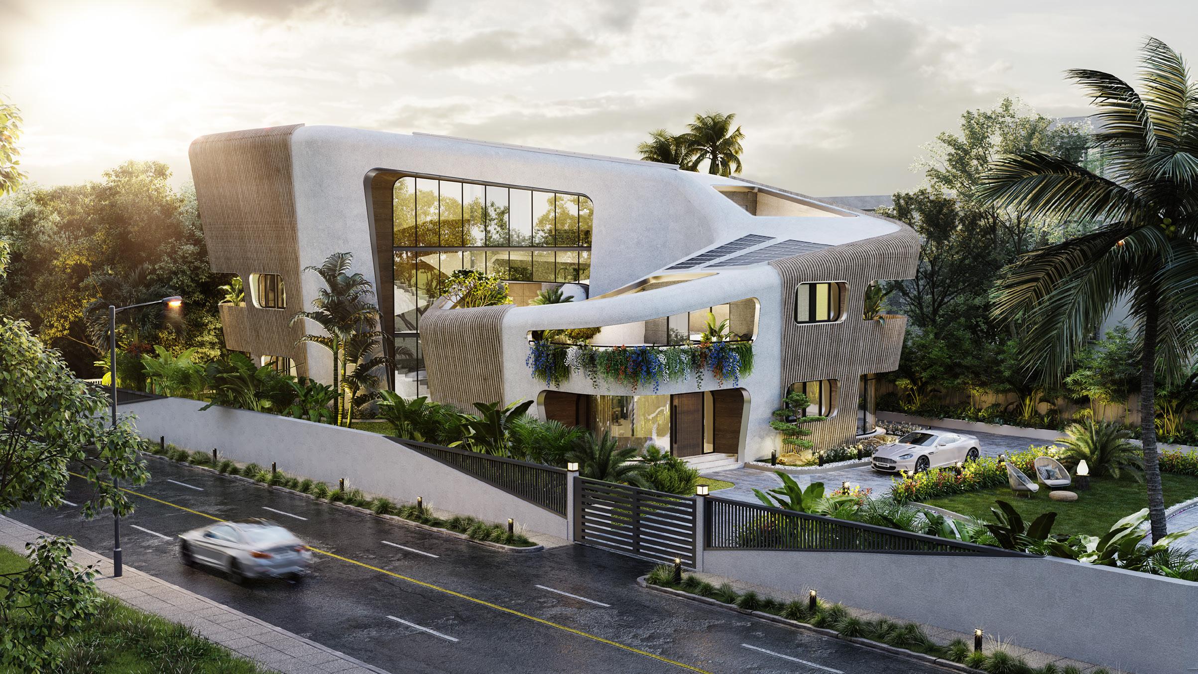
Aeon house blends craftmanship with formfinished low embodied carbon concrete techniques without compromising on the elegant form - a unique structure fashioned in the shape of Infinity - inside outside interlude. With a 23 KW photovoltaic system that taps into solar energy, a small rainwater and greywater unit and the usage of locally sourced material to shape this energy - efficient home to give it its impeccable green credebtials aiming to inspire others.
The “lit” effect of Aeon house is even more profound as the curvesand unique design ushers in daylight into the rooms evenly. The convex windows (the eyes) and the innovative roof loops blurring the lines between roof, wall and floor!
The slick recessed windows are strategically placed to allow the airflow unhindered into the kitchen, living and dining rooms through the courtyards (the lungs) for the breezy healthy indoor ambiance
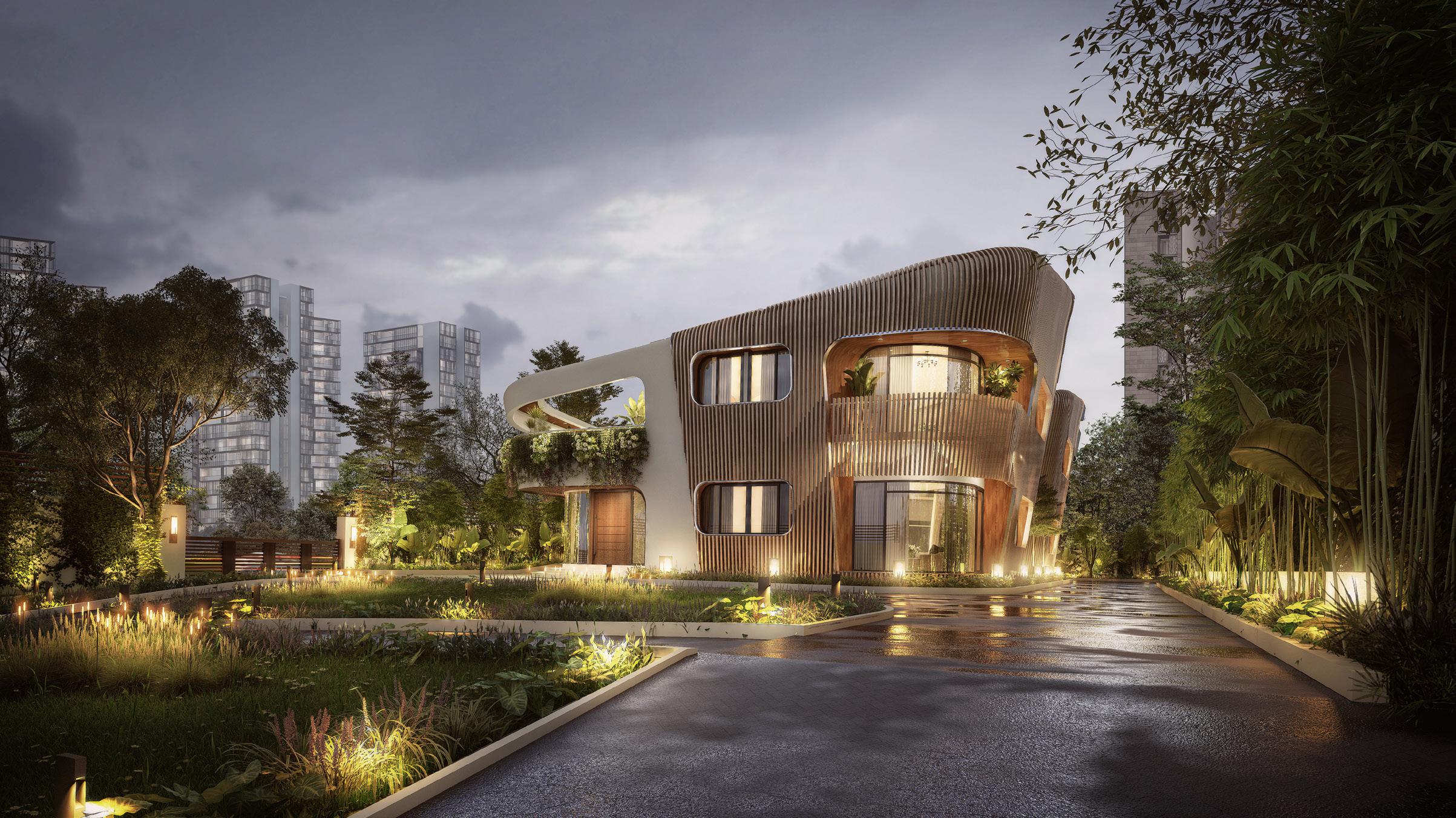
“ Aeon House ’’ D VISUALISATION - EXTERIOR VIEWS :
3


DESIGN DEVELOPMENT :
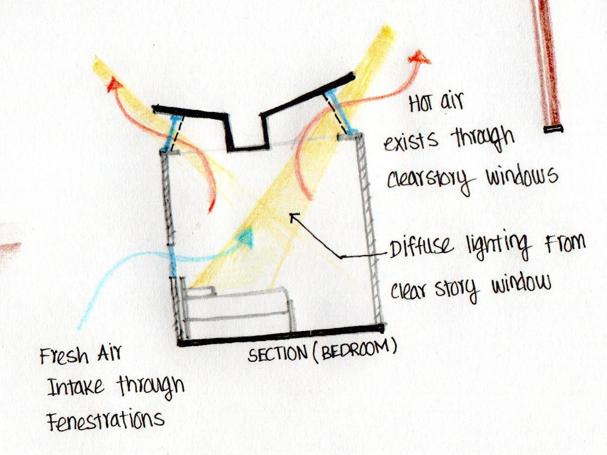
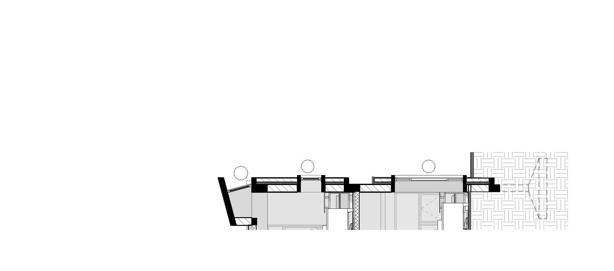
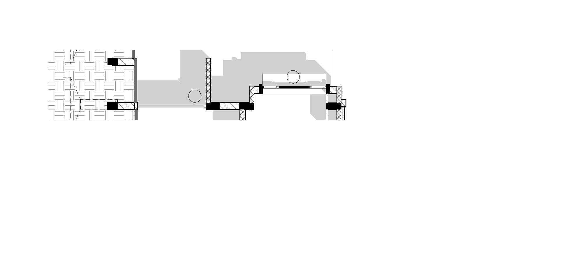
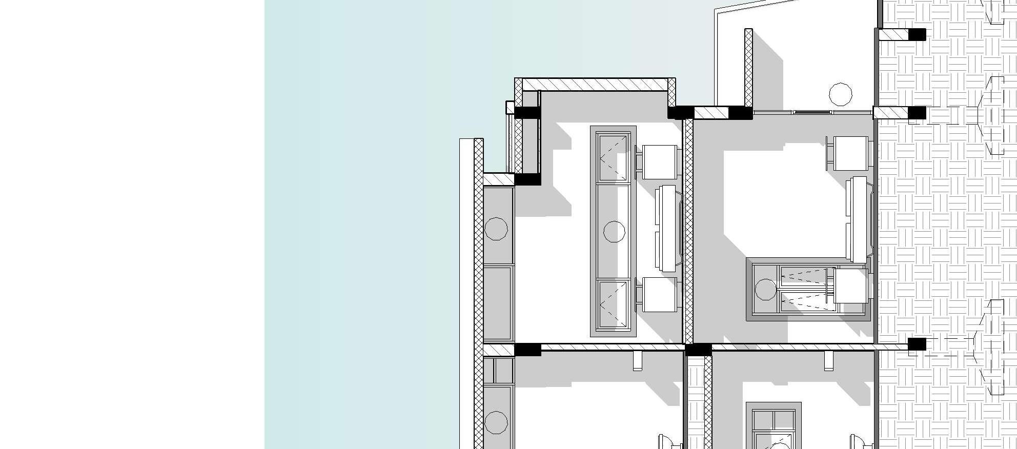
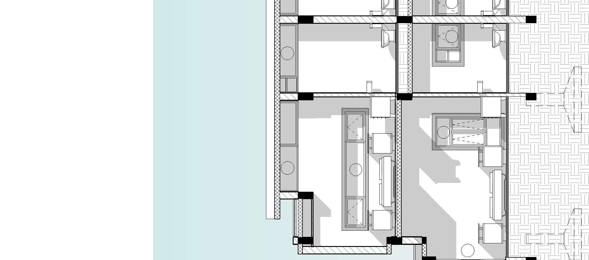
PASSIVE COOLING TECHNIQUE :
Provision of Clear story windows allows the Penetration of Diffused day lighting inside the habitalbe area. The Clear story window gets heated by Direct sun light which inturns transter the heat to the air near the roof and induce the Hot air to pass out through the windows and creates low pressure area.
To stablise this low pressure area, Cool air is sucked in to the room from the windows on the walls. This same proces repeats continuously and keeps the building interior cool compared to the outer temperature. To reduce the heat penetration through walls, Double Wall with Mineral Wool Insulation design have been incorporated.
CONCEPTUAL 3D MASSING : SECTION THROUGH BEDROOM :


PROJECT DESCRIPTION
Architect : Jeganath JB Architects
Designer : Ar Bharathi Shanmuganathan
Area : 360 m2
Year : 2021
Location : Tanjore, Tamilnadu, India
Status : Under Construction
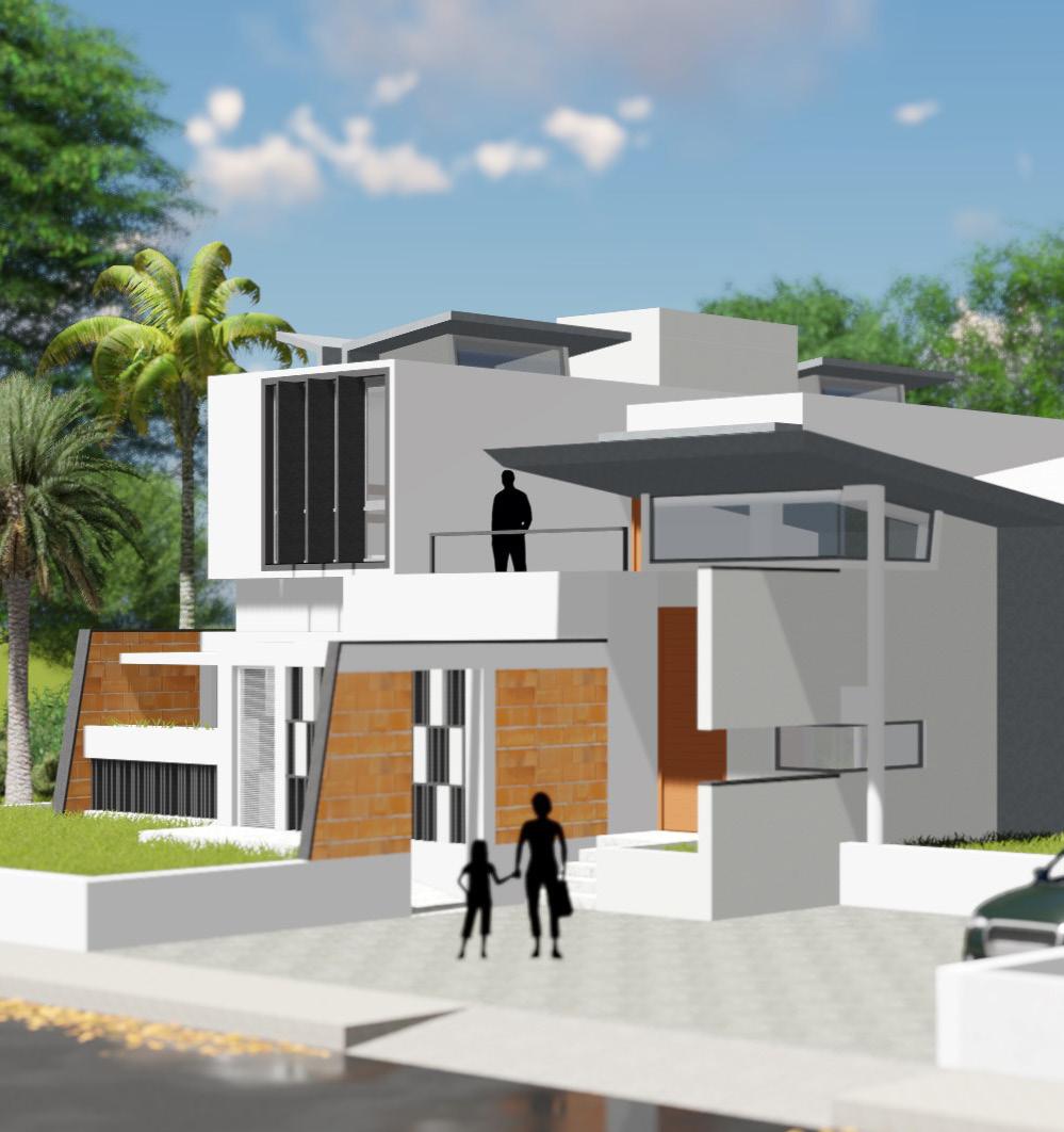
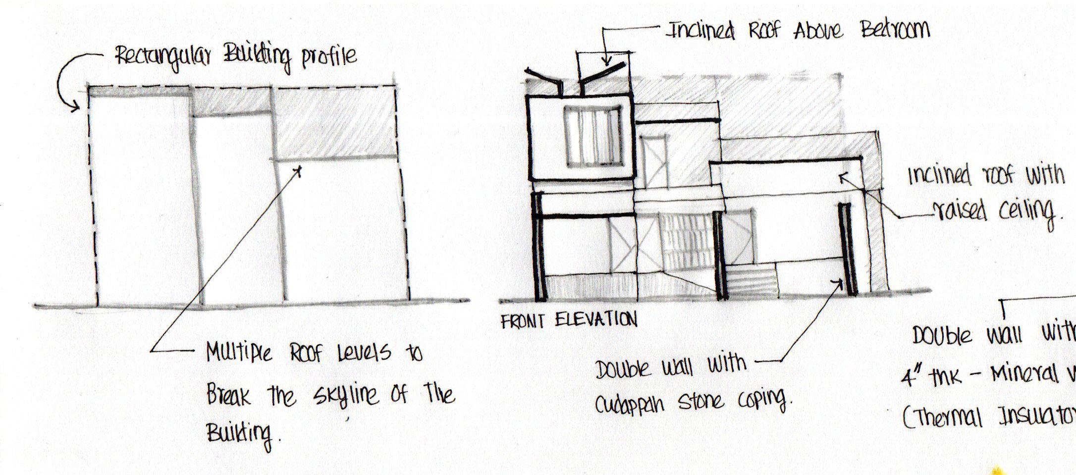
DESIGN THEORY :
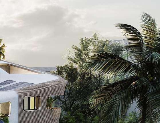
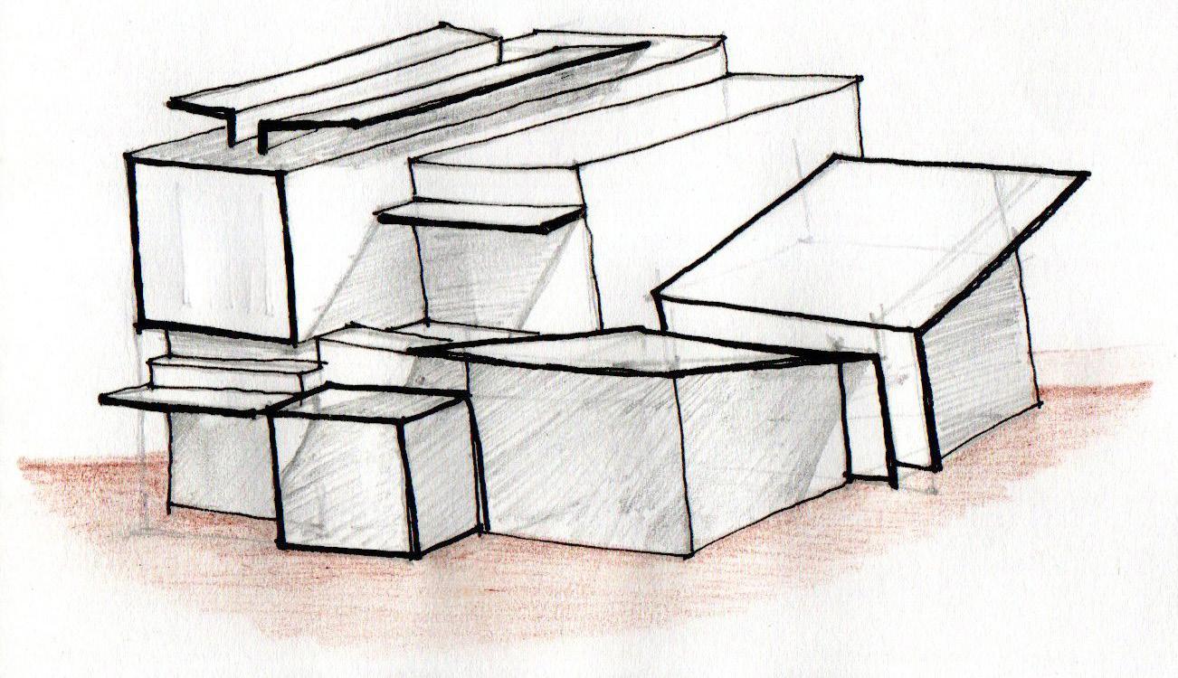
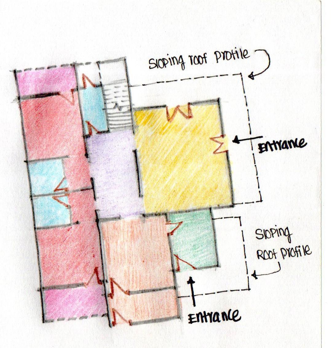
To Avoid the Monotonous Cuboid - Shaped building and to enhance the interest in facades, Multiple levels were created on the floor and Skyline of the building.
Maximum adaptation of natural lighting & ventilation through provision of clear-story windows & raised ceiling on living & office area.
Minimalistic Architecture - Style was achieved through usage of Local & Repetitive materials and finishes.
Hatch area showing Substraction of 3d Massing from Cuboid Shape to arrive on final form. This creates variations on skyline of the building facade.
Final Conceptual Sketch showing the Elavation with sloping roofs and variying skyline & Projecting double wall for thermal insulation.
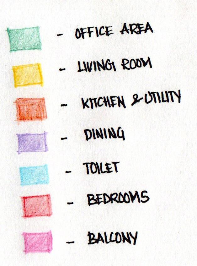
LEGEND :
CONCEPTUAL SKETCH :

02 Ms DIANA RESIDENCE
DN DN W105 1 W105 W106 W106 2 1 2 A B C D E F G H I J K L M 1 2 3 4 5 6 7 8 9 10 11 12 13 14 15 16 1 5/8" 1'-0" 3 1/4" / 1'-0" 1 5/8" 1'-0" 3 1/4" 1'-0" 2 1/8" 1'-0" 1 5/8" 1'-0" MH MH Office Entrance 3'2" 1'3" 1' 3" Ramp Slope Parking Area 3' 6" 11'6 1/2" 4' 3 1/2" Raised Planter Raised Planter Ramp Slope 8' 1" 12' 1/2" 12' 1/2" 8' 1" 5'5" 10' 3" 2' 0" 2' 0" 2' 0" 0" 39' 8" Inclined Roof Inclined Roof Inclined Roof Inclined Roof OHT Upper Terrace Area 24'3" 1' 4" 0' 9" 1' 5" 0' 11 1/2" 0' 9" 1' 9 1/2" 2' 7 1/2" 1' 5" 1' 5" 1' 5" 1' 5" Lower Terrace Area Sunshade Below 21'8" 0' 9" 11' 3" 0' 9" 2' 11 1/2" 0' 9" 34' 11" 0' 9" 22'9" 13' 3 1/2" 3' 6" 39' 8" 6" 14' 0 1/2" 6" 12' 1/2" 1' 5" 11' 9" 1' 5" 12' 1/2" 3' 6" Terrace Below 13' 2" Terrace Below 14'1" Roof AreaLiving Room Below 13'9" 24' 10 1/2" 23' 11" 2" 17'6" 18' 8" Inclined Roof Below Inclined Roof Below 0' 0" 1' 6 1/2" 0' 2" 1' 6 1/2" 0' 2" 1' 6 1/2" 0' 2" 1' 6" 0' 9" 0' 9" 1' 10" 0' 2" 1' 10 1/2" 0' 2" 10 1/2" 0' 2" 1' 10 1/2" 0' 4" Sunshade Below 10'8" Sunshade Below 10'8" 10'8" Sunshade Below Sunshade Below 12'9" Sitout Area 3' 2 1/2" Lobby 3' 2 1/2" 7' 3" 0' 9 1/2" 5' - 5 1/2" 1' 2 1/2" 2' 0 1/2" 10' - 2 1/2" 1' - 5" 5' 1" 10' - 3" 3' 10" 10' 6" 7' 6" 1' - 11 1/2" 1' - 0 1/2" 8' 6" 12' 8" 4' 8" 7'4" 4'8" 6' 5 1/2" 3'10 1/2" 2'2" 1' 6" 1'1" 5'2" 1'6" 9'0" 8'0" 75'0" 27' 9 1/2" 10' - 2" 115' 0" 6'11" 1 W -107 2 W -107 1 W -108 2 W -108 1 W -109 2 W -109 Access Road W -103 4 NOTES PRINTS REVISIONS DISCLAIMER PROJECT CLIENT DOCUMENT STATUS 1. Please Refer all R.C.C details in conjunction with Structural Drawing 2. All levels are given with respect to centre line of external road taken as ± 0000. 3. Framing to be as per relevant architectural & structural drawings. 5. Any discrepancy to be brought to the notice of the architect. 6. Drawings to be read & not scaled.All dimensions are in feet and inches. This document and its contents are the copyright of JEGANATH JB ARCHITECTS. Any party receiving this document does so in confidence and agrees that any of the information contained herein shall not be reproduced in whole or in part or disclosed to others without the prior written consent of the architect. JEGANATH JB ARCHITECTS Tel : 04442069848 Email jeganathjb@gmail.com Web : www.jeganathjbarchitects. carbonmade.com Address: No.1, 4th floor, Habib Complex, Durghabai Deshmukh Road, R.A.Puram, Chennai28. DRAWING TITLE DATE SCALE (A1) DRAWN BY PROJECT NO. DRAWING NO. REVISION NO. CHECKED AND APPROVED BY Ar. Jeganath.J.Balakrishnan Ar. Bharathi S NORTH 3/16" = 1'0" Residence For Ms. Diana Mr. Xavier Maxlin Working Drawing Site Plan 23/03/21 246DRT W100 3/16" = 1'-0" 1 00 Site Plan
DN DN DN UP A B C D E F G H I J K L M 1 2 3 4 5 6 7 8 9 10 11 12 13 14 15 16 138 SF Office Area 1 405 SF Living Room 2 179 SF Dining Room 3 44 SF Store Room 4 228 SF Kitchen 5 224 SF Bedroom 1 6 47 SF Toilet 1 7 50 SF Toilet 2 8 190 SF Bedroom 2 9 16 SF Wash Area 1 10 30 SF Common Toilet 11 14 SF Wash Area 2 12 99 SF Utility Area 13 125 SF Staircase Area 14 57 SF Balcony 1 16 53 SF Balcony 2 17 230 SF Sitout Area 18 Wardrobe Wardrobe Storage Storage Island Counter Double Height Area Double Height Area Sloping Roof Above Sloping Roof Above Sloping Roof Profile Sloping Roof Profile 3'2 1/2" 3' 3" 3'2 1/2" 3'2 1/2" 3' 3" 3'2 1/2" 3'2 1/2" 3' 3" 3'2 1/2" 3'3" 3'3" 3' 2 1/2" 3'2 1/2" Main Entrance 3'2 1/2" Office Entrance Lobby 3'2" 1'3" 1'3" 3'2 1/2" Raised Planter Raised Planter Raised Planter Raised Planter Ramp Slope Ramp Slope Parking Area Counter 1 Counter 2 Fridge Location 4' 9" 10' 1/2" 0' 4" 3' 0" 0' 4" 1' 1/2" 11' 11" 15' 11" 7' 3" 4' 8 1/2" 11' 11" 1' 6" 0' 9" 3' 10 1/2" 0' 5" 2' 1/2" 2' 11 1/2" 0' 5" 3' 10 1/2" 6'10" 6'10" 0' 8" 3' 0" 8" 2' 0" 0' 9" 2' 0" 2' 0" 3' 0" 0' 8" 7' 3" 4' 8" 11' 11" 4' 1/2" 0' 9" 7' 11 1/2" 4" 3' 0" 4" 1' 3 1/2" 12' 11" 0' 9" 15'11" 6' 3" 6'9" 6" 1'5 1/2" 15' 0" 1' 5 1/2" 4' 0" 8' 0" 4' 0 1/2" 6' 3" 22' 1/2" 4' 0" 6' 1/2" 4' 0" 7' 7" 22' 1/2" 10' 7" 0" 0' 4" 13' 11" 0' 7" 3' 3" 6' 1" 9' 11 1/2" 10' 4" 3' 3" 0' 4" 13' 10" 3' 3" 4" 17' 5" 3" 3' 3" 10' 6" 3' 8" 2' 10" 0' 8" 3' 0" 0' 5" 3' 4" 2'0" 3'2 1/2" 3'1/2" 0'3" 3' 3" 5' 7" 4' 1 1/2" 4' 7 1/2" 8'9" 3' 3" 7' 7" 3' 3" 1' 6" 0' 3" 1' 2" 2' 6" 1'0" 4' 1 1/2" 2' 5 1/2" 0' 9" 5' 1" 0' 9" 0' 9" 16' 11" 2' 1 1/2" 1' 2" 2' 6" 0' 3" 3' 11 1/2" 3' 1/2" 7' 7" 4' 0 1/2" 3' 11" 4" 3' 6" 12' 4" 4' 4" 4'6" 0' 9" 4'4" 0' 9" 6' 9" 0" 2' 0" 4' 8 1/2" 5' 1" 5' 0" 11" 10' 2 1/2" 15' 4" 11" 6' 1/2" 0' 5" 0' 2 1/2" 0' 9" 0' 5" 0' 2 1/2" 0' 9" 0' 5" 0' 3" 0'9" 0' 5" 0' 3" 0' 9" 2' 1" 4" 14' 0" 0' 4" 11" 7' 3" Lobby 6 4 3 2 8 10 7 9 15 14 13 12 16 11 1 5 CW1 CW2 W2 W3 W4 W5 SW1 W6 W7 W8 W1 8' 6" 1' 0 1/2" 1' 11 1/2" 7' 6" 10' 6" 3' 10" 10' 3" 5' 1" 1' 5" 10' 2 1/2" 2' 0 1/2" 1' - 2 1/2" 5' 5 1/2" 0' - 9 1/2" 7' 3" 12'8" 4' 8" 7'4" 4'8" 6'5 1/2" 3'10 1/2" 2'2" 1'6" 1'1" 5'2" 1' 6" 9'0" Duct Duct 1 W -107 2 W -107 1 W -108 2 W -108 1 W -109 2 W -109 3'3" W -103 3 NOTES PRINTS REVISIONS DISCLAIMER PROJECT CLIENT DOCUMENT STATUS 1. Please Refer all R.C.C details in conjunction with Structural Drawing 2. All levels are given with respect to centre line of external road taken as ± 0000. 3. Framing to be as per relevant architectural & structural drawings. 5. Any discrepancy to be brought to the notice of the architect. 6. Drawings to be read & not scaled.All dimensions are in feet and inches. This document and its contents are the copyright of JEGANATH JB ARCHITECTS. Any party receiving this document does so in confidence and agrees that any of the information contained herein shall not be reproduced in whole or in part or disclosed to others without the prior written consent of the architect. JEGANATH JB ARCHITECTS Tel : 04442069848 Email : jeganathjb@gmail.com Web : www.jeganathjbarchitects. carbonmade.com Address: No.1, 4th floor, Habib Complex, Durghabai Deshmukh Road, R.A.Puram, Chennai28. DRAWING TITLE DATE SCALE (A1) DRAWN BY PROJECT NO. DRAWING NO. REVISION NO. CHECKED AND APPROVED BY Ar. Jeganath.J.Balakrishnan Ar. Bharathi S NORTH 1/4" = 1'0" Residence For Ms. Diana Mr. Xavier Maxlin Working Drawing Ground Floor Plan 23/03/21 246DRT W101 1/4" = 1'-0" 1 01 Ground Floor
DN DN DN UP A B C D E F G H I J K L M 1 2 3 4 5 6 7 8 9 10 11 12 13 14 15 16 224 SF Bedroom 1 6 57 SF Balcony 1 16 99 SF Utility Area 13 47 SF Toilet 1 7 50 SF Toilet 2 8 190 SF Bedroom 2 9 179 SF Dining Room 3 44 SF Store Room 4 228 SF Kitchen 5 138 SF Office Area 1 405 SF Living Room 2 125 SF Staircase Area 14 53 SF Balcony 2 17 14 SF Wash Area 2 12 30 SF Common Toilet 11 16 SF Wash Area 1 10 230 SF Sitout Area 18 Wardrobe Wardrobe Storage Storage Island Counter Double Height Area Double Height Area Sloping Roof Above Sloping Roof Above Sloping Roof Profile Sloping Roof Profile Main Entrance Office Entrance Ramp Slope Ramp Slope Parking Area Counter 1 Counter 2 Lobby Duct 1 W -107 2 W -107 1 W -108 2 W -108 1 W -109 2 W -109 Duct Raised Planter Raised Planter Raised Planter 8' 6" 1' 0 1/2" 1' - 11 1/2" 7' 6" 10' 6" 3' 10" 10' 3" 5' - 1" 1' 5" 10' 2 1/2" 2' 0 1/2" 1' 2 1/2" 5' - 5 1/2" 0' 9 1/2" 7' - 3" 12'8" 4' 8" 7'4" 4'8" 6' 5 1/2" 3'10 1/2" 2'2" 1' 6" 1'1" 5'2" 1' 6" 9'0" Study Table Study Table Fridge Location NOTES PRINTS REVISIONS DISCLAIMER PROJECT CLIENT DOCUMENT STATUS 1. Please Refer all R.C.C details in conjunction with Structural Drawing 2. All levels are given with respect to centre line of external road taken as ± 0000. 3. Framing to be as per relevant architectural & structural drawings. 5. Any discrepancy to be brought to the notice of the architect. 6. Drawings to be read & not scaled.All dimensions are in feet and inches. This document and its contents are the copyright of JEGANATH JB ARCHITECTS. Any party receiving this document does so in confidence and agrees that any of the information contained herein shall not be reproduced in whole or in part or disclosed to others without the prior written consent of the architect. JEGANATH JB ARCHITECTS Tel : 04442069848 Email jeganathjb@gmail.com Web : www.jeganathjbarchitects. carbonmade.com Address: No.1, 4th floor, Habib Complex, Durghabai Deshmukh Road, R.A.Puram, Chennai28. DRAWING TITLE DATE SCALE (A1) DRAWN BY PROJECT NO. DRAWING NO. REVISION NO. CHECKED AND APPROVED BY Ar. Jeganath.J.Balakrishnan Ar. Bharathi S NORTH 1/4" = 1'0" Residence For Ms. Diana Mr. Xavier Maxlin Working Drawing Ground FloorFurniture Plan 23/03/21 246DRT W101 A 1/4" = 1'-0" 1 02 Ground Floor -Furniture
DN DN DN A B C D E F G H I J K L M 1 2 3 4 5 6 7 8 9 10 11 12 13 14 15 16 17 18 19 20 21 190 SF Bedroom 4 19 50 SF Toilet 4 20 47 SF Toilet 3 21 200 SF Bedroom 3 22 107 SF Corridor 23 232 SF Terrace Area 24 Wardrobe Wardrobe Double Height Area Double Height Area Living Area Below Office Area Below 13'2" 14' 3" 14'3" 14'3" 14' 2 1/2" 14'2 1/2" 15'1" 15'1" Rised Platform Rised Platform 2' 9 1/2" 0' 4" 2' 1" 0'2" 2' 1" 0' 2" 2'1" 0' 2" 2' 1" 11' 11" 1/2" 0' 4" 11' 6" 0' 4" 7" 14' 10 1/2" 7' 3" 4' 8" 11' 11" 0' 8" 3' 0" 8" 2' 0" 6'10" 11" 7' 3" 0' 8" 3' 0" 2' 0" 2' 0" 0' 1/2" 0' 4" 11' 6" 0' 4" 2' 0" 14' 1/2" 2' 9" 0'4" 2' 1" 0' 2" 2' 1" 0' 2" 2' 1" 0' 2" 2'1" 11'11 1/2" 10' 1/2" 3' 3" 7' 7" 3' 6" 0'4 1/2" 3'0" 1' 3" 3' 11" 1' 6 1/2" 0'2" 1' 6 1/2" 0' 2" 1' 6 1/2" 0' 2" 1' 6" 0' 9" 0' 9" 10" 0' 2" 1' 10 1/2" 0' 2" 10 1/2" 0' 2" 1' 10 1/2" 0' 4" 5' 4 1/2" 7' 3" 4' 8" 3' 0" 4' 0" 0' 9" 1' 9 1/2" 8" 11' 8" 11'7 1/2" 3' 2" 14' 1" Raised Planter Terrace Area Roof AreaLiving Room Below Sloping Roof Profile Sloping Roof Profile Handrail Handrail Roof Extension Profile 8' 6" 1' - 0 1/2" 1' 11 1/2" 7' 6" 10' 6" 3' 10" 10' 3" 5' 1" 1' 5" 10' 2 1/2" 2' 0 1/2" 1' - 2 1/2" 5' 5 1/2" 0' - 9 1/2" 7' 3" 12'8" 4' 8" 7'4" 4'8" 6'5 1/2" 3'10 1/2" 2'2" 1'6" 1' 1" 5'2" 1' 6" 9'0" SW1 W9 W10 SW2 SW3 SW4 W11 W12 Duct Duct Handrail 11'7" Midlanding Cudappah Stone Coping on Top of Double Wall Cudappah Stone Coping on Top of Double Wall Cudappah Stone Coping on Top of Double Wall Cudappah Stone Coping on Top of Double Wall Kota Stone Wall Cudappah Stone Coping on Top of Wall 13' 9" 1 W -107 2 W -107 1 W -108 2 W -108 1 W -109 2 W -109 NOTES PRINTS REVISIONS DISCLAIMER PROJECT CLIENT DOCUMENT STATUS 1. Please Refer all R.C.C details in conjunction with Structural Drawing 2. All levels are given with respect to centre line of external road taken as ± 0000. 3. Framing to be as per relevant architectural & structural drawings. 5. Any discrepancy to be brought to the notice of the architect. 6. Drawings to be read & not scaled.All dimensions are in feet and inches. This document and its contents are the copyright of JEGANATH JB ARCHITECTS. Any party receiving this document does so in confidence and agrees that any of the information contained herein shall not be reproduced in whole or in part or disclosed to others without the prior written consent of the architect. JEGANATH JB ARCHITECTS Tel : 04442069848 Email : jeganathjb@gmail.com Web : www.jeganathjbarchitects. carbonmade.com Address: No.1, 4th floor, Habib Complex, Durghabai Deshmukh Road, R.A.Puram, Chennai28. DRAWING TITLE DATE SCALE (A1) DRAWN BY PROJECT NO. DRAWING NO. REVISION NO. CHECKED AND APPROVED BY Ar. Jeganath.J.Balakrishnan Ar. Bharathi S NORTH 1/4" = 1'0" Residence For Ms. Diana Mr. Xavier Maxlin Working Drawing First Floor Plan 23/03/21 246DRT W102 1/4" = 1'-0" 1 03 First Floor
A B C D E F G H I J K L M 1 2 3 4 5 6 7 8 9 10 11 12 13 14 15 16 200 SF Bedroom 3 22 47 SF Toilet 3 21 50 SF Toilet 4 20 190 SF Bedroom 4 19 107 SF Corridor 23 232 SF Terrace Area 24 Double Height Area Double Height Area Living Area Below Office Area Below Terrace Area Handrail Handrail Roof AreaLiving Room Below Raised Planter Wardrobe Wardrobe Midlanding 1 W -107 2 W -107 1 W -108 2 W -108 1 W -109 2 W -109 Sloping Roof Profile Sloping Roof Profile Roof Extension Profile Cudappah Stone Coping on Top of Double Wall Cudappah Stone Coping on Top of Double Wall Cudappah Stone Coping on Top of Double Wall Cudappah Stone Coping on Top of Double Wall Kota Stone Wall Cudappah Stone Coping on Top of Wall Study Table 8' 6" 1' 0 1/2" 1' - 11 1/2" 7' 6" 10' 6" 3' 10" 10' 3" 5' - 1" 1' 5" 10' 2 1/2" 2' 0 1/2" 1' 2 1/2" 5' - 5 1/2" 0' 9 1/2" 7' - 3" 12'8" 4' 8" 7'4" 4'8" 6' 5 1/2" 3'10 1/2" 2'2" 1' 6" 1' 1" 5'2" 1' 6" 9'0" NOTES PRINTS REVISIONS DISCLAIMER PROJECT CLIENT DOCUMENT STATUS 1. Please Refer all R.C.C details in conjunction with Structural Drawing 2. All levels are given with respect to centre line of external road taken as ± 0000. 3. Framing to be as per relevant architectural & structural drawings. 5. Any discrepancy to be brought to the notice of the architect. 6. Drawings to be read & not scaled.All dimensions are in feet and inches. This document and its contents are the copyright of JEGANATH JB ARCHITECTS. Any party receiving this document does so in confidence and agrees that any of the information contained herein shall not be reproduced in whole or in part or disclosed to others without the prior written consent of the architect. JEGANATH JB ARCHITECTS Tel : 04442069848 Email jeganathjb@gmail.com Web : www.jeganathjbarchitects. carbonmade.com Address: No.1, 4th floor, Habib Complex, Durghabai Deshmukh Road, R.A.Puram, Chennai28. DRAWING TITLE DATE SCALE (A1) DRAWN BY PROJECT NO. DRAWING NO. REVISION NO. CHECKED AND APPROVED BY Ar. Jeganath.J.Balakrishnan Ar. Bharathi S NORTH 1/4" = 1'0" Residence For Ms. Diana Mr. Xavier Maxlin Working Drawing First FloorFurniture Plan 23/03/21 246DRT W102 A 1/4" = 1'-0" 1 04 First Floor -Furniture


A B C D E F G H I J K L 2 3 4 5 6 7 8 9 10 11 12 13 14 15 Cutout Below Cutout Below Cutout Below Cutout Below Cutout Below Cutout Below Sloping Roof Profile Sloping Roof Profile Sloping Roof Profile Sloping Roof Profile Duct Duct OHT (5'8" x 4'10" x 2'7") Without Clear Board Of 2000L Capacity OHT (5'8" x 4'10" x 2'7") Without Clear Board Of 2000L Capacity MH MH 0" 2' 0" Lower Terrace Area Upper Terrace Area 24'3" 22'9" 0' 9" 11' 3" 0' 9" 9" 34' 11" 0' 9" 4' 6" 8' 1 1/2" 1' 5" 4' 6" 1' 5" 8' 1 1/2" 1' 5" 1' 5" 2' 7" 2' 6" 2' 6" 2' 6" 4' 9" 1' 5" 4' 9" 1' 5" 9' 2" 9' 2" 9' 2" 7' 0" 7' 0" 9' 2" 4" 0' 9" 3' 5" 0' 11 1/2" 0' 9" 3' 9" 24' 10 1/2" 23' 11" 3' 2" 17' 6" 18' 8" 3' 0" 12' 7" Sunshade Below 21'8" 2 1/8" 1'-0" 1 5/8" 1'-0" Inclined Roof Below 14' 0 1/2" 5' 5 1/2" 0' 9" 9' 1" 0' 9" 11" 9" 6' 11" 0' 9" 9' 1" 0' 9" 5' 1/2" Inclined Roof Below Terrace Below Terrace Below 1' - 0 1/2" 1' 11 1/2" 7' 6" 10' 6" 3' 10" 10' 3" 5' 1" 1' - 5" 10' 2 1/2" 2' 0 1/2" 1' - 2 1/2" 5' - 5 1/2" 0' - 9 1/2" 12' 8" 4'8" 7' 4" 4'8" 6' 5 1/2" 3'10 1/2" 2'2" 1' 6" 1' 1" 5'2" 1' 6" 1 W -107 2 W -107 1 W -108 2 W -108 1 W -109 2 W -109 W12 W13 W14 W15 W16 W17 Road 0'0" Ground Floor 3'3" First Floor 14'3" Existing Ground Level 0'9" Lower Terrace 22'9" Upper Terrace 24'3" Foundation Base4'3" A 27' 1 1/2" W2 W9 W12 0' 6" 6' 6" 0' 11" 2' 6" 2' 5 1/2" 3' 0" 2' 0" 3 "4/1 / 10 4' 8" 14'3" 3'3" Clear Story Window Window Window 8" thk RCC Slab Projection on Top of The Beam 8" thk Porotherm Brick Wall 4" thk Porotherm Brick Wall Mineral WoolThermal Insulation of 4" Thk 2" thk Cudappah Stone Coping RCC Slab Projection 3'0" Isolated Footing Foundation 8" thk RCC Slab Projection on Top of The Plinth Beam B C D E 2 3 4 3 2 1 Ramp Slope 0' 9" 7' 1" 3' 3" 5'7" 6' 3" 3' 6" 12' 4" 4' 8" W1 3' 2" 3'3 1/2" 3' 2 1/2" 1'3" 99 SF Utility Area 13 5' 1" Dry Area Wet Area Lobby Parking Area 4'8" 7'4" 4'8" 1' 0 1/2" 1' - 11 1/2" 1/2" thk Cudappah Stone Fixed Vertically on 2" thk Cudappah Slab 2" thk Cudappah Slab Supported By 9" thk Brick Wall 9" thk Brick Wall Semi Enclosed Utility Area With Cudappah Stone Fixed To Roof Beam 8"thk Porotherm Wall B C D E 2 3 4 1' 0 1/2" 1' 11 1/2" 4'8" 7' 4" 4' 8" 1 5/8" 1'-0" Ramp Slope 3' 6" 4' 8" 11'6 1/2" 3'2" Parking Area Inclined Roof Office Entrance 11'7" 1/2"thk Cudappah Stone Fixed Vertically To Beam Bottom 8"thk Porotherm Wall Cudappah Stone Coping on Top of 8"thk Porotherm Wall Handrail Landscape Area Raised Planter NOTES PRINTS REVISIONS DISCLAIMER PROJECT CLIENT DOCUMENT STATUS 1. Please Refer all R.C.C details in conjunction with Structural Drawing 2. All levels are given with respect to centre line of external road taken as ± 0000. 3. Framing to be as per relevant architectural & structural drawings. 5. Any discrepancy to be brought to the notice of the architect. 6. Drawings to be read & not scaled.All dimensions are in feet and inches. This document and its contents are the copyright of JEGANATH JB ARCHITECTS. Any party receiving this document does so in confidence and agrees that any of the information contained herein shall not be reproduced in whole or in part or disclosed to others without the prior written consent of the architect. JEGANATH JB ARCHITECTS Tel : 04442069848 Email : jeganathjb@gmail.com Web : www.jeganathjbarchitects. carbonmade.com Address: No.1, 4th floor, Habib Complex, Durghabai Deshmukh Road, R.A.Puram, Chennai28. DRAWING TITLE DATE SCALE (A1) DRAWN BY PROJECT NO. DRAWING NO. REVISION NO. CHECKED AND APPROVED BY Ar. Jeganath.J.Balakrishnan Ar. Bharathi S NORTH 1/4" = 1'0" Residence For Ms. Diana Mr. Xavier Maxlin Working Drawing Lower Terrace Plan 23/03/21 246DRT W103 1/4" = 1'-0" 1 05 Lower Terrace 1/4" = 1'-0" 2 Section 7 -Callout 1 1/4" = 1'-0" 3 Utility Area -Detail Plan 1/4" = 1'-0" 4 Utility Area -Roof Plan Sheet List Project Number Sheet Number Sheet Name Issue Date 246DRTW100Site Plan 23/03/21 246DRTW101Ground Floor Plan23/03/21 246DRTW101 AGround FloorFurniture Plan 23/03/21 246DRTW102First Floor Plan23/03/21 246DRTW102 AFirst FloorFurniture Plan 23/03/21 246DRTW103Lower Terrace Plan23/03/21 246DRTW104Upper Terrace Plan23/03/21 246DRTW105South & East Elevation07/12/21 246DRTW106North & West Elevation07/12/21 246DRTW107Section 1 & 2 07/12/21 246DRTW108Section 3 & 4 07/12/21 246DRTW109Section 5 & 6 07/12/21 246DRTW110Prespective Views 121/01/22 246DRTW111Prespective Views 221/01/22 NOTES:1. ALL LEVELS WITH RESPECTED TO +0'0" ROAD LEVEL. 2. ALL BRICK WORK TO BE 200 M.M. 3. ALL TOILET SLAB ARE DROPPED BY 1' 4. 2" OF FLOORING MARGIN TO BE TAKEN. 5. ALL DIMENSIONS TO BE TALLIED ON SITE. DISCREPANCIES IF ANY ARE TO BE BROUGHT TO THE IMMEDIATE NOTICE OF THE ARCHITECT. 6. FOR LOCATION OF GRIDS IN COLUMN, REFER COLUMN SETOUT PLAN.
A B C D E F G H I J K L 2 3 4 5 6 7 8 9 10 11 12 13 14 15 MH MH 8' 1" 12' 6 1/2" 12' - 6 1/2" 8' 1" 5'5" 10' 3" 2'0" 2' 0" 2'0" 2' 0" 4'6" 39' 8" 1 5/8" 1'-0" 1 5/8" 1'-0" 3 1/4" 1'-0" 3 1/4" / 1'-0" Inclined Roof Inclined Roof Inclined Roof Inclined Roof OHT Lower Terrace Area Upper Terrace Area Sunshade Below Inclined Roof Below Inclined Roof Below Terrace Below 24'3" 21'8" 0'9" 11' 3" 0' 9" 2' - 11 1/2"0' 9" 34' 11" 0' 9" 24'11" 23' 11" 18' - 8" 17'6" 1 5/8" / 1'-0" 2 1/8" 1'-0" Terrace Below 3' 2" 22'9" 1' 4" 0' - 9" 1' 5" 0' - 11 1/2" 0' 9" 1' 9 1/2" 2' 7 1/2" 1' - 5" 1' 5" 1'5" 1'5" 13'3 1/2" 3' - 6" 39' 8" 3' 6" 14'0 1/2" 3' 6" 12' 6 1/2" 1' - 5" 11' 9" 1' 5" 12' - 6 1/2" 3' - 6" 1 W -107 2 W -107 1 W -108 2 W -108 1 W -109 2 W -109 1' 0 1/2" 1' - 11 1/2" 7' 6" 10' 6" 3' 10" 10' 3" 5' - 1" 1' 5" 10' 2 1/2" 2' - 0 1/2" 1' 2 1/2" 5' 5 1/2" 0' 9 1/2" 12' 8" 4'8" 7' 4" 4'8" 6'5 1/2" 3'10 1/2" 2'2" 1' 6" 1' 1" 5'2" 1' 6" Road 0'0" Ground Floor 3'3" First Floor 14'3" Existing Ground Level 0'9" Lower Terrace 22'9" Upper Terrace 24'3" Foundation Base4'3" 12 13 53 SF Balcony 2 17 1/2" 0' 5" 3' 5" 7' 0" 0' 10" 7' 4" 3' 2 1/2" 10'8" 23' 11" CW2 SW2 2" thk Cudappah Stone Coping 6" thk Parapet Projection Gypsum False Ceiling 2" Cudappah Stone Projection Window RCC Projection Structural Beam UPVC Curtain Wall 5"thk Slab Projection Plinth Beam Isolated FootingFoundation Inverted Beam NOTES PRINTS REVISIONS DISCLAIMER PROJECT CLIENT DOCUMENT STATUS 1. Please Refer all R.C.C details in conjunction with Structural Drawing 2. All levels are given with respect to centre line of external road taken as ± 0000. 3. Framing to be as per relevant architectural & structural drawings. 5. Any discrepancy to be brought to the notice of the architect. 6. Drawings to be read & not scaled.All dimensions are in feet and inches. This document and its contents are the copyright of JEGANATH JB ARCHITECTS. Any party receiving this document does so in confidence and agrees that any of the information contained herein shall not be reproduced in whole or in part or disclosed to others without the prior written consent of the architect. JEGANATH JB ARCHITECTS Tel : 04442069848 Email : jeganathjb@gmail.com Web www.jeganathjbarchitects. carbonmade.com Address: No.1, 4th floor, Habib Complex, Durghabai Deshmukh Road, R.A.Puram, Chennai28. DRAWING TITLE DATE SCALE (A1) DRAWN BY PROJECT NO. DRAWING NO. REVISION NO. CHECKED AND APPROVED BY Ar. Jeganath.J.Balakrishnan Ar. Bharathi S NORTH 1/4" = 1'0" Residence For Ms. Diana Mr. Xavier Maxlin Working Drawing Upper Terrace Plan 23/03/21 246DRT W104 1/4" = 1'-0" 1 06 Upper Terrace 1/4" = 1'-0" 2 Section 8 -Callout 2 Door Schedule MarkHeightWidthSill Height Family and Type 127'0"2'6"0'0"Single-Flush: 30" x 84" D3 137'0"2'6"0'0"Single-Flush: 30" x 84" D3 146'8"2'6"0'0"Single-Flush: 30" x 80" 156'8"2'6"0'0"Single-Flush: 30" x 80" 168'0"15'0"0'0"Door-Solar_Innovations-Modular_Terrace_Door_Dou ble: SI2250 First Floor 176'8"3'0"0'0"Single-Flush: 36" x 80" 187'0"3'3"0'0"Single-Flush: 39" x 84" D1 197'0"3'0"0'0"Single-Flush: 36" x 84" D2 207'0"3'3"0'0"Single-Flush: 39" x 84" D1 217'0"3'0"0'0"Single-Flush: 36" x 84" D2 Door Schedule MarkHeightWidthSill Height Family and Type Ground Floor 1 6'9"3'3"0'0"Single-Flush: 39" x 81" 2 6'9"2'9"0'0"Single-Flush: 33" x 81" 3 6'9"3'3"0'0"Single-Flush: 39" x 81" 4 7'0"3'3"0'0"Single-Flush: 39" x 84" D1 5 7'0"2'10"0'0"Single-Flush: 34" x 84" 6 7'0"3'3"0'0"Single-Flush: 39" x 84" D1 7 7'0"3'3"0'0"Single-Flush: 39" x 84" D1 8 7'0"3'0"0'0"Single-Flush: 36" x 84" D2 9 7'0"3'3"0'0"Single-Flush: 39" x 84" D1 107'0"3'0"0'0"Single-Flush: 36" x 84" D2 118'0"4'0"0'0"Door-Double-Flush_Panel: 48" x 96" NOTES:1. ALL LEVELS WITH RESPECTED TO +0'0" ROAD LEVEL. 2. ALL BRICK WORK TO BE 200 M.M. 3. ALL TOILET SLAB ARE DROPPED BY 1' 4. 2" OF FLOORING MARGIN TO BE TAKEN. 5. ALL DIMENSIONS TO BE TALLIED ON SITE. DISCREPANCIES IF ANY ARE TO BE BROUGHT TO THE IMMEDIATE NOTICE OF THE ARCHITECT. 6. FOR LOCATION OF GRIDS IN COLUMN, REFER COLUMN SETOUT PLAN. Sheet List Project Number Sheet Number Sheet Name Issue Date 246DRTW100Site Plan 23/03/21 246DRTW101Ground Floor Plan23/03/21 246DRTW101 AGround FloorFurniture Plan 23/03/21 246DRTW102First Floor Plan23/03/21 246DRTW102 AFirst FloorFurniture Plan 23/03/21 246DRTW103Lower Terrace Plan23/03/21 246DRTW104Upper Terrace Plan23/03/21 246DRTW105South & East Elevation07/12/21 246DRTW106North & West Elevation07/12/21 246DRTW107Section 1 & 2 07/12/21 246DRTW108Section 3 & 4 07/12/21 246DRTW109Section 5 & 6 07/12/21 246DRTW110Prespective Views 121/01/22 246DRTW111Prespective Views 221/01/22


Road 0'0" Ground Floor 3'3" First Floor 14'3" Existing Ground Level 0'9" Lower Terrace 22'9" Upper Terrace 24'3" Foundation Base4'3" 1 2 3 4 5 6 7 8 9 10 11 12 13 14 15 16 2' 1/2" 3" 3' 9" 1/2" 3'2 1/2" 3'0" 10'8" 11'7" 14'3" 14'2 1/2" 14'2 1/2" 14'3" 15'1" 15'1" 3'3" 3' 2 1/2" 3'2 1/2" 3' 3" 24'3" 24'3" 2' 0" 2' 6" 7' 11" 0' 10" 7' 4" 1' 6" 0' 11" 9' 5 1/2" 7' 3" 1' 6" 7' 4" 0' 10" 8" 12' 2" 8" 12' 2" 8" 8" 9' 8 1/2" 9' 8 1/2" 13' 11" 2" 3'8" 4'3 1/2" 4' 3 1/2" 3' 2" 1/2" 9' 1/2" 12' 11" 3' 5" 7' 0" 1/2" 3' 8" 2" 3'2 1/2" 3' 0" Landscape Area Balcony 1 16 Bedroom 1 6 Toilet 1 7 Toilet 2 8 Bedroom 2 9 Balcony 2 17 Bedroom 3 22 Toilet 3 21 Toilet 4 20 Bedroom 4 19 W2 W3 W4 W5 CW1 CW2 Landscape Area W9 W10 W12 W13 W14 W15 27'1 1/2" Raised Planter Sand Filling Sand Filling 10'8" Road 0'0" Ground Floor 3'3" First Floor 14'3" Existing Ground Level 0'9" Lower Terrace 22'9" Upper Terrace 24'3" Foundation Base4'3" 1 2 3 4 5 6 7 8 9 10 11 12 13 14 15 16 Balcony 2 17 Bedroom 2 9 Bedroom 1 6 Balcony 1 16 Bedroom 4 19 Bedroom 3 22 9 7 20 18 Sand Filling Sand Filling W/B W/B W/B W/B CW1 CW2 SW1 SW2 W16 W17 OHT (5'8" x 4'10" x 2'7") Without Clear Board Of 2000L Capacity OHT (5'8" x 4'10" x 2'7") Without Clear Board Of 2000L Capacity 10'8" 3'2 1/2" 3'0" 15' 1" 24'3" 24'3" 24'3" 24'3" 15'1" 14'3" 14'3" 3'3" 3'3" Motor Location 3'0" Landscape Area 3' 5" 10' 5" 12'11" 7' 3" 9' 4" 6' 11" 9' 4" 7' 3" 7' 3" 10" 1' 7" 7' 4" 8' 2" 1' 6" 1' 6" 8' 2" 7' 4" 10" 0' 11" Landscape Area 27'0" 27'0" 29' 10" 1 5 / 8 / 10 Wall Cutout Wall Cutout 7' 1/2" Motor Location W -104 2 NOTES PRINTS REVISIONS DISCLAIMER PROJECT CLIENT DOCUMENT STATUS 1. Please Refer all R.C.C details in conjunction with Structural Drawing 2. All levels are given with respect to centre line of external road taken as ± 0000. 3. Framing to be as per relevant architectural & structural drawings. 5. Any discrepancy to be brought to the notice of the architect. 6. Drawings to be read & not scaled.All dimensions are in feet and inches. This document and its contents are the copyright of JEGANATH JB ARCHITECTS. Any party receiving this document does so in confidence and agrees that any of the information contained herein shall not be reproduced in whole or in part or disclosed to others without the prior written consent of the architect. JEGANATH JB ARCHITECTS Tel : 04442069848 Email : jeganathjb@gmail.com Web : www.jeganathjbarchitects. carbonmade.com Address: No.1, 4th floor, Habib Complex, Durghabai Deshmukh Road, R.A.Puram, Chennai28. DRAWING TITLE DATE SCALE (A1) DRAWN BY PROJECT NO. DRAWING NO. REVISION NO. CHECKED AND APPROVED BY Ar. Jeganath.J.Balakrishnan Ar. Bharathi S NORTH 1/4" = 1'0" Residence For Ms. Diana Mr. Xavier Maxlin Working Drawing Section 1 & 2 07/12/21 246DRT W107 1/4" = 1'-0" 1 Section 1 1/4" = 1'-0" 2 Section 2


Road 0'0" Ground Floor 3'3" First Floor 14'3" Existing Ground Level 0'9" Lower Terrace 22'9" Upper Terrace 24'3" Foundation Base4'3" 1 2 3 4 5 6 7 8 9 10 11 12 13 14 15 16 W8 W7 W6 11 W16 W17 SW4 Wall Cutout Wall Cutout 14' 1" 16'3" 17'0" 21'2 1/2" 18'8 1/2" 21'8" 23'11" 22'11" 2 1 / 8 / 10 1 5 / 8 / 10 6'2" 14'5" 12'9" 30'1" Ramp 3'6" 8' - 10" OHT 5' - 8" 1' 10" 3'0" 4'0" 11'0" 7' 6" 3'0" 4'0" 8' 0" 3'0" 11'9" 5' 8" 1' 6" 8' 6" 11' 0" 2' - 6" 21' 0" Parking Area 1'3" 3'0" 3'2 1/2" 3'0" Landscape Area Landscape Area Exposed Porotherm Brick Wall Cudappah Stone Coping Exposed Porotherm Brick Wall Cudappah Stone Projection Between Windows Kota Stone Wall White Textured Paint Cudappah Stone Projection Between Windows Cudappah Stone Coping Cudappah Stone Coping Exposed Concrete Texture Exposed Concrete Texture 27'0" 27'0" 8000° 0008 ° Road 0'0" Ground Floor 3'3" First Floor 14'3" Existing Ground Level 0'9" Lower Terrace 22'9" Upper Terrace 24'3" Foundation Base4'3" A B C D E F G H I J K L M 17 4 1 3 4/1 / 10 1 5 / 8 / 10 2 1/8" 1'-0" 1 5/8" 1'-0" 27'1 1/2" 27' 0" 30'1" 21'8" 22'11" 18' 8 1/2" 21' 2 1/2" 6' 6" 10'8" 11'7" 24'5" 11'7" 14'1" 4'0" 3' 6" 3'6" 3' 2 1/2" 3'0" Landscape Area Parking Area Ramp OHT CW1 W8 SW1 W12 3' - 11" 7' 3" 3'1 1/2" 2'8 1/2" 3'9" 2' 9" 7' 2" 1' - 3" 9' 0 1/2" 3' - 9" 3' 6" 3' - 1" 0' 11" 9' 3" 4'6" 8'10" 0'8 1/2" 6' 6" 1' 3" 5' 8" 1' 6" 2' 3" 2' 3" Cudappah Stone Coping Exposed Concrete Texture White Textured Paint Exposed Concrete Texture 23' 6" Mosaic Tile On Sloping Roof Top Exposed Concrete Texture Exposed Porotherm Brick Wall White Textured Paint 8000° 1' 6" 8' - 6" 11' - 0" 2' 6" NOTES PRINTS REVISIONS DISCLAIMER PROJECT CLIENT DOCUMENT STATUS 1. Please Refer all R.C.C details in conjunction with Structural Drawing 2. All levels are given with respect to centre line of external road taken as ± 0000. 3. Framing to be as per relevant architectural & structural drawings. 5. Any discrepancy to be brought to the notice of the architect. 6. Drawings to be read & not scaled.All dimensions are in feet and inches. This document and its contents are the copyright of JEGANATH JB ARCHITECTS. Any party receiving this document does so in confidence and agrees that any of the information contained herein shall not be reproduced in whole or in part or disclosed to others without the prior written consent of the architect. JEGANATH JB ARCHITECTS Tel : 04442069848 Email : jeganathjb@gmail.com Web www.jeganathjbarchitects. carbonmade.com Address: No.1, 4th floor, Habib Complex, Durghabai Deshmukh Road, R.A.Puram, Chennai28. DRAWING TITLE DATE SCALE (A1) DRAWN BY PROJECT NO. DRAWING NO. REVISION NO. CHECKED AND APPROVED BY Ar. Jeganath.J.Balakrishnan Ar. Bharathi S NORTH 1/4" = 1'0" Residence For Ms. Diana Mr. Xavier Maxlin Working Drawing South & East Elevation 07/12/21 246DRT W105 1/4" = 1'-0" 1 East 1/4" = 1'-0" 2 South


Road 0'0" Ground Floor 3'3" First Floor 14'3" Existing Ground Level 0'9" Lower Terrace 22'9" Upper Terrace 24'3" Foundation Base4'3" 1 2 3 4 5 6 7 8 9 10 11 12 13 14 15 16 Wall Cutout Wall Cutout 11' 6" 2' 0" 2' 7" 4' 8" 11'6" 2' 7" 2' 0" 4' 8" 2' - 3" 2' - 3" 3'0" 3' 11" 3'10 1/2" 3'0" 6' 6" 0' - 9" 2' 0" 2' 0" 6' 6" 0' - 9" 4' - 9" 2' - 6" 2' 0" °0008 8000 ° 8000 °0008 9' 3" 9' 3" 3' 6" 6' 7" 3'0" 7' - 6" 1' - 6" 8' 6" 11' 3" 5'3" 2'8" 2'8" 10' 7" 10'7" 10'7" 19' 7" 19' 7" 30'1" 12'5" 12'5" 18'8 1/2" 23'11" 27'1 1/2" 24'5" 22'11" 14' 5" 11' 9" 14'8" 27' 1 1/2" Landscape Area Landscape Area W2 W3 W4 W5 W10 W9 W12 W13 W14 W15 OHT 1 5 / 8 / 10 Exposed Porotherm Brick Wall Exposed Porotherm Brick Wall Exposed Porotherm Brick Wall Cudappah Stone Coping Exposed Concrete Texture White Textured Paint White Textured Paint Cudappah Stone Projection Exposed Porotherm Brick Wall Cudappah Stone Coping Duct Duct Road 0'0" Ground Floor 3'3" First Floor 14'3" Existing Ground Level 0'9" Lower Terrace 22'9" Upper Terrace 24'3" Foundation Base4'3" A B C D E F G H I J K L M 12'9" 3'0" 3'2 1/2" 10'8" 3'0" 27' 1 1/2" 27'0" 30'1" 1 5 / 8 10 " 3 4/1 / 10 22' 11" 21' 2 1/2" 14'3" 24'5" Sitout Area Balcony 15 16 SW1 CW2 W11 SW3 SW2 2 1/8" 1'-0" 15'0" 8' - 0" 1' 6" 1' 6" 0' 9" 6' - 6" 7' - 8" 5'5" 3'2 1/2" 7' 0" 4' 0" 5'4 1/2" 6'7 1/2" 0'8 1/2" 4' 1" 6' - 2" 2' 0" 13' 3 1/2" 9' 3" 4'1 1/2" OHT 11' 0 1/2" Cudappah Stone Coping Exposed Porotherm Brick Wall Exposed Concrete Texture Exposed Concrete Texture White Textured Paint Cudappah Stone Coping Exposed Concrete Texture Exposed Concrete Texture Exposed Concrete Texture Landscape Area Landscape Area 2' 6" 11' 0" 8' 6" 1' 6" 23' 6" 8000 0'9" NOTES PRINTS REVISIONS DISCLAIMER PROJECT CLIENT DOCUMENT STATUS 1. Please Refer all R.C.C details in conjunction with Structural Drawing 2. All levels are given with respect to centre line of external road taken as ± 0000. 3. Framing to be as per relevant architectural & structural drawings. 5. Any discrepancy to be brought to the notice of the architect. 6. Drawings to be read & not scaled.All dimensions are in feet and inches. This document and its contents are the copyright of JEGANATH JB ARCHITECTS. Any party receiving this document does so in confidence and agrees that any of the information contained herein shall not be reproduced in whole or in part or disclosed to others without the prior written consent of the architect. JEGANATH JB ARCHITECTS Tel : 04442069848 Email : jeganathjb@gmail.com Web : www.jeganathjbarchitects. carbonmade.com Address: No.1, 4th floor, Habib Complex, Durghabai Deshmukh Road, R.A.Puram, Chennai28. DRAWING TITLE DATE SCALE (A1) DRAWN BY PROJECT NO. DRAWING NO. REVISION NO. CHECKED AND APPROVED BY Ar. Jeganath.J.Balakrishnan Ar. Bharathi S NORTH 1/4" = 1'0" Residence For Ms. Diana Mr. Xavier Maxlin Working Drawing North & West Elevation 07/12/21 246DRT W106 1/4" = 1'-0" 1 West 1/4" = 1'-0" 2 North

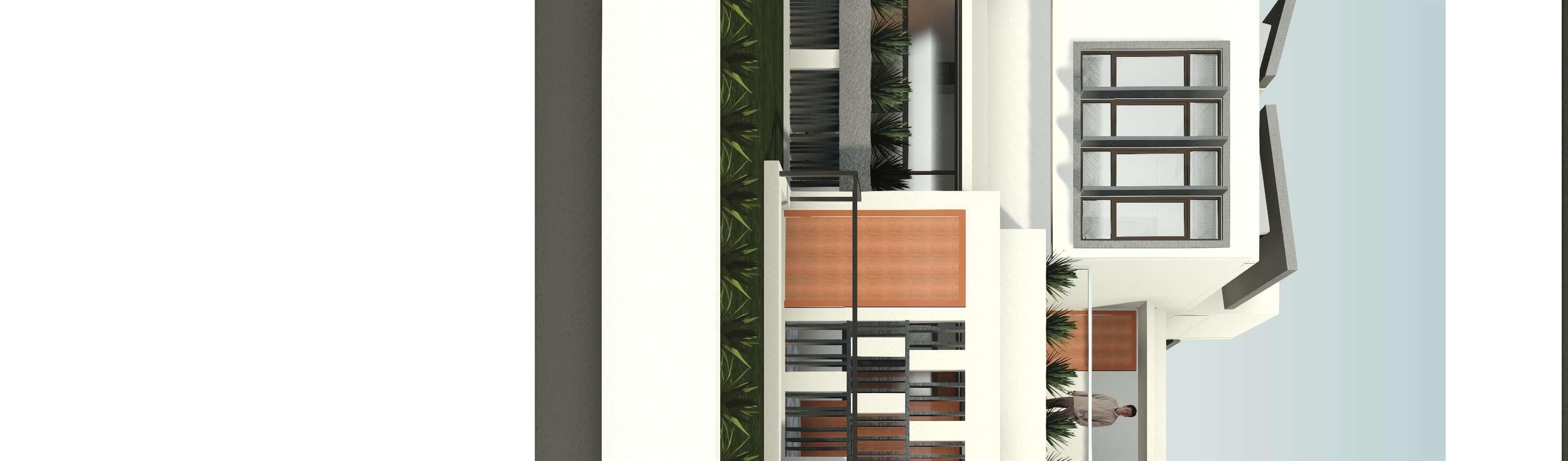


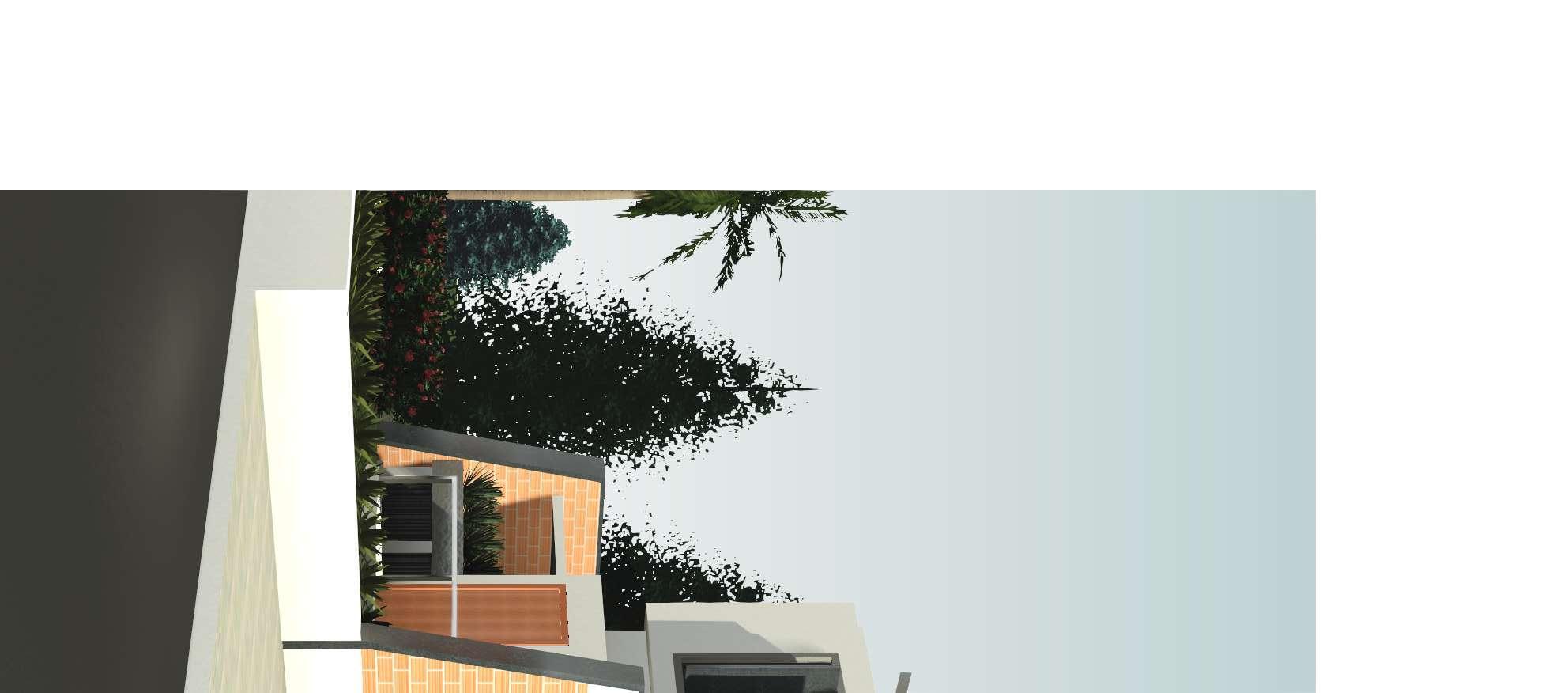

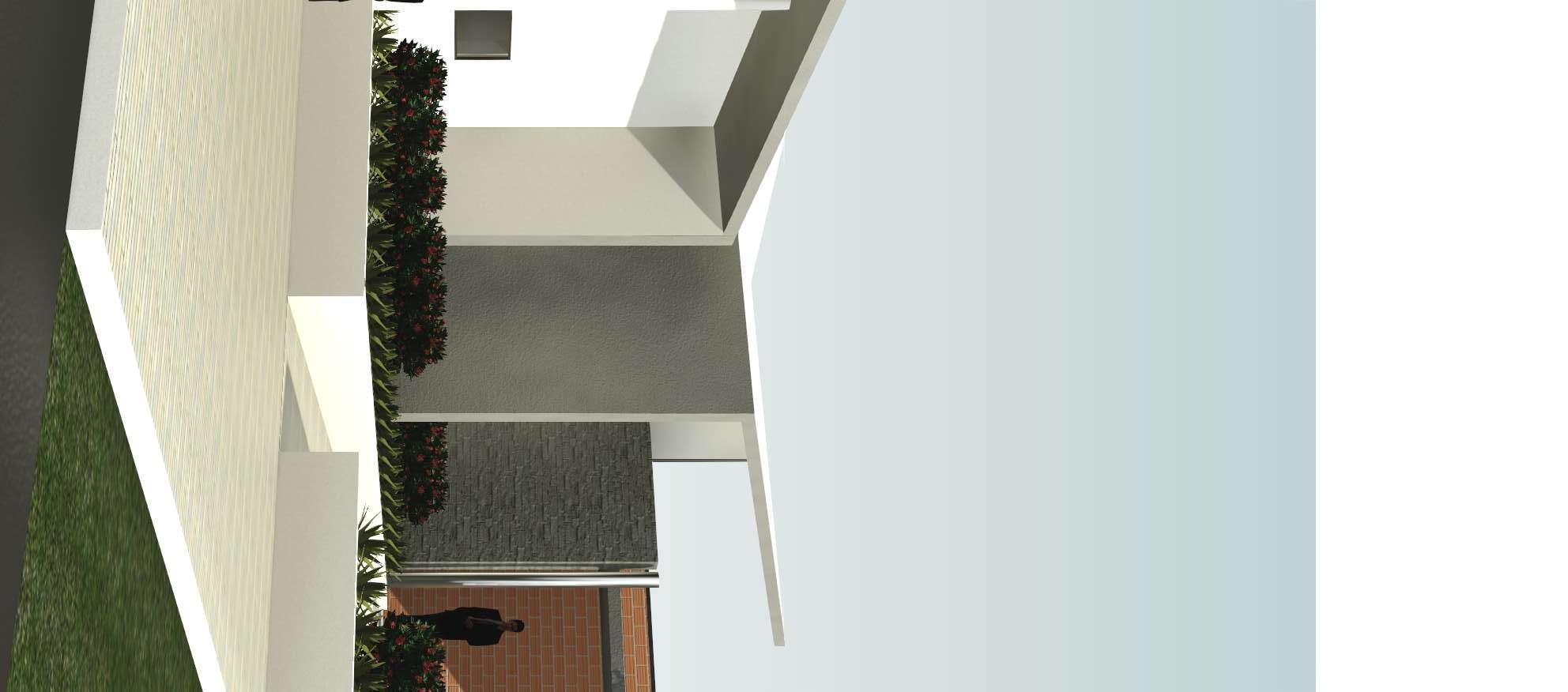
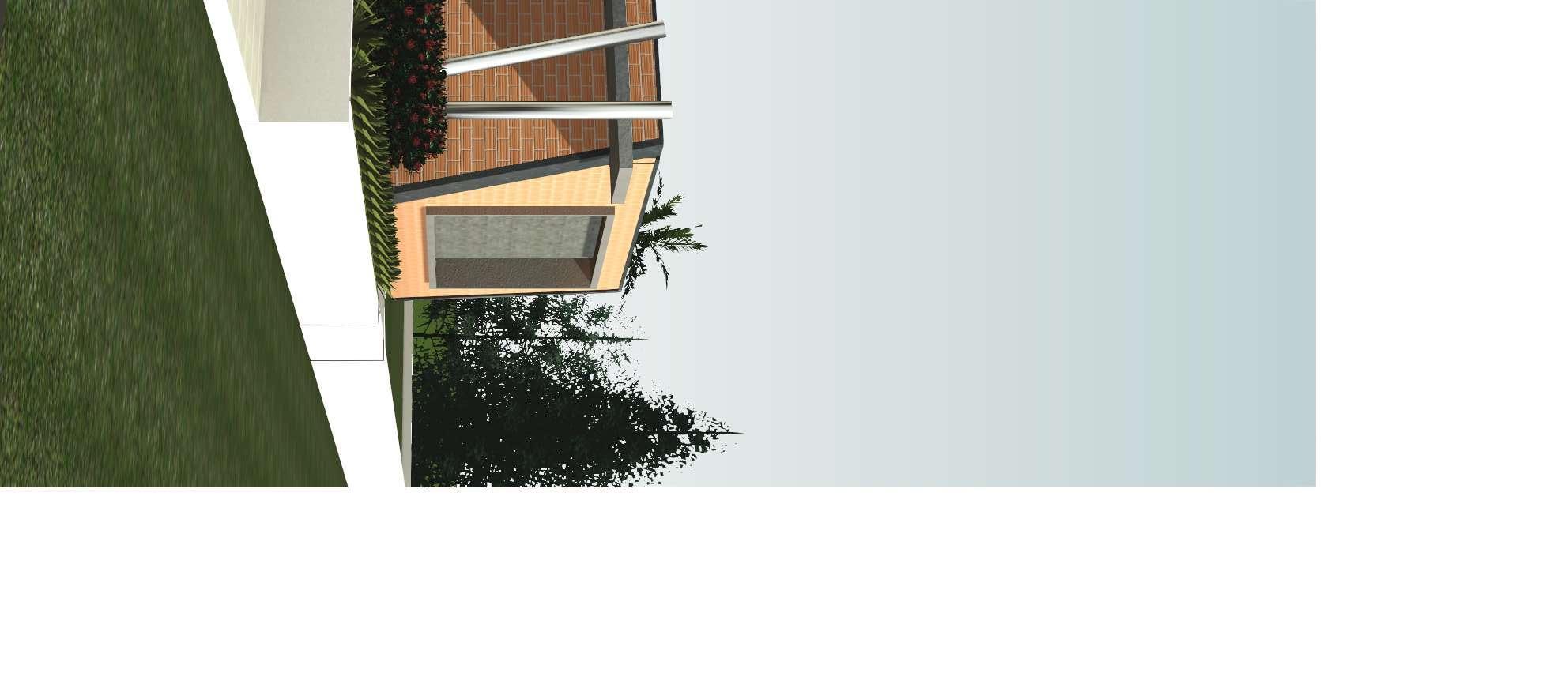
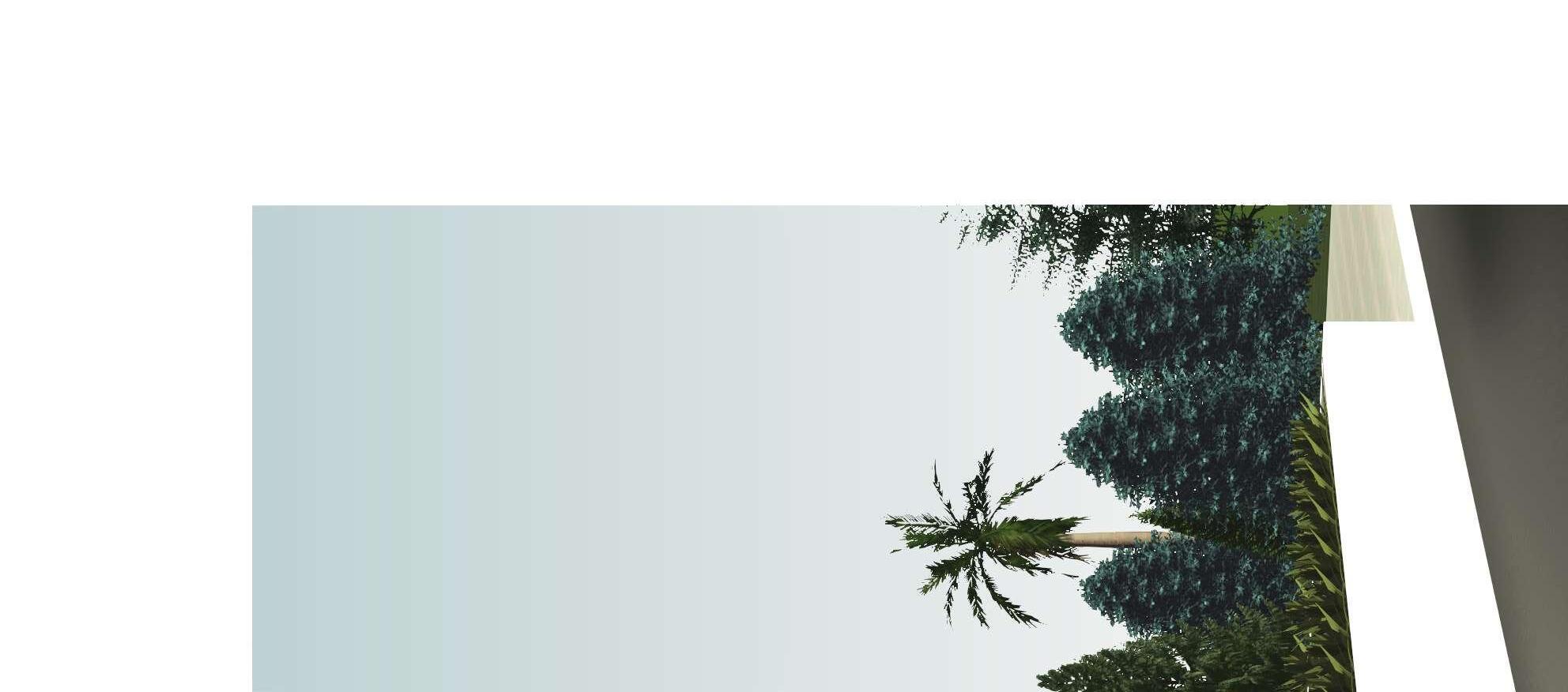
NOTES PRINTS REVISIONS DISCLAIMER PROJECT CLIENT DOCUMENT STATUS 1. Please Refer all R.C.C details in conjunction with Structural Drawing 2. All levels are given with respect to centre line of external road taken as ± 0000. 3. Framing to be as per relevant architectural & structural drawings. 5. Any discrepancy to be brought to the notice of the architect. 6. Drawings to be read & not scaled.All dimensions are in feet and inches. This document and its contents are the copyright of JEGANATH JB ARCHITECTS. Any party receiving this document does so in confidence and agrees that any of the information contained herein shall not be reproduced in whole or in part or disclosed to others without the prior written consent of the architect. JEGANATH JB ARCHITECTS Tel : 04442069848 Email : jeganathjb@gmail.com Web www.jeganathjbarchitects. carbonmade.com Address: No.1, 4th floor, Habib Complex, Durghabai Deshmukh Road, R.A.Puram, Chennai28. DRAWING TITLE DATE SCALE (A1) DRAWN BY PROJECT NO. DRAWING NO. REVISION NO. CHECKED AND APPROVED BY Ar. Jeganath.J.Balakrishnan Ar. Bharathi S NORTH Residence For Ms. Diana Mr. Xavier Maxlin Working Drawing Prespective Views 1 21/01/22 246DRT W110 1 Prespective View 1 2 Prespective View 2
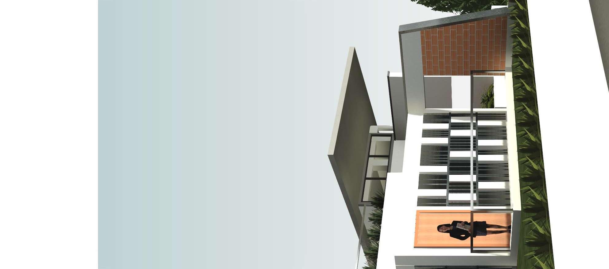

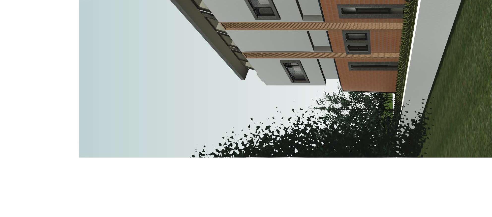


NOTES PRINTS REVISIONS DISCLAIMER PROJECT CLIENT DOCUMENT STATUS 1. Please Refer all R.C.C details in conjunction with Structural Drawing 2. All levels are given with respect to centre line of external road taken as ± 0000. 3. Framing to be as per relevant architectural & structural drawings. 5. Any discrepancy to be brought to the notice of the architect. 6. Drawings to be read & not scaled.All dimensions are in feet and inches. This document and its contents are the copyright of JEGANATH JB ARCHITECTS. Any party receiving this document does so in confidence and agrees that any of the information contained herein shall not be reproduced in whole or in part or disclosed to others without the prior written consent of the architect. JEGANATH JB ARCHITECTS Tel : 04442069848 Email : jeganathjb@gmail.com Web : www.jeganathjbarchitects. carbonmade.com Address: No.1, 4th floor, Habib Complex, Durghabai Deshmukh Road, R.A.Puram, Chennai28. DRAWING TITLE DATE SCALE (A1) DRAWN BY PROJECT NO. DRAWING NO. REVISION NO. CHECKED AND APPROVED BY Ar. Jeganath.J.Balakrishnan Ar. Bharathi S NORTH Residence For Ms. Diana Mr. Xavier Maxlin Working Drawing Prespective Views 2 21/01/22 246DRT W111 1 Prespective View 3 2 Prespective View (Structural Model)

03

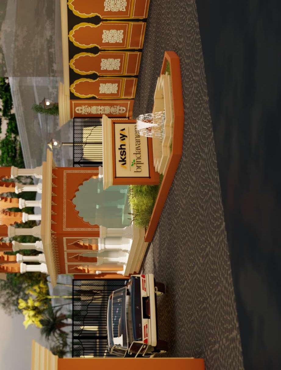
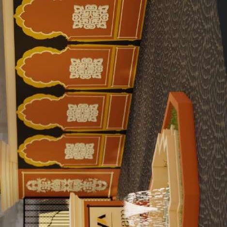
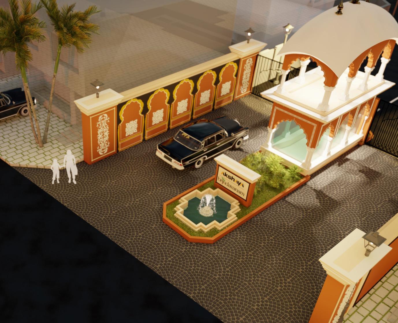
BRINDHAVANAM
PROJECT DESCRIPTION
Architect : Jeganath JB Architects
Designer : Ar Bharathi Shanmuganathan
Area : Real Estate Development & Entrance Arch Design
Year : 2022
Location : Chennai, Tamilnadu, India
Status : Under Construction

DESIGN BRIEF :
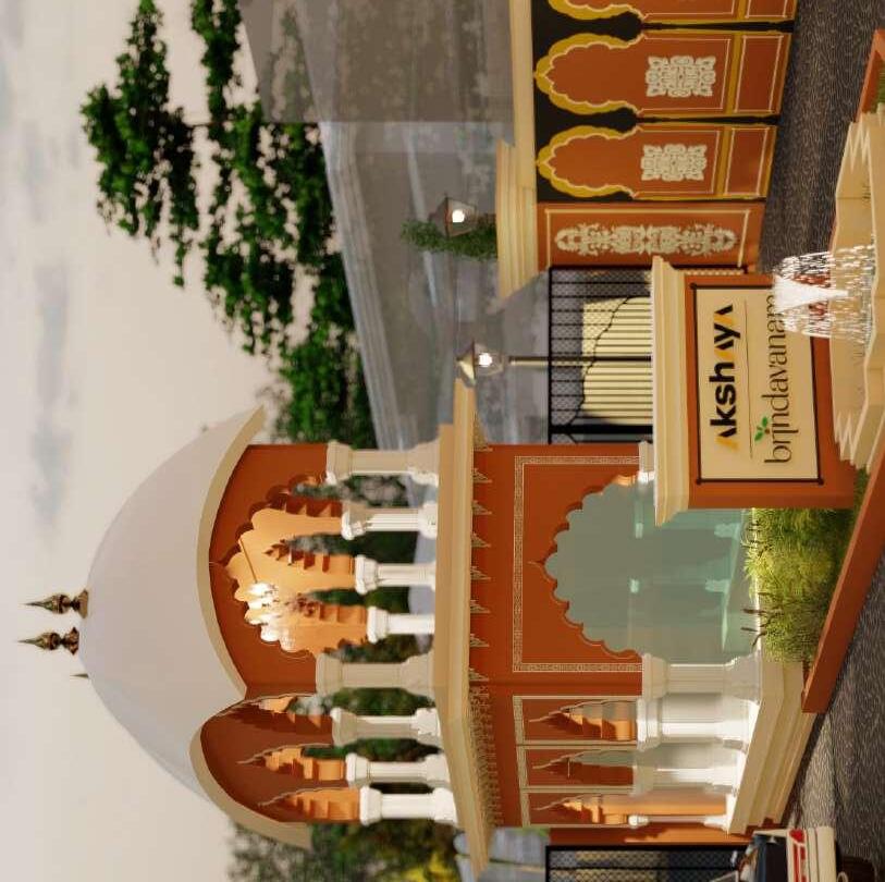
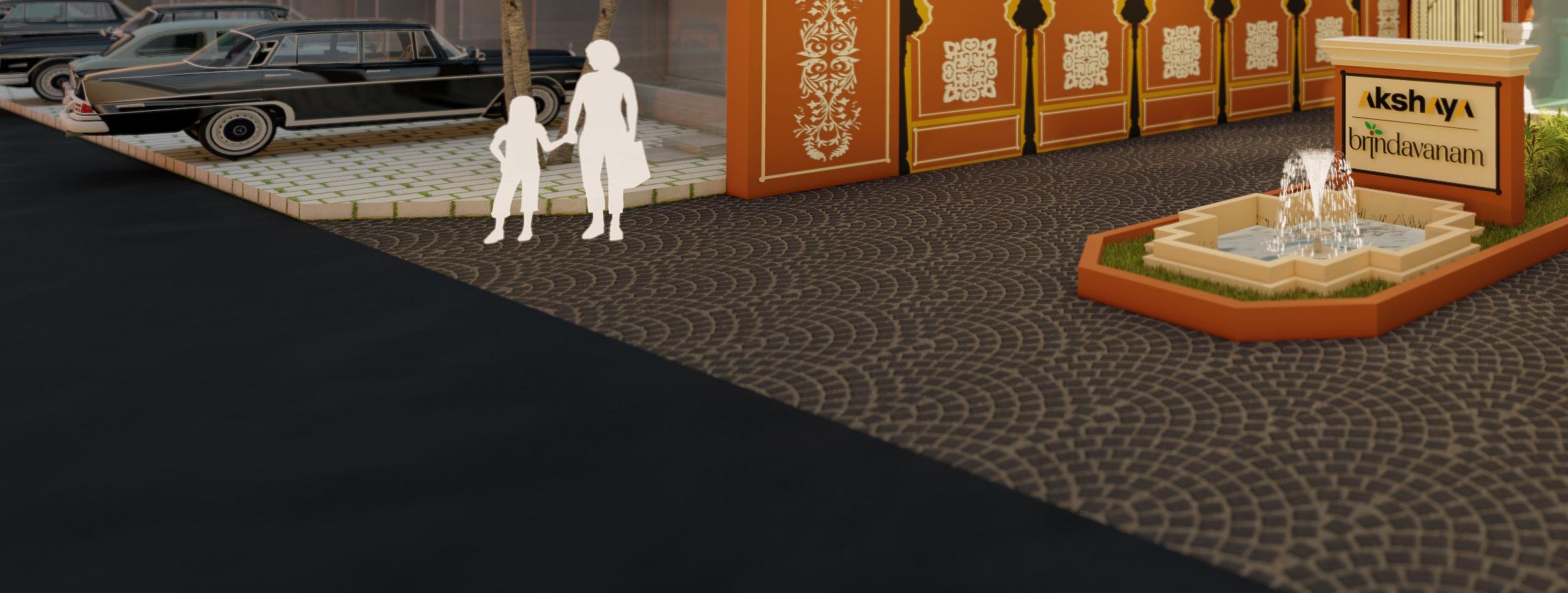
Project’s client is the Leading real estate & Property development company “AKSHAYA’’ This realestate property is located in chennai & Named as “Brindhavanam’’
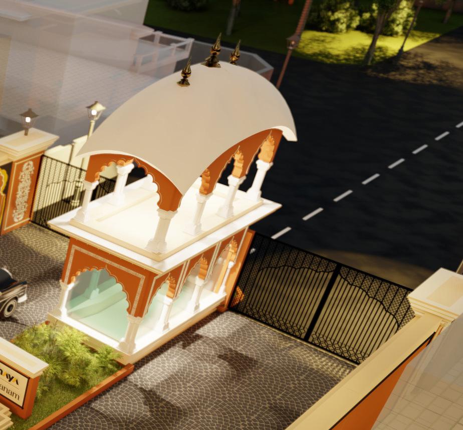
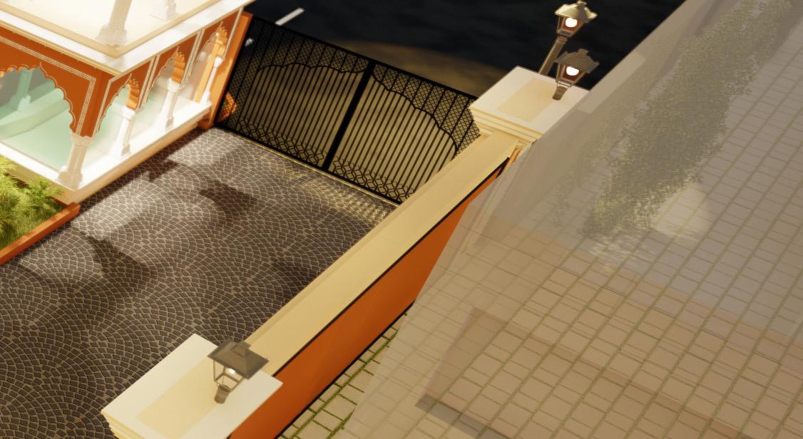
The client Requirement is to create a functional & profitable plot layout along with OSR and Public Amenities, Architectural & Welcoming entrance design, 3d (Walkthrough) visualization of the developed property for their project promotions on media.

EXPLODED AXONOMETRIC VIEW :
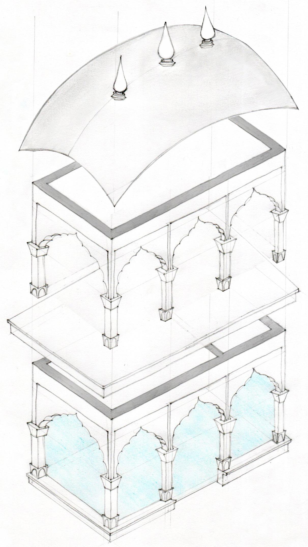
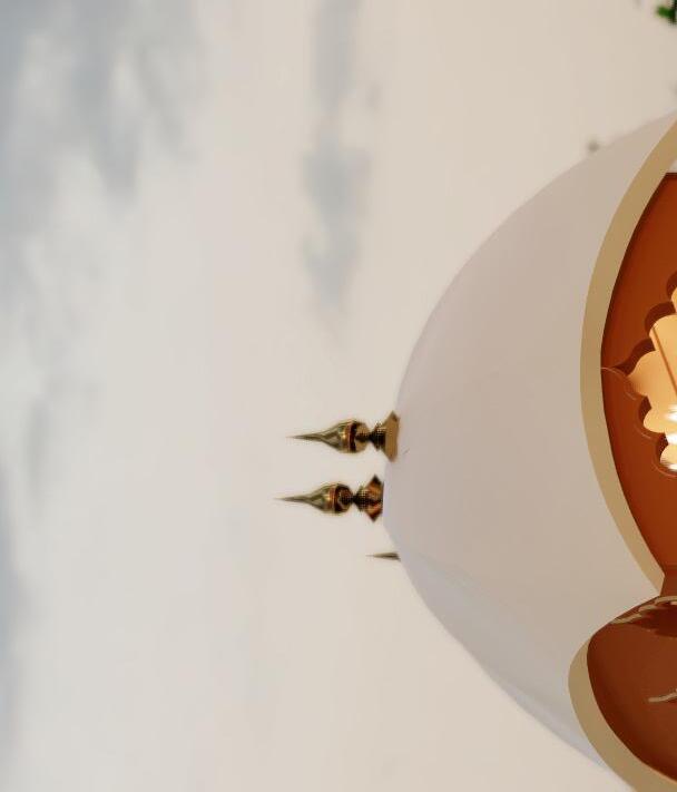
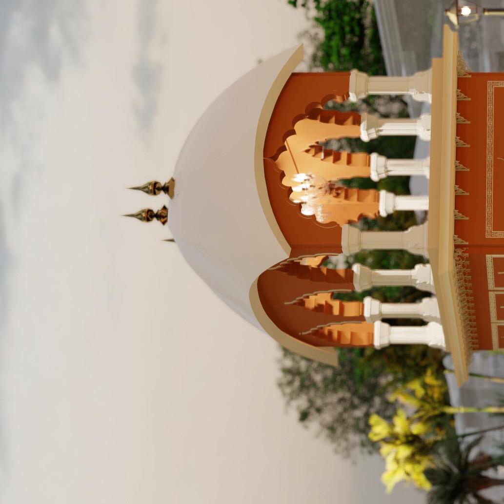
Kalasam on top of the dome. Elongated dome.
Arched entrance. Columns which supports the dome. First floor slab.
DESIGN THEORY :
ARCHITECTURE & BACKGROUND :
As the project name (Brindhaban) implies the historical city where the lord krishna spends most of his child hood according to hinduism, the design of the entrance is inspired from Kusum Sarovar monument in rajasthan which was build on memory of Krishna & Radha.
The famous Kusum Sarovar which is a sacred water reservior with historic sand monument in its backdrop. This monument was built on Rajasthani Architecture which is based on hybrid of hindu & mughal architecture influence.
DESIGN FEATURE :
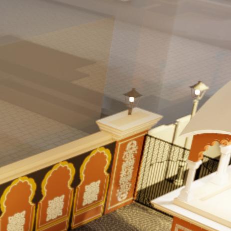
The Entrance design was evolved from Chhatri, Meaning “Tent’’ or “Umbrella’’ in hindi. These are elevated dome shaped pavillions and are visible elements of the Rajasthani Architecture, where they are the symbols of Pride & Honour
The struture acts as a pavillion with large dome supported by columns which have architectural carvings & detailings.
Glazed Facade.
Glazed entrance to the security room. Security watch cabin.
COLOUR SCHEME :
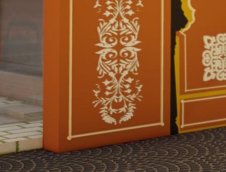
To achieve Rajasthani Architecture & to create Brindhavan feel is the basic concept of the design.
Therefore colour scheme were selected to replicate the sand stone which is used widely in construction of monuments in rajasthan. This also enhances the Feel & Aesthetic of the entrance design.
4830 2630 530 150 50 1272 845 1435 6020 1137 316 1137 367 1125 316 700 388 394 1480 3240 300 2456 350 156 115 845 1800 2796 1230 382 250 500 628 456 250 250 250 1272 R175 1772 B A SECURITY'S TOILET SECURITY CABIN FOUNTAIN FREE STANDING WALL (AKSHAYA NAME BOARD) GLASS DOOR 4830 316 1137 367 1125 367 1137 316 108 394 1627 394 2630 Ø130 Ø198 Ø198 Ø130 Ø130 Ø198 Ø198 Ø130 108 LEVEL 2 B A ROOF ABOVE 7745 150 150 400 1755 2073 743 150 150 1575 2673 1715 +3350 MM LEVEL 2 +300 MM LEVEL 1 ±0 MM ROAD LEVEL 1 FREE STANDING BRICK WALL (AKSHAYA NAME BOARD) FOUNTAIN CONCRETE VAULT ORNAMENTAL ARCH DECORATIVE KALASA IN CEMENT WOODEN BRACKETS DECORATIVE COLUMN WITH PEDESTAL CORNICE PROJECTIONS 150 150 400 1755 2073 743 150 150 1755 993 666 151 684 3050 3714 300 +3350 MM LEVEL +300 MM LEVEL 1 ±0 MM ROAD LEVEL 1 CONCRETE VAULT ORNAMENTAL ARCH DECORATIVE KALASA IN CEMENT WOODEN BRACKETS DECORATIVE COLUMN WITH PEDESTAL CORNICE PROJECTIONS +3350 MM LEVEL +300 MM LEVEL 1 ±0 MM ROAD LEVEL 1 LEVEL 1 PLAN Scale: 1:40 LEVEL 2 PLAN Scale: 1:40 SECTION A Scale: 1:40 SECTION B Scale: 1:40 HORIZONTAL ELEVATION Scale: 1:40 FRONT ELEVATION Scale: 1:40 DISCLAIMER This document and its contents are the copyright of JEGANATH JB ARCHITECTS. Any party receiving this document does so in confidence and agrees that any of the information contained herein shall not be reproduced in whole or in part or disclosed to others without the prior written consent of the architect. DOCUMENT STATUS Working Drawing PRINTS REVISIONS NOTES 1.ALL DIMENSIONS ARE IN MM. 2. THIS DRAWING IS TO BE READ IN CONJUNCTION WITH RELEVANT CONSULTANTS DRAWINGS. DISCREPANCIES IF ANY ARE TO BE BROUGHT TO THE NOTICE OF THE ARCHITECT PRIOR. AKSHAYA PVT LTD DRAWING TITLE ENTRY GUARD ROOM DETAILS A1 - 1:40 PROJECT NO. DRAWING NO. REVISION NO. DRAWN BY DATE 09-02-2022 SCALE Ar BHARATHI S 308-AK-BDP N O R T H JEGANATH JB ARCHITECTS Tel(m): 91 - 9840570026 Email jeganathjb@gmail.com Web : www.jeganathjbarchitects.carbonmade.com Address: No.6, 6th floor, Ram Swathi Towers, Durghabai Deshmukh Road, R.A.Puram, Chennai 28. W 102 REV 0 CHECKED AND APPROVED BY Ar. Jeganath.J.Balakrishnan PROJECT BRINDAHVANAM PLOT DEVELOPMENT CLIENT 4830 2630 530 150 50 1272 845 1435 6020 1137 316 1137 367 1125 316 700 388 394 1480 3240 300 2456 350 156 115 845 1800 2796 1230 382 250 500 628 456 250 250 250 1272 R175 1772 B A SECURITY'S TOILET SECURITY CABIN FOUNTAIN FREE STANDING WALL (AKSHAYA NAME BOARD) GLASS DOOR 4830 316 1137 367 1125 367 1137 316 108 394 1627 394 2630 Ø130 Ø198 Ø198 Ø130 Ø130 Ø198 Ø198 Ø130 108 LEVEL 2 B A ROOF ABOVE 7745 150 150 400 1755 2073 743 150 150 1575 2673 1715 +3350 MM LEVEL 2 +300 MM LEVEL 1 ±0 MM ROAD LEVEL 1 FREE STANDING BRICK WALL (AKSHAYA NAME BOARD) FOUNTAIN CONCRETE VAULT ORNAMENTAL ARCH DECORATIVE KALASA IN CEMENT WOODEN BRACKETS DECORATIVE COLUMN WITH PEDESTAL CORNICE PROJECTIONS 150 150 400 1755 2073 743 150 150 1755 993 666 151 684 3050 3714 300 +3350 MM LEVEL 2 +300 MM LEVEL ±0 MM ROAD LEVEL CONCRETE VAULT ORNAMENTAL ARCH DECORATIVE KALASA IN CEMENT WOODEN BRACKETS DECORATIVE COLUMN WITH PEDESTAL CORNICE PROJECTIONS +3350 MM LEVEL 2 +300 MM LEVEL ±0 MM ROAD LEVEL LEVEL 1 PLAN Scale: 1:40 LEVEL 2 PLAN Scale: 1:40 SECTION A Scale: 1:40 SECTION B Scale: 1:40 HORIZONTAL ELEVATION Scale: 1:40 FRONT ELEVATION Scale: 1:40 DISCLAIMER This document and its contents are the copyright of JEGANATH JB ARCHITECTS. Any party receiving this document does so in confidence and agrees that any of the information contained herein shall not be reproduced in whole or in part or disclosed to others without the prior written consent of the architect. DOCUMENT STATUS Working Drawing PRINTS REVISIONS NOTES 1.ALL DIMENSIONS ARE IN MM. 2. THIS DRAWING IS TO BE READ IN CONJUNCTION WITH RELEVANT CONSULTANTS DRAWINGS. DISCREPANCIES IF ANY ARE TO BE BROUGHT TO THE NOTICE OF THE ARCHITECT PRIOR. AKSHAYA PVT LTD DRAWING TITLE ENTRY GUARD ROOM DETAILS A1 1:40 PROJECT NO. DRAWING NO. REVISION NO. DRAWN BY DATE 09-02-2022 SCALE Ar BHARATHI S 308-AK-BDP N O R T H JEGANATH JB ARCHITECTS Tel(m): 91 - 9840570026 Email : jeganathjb@gmail.com Web www.jeganathjbarchitects.carbonmade.com Address: No.6, 6th floor, Ram Swathi Towers, Durghabai Deshmukh Road, R.A.Puram, Chennai - 28. W - 102 REV 0 CHECKED AND APPROVED BY Ar. Jeganath.J.Balakrishnan PROJECT BRINDAHVANAM PLOT DEVELOPMENT CLIENT 4830 2630 530 150 50 1272 845 1435 6020 1137 316 1137 367 1125 316 700 388 394 1480 3240 300 2456 350 156 115 845 1800 2796 1230 382 250 500 628 456 250 250 250 1272 R175 1772 B A SECURITY'S TOILET SECURITY CABIN FOUNTAIN FREE STANDING WALL (AKSHAYA NAME BOARD) GLASS DOOR 4830 316 1137 367 1125 367 1137 316 108 394 1627 394 2630 Ø130 Ø198 Ø198 Ø130 Ø130 Ø198 Ø198 Ø130 108 LEVEL 2 B A ROOF ABOVE 7745 150 150 400 1755 2073 743 150 150 1575 2673 1715 +3350 MM LEVEL 2 +300 MM LEVEL ±0 MM ROAD LEVEL FREE STANDING BRICK WALL (AKSHAYA NAME BOARD) FOUNTAIN CONCRETE VAULT ORNAMENTAL ARCH DECORATIVE KALASA IN CEMENT WOODEN BRACKETS DECORATIVE COLUMN WITH PEDESTAL CORNICE PROJECTIONS 150 150 400 1755 2073 743 150 150 1755 993 666 151 684 3050 3714 300 +3350 MM LEVEL +300 MM LEVEL 1 ±0 MM ROAD LEVEL 1 CONCRETE VAULT ORNAMENTAL ARCH DECORATIVE KALASA IN CEMENT WOODEN BRACKETS DECORATIVE COLUMN WITH PEDESTAL CORNICE PROJECTIONS +3350 MM LEVEL +300 MM LEVEL 1 ±0 MM ROAD LEVEL 1 LEVEL 1 PLAN Scale: 1:40 LEVEL 2 PLAN Scale: 1:40 SECTION A Scale: 1:40 SECTION B Scale: 1:40 HORIZONTAL ELEVATION Scale: 1:40 FRONT ELEVATION Scale: 1:40 DISCLAIMER This document and its contents are the copyright of JEGANATH JB ARCHITECTS. Any party receiving this document does so in confidence and agrees any of the information contained herein shall not be reproduced in whole or in part or disclosed to others without the prior written consent of the architect. DOCUMENT STATUS Working Drawing PRINTS REVISIONS NOTES 1.ALL DIMENSIONS ARE IN MM. 2. THIS DRAWING IS TO BE READ IN CONJUNCTION WITH RELEVANT CONSULTANTS DRAWINGS. DISCREPANCIES IF ANY ARE TO BE BROUGHT TO THE NOTICE OF THE ARCHITECT PRIOR. AKSHAYA PVT LTD DRAWING TITLE ENTRY GUARD ROOM DETAILS A1 - 1:40 PROJECT NO. DRAWING NO. REVISION NO. DRAWN BY DATE 09-02-2022 SCALE Ar BHARATHI S 308-AK-BDP N O R T H JEGANATH JB ARCHITECTS Tel(m): 91 9840570026 Email jeganathjb@gmail.com Web www.jeganathjbarchitects.carbonmade.com Address: No.6, 6th floor, Ram Swathi Towers, Durghabai Deshmukh Road, R.A.Puram, Chennai 28. W - 102 REV 0 CHECKED AND APPROVED BY Ar. Jeganath.J.Balakrishnan PROJECT BRINDAHVANAM PLOT DEVELOPMENT CLIENT LEVEL 1 PLAN Scale: 1:40 LEVEL 2 PLAN Scale: 1:40 Web www.jeganathjbarchitects.carbonmade.com Address: No.6, 6th floor, Ram Swathi Towers, Durghabai Deshmukh Road, R.A.Puram, Chennai 28.
SEGMENT A SEGMENT A SEGMENT B SEGMENT B SEGMENT C SEGMENT C SEGMENT D SEGMENT D SEGMENT D SEGMENT D 100.00 ENTRANCE OLD MAHABALIPURAM ROAD (O M R) TBM STONE 1 4 5 8 9 26 27 41 51 42 52 53 54 80 81 90 102 91 103 114 115 121 123 130 131 139 140 142 143 145 OSR -1 429.75 sqm OSR - 2 1449.48 sqm 12M WIDE PROPOSED ROAD 7.2M WIDE PROPOSED ROAD 12M WIDE PROPOSED ROAD 12M WIDE PROPOSED ROAD 9M WIDE PROPOSED ROAD 9M WIDE PROPOSED ROAD 9M WIDE PROPOSED ROAD 7.2M WIDE PROPOSED ROAD 7.2M WIDE PROPOSED ROAD 7.2M WIDE PROPOSED ROAD 9M WIDE PROPOSED ROAD +99.90 +99.21 +99.21 +98.87 +98.87 +98.63 +98.63 +98.48 +98.48 +97.80 +97.83 +98.25 +98.25 +97.95 +98.25 +98.25 +98.43 +98.77 99.90 M (+ 0.32) (99.58 M NGL) 99.11 M (+ 0.64) (98.47 M NGL) (98.24 M NGL) (97.97 M NGL) (97.92 M NGL) (97.81 M NGL) 98.77 M (+ 0.82) (97.95 M NGL) 98.43 M (+ 0.61) (97.82M NGL) 98.28 M (+ 0.65) (97.63 M NGL) 98.25 M (+ 0.33) (97.92 M NGL) 98.25 M (+0.36) (97.89 M NGL) 98.25 M (+0.37) (97.88 M NGL) 99.21 M (+ 0.97) 98.87 M (+ 0.90) 98.63 M (+ 0.71) 98.48 M (+ 0.67) 99.90 M (+ 1.18) (98.72 M NGL) ENTRY COMPOUND WALL SITE PLAN - FINISHED ROAD LEVELS A1 - 1:750 230 BOUNDARY WALL SECTION TYPICAL NGL OUTSIDE PLOT INSIDE HIGHER LVL 1500 450 950 100 1400 230 330 11967 11604 450 1130 1555 300 1378 300 1378 300 1378 300 1555 1130 450 182 182 3000 2989 200 2772 200 400 NGL PLOT SIDE ROAD SIDE 230 2540 230 3000 BOUNDARY WALL PLAN TYPICAL BOUNDARY WALL TYPICAL ELEVATION ENTRANCE WALL ELEVATION ENTRANCE WALL PLAN ENTRANCE WALL SECTION A1 - 1:30 A1 - 1:30 A1 - 1:30 A1 - 1:30 A1 - 1:30 A1 - 1:30 400 800 200 200 D.P.C D.P.C 300 360 360 360 360 360 360 PILE 3000MM DEPTH Sand Filling. P.C.C. 1:4:8. DISCLAIMER This document and its contents are the copyright of JEGANATH JB ARCHITECTS. Any party receiving this document does so in confidence and agrees that any of the information contained herein shall not be reproduced in whole or in part or disclosed to others without the prior written consent of the architect. DOCUMENT STATUS Working Drawing PRINTS REVISIONS NOTES 1.ALL DIMENSIONS ARE IN MM. 2. THIS DRAWING IS TO BE READ IN CONJUNCTION WITH RELEVANT CONSULTANTS DRAWINGS. DISCREPANCIES IF ANY ARE TO BE BROUGHT TO THE NOTICE OF THE ARCHITECT PRIOR. AKSHAYA PVT LTD DRAWING TITLE COMPOUND WALL DETAILS A1 1:750 PROJECT NO. DRAWING NO. REVISION NO. DRAWN BY DATE 05-02-2022 SCALE Ar BHARATHI S 308-AK-BDP N O R T H JEGANATH JB ARCHITECTS Tel(m): 91 9840570026 Email : jeganathjb@gmail.com Web www.jeganathjbarchitects.carbonmade.com Address: No.6, 6th floor, Ram Swathi Towers, Durghabai Deshmukh Road, R.A.Puram, Chennai - 28. W - 101 REV 0 CHECKED AND APPROVED BY Ar. Jeganath.J.Balakrishnan PROJECT BRINDAHVANAM PLOT DEVELOPMENT CLIENT SEGMENT A SEGMENT A SEGMENT B SEGMENT B SEGMENT C SEGMENT C SEGMENT D SEGMENT D SEGMENT D SEGMENT D 100.00 ENTRANCE OLD MAHABALIPURAM ROAD (O M R) TBM STONE 1 4 5 8 9 26 27 41 51 42 52 53 54 80 81 90 102 91 103 114 115 121 123 130 131 139 140 142 143 145 OSR -1 429.75 sqm OSR - 2 1449.48 sqm 12M WIDE PROPOSED ROAD 9M WIDE PROPOSED ROAD 7.2M WIDE PROPOSED ROAD 12M WIDE PROPOSED ROAD 12M WIDE PROPOSED ROAD 9M WIDE PROPOSED ROAD 9M WIDE PROPOSED ROAD 9M WIDE PROPOSED ROAD 7.2M WIDE PROPOSED ROAD 7.2M WIDE PROPOSED ROAD 7.2M WIDE PROPOSED ROAD 9M WIDE PROPOSED ROAD +99.90 +99.21 +99.21 +98.87 +98.87 +98.63 +98.63 +98.48 +98.48 +97.80 +97.83 +98.25 +98.25 +97.95 +98.25 +98.25 +98.43 +98.77 99.90 M (+ 0.32) (99.58 M NGL) 99.11 M (+ 0.64) (98.47 M NGL) (98.24 M NGL) (97.97 M NGL) (97.92 M NGL) (97.81 M NGL) 98.77 M (+ 0.82) (97.95 M NGL) 98.43 M (+ 0.61) (97.82M NGL) 98.28 M (+ 0.65) (97.63 M NGL) 98.25 M (+ 0.33) (97.92 M NGL) 98.25 M (+0.36) (97.89 M NGL) 98.25 M (+0.37) (97.88 M NGL) 99.21 M (+ 0.97) 98.87 M (+ 0.90) 98.63 M (+ 0.71) 98.48 M (+ 0.67) 99.90 M (+ 1.18) (98.72 M NGL) ENTRY COMPOUND WALL SITE PLAN - FINISHED ROAD LEVELS A1 - 1:750 230 BOUNDARY WALL SECTION TYPICAL NGL OUTSIDE PLOT INSIDE HIGHER LVL 1500 450 950 100 1400 230 330 11967 11604 450 1130 1555 300 1378 300 1378 300 1378 300 1555 1130 450 182 182 3000 2989 200 2772 200 400 NGL PLOT SIDE ROAD SIDE 230 2540 230 3000 BOUNDARY WALL PLAN TYPICAL BOUNDARY WALL TYPICAL ELEVATION ENTRANCE WALL ELEVATION ENTRANCE WALL PLAN ENTRANCE WALL SECTION A1 - 1:30 A1 - 1:30 A1 - 1:30 A1 - 1:30 A1 - 1:30 A1 - 1:30 400 800 200 200 D.P.C D.P.C 300 360 360 360 360 360 360 PILE 3000MM DEPTH Sand Filling. P.C.C. 1:4:8. DISCLAIMER This document and its contents are the copyright of JEGANATH JB ARCHITECTS. Any party receiving this document does so in confidence and agrees that any of the information contained herein shall not be reproduced in whole or in part or disclosed to others without the prior written consent of the architect. DOCUMENT STATUS Working Drawing PRINTS REVISIONS NOTES 1.ALL DIMENSIONS ARE IN MM. 2. THIS DRAWING IS TO BE READ IN CONJUNCTION WITH RELEVANT CONSULTANTS DRAWINGS. DISCREPANCIES IF ANY ARE TO BE BROUGHT TO THE NOTICE OF THE ARCHITECT PRIOR. AKSHAYA PVT LTD DRAWING TITLE COMPOUND WALL DETAILS A1 1:750 PROJECT NO. DRAWING NO. REVISION NO. DRAWN BY DATE 05-02-2022 SCALE Ar BHARATHI S 308-AK-BDP N O R T H JEGANATH JB ARCHITECTS Tel(m): 91 - 9840570026 Email : jeganathjb@gmail.com Web www.jeganathjbarchitects.carbonmade.com Address: No.6, 6th floor, Ram Swathi Towers, Durghabai Deshmukh Road, R.A.Puram, Chennai - 28. W - 101 REV 0 CHECKED AND APPROVED BY Ar. Jeganath.J.Balakrishnan PROJECT BRINDAHVANAM PLOT DEVELOPMENT CLIENT
100.00 ENTRANCE OLD MAHABALIPURAM ROAD (O M R) OSR -1 429.75 sqm OSR - 2 1449.48 sqm 12M WIDE PROPOSED ROAD 9M WIDE PROPOSED ROAD 7.2M WIDE PROPOSED ROAD 12M WIDE PROPOSED ROAD 12M WIDE PROPOSED ROAD 9M WIDE PROPOSED ROAD 9M WIDE PROPOSED ROAD 9M WIDE PROPOSED ROAD 9M WIDE PROPOSED ROAD 7.2M WIDE PROPOSED ROAD 7.2M WIDE PROPOSED ROAD 9M WIDE PROPOSED ROAD LANDSCAPE PLAN - SITE REFER SEPARATE DETAIL REFER SEPARATE DETAIL REFER SEPARATE DETAIL SCALE 1:750 10800 600 12000 600 12M WIDE ROAD TYPICAL SECTION 20MM THK PREMIX CARPET 210MM THICK G.S.B. 50MM THK BITUMINOUS MACADUM 225MM THK W.B.M. IN 3 LAYERS OF 75MM EACH WELL COMPACTED EARTH FILL AS PER SPECIFICATIONS AND AS REQURED 1500 8000 150W LAMP SCALE 1:50 20MM THK PREMIX CARPET 210MM THICK G.S.B. 50MM THK BITUMINOUS MACADUM 225MM THK W.B.M. IN 3 LAYERS OF 75MM EACH WELL COMPACTED EARTH FILL AS PER SPECIFICATIONS AND AS REQURED 7800 600 9000 600 9M WIDE ROAD TYPICAL SECTION 1500 8000 150W LAMP SCALE 1:50 6000 600 7200 600 7.2M WIDE ROAD TYPICAL SECTION 1500 8000 20MM THK PREMIX CARPET 210MM THICK G.S.B. 50MM THK BITUMINOUS MACADUM 225MM THK W.B.M. IN 3 LAYERS OF 75MM EACH WELL COMPACTED EARTH FILL AS PER SPECIFICATIONS AND AS REQURED 150W LAMP SCALE 1:50 JAISALMER STONE (40MM THICK) 1-30 1ST AVENUE ENGRAVE TEXT TYPICAL ELEVATION GRAFFITI 900 1200 SCALE 1:20 GRAFFITI TREES STREET LIGHT DISCLAIMER This document and its contents are the copyright of JEGANATH JB ARCHITECTS. Any party receiving this document does so in confidence and agrees that any of the information contained herein shall not be reproduced in whole or in part or disclosed to others without the prior written consent of the architect. DOCUMENT STATUS Working Drawing PRINTS REVISIONS NOTES 1.ALL DIMENSIONS ARE IN MM. 2. THIS DRAWING IS TO BE READ IN CONJUNCTION WITH RELEVANT CONSULTANTS DRAWINGS. DISCREPANCIES IF ANY ARE TO BE BROUGHT TO THE NOTICE OF THE ARCHITECT PRIOR. AKSHAYA PVT LTD DRAWING TITLE LANDSCAPE DETAILS A1 - 1:750 PROJECT NO. DRAWING NO. REVISION NO. DRAWN BY DATE 08-02-2022 SCALE Ar BHARATHI S 308-AK-BDP N O R T H JEGANATH JB ARCHITECTS Tel(m): 91 9840570026 Email jeganathjb@gmail.com Web www.jeganathjbarchitects.carbonmade.com Address: No.6, 6th floor, Ram Swathi Towers, Durghabai Deshmukh Road, R.A.Puram, Chennai 28. W 103 REV 0 CHECKED AND APPROVED BY Ar. Jeganath.J.Balakrishnan PROJECT BRINDAHVANAM PLOT DEVELOPMENT CLIENT 100.00 ENTRANCE OLD MAHABALIPURAM ROAD (O M R) OSR -1 429.75 sqm OSR - 2 1449.48 sqm 12M WIDE PROPOSED ROAD 9M WIDE PROPOSED ROAD 7.2M WIDE PROPOSED ROAD 12M WIDE PROPOSED ROAD 12M WIDE PROPOSED ROAD 9M WIDE PROPOSED ROAD 9M WIDE PROPOSED ROAD 9M WIDE PROPOSED ROAD 9M WIDE PROPOSED ROAD 7.2M WIDE PROPOSED ROAD 7.2M WIDE PROPOSED ROAD 9M WIDE PROPOSED ROAD LANDSCAPE PLAN - SITE REFER SEPARATE DETAIL REFER SEPARATE DETAIL REFER SEPARATE DETAIL SCALE 1:750 10800 600 12000 600 12M WIDE ROAD TYPICAL SECTION 20MM THK PREMIX CARPET 210MM THICK G.S.B. 50MM THK BITUMINOUS MACADUM 225MM THK W.B.M. IN 3 LAYERS OF 75MM EACH WELL COMPACTED EARTH FILL AS PER SPECIFICATIONS AND AS REQURED 1500 8000 150W LAMP SCALE 1:50 20MM THK PREMIX CARPET 210MM THICK G.S.B. 50MM THK BITUMINOUS MACADUM 225MM THK W.B.M. IN 3 LAYERS OF 75MM EACH WELL COMPACTED EARTH FILL AS PER SPECIFICATIONS AND AS REQURED 7800 600 9000 600 9M WIDE ROAD TYPICAL SECTION 1500 8000 150W LAMP SCALE 1:50 6000 600 7200 600 7.2M WIDE ROAD TYPICAL SECTION 1500 8000 20MM THK PREMIX CARPET 210MM THICK G.S.B. 50MM THK BITUMINOUS MACADUM 225MM THK W.B.M. IN 3 LAYERS OF 75MM EACH WELL COMPACTED EARTH FILL AS PER SPECIFICATIONS AND AS REQURED 150W LAMP SCALE 1:50 JAISALMER STONE (40MM THICK) 1-30 1ST AVENUE ENGRAVE TEXT TYPICAL ELEVATION GRAFFITI 900 1200 SCALE 1:20 GRAFFITI TREES STREET LIGHT DISCLAIMER This document and its contents are the copyright of JEGANATH JB ARCHITECTS. Any party receiving this document does so in confidence and agrees that any of the information contained herein shall not be reproduced in whole or in part or disclosed to others without the prior written consent of the architect. DOCUMENT STATUS Working Drawing PRINTS REVISIONS NOTES 1.ALL DIMENSIONS ARE IN MM. 2. THIS DRAWING IS TO BE READ IN CONJUNCTION WITH RELEVANT CONSULTANTS DRAWINGS. DISCREPANCIES IF ANY ARE TO BE BROUGHT TO THE NOTICE OF THE ARCHITECT PRIOR. AKSHAYA PVT LTD DRAWING TITLE LANDSCAPE DETAILS A1 1:750 PROJECT NO. DRAWING NO. REVISION NO. DRAWN BY DATE 08-02-2022 SCALE Ar BHARATHI S 308-AK-BDP N O R T H JEGANATH JB ARCHITECTS Tel(m): 91 - 9840570026 Email : jeganathjb@gmail.com Web : www.jeganathjbarchitects.carbonmade.com Address: No.6, 6th floor, Ram Swathi Towers, Durghabai Deshmukh Road, R.A.Puram, Chennai - 28. W - 103 REV 0 CHECKED AND APPROVED BY Ar. Jeganath.J.Balakrishnan PROJECT BRINDAHVANAM PLOT DEVELOPMENT CLIENT
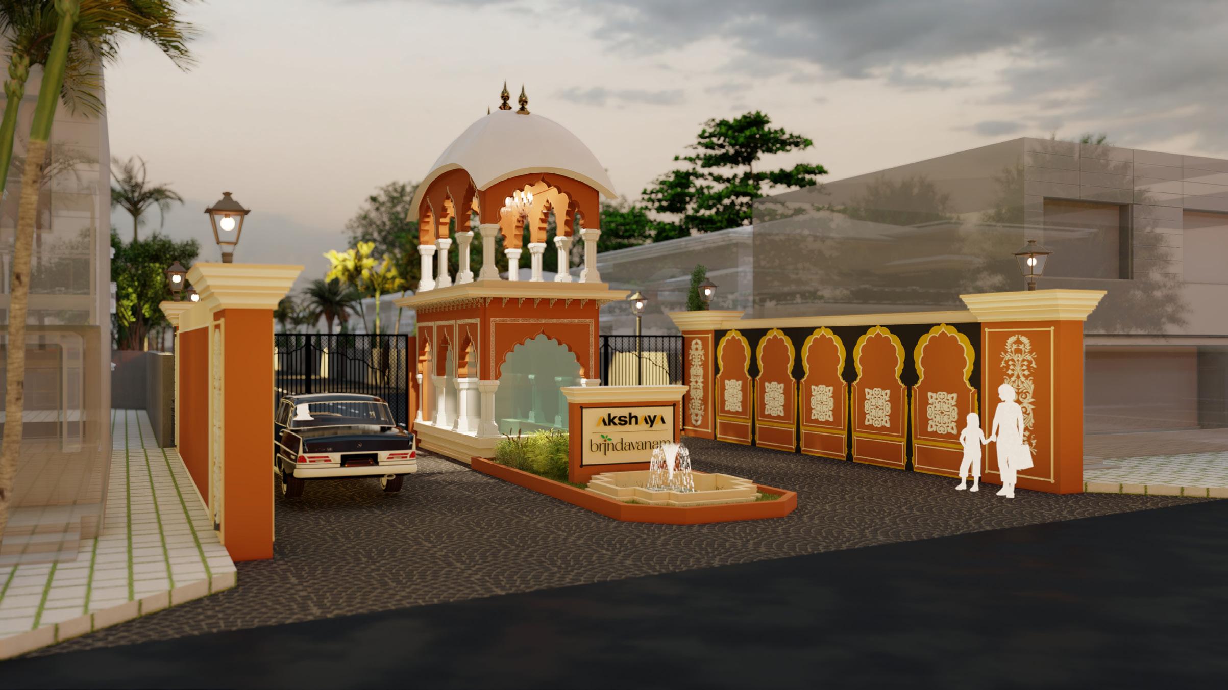
The design was inspired for the “KUSUM SAROVAR’’, the water reservior with sand stone monument built on its background on the memory of Lord Krishna and Radha. To achieve the feel and aesthetics of the monument following design features have been added to the design.
Stone block flooring near the entrance have been added to separate the typical asphalt road and to create the enhanced feel while entering the realestate property. To recreate the water reservior from the Kusum Sarovar, Water fountain have been introduced in front of the security watch cabin.
All plots on the road front are earmarked for the commercial usage, the design proposals for these commercial buildings were predecided to have a minimal architectural features on the facade without disturbing or over powering the actual entrance of the Realestate property.
The Colonnade, Arched facade, Domical roof, Kumbam and Corbell with Cornice on in between floors are the major architectural elements of the design which creates the Rajasthani Architecture and the feel of entering the actual Brindhavan city.
Provision of grand chandelier on the domical roof created the grand, sophisticated & welcoming feel to the entrance of the reastate property.
Walls near the security cabin which defines the boundary of the road and adjacent plot has architectural carvings and contrasting colour scheme. This method of treatment has been carried out to recreate the colonnade of rajasthani forts and monuments.
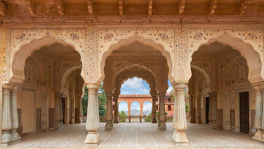
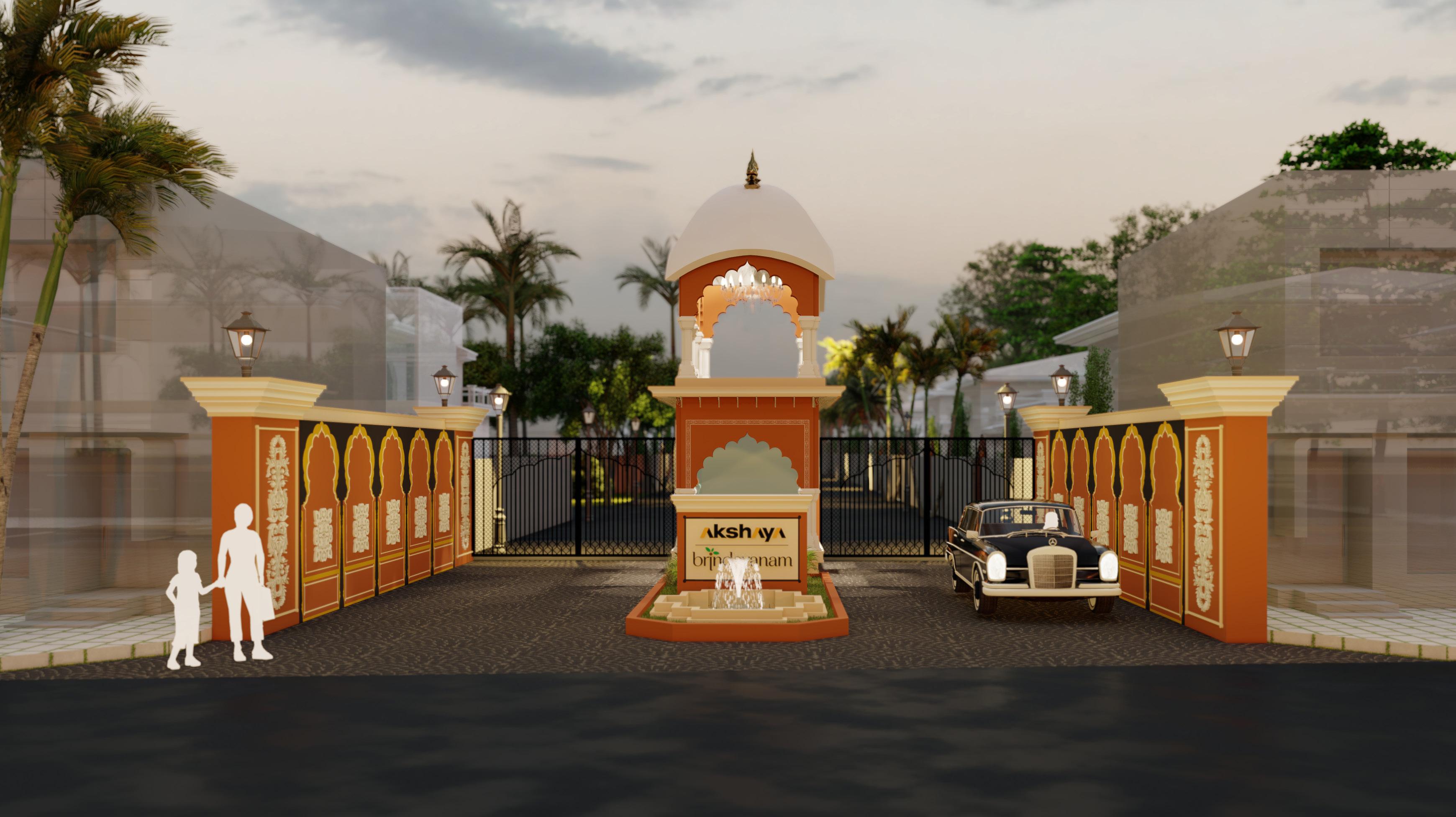
RAJASTHANI ARCHITECTURE ’’
“