

2024 AFT GUIDE NEW FEATURES


RECIPROCATING COMPRESSOR



Infinite Growth Ahead
MODELING EXCELLENCE FOR 30 YEARS
When Trey Walters quit his job and founded AFT in the basement of his Ohio home, he never imagined 30 years into the future. He was worried about the next five years, his house payment, and his three small children. Trey didn’t look for Channel Partners, they found him and before he knew it, the network grew organically and took AFT software into 115+ international markets.
In 1993 Trey simply had a lot of passion for creating a calculation tool that engineers, like himself, could use to work more efficiently and design better systems.
In 30 Years, AFT has hit a lot of milestones. Now as we close 2023, we also close another chapter. In August 2023, Trey made the decision that he was ready to relax a little and AFT was acquired by Datacor, who has deep roots in industrial refining and processes. Trey, nor any of the voices and faces you are familiar with, are going anywhere and we are all excited to see what the future holds.
Cheers to 30 years, and cheers to 30 more!
YOUR LEARNING CURVE GUIDE
Use this guide to determine the level of new feature difficulty

New users will navigate with ease

Part-time users will navigate with ease

Familiar users will navigate with ease

Fully competent users will navigate with ease

Niche industry users with advanced mitigation and analysis skills will navigate with ease
FLAGSHIP FEATURES that may be found in several applications
WORKSPACE LAYERS
IMPROVED VALVE WINDOW
4-COMPONENT SLURRY MODEL
The Workspace Layers toolset significantly enhances the model building process, providing unparalleled customization options.
Page 6


COMPRESSOR MAP
The new Valve Window now clearly distinguishes between different data sources such as User Specified, Characteristic, or Handbook, to understand the available options.
Page 8


RECIPROCATING COMPRESSOR
New four-component slurry model for the SSL module, developed by leading industry experts, captures complex slurry regimes more accurately.
Page 9


TRANSIENT CHECKPOINTS
Model centrifugal compressors more accurately by accounting for multiple curves from a non-dimensional or corrected Compressor Map. Page 10
Model single or double-acting multi-cylinder reciprocating compressors, accounting fully for all fundamental thermodynamics.
Transient Checkpoints enable you to save the state of a transient simulation at any given point and resume it later from that exact point.
11
Page 1

Learning Resources
No matter your user level with AFT software products, we have training and assistance available to help you continue your education, or tools to advance your knowledge to expert levels.
FREE LEARNING CENTER
https://bit.ly/3G2mCbh

Upcoming Webinars Webinar Library Help System Tips & Tricks
SEMINAR DATES
Check the website for the most up to date information on class types, dates, and cost.
AFT Colorado Springs Hands-on seminars are held: March • June • October
AFT Houston Hands-On Seminars are held: April • November
NEW! AFT Virtual Seminars are soon to be held on a more frequent basis.
CUSTOM TEAM TRAINING
Have a large group? Let us come to you! We will bring our detailed training seminars to your location, or AFT engineers can create a customized training that directly relates to your industry projects.

KNOW YOUR STANDARDS
FREQUENCYDEPENDENT PULSATION LIMITS


API Limitations in the Pulsation Frequency Analysis (PFA) Add-on Module. You can now check for violations graphically, and see locations where the limit is exceeded.
NOTABLE FEATURES
You can find these new and enhanced features across ALL software applications


1
Custom Junction Icons
Utilize any image as a junction icon, simply by right-clicking on the Toolbox icon for the junction, selecting Add Image, and browsing to the image file. This functionality enables you to use standard P&ID icons or custom images to visually represent your equipment.
2
Isometric Freeform Drawing
Draw on the isometric grid without forcing any particular pipe routing. The Isometric drawing tools have been enhanced by adding a new Isometric Freeform drawing mode.
3
New Annotations
New shapes, line tool, and a more advanced editing panel. New Annotation shapes and a line tool have been introduced to allow more flexible markup such as revision numbers or change requests.
4
Distinguish User & AFT Fluids
New category for user-defined fluids, making it easier to find custom entries.
5
Customize Graph
From Workspace
Did you know you can easily graph results from the Workspace by right-clicking on a Pipe or Junction? This functionality has existed for a long time, but it was previously limited to a predefined set of parameters. Now, you can specify what graph types you would like to see in these menus
6
Streamlined Design Alerts
Greatly simplified the Design Alert Manager to allow easier and faster specification of important design limits.
7
Set Workspace Print Area
Now, you can confidently print a specific section or the entire model at your desired scale, eliminating the need for trial and error.
8
Timed Recovery File
Automatically generate a backup of your model that can be used to recover unsaved work in the event of unexpected application closure.

View Your Model Your Way
Significant feature #1


WORKSPACE LAYERS
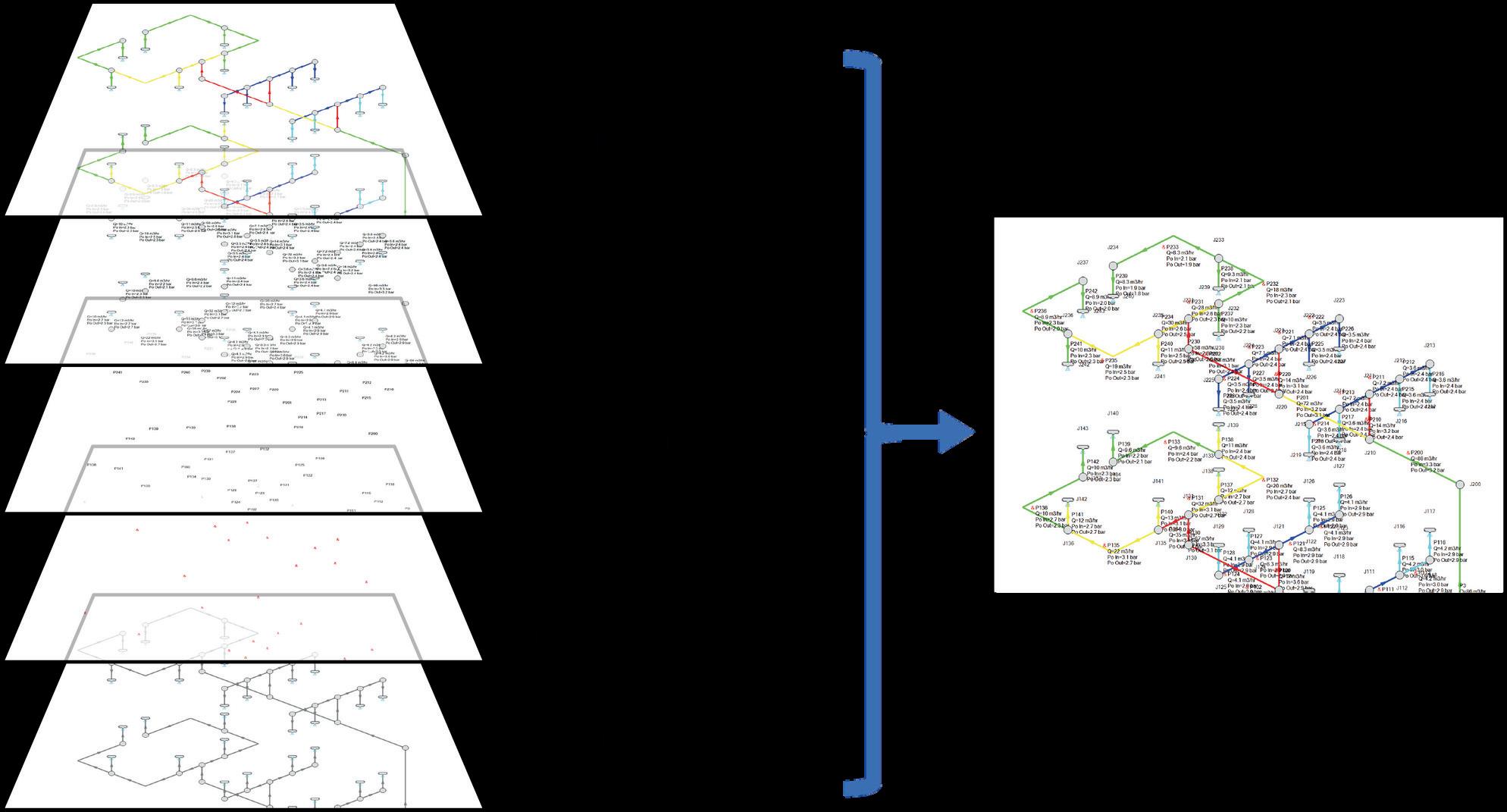
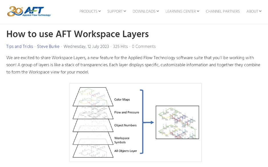
Workspace Layers are a powerful new tool for customizing and viewing model appearance, input data, and results - all in one place.

The Workspace Layers tool set significantly enhances the model building process, providing unparalleled customization options. You can easily update Pipe & Junction size, color, Display Text, visibility, and more from a centralized location on the Quick Access Panel.
Workspace Layers surpass the capabilities of the previous Visual Report feature. With Layer Setup, you now have easy control over Color Mapping and the visibility of both Input and Output parameters. Any change you make to these settings will have an immediate impact on the model’s display, providing real-time feedback.
The dynamic combination of unique Layers offers an incredibly flexible framework, allowing you to display precisely what you desire on the Workspace. You can easily toggle the visibility of individual layers on or off, and the state of all Layers can be saved to a Layer Preset for future use.


WEBINAR:
New Features - What they are and where to find them
View the new features you can expect to see in AFT Fathom 13, Arrow 10, Impulse 10, and xStream 3. Learn about the bigger changes, as well as the enhancements.
BLOG:
How to use AFT Workspace Layers
A group of layers is like a stack of transparencies. Each layer displays specific, customizable information and together they combine to form the Workspace view for your model.



WEBINAR:
What will happen when your existing Visual Reports become layers?
This webinar shows AFT users how to utilize the Layers feature which replaces the Visual Report. Results will now overlay information directly on your Workspace drawing.

Easily Define a Valve Characteristic
Significant feature #2


IMPROVED VALVE WINDOW
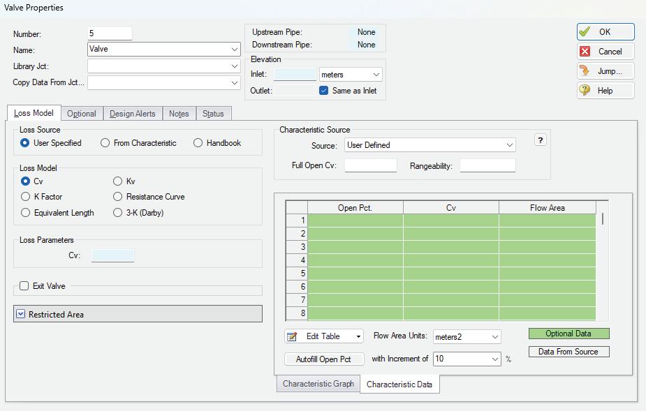
Clarifies and expands the available valve loss models, and makes it easier to define a valve characteristic, which can be critical for an accurate model.

The new Valve Window greatly enhances clarity and usability when it comes to modeling valves. The window now clearly distinguishes between different data sources such as User Specified, Characteristic, or Handbook, making it easier to understand the available options. The form has been streamlined to focus on the most essential data, providing a clear understanding of what is required to define a valve accurately.
Valve Characteristics, represented by an Open Percent vs. Flow Coefficient table, have been brought front and center. While using a Characteristic is optional, it is highly recommended as it ensures that the valve behavior aligns with real-world scenarios, particularly for valve transients. We have simplified the process of selecting a predefined Characteristic Source, which helps you obtain more accurate values in case manufacturer data is unavailable.

Capture Complex Slurry Regimes
Significant feature #3


4-COMPONENT SLURRY MODEL
The new four-component slurry model for the SSL module, developed by leading industry experts, captures complex slurry regimes more accurately.
The Four Component Slurry model introduces a division of slurry solids into four distinct groups, or components, based on the particle size distribution. Each component corresponds to a specific slurry behavior; Carrier Fluid, Pseudohomogeneous, Heterogeneous, or Fully Stratified.
Unlike simpler models that account for only one or two slurry regimes, the Four Component model greatly enhances modeling flexibility by automatically determining the effects contributed by each component regime. The model was developed by industry-leading experts and is respected for its accuracy in part because the individual components are based on well established sub models. The Four Component Slurry model offers a comprehensive and advanced approach to slurry modeling, enabling more accurate and detailed analysis of slurry behavior in various particle size distributions.

The 4-Component Slurry model offers a comprehensive and advanced approach to slurry modeling, enabling more accurate and detailed analysis of slurry behavior in various particle size distributions.

Obtain Precise Flow Curves
Significant feature #4
COMPRESSOR MAP

Model centrifugal compressors more accurately by accounting for multiple curves from a non-dimensional or corrected Compressor Map.
The Compressor Map feature allows the utilization of more precise flow curves obtained directly from the manufacturer. These curves provide a more accurate representation of the centrifugal compressor’s performance when operating away from its design conditions.
With the Compressor Map, AFT Arrow dynamically determines the closest curves to the actual operating point within the modeled system. It then performs interpolation between these curves to accurately determine the pressure ratio.
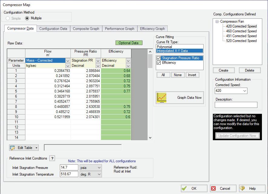
This ensures that the simulation reflects the realworld behavior of the centrifugal compressor, even when it operates outside of its originally specified conditions.

Exceptionally Powerful Simulation
Significant feature #5
RECIPROCATING COMPRESSOR
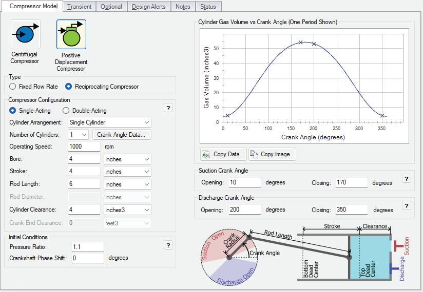
Model single or double-acting multi-cylinder reciprocating compressors, accounting fully for all fundamental thermodynamics.
Completely new in this version of AFT xStream is a fully transient reciprocating compressor model that considers the thermodynamic effects of gas being compressed or expanded in a closed chamber. Combined with the fundamental gas dynamics considered by the AFT xStream transient solver, this offers an exceptionally powerful simulation tool.
The reciprocating compressor model offers the flexibility to specify single or doubleacting compressors, with various arrangements including opposed, inline, or V configurations, accommodating up to six cylinders. The model incorporates a physical representation of the cylinder geometry and valve opening crank angles.
In combination with the PFA module improvements in this version, this enables engineers to analyze the pulsation effects of reciprocating compressor systems with greater precision and confidence.


Re-run the Entire Simulation? No Need.
Significant feature #6

TRANSIENT CHECKPOINTS
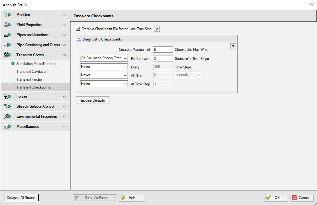
Extend the length of an existing transient run without the need to re-run the entire simulation, or stop and continue a run from other points in the simulation.
Transient Checkpoints enable you to save the state of a transient simulation at any given point and resume it later from that exact point. This functionality proves particularly useful in scenarios where you need to pause a simulation temporarily to provide access to another user or when unexpected interruptions, such as system updates, occur during the simulation.
This feature also allows for the extension of a transient run. If you have ever experienced the frustration of waiting for results only to realize that you should have run the simulation for a slightly longer duration, this feature provides a solution.
Instead of rerunning the entire simulation, you can simply extend an existing run by leveraging the automatically created Transient Checkpoints.
Questions? Use the Documentation Help System
Discover AFT’s central location for all your software support needs. Find the most recent documentation for specific products. Previous version documentation can be found here as well.


Full list of new features
AFT Fathom™ 13
NOTABLE FEATURES
• Custom Junction Icons - Use your own images.
• Isometric Freeform Drawing - Draw without forcing any particular pipe routing.
• New Annotations - Use shapes and tools to allow flexible markup such as revision numbers or change requests.
• Set Workspace Print Area - Show printing page borders on the workspace and customize the printing area.
• Customize Graph From Workspace OptionsCustom selection of any graph parameter on the Workspace.
MODELING ADDITIONS & IMPROVEMENTS
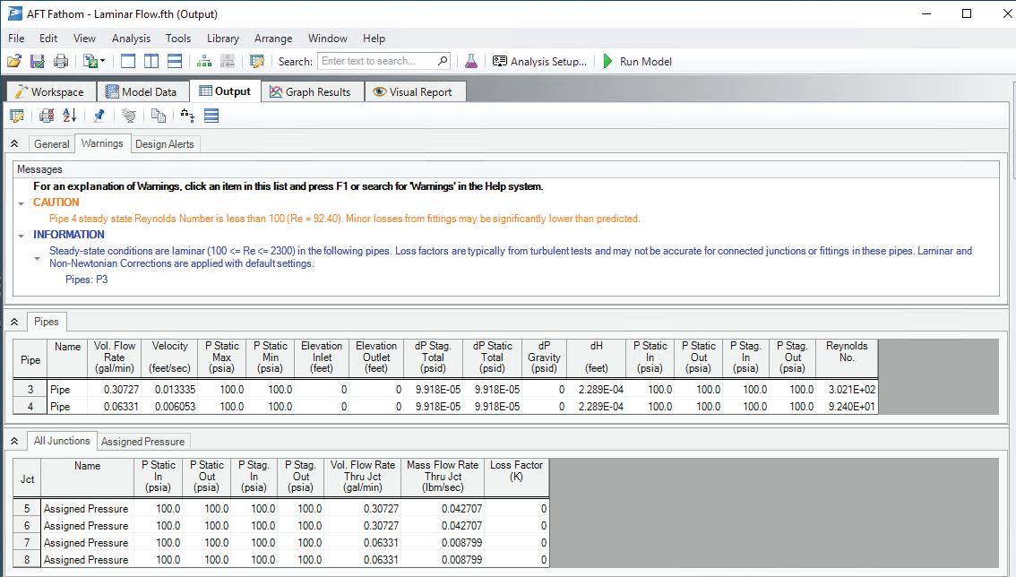
• Laminar Corrections Improvements - Laminar corrections are now off by default, messages indicate if they were applied or are recommend, and output parameters indicate the correction strength.
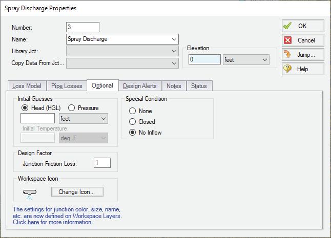
• Prevent Backflow at Sprays - New "No Inflow" Special Condition for SprayJunctions.
• Zero-Length Connector Improvements - Now behave like standard pipes, including selection and graphing tools.
• Distinguish User and AFT Fluids - Easily find custom entries.
IMPROVED IMPORTING
• Import Bend r/D - Import PCF bends with appropriate r/D
• Import Speed Increase - Import up to 10x faster
• Better Defaults and Display for Imported Models
• Improved Import of Pipe Material Links
• Display CAESAR II Node Names as junction names.
BEHIND THE SCENES IMPROVEMENTS
• Graphing Optimizations - Significant improvements to backend graphing code, to provide additional stability now and more capabilities in the future.
• eLicense Access Improvements - Improved security and the release of license seats not in use.
• Output Improvements - Improvements to backend output code provides additional stability.
• Timed Recovery File - Automatically generate a backup of your model to recover unsaved work.
OUTPUT PARAMETERS & MESSAGES
• Pump RPM Output Parameter - Report speed in RPM, in addition to percent.
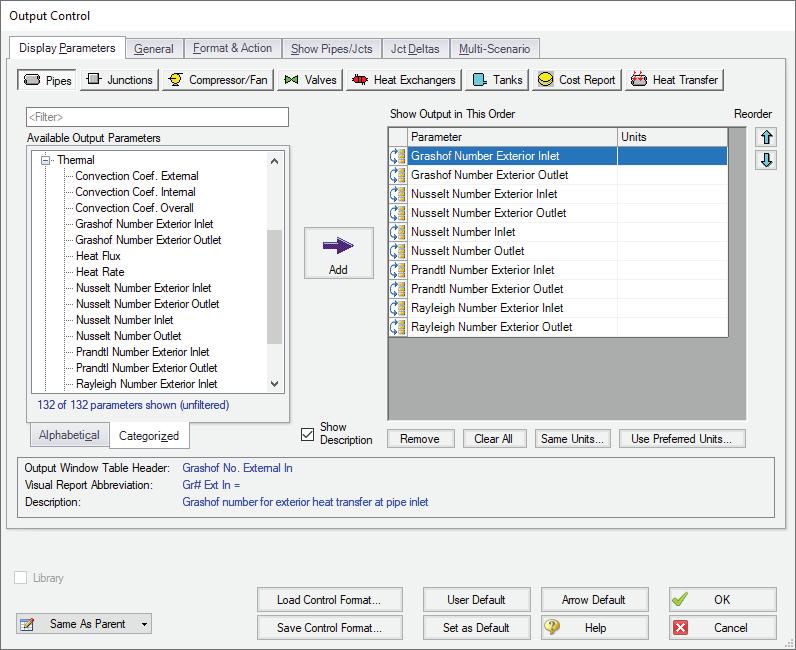
• Dimensionless Heat Transfer Output Parameters - Grashof, Nusselt, Prandtl, and Rayleigh Numbers
• Deep Laminar Caution - Simple loss models do not account for exceptionally laminar flow, this new message provides a caution if you enter this range.
• POR/AOR in Pump Summary - Shows the values for Preferred and Allowed Operating Ranges.
• Events Messages in New Format - Events now show in a clean, collapsible format similar to Warnings.
• XTS Module Tank Overflow and Drain Warnings - Indicate if a Tank has overflowed or drained.
AFT Fathom 12 AFT Fathom 13
The Workspace Layers toolset significantly enhances the modeling process. Easily update Pipe & Junction size, color, Display Text, visibility, and more from a centralized location

The new Valve Window now clearly distinguishes between different data sources such as User Specified, Characteristic, or Handbook, to understand the available options
Utilize any image as a junction icon, simply by right-clicking on the Toolbox icon
New four-component slurry model for the SSL module, developed by leading industry experts, captures complex slurry regimes more accurately
The Design Alert Manager has been reorganized to improve the process of creating and applying user-defined alerts
New Annotation shapes and a line tool allow more flexible markup such as revision numbers or change requests
Draw on the isometric grid without forcing any particular pipe routing with Isometric Freeform drawing mode
Visually analyze alternatives with Multi-Scenario Graphing, comparing profile graphs from multiple scenarios on a single plot
The Library Manager (previously the Database Manager) has been completely revised and now offers a consolidated way to use and customize libraries of fluids, pipe materials, junctions, etc.
Use the NEW online Help System for centralized documentation and examples from your browser
Streamline your setup from the new Analysis Setup menu, a user-friendly workflow condensing multiple windows into 1
Convert Shear Rheometer data for Power Law and Bingham Plastic viscosity models with a helpful visual guide
Apply the Herschel-Bulkley viscosity model for shear thinning or thickening fluids with a yield stress
Warnings, errors and Design Alerts shown in the Output are now color coded and organized in a prioritized list for quick review
AFT Fathom 11
Multi-Scenario Comparison: Data can be compared between multiple scenarios to show changes made
Cross-plot Pump vs. System curves across multiple operating scenarios
Multi-level undo and redo on the Workspace
All Summary Output parameters can now be displayed on the Visual Report
Double-click on a junction on the Toolbox to add multiple to the Workspace (similar to pipes)
Convert intermediate elevations to new pipes and branches
Can now save ‘design alerts’ and load from a file


Unlike simpler models that account for only one or two slurry regimes, the 4-Component model automatically determines the effects contributed by each component regime. The model divides slurry solids into four distinct groups based on the particle size distribution.

Laminar Corrections Improvements 4-Component Slurry Model
Laminar corrections are now off by default. Messages indicate if they were applied or are recommend, and output parameters indicate the correction strength.

Prevent Backflow at Sprays
New “No Inflow” Special Condition for Spray Junctions.
XTS Module Tank Overflow and Drain Warnings
New messages to clearly indicate if a Tank has overflowed or drained during the transient.



Full list of new features
AFT Arrow™ 10
NOTABLE FEATURES
• Custom Junction Icons - Use your own images.
• Isometric Freeform Drawing - Draw without forcing any particular pipe routing.
• New Annotations - Use shapes and tools to allow flexible markup such as revision numbers or change requests.
• Set Workspace Print Area - Show printing page borders on the workspace and customize the printing area.
• Customize Graph From Workspace OptionsCustom selection of any graph parameter on the Workspace.
MODELING ADDITIONS & IMPROVEMENTS
• Prevent Backflow at Sprays - New “No Inflow” Special Condition for Spray Junctions.
• Zero-Length Connector Improvements - Now behave like standard pipes, including selection and graphing tools.
• Distinguish User and AFT Fluids - Easily find custom entries.
IMPROVED IMPORTING
• Import Bend r/D - Import PCF bends with appropriate r/D
• Import Speed Increase - Import up to 10x faster
• Better Defaults and Display for Imported Models
• Improved Import of Pipe Material Links
• Display CAESAR II Node Names as junction names.
BEHIND THE SCENES IMPROVEMENTS
• Graphing Optimizations - Significant improvements to backend graphing code, to provide additional stability now and more capabilities in the future.
• eLicense Access Improvements - Improved security and the release of license seats not in use.
• Output Improvements - Improvements to backend output code provides additional stability.
• Timed Recovery File - Automatically generate a backup of your model to recover unsaved work.
OUTPUT PARAMETERS & MESSAGES
• Compressor RPM Output Parameter - Report speed in RPM, in addition to percent.
• Dimensionless Heat Transfer Output Parameters - Grashof, Nusselt, Prandtl, and Rayleigh Numbers
• Valve xT Output Parameter - Report and graph
• Estimated xT Output Parameter as used in the solver for valve loss models that do not use Cv/xT.
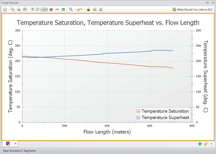
• Profile Graphs for Temperature Saturation and Temperature Superheat - Graph saturation temperature and temperature above saturation (superheat).
• Laminar Caution - If junction flow is in a laminar range
• POR/AOR in Compressor Summary
• Events Messages in New Format - Now shown in a clean, collapsible format similar to Warnings.
The Workspace Layers toolset significantly enhances the model building process. Easily update Pipe & Junction size, color, Display Text, visibility, and more from a centralized location
The new Valve Window now clearly distinguishes between different data sources such as User Specified, Characteristic, or Handbook, to understand the available options
Model centrifugal compressors more accurately by accounting for multiple curves from a non-dimensional or corrected Compressor Map
Estimate junction Sound Power Level according to Energy Institute Guidelines
The Design Alert Manager has been reorganized to improve the process of creating and applying user-defined alerts
Draw on the isometric grid without forcing any particular pipe routing with Isometric Freeform drawing mode
New Annotation shapes and a line tool allow more flexible markup such as revision numbers or change requests
Streamline your setup from the new Analysis Setup menu, a userfriendly workflow condensing multiple model-wide specification windows into 1
Visually analyze alternatives with Multi-Scenario Graphing to compare profile graphs and transient plots (XTS) from multiple scenarios on a single plot
The brand new Extended Time Simulation (XTS) Add-on Module models dynamic system behavior and how critical system parameters vary over time
Warnings, errors and Design Alerts shown in the Output are now color coded and organized in a prioritized list for quick review
The Library Manager (previously the Database Manager) has been completely revised and now offers a consolidated way to use and customize libraries of fluids, pipe materials, junctions, etc.
Use the NEW online Help System for centralized documentation and examples from your browser
Apply the Soave-RedlichKwong and the Peng-Robinson equations of state as additional methods to model your fluid
Multi-Scenario
Comparison: Data can be compared between multiple scenarios to show changes made

Compression ratio can be used to define the compressor performance
Multi-level undo and redo on the Workspace
All Summary Output parameters can now be displayed on the Visual Report
Improved intelligence on when a model needs to be saved to preserve the output
New and updated themes
Improved model loading speed

Profile Graphs for Temperature

Saturation and Temperature Superheat
Graph saturation temperature and temperature above saturation (superheat) along flow paths.
Dimensionless Heat Transfer Output Parameters
Grashof, Nusselt, Prandtl, and Rayleigh Numbers have been added as Output parameters.

Calculate Sound Power Levels

Estimate junction Sound Power Level according to Energy Institute Guidelines.
A new output parameter has been added for Sound Power Level, as calculated by the Energy Institute Guidelines for the Avoidance of Vibration Induced Fatigue Failure in Process Pipework.
Sound Power Level is a function of pressure drop across inline devices, and serves as an initial calculation step to assess the presence of Acoustically Induced Vibration (AIV) issues in your system.
If the calculated Sound Power Level exceeds a predefined acceptable value, a warning is issued to the user, and
the Energy Institute Guideline indicate further calculation should be done to determine Likelihood of Failure.
Sound Power Level can be calculated for the following junction types:
• Valve (Inline)
• Orifice (Inline)
• Bend
• Area Change
• Check Valve
• Control Valve
• Venturi
• Screen
• Relief Valve (Inline)
• General Component


Full list of new features
AFT Impulse™ 10
NOTABLE FEATURES
• Counterweight Check Valve - Force Balance Swing Check now allows the inclusion of a counterweight and lever arm.
• Four-Component Slurries - Captures complex slurry regimes more accurately.
• Custom Junction Icons - Use your images.
• Isometric Freeform Drawing - Draw without forcing any particular pipe routing.
• New Annotations - Use shapes and tools to allow flexible markup such as revision numbers or change requests.
• Set Workspace Print Area - Show printing page borders on the workspace and customize the printing area.
• Customize Graph From Workspace Options
ADDITIONS & IMPROVEMENTS
• Laminar Corrections Improvements - Now off by default, messages indicate if they were applied or are recommend, and output parameters indicate the correction strength.
• Zero-Length Connector Improvements - Now behave like standard pipes.
• Distinguish User and AFT Fluids - Easily find custom entries.
• Control Valve Fully Open Cannot Regain Control - Keeps the control valve in a lockedopen position during transients.
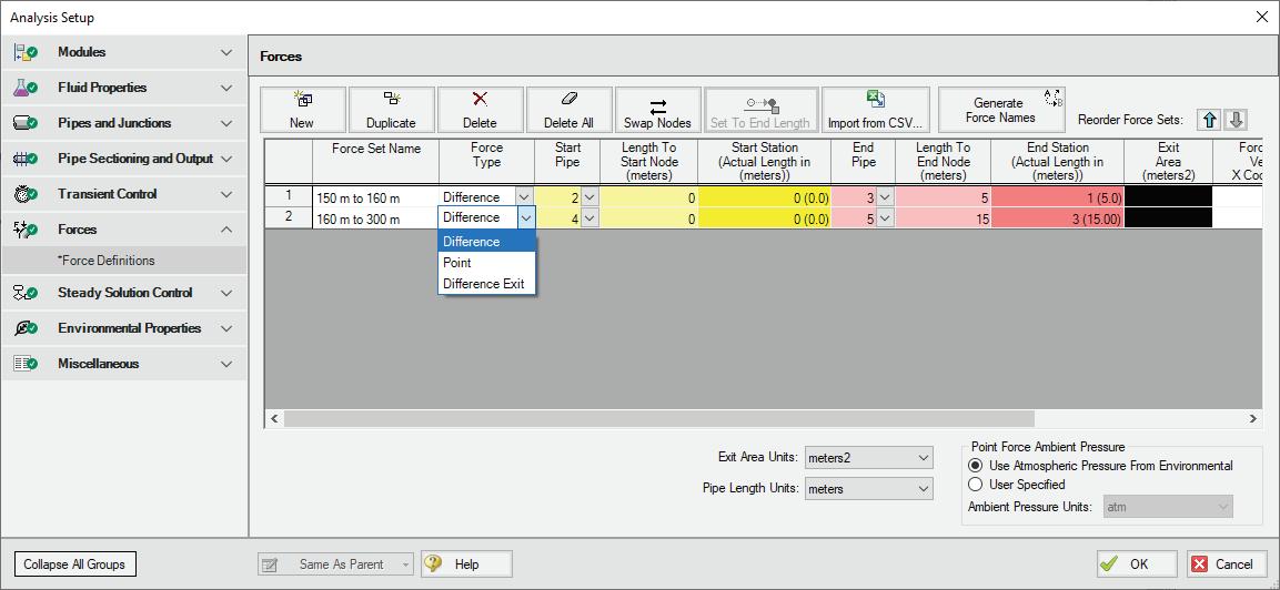
• Simpler Force Definitions - Difference forces spanning more than 2 pipes no longer require the definition of a group.
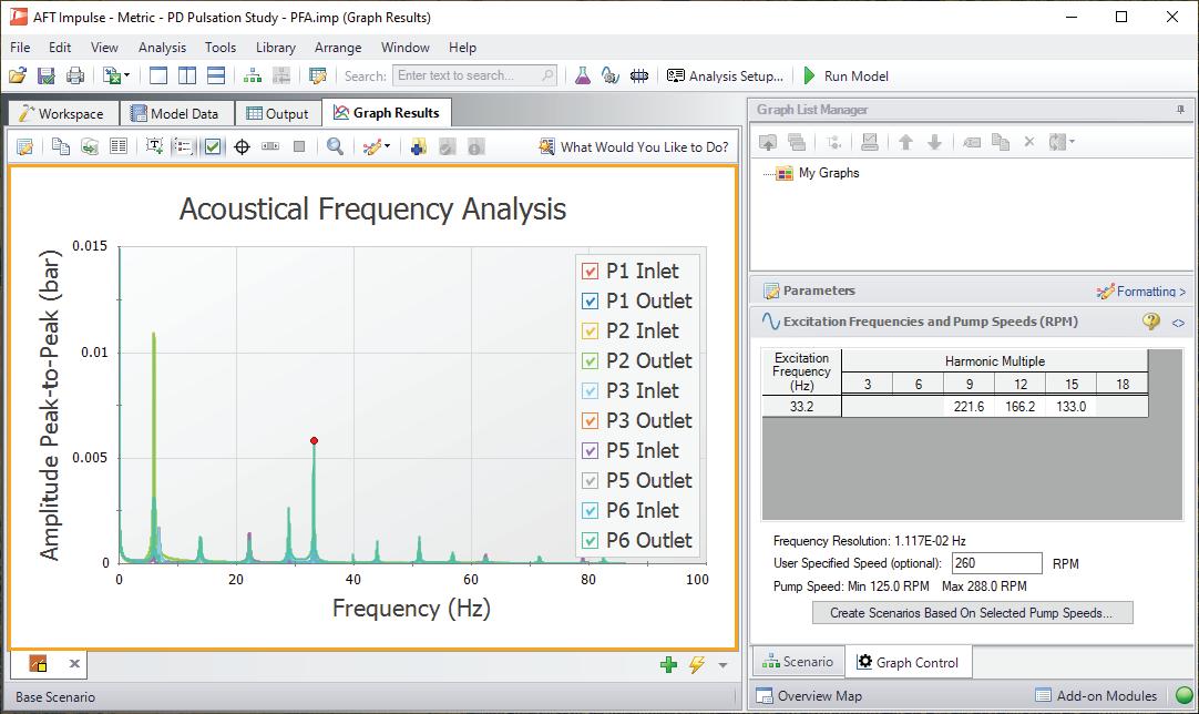
• Specify RPM to Evaluate Pulsation Levels for, instead of only evaluated worst-case frequencies.
• API 674 Limitations in PFA Module - You can now check for violations graphically.
IMPROVED IMPORTING
• Import Bend r/D - Import with appropriate r/D
• Import Speed Increase - Import up to 10x faster
• Better Defaults and Display for Imported Models
• Improved Import of Pipe Material Links
• Display CAESAR II Node Names as junction names.
BEHIND THE SCENES IMPROVEMENTS
• Graphing Optimizations - Provides additional stability now and more capabilities in the future.
• eLicense Access Improvements - Improved security and the release of seats not in use.
• Output Improvements - Improvements to backend output code provides additional stability.
• Timed Recovery File - Automatically generate a backup of your model to recover unsaved work.
OUTPUT PARAMETERS & MESSAGES
• Pump RPM Output Parameter - Report speed in RPM, in addition to percent.
• Vapor Volume Percent Output ParameterReport percentage + physical vapor volume.
• Deep Laminar Caution - Provides a caution if you enter exceptionally laminar flow.
• POR/AOR in Pump Summary - Shows the values for Preferred and Allowed Operating Ranges.
• Events Messages in New Format - Now show in a collapsible format similar to Warnings.
• Tank Overflow and Drain Warnings - Indicates if the Tank overflowed or drained during the transient.
AFT Impulse 10 AFT Impulse 9 AFT Impulse 8
The Workspace Layers toolset significantly enhances the model building process. Easily update Pipe & Junction size, color, Display Text, visibility, and more from a centralized location
The new Valve Window now clearly distinguishes between different data sources such as User Specified, Characteristic, or Handbook, to understand the available options
Retain Partial Transient Output to access and analyze the results up to the point where the simulation was interrupted
New four-component slurry model for the SSL module captures complex slurry regimes more accurately
The Design Alert Manager has been reorganized to improve the process of creating and applying user-defined alerts
Transient Checkpoints enable you to save the state of a transient simulation at any given point and resume it later from that exact point
Draw on the isometric grid without forcing any particular pipe routing
Streamline your setup from the new Analysis Setup menu, a user-friendly workflow condensing multiple model-wide specification windows into 1
The Library Manager (previously the Database Manager) has been completely revised and now offers a consolidated way to use and customize libraries of fluids, pipe materials, junctions, etc.
Use the NEW online Help System for centralized documentation and examples from your browser
No more limitations on pipe sectioning and time steps which allows more complete analysis using multi-scenario graphing
Elbows, Orifices, Venturis and Screens have been added to match AFT Fathom and aide in building models
Apply the Herschel-Bulkley viscosity model for shear thinning or thickening fluids with a yield stress
Warnings, errors and Design Alerts shown in the Output are now color coded and organized in a prioritized list for quick review
Multi-Scenario Comparison: Data can be compared between multiple scenarios to show changes made

Multi-scenario graphing allows easy comparison of results
Multi-level undo and redo on the Workspace
No more limitations on pipe sectioning and time steps which allows more complete analysis using multi-scenario graphing
New capability to model unsteady friction
New pump four-quadrant curves added
Forces can be shown on the Visual Report

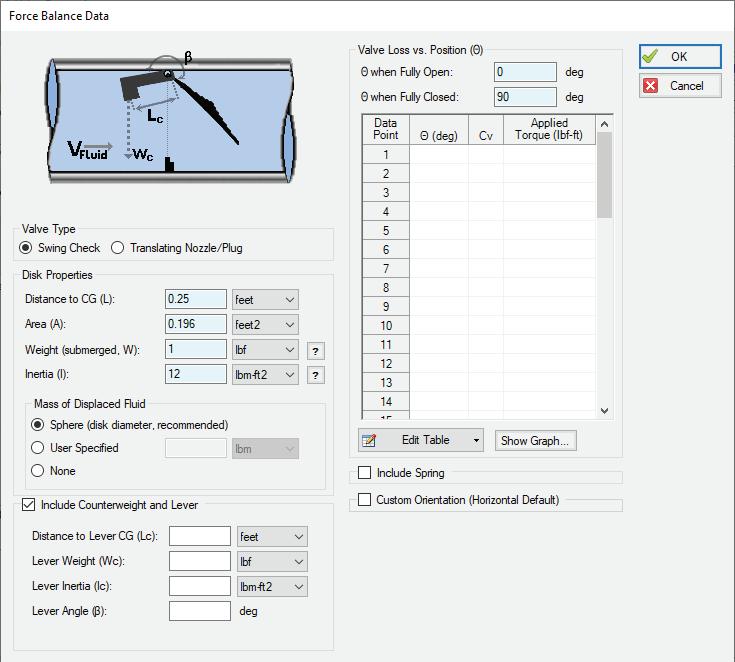
Counterweight Check Valve
Enhanced the Force Balance Swing Check to allow the inclusion of a counterweight and lever arm.
The Force Balance Swing Check Valve model has been enhanced with the ability to include the torque provided by a counterweight and lever arm.

Simpler Force Definitions
Difference forces spanning more than 2 pipes no longer require the definition of a group.

4-Component Slurries
Unlike simpler models that account for only one or two slurry regimes, the 4-Component model automatically determines the effects contributed by each component regime. The model divides slurry solids into four distinct groups based on the particle size distribution.


Specify RPM to Evaluate Pulsation Levels
Directly specify an RPM to evaluate pulsation levels for, instead of only evaluated worst-case frequencies.



Full list of new features AFT xStream™ 3
ADDITIONS & IMPROVEMENTS
• Zero-Length Connector Improvements - Now behave like standard pipes, including selection and graphing tools.
• Distinguish User and AFT Fluids - Easily find custom entries.
• Control Valve Fully Open Cannot Regain Control - Keeps the control valve in a locked-open position during transients.
• Simpler Force Definitions - Difference forces spanning more than 2 pipes no longer require the definition of a group.
• API 618 Limitations in PFA Module - API 618 outlines frequency-dependent pulsation limitsyou can now check for violations graphically, and see locations where the limit is exceeded.
IMPROVED IMPORTING
• Import Bend r/D - Import with appropriate r/D
• Import Speed Increase - Import up to 10x faster
• Better Defaults and Display for Imported Models
• Improved Import of Pipe Material Links
• Display CAESAR II Node Names as junction names.
BEHIND THE SCENES IMPROVEMENTS
• Graphing Optimizations - Provides additional stability now and more capabilities in the future.
• eLicense Access Improvements - Improved security and the release of license seats not in use.
• Output Improvements - Improvements to backend output code provides additional stability.
• Timed Recovery File - Automatically generate a backup of your model to recover unsaved work.
OUTPUT PARAMETERS & MESSAGES
• RPM Output Parameter - Report speed in RPM, in addition to percent.
• Dimensionless Heat Transfer Output Parameters - Grashof, Nusselt, Prandtl, and Rayleigh Numbers have been added as Output parameters.
• Valve xT Output Parameter - Report and graph the xT value used for valves.
• Estimated xT Output Parameter - Provide estimated xT value as used in the solver for valve loss models that do not use the Cv/xT loss model.
• Profile Graphs for Temperature Saturation and Temperature Superheat - Graph temperature above saturation (superheat) along flow paths.
• Laminar Caution - Alerts the user if flow at junctions is in a laminar range.
• POR/AOR in Compressor Summary - Show the values for Preferred and Allowed Operating Ranges in the Compressor Summary.
• Events Messages in New Format - Events are now shown in a cleaner, collapsible format similar to Warnings.
AFT xStream 3 AFT xStream 2 AFT xStream
The Workspace Layers toolset significantly enhances the model building process. Easily update Pipe & Junction size, color, Display Text, visibility, and more from a centralized location
The new Valve Window now clearly distinguishes between different data sources such as User Specified, Characteristic, or Handbook, to understand the available options
Retain Partial Transient Output to access and analyze the results up to the point where the simulation was interrupted
Model single or double-acting multi-cylinder reciprocating compressors, accounting fully for all fundamental thermodynamics
The Design Alert Manager has been reorganized to improve the process of creating and applying user-defined alerts
Draw on the isometric grid without forcing any particular pipe routing
Transient Checkpoints enable you to save the state of a transient simulation at any given point and resume it later from that exact point
Model transient heat transfer in piping walls, including internal/external convection and thermal capacitance for more realistic simulation
A specialized Method of Characteristics is used to solve the transient mass, momentum and energy equations of pipe flow
The Library Manager (previously the Database Manager) has been completely revised and now offers a consolidated way to use and customize libraries of fluids, pipe materials, junctions, etc.
Updated Analysis Setup window with new areas and better user feedback of items changed or which still need to be defined
Finite tank now allows specified transient heat transfer into or out of the tank, specified tank volume change over time, and more flexible initial conditions
Warnings, errors and Design Alerts shown in the Output are now color coded and organized in a prioritized list for quick review
New equation of state options are available for Soave-RedlichKwong and Peng-Robinson
Run batch runs “silently” in the background to minimize interruptions as each scenario completes
Built-in steady-state solver to automatically initialize system before the transient
Use the NEW online Help System for centralized documentation and examples from your browser
Generates force imbalance files that can be automatically read into CAESAR II ®, ROHR2, AutoPIPE and TRIFLEX ® pipe stress dynamic models
Multi-Scenario Comparison: Data can be compared between multiple scenarios to show changes made
Automatic pipe sectioning based on steady-state acoustic velocities
Pulsation Frequency Analysis
Add-on Module identifies pipe acoustical frequencies to avoid resonance from excitation, especially in systems with reciprocating compressors.

Other Add-On Modules
Below are AFT’s popular add-on modules that will help you extend the capability of your AFT software products.
SETTLING SLURRY
Who benefits from SSL?
Those who account for slurry properties, changing solids concentrations, slurry pump reliability and avoiding excess operating costs.
Why use SSL?
Avoid system failures and excessive operational costs
Prevent plugged pipes and misapplied pumps
Reduce energy usage
Improve system performance
Reduce operating and maintenance costs


PULSATION FREQUENCY ANALYSIS
Who benefits from PFA?
GOAL SEEK & CONTROL
Who benefits from GSC?
Those that need to meet specific hydraulic behaviors while avoiding manual techniques.
Why use GSC?
A powerful benefit of system modeling is the ability to evaluate the effects of changing system parameters such as:
Saving time by avoiding manual iterative analyses
Defining multiple variables and goals at multiple locations throughout the system
Simulating control system behavior


EXTENDED TIME SIMULATION
Who benefits from XTS?
Those who model slow moving transients such as tank fills or empty rates.
Why use XTS?
While steady-state modeling answers many design questions, some questions cannot be adequately answered without considering how systems behave over time.
Users can specify the time duration of the simulation, time step size, control system parameters, and how components such as compressors and valves operate over time.


AUTOMATED NETWORK SIZING
Who benefits from ANS?
Engineers who identify and avoid resonant frequencies in systems, especially in those caused by positive displacement.
Why use PFA?
The module is used to calculate the acoustic resonance frequencies that could damage system equipment.


For those looking to manage their carbon footprint by sizing your system to minimize energy costs.
Why use ANS?
Allow the ANS module to smartly manage your iterations and help you save 10-15% on piping costs and energy costs.


Software Leasing & Consulting Options
QUARTERLY LEASE
• For short term projects
• Support, Upgrade & Maintenance (SUM) is provided during lease term
ANNUAL LEASE CONSULTING
• For long term projects
• Support, Upgrade & Maintenance (SUM) is provided during lease term
S upport U pgrade M aintenance
You count on AFT for important projects.
• AFT Flow Expert Package available in block of 5, 10 and 20 hours and tailored to fit your individual needs
• Get premiere support to help troubleshoot model issues and installation
• Automatically upgrade to the most recent version at no extra cost
As of 2024, all new subscription licenses come with complimentary Support, Upgrades & Maintenance.

Performing a hydraulic analysis can be timeconsuming and contain extensive detail. Let our experts complete the analysis for you.
Flow Analysis Experts
If fluids are your business, find out how PMTG can help you.
Purple Mountain Technology Group (PMTG) is a sister company to Applied Flow Technology (AFT). Based in Colorado Springs, Colorado USA, PMTG is a small group of dedicated engineers who are passionate about hydraulic flow modeling and analysis.
As flow analysis experts, we utilize advanced engineering technology to quickly and efficiently respond to customer project needs in a fraction of the time.


Data with Depth™ Software and services designed specifically for process
manufacturers and distributors.
Datacor is a leading provider of process manufacturing and distribution software that helps professionals maximize productivity, use data as a competitive advantage, and drive smarter business growth. By remaining a single source of trusted technology, upholding a longstanding reputation as industry experts and serving as a partner in business improvement, we help modern businesses optimize sales and better serve their customers.
What We Offer Industries We Serve
Future-Built Configurable Technology and Analytics Made for Your Industry
A Legacy of Longstanding Customer Relationships and Industry Expertise
Tools and Techniques for Improving Process Manufacturing and Distribution

Chemical
Meet and exceed stringent chemical industry needs with specialized technology
Food & Beverage
Maintain a healthy bottom line while matching competitive pricing and strict FDA regulations
Personal Care
Obtain clean, clear-cut views into your core business to respond to industry demands
Industrial
Fuel exponential growth by driving business decisions with greater speed and accuracy
Contract Packagers
Streamline the complexities of contract packaging without sacrificing quality
Coatings
Exceed quality standards and improve customer service with total process control
Packaged Gas
Elevate your business with in-depth analytics, superior inventory control and asset management


February 1992
Trey Walters, P.E. conceived of a graphical pipe flow analysis software for Microsoft Windows 3.1. As a hobby he began to work on the graphics and hydraulic solution algorithms.
April 12, 1994
AFT Fathom™ 1.0 was released. It was the world’s first graphical pipe flow analysis product for Microsoft Windows.
October 1995
AFT Arrow™ 1.0 was released. It was the world’s first graphical compressible pipe flow analysis product for Microsoft Windows.
April 2004
AFT introduces add-on modules. Among the first were Goal Seek & Control (GSC), and Extended Time Simulation (XTS). The Settling Slurry Module (SSL) was first released in 2009, and Pulsation Frequency Analysis (PFA) first released in 2017.
September 14, 2023
AFT celebrates our 30th Anniversary. Around the same time, AFT celebrates an acquisition by Datacor and a new partnership with Chemstations.
January 6, 1994
AFT was legally formed.
August 1994
AFT welcomes Channel Partners. United Kingdom, France, and Venezuela were among the first.
November 1996
AFT Impulse™ 1.0 was released to help engineers simulate waterhammer / surge. AFT had orders for AFT Impulse before it was even released.
April 2021
AFT xStream is released to analyze gas and steam transients. It was released with its own Pulsation Frequency Analysis module.


