The •
THIS ISSUE SAFETY OF PAVERS ON FORECOURTS APPEAL CASE RESULT BELGIUM TANK INSTALLATION APEAIRELAND VOLUM E 31 No" 2
Journal of the Association for Petroleum and Explosives Administration

If you're rebuilding your station, you're probably in a rush for the pipe to be in the ground and te s ted so you can get on with your rea l business of selling fuel.

But don't forget to take a close look at your choice of piping materials.
Here are three things to think about when you choose between ' hard' piping like Dualoy®3000/L and the 'soft' system that 's ju s t come on the market.
For starters, there's fluid h a mmer. Topping off can cause pressure spikes of 20 atm or more. Soft systems use thermopl as tic hoses in the primary with safety factors of 3: 1 or less . That's not a lot of margin for failure Wi th Dualoy 3000 / L rigid w all fib e rglass pip e from Ameron you get a sa fety factor of over 10 :1.
Second, th e re 's UL-listing. Soft system containment do es n't have it. Wouldn't you want the assurance of a
third party like UL that the containment can prevent soil contamination in case of a leak? Yo u have that assurance with Dualoy 3000 / L.
/ ,.We ca n tell you a lot more about the differences b e twe e n ' soft' a nd ' h a rd' buried fuel systems. Fo r your own p eace of mind, ge t the whole sto ry by giving u s a te lep hon e ca ll at 0233 613 884. Today. Yo ur bu s in ess is too import an t to take a chance on anything less than the proven be s t: Du alo y 3000/L from Am ero n
Ameron
OPW have installed more overfill prevention valves world-wide, than all other competitors combined. The OPW 61 SO is designed to be a simple, low-cost solution to positive shut-off of product fill for underground storage tanks.
• Industry standard.
• Ready fitted top-tube a nd deflector guarantees integrity and strength of mounting.
• Top-flange with 0-ring, easy to install. • Less restrictions than compet itive valves. • Distributor network se cond to none • Available in 4" and now a l so i n 3"0
• Overfill prevention valves should only be installed by installers competent to HSG-41

In 1968 Underwriters Laboratories Inc granted our Red Thread pipe the first-ever listing for underground fiberglass piping of petroleum products. Since then more than 20 million feet have been installed

far more than any other fiberglass brand. With a performance record unsurpassed by anyone
containIndependent study shows 750/o of service station piping in 1990's will be fiberglass


The Bulletin publishes many articles in a year, it should also be clear to our readers that apart from technical content many have a commercial element to them. This was widely demonstrated over the last two years in the Steel versus GRP debate. In this issue two letters are published following an article about polyethylene pipe work which will widen the debate on the suitability of all materials.
One thing that emerges from these debates is that common performance specifications are required for tanks and pipe work and Regulators and Oil Companies support this concept. This means that once the performance specification is written any material can be used that has been proved to meet the performance specification. With the rapid change in technology on petrol filling stations we in the UK have not kept up with those changes as far as standards are concerned and have relied upon standards from the US and Scandinavia. The Regulators along with the Institute of Petroleum and a leadincr UK test house are now writing performance specifications will be issued as a Code of Practise by the Institute of Petroleum and will supplement HS(G)41 when published.

The Association is holding its 1993 annual seminar at a new venue. The Metropole Hotel in Birmingham which is part of the NEC complex on 2lst September with the Exhibition also opening on the 20th September. The seminar theme is to concentrate on the changes in pipe work that will come from the new HS(G)41 which is due for publication later this year. The new venue will be better for both exhibitors and delegates, the exhibition hall will be larger and better laid out, and persons who wish to apply for exhibition space may contact the exhibition organiser Chris Knight on 0992 451494.

Cost to delegates this year £38 plus VAT. Reserve the date in your diary.
We regret to announce the death, at the age of 88, of Tom Metcalfe former Chief Inspector of Weights and Measures and Petroleum Officer to the County Borough of Smethwick (Warley) now Sandwell.
Tom, a founder member of the APEA was elected an Hon member of the Association upon his retirement in 1969. A keen supporter of the Association, he was always willing to share his technical knowledge with his colleagues, particularly with the many students who attended the residential schools held at Attingham Park.
He was a past Chairman of the Institute of Trading Standards Administration. Author of numerous weights and measures text books, lecturer and one of a small band of experts in his chosen profession.
In recognition of his outstanding services to the Institute, he was accorded the rare honour of being appointed a Vice President of the l.T.S.A.
An active man, both mentally and physically. In his later years he took a keen interest in cricket and was a highly respected member of the Warwickshire County Cricket Club.
His wife a years ago. We extend our condolences to his immediate family including his devoted grandchildren.
Figures issued by the Institute of Petroleum show that in 1992 inland demand for petroleum products in the United Kingdom decreased by 0.3% compared with the same period in 1991.
A total of 74,263,698 tonnes was delivered compared with 74,506, I 02 tonnes for the previous year.
Deliveries of Petrol decreased by 0.5% in 1992. However, deliveries of Unleaded Petrol increased by 13.5% and accounted for 46.9% of all petrol deliveiies. Deliveries of Automotive Diesel also increased by 3.7%.
Increases in deliveries were recorded for ATF-Kerosine, up 7.9%; Burning Oils, up 3.7% and Lubricating Oils & Greases, up 0.2%.
Falls in deliveries were recorded for Gas Oil/Marine Diesel Oil, down 3.3%: Fuel Oils. down 6% and Bitumen. down 1.2%.
Somerset county and Mendip district councillor Robin Gould walked free from court when the prosecution offered no evidence against him in a case brought by the county's trading standards department.
Last July, the councillor was fined £750 for failing to make two underground petrol tanks safe at the site of his redundant garage in Pilton.
Mr Gould turned up at Shepton Mallet macristrates' court • • b mtendmg to deny an identical charcre of still failincr to b b comply with the improvement notice. But there was a last minute notification from the county council indicating that no evidence was to be offered.
The 50-year-old councillor, who is also leader of the Tory group on Mendip, promptly left the courthouse.
The council's advocate went on to explain to magistrates that, whereas the normal procedure would have been for the redundant tanks to be filled with either concrete or diesel to disperse potentially dangerous petrol vapours. Mr Gould had gone ahead off his own bat by filling them with waste oil instead.
Mr Foster said this was now acceptable to the fire authority and, while there had been a lack of consultation on the part of Cllr Gould, the county council saw no point in pursuing the prosecution.
But the county council wished him to make it clear that despite the way the matter was now being dealt with, their decision was in no way influenced by the fact that he was a member.
The case was dismissed.
Mr Gould had no comment to make later.
Over forty members attended the meeting held in Cambridge at the Fire and Rescue Service Divisional H.Q. on November 25th, 1992.
John Boudry
Andy Gaves
Brian Taylor
Mike Alston
The following members were elected to the following Branch positions:Chairman Vice Chainnan Secretary Auditor Executive Committee
Tony Hyde, Colin Brown, David Durham.
Once the business side or the meeting was dealt with a Seminar on Tank-Testing took place.
Jim Luke set the scene for precision testing by talking on the history of tank-testing. Then followed a wealth of expertise on the topic with various speakers imparting their expert knowledge. The speakers includes. David Orpwood. Phillip Whitehead, Barry Dewhurst. Robert Bridges and Rodney Carter who all answered several interesting questions from the floor.
The cnnc_luded with Brian Taylor giving a regulatnrs v1ewpo1111. Brian Taylor stressed the need for accurate precision tank-testing and for Petroleum Officers to become fully conversant with the latest technology on the market.
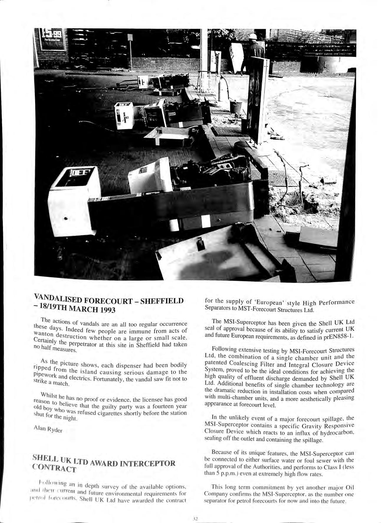
l S/19TH MARCH 1993
T h e ac ti o n f th s o va nd a ls a re a n a ll too reo u]ar occ une n ce e s e d ay 1 o W s nde e d f ew p eop le a r e immune fr o m ac ts o f a n to n d e s t · · I C 1uct1 o n w h e th e r o n a la r ge o r s m a l I s ea e e 1ta ml y th k no h· If e pe rp e trator a t thi s s ite m S heffield h ad ta e n a mea s ure s
A s th e p · t · · d "I ri P p e d f. ic u1 e s h ow s , eac h d i s p e n se r h a d b ee n b o 1 y Pip t o m th e i s l a n d ca u s in g s er i o u s dam age t o th e ewo rk and I f. Str" k ' e ectn cs. Fo rtu n a te ly, th e va nd a l saw 1t not to · 1 ea matc h
reaWsohil s t he h as no p roof o r ev id e n c e, th e li ce ns ee h a s g oo d ' n to b 1 o ld b e ie ve th at th e o uJl ty pa rty was a fourt ee n ye at o y w ho 0 · s hu t f w a s re fu sed c ig arettes s hortl y befo re th e s tat ion 0 1 the ni g h t.
A la n R yd e r
h>l low in o · 11 · d 0 a 111 e pth s ur vey o t t h e av a il a b le o pti o ns , ;in</ 1h e 11 c u rre nt a 1 f' · · f · nc utu re e n v iro n me nt a l re q u ire me nt s 0 1 Pl' ini/ lci r eu iu rt s S he ll U K L td h av e aw a rd e d the co ntra c t
The MSI-Sup ercepto r h as be en g iven th e S h e ll UK Ltd sea l of ap p rova l beca use of its a bility to sati sfy c urre nt UK and future European requi re me nts, as defined in p rE N 8 5 8 I
Fo ll ow in g ex ten sive tes tin g b y MSI-Fo re c o urt Stru c tures Lt d , the combin a ti o n o f a s in a le chamb e r unit a nd th e p a te nted C oa lesc in g Filt e r a nd Inte o- ral Cl os ur e D ev ice Sys tem , pro ve d to be th e ide a l for ac hi ev in g th e hi g h quality of effluen t di sc h ar oe demanded by Sh e ll UK Ltd. Additi o na l be nefit s of sin gl e c hamber tec hn o logy ar e th e dram atic re du ct io n in in s ta ll a tion c o s ts w he n co mp ai e d w ith multi- ch a mb e r uni ts, a nd a mo re ae s th e ti ca ll y pl e as in g ap peara nce at forecou rt le ve l.
In th e unli ke ly eve nt of a m aj o r fo reco u r t s pill age , th e MS I -S up e rce p to r co nt a in s a s p ec ifi c G rav it y R e s pon s ive C lo s ure D ev ice w hi c h reac ts to a n influ x of hydroca rb o n , sea lin g off th e o utl e t a nd co nt a inin g th e s pill age
B eca use of it s uni q ue feat ure s , th e MSI-Su pe rce p to r ca n be c o nn ec ted to e ithe r s urfac e wa te r o r fo ul sewer w ith th e fu ll a pp rova l of th e Aut ho rit ie s, a nd pe 1fo rm s to C la ss I ( less than 5 p p .m .) e ve n at e xt rem e ly h ig h fl o w rate s.
Th is lo n g te r m c omm itm e n t b y y e t a n ot h e r m ajo r Oi l C o m pan y co nfirm s th e M S I Sup e rce pto r , as the n u mb e r o ne se parato r fo r pe tro l fo reco urts fo r now a nd into the f u ture.
DIALCARD and OVERDRIVE agency cards have gained acceptance for use on Triscan's range of Outdoor Payment Systems (O .P.S.).
The O.P.S. systems designed to accept debitJcreditJagency and in-house cards for payment of fuel on petrol forecourts already accepts Allstar, Access and Visa as well as most other major debit cards.
The equipment is offered in two ways , one being a stand alone system an Outdoor Payment Terminal (O.P.T.) or as a pump Integrated Payment Terminal (I.P T.) and links to mo st major pump consoles to provide out of hour s se rvic e or a fast lane facility.
The IN-SITU KW140 Monitor recently introduced by LINK HAMPSON is designed for detecting petroleum products in monitoring wells. Its simple construction and low cost makes it suitable both for those people who want to continuously monitor an environmental well and also those who just want to check monitor at periodic intervals.
The IN-SITU KW 140 monitors the entire well continuously , regardless of groundwater conditions , the sensing element detects petrol and petrol vapours entering wet and dry monitor wells and will also detect diesel fuel and heating oil in liquid form.
The KW 140 requires no electrical connection and therefore can be simply retrofitted or used as a periodic testing system thereby reducing the investment without reducing commitment to leak detection and environmental monitoring. To check for any product leaks requires a simple visual check of the sensor body.

The KW140 friction fits over a standard 4" diameter well casing , although it can easily be adapted to a 2" size Installation involves measuring the depth of the well sizing and attaching the sensor and weight retrieval line and then lowering the sensor and weight into the well and positioning the monitor on the well casing.
The response time to the presence of product of the UL LISTED IN-SITU KW140 is related to ground conditions and temperature together with the concentration of product.
FOR MORE INFORMATION CONTACT PAUL REYNER ON 0635-524200.
On Thursday 12th November 1992 Duncan Tucker Ltd of Pymore Mills, near Bridport, Dorset, pleaded guilty to four breache s of their Petroleum licensing conditions. Duncan Tucker Ltd is the trading name for Solent Furniture Ltd., a subsidiary of the Relyon Group, who manufacture kitchen cabinets.
On the 11 th May 1992 a routine inspection was made of the Company's petroleum mixtures store. A large amount of petroleum mixture (approximately 200 gallons) was found to be stored outside the can store. The production manager claimed that these cans had been delivered that morning but an in spection of the delivery notes revealed that some of the stock had been delivered five days prior to this date and the remainder of the stock had obviously been stored outside for considerably longer as many of the cans were very badly corroded.

It was also found that the can store had been extended without the approval of the Licensing Authority. A check on the quantity of petroleum mixture s held in the store revealed that there was approximately double the licensed quantity held
On another part of the premi ses a number of 200 litre drums were found stored outside the spraying building . The se drums were part-filled with used gunwash which was found to be a petroleum mixture. They were not sealed in any way and so presented a serious fire hazard.
The Company was fined a tot a l of £3,000 with £311 co sts
During the last 20 years, pavers have become an important surfacing material for roads, car parks, industrial areas, domestic hardstandings and, since the late 1970s, petrol stations. Because a paver surface comp1ises concrete, clay or natural stone laid into a sand bed with sand jointing, the surface is permeable. There is a view that paver joints seal with use and time so that eventually the surface becomes sealed. Whilst this phenomenon undoubtedly occurs in some areas, e.g. between the wheel paths at bus stops, there are many areas of pavers where the joints remain permeable. As discussed later, Smith'' 1 has reported that pavements which have sealed can be subsequently unsealed by certain types of traffic. One of the principal for a pavement is to protect the underlying matenals mcludmg the ground from ingress of moisture. Therefore, the potential ingress of fluid throuoh a paver surface a relevant !ssue in all categories of and is doubly important 111 petrol stations where a leaking pavement can create safety and environmental hazards.
This paper seeks t.? quantify the amount of fluid which can be expected filter through a paver surface. It also proposes a test can be used in the field to assess by how much existmg forecourt is leaking. The test procedme and is described in the Appendix and is to become widely used as authorities seek to with European legislation applyino since the beginning_ of 1993. petrol station paver are with a _fuel re_s1s_tant _liquid pre-polymer developed spec1f1cally to and for this reason, the prepolymer has been mcluded Ill the test program reported in this paper.
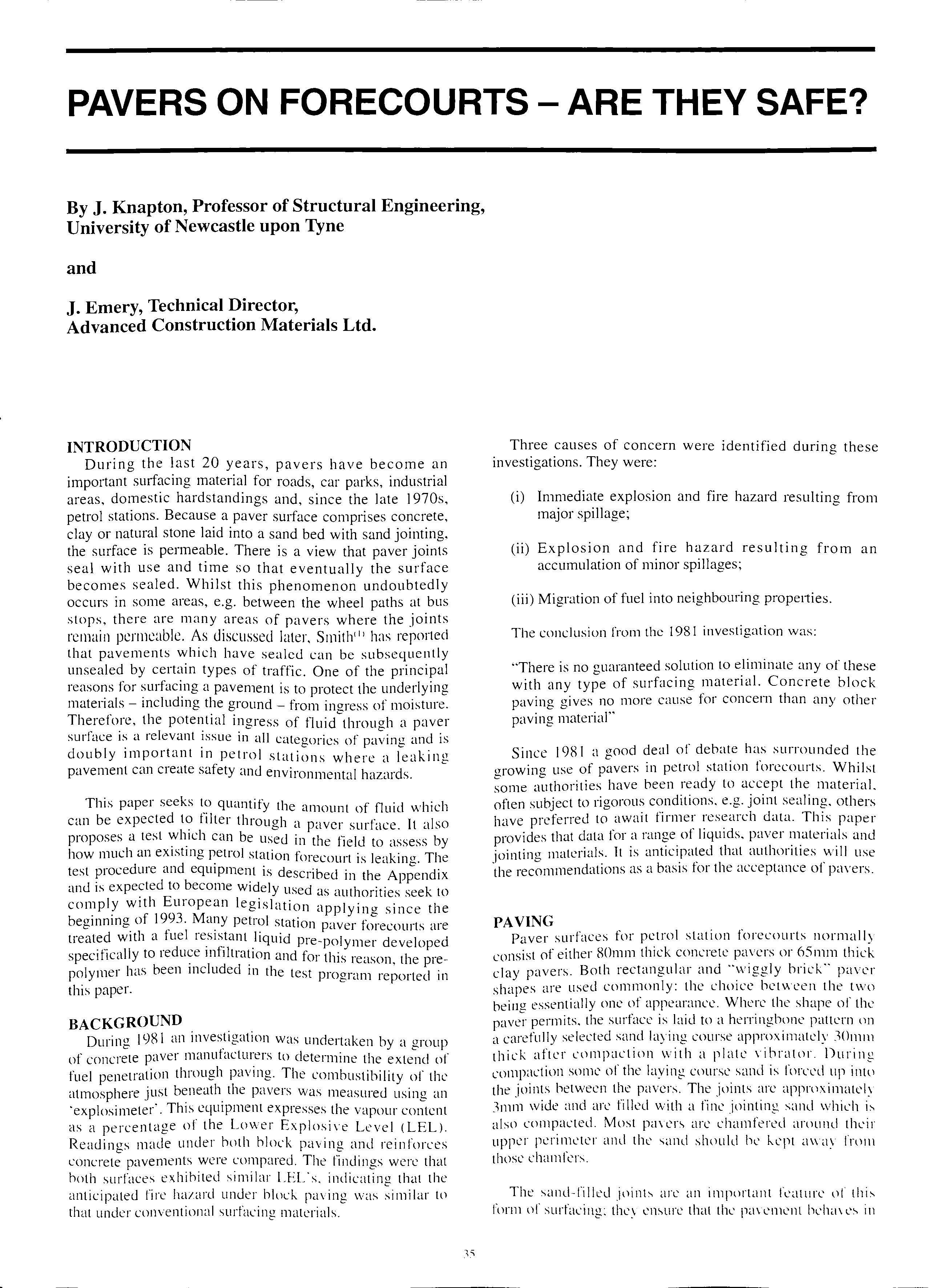
During J981 an inves_tigation was undertaken by a group of concrete paver manufacturers to determine the extend of fuel penetration through paving. The combustibility of the atmosphere just the pavers was measured using an ·explosimeter'. This equipment expresses the vapour content as a percentage of the Lower Explosive Level ( LEL). Readings made under both block paving and reinforces concrete pavements were compared. The findings were that both surfaces exhibited similar LEL's. indicating that the anticipated fire hazard under blod; paving was similar to that under conventional surfacing materials.
Three causes of concern were identified during these investigations. They were:
(i) Immediate explosion and fire hazard resulting from major spillage;
(ii) Explosion and fire hazard resulting from an accumulation of minor spillages;
(iii) Migration of fuel into neighbouring properties.
The conclusion from the 1981 investigation was:
"There is no guaranteed solution to eliminate any of these with any type of surfacing material. Concrete block paving gives no more cause for concern than any other paving material"
Since J981 a good deal of debate has surrounded the growing use of pavers in petrol station forecourts. Whilst some authorities have been ready to accept the material. often subject to 1igorous conditions. e.g. joint sealing, others have preferred to await firmer research data. This paper provides that data for a range of liquids, paver materials and jointing materials. It is anticipated that authorities will use ·the recommendations as a basis for the acceptance of pavers.
Paver surfaces for petrol station forecourts normally consist of either 80mm thick concrete pavers or 65mm thick clay pavers. Both rectangular and "wiggly brick" paver shapes are used commonly: the choice between the two being essentially one of appearance. Where the shape of the paver permits, the surface is laid to a herringbone pattern on a carefully selected sand laying course approximately .10mm thick after compaction with a plate Yihrator. Durinf.! compaction some of the laying course sand is forCL'd up the joints between the pavers. The joints are approximate]\ .11111;1 wide and are filled with a fo{c jointing sand which i·,. also compacted. Most pavers are chamfered around their upper perimeter and the sand should he h·pt away from those chamfers.
The sand-filled joinh arc an impurtant feature of thi;. form of surfacing: they ensure that the pm l'lllent hehaH'" in
Fi g ure 1 Typical section throu g h blo ck pavement.
a similar way under load to a conventional flexible pavement and that interlock is developed between individual blocks. Thus, when a wheel load is applied to a paver, the load is spread to adjacent blocks. Interlock can be defined as the inability of an individual paver to move in isolation from it s ne ighbour s Becau s e of thi s a p a ver pavement can be de s ign e d by s tandard method s for flexible pa vements, the p a ver s and their sand beincr s ub s tituted for an equivalent thickn ess of bituminou s ma7erial. The g eneral arrang e ment of paver pa vements is shown in Fi g ure 1.
Re se arch in the US by Smith <11 ha s s hown that paver surface s s hould alway s be a s sum e d to permit the infiltration of water.
Smith state s :
" Concrete block pa vin g pl ac ed on a s and and gra vel bas e , trafficked by automobil es, do es not alway s have the joints fill o ve r time with detritu s (cre nerating a high run off c oe ffi c ient). The sealin cr of sediment and detritu s in th e joints may be ne;a ted o r eve n re versed by s uckin g a nd pumping action of a uto m o bil e tire s on the concret e block pa vincr'' b
Furth e r inv es tigation work by Kn a pton <21 concluded that: "( i) Th e in g ress o f m o is ture through bl oc k p a vin g can have a marked effec t up o n th e stru c tural pe1forman ce of th e IY b. · f ave ment ; ( ii ) Und e r a n a dv e r s e c orn 1nat1 o n o wate r, m ate rial and tra ffi c. a co nc re te blo c k pav e ment ca n s ig nifi ca nt leve ls . o f ruttin g a ft e r a fe w thou sa nd OOO kg stand a rd a x les , eve n th o ug h th e re quirem e nts of B S7533(3) a r e sat i sf i e d ; ( iii ) Th e a ppli ca ti o n of a P 0 1y m e r sea le r t o a full y g r a nul a r co n c r e te bl oc k pc1ve rn e nt ca n res ult in a s ig nifi ca nt improv e m e nt ID p av e m e nt pe rfo rm a nce. "
Fo ur cirea" o f rec wn g ul a r pave rs we re pre pa re d , two us in g XOmm thi ck c o nc re te bl ocks a nd t wo us in g 65 mm thi ck clay
pavers. One area of each type of paving was sealed using a proprietary liquid pre -p olymer. 140mm diameter glass cylinders, lOOmm high havincr a wall thickness of Smm were to each panel an epoxy mortar to form a water-tight seal at the paver/glass inte1face. (see Figure 2)

Water, Avga s (aviation fuel) , petrol and diesel were carefully poured into each cylinder and the infiltration rate s in ml/second were mea sured for each A half litre same of was us ed for e ach te s t, which is equivalent to an 1mt1al h.ead of This height was considered to be appropriate and 1s prob ably more severe than is lik ely to occur (even during spillage of fuel on a service station forecourt).
Fi g ure 2 Infiltra t io n tri a ls a t Newcast l e U ni ve r s ity s h ow in g g lass p e rm eo m ete r fixed to p over 1'.
0
Figure 3 Infiltration test results concrete block paving.
The results of the infiltration tests before and after seaJina are shown in Figures 3 and 4. The concrete pavers provided greater resistance to infiltration before and after sealing than was the case with the clay pavers. Sealing the concrete pavers rendered them virtually impermeable to water. Infiltration rates for petrol and Avgas were similar and provided excellent resistance to infiltration after sealing. The results are presented in terms of ml/sec i.e. the rate of loss of volume of liquid from the permeameter. In order to appreciate these results, consider the value of 0.005 ml/sec for petrol infiltrating a sealed concrete paver surface. The area of the permeameter is l 5400mm 2 so that the above figure represents the infiltration of approximately 1 litre of petrol per hour through a pavement of 1m 2 area in the case when petrol is standing 34mm deep over the pavement. This figure ignores the effect of evaporation losses, which. if taken into account, would reduce the measured infiltration rate of petrol by approximately 8%.

The equipment used for determinina the infiltration rates in the l_aboratory was al_! readily ;vailable and could successfully be used for site testing. Because of this. it is proposed that the test be adopted as the field compliance test FIGS
Figure 4 /11filtratio11 test results clay block pai·ing.
for petrol station pavements. A test procedure to detem1ine infiltration rates for all types of surfacing at service stations is given in the Appendix. The procedure evolved out of attempts to use several different glass/paver adhesives and represents a simple site test for determining whether or not a petrol station forecourt is sufficiently impem1eable.
To determine the effect of the application of the polymer sealer on the skid resistance of concrete and clay pavers, tests were undertaken using a portable pendulum friction tester. The results of these tests are shown in the table.
These results indicate a significant initial reduction in SRV for concrete pavers after the application of the sealer. Experience has shown that the loss is temporary as subsequent trafficking restores the micro texture of the concrete surface as the sealer is abraded. With the clay pavers. SRV values increased after sealing.
The SRV values obtained for the concrete and clay pavers, whether sealed or unsealed. are satisfactory for vehicular traffic and for pedestrian slip resistance.
Investigations into the erosion of jointing sand by Emery< 4 1 revealed that if a liquid pre-polymer was applied to the paving and allowed to penetrate the joints, on polymerisation the jointing sand was not only stabilised but ingress of water through joints and into the underlying pavement structure was reduced to a negligible level.
The concept of stabilisation of jointing sand in block paving was developed initially to prevent erosion resulting from jet blast from aircraft operating at full take-off thrust. Tests carried out on block paving panels by British Aerospace (Military Aircraft) Ltd. at their Hot Gas Laboratory indicated that polymer sealed blocks withstood Harrier VSTOL (Vertical Take-Off and Landing) take-off conditions operating at ambient temperature< 51 • In order to provide data on the infiltration rate of pavers, both with and without the joints treated with a polymer sealer, a series of tests was commissioned at the University of Newcastle upon Tyne. In anticipation of the more widespread use of polymer sea_Iers, the opportunity was taken to measure the skidding resistance of brick and concrete pavers both before and after sealing.
The following conclusions may be drawn from the research programme undertaken at the University of Newcastle upon Tyne.
(I} providing the joints are sealed, forecourts surfaced with pavers are no less safe than those surfaced with traditional concrete slabs: the amount of fuel which can penetrate a sealed paver surface is negligible.
(2) Those paved forecourts which have not been sealed may give rise to unacceptably high LEL. In such cases the areas should be sealed retrospectively.
(3) The sealing of concrete pavers with a liquid prepolymer reduces the infiltration of spillages of the three tested, i.e. A vgas, petrol and diesel to an ms1gn1ficant level.
(4) Sealing of clay pavers also inhibits the infiltration of the same fuels but not to the same order as for concrete pavers. This is due to the fact that clay pavers are more than concrete. The performance of clay pavers in this respect can be enhanced by a secondary application of the sealer. Therefore. it is recommended that clay be subjected to two applications of polymer material within 5m of any fuel pump.
( J Sealing of concrete pa vers renders the surface virtually impermeable to water.
<.6 > The skid resistance value and slip resistance of concrete pav . . 1· 1· ers 1s sat1s ·actory alter sea mg.
l The_ skid resistance value and slip resistance of clay P<tvers is improved after sealino with the pre-polymer tested. e
(8J The e"L1· d · · 1··1 t. t · ·111 the I· : ipment use to detenrnne 111.1 tra H>_1.11<1es abo1atory 1s suitable for in-s1tu lllhltrat1on measure1 · · · llents at existing forecourts. The equipment C<>mpnse · · d'I · .• · s •ea 1 Y available materials. The test procedures die set out in the Appendix.
191 It is recommended that petrol station forecourts "h<>uld he tested for infiltration using all of the fuel which are to he sold there and also using water.
(10) The recommended maximum permitted infiltration rates are:
Water 0.05ml/sec; Petrol 0.02 ml/sec; Avgas 0.02 ml/sec; Diesel 0.02 ml/sec.
(1) Smith, D. R. and Hade, J. D. (1988). "Permeability of concrete block pavements". Proc. of 3rd International conference on Concrete Block Paving. pp 217-223. Pavitalia, Rome.
(2) Knapton, J. (1992). "An investigation into the effects of water penetrating the surface of concrete block paving". Journal of the Institution of Highways & Transportation, Aug. 1992, No. 8, vol. 39, pp 8-13.
(3) BS7533: 1992. "British Standard Guide for structural design of Pavements constructed with clay or concrete pavers". British Standards Institution, London.
(4) Emery, J. (1992). "Erosion of jointing sand from concrete block paving". Proc. 4th International Conference on Concrete Block Paving, vol. 2, pp 295299. Auckland, New Zealand.

(5) British Aerospace Pie (1991). "Report No. BAE-WWTEN-GEN 0013", unpublished data.
(I) Clean the paving surface and chamfers of dust and loose material at each test location.
(2) For each type of fuel supplied and for water position one I 40mm internal diameter by J OOmm high glass permeameter over a representative area of pavers such that there is at least one joint intersection within the test zone.
(3) Mark the outside and inside perimeters of the permeameter on the paver Slllface.
(4) Apply of approved epoxy mortar between the twrn CHcles. The width of the mortar should be approximately 5mm.
(5 J Set in permeameter into the epoxy mortar and press firmly into position such that a complete seal is made_ between the base of the permeameter and the swface ot the pavers. Pay particular attention at chamfers and use additional epoxy mortar where required.
(6) Allow epoxy mortar to cure in accordance with manufacturer's instruction.
(7 J Pour 500cc of the liquid into the permearneter. record the time and measure the depth of the liquid immediately. expressing the result to the nearest whole mm.
(8) Record the time taken for the fluid level to drop by I0111111. Use the following table to assess the infiltration rate.
for Determining the Infiltration Rates of Fluids Through Paving Using a Falling Head
Time taken for fluid level to drop lOmm
1 minute 10 minutes 20 minutes 30 minutes 40 minutes 50 minutes (stop water test) 60 minutes 70 minutes 80 minutes 90 minutes 100 minutes
Infiltration Rate 110 minutes 120 minutes 0.023 0.022 0.020
(ml/sec) 2.50 0.25 0.128 0.085 0.064 0.051 0.043 0.037 0.032 0.028 0.025
130 minutes (stop fuel tests)
(9) For each test, record the following on a copy of the specimen form
(a) One of the above times (b) Whether the pavement passed or failed (c) Date of test and whether rain occurred during the test (d) Whether the test was undertaken beneath a canopy or in the open. Note that a test undertaken in the open is invalid should rain or other precipitation occur. (e) The address of the site.

Details of tester:
Name: Organisation: Address: Telephone:
Details of filling station: Company: Address: Telephone: On-site representative:
Details of test:
l Omm drop time for water
* 1Omm drop time for petrol
*I Omm drop time for A vgas
*I Omm drop time for Diesel
Date of test
Details of precipitation
Test beneath canopy *Yes/No
*Delete as appropriate
Note:
Top copy to be retained by tester
minutes *Pass/Fail minutes *Pass/Fail ........ minutes *Pass/Fail minutes *Pass/Fail
Second copy to be left with filling station representative Third copy to be sent to:
Chief Petroleum Officer
(address) Tel: Fax:
The pound is floating outside the confines of the ERM but it seems that tanks in pea shingle surround are floatmg out of the confines of their exavations (I jest)! Recently, following the return of water tables to more normal levels, tanks in the course of installation following backfilling with pea shingle, have broken the holding down straps, and floated to the surface at two locations.
Discussion with both installers has shown that they h ad not sufficient thought as to why the straps were and what function the straps perform. Traditionally with water filled tanks and concrete surround two or three straps have been used to keep the tanks in position. This is being continued with empty tanks and pea shmgle surround. Investigation has shown that there was over the function of the straps and their part in the 0 dmg down system which also includes the base or sleepers and the pea shingle surround.
h!he tank base concrete or sleepers provide a platform to : ich the tanks are anchored usincr the straps. The mass of ackfi]] material bears on the .ba;e and together with the masses of the base and tank prevent the tank from lifting.
th In order for the system to work effectively and prevent e tank fro · · · · 1 anch m nsmg it is imperative that 1t 1s secure Y th ored to the base. If the tank is not adequately secured or tl e upthrust on the empty tank exceeds the breaking strain of ie strap. .· on) s causmg them to break then. m such circumstances, tanky _the mass of pea-shingle on top of the tank keeps the m the ex · k · d to the cavat1on. Conversely whilst the tan 1s secure shin 1 base then the three masses of the tank. base and pea . g e oppos th e e ground water upthrust.
The calcul· simpl ation for the upthrust on the tank 1s quite a e one:
Where U _ from t· k- upthrust. V = tank volume. h = height of water ctn hase · h · · · ''' den.· · · 111 t e excavation D = tank d1amete1 F sny of Water or For fully f] the upth. Ooded ground conditions on a 50 OOO litre tank I LI st ::: 2!l.illlli x I IOOO
\ 20 000 1 == 50 tonnes Ilietank llh fill' mass ho! . wou c e .'W tonnes. . , , h thng the tank down = the mass of the tank + 111,1.., '''I e has• · e + Ill ass of the pea-shmgle.

For a typical 50,000 litre tank excavation:
Mass of tank Base Backfill Total
= 10 tonnes = 30 tonnes =40 tonnes = 80 tonnes
There is therefore a 30 tonne safety margin.
Straps must be rated accordingly and the upthrust load catered for plus a margin of safety. increasmg the number of straps divides the load between them and hence, for the example given, options could be:-
2 straps rated at 40 tonnes 3 straps at 26.67 tonnes 4 straps at 20 tonnes.
All turn buckles must be suitably rated.
To return to the two cases where the tanks floated; the straps. were rated at 11 tonnes breaking strain and as were supphed a 33 tonnes holding down capacity was available. As the evacuation was totally flooded 50 tonnes of upthrust was applied to each tank and it was not surprising there'.ore that the tanks floated. In both cases (a four tank installat1on) the total mass holding the tanks down was in excess of 400 tonnes or I00 tonnes/tank. As the figures calculated show· the was nothing to do with the use of pea-shingle. as backfill material but due to the fact that insufficient attent10n was. paid to the number of straps used and their stram. Once free of the straps the tanks have only thelf own mass and a cover or backfill preventing flotation, much less the 50 tonne upthrust experienced by each tank. These mc1dents have shown that the old days of "two or three do" are no longer appropriate when .the new mstallat10n methods are used and both suppllers and installers must ensure that the straps and their number used are sufficient to prevent flotation.
On.ce installation is complete the mass of the matenal 1e. make-up material and final load bearing slab is sufficient to prevent flotation of an empty tank but where cover is limited then the strapping system must be capabk of providing as long as period of use as the tank to which it is fitted.
A Cumbrian village filling station which has been involved in the sale of petroleum spirit since the I 920' s has closed following a series of appeal hearings.
Distington Motors in the heart of the village of Distington near Workington had been under threat since I 982 when the Licensing Authority advised the owner that thence would not be renewed in December 199 I. The reason given then was that the Public Protection Committee of the County Council had decided that in order to maintain a satisfactory standard of health and safety, existing licences would not be renewed after 8 years for installations where petrol was dispensed over the footpath. In addition the Committee also decided that where petrol was stored under a building and the people within the building could be at risk a petroleum licence would not be renewed after I O years.
Distington Motors fell within both these categories and in an effort to bring the site to current standards, Cumbria Fire Service finally issued an Improvement Notice listino 6 major The _licence lodged an appeal but fhis was received outside the time limit. However the matter was taken before an Industrial Tribunal where the licensee applied for an extension in time to lodge a full appeal against the Improvement Notice.
The Industrial Tribunal, after hearing ev·d f· tl 1 d d .d d 1 ence 1om 1e pmt1es mvo ve eci e that it had been practicable for the Appellant to lodge an within the time limit and found they were unable to extend 1t.
The Licensing then informed Distington Motors that the pet10Ieum licence would t b . d d. 1 no e 1en ewe The licensee imme iate y lodged an appeal to th S . e ecretm·y of State for Employment m London against the refusal to re license.
A partner in _the Di_stington Motors firm, Mr J R Grant. at his appeal heanng said that he would comply with the first three items of an Notice relating to the testino of the tanks, suction Imes and vent pipes, the other relating to the positioning of the underground tanks which were beneath the building, the siting of the petrol dispensers, installation of interceptors and the provision of a road tanker stand were matters he wished to discuss.
He said that the space on the site precluded any relocation of the tanks and his only option would he to partly demolish the building to create sufficient space. The cost of this would be prohibitive.
There were two petrol pumps; one 14.5 feet from the road and the other 3.5 feet from the road. He said that so far as the latter pump was concerned he could remove it and by linking the two 300 gallon petrol storage tanks could operate on the basis of use of one pump alone. Regarding the installation of an interceptor Mr Grant said he had made enquiries at petrol stations within 6 miles of Distington and had established that 9 of these had interceptors but 7 did not. He thus queried the requirement on the basis that it was not a universal provision.
With regard to the provision of a tanker stand he explained that his suppliers used a small tanker and that if he removed the unused petrol pump then a tank stand off the highway could be provided.
Divisional Officer Roland Hutton represented the Fire Service. He said that in excess of 670 premises within the County had been checked specifically against six criteria; these were petrol storage tanks inside buildings, over pavement filling of vehicles, containment on site, provision of tanker stands, access for public and staff, and pollution risks. A total of 40 sites were found substandard in these matters and sites with tanks inside buildings and over pavement filling of vehicles were regarded as a top priority for action.

Distington Motors had been found to be substandard in all of the six specified criteria. He said the Licensing Authority regretted the loss of amenity which would result from a cessation of storage and sale of petrol at Distington but he considered the number of substandard safety features were such that they could not issue a further licence until all were rectified. In addition the fact that the appellant's own statement that there were 16 filling stations within 6 miles of the village were at odds with the claim that there would be a Joss of amenities for the village.
In his summing up Mr R C Santon, Her Majesty's Inspector of Health and Safety. said that in his opinion the comhination of hazards would. if perpetuated, represent an unacceptably high level of risk to both the staff of Distington Motors and Members of the Pub Iic.
Taking this and the generally poor standards of maintenance and supervision into account he said he had no reservation in recommending that this appeal should not be allowed and that the decision of the Licensing Authority to refuse to licence the premises should be upheld.

Conder's aim has always been to develop better products and building methods to accelerate the construction process the sooner your forecourt is up and running, the sooner your return on investment. 30 years ago we introduced the prefabricated Canopy, later the GRP Interceptor and most recently the revolutionary Fibrelite Access Covers with their light weight you don't need a 'feat' of strength to lift them. Now, Conder can offer a complete range of ready-made products designed specifically for the forecourt
Modular Convenience Store and Car Wash buildings delivered to site ready wired, plumbed and fitted out for rapid assembly; Access Chambers to contain possible fuel spillage and keep out sub-soil water; Silt Traps to avoid drain blockages and last but not least, Pump Island Barriers all from one source and delivered to site.

The November 1993 edition of the Bulletin contained a short report of the inauguration of the Irish Branch of the A.P.E.A. Following this inaugural meeting, the newly elected committee has got down to work, with the first committee meeting having been held on November 30, 1992.

This committee on behalf of Irish Members of the A.P.E.A. wishes to acknowledge the kind sentiments expressed in the above report reo-ardino- the future of the Irish branch, we are confident we be the first of many.
in the physical planning, control, operations and II!1pacts of Oil Industry activities in Ireland have from membership of the Association quite substantially over recent years, through receipt of the well regarded Bulletin and more recently by attendance at the now Annual Seminar and Exhibition in Dunstable. Irish to Dunstable had their thirst quenched regarding technical updating and their appetite wetted to the good sense of a more participative role in the Association. Hence of the Irish Branch, primarily through the dnving force of Pump Services Limited, the leading Irish Industry Services Company, and the good offices of Jamie Thompson, Brian Taylor and Mike Luo-g from the Council of the Association. 0
The Dunstable event can be recoo-nised as the foremost technical forum for the sector of the Oil in Europe and the benefits of becoming involved in the Ins? Branch of the Association have been equally well recogmsed by Irish Members of the Association, both in Ireland and in the Republic of Ireland. Not least of t ese 1s the op t . · por umty to meet with colleagues rn a st1 uctured yet infor 1 · f I · . ma setting to discuss topics o mutua rnte1 est The side ff E . C 1 · · e ect of Oil Company ngmeers, onsu tants Su 1 s . . C · ' PP 1ers, Technical Sales Staff and Agents, e1 vice ontract k ors, and Regulatory Controllers gettmg to now each othe I b 1 as people rather than business contacts can on Y e an added b · · · f D ·t bi onus. This 1s one of the great benefits o uns a e yet the t f . rans er of information exposure to part1c1pat1on of co . . . ' . . . , . . h nsensus pos1t1ons on vanous topics 1cmam t e worthwhile ob"
So the Irish Branch 1. · D I · as out med by Chairman ec an Ryan. at its fc>i·rna·ti· · . k . .1 . . · on, 1s settrng out to ma e a s1m1 ar contribution t<> th d . . . . . e own stream mdustry 111 Ireland by allmdrng Irish Members from both North and South the 01J1Jortu111ty to get t k d o now each other. to share problems an -.olutrons. and t<> 1"nf'ltre . h "bi I · I · d . nee w ere poss1 e eg1s at10n an regulations.
r·x1·luding the c·1p· ·t 1· w · · · h. h · ' c1c1 Y o hrtegate 011 Refinery w 1c '" < 1pt>rnted by the State Owned Irish National Petroleum < "rp"rai ion: the Oil Industry in the Republic of Ireland I 1 1' a C<> I· · · · L 1111.., I" .., · m J1nat1on of storage operatrons. 1rWl"P"rlillJoll. and marketing activities. all of which are
subject to control under the Dangerous Substances Act 1972 through a series of Statutory Instruments issued in 1979. It was no coincidence that these regulatory controls were issued fairly promptly following the Whiddy Island disaster of January of that year, in which 50 lives were lost, and which understandably focused intense public interest on the events, operating practises and safety measures in place leading up to this incident.
Since 1979, the Oil Industry in the Republic of Ireland with the assistance of suppliers and service contractors has accepted and lived with the Dangerous Substances Act Regulations, but all has not been plain sailing. Their generally perceived hurried introduction in the post Whiddy climate denied the Industry a reasonable opportunity to study the draft legislation before it was implemented. With well over a decade of experience behind us all now, it is generally accepted that these regulations could benefit from revision to accommodate the current direction in legislative control away from prescription and towards standards achievement against accepted codes of good practise and within a framework of policy directives.
Much can be learned by practitioners in the Republic of Ireland from Northern Ireland colleagues regarding the operation, implementation and control of the U.K. legislation for the provision of comprehensive standards for consistent national application without inhibiting technological development. Improvements in product storage and transfer techniques, including spill containment, vapour recovery and driver controlled deliveries are examples where U.K. practises and experiences to date can be examined. This exercise could be particularly well timed in the lead in to deregulation of cross border controls between Northern Ireland and the Republic of Ireland in the post January 1993 E.C. environment.
Substances Act in the Republic of Ireland is admm1stered by Local Authority Fire Officers, as agents of the Department of the Environment under the authority of the of Labour. very significant numbers of applications have been lodged with each of the 38 ma_ior Local Authorities but it is reported that less than 25% of these Authorities have been able to issue such licences, primarily due to lack of resources and the consequent incapacity to enforce proper control as required by the current legislation.
The prospect of the introduction of a new Central Government Authority, namely the Environment Protection Agency, may provide the opportunity to rationalise the Regulatory Control of the Oil Industry in the Republic and attract the required level of resources to allow meaningful
Allied to this prospect, it may prove appropriate for the Department of Labour to undertake a complete review of the Statutory Controls under the Dangerous Substances Act to achieve similar comprehensive consistent standards to those in the U.K. as prepared by working paities drawn from a broad industry cross section under the auspices of the Health and Safety Executive. This is considered to be in the best interests of the Oil Industry and corporate good citizenship, suppliers, service contractors, regulators and not least the public at large.
If the Irish Branch of the A.P.E.A. can make an informed input to the rationalisation of Statutory Controls of the Oil Industry in Ireland it will have achieved a very worthwhile opening contribution.
Dear Sir,
We read with interest the article "Flexible Plastic Pipework for Underground Petroleum Installations" in The Bulletin, Volume 31, No. I.

The author refers to a Swedish National Testing and Research Laboratory's test report when stating that the permeability rate of the UPP Extra is "at 1:,ast an order of magmtude less than the UL reqmrements . The UL97 l requirement is that permeation be less than 1 % volume loss over 180 days.
we are seriously questioning this statement. Indeed, the Swedish test report, of which we obtained a partial copy, mentions a weight loss figure of 0.56 glm for 120, 158 and 190 day periods for UPP Extra pipe. The report does not provide any explanation or details relative to this weight loss ficrure but our knowledge of the field allows us to come to e certain conclusions. Knowing that it takes approximately I 00 days for the pipe walls to saturate and that after saturation, permeation remains constant, it becomes obvious that the 0.56 g/m loss is a daily loss and not a loss for the 120, 158 and 190 day periods. Other laboratories have in the meantime confirmed this figure.
In clear terms it means that for a site with 300 meter of pennanently filled pipes, the yearly permeation loss equates to 75. 7 liter (0.56 g/m/day x 300 m x 365 days + 0.81 kg/liter).
Since 300m of 1'h" pipe holds approximately 340 liter or 275.4 kg of product, the permeation loss expressed in percent over 1 is approximately 11 % ! This is far more than what 1s considered acceptable by UL or ULC.
UL and U!--C are the only. test and approval organizations to have studied and determmed the maximum permeation losses acceptable for underground petroleum piping. Unfortunately, there are, presently in Europe, no minimum requirements in force, comparable to the UL97 I standards.
As manufacturer of double wall piping systems (certified by l!L and mvesting considerable time. efforts and capital to offer high quality and environmentally sound products to the retail industry. we urge the European regulatory authont1es to quickly enforce min. standards in order to preserve the future of t)Jis exciting new piping technology.
Sincerely yours.
F Meersseman.
· · Director TCl-Env1ronment nv/sa Managmg d b .d. 1 . B I wholly owne su s1 iary o e g1um.
Total Containment. Inc Exton. USA
Dear Sir,
I would like to clarify and correct some statements made in the article hy' Michael Lugg '"Flexihle Plastic Pipework for Underground Petroleum Installations".
Mike referred that the UPP product is the onl} system to
be assessed by an accredited European test house.
Ameron Dualoy 300/L was also assessed and accepted by the Swedish Plant Institute under SA 1-1-9846 in 1990. It has also been assessed by KIWA in the Netherlands, an EEC member state test house as well as the UL factory labelling procedures.
My other observation on this apparently very informative and well presented article is that from its title it would at first appear to be a paper that would give a useful factual picture of all the various flexible "plastics" systems that confront the market place. However it seems to be little more than a "Commercial" for a pai1icular manufacturer.
I would also take issue with Mike on the scrap reprocessing of thermoplastics certainly clean scrap are recycled. Scrap polyethylene frequently bemg for refuse sacks, a highly suitable apphcat10n. Very httle non virgin material should find its way into quality piping products.
Glass filament wound epoxy resin pipes are widely used in the Oil and Petroleum industry in an ever increasincr ran ere of applications. For ?ii flow lines up 90 bar pressure and 24 mches m diameter in both desert and arctic conditions constantly out perform steel and high cost alloy products in both cost, installation and long term maintenance costs.
Within the refinery, process lines, fire water systems, cooling water and a whole variety of other applications; offshore glassfiber epoxy resin pipes are now being installed in dry deluge systems that have to withstand I I00°C hydrocarbon fire, jet fire and explosion hazards they have been shown to out-peiform all other materials in tests at the SI Institute Trondheim Norway on behalf of the N01wegian Oil Directorate. A wide variety of other applications offshore utilise these pipes due to their increasingly recognised performance and safety over other materials.
Significant numbers of the World's tanker fleet use our products for lines ballast lines, ine11 gas, condensate and other with approval by all the World major classification society Lloyds. DNV. Bureau Veritas. Germanische Lloyd, US Coastguard. ABS. RINA etc.
Many of the World's military aviation fuel systems push fuels at high pressure through our pipe systems for which there are very tough MIL Specifications.
All these pipes have joints. many get installed in the most arduous of and like all systems finally rely on the skill of the. The strength of an epoxy bonded fiberglas.s pipe mee.ts. or exceeds the ultimate strength of the pipe. therefo'.·e. a JOint that has passed testing is not going to corrode or tail when correctly installed.
Installation time on a site will chiefly dei1end on lh, ·k'll I h'J' t s I and orga111sat10.na a 1 1t1es available. it is ccrtainlv not a factor to do with weather conditions! Sites in Northern Canada. Iceland and Sweden in sub-· I.. . 1 .. h 1 . zeto cone 1t1ons using 1 erg ass .pipe systems are not dl'laved. equally on without delay in the trop.ical monsoons ot Singapore. Malavsia Tl1·11·1-111 I I s I · · ' , l anl , out 1 Ch111a. A .. ram stopped 11lav" allitude 1·s l)ll)\· II . i . t - · •· d OWt'l lo prevail weak site management lack:- control n\'er it·" contractors t11 ensunng are equipped Ill du the JOh. Over 80 per cent ol the sen ice statinns in the LISA and Canada alone use fiherglass pipe in preference to 11ther
major materials. This is especially true of the Oil majors like Shell, BP, Texaco, Mobil, Exxon, Petro Canada and a lot more
With literally several hundred thousand of fiberglass pipe installed worldwide just from Ameron alone, you can feel pretty sure that somewhere before the petroleum even arrives at the forecourt it likely had more than a passing contact with fiberglass pipe and when it gets to the World's forecourts over 100 ,000 of them pump their products through the same.
Yours truly,
RICHARD GRAHAM Petroleum Market Manager EuropeAs leading manufacturers of overfill prevention devices, we have noticed some confusion within the industry, over the last two years, regarding maximum tank working capacities. Different O.P D. manufacturers had been quoting varying percentage figures for final shut-off levels. Accordingly , it is possible that some valves may have been installed without due consideration to minimum ullage requirements.
Following the publication of Statutory Instrument No. 743 last year , The Road Traffic (Carriage of Dangerous Substances in Road Tankers and Tank Containers) Regulations 1992, we had expected to see some unifomilty develop within the industry Schedule 4, para 2 2, states that "In this Schedule, any reference to the maximum working capacity of a storage tank shall be a reference to 97 % of its actual capacity , expressed in litres." Whilst this in itself begs clarification of the term "actual capacity" , we felt that at leas t we could now see the goal-posts.
Our interpretation of S I. 743 is that the tank can legally hold 97 % capacity , once " re-tagging" has been carried out. Thi s will en s ure that there is always a minimum of 3 % ullage Therefore any overfill prevention device must not allow the fuel to exceed 97 % tank capacity , at any time
Consequently, we would suggest that all manufacturers should ensure that their overfill prevention device can be installed with a final shut-off level at 97%. This will ensure that industry standardization is possible . The installation manual for the Emco Wheaton Al JOO O.P.S. valve was amended at the end of last year. It now includes information to enable the fitter to install the O P.D. at 95 % or 97 % level, depending on the customer' s requirements.

One further complication is that existing policy statements, drawn up by oil companies and service station owners, may specify that the maximum working capacity should be 95%. I have attended meetings at three service stations recently where tanks have been retagged to indicate 97 % capacity, but the overfill prevention devices have been installed with a 95% final shut-off level. Obviously, this may be simply because company procedures have not yet been rewritten to tie the future , perhaps this is something that we should be looking at as an industry.
Yours sincerely
GED NORRIS
Emco Wheaton UK Limited Dear Editor,
After removing many underground fuel storage tanks around the UK I thought this particular photograph would show to your readers the current state of some of our tanks. (SEE FRONT COVER).
Believe it or not this particular tank was still in use and has been recently removed
I hope this has been of interest to you all.
Yours faithfully Gwilym Edward s Edwards (Tank Removal) Limited Dear Editor,
Having seen photographs of unusual storage facilities which seem s to becoming a feature series in "The Bulletin ", I thought you might be interested in thi s one.
It was taken in a town 25 mile s north of Vienna in Au stria. The petrol filling station can be seen right on the edg e of the main road. The und e rg round petrol tank s are sited in the town centre green with the Sft vent pipe s an added feature. The suction lines run from the tanks under the main road to th e flowmeters Note th e decorative ivy for the vent pipes '
Yo urs s incere ly
RP BEARDPrin c ipal Tradin g Standard s Officer Dorse t County Co un c il
Conventional methods of investigating contaminated land have typically been limited to soil and groundwater sampling from trial pits and boreholes. On sites contaminated with volatile organic chemicals such as petroleum products, cleaning fluids and solvents, an alternative approach is to undertake a soil gas survey. The presence of volatile organic chemicals in the soil gas is indicative of the presence of chemicals in the unsaturated zone or in the groundwater.
The paper explains the principle of the soil gas survey. The practical application of the technique is illustrated and the impmtance of quality control is explained.

A fundamental prerequisite to undertaking intrusive site sampling of a potentially contaminated site is a desk study. This study should consider a historical review, operational history, geology, hydrogeo16gy, local water abstraction points and other factors. It should be possible after the desk study to have identified any potential contaminative chemicals used on site in order to establish the range of analytical determinands to be considered in the intrusive site investigation. Where the possible contaminants include volatile organic chemicals (VOC's) such as industrial solvents, cleaning fluids and petroleum products, a soil gas survey is likely to be an approp1iate method of investigation.
A release of into the ground will result in migration of the product vertically downwards until it reaches an impermeable barrier or the groundwater table. The product will then spread out as a result of topographical features or the hydrauhc gradient. Those products with a high vapour and low aqueous solubility have a tendency to volat1hse: Therefore once liquid VOC's reach the water table, the spill may be identified by a free product layer, a phase plume in the soil gas and a dissolved phase plume m the groundwater.
Jn the vapour phase, the concentration of VOC's will be , test J·ust above the water table. The vapour 01 e<1 ·11 d"ff. · II · 11 w1 1 use vert1ca y and honzonta . y throuoh the soil to the ground surface where they will dissip7tte into the atmosphere.
In the soil gas survey. a 28111111 diameter hollow steel probe is driven into the ground. preferably to just above the water table. The hollow probe is connected to a small vacuum pump and a flow of soil gas is A representative sample of gas is recovered using a synnge and the sample is then analysed on site using a gas chromatograph ( GC). The analysis for the VOC" s is
typically complete within 10 minutes and the results are then available to refine the sampling strategy to facilitate the most efficient investigation.
the States, where the soil gas survey technique ongmated, it has been used on sites contaminated with a range of VOC's such as tricholoroethylene, trichloroanaline, perchloroethylene, carbontetrachloride, methane and petroleum hydrocarbons.
In the United Kingdom, the soil gas survey is currently principally to detect volatile hydrocarbons notably petroleum spmt. For example where a petrol service station is to be sold or redeveloped at least three of the multinational oil companies specify soil gas surveys as a prescreen to establish whether the station has suffered from any accidental release of fuel.
The quality of soil gas survey results must be validated in a similar manner to laboratory analytical procedures. The GC must be calibrated against analytical standards and regular quality assurance checks must be made. Instrument calibration checks should be run through the sampling lines and system blanks should be analysed to confirm no equipment contamination.
Interpretation of the soil gas survey data is dependent on a number of factors, not least the nature of the VOC' s and the geology of the location.
The investigation of a service station site where underground storage of both petrol and diesel has occuiTed is a good example. The GC would be calibrated to detect total volatile ?ydrocarbons as well as four primary individual constituents, benzene, toluene, ethylbenzene and xylen_es. Diesel '.s not so to the gas suryey techmque as pet1ol to 1t s lower proportion of volatile compounds. For this reason, the criteria for assessino significant diesel. is an order of tower than the cntena applied tor petrol. Usino the GC I . I I h b <IS the ana ytica too. t e profile of the soil gas trace. with the compounds. will provide an indication as to the of the _Some soil gas surveys are undertaken us mg a detector (PIO) as an ahernat ive oht to the As the PID just records total volat1 e yt no mformation is acquired on the nature of the contaminant. therefore intemretatio 1· 1 , 1 1· ,. t n 0 t 1t resu ts 1s ar more u1thcult.
There a_re a other factors which affel·t the 111terpretat1on of the soil gas survey result:- includin" the amount and age of the product lost. soil permeahftit\. mmsture content and the d1sta11l·e from the source. ·
The soil gas survey results can be mapped to give the areal extent of VOC contamination in the subsoil. Where enough gas samples have been recovered this contaminant mapping provides indications on the extent of the plume of contamination.
In cases where the soil gas survey indicates contamination, conventional intrusive investigation techniques can be used far more effectively to recover soil and groundwater samples. The number of monitoring wells can be reduced by eliminating the need for unnecessary drilling.
In the case of a number of sites where this technique is applicable, it is possible that potentially explosive atmospheres may be present, eg. petrol service stations. Clear method statements should be established and adhered to ?Y the consultant/contractor. In the case of a petrol station, the practitioner will not only require permission to undertake the survey from the client and site manager, but also the local Petroleum Licensing Authority.
soil gas survey approach is a rapid investigation technique for sites potentially contaminated with VOC's. ;\nalytical results are available on the day of the investigation and can be used to refine the positions of the sampling locations. Contaminant mappings allow subse.quent intrusive sampling in the 'hot-spot' areas ensunng more cost effective usage of site investigation budgets.

The APEA continues to grow and move forward in all its spheres of activities. It persists in being noticeably successful in representing both Industry and Regulators in a single forum, which is envied both in Europe and the USA. However, this very success has led to a need to change the structure of the national organisation, to make It more dynamic and focused in its decision-making.
Much debate has taken place this year before the structure below was agreed as a way forward, and no doubt fme tuning will need to be made as experience is gained operating with this new organisation.
The previous organisation, which had been operating for a number of years. consisted of one committee called the Council. This consisted of all the national officers of the APEA and had grown to number 20 members in total. It met four to five times a year. All business was carried out by this one committee, or by ad hoe groups.
The new structure retains the council as the final authority of the organisation. hut now includes smaller group» or committees to concentrate on specific activities. They are.
* The Policy and Finance Committee, including Membership.
* The Branches Committee, including European activities.
* The Training Committee.
* The Technical Liaison Committee.
* The AGM and Seminar Committee.
* The Publications Committee, including Advertising and the Year Book.
The agreed responsibilities and membership of each committee are given in full at the end of this report.
The overall objective of this new structure is to make the organisation more dynamic and focused in its operations. To implement this, each committee has a Policy and associated Budget for the ensuing year for which they are accountable.
A number of these committees have already started to operate, but it will be in the 1993/94 year when the structure first takes over completely. I wish it every success.
I am pleased to report that attendance at the 1992 AGM in April and The Seminar in October were both records. Indeed, owing to this success, it is planned to move the venue for 1993 to the Metropole Hotel at the NEC in Birmingham. The dates are the 20th and 21 st September.
The first European Branch of the APEA was formed in Dublin on Monday 21 st September 1992, and thanks goes to all those who made it possible. Further branches in mainland Europe are planned for 1993/94 and beyond.
Other events of note this year include a very successful trip to Holland in June organised by Rob Green. Further visits are planned for the future.
The APEA also exhibited at the Forecourt Show at the NEC for the first time. It proved to be a successful venture and it is planned to attend in 1994.
The two Electrical Training Courses organised were both over subscribed, and felt to be very successful by those who attended. Further courses covering a wide range of subjects are planned for the future, and training will become an increasingly important activity in which the APEA will participate.
This year has also seen the APEA registered for VAT, a sign of its growth.
Lastly, I would like to thank all Council Members for supporting me in my year as Chairman. It has been hard work, often rewarding, and sometimes frustrating, but mostly it has been enjoyable. I wish your new Chairman Mike Lugg all the best during his year.
I. Policy and Finance Committee: (including membership)
1.1 This .c?mmittee would be responsible for day to day adm1n1strat1011 of the APEA not covered by other committees, and in particular for the preparation of policy recommendations to the full Council. as well as all aspects of financial control. It would also ensure that all membership matters are properly -;erviced. and this would include the collection of subscriptions.
1.2 Membership to consist of the Chairman, Vice Chairman, Secretary , Treasurer, Branches Committee Representative , Immediate Past Chairman , and Membership Secretary
2.1 This committee would formulate a common view of all the branches for representation on the Policy Committee and would be responsible for appointing a representative to that Committee and also on other committees on which a Branch Representative sits. In pa rticular , it would be responsible for ensuring the members' voice is heard in the administration of the APEA. It would also be responsible for co-ordinating the activities of the APEA as it moves into establishing a position in Europe.
2 .2 Membership to consist of one representative from each branch.
3.1 This Conunittee would be re sponsible for all aspect s of the training programme and its implementation.
3.2 Membership to con sis t of a Branch Representative appointed by the Branches Conunittee and two others appointed by Council.
4.1 Th e purpose of this Committee i s to answer all technical queries po sed to the APEA. To respond to reque sts for consultation over law guidance notes etc
passed on by the Policy Conunittee. It would also be responsible for liaison with other organisations with which it associates. Much of the busine ss of the Technical Liaison Committee could be done by coITespondence It would be a duty of this Committee to use appropriate experts from within the membership.

4.2 Membership to consist of a Branch Representative appointed by the Branches Committee and three others appointed by Council.
5 1 This Committee would organise and oversee th e Seminar and Exhibition and the AGM.
5 .2 Membership to consist of the Chairman , a Branch Representative appointed by the Branches Conunittee and tlu·ee others appointed by Council.
6.
6.1 This Committee would be responsible for ensurincr that any publications and the associated advertising contained, and s ubs e quent sales, are properly overseen. This would include the setting of adve1tising rates It would also be respon s ible for the generation and overseeing of the APEA Year Book.
6.2 Membership to consist of the Editor, the Advertising Secretary and a Branch Representative appointed by the Branches Committee, and one other appointed by Council.
J.C. SAMSON CHAIRMANThe photograph s s hown on this page and page 51 were take n s howin g the Belgium tank manufacturer VSB method of in stalling double s kin steel ta nk s which make s in s tallation eas ier and s aves o n co ntractor s time. The t a nks are manufactured in th e same way as other european tanks but w ith the addition of havin g a frame at th e bottom of the tank and s tee l s trap s weld ed to the frame. Th e tank s are lowered int o the excavation with a levelled n a tive so il ba se, the
frame then ha s 150 mm concrete poured onto it to form a secure slab to preve nt movement , then granular backfill , in thi s case sand 1s placed around the in stallation. The coating around the s te el tank s is protected where the frame and straps join by the use of a thick butyl rubb er s trip. Mr Berto rnformed th e Bulletin that at least 90 % of the t a nks m a nufactured by hi s company a re built s upplied and in stalled thi s way '


To run a safe and efficient retail petroleum site you must have good control of your wet stock and reliable protection for the environment At the heart of both these functions is accurate, reliable tank gauging.
Veeder-Root Environmental Systems has a wide range of products designed to provide you with the right specifications for your needs, at unbeatable value

Our business is tank gauging and environmental protec tion and we are investing in the future to be a ble to provide the products and services which meet the market's requirements, both now and in the ye ars ahead
Having the right products is only part of the solution and we recognise the need for excellence in service and installation. We operate our own national engineering team supported by technical specialists and our customer care department at Head Office. Their sole purpose is to serve you from enquiry to field support. WHY NOT TALK TO THE WORLD LEADERS? CALL


A WEFCO underground storage tank delivers petrol to the nozzle, where it's needed, not into the ground

That's because at WEFCO we're leading the field in environmentally friendly fuel storage with our double skinned tanks, giving maximum protection against leakage.
Around a conventional single skinned tank we have
an outer skin. Then we have applied a solvent free polyurethane coating to all \ d ' \ external surfaces, adding catho 1c 1 protection where required, for increased I efficiency.
In short, we create a secure leak free I environment; and once the tank is I installed below ground we monitor its 1 performance continually with an / electronic leak detection system.
WEFCO is the only BS5750 accredited company to offer this level of protection
Underground storage is just one aspect of the WEFCO range of services and products, all designed for efficiency, performance and environmental