The · • 1 )
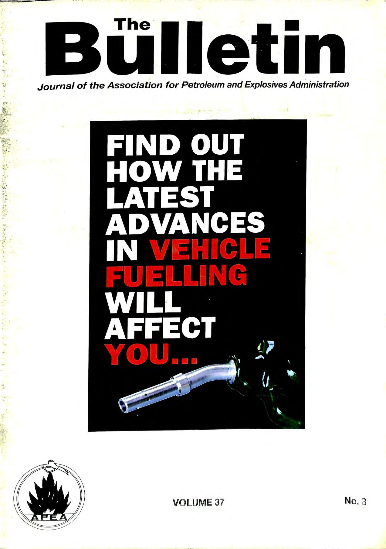
p:1 . '{:.,'':! '-i t:·t ., ,·' l' .. t;:! :,, •4 't." ' ' t ., VOLUME 37 No" 3
Journal of the Association for Petroleum and Explosives Administration
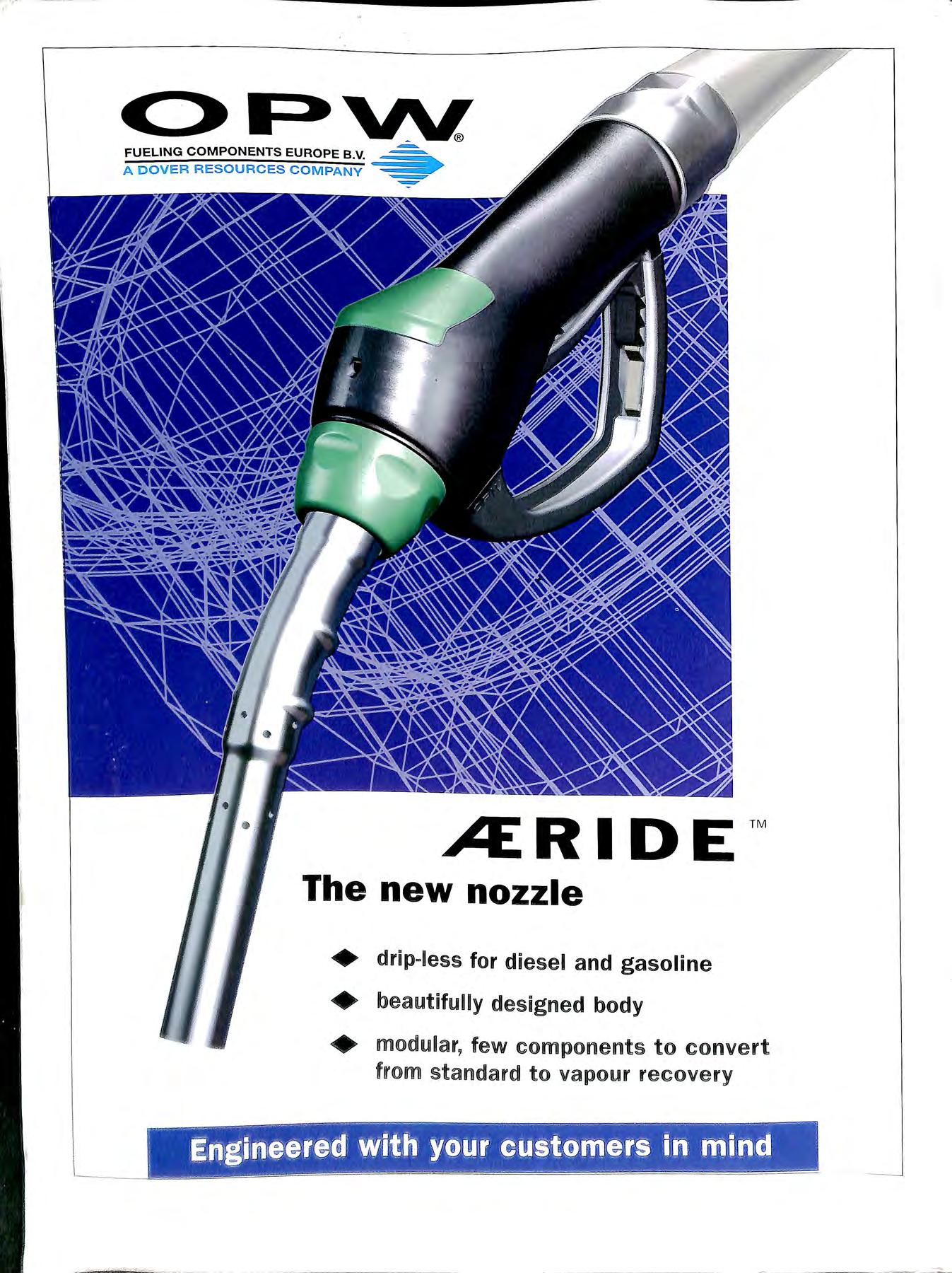
C>F>W. FUELING COMPONENTS EUROPE B V A DOVER RESOURCES COMPANY• ,A:RIDE ™ The new nozzle + drip-less for diesel and gasoline + beautifully designed body + modular, few components to convert from standard to vapour recovery
 Scully On·Truck Computer

0 0 JOSEPH ASH STORAGE TANKS Ma] 1 ENVIROTANK 1

• Tank cleaning • Gas free certification • Safe excavation and removal of petrol tanks • In-situ tank decommissioning • Foamed concrete filling • Hydrophobic foam neutralisation • Mobile oil/water separator for low cost interceptor drainage • Supply of rotationally moulded or GRP interceptors • Emergency oil spill response contractors • Land remediation OTS ar e L icen se d Was t e Carri ers a nd op era te o ur own License d P etrol Tank Di spo sa l Site No: SY- 40 We are a Q u ality Assured Comp any t o ES/EN/I SO900 2 Head Offi ce 0 1386 853409 F ax 01386 8589 28 Bris to l 011 79 304 54 5 Derby 013 32 38 5892 Newport 01 633 25 000 3 Portsmouth 01705 381 066 R eading 01189 50 5 556 ri1lrb OTS Ltd, H ead Office, Springhill lndustrial Estate,Springhill, Moreton -in Marsh, • G-loucestershire, c;LS6 9TP

High integrity pipework systems for forecourt installations Dist ribu ted by PURFLEET FORECOURT SERVICES LTD PURFLEET FORECOURT SERVICES 520 Lond o n Road, West Thurrock, Grays, Essex RM20 3B E P-etrol·line -o_lus Durapipe - S&LP • No 1 UK manufacturer of polyethylene pipes • Superior electrofusion jo i nting system • High flow rates • Availabl e in five sizes for suction, pressure and vapour systems • Competitive prices • Nationwide delivery Tel : 0 1708 863931 Ext 2 19 Fax: 0 1708 864140 e-mail : purfleet fo recourt services@ harris-group .co .uk LEDBURY WELDING & ENGINEERING LTD. NEW MILLS INDUSTRIAL ESTATE LEADON WAY, LEDBURY HEREFORDSHIRE HR8 2SR (TEL : 01531 632222) (FAX: 01531 634718) A COMPLETE RANGE OF ABOVE & BELOW GROUND STORAGE VESSELS QUALITY UNDIERGROUND TANKS .. QUALITY UNDERGROUND TANKS DOUBLE AND SINGLE SKIN LEAK DETECT ION OVERFILL PREVENTION DEVICES MANWAY ACCESS FRAMES MULTIPLE COMPARTMENTS S P ECI AU ST CO AT IN G ABOVE FIUJllY BLINDED roTAllY ENClOSE[) 6 DERV=PACKSi 6(())(()) GAllON TO 2(())i00(()) GAllON "
Ken Wilcox Associates, Inc. • Summaries of 300+ Leak Detection Methods from 100+ Vendors • Third-Party Evaluation Procedures from USEPA, KWA, MRI and Others • Full copies of Third-Party Certifications from Leading Vendors • Fully Searchable and Printable • Software: PC Tank Gauge, Inventory Calculator, Tank Calculator, • Netscape Navigator 4.5 , Internet Explorer 5, Adobe Acrobat 4.0 and more Leak Detection 99 CD-ROM Order by phone, fax, mail, or internet, £70 or US$100 Phone (US) 816 443 2494, Fax (US) 816 443 2495 E-mail: info@kwaleak.com, Web: www.kwaleak.com 1125 Valley Ridge Drive Grain Valley, Missouri, 64029, USA So me supp li ers best engineer ing fo r a Second aryContained Tee Our engineering. r) ! \ I I J \ 1 \ I ! o.., o \ H I 1 11 I" We run the R& Dgiving yo u: Cost sav ing Time savin g ...Yo ur choice 0 2 'ht r • f· tr n ?ft ' . .. PETRO L PIPE SYSTEM l'h oiw + 'l h 22 10- 00 h i \ + -t h 22 f (l(i -\ ()

C.P.INSTALLATIONS (SOUTHERN) LTD. (Established 1968) • Specialists in Petroleum Pipework Installations. • New and existing Tanks & Lines tested. • Modifications to existing installations. • And all work associated with Forecourt Pipework. e Approved for UPP, Durapipe and Enviroflex Pipework Installations. • Approved for Ameron and Smiths Fibreglass Installations. Unit 2, 275 Prince Avenue, Westcliff on Sea, Essex SSO OJP. Tel: 01702 392110 (24 hrs ans) Fax: 01702 392126 WASTE MANAGEMENT . NATIONWIDE FORECOURT . DRAINAGE & INTERCEPTOR SERVICE Cleaning & emptying of interceptors and assoc iated drainage systems found on garage forecourts • Interceptors • Catch Pits • Tank Tops • Gullies • Car/Jet Wash Pits • BucketTraps • Surface Drainage • Below Surface Channels Drainlines Water transported for tank testing plus treatment & disposal of the contaminated water. 'fir EV ESH AM (0 1386 ) 47 190 INDUSTRIAL & TANK CLEANING Petrol, oil & solven t tanks cleaned to OCTEL and Petroleum Industry specifications if GLOUC ESTER (01452) 507432 H ead Offi c e : Grange Ro a d Botle y, So uth a mp ton , 80 3 0 2GD Te l: (01 489) 782 232/ 6 Fax (0 1489) 7 8982 1 CLEANSING SERVICE GROUP LTD PETRO L EUM PIP EWORK SPECIALISTS 0 VAPOUR RECOVERY 0 TANKAND LINETESTING 0 TANK AND PUMP INSTALLATIONS 0 EMERGENCY CALL OUTS 0 2 Bercta Road New Eltham London SE9 3TZ Tel : 01818502211 Fax : Ol81 850 5599 Email : tubeflow l@aol.com D DC BUILDERS LTD FOR SERVICE QUALITY & RELIABILITY WE OFFER A COMPLETE SERVICE ON MAINTENANC E AND IMPROVEMENT WORKS TO THE PETRO L E U M RETAIL MARKET D DC BUILDERS L T D 7 ST CLAIR C LO SE CLAYHALL I L F ORD E SSEX IG5 OPA 0181=550 5216 0181-550 6095

Forecourt Specialists Electrical Maintenance Design Testing Unit2 Gre g o rys Bank Tr ading Estate Wo rcest er WR3 8AP TEL : 0190 5 28402 FA X: 01905 28410 For sa fe hand ling and disposa l. CALL U S FIR S T WE HAVE OVER 25 YEA RS EXPER IENC E IN TH E PETRO LEU M IN D USTRY AND WORK HA RD TO GI VE YOU A QUALI T Y, PE RSONAL SERVICE Professional developmen t TRAINING IN-COMPANY SHORT COURSES • Electrical Requirements for Petrol Filling Stations • Management overview of HSW Statutory Regulations, including : Manag emen t of He alth & Safety at Work Regs (MHSWR) Wor kplace Health, Safety and Welfa re Reg s (WHSWR) Pro vis ion & Use of Work Equipment Regs (PUWER) Person al Prot ect ive Equ ipment at Work Regs (PPER) • Essentials of Health & Safety at Work Sites • Introduction to Health & Safet y Risk Assessment • ELECTRICITY AT WORK REGULATIONS (EWR) • Construction (Design & Management) Regs (COM) • BS7671 Requirements for El ect r ical Install ati o ns (16th Edition Wiring Regulations) • Inspection and Testing of In-Service Electrical Installations • EARTHING AND BONDING Rev iews a w id e ra nge of nati onal Codes of Pract ice and Statutory Requ irem ents Presenter: TERRY HEDGELAND BA. FIEIE. MIQA. Member of APE A and IOP Phone: 01737 553328 BUILDERS TO THE PETROLEUM INDUSTRY • FORECOURT INSTALLATION INCLUDING STEEL & PLASTIC PIPEWORK • SHOP REFURBISHMENTS • EL ECTRICAL INSTALLATION • MAINTENANCE AND REPAIR 01269 831038 FAX (01269) 831201 Th e Asso cia ti on fo r Petro leum and Explos ives Adm in istration
Retrol·line
the complete forecourt advertising kit For further information on the full range of Elaflex products contact: Riverside House , Plumpton Road, Hoddesdon , Herts EN11 OPA. Telepho ne 01992 451494. Fax 01992 451496
A J. Bayliss (Stourport) Ltd Petroleum Engineers Petrol, Fuel Oil and Electrical Installations 11/12 HODFAR ROAD, SANDY LANE INDUSTRIAL ESTATE, STOURPORT-ON-SEVERN DY13 9QB TELEPHONE: 01299 824541-2-3 FAX: 01299 827638 SPECIALISING IN ALL ASPECTS OF FORECOURT PETROLEUM INSTALLATIONS, SERVICING AND PRECISION TANK TESTING FULLY ACCREDITED TO BS EN ISO 9002: 1994 Care For The Environment... Make Forecourts A Safer Place To Work And Visit... Provide Quality Solutions To Forecourt Engineering Problems ... RI SBRllDGER VAPOUR RECOVERY PRESSURE VACUUM VALVES VAPOUR LOSS REDUCTION SYSTEMS UNDER PUMP/ CHECK VALVES DESIGN & DEVELOPMENT INSITE LINE TESTING RIS STOP OVERFILL PREVENTION DEVICE filSBRIDGER LTD Stychen.s Lane, Surrey RH] 4LN Tell : ( + 44 01883 7 43107 Fax: ( +44 01883 744342 J
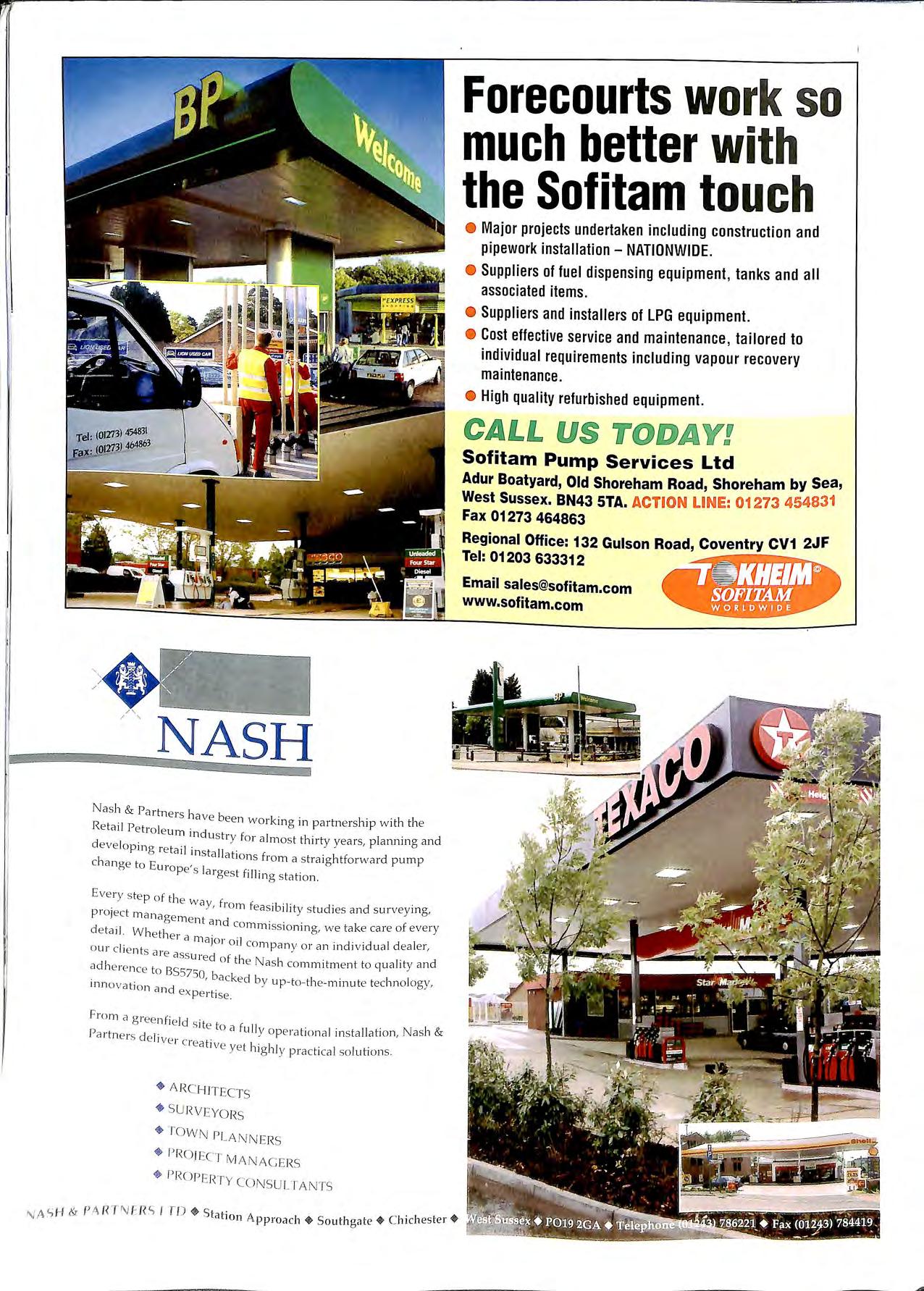
NASH Nash & Partners I b iav e ee n wo rking in partn er s hip wi th the Retail P e trol e um · d d 111 u s tt y for a lm os t thir ty vea rs, plannmg and eve lopin g re tail i II , I ns ta at ion s from a s trai g htforward pump c 1ange to E uro , 1 pe s a i ges t fill mg s tation. Ever y s te p of th e w _ a y, fi o m feas ibi li ty s tudies and survey mg, project mana ge ment d d a n commi ss io ning we take care o f eve ry e ta il. W he ther a ' I ' nia1oi o il co mpan y o r an indi v idual d ealer, o ur c ie nts a re a ss ur d di e o f th e Nas h co mmitm e nt to q ua li ty and a l e re n ce to ::; =>0, backed by up-to-th e -minute tec hn o logy, inn ovat ion a nd expert ise From a g ree nfi e ld · Pa ·t d s ite to a fu ll y o pe rat iona l in s ta ll ation , N a sh & i n e rs e li ve r e re t" a ive ye t high ly pra cti ca l so luti o ns. * A RC HIT ECTS + SU RVEYO RS • TOWN PLA NN ERS + PROJECT MANAGERS * f,l<OP ERT Y CONSU l TANTS Forecourts work so much better wi th the Sofitam touc h • Major projects undertaken including construction and pipework installation - NATIONWIDE. Suppliers of fuel dispensing equipment , tanks and all associated items. Suppliers and installers of LPG equipment. • Cost effective service and maintenance , tailored to individual requ irements including vapour recovery maintenance. High quality refurbished equipmen t. Sofitam Pump Services Ltd Adur Boatyard, Old Shoreham Road , Shoreham by Sea, West Sussex. BN43 STA. ACTION U NE : 01273 454831 Fax 01273 464863 Regional Office: 132 Gulson Road, Coventry CV1 2JF Tel: 01203 633312 Email sales@sofitam.com www.sofitam.com NA SH & 1' 4 RT "'-I FR'i I fD *Station A pproa ch + South gate+ C hi chester+

169 Frenches Road, Redhill, RH1 2HZ Telephone: 01737 767524 MernberA . P E . A . Service to the Petroleum Industry .Since 1966 Professional Tank Cleaning and Removal from the No.1 Tank Specialists Safe Excavation and removal of underground storage tank installations ,, Tank Cleaning and Gas-Freeing by fully equipped Tank Cleaning Crews. Pl ease ca 111Nligel or Kathy on 01731 767524 762524) for detaiils of t hese and other services we provide.

Ci-i EP,POS FUD G E D
NO-ONE ELSE WILL MAKE YOU A BETTER OFFER.

No other company is quite like Veeder-Root.
We're the world's leading supplier of tank gauges, wet stock reconciliation and leak detection systems. Our equipment monitors over 300,000 storage tanks throughout the globe. We supply most of the major oil companies, as well as supermarket groups and other major petrol retailers
And no wonder. We built our reputation on developing leading-edge technology of outstanding quality Every tank gauge we
produce is proven to accurate , reliable , and easy to use.
We also listen to what our customers have to say. Our attitude to service, coupled with our wide range of gauges, means we can put together systems that are exactly right for you.
Call us on 0800 3285931 and talk to the . t ol and leak experts 1n wet stock con r detection. You'll soon find that when it comes bi products and to great service , unbeata e to offer than real value , no-one has more Veeder-Root.
11>
VEEDER - ROOT Precise l y th e rig ht deal for your business 0 Hy drex Ho us e , Ga rde n Ro ad, Ri c hm o nd , S u1Tey TW 9 4 NR Tel · 44 (0) 18 1 3 9 2 1355 Fax: 44 (0) 18 1 878 6642
£10.00 (Free to Members)
Administrator: Brian Taylor
ISSN 0263 4597 Website: www.apea.org.uk
Talking Point
The long awaited publication of the guidance to replace HS(G)41 is now about to take place and it is anticipated that this document will be printed in September. The Guidance for the Design, Construction, Modification and Maintenance of Petrol Filling Stations (ISBN 0 85293 217 0) has been published jointly by the APEA and the IP and will be available for sale to interested parties.
Members of the APEA will be assured of a copy of this 237 page Guidance Document as the Council of the APEA has agreed that members will receive a copy of this as a benefit of membership. Further copies are available at discounted rates to members of either the APEA or IP but to other parties the price will be £90.
Mike Lugg the Facilitator appointed by the APEA is to be congratulated for the work he has done in drawing this project to a conclusion.
TALKING POINT
NOTES&NEWS
Opinions expressed in this Journal are not necessarily the views
of the Association
SOLAR POWER
APEA GUIDANCE FOR LPG DISPENSING AT PETROL STATIONS
EXPLOSION PROTECTION NEW APPROACH LEAK DETECTION "BLACKBERRY" TECHNOLOGY TESTING STAGE I B
VOLUME37
AUG
Number3
1999
The Bulletin Published by the Association for Petroleum and Explosives Administration
A company Limited by Guarantee registered in England No. 2261660
Contents
LETTERS TO EDITOR PROSECUTION
SIMON WHITE APEA BRANCH SECRETARIES 57 58 61 62 64 67 70 73 76 SOUTHERN BRANCH MIKE SILMON NORTH EAST BRANCH SUE MEADOWCROFT WALES BRANCH ANTON MARTINIUSSEN EASTERN BRANCH STEVE BLANCHARD HUMBERSIDE BRANCH JAMIE THOMPSON EIJITOR RUTH SUTHERLAND SCOTLAND BRANCH BOB CONLIN NORTH WEST BRANCH EDITORIAL TEAM ROB GREEN DENNIS O'DEA MIDLANDS BRANCH NATHANIEL MCCOY IRELAND BRANCH ADVERTISING SECRETARY
notes and news
RETIRING FOLK
This year seems to have seen a lot of characters retire from the forecourt industry. Gilbarco have seen Roger Ponder and Derek Wilcox bow out.
Len Adams construction engineer for Esso Petroleum also retires this June along with Keith Harrison the Chairman of the Institute of Petroleum Forecourt Panel and chief engineer for Total Oil.
All these stalwarts have contributed to the industry over the years and the Association sends best wishes for a long and happy retirement.
ANNUAL
CONFERENCE/EXHIBITION
26/27 OCTOBER 1999
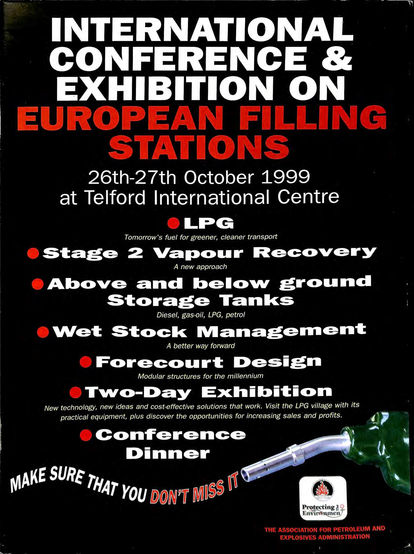
The Conference information is enclosed in this Bulletin invitincr members to attend both the Exhibition and b Conference at Telford. The Conference entry will be free providing members pre-book their places otherwise a £20 fee will be payable for registration on the day.
GRPTANKS MAKING COMEBACK?
A number of major oil companies are re-examining their policy on storage tank construction and are once again looking at GRP tanks as an option for their tank replacement programme. This change has come about mainly by improvements in GRP technology. which has enabled a more cost-effective construction for double skin tanks to be utilised. This in tum has enabled double skin GRP tanks to be as competitive as double skin steel.
KEN WILCOX
The Ken Wilcox & Associates has just published a new document "Recommended Practice for Inspecting Buried Lined Steel Tanks Using a Video Camera (PDF)"" copies are available from their web site alono with a CD ROM on Leak b Detection 2000. Web site http://www.kwaleak.com
INTERNATIONAL CORROSION CONFERENCE 28 SEPTEMBER 1999
CAPE TOWN, SOUTH AFRICA
Risk Assessment Workshop on underground storage tanks
An international conference on corrosion of underground storage tanb will he held in CapL' Town on 28 Septemhl'r
1999 with speakers from the USA, Europe and South Africa. The Conference will concentrate on the reasons for corrosion of tanks; the methods of preventing it and also ways of risk assessing and arresting corrosion on existing buried tanks. Details of the conference can be obtained from Steve Holt Tel 0027 214037443 e-mail steve.holt@caltex.co.za
DRAFT EUROPEAN STANDARDS OUT FOR PUBLIC COMMENT
A number of European standards are out for public comment at the moment affecting the service stations they are:-
pr EN 13616 Overfill prevention devices for static tanks for liquid petroleum fuels.
pr EN 13617-1 Petrol filling stations Part 1: Construction and performance of dispensers.
Pr EN 13617-2 Constmction and performance of safe breaks for use on dispensers.
Copies of these documents can be obtained from BSI. Tel 0181 996 9001, e-mail info@bsi.org.uk and comments should be with BSI by the end of September 1999.
TOTAL OIL PETROL LEAK GOES UNCHECKED FOR A YEAR!
Total Oil were called to answer the questions of Council officials following a leak of SO.OOO litres of petrol from a garage in St Alb;ns. Three senior representatives faced the irate councillors to answer questions on why they were so slow to act over a leak which was leaving the tank at over 33% of the sales from the unleaded tank. Jeff Attwood d . . . . ,. d the committee that trector of petrol retmlmcr 1111orme 0 I 1998 80% was lost although the loss was apparent throug 1 · I · e·U" The general between November and February t us Y ' · 1 I d " ·own to an a arnung manager explained that the losses 1a 01 H t ted tll·it d d ·h t down e s a , rate before the tank was teste an s u . · d' .,,1·plill"irv b ·ub1ect to ' J seven people involved had een s J • llad been or nr111a cre1 , action and two includmg the sem 'd ;nvironmental dismissed. Ken Chichester the safetyd ;n nd petrol on the . 1 t tI ey ha 1 ou officer told the cmmmttee t ia 1. d . tile chalk around h I , the site an m water table 22 meters e OVI · • hwe been at risk. . d that residents may ' the site. He recogmse · t' fo ilino to take proper . . . d tl e 'ompany rn a o Councillors cnt1C1se 1 c the residents. In the . d I· " informat10n action and then e aymo tl e local Member ol • , 1 · . I ·ere 111c1dent 1 altermath ol t 11s me regime 1s made k' tank-testmg Parliament 1s as ·mg •1 f II t ks t'1 be tested. mandatory or a an · '
IN INCIDENT
LPG nowered vehick in France A hre mvolvmg d t , 1 1 h F., 1 11 fire fiohters when tht' LPl 1 tank hemg tack Cl Y lt:I l e 1 ·1 "\"l"'I\' hti 1111' 11 n six firt'
exp lll l't st: ·i.: ; ,,. · ·
LPG CAR TANK EXPLODES
One IIll' hg.hlt'I
lost a leg and another a hand in the incident. This fire brought to light the difference in safety standards between conversions on vehicles that use LPG as a duel fuel with petrol. It would seem that 90,000 of the 120,000 cars equipped to run on LPG in France do not have a pressure relief valve fitted and they to could explode in a fire situation. The UK has around 4000 vehicles currently running on LPG and certainly the later conversions should all have a pressure relief valve fitted in the LPG tank situated in the vehicle boot.
SPLIT DELIVERIES ON VAPOUR RECOVERY
A test was carried out at a site in London with stage lb vapour recovery, simulating a split delivery from a road tanker compartment, with dipping from the orifice on top of the road tank.
The following observations on the test were made:-
• When the road tanker arrived at the site and the dip tube cap was removed, a spurt of vapour from pressurisation of the compartment occurred. There was no monitoring equipment in place at this time.
ADMINISTRATOR'S NOTES
North West Branch
Mr Bob Conlin of Fairbank Environmental has replaced Mr Harry Reid as Branch Secretary for the North West Branch. Bob will be arranging a branch AGM as soon has he is able.
Members of the branch are encouraged to support this meeting and to offer Bob as much support as they can and also, to participate in the affairs of the branch.
Mr Conlin can be contacted on 01695 51775.
Mailing to the APEA
Will members and companies please note, that any mail sent to our old address at Hadleigh is being returned to the sender, as the Post Office is no longer redirecting our mail.
1999 Conference and Exhibition Telford
'
The arrangements for this year's Conference and are in hand and any companies who would like mformation on exhibiting at the show should contact Mr C K. h mg t on 01992 451494 for a booking form. The stand area is 33% larger than last year, at the same cost.
, As is a topical subject, we are planning to have an LPG Village' within the Exhibition with several companies who specialist in equipment for this product participating in the show
Again, the Association is holding the Annual Conference Dmner on the evening of Tuesday, 26th October 1999 at 7.30pm with complimentary pre-Dinne; nnks, followed by Dinner at 8pm. The cost for a table of 10 persons is £350.00 +VAT, or £35.00 +VAT per individual.
The Dinner is concluded with an excellent and humorous after-Dinner speaker.
Companies or individuals who would like to make a reservation for the Dinner can obtain a booking form from the Association Administrator.
Q.F.S.M.
Petre ileum Officer Station Officer MICK NORZON. West Midlands Fire Service was recently awarded the Queen's hn: ')en ice Medal in the Queen ·s Birthday Honours List. Our ··u11gra1ula11ons lo Mick on this prestigious award.
• The delivery was set up with a constant monitoring vapour detector placed 450mm from the dip opening.
• The delivery was started and the dip tube opened and dip readings were taken to simulate a split delivery. There were no vapour readings during this period.
• As soon as the delivery stopped the vapour detector sounded off and vapour was actually seen around the dip opening. The dip opening was closed, but the detectors continued alarming.
• A series of tests involving other compartments were made and similar results were obtained. Although when another compartment was opened during a delivery or immediately after a split vapour will be emitted from the dip tube.
Conclusion
This test was not conclusive as it proved that the road tanker was not vapour tight. A bellows leaked and several of the manlids did not appear to be vapour tight when pressure built up in the road tanker.
It demonstrated that if a split delivery is to be permitted safely then the split delivery should be permitted first. Entry into further compartments is likely to allow vapour to escape.
A further test should be arranged with a vapour tight road tanker to verify these observations.
PUMPS & TANKS (SHOREHAM) LTD Reg. Co. 763619 (now liquidated)
TIA Independent Pump Services Reg. Bus. name 2201941
A thank you goes out to all the sincere and genuine members of APEA who sent me so many wonde1ful cards and best wishes during my 4 months of numerous life threatening operations in 1993.
Sadly my remarkable recovery was not in time to prevent my extraordinary dismissal from and the Joss of my own company whilst I was still recovering locally in Dorking. Surrey.
William R Adams
.I
'i9
International Conference & Exhibition 26th and 27th October 1999
Telford International Centre, Telford, Shropshire, UK
CONFERENCE PROGRAMME
Tuesday 26th October 1999
10.00 Exhibition Opens and Registration of Delegates
10.55 Conference opens with welcome address by Mr Ian Taylor APEA Chairman
Session 1 chaired by Mr Anton Martiniussen
11.00 Environmental Benefit of LPG
Mr Tom Fidell: Director General, Liquefied Petroleum Gas Association
11.30 Automotive LPG Retail
Mr Paddy Kilmartin, Managing Director, Flogas UK Ltd
Time to visit the Exhibition
Session 2 chaired by Mr Jamie Thompson
14.00 Above Ground Storage "USA Practice"
Mr Wayne Geyer, Steel Tank Institute of America
14.30 Case Study for Above Ground Petrol Tanks at a Public Filling Station
Mr Rory Hennessy, Petroleum and Fire Safety Officer, Tesco Stores Ltd
17.00 Close of Exhibition and Day one.
19.30 Pre-Dinner Drinks in Exhibition.
20.00 Conference Dinner
Wednesday 27th October 1999
09.00 Exhibition opens and Registration of Delegates
Session 3 chaired by Mr Tony Jenner
10.30 New Approach to Stage 2 Vapour Recovery
Mr Steve Dean, Product Manager, Hasstech, Division of OPW Inc
11.00 Modular Forecourt Design for the Millennium
Mr Tony Fox, Managing Director, Highcross Canopies Ltd
11.30 Wetstock Management -A Better Way Forward
Bob Conlin, Fairbanks Environmental Ltd
16.30 Close of Conference and Exhibition
HSE PUBLISHES GUIDANCE FOR USERS OF LIQUEFIED PETROLEUM GAS
The Health and Safety Executive (HSE) has produced two new information sheets on halth and safety aimed at small scale users of liquefied petroleum gas (LPG) in small bulk tanks and cylinders.
LPG (propane or butane) readily evaporates into a gas. It has no smell, although it will normally have an odour added to help detect leaks. When mixed with air, the gas can bum or explode when it meets a source of ignition. It is stored in pressurised tanks to keep it liquefied.
'Use of LPG in small bulk tanks' (Chemical Sheet No 4) contains basic information on the hazards of this colourless liquid. It details precautions needed as well as what to do in the case of a leak or fire as well as giving guidance on deliveries.
The sheet complements the detailed guidance produced by the LP Gas Association in their code of practice one part one and their recent published code of practice one part four for buried/mounded LPG vessels.
'Small-scale use of LPG in cylinders' (Chemical Sheet No 5) also contains basic information on the hazards of LPG, leaks, deliveries and precautions required in the area where the cylinders are stored or used. The sheet complements the detailed guidance produced by the LP Gas Association in their code of practice number seven.
Both these information sheets should be useful to the small user who normally relies on their supplier for advice.
Copies of 'Use of LPG in small bulk tanks' Chemical Sheet No 4 and Small-scale use of LPG in cylinders' Chemical Sheet no 5 are available free of charge from HSE Books, tel: Priced pubhcations are also available from good booksellers.
, " L. tel · 0541 545500, P
60
ENVIRON SOLD
By agreement dated May 25th, 1999 Kiva Corporation, a Pennsylvania holding company, acquired the assets of Universal Epsco Inc. (UEI) located in Atlanta, Georgia. Kiva is also the owner of Environ Products Inc., Environ Europe, LTD and Interon Corporation. Effective immediately the company will operate under the new name of Universal Dispenser Corporation (UDC).
The acquisition of UEI by Kvia offers many advantages to the petroleum equipment industry. UEI's advanced dispenser technology of incorporating fiber optics and integrated color touch screen displays can now be maximized by Kiva's innovation, manufacturing and marketing capabilities.
UEI's manufacturing facility will be relocated within the next thirty days to a 100,000 square foot manufacturing facility located in Morgantown, PA. A number of UEI's key design and manufacturing personnel shall also relocate to Pennsylvania from Georgia.
Universal Dispenser Corporation will be issuing new product literature and price lists by September 1st, 1999. Until that time it will continue to honor the prices contained in UEI's product price list and dispensers will eventually be available from Plymouth.
Some personnel changes that have occurred in the UK:-
Nick Hugh (formerly of Tokheim/Schlumberger) has JOmed Environ as Sales & Marketing Manager.
Gertrude Chaville has recently joined us in Customer Services and Doreen Pooley as Technical Support Engineer.
Officially, Environ Europe Limited has now been renamed Kiva International Limited however the company will continue to trade under the familiar Environ This change of name reflects the increasing volume of mternational business outside mainland Europe.
In view of past problems with water ingress to the tank chambers, it was agreed to install units (Fibrelite Elite) which themselves could be subjected to a vacuum test once all pipework and duct entries to the chambers had been completed.
Again, both the Petroleum Officer and myself witnessed these tests and four of the chambers failed. Tanks 1 and 3 had leaking suction flanges, which the pipework contractor remedied on site. Tanks 6 and 7 both required new tank lid gaskets, which were subsequently fitted and the chambers retested satisfactorily.
The chambers themselves and all pipework and duct entries were tested sound from the beginning and a further set of tests will take place when the gauging system has been installed, probably just prior to site opening.
The failures found on tanks chambers 1, 3, 6 and 7 should have been discovered during the manufacturer's factory test.
Since the tanks are supplied with a certificate stating that they have been satisfactorily tested at the factory, it is common for most authorities to accept this, thus obviating, in their view, the need for further site testing.
If we had not installed the above chamber system (Fibrelite Elite) and applied the vacuum testing procedure, these leaks would have gone undetected, which could have lead to possible petroleum vapours escaping into the chambers and water entering the tank compartments if the chambers were leaking, which inferior units, or those installed without due diligence often do!
In conclusion, because of the above experiences, it is my view that it is unwise to solely rely upon any tank manufacturer's certificate of soundness and that tests of the interstitial spaces and tank lids should always be undertaken.
Tom Armstrong Armstrong & Associates Dear Editor,
Bulletin Praise
Dear Editor.
_In view of the recent experiences regarding tanks 'failing· test, I thought it prudent to share this experience with your readers.
The tanks were supplied by a major U.K. manufacturer as a of their successful tender. Upon delivery. a cei1I11cate stating that they had been satisfactorily tested at their factory accompanied them.
Once the tanks were placed in the excavation. both the Pelroleum Officer and myself witnessed a test on each "" 1l1lpart111ent\ 1nter-;1i1ial ..,pace. all tests proving to he '><
When a media journal reaches the level of interest. and stimulation that the Bulletin provides. then I consider it worthwhile forwarding a message of gratitude to those who participate in its formulation.
A periodical which is not afraid to sight cases of prosecutions, publish exciting and sometimes controversial ai1icles and keep us up to date with legislation. all makes for a good read.
The Bulletin power is obviously recognised by the plethora of adve11isers. and its newsworthiness proven by the wealth of contributions.
I trust the forthcoming proposab to make environmental health responsible for petroleum retail sites does not lead to the demise of the considerable expertise currently a\ ailahle.
Letters
'' 'rn I
or jeopardise the quality of this journal, and perhaps the Editor will comment upon this!
May you have another 40 years on and on and on
Kevin Dawson Environmental Consultant
Editors note: Watch this space!
DURAPIPE ANNOUNCES LAUNCH OF PETROL-LINE
XTRA
Durapipe S&LP has launched Petrol-Line Xtra, the advanced pipework system that offers immeasurable permeation with maximum integrity, an addition to the Petrol-Line product range that also includes Petrol-Line Plus and Vent Plus.
Petrol-Line Xtra is designed for all below-ground forecourt applications. Its two-layer construction an outer layer of polyethylene and an inner layer of continuously bonded polyamide provides tensile strength, flexibility and superb resistance to permeation. It is ERA tested, certificated to the Institute of Petroleum specifications and manufactured under a quality management programme conforming to BS EN ISO 9001.
Announcing this addition to the range, Dennis O'Dea, Marketing Manager, Forecourt Systems, said, "Petrol-Line Xtra is the natural result of Durapipe's commitment to continuous development. The range has evolved in line with industry needs and is a powe1ful example of what can be achieved when manufacturers and customers work together."
A filling station near Manchester, undergoing a refurbishment programme, is the first in the UK to install a Petrol-Line Xtra system. Serving each of its 4-pump islands f1:om submersible pumps, the 01iginal single skin steel pipework is being replaced by Petrol-Line Xtra with secondary containment and a monitoring system , while Petrol-Line Plus has been used for the installation of a Stacre 2 vapour_ recovery system. The benefits of the new compet1t1ve pricing and dependable service, were crucial factors in gaining the contract.
_Dennis O ' Dea commented 'The expertise Durapipe has built up over the years is passed on to our customers every time. This new range is desi crned to offer our customers a bigger and better choice of quality , high pe1formance pipework."
Petrol-Line Xtra has a complementary rancre of low voltacre electrofusion · · · 1 ° .
_ o J0111t111g t iat has the same properties ot stiength, flex1b1hty mid_ safety in service. The fuel-proof system is _ava!lable 111 either single or secondary contained conf1gurat1on for suction or pres sure applications
Durapipe S&LP is th e larg es t co mpany within Glynwed Pipe Sy stem s Ltd and spec iali ses in th e manufacture of hicrh integ rity pipework sys te ms for th e UK and inarkets
Prosecution
A licensee was prosecuted by Essex Trading Standards for failure to appoint a competent person to oversee a petrol delivery, and failing to ensure that the competent person had received adequate training.
On 14th September 1998 the defendant Dovercourt Motor Company Limited at Colchester had a delivery of fuel. The only trained employees were not on site so a kiosk operator was told to carry out the duties of the competent person overseeing the delivery. Having recorded the contents of each tank, she failed to notice that the 4 star tank contained too much so when the delivery was beincr made b the tank ove1filled resulting fuel discharged through the air separator vent of a petrol pump and onto the forecomt.
The Comt was told the incident was fmtunately contained due to the prompt action of the tanker driver and only 100 litres of fuel were lost but petroleum spirit is a volatile product and the failure could have resulted in a more serious problem.
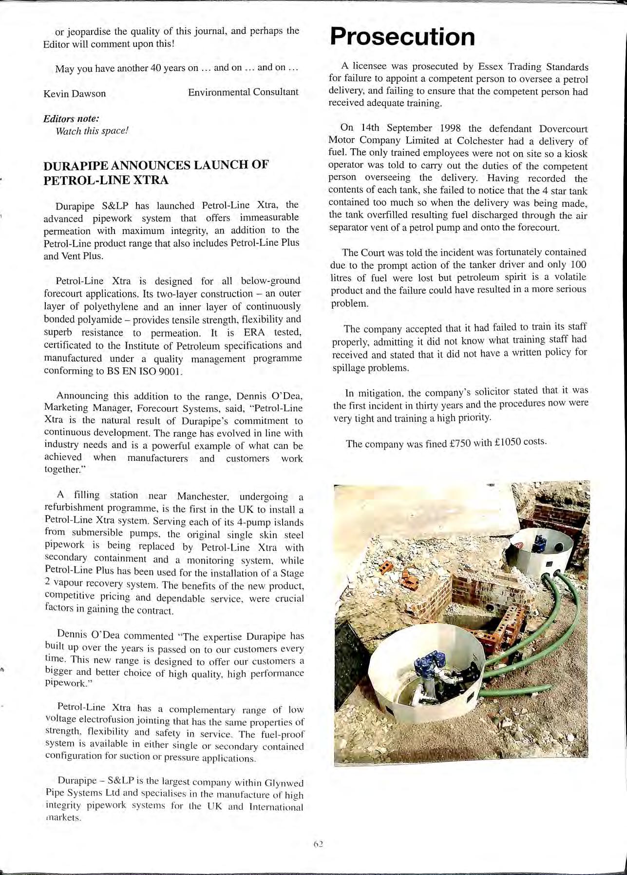
The company accepted that it had failed to train its staff properly, admitting it did not know what training staff had received and stated that it did not have a w1itten policy for spillage problems .
In mitigation, the company's solicitor stated that it was the first incident in thirty years and the procedures now were very tight and training a high priority.
The company was fined £750 with £1050 costs.
6 2
PINTO WELCOMES NEW CHAIRMAN Elf's
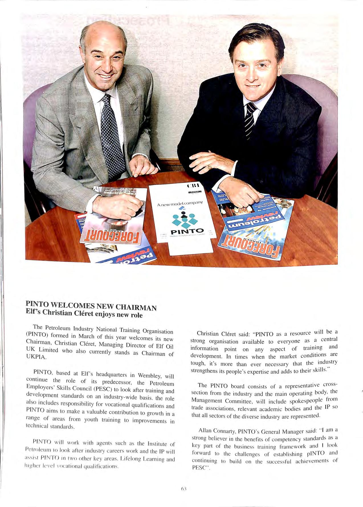
Christian Cleret
enjoys new role
The Petroleum Industry National Training Organi sa tion (PINTO) form ed in March of thi s year welcomes its new Chairman , Chri stian Cleret, Managing Direc tor of Elf Oil UK Limjted who also c urrently stands as Chairm a n of UKPIA.
PINTO , base d at Elf 's headquarte rs in Wembley, will co ntinue the rol e of its predece ssor, the Petroleum Employers' Skill s Counci l (PES C) to loo k after training an d deve lo pm e nt standard s on an indu stry- w ide basis. the ro le a lso in c lud es respons ibilit y for vocat iona l qu alifi cati ons a nd PI NTO aim s to make a va lu a bl e co ntribution to grow th in a range of area s fr o m youth trainin g to impro ve ments in tec hni cal s ta nd a rd s
P INT O w ill wo rk w ith ag e nts such as the In stitute of Pe tro le um to look afte r in d ustry ca reers wo rk a ncl the IP will ass i-. t PI NTO in two ot he r key a reas. Life long Learnin g and h1g he 1· l eve l vocati o nal c.iua lifi cat io ns
strong organi sation avai la ble inform ation point on any
tati ve cross- The PINTO board cons ists of a repre se n ' h ·atin a body, t e sec tion from th e indu stry a nd th e mam opei' "' f . k eo pl e rom Manageme nt Comm ittee , will mclud e spo es p p . d. id the I so trade as socrntJons, relevant academic bo 1es 31 th at al l sec tor s of th e di ve rse indu stry a re repre se nted.
d· --1 am a
All an Co nn arty, PINTO ' s Genera l Manage1 s,u · st ron a be li eve r 1n th e ben efits of co mp eten cy s' "' f k 'tnd I look key part of the bu sin es s tra1111ng r a mewo1 ' . . "h. a INTO a nd f-orwa rd to th e cha ll e nges ot es ta bl1 s 1ne P co ntinuin g to build on the succe ss ful ac hi eve me nt s of PESC".
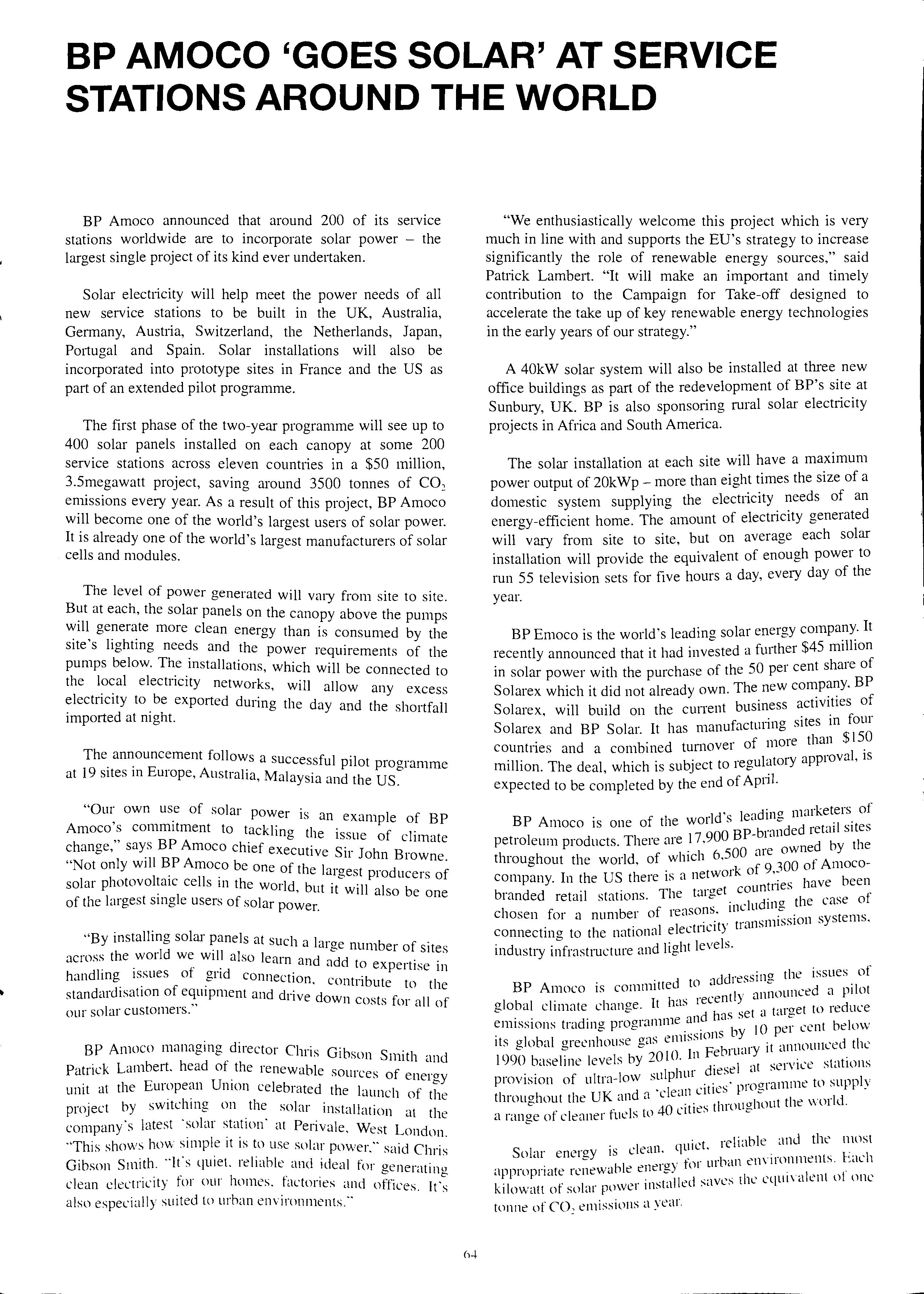
BP AMOCO 'GOES SOLAR' AT SERVICE STATIONS AROUND THE WORLD
BP Amoco announced that around 200 of its service stations worldwide are to incorporate solar power the largest single project of its kind ever undertaken.
Solar electricity will help meet the power needs of all new service stations to be built in the UK, Australia, Germany, Austria, Switzerland, the Netherlands, Japan, Portugal and Spain. Solar installations will also be incorporated into prototype sites in France and the US as part of an extended pilot programme.
The first phase of the two-year programme will see up to 400 solar panels installed on each canopy at some 200 service stations across eleven countries in a $50 million, 3.5megawatt project, saving around 3500 tonnes of C0 2 emissions every year. As a result of this project, BP Amoco will become one of the world's largest users of solar power. It is already one of the world's largest manufacturers of solar cells and modules.
The level of power generated will vary from site to site. at each, the solar panels on the canopy above the pumps ":111. more clean energy than is consumed by the site s hghtmg needs and the power requirements of the pumps below. The installations, which will be connected to the electricity networks, will allow any excess electnc1ty to. be exported dming the day and the shortfall imported at mght.
The announcement follows a successful pi"l t . . . o programme at 19 sites m Europe, Austraha, Malaysia and the US.
own us_e of solar power is an example of BP Amoco s commitment to tackling the · f 1 ,, issue o c unate change, says BP Amoco chief executive s11 John B " ·11 B rowne. Not only wt P Amoco be one of the Jai·gest . d f . . p10 ucers o solar photovoltaic cells m the world bttt ·t 11 1 b • t w1 a so e one of the largest smgle users of solar power.
"By installing solar panels at such a lai·ge b f . num er o sites across the world we will also learn and add t . . ' o expertise 111 handhng issues of gnd connection cont .b t . . . · n u e to the standard1sat1on of eqmpment and drive down costs " . II f our solar customers. ,, • IOI a O
BP Amoco managing director Chris Gibson Smith and Patrick Lambert. head of the renewable sot11·ces f . . o energy umt at the European Umon celebrated the launch of tl 1· re project by sw1tc 1mg on the solar installation at the company's latest ·solar station· at Peri vale. West London "'This shows how simple it is to use solar power." said Gibson Smith. ··ifs quiet. reliahle and ideal for generatino clean electricity for our homes. factories and offices. also especially suited to urhan environments."
"We enthusiastically welcome this project which is very much in line with and supports the EU's strategy to increase significantly the role of renewable energy sources," said Patrick Lambert. "It will make an important and timely contribution to the Campaign for Take-off designed to accelerate the take up of key renewable energy technologies in the early years of our strategy."
A 40kW solar system will also be installed at three new office buildings as part of the redevelopment of BP's site at Sunbury, UK. BP is also sponsoring rural solar electricity projects in Africa and South America.
The solar installation at each site will have a maximum power output of 20kWp more than eight times the size of a domestic system supplying the electricity needs of an energy-efficient home. The amount of electricity generated will vary from site to site, but on average each solar installation will provide the equivalent of enough power to run 55 television sets for five hours a day, every day of the year.
BP Emoco is the world's leading solar energy company. It recently announced that it had inv;sted a further $45 million in solar power with the purchase of the 50 per cent share of Solarex which it did not already own. The new company. BP . . b · ess activities of Solarex will bmld on the current usin ' · · in four Solarex and BP Solar. It has manufactunng sites . f nore than $150 countnes and a combined tumove1 o 1 1 million. The deal, which is subject to regulatory approva ' is expected to be completed by the end of April.
d' 1 dincr marketers of BP Amoco is one of the worl s retail sites petroleum products. There ai·e 17,900 BP ed by the . h 6 500 are own throughout the world, of whic ' . _ f 9 '100 of Amococompany. In the US there is a netwoi k 0 ·: have been TI t· ·cret countnes branded retail stat10ns. 1e Hie d" the case of f ons mclu mg chosen for a number o 1eas · ·ssion systems connectincr to the national electricity transnu · 0 1· J t I vels industry mfrastructure and 1g 1 e ·
ddressing the issues of BP Amoco is com1111tted to a 1 • an;wunced a pilot I b I . h It Iris recent y ' g o a chmate c ange. '· 1 1 1 t·ircret to reduce e and ms se ' ' "' em1ss10ns tradmg progranun . . b 10 per cent below l b I 1 . as en11ss10ns y its g o a green 10use g.· b .. ·y it ·mnounced the . 1 b ?O I0 In Fe I uat , 1990 baselme leve s Y · d" 1 ·it service stations l ·ulphur iese ' prov1s1on of ultra- ow s , rocrramme to supply h UK d a ·cJe·m cttlt::S P ct roughout the an ' '. 1 . ohout the world a rancre of cleaner fuels to 40 cities t uoucc
· 't reliable and the most Solar energy 1s clean. quit:: · , 1; 1 ·cr, for urban env11onm1::nts. ,,\L 1 ·ipproprnte renewable enetc-) '. ' . ,. . ·t·ill,d saves the cqut\'alent ol nnc kilowatt ot solar powc1 ms • 1: tonne of co" emissions a year.
! 'I I I, I I PERIVALE-WESTLONDON BP GOES SOLAR I INSTALLING SOLAR PANELS
v 1111 ••••
6 6
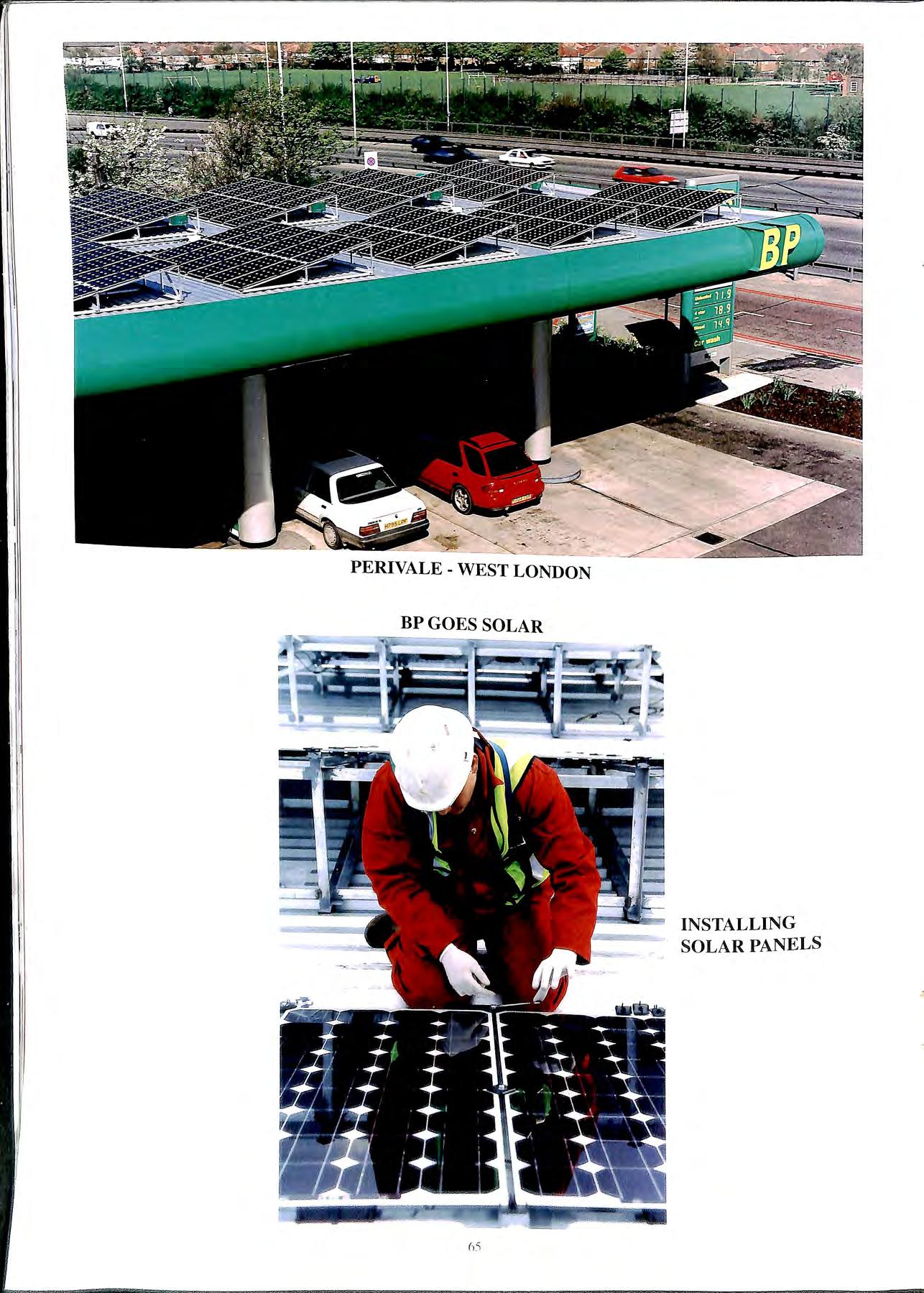
ART BOROFF OF HEALY SYSTEMS AND TONY JENNER OF FORECOURT ENGINEERING SENT IN THESE PHOTOGRAPHS OF THIS SERVICE STATION IN NEW HAMPSHIRE USA. ALTHOUGH NO LONGER USED FOR PETROL THE BENNET ECO PUMPS ARE KEPT IMMACULATE WITH A PRICE TAG OF 40 CENTS A GALLON!
APEA Guidance on Storage and Dispensing of LPG as an Automotive Fuel at a Petrol Station
1. Introduction
LPG used for motor vehicles is generally known as Autogas and is becoming recognised as one of the alternative engine fuels which are considered to have environmental benefits and there is likely to be a rise in its use at petrol filling stations.
The petroleum licensing authority under the Petroleum (Consolidation) Act 1928 can issue conditions to a petroleum licence covering the safe keeping of petroleum spirit. Where LPG is stored and dispensed on a licensed filling station, approval of such an installation is normally required under conditions of that licence.
The following guidance is issued to cover standards for storing and dispensing LPG at petrol filling stations.
2. Storage
Tanks should be designed, constructed and installed to a recognised pressure vessel code (e.g. BS 5500) and fitted with appropriate pressure relief, excess flow valves and other safety devices in accordance with LP Gas Association Code of Practice 1 Part 1.
On a petrol filling station the positioning of above ground storage tanks is important from a public safety view point and the distances in table 1 of this guidance note should be observed.
Storage tanks should be placed in a compound to prevent uncontrolled public access. The compound should:-
• provide adequate ventilation (e.g. open mesh fencing);
• be at least I .8m high;
• be a minimum of 3m from the storage tank;
• have a minimum of 2 means of exit from the compound, outward opening and operable from inside;
• not be placed under overhead power cables.
All above ground tanks should be situated to provide means of access for fire-fighting vehicles. In addition adequate water supplies to maintain an application rate according to the risk for at least 60 minutes, these may be taken from the public water supply (e.g. hydrants).
Means should be provided to isolate the tank, pump and dispenser from each other in the case of fire, or other emergency situation. This may he achieved by the provision of automatic solenoid valves situated in the compound and at the dispenser.
Where the tanks are situated in such a position that they lllay he sub1ect to vehicle impact damage, then suitable pn 1lecl 1rn1 should he provided (e.g. crash harriers or h,1lhrd<.J
It may also be necessary in some cases for the storage to be placed underground if the distance conditions cannot be met or sloping ground towards off site risks makes this undesirable.
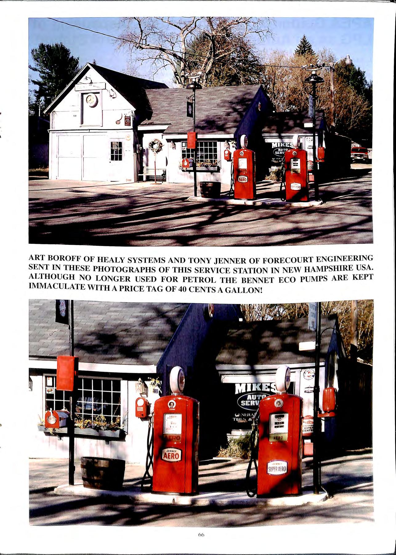
Table 1
LPG tank size Minimum separation distance from above ground vessels
Maximum LPG Cap Total quantify of Buildings, boundary With Fire capacity of (tonnes) tanks in one or fixed ignition Wall tank compound source (metres) (litres) (litres) (metres)
<500 <0.25 1500 2.5 0.3 500 to 2500 0.25 to I.I 7500 3 1.5 2500to9000 I.I to4 27500 7.5 4 9000 to 52000 4to 30 52000 15 II
Note
• Tanks should be placed a mm1mum of 1m between vessels or l .5m for those over 9000 litres capacity.
• For tanks up to 2500 litres the fire wall shall be as high as the top of the tank and may form part of the site boundary, or building wall. The wall needs to be of 60 minutes fire resistant construction when the building is in residential use.
3.
67
Separation
on the
separation
components of
filling
2. Minimum Separation Distances (Distances are as seen in plan view) Storage Storage LPG pump LPG vehicle dispenser being filled 1. LPG Storage vessel 2. Storage vessel fillin11: connection 3. LPG Pump 4. LPG Disnenser 5. Vehicle bein11 filled 6. U/G Petrol tank Manhole with fill connPction 7. U/G Petrol tank manhole without Fill connection 8. Above ground tank for liquids <65°C flash point 9. Remote petrol tank fill connections I0. Petrol tank vents 11. Petrol dispensers explosion protected Diesel dispensers Vessel Nil Nil but Ilnl beneath tank 0.Sm 3m 7.Sm 3m Vessel Fill Connection Nil Nil Im 3m 7.5m 3m Nil hut not beneath tank Nil Nil I.Sm 7.5m 3m As COP Part I Tahle of Safety Distances for flammable liquids 7.5111 7.5m 7.501 7.5m 7.5m 7.5111 7.5m 7.5111 7.5111 D:..:.r-=:ot::::cc"'·te"'d+--:'..'3r!..'.n._+-_-:'.'..'..'3 111·->-- Ni I 12. Parked Cars 6m 6m I 5111 0.5m 3m I.Orn 3m Nil I.Sm Nil Nil 7.5m Nil 3m Nil 7.5111 !\ill 7.5m_ -1'fil_ Nil Nil Nil Nil Nil Nil or 'cpara1101i Ji,li.Jnl'l' 111 -·--·-·-------r-_Tahkj__ I l Site Boundary 01 ,l..'.p;1rat1on dhtann: 111 fobll' I 11 lc,, As Table I Buildings 4. 2:'im I trom : wh1dl' I fill romt !
Distances Guidance
minimum
distances between
a
station is shown in Table 2 below: Table
4. Pumps
Pumps should be situated in the tank compound but not underneath the storage vessel. They should be suitable for Zone 1 use.
5. Pipelines
Steel pipelines used for LPG liquid and vapour lines should be to BS 3601 and when installed underground shall be fully welded and suitably protected against corrosion. This is normally by cathodic protection or by a suitable coating, (galvanising is not considered suitable).
6. Dispensers
There are at present no recognised construction standards for LPG dispensers, therefore construction details, electrical components and safety features should be submitted by the manufacturer with C.E. marking. A copy of the Hazard Area Classification for LPG dispensers is shown below.
e Dispensers may be placed on the island adjacent to a petrol dispenser and should be protected against impact by the provision of a crash barrier or bollards surrounding the dispenser.
e Each dispenser hose should be provided with a safe break connection with a secure mounting point to avoid damage to the installation in the event of a drive-off.
• The vapour return line from the dispenser to the tank should be provided with a non return valve.
• All should be securely mounted on to the pump island.
e All dispensers should be capable f b . . 1 d o emg 1so ate from the mstallatJon for servicing d 1 b . . . . . . · an remova y the mstallat10n of 1solat1on valves.
e Dispensers should be sited whe th b viewed and supervised from there conso e pos1t1on.
7. Electrical Wiring to Pumps and n·1spensers
Two emergency switches are req · . d . une on all filhng stations:
1. at the control point in the sale b .1d. h f s u1 mg; and 2. on t e 01ecou1t 111 a position readil members of the ge . I . y accessible to nern pubhc.
The electrical circuits to the LPG ·I ould be arranoed so th·tt h pump and dispenser s 1 e ' on t e ope t" f switch on the filling station. the LPG ia ion emergency also the petrol pumps' dispensers are. and Le ectncally isolated.
These should only be capable of b" . . . . l emg 1eset from mside the conso e ,11 ed.
A means of communication from th -, e console pos1t1on to the LPCi d1spense1 should he provided ,-. 1 1 . . . · \Id t 1e oudspeak.er system used t01 pet10l pumps.
8. Fire Extinguishers
Dr\· imwdcr fire extinguishers rn111 11Ivino with BS L'N , e · .-: _, not less than %.g and suitable for LPCI fires with a rating of at least 21 A and I:-OR should he <I\ ai lahll' al strategic
9. Notices
To be displayed on the storage vessels or on the compound:
Highly Flammable Propane No Smoking
To be displayed at the dispenser: Liquefied Petroleum Gas Extremely Flammable Switch off Engine Apply Handbrake No Smoking No Naked Lights Switch off Mobile Phones
10. Operations
The authorisation for use of any LPG dispenser should only be carried out by the person in charge of the self service console.
The operation of the dispenser once authorised be via a button on the dispenser which must be m dunng operation of the pump. Releasing the button will stop the flow of LPG.
LPG tanker deliveries shall not be permitted at the same time as a petrol tanker delivery.
11. Training
"d d h d h ld be provi e at t e A wntten emergency proce ure s ou · d · the danoers of site and all staff should be fully trame m 0 ak · the case of any LPG and on what act10n to t e m . S ff · d dispensing. ta emergency during storage, delivery an training records should be kept on site.
12. Authorities you may need to consult
The Planning Authority . r the Environmental The Health & Safety Executive 0 Health Authority.
13. Bibliography d". ensing of LPG as Detailed guidance on storage d the following an automotive fuel may be. obt,une h docu 111ent is the bibliography. Listed along1de eac . d . . . . . . y be obtame · orga111sat10n from which it ma
Title Code of Practice 1 Bulk LPG Storage at Fixed Installations
Part I Design & Installation
Part 3 Periodic Inspection and Testing Code of Practice 11 Autogas Installations Code of Practice 22
Publications Available From G Association LP as I LPG Piping Systems Design & Installation . . , ·11rrc11t at thl' tilll<' c•/ /'llh/1, ·e111011 The uho\"l' 1111h/icaf/Oll.I' llll 1 o( this U11id1/l/CI' Note
I l
6X
I I, I AREA CLASSIFICATION - DISPENSERS LPG Dispenser Computer Hydraulic Components 250 mm I 4m C=:::J Zone 2 Hazardous Area Zone 1 Hazardous Area 1 m above highest liquid joint 4m FIG.I TYPICAL L.P.G. DISPENSER INSTALLATION WITH HYDRAULIC COMPONENTS AND HEAD MOUNTED DIRECTLY INSIDE DISPENSER HOUSING LPG Dispenser Computer Vapour Barrier Hydraulic Components 250 mm 4m y Zone 2 Hazardous Area Zone 1 Hazardous Area 1 m above highest liquid joint 4m FIG .2 TYPI CAL LP.G D IS PENSER INSTALLAT ION WITH HYDRAULIC COMPONENTS AND HEAD MOUNTED DIREC TLY INSIDE DISPENSER HOUSI NG BUT SEPARATED BY A VAPOUR BARRIER ALL COMPONENTS IN HAZARDOUS AREAS SHALL HAVE EX PLOSIO N PROTECTION. IN TH E ABSENCE OF ANY STANDA RD , A SAFETY ASSESSMENT BY B.A.S.E.E.F.A. WILL BE ACCEPTED.
Explosives Atmospheres Directive
By A. Jacobs, Gilbarco Ltd
The UK Regulations implementing the ATEX Directive has now been with us for 3 years. Although still not mandatory until 2003 there are advantages to be gained by manufacturers obtaining compliance earlier rather than later. The main advantage being that Ex approval has only to be obtained once within the European Union (EU), rather than having to gain approval in all of the individual Country Members.
In order to understand ATEX, it is necessary to have an understanding of 'New Approach Directives'. These are essentially the laws of the EU (European Union). The UK, of course, has now been a member of the EU for 27 years. In 1985, the EU ministers were concerned about the proliferation of national technical standards and saw this as a barrier to trade, which was impeding the process of European integration. They came up with the concept of a 'Single Market' or 'Internal Market' with no barriers to trade. There was to be a new approach to technical harmonisation to achieve the objective of free movement of goods. Hence 'New approach Directives' were devised. These directives contain 'Essential Requirements' which tend to be written in general terms and as such are not prescriptive. In order to comply with these directives it is necessary to meet the 'Essential Requirements'. Harmonised European standards give a presumption of conformity to the essential requirements, and when available can give the clearest and most straightforward route to compliance. Products meeting these Essential Requirements should carry 'CE' marking to indicate compliance to all relevant applicable directives.
For a manufacturer, compliance to these directives opens up a much larger Market place with common technical requirements the 'Single Market'. This currently consists of the I 5 members of the EU which also includes the 'European Economic Area' (EEA) and therefore adds Norway, Iceland and Liechtenstein, hence making a total of 18 countries. (The EEA includes both the EU and EFTA countries) Bearing in mind the countries applying for membership of European Union, the market place open to manufacturers is very large indeed and it becomes clear that CE marking and compliance to these directives can give enormous advantages.
Examples of new approach directives that are already in force and applicable to many types of products are:-
Machinery Directive 1995. applies to machines
EMC 1996. applies to most electrical equipment
Low Voltage Directive 1997. relates to electrical safety.
Others include the Pressure Equipment Directive. Personal Protective Equipment directive. Packaging and Waste Directive and what is known as a I 18a directive
which concerns the protection of workers in Explosive Atmosphere.
The ATEX Directive itself was implemented into UK Law by 'The Equipment and Protective Systems Intended for use in Potentially Explosive Atmospheres Regulations 1996' (S.I. 1996/192). There is currently a transition period during which compliance is optional. The transition period runs out in July 2003, at which point it becomes mandatory.
Useful sources of information on ATEX, and indeed, other directives can be obtained from various sources. These include the DTI, who have produced guidance notes on the UK Regulations. The DTI hotline number is 0117 944 4888. The DTI also has a very informative Web site on www.dti.gov.uk. There is also expected shortly to be some guidelines issued by the ATEX Standing Committee, which will look at the directive in more detail. Another very useful source of information is a Trade Association relevant to your industry these can often obtain information and draft documents before they are put into the public domain. The full text of the ATEX Directive was published in the Official Journal of the European Communities No. LlOO, dated 19 April 1994.
ATEX applies to 'Products'. These include Equipment, Protective Systems, Safety Devices, and components. It applies to new products placed onto the EU market for the first time. Used or secondhand products first placed on the EU market prior to ATEX do not need to comply when sold on. Also reconditioned or reconfigured products do not_hav: to comply with ATEX unless they have been 'substantially modified. Clearly the term 'substantially' can important and it would be wise for anyone :c modifications to seek the advice of a Notified Bo Y i ey are in any doubt.
. 1 aal terms, is the An important document, in e"' sed mainly , . ' Th. document is u Declaration of Conforilllty · is rtain important b . d t contain ce y enforcement agencies an mus infonnation. This includes:-
• Name of Manufacturer e Description of the Equipment.
• DAii relevant provisions fulfilled.
imber of the Notified Body and e Name. 1dent1ficat10n Ill e examination certificate the number of the EC-typ (where appropriate).
. d . other standards that have e Reference to Harmomse 01 been used.
EU Directives which haw been e Reference to other applied.
• Identification of the signatory.
-
94/9/EC
ATEX
70
ATEX also requires 'CE' marking. This is used to indicate that the product is in compliance with all applicable directives. Quite often this marking will appear on approvals plate on the equipment itself. It should include:-
• 'CE' Marking
• Specific Marking ® II 2GT3
• Year of manufacture
• Name and address of Manufacturer
• Series of type
• Serial number
• Identification number of Notified Body Responsible for surveillance.
It is necessary to decide the appropriate route to compliance for your product. This would entail making the following decisions:-
e Does ATEX apply?
Is the equipment used in an explosive atmosphere? Does it have its own potential source of ignition?
• Which Group is applicable?
Group 1 - Mining
Group 2 - Places other than Mines, likely to become endangered by explosive atmospheres.
• Which Category is applicable?
Category 1 = Very High Level of protection
Category 2 = High Level of Protection
Category 3 =Normal Level of Protection
category of product.
As previously stated, new approach directives contain 'Essential Requirements'. Some examples of essential requirements from ATEX are listed below
• Design should include analysis of possible operating faults to preclude dangerous situations Risk Analysis.
• Must cope with foreseeable surrounding area conditions
• Marking of products is defined
• Instructions to be provided installation/use/training etc translated into the language of the member state where used.
• Safe Opening.
• Potential ignition sources must not occur (sparks, flames, high temps etc)
• Overheating caused by friction should be prevented at the design stage.
• Surface temperatures should not exceed the stated maximum.
• Equipment must be fitted with suitable cable and conduit entries.
• Software controlled equipment take account of risks in the program.
(Zone 0) (Zone 1) (Zone 2)
(Note: Risk Assessment should be carried out and this may help in defining the Category)
Once the group and the category of the product has been ascertained it should become clearer as to what a manufacturer has to do to demonstrate that his product meets the requirements of the directive. The diagram below gives a visual indication of the way to compliance for the 3 categories of equipment:-
Clearly category I equipment, being the highest risk, requires the highest level of protection and therefore has the strictest conformity assessment regime. This will involve third party certification for both the type examination of the design of the product, and third party involvement during the production phase. On the other hand category 3 products. being the lowest risk. only requires normal levels of protection. Therefore there is no need for third party mvolvement and a manufacturer can self certify that his product meets the requirement of the directive.
Each of the unshaded boxes in the confr>rmity assessment diagram. represents a particular annex in the directive itself. 10 those annexes. is advised in order to uruln'iland the parlicular quality modules applicable to a
As can be seen, these are written in very general terms, and it may be more appropriate to use a Harmonised standard which is applicable to your particular product if one is available.
Lastly as a case study, we will briefly look at the steps necessary when assessing a fuel dispenser to ATEX
1. Does ATEX apply _
Is a fuel dispenser used in an explosive atmosphere? Yes. Does it have it's own potential source of ignition? Yes.
Therefore clearly ATEX applies to Fuel Dispensers.
2. Which category is applicable certainly not category (Zone 0), so either category 2 or category 3.
There is still some debate over this, so to play safe in this case study, we will assume category 2.
3. Looking at the earlier diagram on conformity assessment. and particularly at the category 2 requirements. the first question we reach is 'is a .fiiel di.ipenser an Internal Comhustion Engine or electrical equipment " 1
Since a fuel dispenser would normally contain some electrical equipment. the answer is Yes. Therefore we need 'EC type' examination. This would involve the
\ : I II
71
• No Harmonised Standard yet for Fuel Dispensers , Draft CEN Standard can be used as ' Best Practice ' Guidelines with other ' Essential Requirements ' ad ded
e Approval Drawings to be Components Tabulation!fypical Schematics & Joints.
• Instructions to be generated
produced. Zoning/ Wiring/Hydraulic
e Risk Assessment (FMEA) required (analysis of possi ble operating faults).
• Requirements of Electric al Safety of machines to be addressed.
As part of this type examination , there are a number of type approva l tests that need to be carried out. These will include the following
• Maximum Service pressure 3.5 bar
• Overpressure Test at 14 b ar no catastrophic damag e.
• Overpressure Test at 5.25 b ar no leakage
• Fl oa t Test at 14 bar
• Vapour recovery pipe work to be pres sure te sted to !Obar.
• Vapour Barrier tests (IP54/P67 )
• Seal & Gasket test soak for I OOOhrs in fuel/pre ss ure test at 5.25 bar.
• E lec tric cable te sts Solvent test/lmpact te st/Be nd te st/Voltage tes t
e Di spenser Stability te st pull tes t via th e hose at 2000N.
lt is also a requirem e nt th at durin o the pi·oduct· 1 "" ion p iase, a numb er of routme te sts sho uld be co nducted on eac h eq uipm en t manufactured th ese are show n below
e Earth Bonding Test Inj ec t 10 Amps/Measure vo lt age drop
e In s ul at ion Re sista nce tes t 500v de/> I Mohm
e Fun ctional te st Fu nct ions correct ly Specification
e Hyd raulic leak test. Th e re shall be no leaks.
accord in g to Manu fac ture rs
directive itself. Essentially it involves the manufacturer conducting 'end of production line' testing and final inspection to en sure each product is manufactured according to the design tha t is approved
It is interesting to note that we hav e third party involvement in both th e design phase and the production phase. The third parties are referred to as 'Notified Bodies' It is not necessary for the Notified Body used during th e design phase to be th e same one as used during the production phase. If a manufacturer already ha s a quality system b as ed on IS09001 or IS09002, the 'Product QA' module should not pose too many problems.
Finally, after drawin g up a ' Declaration of Conformity' and with the Fuel Dispe nser suitably ' CE ' marked it sho uld hopefully now be in conformity to the ATEX Directive. It therefore should find no b arriers to trade in all of the EEA countries.
T he qu a li ty modul e c hose n fo r the prod uc tion phase is ' Product QA Thi s is descr ibed in A nn ex Vll o f the ATEX
following:-
72
Ecostak introduces 'Blackberry Technology
by Graham Wilson Marketing Director of UET Ltd., Combs Tannery, Stowmarket, U.K.
UET is a U.K. company which, with its French subsidiary, has in the last four years developed 'ECOSTAK', a system incorporating a 'blackberry technology' which allows the detection of thin films of petrol, diesel oil and other hydrocarbons to be achieved. Based on a simple principle, the system can have many uses in monitoring both double and single-skinnned storage installations, and for being combined with other equipment in an integrated approach to pollution prevention.
Leakage from single skinned systems cannot generally be prevented from reaching the environment and, whether wetstock analysis or external sensors in monitoring wells are used for monitoring them, the environment will normally have been polluted before any leakage is detected.
The prevention of any leakage must obviously be preferable to its detection after a pollution has already occurred and the only means of achieving this is through the adoption not only of double-skinned tanks and but also of double-skinned pipework, with leakage containments at all points where a double-skin is otherwise not achievable.
The monitoring of the interstitial spaces of double-walled tanks and pipes using pressurised inert gas or a vacuum is theoretically a better solution than those involving their monitoring by liquids or directly by sensors, as the use of inert gas or vacuums for monitoring avoids the possibility of polluting the environment. However, there are those who would argue that the costs involved in installing and maintaining liquid or sensor-monitored double-walled systems make these a more economic and practical alternative.
These arguments, as to which double-skinned solution may be appropriate, should also take into account any data following risk assessment of a site, but they may be somewhat academic as, despite the rationalising of distribution networks and the upgrading of retail outlets throughout Europe, the replacement of every old singlewal Jed underground storage tank and section of singleskinned pipework will not be achieved 'overnight'.
Ecostak is being introduced against this background where there is a need to minimise the frequency and the scale of pollutions from single-skinned storage systems and optimise the effectiveness of the less costly double-skin solutions.
The Ecostak sensor has been specifically designed to enable detection of liquid-phase hydrocarbons floating in thin films on water, for example in sumps and other leakage containments or on groundwater ; but it is also well-suited for the monitoring of interstitial spaces and other leakage containments which should normally be dry. It can function equally well where a centimetre or two of petrol or diesel has accumulated in a low point in a normally dry containment, or where a half millimetre film is floating on a variable-level water surface. It can monitor water level while simultaneously effecting its principal function of detecting any petrol or diesel oil which may be present.
The length of a sensor, and other details may be adjusted during manufacture to enable it to be used for a particular purpose. Sensors can be provided for double-skin storage systems both for direct use in monitoring interstitial spaces. where there is suitable access, and equally for use in sumps or containments into which the interstitial spaces of doubleskinned systems may drain.
Although it is equally effective for monitoring double skinned systems the Ecostak sensor was originally conceived as a purpose-built 'ultimate' solution for use in monitoring wells.
During a groundwater pollution by petrol or diesel oil the pollutant product tends to spread out on the water in a 'plume', displacing water underneath it so that. unless the smrnunding ground material is particularly impermeable. any localised increase in the level of the liquids is very small. As the thickness of the plume is usually least at its leading edge, a sensor needs to be designed so that it will detect a film when it is as thin as possible. as it may take days, weeks. or months for the thickness of the plume to increase to a higher detection threshold.
!' 11 ,J ,, j'I l.i ! 'I A new
·
ingredient for leak prevention systems
The Ecostak sensor was conceived to fulfil this groundwater monitoring function , capable of beino installed in monitming wells as small as 501m 11 diameter, th: wells are strategically located and can be provided with drainage trenches to lead floating product to them so as to increase the efficiency and reduce the potential response time of the overall detection system. The sensor permits early detection of thin films of free product on groundwater inespective of normal variations in the level of the watertable
Wetstock management systems provide the current solution to leak detection which is normally included at sites where either part or all of the storage installation is singleskinned. Their advantage is that they can often monitor the storage system, tanks and pipework together, on a global basis. When double-skinned installations are not in use. the best wetstock management systems are likely to give the quickest indication of major leakages, although the many problems related to accurately reconciling theoretical and actual stock levels impose limits on their effectiveness. A tenth of a percentage Jo ss of product at a high throughput in s tallation still adds up. over a period of time. to a substantial pollution problem. The usefuln ess of wetstock management systems in helping to redu ce the frequency and extent of soil and groundwater pollution s from se rvice s tation s, while pro v iding management information. is undeniabl e. but they alone are not capable nf providing a re liabl e mea ns of leak detection und e r all circumstances
Certain of th e principal s uppli e rs nf we tstock manag e ment syste m s acknow ledg e the nee d for s uppl e mentar y equipm e nt by offe rin g se nsor s for us e 111
monitoring wells. However, monitoring well sensors like Ecostak need to be capable of detecting films of the order of O.Smm in order to detect a pollution problem at an early stage.
Ecostak groundwater sensors , like all other sensors in an Ecostak system, are connected to ' Sensor Head' monitoring units which communicate with a ' System Controller ' by low power radio telemetry. The System Controller is designed with an inte1face by which it can communicate alarms and data either direct to a remote monitoring centre or to a local PC or other unit. This enables inventory control and wetstock analysis to be combined with Ecostack and any other leak detection equipment at the site in an integrated approach to pollution prevention.
Like the System Controller, the 'Sensor Head' unit s which monitor the sensors incorporate mjcroprocessor technology ; they are battery powered and, as no hcu-d wiring is necessary, they are easily retro-fitted. Th e use of software in the 'Sensor Heads ' as well as by th e S ys te m Controller allows th e control system to be adapted not only to a range of different detection situations. but also to se nsors incorporating different principle s to those of th e stand<lrd Ecostak se nsor syste m for exa mpl e. th e h e ad e r tank s of liquid-monitored double-skinned tanks ca n be monitored e ith e r by float -s witch or imp ed e nc e-based senso rs. and a numb er of different solution s ca n be prnpos e d for th e monitoring of int e rcep tor tanks. A va ri e ty l1l se nsnrs on a s ite. of dif'ferent ty pes. ca n th erefo re be includ e d 111 ,1 mi xe d sensor leak pre ve ntion a nd detection sys tt'lll
View.from a tank where groundwater is monitored by a drainage trench and three well sensors. Note the 'se nsor head' on the steps. By courtesy of Southern Counties Fuels. Warming/id, Sussex.
E11q
t's
11i11
ref n1 4'"1-lJ 7 N5 77 Fu 1 01'1'"1-lJ6 77 600
WHAT IT IS AND WHAT IS DOES
ECOSTAK is a system which includes three principal modules
e Intrinsically safe sensors, for monitoring wells and other applications, which detect thin films of petrol, diesel and similar hydrocarbons floating on water , such as those encountered in the early stages of leakage of a stored product. The sensors are not sensitive to water containing dissolved pollutants , such as may be found at some sites where there is no current leakage problem.
e A self-checking monitoring system, using low power radio, which (not only) can monitor UET's sensors (but also) and other intrinsically safe detection or monitoring devices. The near absence of cable requirements makes the system easy to retro- fit at existing installations and improves safety.
e A compact software-based control system, allowing stand-alone operation of the Ecostak system or its use in combination with inventory control and other leak detection equipment.
The Ecostak Sensor was conceived for detecting thin film s of hydrocarbon s on water, (even) where the level of water is variable. Typical examples of such situations are s ump s and other leakage containments where water and leaked product may either or both be present and monitoring well s
Th e sen sor is made up of a number of cylindrical spacers, whi c h are mounted together on a vertical spindle as a column s upporting a cylind1ical weight. These spacers, which resemble blackberrie s, are stable in water but di sinteg rate in the pres ence of li q uid hydrocarbon s
Th e co lumn is in sta ll e d so that it is partly immersed in the wa te r to be mo nit o red. The wate r can ri se or fall within the se nso rs ra nge , w hil e the SUiface o f the water al ways rem ain s in co ntac t w ith a s pace r If eve n a very thin film of h yd roca rb o n is prese nt o n th e wate r s urfac e , the s pac er at that leve l w ill p rog ress ive ly di sintegra te and th e column will sho rt e n . T hi s sho rte nin g (w hi c h) is detec ted by dev ices wi thin the vert ica l s pin d le , triggerin g an a larm s ig nal.
Th e le ngt h o f the c o lumn c a n be up to 160 e ms o r mo re to c a te r fo r fl uc tuat io ns o f th e wate r leve l, a ncl s pec ia ll y d e 1g ned float .., w itc hes a re prov ided so that leve l re.., u lr 11 the wat e r leve l r ise.., or fa ll s to a leve l a pproa chin g
the limits of the sensor's length.
UET's Control System is made up of two principle elements, Sensor Heads, to one of which each sensor in the system is connected, and the System Controller which monitors anything up to thirty Sensor Heads at a site.
The Sensor Head is a self-checking low-energy batterypowered monitoring unit for use with intrinsically safe device s It uses coded radio signals to communicate with the System Main Controller, and incorporates microprocessor technology to analyse and respond to signals from the sensor it is monitoring or from its Sy stem Controller. Not only can it monitor UET' s own sensors , but it can (be adapted to) handle other detection or monitoring equipment.
The Sy stem Main Controller continuously monitors all of the Sen so r Head s on a site , and generates vi s ua l and audibl e alarm s when any alarm signal is received It verifie s daily that th e radi o link with each o f the Sen sor Head s is fun cti onin g correc tly. [t c an (and ) acts as an in te1fac e whereby all re leve nt dat a ca n be co mmuni c at ed e ith er to a ce ntral mo nito rin g se rvice or input to an integ rat ed leak and po llu tion preve nti o n sys te m w hi c h mi g ht in corp ora te in ve nto ry moni to rin g and ot he r d etec ti o n dev ices
I·
7)
TESTING TIMES AHEAD
Interactive Testing of Stage 1 B by Petroman Environmental Services Ltd.
As we are all aware, the initial phase for the implementation of Stage lB (the system) has now been completed, with a few exceptions. A substantial number of these installations have been fitted with little regard to the site's compatibility with vapour recovery. Compounding this situation, some of these installations have been constructed in such a manner that it is quite possible that they are not working at all, let alone meeting legislative requirements.
Although Stage 1B is simple in concept, it can be relatively complex in its operation. To ensure that the system works correctly, its components must be in sound working condition and be properly located on the site in relation to one another.
It would appear that many Stage 1B systems are being "tested" by just replacement of pressure/vacuum valves and or vapour termination connection points. This does not test Stage lB, but is merely a risk limitation exercise of two components that form a small part of the whole system. This procedure is not cost effective (especially if the components are not faulty), and offers little value to the site operator with regard to testing the system as a whole.
During the operation of Stage IB, high volumes of vapour are being both pushed and drawn through the system, back to the delivery tanker, (more so with higher temperature product being delivered). The design and position on the forecourt of all 1B dictates the amount of residual vapour remammg w1thm the system after a delivery. This residue will collect in the system and eventually will prevent the system from working efficiently. This situation could begin right from the first delivery, whilst other systems may well maintain their efficiency for much longer periods.
Although this of testing was originally developed by Petroman Envtronmental Services Ltd. for a different purpose, it does meet all of the current legislative requirements for testing Stage 1B systems. In addition, it can be used to test a site without Stage I B for compatibility with vapour recovery, in order to determine if any forecourt work is necessary prior to an installation. The testing procedure can also be used for helping diagnose faults on sites with particular vapour recovery problems.
The Petroman Interactive Testing system allows all components of a Stage lB system to be tested. This includes the drop tube sealing (within each storage tank), each vent pipe. each fill pipe and all .cam covers or ca.ps, pressure vacuum valve and the site vapou.r termmatJ?n connection. Testing is unde1taken as the same time as the site receives a delivery of fuel. However, there is only a minimal increase of just a few minutes to the actual delivery time of a tanker being off loaded.
This form of testing is NOT a precision testing system and makes no representation of being one.
One of the obstacles to overcome in designing a testing system for all sites is that no two sites are the same. Therefore
each individual Stage 1B system is particular only to that site, and its operation is dictated by the conditions of that site. In addition, deliveries and stock levels at the time of each test will always differ, as well as the off-loading sequences. The Petroman Interactive testing system takes this into account.
The delivery tanker dictates the performance or efficiency of a Stage 1B system. If a poorly designed system is connected to a delivery tanker with properly working vapour recovery equipment, then the chances of a failure in the system are minimal. Conversely, with the same tanker delivery to a site with a system in poor condition, this will substantially increase the chances of a failure.
Taking these factors into consideration, this method of testing has to be undertaken with the delivery tanker on the site at the time of the test, and the results from the test monitored against the delivery tanker's own efficiency.
The testina kit comprises flow meters for measuring the fill pipes and0cam covers. A flow meter and control valve are placed in the vapour recovery return line, and two pressure ·d f th e One measures the aauges are attached each s1 e o es · pressure within the sites system, and the other, !0 cated on the tanker side of the valve is used to determme performance of the delivery tanker (displaying the vacuum m the tanker compartment created by the delivery).
Once again. this is NOT a precision test of the tankers sealing qualities. but is a reflection of t?e workmg condition of the tankers vapour recov e1y eqmpment and thereby its influence on the sites Stage lB system.
The flow control valve and the main flow _meter, is sure the vanous flow operated by the test en omeer to mea • 0 This data 1s then rates and pressures w1thm the system. collect4ed at certain intervals throughout the test use?
By foilowmo a n°1d assess the efficiency of the sites system. 0 0 f Pour are momtored method of protocol flow rates o va . ' · h the sealino of each drop through each vent pipe together wit · e. tube (fill pipe in storage tank), with any 1ec01ded. The vacuum side of the pressure/vacuum is at the strut of the test procedure and the pressure side the delivery. The condition of the site vapour term111at10n is then checked at the end of the test. Once this has been completed. then all the components of the system have been individually. Finally, with a nominal pressure locked. mto the system, the whole Stage I B is monitored for a fe':'' mmutes to check for any pressure drop. which would 111d1cate the presence of a vapour leak somewhere in the system.
By using this form of testing. it is only necessary to usl' one test engineer. The whole system is tt:·sted and the data '" used as a comparison for the following year. testing the. -.itl' again using the same procedure. By comparing test data trom one year against another. the engineer will be ahk tu determine the rate at which the system i-. dt'L'lirnng Ill efficiency and the presence of fault-. that 1rngh1 ha\ l' developed since the last test.
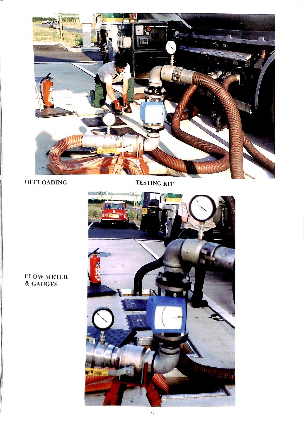
OFFLOADING FLOW METER & GAUGES TESTING KIT 77
It is possible that those faults, although not a hindrance to the system at that time, could possibly become so later on. It is therefore important that the site operator is made aware of this situation, allowing him to plan for maintenance to be carried out on the system. In this way, the operator can plan his repair and maintenance budget and prevent problems from actually occurring on site rather than having to cure them once they have happened.
Maintaining Testing Quality and Control
This will be a harder operation than the testing itself, but maintaining the integrity of the testing system will be paramount. We are appointing a number of well-established companies, all of whom have a reputation for high standards of workmanship and operation as well as the ability to run and maintain an efficient administration.
These companies will be issued licences by which they will undertake to operate the testing procedures to a rigid protocol. Petroman is working towards achieving ISO 9002 Quality Assurance, and therefore each engineer will be subject to regular checks and monitoring and all testing will equally be subject to strict quality checks.
Each test engineer will be thoroughly trained in the principles of Stage lB together with the testing procedure, completion of the documentation and troubleshooting. As part of their accreditation, they will be required to carry out a minimum number of tests in a period, ensuring continuity and familiarity of testing, as well as helping to maintain their expe1ience and due diligence.
Provided the testing procedure has been correctly adhered to, the testing engineer will analyse the test data, (comparing these with previous test results if available) and determine whether the site can be issued with a pass certificate. If the data i1:dicates syst:m has deteriorated in efficiency over time, but 1s still working safely, then the engineer can still auth_orise a pass certificate for the site. Alternatively, he may decide that he must authorise the issue of a conditional pass certificate. This would be subject to say minor works or repairs being undertaken by the site within a st1-ict time frame, (such as replacing a faulty PN valve) and that work being subsequently checked or confirmed.
If the test results prove that there is a serious problem on the site, then the engineer would immediately issue to notices. The first will be a warning notice to the site, giving details of the problem or potential setious risk, and this notice will have to be signed by the site operator at the time of the test as their acknowledgement of the condition. A second warning notice will simultaneously be issued to the delivery tanker driver and for. m1d this will be_ a precaution against further deltvenes bemg sent to the site before essential works are completed.
The enaineer will. in addition. authorise the issue of a formal fail certificate to the site. along with instructions for works to be undertaken within a strict time frame. However. serious faults. along with essential major repairs will have to be a matter of discussion between the site operator and the engineer. with the risk factors associated with those faults being fully assessed .A complete re-test v.ill haw to he undertaken.
Upon receipt of all completed test documentation from
individual test engineers, Petroman Environmental Services Ltd. will be responsible for actually issuing each site test certificate. In addition we will hold all information of each test site on a datebase that will be accessible to all test engineers.
Petroman Environmental Services Ltd will also be carrying out random testing on test sites to assess whether the protocol is being maintained and observed, along with the interpretation of test results. All engineers will be regularly updated with a news letter containing latest information or details on testing, to ensure that they are always fully briefed and advised of their own standards as well as assisting them with problem solving associated with the testing.
Petroman Environmental Services Ltd will also be operating an independent blue print testing service, only for new or refurbished sites. This will be to test a newly installed system, ensuring that it meets its required operating standards as well as collecting the data against which all future testing can be assessed. In addition we will undertake testing on sites that have particular difficulties or when a specific situation has arisen that is beyond the standard testing protocol. Our appointed engineers will handle all other testing.
Since carrying out testing with this method'. we established that there are many sites that will reqmre modifications to their system as well as further work. on some of the components on the site. With over _l 00 sites tested, one of the most striking statistics we have discovered is the surprisingly large number of delivery tankers not holding or maintaining vacuum. A significant nu_mber of tankers we have found with faulty interlock mechamsms and their valves not being actuated to allow the vehicles vapour recov cry system to operate con-ectly.
The delivery tanker produces up to -20-mbar pressure across the sites vapour recovery system, and this increases during a test to within + 1O mbar pressure at the end of a delivery. This provides a good working range for the system to operate within, as opposed to some systems operating as high as +30 mbar at the end of a delivery.
An inefficient system induces higher operational pressures and therefore puts components under greater stress. This in tum promotes more serious problems for the site, such as blowbacks and difficult draining of delivery hoses.
This testing system has been designed to offer the operator a standard of testing that will improve the design and installation of Stage l B so that they can meet their environmental responsibilities. It will also assist in ensuring that the deliveries are safely completed for their benefit and that of their supplier.
All certification we hope will offer the authorities the confidence to know that each system has been fully lL'sted to a standard that is beyond their current requirenwnts.
For further information on this subjel·t. contact Petrnman Em ironnwntal Sen il·es Ltcl. 01223 Yi."i 177.
Stage l B testing. patent applied for Tl'St111g Prntornl (Testing pnll'L'dure \is thl' l'llj1\ right ol l\'troman l.td.
7X
DRIP STOP diesel nozzle
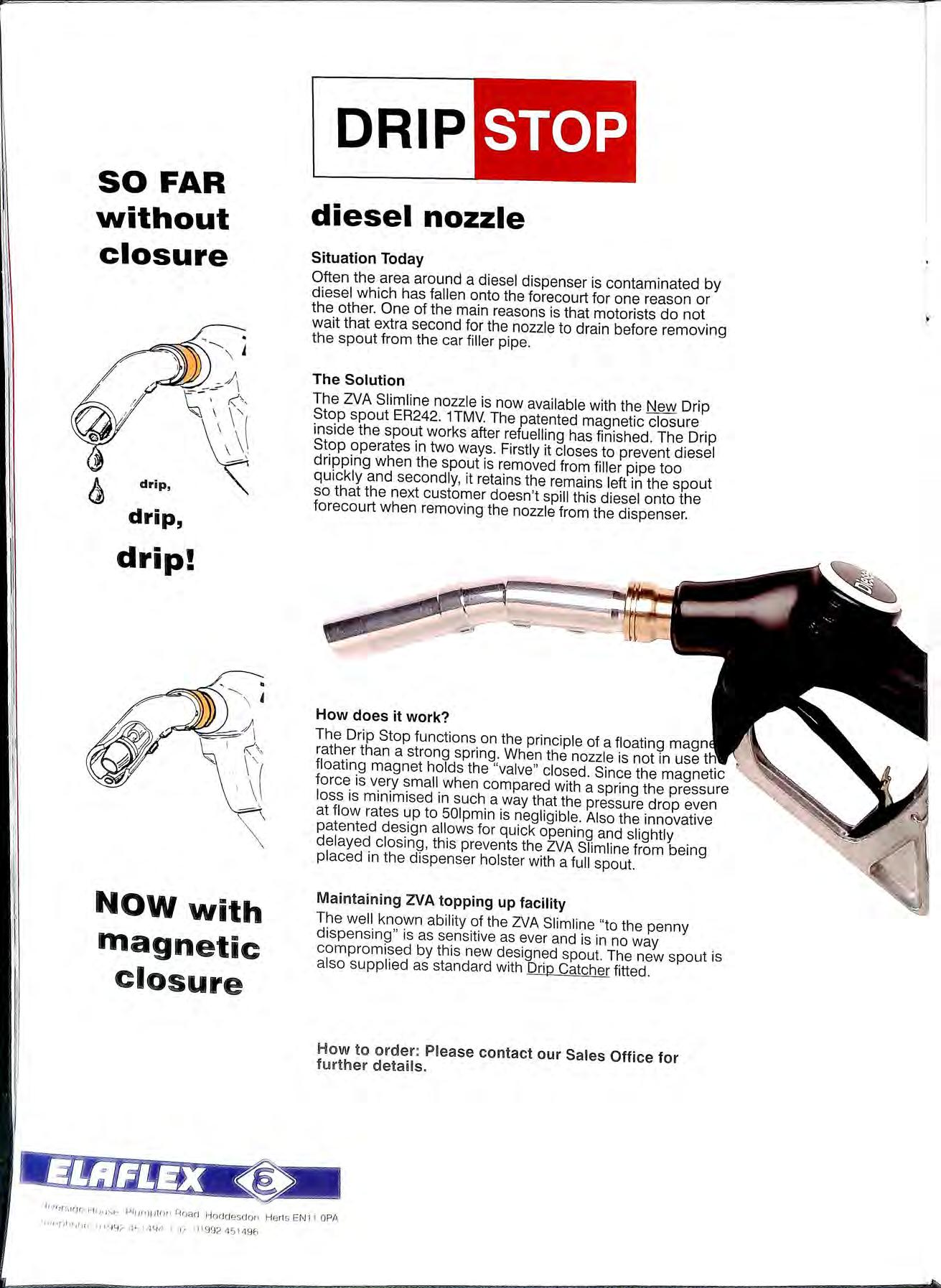
Situation Today
Often the area around a diesel dispenser is contaminated by diesel which has fallen onto the forecourt for one reason or the other. One of the main reasons is that motorists do not wait that extra second for the nozzle to drain before removing the spout from the car filler pipe
The Solution
The Z.VA Slimline nozzle is now available with the New Drip Stop spout ER242 1TMV. The patented magnetic closure inside the spout works after refuelling has finished. The Dnp Stop operates in two ways. Firstly it closes to prevent diesel dripping when the spout is removed from filler pipe too quickly and secondly, it retains the remains left in the spout so that the next customer doesn 't spill this diesel onto the forecourt when removing the nozzle from the dispenser.
How does it work?
The Drip Stop functions on the principle of a floating magn rather than a strong spring When the nozzle is not in use tH floating magnet holds the "valve " closed. Since the magnetic force is very small when compared with a spring the pressure loss is minimised in such a way that the pressure drop even at flow rates up to 501pmin is negligible. Also the innovative patented design allows for quick opening and slightly delayed closing , this prevents the l:JA Slimline from being placed in the dispenser holster with a full spout.
Ma intaining ZVA topping up facility
The well known ability of the ZVA Slimline "to the penny dispensing" is as sensitive as ever and is in no way compromised by this new designed spout. The new spout is also supplied as standard with Drip Catcher fitted How
etai l s
SO FAR without closure drip, drip! Now with magnetic closure
· livr,,51CJr, Hriu5e, Pl 11rnplo 1• Roa cJ H o aa es don H erl s 1 1 OPA 1 '"'ff-' (Jl1ru1p t 11y 4 ,::.. •J'1 i 4Y4 1-:=t;ir fl 1992451496
to order : Please contact our Sales Office for f urt h er d

Tan k Gauging a nd Leak D etection \ I I ' 40 60 / -20 so'"" % ,, -;;;;;;, -· 'TankGuard' 2001 a @ e HHl HL iI. E UROGAUGE Lllve! AIJrms ck lu.t J_ I .. @ I ••• TEST REFILL MUTE LIQUID FILLED AND DRY AIR PRESSURE LEAK DETECTION SYSTEMS FOR STEEL OR GRP DOUBLE SKIN TANKS. LEAK DETECTION SYSTEMS FOR DOUBLE CONTAINMENT PIPES , ACCESS CHAMBERS AND PUMP ISLAND SUMPS. " PROLEVEL " TANK GAUGING SYSTEM FOR UP TO 16 TANKS. PC AND MODEM COMPATIBLE FOR LOCAL AND REMOTE MONITORING. "TANKGUARD' ' LOW COST ELECTRONIC TANK GAUGING SYSTEM. " TANKMATE 160" SELF POWERED TANK GAUGE FOR DIESEL AND GAS OIL INTERCEPTOR AND OIL SEPARATOR LEVEL ALARM SYSTEMS BS EN ISO 9001 QUALITY ASSURANCE. ALL SYSTEMS MEET RELEVANT SAFETY STANDARDS. EEx ia /IC FOR ZONE 0 AND EEx ib /IC FOR ZONES 1 AND 2 . .. .. .. . .. .. .. ... . ... . .. .. .. . . . ....... . .. . .. .. . ...... Why not talk to the specia/ists:EUROGAUGE COMPANY LIMITED IMBERHORNE LANE , EAST GRINSTEAD , WEST SUSSEX RH19 1RF Tel: 01342 323641 Fax: 01342 315513 cf G site Quality services for today's forecourt HIGH QUALITY RE-IMAGING OF PUMPS, CANOPIES, SHOPS POLE SIGN ERECTION & MODIFICATION PLANNED IMAGE MAINTENANCE PROGRAMMES PUMPS &EQUIPMENT= HAULAGE, STORAGE & DISTRIBUTI ON Valley Road, Cinderford, Gloucester GL 14 2NY Telephone: 0594 826364 Fax: 0594 822807 __J

You deserve h the best, wysettle for less ... THE LEADER IN PETROLEUM TANK MANUFACTURE Including: • SUCTION PIPES • FILL PIPES • OVERFLOW PREVENTION • CHAMBERS • GROUND COVERS, and much more ...


_.. SPECIALIST ELECTRICAL ENGINEERS & CONTRACTORS TO THE PETROLEUM INDUSTRY n1tEla rrirn! Comrnaon ' A m1ci nrio1J MEMBER OF A.P.E.A Nationa l Inspection Cou ncil !or Elect rical Installat ion Contractrng REG ISTERED MEMBER • •1cE1c APPROVED CONTRACTOR e Closed-circuit TV e Fire Alarms & Emergency Lightning e Planned Maintenance • Inspection & Testing • Forecourt Earthing Systems C IC LS S& HEAD OFFICE: PROJECT HOUSE• THE DRIVE• WORTHING• WEST SUSSEX• BN11 SLL TEL: 01903 700321 FAX: 01903 507498 BY TOTAL CONTAINMENT low cost, flexible solutions for all fuel pipework IPUIRfFl!EIET fOR!ECOURT S!E!RV ij C!ES S;?Q London Ro ad , W est Thurrock, Grays, Essex RM20 3BE Te l () 1 708 8 6 393 1 Ext 2 19 Fax 0 1708 864140 So le UI< Distributor • Most flexible pipework system • No underground joints • Suitable for alternative fuels "' High flow rates • Competitive prices l>U"Al'\:EEi f"iJREGtJUR"f SElWICES LTO TOTAL CONTAINMENT

The NIPS PETROFUSE System offers the total solution the industry has been asking for. Consider the credentials of NIPS Petrofuse and Fusamatic. • FULLY WELDED SYSTEM • CORROSION-RESIST ANT • NON-PERMEABLE • NON-BRITTLE e TRACEABLE PIPE JOINTING • LOW COST • RIGID SYSTEM • DETECTABLE PIPELINE The product range consists of a range of pipe, fittings and tooling in the size range 50mm , 63mm, 90mm, I IOmm The pipe outside diameters are based upon BS 5556 and ISO 161 I I. All of the pipe and fittings are black pigmented Black has been carefully selected as it affords the best and most cost effective solution against environmental UV degradation, that can occur with polymers.The polymer has also been carefully selected to provide the 30 year design life required by the specifications of the industry. F us AMA TDC c W oRlD LEA DING AUTOMATHC ELECTROfUSDON SYSTIEM
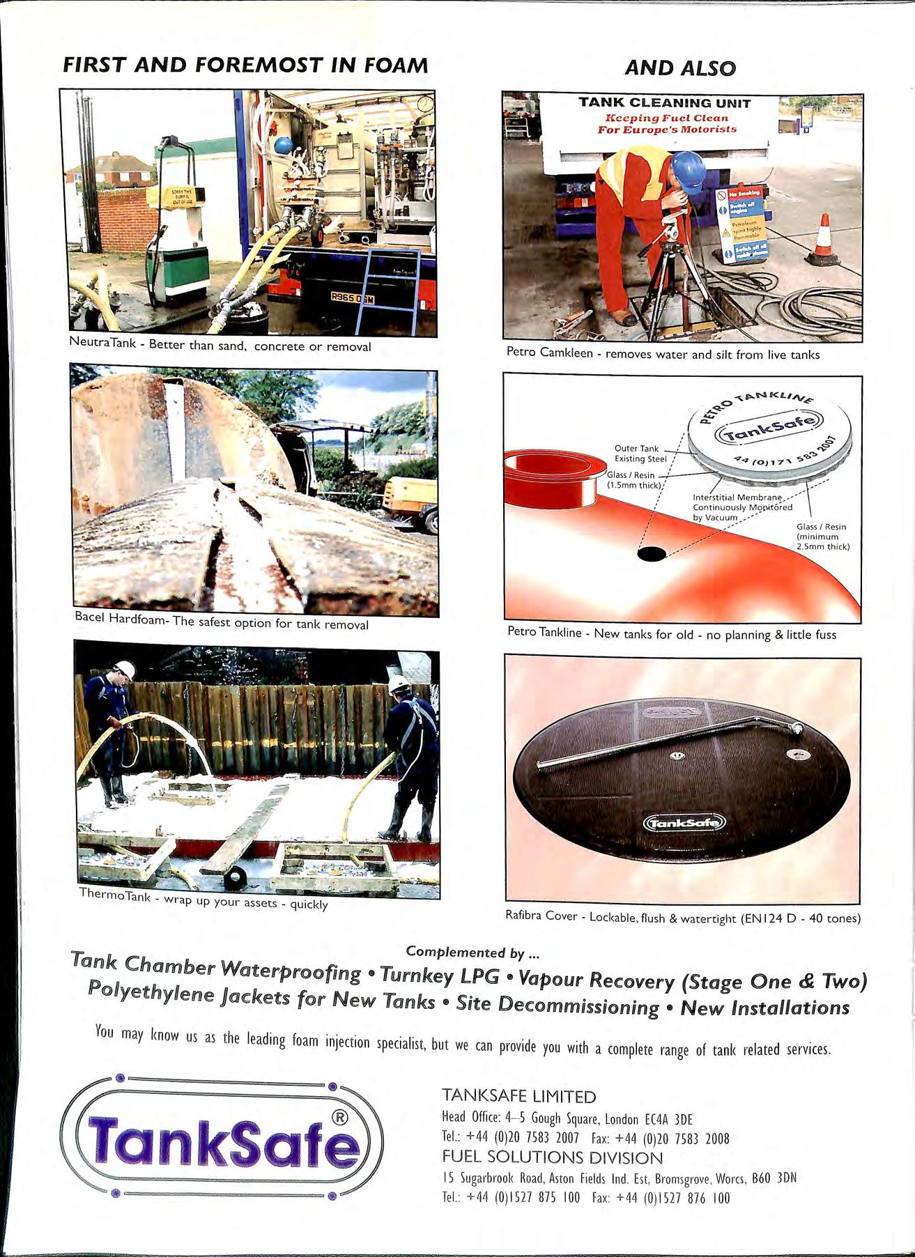
FIRST AND FOREMOST IN FOAM NeutraTank Better than sand, concrete or removal Bacel Hardfoam- The safest option for tank removal AND ALSO TANK CLEANING UNIT J\:c e ping Fuel C l ean For Europe 's Motori s ts Petro Camkleen removes water and silt from live tanks Petro Tankline New tanks for old no planning & little fuss Rafibra Cover Lockable, flush & watertight (EN 124 D - 40 tones) Complemented by Tank Chamber Waterproofing •Turnkey LPG •Vapour Recovery (Stage One & Two) Po Uyethy Uene }<ac::k ets for New Tanks • Site Decommissioning • New Installations You may know us as the leading foam injection specialist, but we can provide you with a complete range of tank related services. ======================== • TANKSAFE LIMITED Head Office: 4 S Gough Square, London EC4A 3DE Tel.: +44 (0)20 7583 2007 Fa x: +44 (0)20 758 3 2008 FUEL SOLUTIONS DIVISION 15 Sugarbrook Road , Aston Fields Ind. Est, Brom sgrove Wares , B60 3DN Tel. : +44 (0)1527 875 100 Fa x + 44 (0)1527 876 100

wRJ & NJ WlIJLJLJIAMS JLID w SOUTHERN LTDW Building & Civil Engineering Contractors Main Contractors to the Petroleum Industry for over Z 5 years & Build/Tendered/Negotiated Management Car & Jet Wash Installations Tank Removal & Disposal Fuel Tank Installations to Quality BS EN ISO 9002 : 1994 Are a of Op e ration Safety Procedures Client Driven RJ & NJ Willia ms Limited Te l: 01752 201 3 00 Fax: 01752 201299 Wil1 iams Southern Limited Te l: 016 3 5 8 71 8 2 8 Fax: 016 3 5 871784 SAFE, AUTOMATIC AIR-LOCK RELEASE Just one of the benefits of the new Just one item in our product Range Vapour Recovery, Valves & Fittings, Manholes & Covers, Pipework, Spill Containers, Tank Truck, Nozzles, Gauges. The EBW Group Worldwide, Partners in Technology PO Box 5499 , Wigston , Leice ster, LE18 2ZE , U K mail Tel + 44 (OJ 116 277 2700 Fax + 44 (O) 116 277 2900epaulchaw ner@e b w -apt.co.uk THE FASTEST WAY TO :Put 2",3" & 4" threaded entries into tank lids Remove drop tubes Install & supply OPD's (including 4" steel tubes) Remove any existing sockets Safe accepted by HSE & all appropr iat e safety authorities Quick • C ost effective IT MAKIES GOOD SE N SE TO USE ..... BORTEC Lid H udson Hill , H edin gham Road,Wet her·sfield , Brain cr-ee, Essex C M ? 4 EH Tel( Ol 37 1) 85 0 92 1 Fax (01 37 1) 85 0 7 19
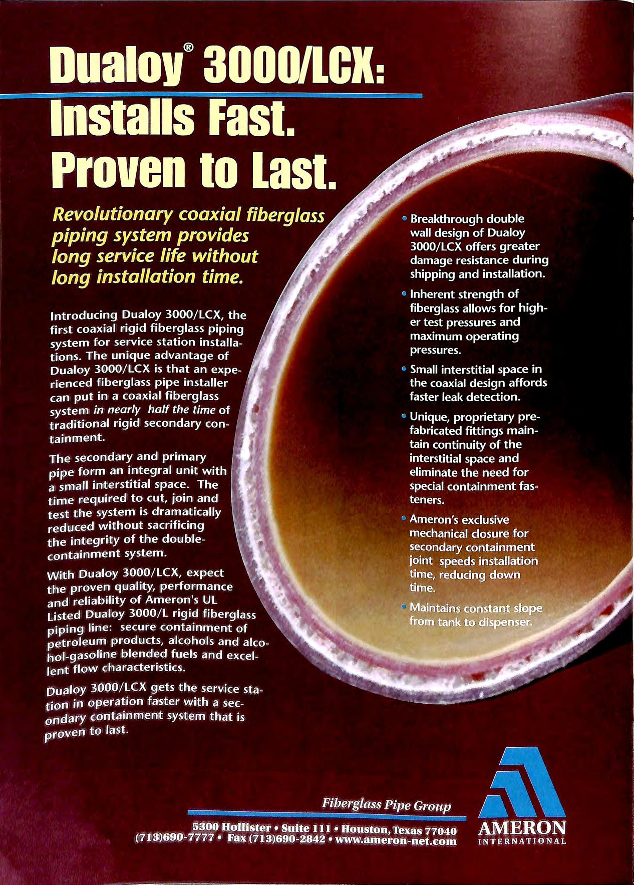
Environmental Engineering & Applied Science Extensive experience in undertaking specialist contaminated land remediation in the UK and Europe provides clients with tried and tested methods, applied by specialist staff, for dealing with polluted land and groundwater. • Site assessment on petroleum retail sites and industrial premises • Fully costed remedial design proposals • Execution of remedial works with minimum disruption • Confidential prompt and professional service SPECIALISTS IN CONTAMINATED LAND CONTRACTING Telluric Ltd, Meandros House , 54A Bute Street , Cardiff Bay , CF1 6AF. Tel: 01222 303010 Fax: 01222 303011 Toureen (Plant) Ltd. CIVIL ENGINEERING & DEMOLITION CONTRACTORS SPECIALISTS IN DEMOLITION AND DECOMMISSIONING OF PETROL STATIONS • • • • • Tank De-gassing and Removal Tank Installation Tank Cleaning Ga s Free Certification Forec o urt Breakout and R e in statem e nt 247 Ch a pter Ro ad , Will es den , Lo ndon N W 2 5LU Te l: 0181 451 200 2 Fax 01 8 1 4 59 2 14 6 M o bil e : 0 83 1 355 6 55 0777 5993 0 30 0374 269 73 6 •"""' · ., " ' CARD READERS DISPENSERS (ALL O PTIONS AVAILABLE) TANKS ELECTRONIC LOCKS ELECTRICAL INSTALLATIONS CIVIL ENGINEERING PIPE INSTALLATIO NS CONSULTANCY SERVICE TO COMPLETE LPG INSTALLATIONS TEL: 01905 729662 SPECIALIST IN ALL TYPES OF PETROLEUM INSTALLATION CONTRACTING & MAINTENANCE. INDUSTRIAL I COMMERCIAL I AIR CONDITIONING . WITH OVER 20 YE ARS EXPER IE NCE 24 HR. 7 DAY SERVICE ALL YEAR CALL-OUT FAC ILITY. •
TANK UNITS
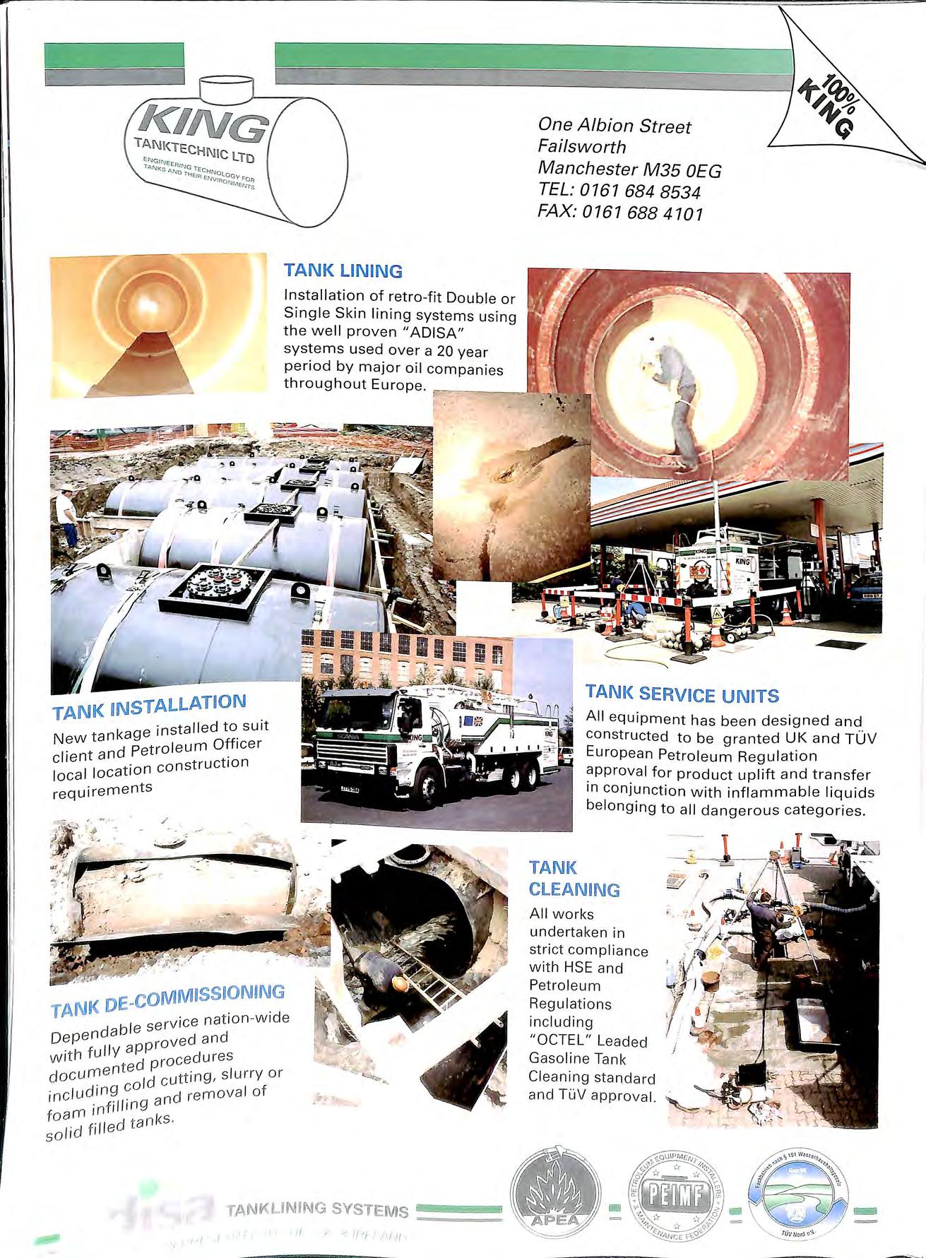
... ·: . ·nstalled to suit New Officer client and . e cons t ruction local location r e quirements /
LINING Installation of retro fit Double or Single Skin lin i ng systems using th e well proven "ADISA " systems used over a 20 year One Albion Street Failsworth Manchester M35 OEG TEL: 0761 684 8534 FAX: 0167 688 4107 period by major oil companies throughout Europe.
TANK
All equipment has been designed and constructed to be granted UK and TUV European Petroleum Regulation approval for product uplift and transfer in conjunction with inflammable liquids be longing to a ll dangerous categories
NK DIE-IV . TA ice n at i o n w ide bl e se r v D epe n da roved a n d All works undertak e n in strict compliance with HSE and Petrol eum Regulation s in c ludin g " OCTEL " Leaded Gasolin e Tan k Cleaning st a nda rd and Tl'1V app r ov a l. w it h fu il Y doc u mente i d cutt in g , s l urry or . c /ud i n9 co d r emova l of i n i nf ill ing a n f oam d tan l<S · so l id f iil e TANKUNING SYSTE M S ,, •/ t I ---.;;;;:;....._ ,
TANK

·C')·s National Inspection Council 101 Eleclrical Installation Contracting E•C G c s a rage onsultancy ervices Ltd MEMBER OF • BRITISH SA F E T Y COUNCI L J?.i-..' ESTOR IN PEOPLE APPRO VED CONT RACTO R UNIT 10 MERTHYR TYDFIL INDUSTRIAL PARK PENTREBACH MERTHYR TYDFIL MID GLAMORGAN CF48 4DR Telephone: (01443) 692008 Fax: (01443)692159 E.Mail : gcs.ltd@btinternet com Fuel tank, pipework & pump installations. Stage 1 B vapour recovery installations. Fuel monitoring & metering equipment. 26 Years of service to the petroleum industry Do you know that Pumptronics Europe manufacture Retail pumps for garage forecourts Commercial pumps for re-sale use Commercial pumps for in-house use LPG dispensers Lube oil dispensers Mechanical pumps W&M and non W&M units With or without air separation With hose retractors or high hose option Standard speed and high speed units Special ultra-high speed pumps Mono and twin vers ions in every range With new or refurbished hydraulics All housed in solid stainless steel cabinets ,,, Pumptronics Eu rope Limit ed ,,, Fa /g ale Roa d. N oith Wais/Jam Norfo lk NR 28 OA J UK Te/ · +44 (0) 169 2 500640 Fax +44 (0) 169 2 406 7 10 E -m ail : sales@ p um p tronics co uk


DO YOU HAVE Fuel Storage Tanks Separators and Interceptors CORROSION WORRIES? FIBRE REINFORCED PRODUCTS LIMITED DO YOU WANT TOTAL CORROSION RESISTANCE? ZERO TANK MAINTENANCE? CATHODIC PROTECTION NEED? HEAVY LIFT PROBLEMS? LIGHT WEIGHT/EASE OF INSTALLATION? DOUBLE WALL TANK INSTALLATION AT MAIDSTONE IF YOU NEED DOUBLE WALL TANKS WITH LEAK MONITORING WE NOW HAVE THE ANSWER IN G .R.P. • Full 360 ° interstitial space monitored by air pressure or liquid head • Meets EN976 , HS(G )4 1 and MOD/DMG14 specifications • Ea sy to install in granular material pea gravel OR crus l1 ed stone • No co rrosion , no cathodic protection and no protective coatings to damage • 30 year Warranty plus minimu m 50 year Design Life (EN9 76 requirement) • Competitively Priced For further details con tact:- FIBRE REINF ORC ED PRODUCTS LI MITED 2 WH ITEHOUS E WAY SOUT H WEST INDU STRIAL ESTATE PETERLEE CO DUR HAM SR8 2HZ • Comprehensive Eco Ception range • Eco-Ceptor Class I and C lass II Full Retention Interceptors • Ec o-Pass C lass I and C lass II By-pass Interceptors Independently tes ted to prEN858 and PPG 3 perfo rmance • Approved by LF CDA for Forecourt use TEL FAX : 019 1 5865311 0191 586 1274 E Mail frp@octacon co. uil Cc 11111 ca 10 N o F M1 1561
'] I I I I Durapipe - S&LP bb llllZ = =--EMCD WHEATON • environ A\n1ea11 on C>PW FUELING COMPONENTS EUROPE B V. .-=... A DOVER RESOURCES COMPANY AND MANY MORE The Worlds Major Forecourt Products from the UK's Major Distributor 0 . • D. Berry 81 Co (Pi pe Fitting Suppli es) Ltd., Un it 130, Midd lemore In dustr ial Estate, Ke nt ish Ro ad, B'h am 82 1 OAY. Te l: 01 21-55 8 4411 Fax: 0121 5546. t'. f>M ( N 'iTR A Tfr J!'
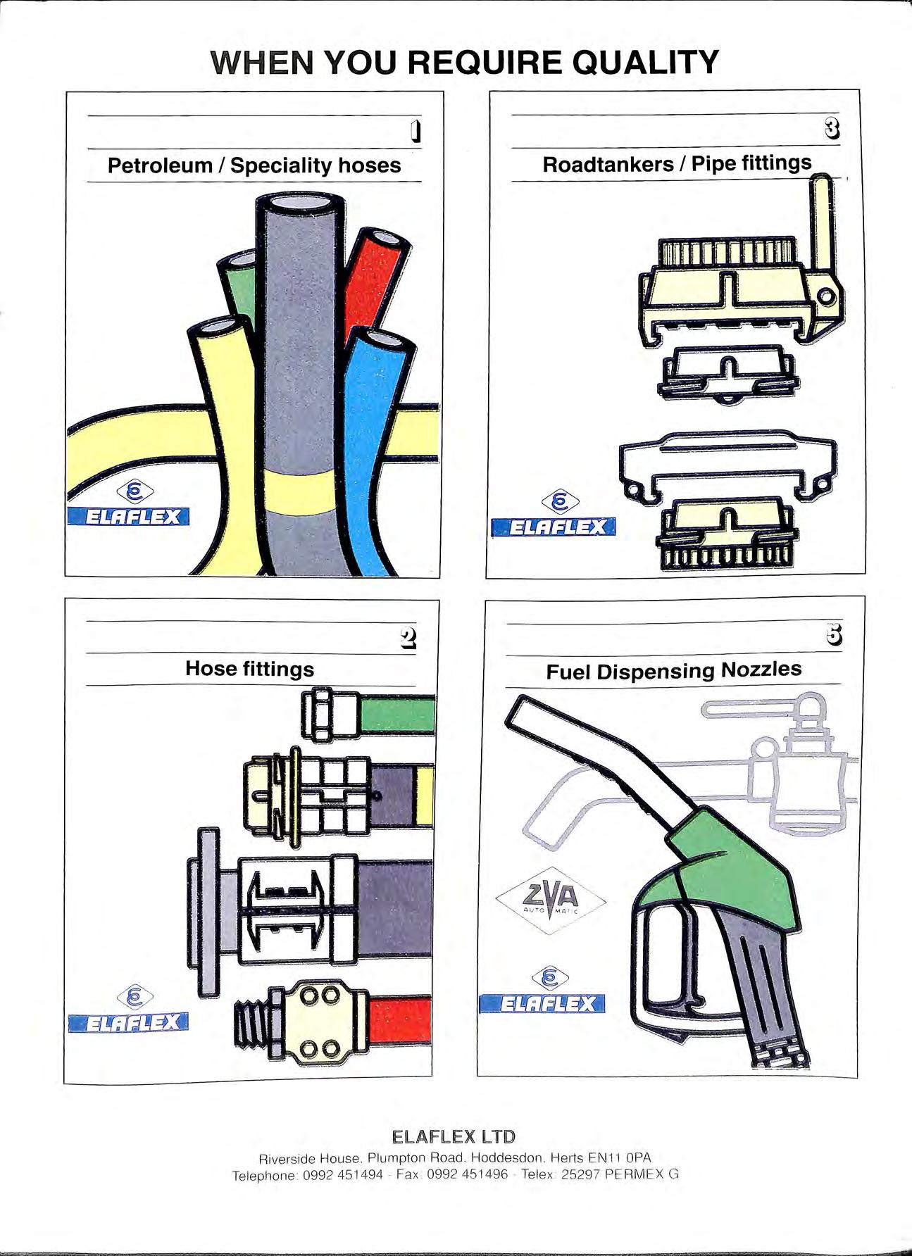
WHE N YOU REQUIRE QUALITY Petroleum I Speciality hoses Roadtankers I Pipe fittings Hose fittings ® ElAFLEX llD '·!ii ' Riverside Hou se. Plumpton Road Hoddesdon Herts EN 11 OPA Telephon e 099 2 45 1494 Fax 0992 4 51 496 Tel ex 2529 7 PE RM EX G
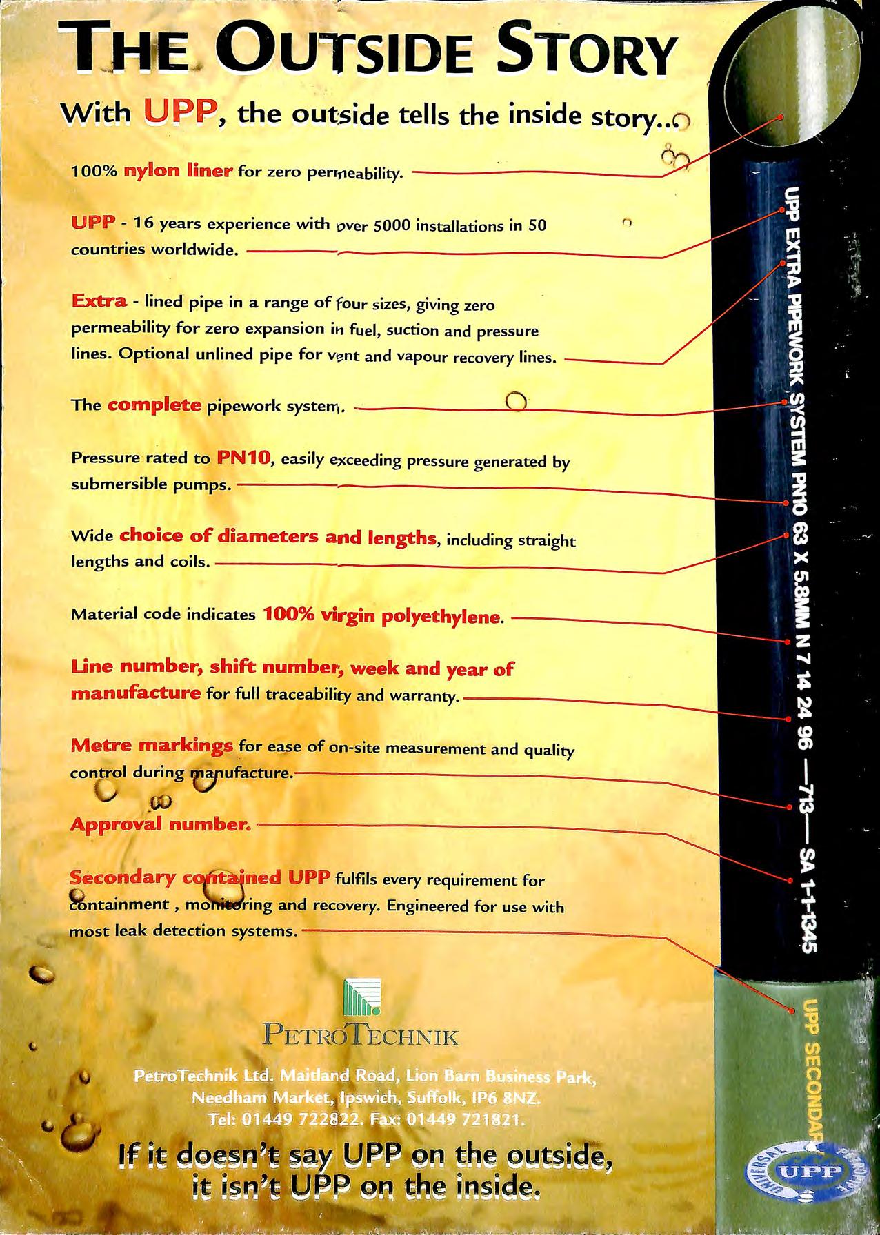
Mtith U BB , the out:side tells the inside story. .o ' Extra - lined pipe in a range of four sizes, giving zero p>ermeability for zero expansion i11 fuel, suction and pressure lines. Optional unlined pipe for vent and vapour recover:y lines. -----./ Pressure rated to PN10, easily e,c:ceeding pressure generated by submersible pumps. --------------::-----Wide choice of diameters and lengths , including straight lengths and ------------~--------: Une number, shift numbel", week and year of manufacture for full traceability and warranty. -------=----:---;=---Metre markings ea..se of on-site measurement and quality control during V1 ufacture.-------------------. Approvalnumbe~ --------------~----------------------Secondary UPP fulfils every r:equirement for , mo ing and recevery. Engineered for use wi t h most leak detection systems. ------------------PETROTECHNIK
