Tim Dimopoulos, Vice-President tdimopoulos@annexbusinessmedia.com
Scott Jamieson, COO sjamieson@annexbusinessmedia.com
Mike Fredericks, President & CEO
Machinery and Equipment MRO is published by Annex
Business Media, 111 Gordon Baker Rd., Suite 400, Toronto ON M2H 3R1; Tel. 416-442-5600, Fax 416-510-5140. Toll-free: 1-800-268-7742 in Canada, 1-800-387-0273 in the USA.
Printed in Canada
ISSN 0831-8603 (print); ISSN 1923-3698 (digital)
PUBLICATION MAIL AGREEMENT #40065710
CIRCULATION
E-mail: bolechnowicz@annexbusinessmedia.com
Tel: 416-510-5182 Fax: 416-510-6875 or 416-442-2191
Mail: 111 Gordon Baker Rd., Suite 400, Toronto ON M2H 3R1
Subscription rates.
Canada: 1 year $65, 2 years $103 United States: 1 year $143
Elsewhere: 1 year $164 Single copies $10 (Canada), $16.50 (U.S.), $21.50 (other). Add applicable taxes to all rates.
All prices in CAD funds
On occasion, our subscription list is made available to organizations whose products or services may be of interest to our readers. If you would prefer not to receive such information, please contact our circulation department in any of the four ways listed above.
In 2019, Canada’s manufacturing industry, particularly Ontario’s, saw some significant ups but also its fair share of downs.
The ups. Toyota Motor Manufacturing Canada (TMMC) reconfirmed its commitment to producing vehicles in Canada by announcing that it will manufacture the next-generation Lexus NX at its plant in Cambridge, Ont., beginning in 2022. This is in addition to TMMC’s production of the Toyota Rav4 and the Lexus RX. TMMC is the largest Toyota production plant in North America and the second largest in the world. Over the last few years, Toyota has invested heavily in its production operation in Ontario, with both Premier Doug Ford and Prime Minister Justin Trudeau visiting the plant in 2019, for separate announcements.
Bombardier is also expanding its manufacturing footprint in Ontario. It’s planning to build a new Global Manufacturing Centre, set to open in 2023, at Toronto Pearson International Airport. Additionally, Bombardier is making a contribution to the Downsview Aerospace Innovation and Research Consortium, with the goal of developing an aerospace hub for academic research and training.
Unfortunately, Ontario also saw a number of slowdowns last year. One of the most significant was the closing of General Motors’ (GM) production plant in Oshawa. After a long history of producing vehicles in that city, GM decided to close the plant in 2019. However, it’s not all doom and gloom for auto manufacturer. It’s keeping one part of that plant for the Stamped Products and Service Operations; another part will be used for the test track for electric and autonomous vehicles. And, GM still operates its CAMI production plant and has technical centres in Oshawa and Markham.
Companies in other industries are also seeing ups and downs. Dow Inc., a U.S. chemical producer, is expanding its petrochemical plant in Alberta; Saputo Inc., a dairy company, announced it will be closing its plant in Ontario this year, and one in New Brunswick by early next year; and toy company Mattel Inc. will be closing a Montreal-based factory next year.
Sales in the sector were down, too. StatsCan’s latest numbers (from November 2019) show Canadian sales decreased 0.6 per cent (to $57 billion). While that number may not seem too large, it was the third month in a row where sales fell. However, sales increased in transportation equipment (4.2 per cent) and fabricated metal (4.7 per cent). In all, sales in 11 of 21 industries were down, including primary metal, chemical, and food.
From a provincial perspective, eight provinces saw sales drop in the sector, including Quebec, New Brunswick, and Alberta. In addition, overall, unfilled orders and inventory levels increased by 0.1 per cent and 0.5 per cent, respectively.
But Ontario’s sales increased last November, albeit slightly, by 1.4 per cent.
In another study published recently, StatsCan looked at the impact declines in the manufacturing sector have on employment. For the most part, full-year, full-time employment rates for women were not affected by the decline in the manufacturing sector. By contrast, the decline in this sector had a large impact on employment rates for men. Between 2000 and 2015, the employment rate for men between ages 21 and 55, who worked full-time for at least 48 weeks, was down to 58.6 per cent (a drop of five per cent).
While manufacturing may never return to its heyday, there continues to be a large manufacturing sector in this country. Though some companies may be closing plants, others still continue to invest in their Canadian manufacturing operations. A host of smaller manufacturers are growing at steady rates, filling the hiring gap with expanding workforces. This year offers new opportunities for manufacturers despite a few down sectors, so things are looking up.
Machinery
Mario Cywinski Editor
SKF Pulse™ Machine monitoring made easy.
Gain operational insight like never before with SKF Pulse.
The SKF Pulse portable, Bluetooth™ sensor and free mobile app help you predict machinery issues before operations are impacted. Monitor vibration and temperature data on your rotating equipment, without the need for training or diagnostic expertise.
Tap into decades of SKF predictive maintenance and rotating machinery analysis expertise through SKF
Rotating Equipment Performance Centers, dedicated to improving your operation and finding solutions for every performance challenge.
SKF is your partner in moving toward a digital future. Visit skf.ca/skfpulse to see how SKF Pulse can improve your operation.
Contact your SKF authorized distributor for a quote today. You will be surprised how cost effective SKF Pulse is.
CMMS Q & A
The benefits of using CMMS software.
Main Electrical Substation Upgrades / 8
Design considerations, planning, and equipment selection.
MRO Quiz / 16
How contaminated lubricants are a machine killer.
Lexus Invests in Canadian Operations / 22 Lexus Canada to build Lexus NX vehicles in Ontario.
Maintenance 4.0 vs CMMS
Examining the effects of the Maintenance 4.0 revolution on the current CMMS system.
What’s Up Doug / 14
How do we preserve assembled bearings?
Maintenance 101 / 18
Types of condition-based monitoring.
Condition-based Maintenance / 24 It will not stop your machines from failing.
Departments
Editor’s Notebook / 3
Industry Newswatch / 6
Mr. O / 30
Spare Parts / 30
Events
SKF Hosts STLE Toronto
Workshop / 7
Product News
What’s New in Products / 28
Twitter: @mro_maintenance
Instagram: @mromagazine
LinkedIn: linkedin.com/company/ mro-magazine
Cover
VM / Getty Images
Bombardier to Build Global Manufacturing Centre in Mississauga
BY MARIO CYWINSKI
Bombardier has signed a long-term lease agreement with the Greater Toronto Airports Authority (GTAA) to build a new one-million square-foot global manufacturing centre at Toronto Pearson International Airport in Mississauga, Ont.
Site work has begun at the centre, which is slated to open in 2023. The centre will be the final assembly operation for all Global business jets for the company. It will replace the current site at Downsview in Toronto.
“Today, I’m very excited to announce the relocation of our global aircraft family production activities to a new,
CTMA Elects New President
BY MARIO CYWINSKI
The Canadian Tooling & Machining Association (CTMA) named Chris Hergott as its new President.
Hergott has 27 years of tooling industry experience. He began his career at Millard Precision Machine and Tool, and also spent time at BES Tool and Die, as well as Diemedic Tool and Machine.
In 2001, he partnered with Gord Jokic of XL Tool Inc. and helped grow the company, which is now operating out of a 36,000 sq/ft facility in Kitchener, Ont. In 2009, they started a tool shop in Queretaro, Mexico.
Hergott has expertise and experience in and knowledge of the industry, and several years serving on the Board of Directors of the CTMA. MRO
cutting-edge manufacturing facility at Toronto Pearson. This is a strategic move for Bombardier and a strong commitment to Ontario’s aerospace industry. It will allow us to offer worldclass career opportunities and continue fuelling the economic development of the region for years to come,” said Alain Bellemare, President and CEO, Bombardier Inc.
Bombardier is also giving a multimillion-dollar contribution to the Downsview Aerospace Innovation and Research Consortium to develop an aerospace hub for academic research and training activities. MRO
TMMC’s New President
BY MARIO CYWINSKI
Toyota Motor North America (TMNA) has appointed Frank Voss as President of Toyota Motor Manufacturing Canada (TMMC). Voss took over for Fred Volf, who retired on January 1, after 32 years with Toyota.
Voss has over 30 years of automotive manufacturing experience, and has previously held several management positions at TMMC, including General Manager of the Lexus Manufacturing Division, GM of Production Control, and GM of Information Systems. He was most recently Vice-President, Administration, and Corporate Secretary at Toyota Motor Manufacturing Kentucky, Inc. (TMMK).
Voss will now be responsible for all production and administrative functions at TMMC. He will report to Brian Krinock, Senior Vice-President, Vehicle Manufacturing, TMNA.
Volf has been with Toyota since 1987, starting at TMMC. Before becoming President in 2015, he was Vice-President, Manufacturing for Toyota Motor Manufacturing Mississippi Inc. (TMMMS), and was also Vice-President, Manufacturing, at TMMC. MRO
Erbessd Instruments Expands to Canada
BY MARIO CYWINSKI
Erbessd Instruments, a vibration analysis, balancing, alignment and online monitoring company, is expanding to Canada through a strategic distribution partnership.
“Canada and Europe represent strategic growth markets for our team," said Dr. Michael D. Howard, CEO, Erbessd Instruments. “We have long served these markets from our North American offices; however, our customers deserve the very best support and service possible. We are quite confident that the years of experience these new team members bring to the table will further propel the company and assist the company in achieving our strategic goals.”
Erbessd Instruments family of companies is welcoming Phoenix Monitoring Technologies Inc. and Ken Vander Eyken to Erbessd Instruments Canada of Niagara Falls. Vander Eyken is a veteran telecommunications executive and business leader, and will serve as the Managing Director for Erbessd Instruments Canada and provide full lifecycle support for Erbessd solutions. MRO
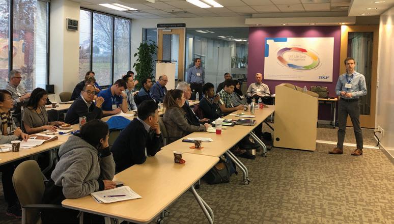
STLE Toronto Workshop
BY MARIO CYWINSKI
The Society of Tribologists and Lubrication Engineers (STLE) Toronto Section, recently held a workshop that looked at reducing tribological losses and failures. The workshop took place at SKF Canada's offices in Toronto. Invited speakers covered a broad base of topics encompassing the lubrication industry.
Colin Lewis from SKF presented Cost Savings Through Total Cost of Ownership, which looked at how a lower initial price may not save money in the long run, but how looking at the total cost of ownership could be the way to do so. He provided several examples of how this is put into practice. Lewis described looking at only the initial price as the “priceberg,” with the price being the visible part and total cost of ownership being what is under the water. Cory MacLeod from Lanxess Solutions US, Inc. spoke about formulating with synthetic base oils for improved lubricant performance. He outlined how, as a result of higher performance requirements from lubricants, synthetic base oils are becoming more popular in meeting these. MacLeod outlined some advantages of synthetics, such as increased service life, reduced energy consumption, and longer machinery life.
Bernie Hall from Checkfluid outlined How Better Oil Sampling Practices Drive Bottom Line Profitability. Hall discussed the ways to sample oil; sampling valves, vacuum pump, and tubing, and sampling from the drain; and the pros and cons of each. He also mentioned that good data is the most important aspect of an oil
analysis program. Omron Industrial Automation’s Chris Barnes discussed predictive maintenance solutions. Barnes looked at current analysis, vibration analysis, insulation resistance monitor, and thermography, and used case studies to show how PdM is important by way of motor and sensor case studies.
Sean Miller from UE Systems Inc. offered information on ultrasound assisted lubrication. He spoke about how the technology can help in reducing over- and under-lubrication, as well as how it is moving lubrication maintenance to condition-based and away from time-based. Miller also provided audio examples (by using ultrasound) of under- and over-lubricated bearings.
Bookending the workshop was another SKF speaker, Devan Devalia, who discussed Bearing Damage/Failure Analysis. Devalia discussed the most common bearing arrangement problems, outer ring rotation, inner ring rotation, excessive axial load, misalignment, and oval compression. He also spoke about type of failure modes; wear, fatigue, corrosion, brinelling, erosion, deformation, indentation, and cracking and fracture. MRO
Main ELECTRICAL SUBSTATION Upgrades
Design Considerations, Planning, and Equipment Selection
BY PHILIP CHOW AND BAVAN POOLOGARAJAH
Institutional campuses and large facilities share a common design feature: the use of a main outdoor electrical substation, used to distribute power to buildings and site loads across a large area. With an electrical demand load (kW or kVA), typically proportional to the size of the facility, campuses are often supplied by one or more electrical utility circuits at a supply voltage of 15kV or higher, due to circuit loading and ampacity constraints.
Incoming utility circuits are routed to a main outdoor electrical substation, which serves as the demarcation point between utility infrastructure and customer-owned electrical infrastructure. From here, the incoming utility service is distributed within the campus either at the service voltage or at a lower voltage, through the use of step-down transformers. A main electrical substation is a major component in an infrastructure portfolio and facility managers often face the
problem of how to upgrade end-of-life equipment, without impacting operations.
Sunnybrook Health Sciences Centre (Sunnybrook) faced these challenges when it undertook a project to upgrade its main outdoor electrical substation. In this, the first of a twopart series on electrical substation upgrades, we will look at design, planning, equipment co-ordination, and procurement associated with this project.
Sunnybrook is a full-service, 1,355-patient bed hospital, with an aggregate campus area of approximately three million square feet. It is the largest regional trauma centre in Canada and has 1.3 million patient visits each year. At the onset of the project, Sunnybrook received its electrical service via two incoming 27,600V utility circuits. The existing outdoor substation consisted of 27.6kV load-break, switch and fuse type, switchgear, and four oil-filled power transformers, rated at 5/6.66 MVA ONAN/ONAF, which supplied a 5kV distribution network and approximately 20 smaller, downstream building substations.
Equipment in the existing substation had been installed over time, as campus development occurred, with the oldest sections of the existing switchgear lineup and power transformers dating to the 1970s. Routine preventative maintenance identified a number of issues with older equipment, including high dissolved gas levels in two of the power transformers (condition three and condition four dissolved gas levels), signs of corona damage on a high voltage bushing, and corrosion in the existing switchgear.
With equipment reaching end-of-life conditions and the future reliable operation of equipment being questioned, Sunnybrook undertook a project to upgrade its substation.
Photo Credit: Philip Chow
“Sunnybrook’s main outdoor electrical substation plays an essential role in distributing power throughout the campus,” said Michael McRitchie, Director of Plant Operations, Maintenance and Biomedical Engineering, Sunnybrook. “To ensure our substation would meet future campus needs, a project that completely upgraded the existing installation was prioritized.”
Given the large capital expenditure associated with building a new substation, an analysis of project goals and constraints was performed.
Project Design Goals Included:
• Increasing capacity within the new substation for future campus development;
• Allowing for the connection of a future combined heat and power plant and a future battery energy storage project;
• Developing a smart substation that would allow for improved monitoring and control features; and
• Improving on an existing automatic transfer system, which allows hospital staff to transfer between incoming utility feeders.
Project constraints included building within the footprint of the existing substation; creating a project schedule that aligns with funding requirements; minimizing any parking space losses in adjacent parking lots; and minimizing the impact of construction-related power interruptions to the hospital.
Project work would have to be carefully co-ordinated with work by Toronto Hydro, which included transitioning Sunnybrook from an overhead utility circuit to an underground utility circuit, replacing several kilometres of underground duct banks and utility cables for future capacity; and, to help fa cilitate construction of the new substation, replacing existing overhead switches with pad-mounted switchgear and upgrad ing utility metering and SCADA connections.
Design of Sunnybrook’s Main Outdoor Electrical Substation Redevelopment project commenced with the development of several concepts for a replacement substation. The first ma jor design challenge was selecting the new service entrance switchgear. With a requirement for future generation sources to be connected in parallel with the utility, associated utility grade protection, metering and control features, and the abili ty to automatically add and disconnect loads, it was clear sim ple switch and fuse type switchgear would not be sufficient for future needs. Vacuum circuit breakers and switchgear with customizable metering, protection, and control elements would be required.
Using traditional, air-insulated switchgear in a weatherproof enclosure was initially considered; however, the footprint of the proposed lineup would necessitate a substantial expansion of the substation area and the loss of adjacent parking spaces. Consequently, the use of sulphur hexafluoride (SF6) insulated switchgear, also known as gas-insulated switchgear (or GIS), was considered. Given the high dielectric strength of SF6, GIS provides a more compact installation, with a footprint that is approximately 50 per cent of the size of equivalent air-insulated switchgear.
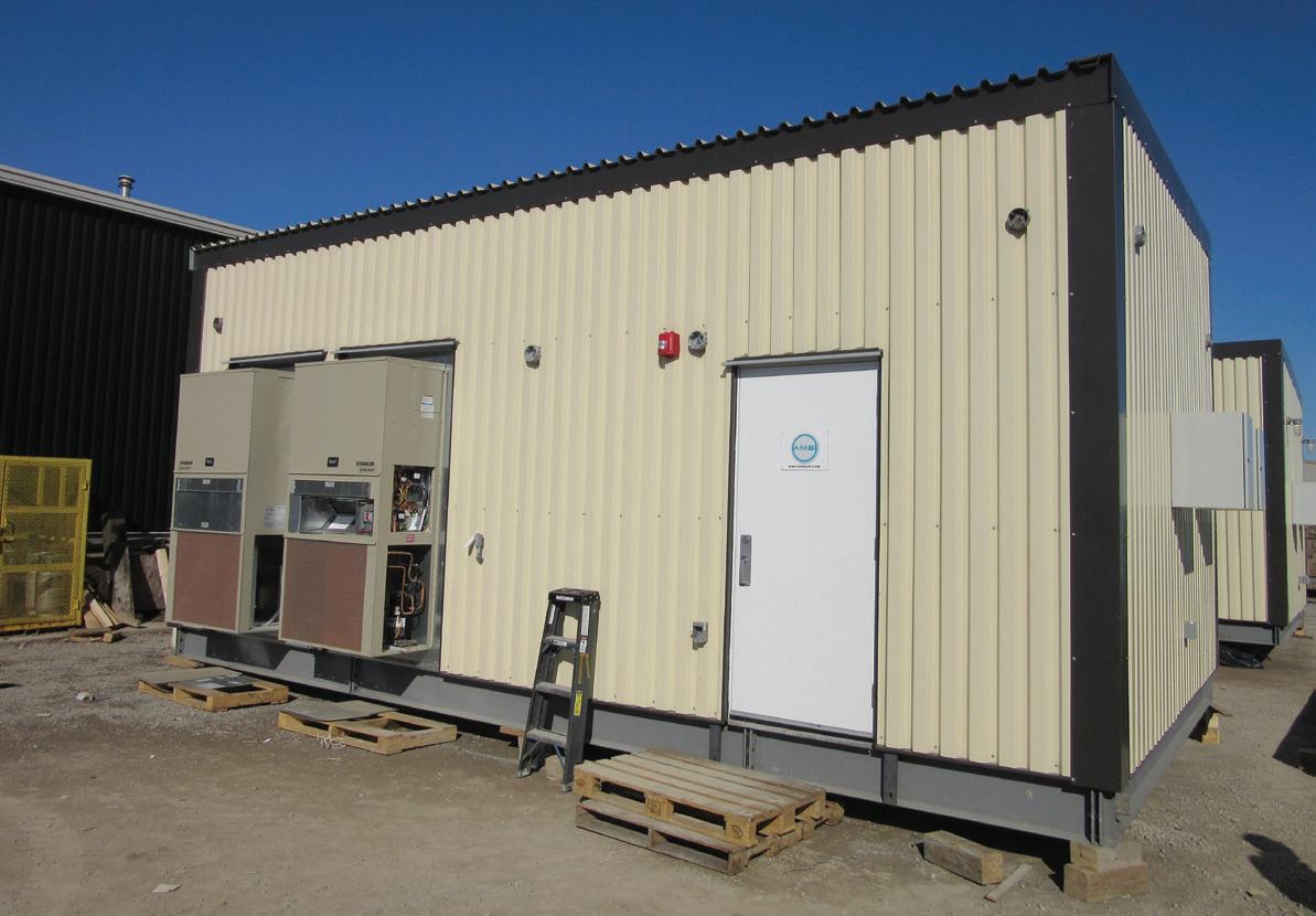
enclosures for the electrical equipment (E-Houses), with a conditioned environment, would need to be supplied along with the GIS.
The next design challenges included creating additional capacity in the electrical substation for future campus development and designing a control system that would provide automated control of the gas-insulated switchgear. A load study for the site was performed, and forecasted load growth was contrasted with site constraints, which included both physical spaces to build on and electrical constraints in the existing electrical distribution system. It was determined that the
While gas-insulated switchgear is available in varying configurations, traditional freestanding type switchgear was selected as the right option for the project, given its ability for customization and improved ease of operability. Using panel type gas-insulated switchgear would require an indoor environment. As the funding constraints for the project prohibited the construction of new occupiable space, prefabricated
existing 5MVA transformers could be replaced with four new 7.5/10 MVA KNAN/KNAF transformers, increasing the aggregate capacity of the new substation by a factor of 1.5 on the base rating (30MVA).
Completely replacing the existing transformers would also provide an opportunity to incorporate several innovative design features, including on-board dissolved gas analysis monitoring, alarm integration with the substation’s TCP/IP based control system, and improved transformer protection features with new protective relays. To improve power system reliability, an automatic transfer system was included to provide the ability to automatically switch between the two incoming utility circuits, in the event of an outage on a utility circuit.
Additional features included load management of 27.6kV feeder; user-friendly HMI screens with metering, alarm, and control features; and full hot/standby capability with redundant PLCs and system components. To integrate with the existing alarm and control system for the campus emergen-
cy generators, an Allen Bradley ControlLogix platform was used.
With major equipment concepts finalized, detailed engineered drawings and specifications were created for equipment procurement packages. Given the integrated requirements between the gas-insulated switchgear, its associated control system, and the E-House enclosures, one consolidated equipment procurement package was developed for GIS suppliers. A second independent procurement package was developed for the four 7.5/10 MVA liquid-filled power transformers.
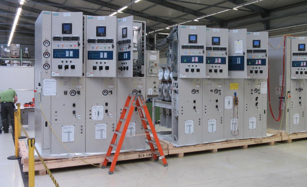
Equipment suppliers submitted proposals for the separate packages and submissions were evaluated through a detailed RFP process, which reviewed bid compliance, company capabilities, production schedule, price, and other factors. The gas-insulated switchgear package was awarded to Siemens Canada, with Toromont CAT as the control system sub-supplier and AMSi Inc. as the E-House sub-supplier. The power transformer package was awarded to Northern Transformer Corp. Suppliers were directed to proceed with detailed design for equipment shop drawings, while the engineered design for the construction package was finalized.
“Pre-selecting major equipment provides an excellent opportunity for the owner to have direct input into the procurement process and to advance the project schedule,” said McRitchie. “Developing equipment procurement packages, selecting suppliers, and having detailed equipment shop drawings produced, prior to construction, allowed the construction team to focus on delivery and installation.”
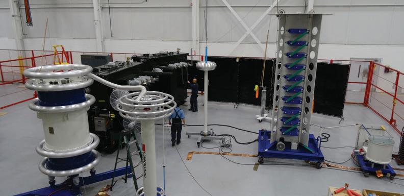
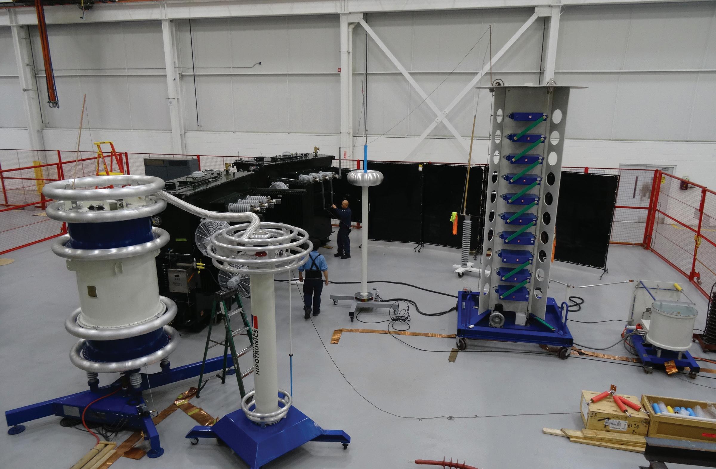
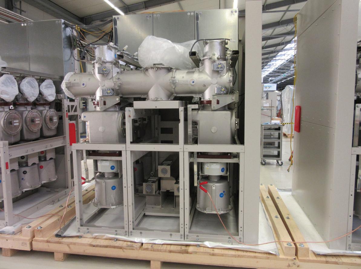
As the pre-selected equipment would be critical to the successful operation of Sunnybrook’s new substation, a rigorous quality assurance program was maintained throughout manufacturing. The 38kV class gas-insulated switchgear underwent in-depth acceptance testing at the Siemens factory in Germany, with both the project engineer and hospital representatives attending.
Tests included a detailed inspection of components, mechanical and electrical operation tests, dielectric tests, verification of interlocks, and SF6 gas measurement tests. Once initial factory witness tests were successfully completed, the GIS was cleared for shipment to Canada. Several months later, the switchgear sections were installed in two separate E-House assemblies, complete with automatic transfer system (ATS) control cabinets. The E-House assemblies were equipped with a multitude of custom features, specified by the project engineers, including redundant HVAC systems, redundant DC
Photo Credit: Philip Chow
power systems for station power, clean agent fire suppression systems, and specific criteria for construction of the enclosures and finishes.
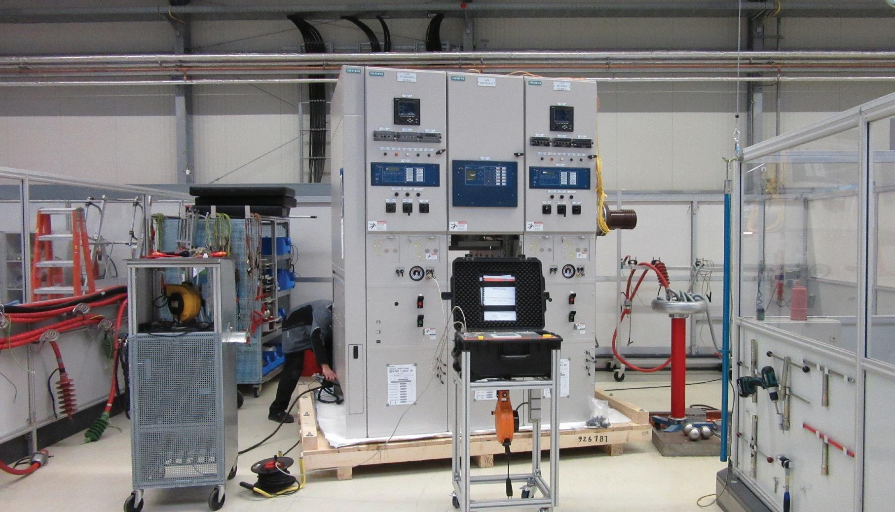
An integrated acceptance test was subsequently performed, which tested the functional operation of the switchgear’s ATS, through the custom control system and HMIs, and tests of the various systems in the E-Houses and protective relays in the switchgear. Concurrently, the new power transformers were prepared for in-depth acceptance testing at the high voltage test lab at Northern Transformer’s factory. Transformer acceptance testing included a detailed physical inspection, heat run tests, electrical tests, dissolved gas analysis monitor tests, and lighting impulse (BIL) tests. Once the new substation equipment successfully passed all of the required off-site testing, it was cleared for shipment to the site.
Upgrading critical electrical infrastructure in a campus’ main outdoor electrical substation can require significant upfront planning. Decisions on equipment technologies, capacities for future load growth, and opportunities for functional improvements, both for operation and maintenance, need to be made before proceeding with the detailed design for construction drawings and specifications.
Given the complexity associated with procuring integrated equipment packages, and the desire to have technical and functional merits included in the bid evaluation process, it can be advantageous to have the owner and their engineer manage equipment procurement.
In the second part of the series on substation upgrades, we'll examine the multi-phased construction project that allowed Sunnybrook to completely upgrade its main outdoor electrical substation, while minimizing power interruptions to the campus.
MRO
Philip Chow, P.Eng., P.E., was the lead engineer on the project and is a senior project manager at H.H. Angus & Associates Ltd. He specializes in electrical projects and construction in critical facilities and can be reached at philip.chow@ hhangus.com.
Bavan Poologarajah, EIT, was the senior electrical designer on the project. He has worked on a number of electrical projects in critical facilities and can be reached at bavan. poologarajah@hhangus.com.
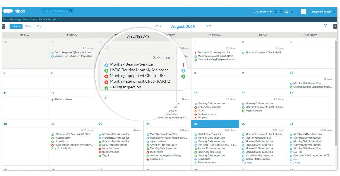
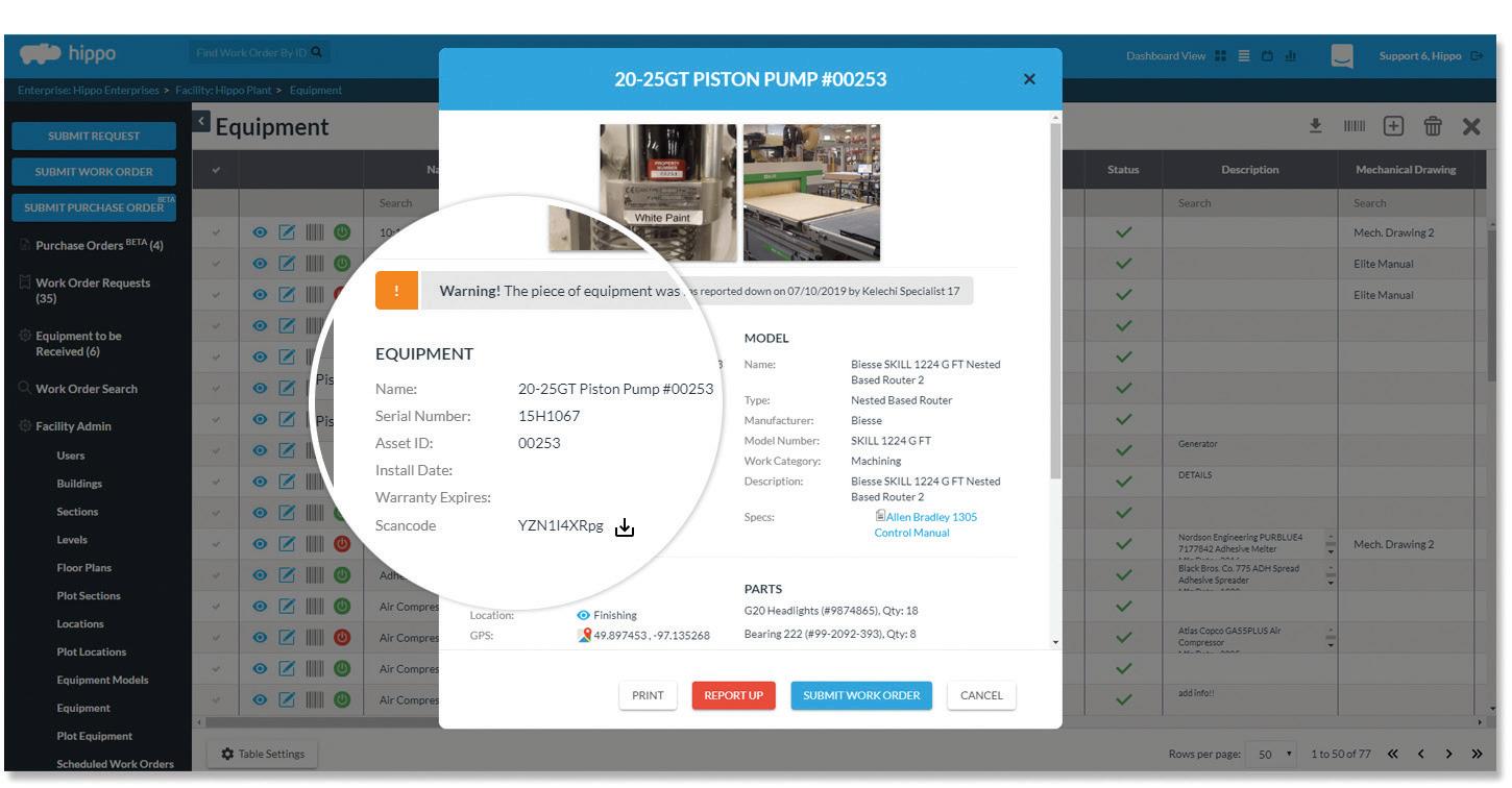
BENEFITS OF USING CMMS SOFTWARE
BY MARIO CYWINSKI
Hippo CMMS has been involved in maintenance management for over 20 years. It began when a Winnipeg-based architectural firm developed a preventive maintenance platform for its clients. It was native SaaS, affordable, and easy to use, which, at the time, helped to distinguish it in the market. In 2004, a complete rebuild and rebranding took place, and Hippo CMMS was launched.
MRO recently spoke with Daniel Golub, Chief Operating Officer, Hippo CMMS, to get his take on the benefits of using a computerized maintenance management system (CMMS), why some companies aren’t using one, and where
he sees the technology going in the future.
MRO: What are the main advantages of using a CMMS?
GOLUB: A good CMMS puts everything in one place, then keeps it both safe and accessible.
Many advantages come from the software’s ability to streamline processes. Work order management, for example; tickets come in through the request portal and are sent directly to the maintenance manager. Once they're approved, the manager can generate, prioritize, delegate, assign, and track data-packed work orders. Everything is done in the
software, where it's kept up to date in real time and accessible from any internet-connected device. Other advantages come from how departments can leverage data they collect about their operations. With auto-generated reporting and KPI tracking, they can see the maintenance big picture, and that means data-driven decision-making. No guessing on repair-or-replace, no wondering which resources are most productive.
MRO: No longer a product for larger corporations, a CMMS is now for any company. What would you say are the main advantage of a CMMS for small to medium-sized companies?
GOLUB: The biggest advantage is getting the functionality of older on-premises systems without the upfront and ongoing costs. With modern cloud computing-backed platforms, your CMMS provider takes the IT weight off your shoulders. It looks after hosting and data backups, software updates, and security.
Further, there is now an app for almost every business function, and, in order for companies, large and small, to remain competitive, they need to be efficient. What was once out of reach for small businesses is now right there for them in the mobile device in the palm of their hand.
MRO: What are some of the main reasons companies are not using a CMMS?
GOLUB: We hear many different reasons, none of which are good. Since maintenance departments are traditionally seen as cost centres, some companies are hesitant to invest in a CMMS. However, the reality is, a good CMMS cuts downtime and boosts productivity. A CMMS work order has everything a maintenance professional needs to close out efficiently, including step-by-step instructions, lists of associated parts and materials, and digital versions of O&M manuals and interactive floor plans. When maintenance professionals don't have to waste time filling out paperwork, scrolling through e-mails looking for spreadsheet attachments, or running to the office to pick up their next assignment, departments get more bang for their maintenance buck.
MRO: What advancements do you see in CMMS in the next few years?
GOLUB: It's an exciting time, and there's a lot of talk about how operations will find new ways to collect and leverage
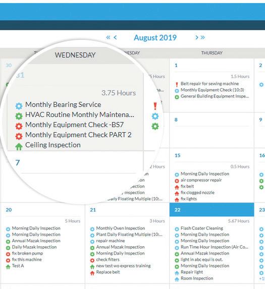
Photo Credit: Hippo CMMS
their data. The use of sensors is going to rise as prices fall, and that’s going to increase the use of condition-based and predictive maintenance.
We predict that integration will also grow in importance. Companies will look for new ways to get their software platforms talking and sharing information. APIs are going to be a big part of that push.
MRO: Outline the products Hippo provides to its CMMS customers.
GOLUB: Hippo CMMS is a simple solution that equips companies with tools to manage work orders, preventive maintenance, equipment and inventory, and purchase orders. CMMS Hippo also tracks downtime and generates reports on maintenance activities.
MRO: How do Hippo’s products differ from others on the market?
GOLUB: For users, the learning curve is fast, implementations are smooth, and adoption rates are high. This translates into seeing an ROI early on when the momentum is there. Hippo is not the most robust CMMS on the market, and we are not trying to be. We have focused our energy and resources on the user experience, and ensuring Hippo is a solution that is easy to implement and our customers get value from it early on. Hippo’s UI is designed so that it's intuitive and not cluttered with every feature possible. Our users appreciate this, and that is the main reason for our success.
Throughout Hippo’s history, one thing that's never changed is our focus on making easyto-use software, and our hard work has paid off, We've grown to 1,300 customers and have a 92 per cent retention rate. In July 2019, we were acquired by iOFFICE, and are now a part of their asset division. MRO
Mario Cywinski is the Editor of Machinery and Equipment MRO magazine, a member of the Automobile Journalists Association of Canada, and a judge for Canadian Truck King Challenge. He has over 10 years of editorial experience and over 15 years of automobile industry experience, as well as small business industry experience.
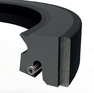
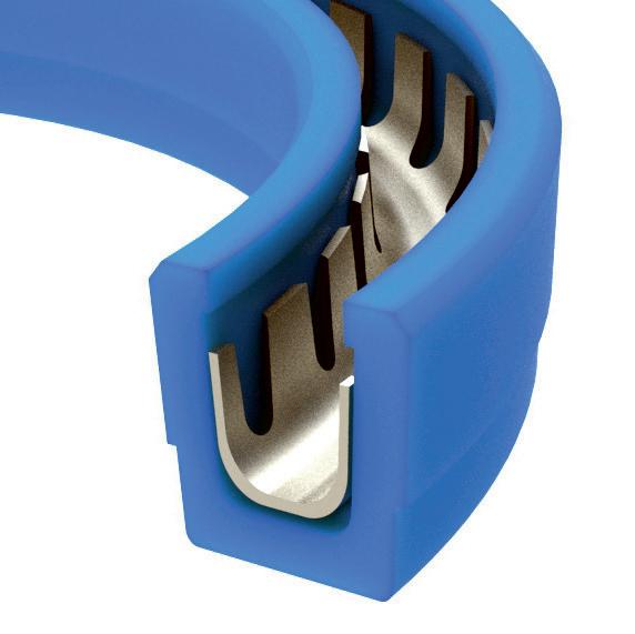
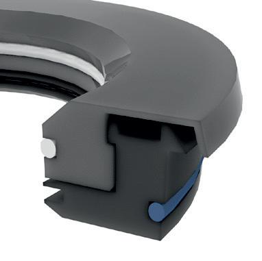
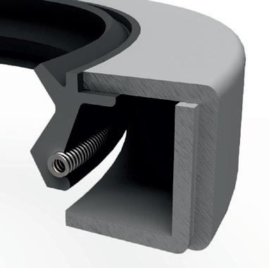
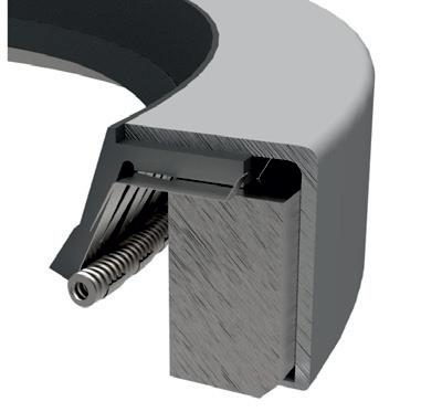
THE SPLIT MAKES
THE DIFFERENCE
Announcement
Global Bear Inc. is pleased to announce the opening of a branch in Langley, BC.
The 3000sq. ft. facility will be stocked with a broad range of all the products distributed by Global.
“The plan has always been to have coverage across Canada”. “That dream has now become a reality”, stated Harold Benz, founder and President of Global.
We look forward to servicing our Western Canadian customers from the new facility and welcome all inquiries for bearings, belts and power transmission products.
Our stock, featuring CRAFT and NKE bearings in Langley, will help distributors service the “end-user” markets in Alberta and British Columbia.
call
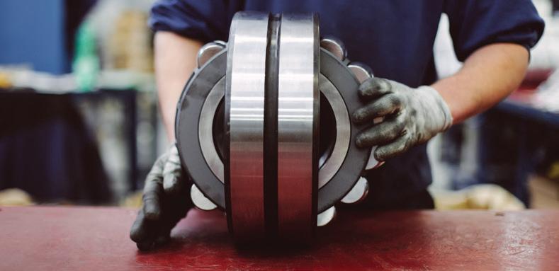
PRESERVING ASSEMBLED BEARINGS
BY DOUGLAS MARTIN
Recently, I was asked was what to do with bearings after they have been installed into a machine. In context, users will rebuild an asset, such as a pump or a motor, and then store it until needed. The time of storage of such assets could be two or three years.
The Question Is, Do We Preserve the Assembled Bearings?
The question refers mostly to open bearings in applications that are oil lubricated. Most often, these are process pumps that have an oil bath and are stored without oil; however, the discussion can apply to any oil-lubricated bearings put into storage “dry.”
Note: Damage due to vibration or shock loading during storage will not be addressed, as this is another topic. However, it is a critical factor when storing rebuilt assets.
There is very little documentation to provide a reasonable answer to assembled, long-term bearing storage from a bearing manufacturer. As soon as the bearing is removed from the box, it is considered the responsibility of the user. As soon as it is assembled into the asset, the bearing is expected to be lubricated and run. Unfortunately, this is not the case in real life, and it is up to the user to take action to protect the assembled bearing.
Some Basic Principles:
• Prevent moisture corrosion to the bearing;
• Ensure the coating or preservative you put on the bearing is compatible with lubricant that will be used to lubricate the bearings;
• Ensure the preservative will not harden over time, as this will affect the startup of the machine.
Over the years, the preservatives put on bearings have evolved. Years ago, a bearing was coated with a thixotropic fluid, which is thick or viscous under static conditions, then will flow over time when shaken, agitated, shear stressed, or otherwise stressed. Once coated, the bearings (typically larger ones) are wrapped tightly with an oil paper (VCI paper) then again with a polymer tape.
Although designed to be displaced by “working” (i.e., when
the bearing starts to rotate), the material—due to storage for an extended period or exposure to the environment—can harden and may need to be washed off.
More recently, the preservative used by bearing manufacturers is a vapour phase inhibitor, which is very thin and is constantly evaporating and re-condensing on the metal surfaces such that the surfaces are constantly being re-coated. The downside to such a preservative is that if the bag in which that bearing is sealed is broken and exposed to the atmosphere, the preservative will evaporate into the atmosphere and deplete itself. As such, bearing manufacturers will not accept returns in which the plastic wrap of a bearing has been opened.
There are products out there that are made for protecting metal surfaces during storage. Mobil has a whole line of products. SKF uses Zerust/Excor for its packaging. SKF Canada uses Houton Rust-Veto 342 to preserve housings made locally. These are only examples of products, it's best that you contact your lubricant/metalworking fluids supply company to see if it has a product that would suit.
Recently, I had an experience with a customer who was greasing their bearings with a standard lithium/mineral oil grease. Although there was no documentation of the process and product used, and there was no startup or premature failure issues, there was; however, an incident in which, the oil in the sight glass of a newly installed pump was a milky colour.. At first, it was thought there was water emulsified in the oil. However, upon inspection of the "assembly" grease ad hoc procedure, the error was discovered.
What is the right choice? A thixotropic fluid coats well, but there is a long-term risk of hardening as the solvent evaporates. A vapour phase inhibitor does not require any flushing or cleaning, but if the machine is not airtight, there may be the risk of the loss of protection.
Companies that provide these products are the best at providing the advice for your specific application. MRO
Douglas Martin is a heavy-duty machinery engineer based in Vancouver. He specializes in the design of rotating equipment, failure analysis, and lubrication. Reach him by email at mro.whats.up.doug@gmail.com.
Photo Credit: ioseph Getty Images
CONTAMINATED LUBRICANTS ARE A MACHINE KILLER
Contamination of lubricated equipment by dust, dirt, wear particles, process fluids, coolants, carbon soot, acidic products, varnish, sludge, water, and other contaminants will reduce component life dramatically.
BY L. (TEX) LEUGNER
Statistically, over 70 per cent of lubrication related failures are caused by contamination, which is a machinery killer. In order to eliminate, control, or mitigate the causes of contamination in highly contaminant sensitive systems such as hydrostatic hydraulic pumps (operating at 4500 psi or higher), turbine governor servo control systems, rolling element bearings (where high Hertzian contact pressures can be as little as two micrometres), the lubricant cleanliness must be maintained at 16/14/12 based on ISO standard 4406.
Hard particle contamination causes abrasive wear. When the clearance between two wear surfaces is 15 micrometres, the larger “chips and grit” will not enter and should have been removed by effective filtration. The “ultra-fine particles” are those that do interact with the wear surfaces. These ultra-fines are those that are the result of wear, but not necessarily the cause of it. Ultra-fines are those particles in the two to six micron range that are measured by spectrometric instruments and form the basis of the “wear rate trends” used in component oil analyses programs. The “silt (clearance size) particles” are the “machine killers.”
1. How does your plant control contamination of new lubricant?
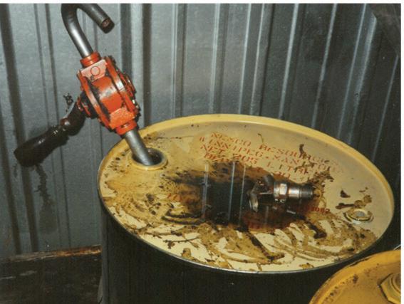
Logic: Contamination control of all lubricants begins with proper storage and handling. Lubricant containers, pumps, and grease guns must be stored in clean, temperature-controlled storage areas and maintained in clean condition, properly labelled for their applicable use with drum bungs properly in place, and new oil should be pre-filtered before use (see Photo 1).
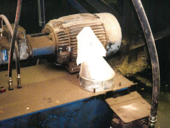
2. Does your plant maintain its equipment in extremely clean condition?
Logic: Plant equipment should be kept as clean as possible. Just ¼ of an inch of dirt and dust on critical components can increase operating temperatures by 10 per cent or more, shortening life by up to 50 per cent. The dust covering an oil reservoir will increase the lubricant temperature by several degrees, promoting overheated lubricant and oxidation potential.
Wire mesh filters located in the reservoir filler caps are inadequate for most applications and should be replaced with a reservoir cap containing a four to six micron-rated filter. The illustration may be considered acceptable conditions, but this system or one or more of its components will fail prematurely and equipment reliability will be shortened resulting in costs that could have been avoided. Note the cloth-covered funnel left on the reservoir (see Photo 2).
Photo Credit:
L. (Tex) Leugner
/ Kesu01 Getty Images (top)
Photo 1
Photo 2
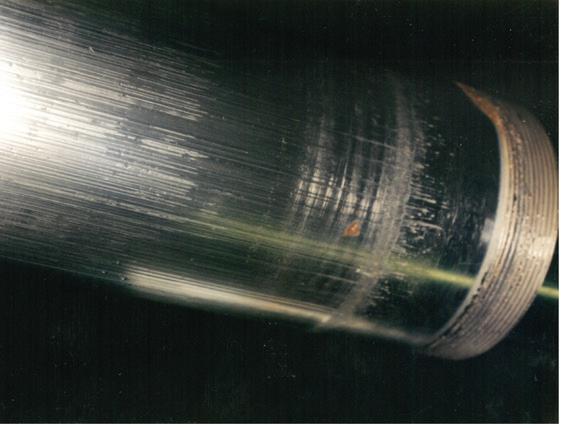
3. Does your plant correct all oil leaks immediately?
Logic: There is clear evidence that if oil can escape past hydraulic seals, contamination of dust, dirt, and water will be drawn in when cylinder rods retract. Note the scoring and rust discolouration on the cylinder rod pictured in Photo 3. Oil leaks, no matter how small or seemingly insignificant, are sources of “machine killer” contamination.
4. Does your plant select and use the effective oil filters?
Logic: Filters must meet or exceed the OEM's standards and should be selected based on the system's flow rates, operating pressures, filter media type, surface area, pore size, micron rating, and bypass valve opening pressure. If the bypass valve opening pressure is not adequate for the system pressures, sudden or frequent pressure surges will permit unfiltered oil to flow during the time the valve is open, a frequent cause of premature component failure.
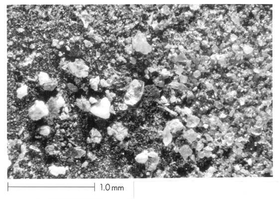
The terminology varies, but many systems now call for side stream/bypass/ kidney filtration systems that will ensure filtration at all times. These filters are mounted in parallel to the primary filter and have ratings as small as four, six, or eight microns and contain no bypass valve, thus ensuring that contamination is mitigated or eliminated completely. Proper filter selection is essential to properly control contamination frequently found in industrial machinery. The three images at right picture case histories that have confirmed excessive levels of contamination using ASTM membrane filtration patch tests and corresponding photography (see Photos 4, 5, and 6).
Photo 4: Contamination in new oil taken from a drum with magnification x 500 illustrates that pre-filtering of new lubricants is recommended and encouraged.
Photo 5: Contamination found in a hydraulic system with magnification x 500 where particle sizes range from sub-micronic to 100 micrometres.
Photo 6: Contamination found in a pressurized geardrive with magnification x 500 where particle sizes range from sub-micronic to over 200 micrometres.
contamination control with the application of effective filtration would have prevented the catastrophic failures illustrated in Photos 5 and 6. This cleanliness standard measures and monitors contamination in the four, six, and 14 micron particle sizes in industrial recirculating lubrication systems. These results are then converted to ISO cleanliness standards described in the chart below.
Typical Recommended Acceptable Contamination Levels by Machine Type and Pressure Ranges
Silt-sensitive servo control systems in laboratory or aerospace systems with pressures of 5000 psi or higher.
High pressure, low tolerance machine tools, and hydrostatic systems with 4500 psi.
High quality, reliable bearing and gear systems in general machine requirements.
Medium pressure, medium tolerance systems. General machine and mobile equipment.
Low pressure, low temperature systems. Heavy industrial applications with large clearance tolerances.
It is virtually impossible to provide a specific ISO cleanliness rating requirement for any piece of industrial equipment. The chart provides guidelines for operators of industrial recirculating lubrication systems. Remember, the smaller the numbers, the cleaner the lubricant. A sound recommendation is to follow the equipment manufacturer’s guidelines; for example, Solar Turbines specifies oil cleanliness be maintained at 16/14/12.
6. Does your plant use the correct analysis program to monitor water contamination?
Logic: Water is a contaminant that can have a devastating effect on certain equipment types and components. As little as 250 ppm of water in equipment like turbines and hydraulics with turbulent or high oil flow rates may cause foaming, particularly if other contaminants are also present.
In systems with bronze or brass components, corrosion can result, particularly where temperatures are abnormally high. As little as 500 ppm of water in some gear drives can reduce rolling element bearing life dramatically. If water is a continuing contamination problem, a Karl Fischer water analysis should be a regularly scheduled monitoring technique. MRO
5. What oil analysis technologies does your plant use to effectively control or mitigate contamination?
Logic: Wear particle analysis by spectroscopy is useless when monitoring contamination particles are larger than approximately six microns. Regularly scheduled contamination monitoring by ISO standard 4406 and subsequent
L. (Tex) Leugner, the author of Practical Handbook of Machinery Lubrication, is a 15-year veteran of the Royal Canadian Electrical Mechanical Engineers, where he served as a technical specialist. He was the founder and operations manager of Maintenance Technology International Inc. for 30 years. Tex holds an STLE lubricant specialist certification and is a millwright and heavy-duty mechanic. He can be reached at texleug@shaw.ca.
Photo 3
TYPES OF CONDITIONBASED MONITORING
BY PETER PHILLIPS
Years ago, I wrote a vibration analysis article: It all started with a screwdriver (www.mromagazine. com/features/it-all-started-with-a-screwdriver/). It explained the evolution from using a screwdriver in the 1950s to assess the mechanical health of the Canadian Armed Forces Sea King helicopter and how they moved to early vibration analysis tools for condition-based monitoring (CBM). Now, many years later, monitoring the health of equipment is a sophisticated process, one that most industries are embracing.
CBM is a type of predictive maintenance that involves using sensors and other measurement tools to measure the status of an asset over time while it is in operation. The data collected can be used to establish trends, predict failures, and calculate remaining life of an asset. Since failures can be detected early and downtime is avoided, CBM can reduce the overall cost per unit of a product.
Unlike preventive maintenance, where maintenance operations are scheduled based on equipment-specific knowledge, statistics, and internal or regulatory requirements. the predictive one relies on monitoring the operational state of the equipment and the evolution to scheduling maintenance based on equipment condition.
Many maintenance staff in process industries have a complex job. They must constantly seek to balance the opposing requirements of maximizing production and machinery uptime while simultaneously minimizing unplanned downtime, while operating within a fixed maintenance budget.
Traditionally, processing plants and non-manufacturing facilities have scheduled maintenance plans for all machines that directly affect production or critical facility systems. However, CBM has proven to be a more effective mainte -
nance strategy when applied to critical equipment and safety-related situations where there is potential danger to the tradesperson performing the machine inspections.
CBM comes in many different applications. The first type of CBM that comes to mind is vibration analysis; however, today and at the onset of Maintenance 4.0, many more options are at our doorstep.
Let’s have a look at what’s available.
Vibration Monitoring
Vibration monitoring is probably the most popular and broadly used type of CBM. This is primarily due to its versatility; most machines regularly produce or experience at least some level of vibration, making this type of device an excellent choice for companies with many different machines to monitor.
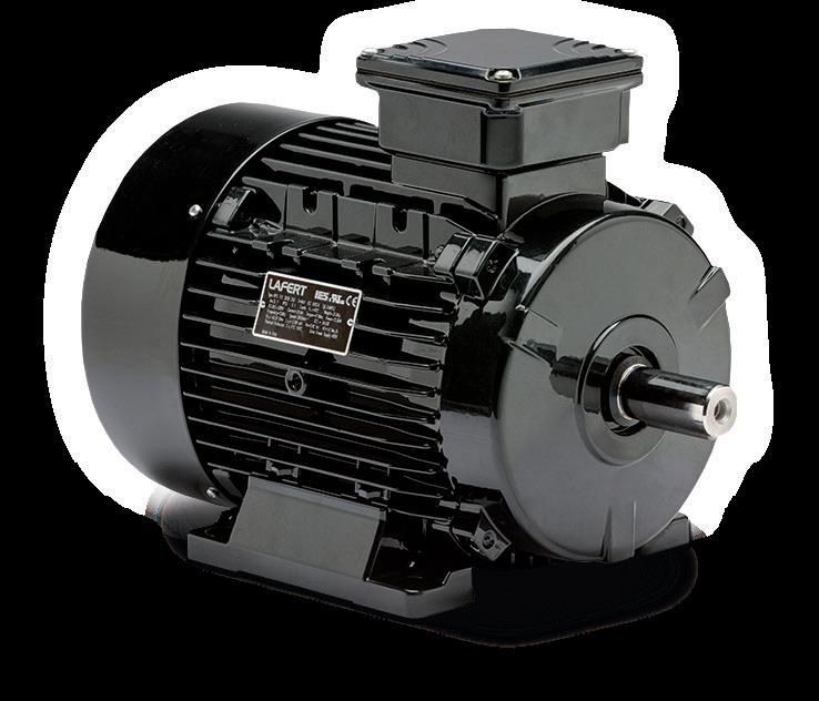
Typically, a vibration monitoring device is attached in some manner to the casing or outer part of the machine. As rotating or otherwise moving parts within the machine perform their jobs, vibrations occur,. These vibrations are picked up and catalogued by the monitoring hardware, typically via accelerometer technology. Vibration analysis is the primarily recommended form of CBM for any machine with rotating parts such as pumps, motors, engines, fans, blowers, and many others. In addition, vibration monitoring devices are extremely effective in detecting misalignments of gearboxes and vibrations in many types of bearings such as the pillow box.
Sonic and Ultrasonic Monitoring
If strange vibrations are the No. ! indication that something is potentially wrong with a machine, then strange sounds
Photo Credit: ipopba Getty Images
are certainly No. 2. Worn, broken, damaged, misaligned, or otherwise improperly functioning parts can make any number of odd sounds. These sounds have been described as grinding, screeching, cracking, and creaking. Sonic CBM devices measure and detect these sounds and then provide an alert that the machine should be inspected or maintained.
The signals monitored by an ultrasonic device are expressed as data using the unit decibels per microvolt (dBuV). Since ultrasonic monitoring focuses on both sonic and electrical elements of machinery, it is capable of detecting not only mechanical failures but also electric failures. Ultrasonic monitoring is highly accurate and, like vibration monitoring, is able not only to identify potential failures early but also to narrow down and specifically pinpoint which parts are in danger of failing.
Lubricating Oil Analysis and Quality Monitoring
Many types of equipment and machinery use some type of lubricating oil to keep their parts moving smoothly and prevent harsh rubbing or impacts between small, delicate elements. These oils must be carefully observed due to high risk of failure and are an excellent indicator of the equipment’s overall health. For this reason, devices have been created that analyze the contents and composition of lubrication oils and provide extremely detailed data, usually via software.
There are currently a number of different oil analysis devices available, as several methods have been developed that are effective in determining the health of the oil. A scanning electron microscope can be used to take a picture of
oil samples in order to obtain close-up views of suspended debris or particles.
Spectrographic oil analysis identifies the chemical composition of the oil at various times throughout the monitoring cycle and provide alerts if unusually high amounts of certain elements or metals are present. Wear debris detection sensors utilize similar methods but focus specifically on the detection of metal particles and the relative proportions of ferrous (iron-containing) and non-ferrous metals present in the oil.
Thermographic (Temperature) Monitoring
Temperature is another common indicator that something may be wrong with your machine. Many components, especially moving parts, tend to give off unusual amounts of heat when they degrade. Heat can also be a warning sign that too much friction is occurring, which can be a sign of misalignments or parts rubbing against one another.
Thermographic CBM devices measure variations in temperature across the surface of the machine to detect areas in which unnatural amounts of heat may be being emitted. Since thermographic devices are especially effective at detecting failures related to rotating parts, they are often used in combination with vibration monitoring hardware, especially on larger machines with many small interconnected elements.
Current and Voltage Monitoring
As some of the above-mentioned devices are primarily fo-
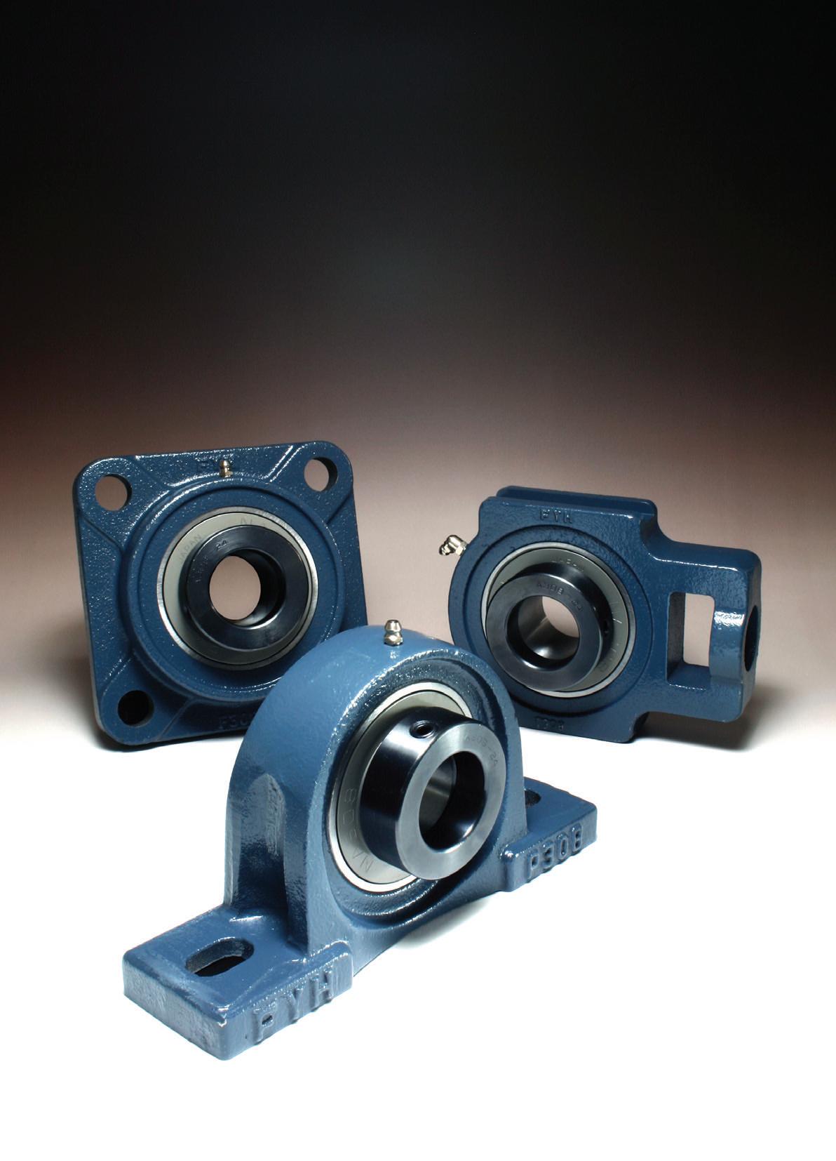
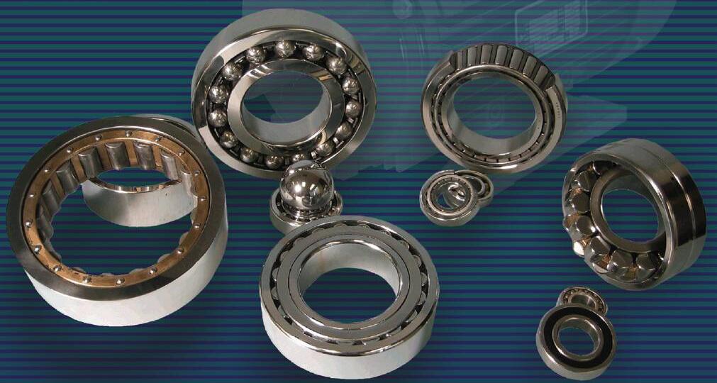
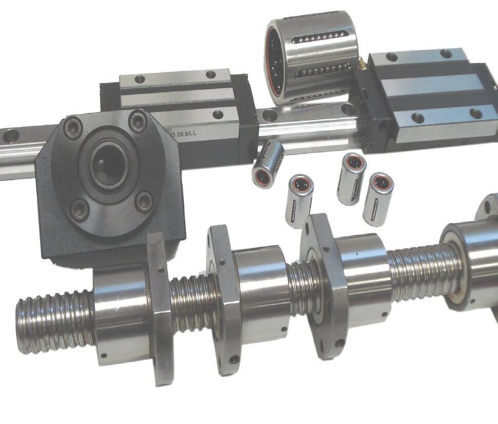
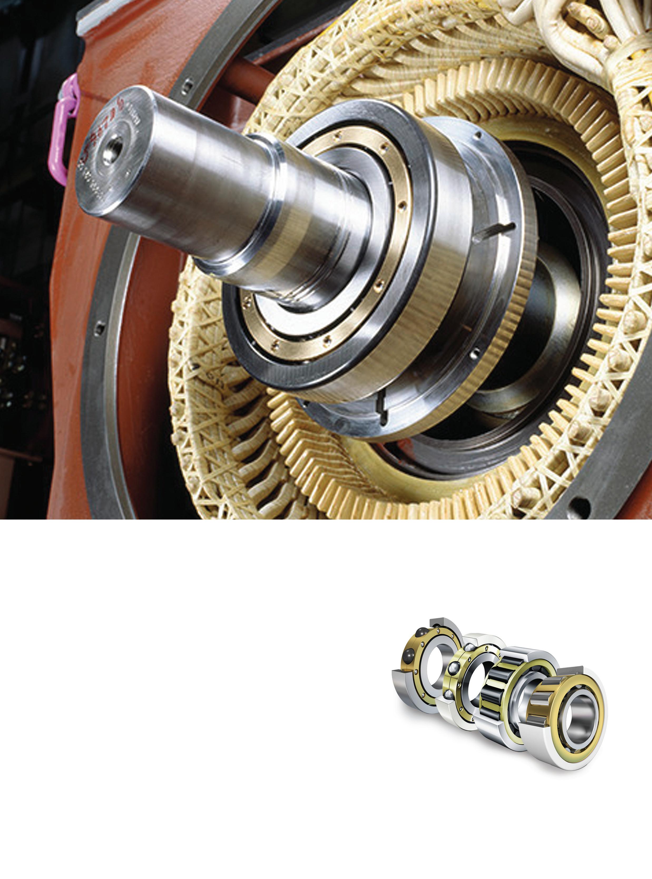
The World of Bearings and Power Transmission...
Photo
Credit: Kinwun Getty Images
cused on detecting mechanical failures, additional hardware has been developed, which specifically focuses on electrical failures. These devices typically measure electrical currents running through the machine and test for unusual voltages.
Current and voltage monitoring devices can detect imbalances in the electrical supply situations in which the machine is receiving too much or too little electricity to function properly, or if something has disrupted the flow of electricity or broken or disrupted any circuits. Some current monitors can also detect specific types of mechanical failures, such as bearings or other rotating parts that are beginning to fail.
The CBM devices described above are only the most popular and widely used of the many varieties currently available for use. Practically every parameter, property, or quality of a machine can be monitored and will indicate at least something about its current health and performance. Therefore, it is impossible to list every type of CBM device currently being manufactured or used.
Benefits of CBM
While each type of CBM device possesses its unique advantages, a number of universal benefits come with the implementation of a successful CBM strategy. They are too numerous to list entirely, but frequently include:
• Extended lifespan of machinery, as collecting data can lead to improvements, which decrease the risk of future failures;
• Saving money over time due to not performing maintenance too frequently or having to replace completely destroyed parts due to undetected failure;
• Employees who possess a greater familiarity with and understanding of the machines that they operate;
• Decreased health and safety risks due to failures being prevented before they occur;
• The decrease or complete elimination of both planned and unplanned downtime, as CBM devices can collect the necessary data while the machines are running; and
• An overall more efficient and successful production process due to the elimination of downtime as well as a significantly lowered risk of producing deformed, damaged, or otherwise unusable parts.
CBM offers myriad benefits, providing early warnings of potential serious failures, reduction in unplanned downtime, reduction in maintenance costs, and support of ongoing reliability and risk reduction with fewer inspections at heights, and confined and remote assets. A new breed of low-cost, easily installed CBM systems can provide these benefits without the high upfront cost and inherent complexity of traditional CBM. Gone are the days of the screwdriver, and soon the days of using the human senses of look, touch, smell, and listen to assess equipment will be in the history books as well. MRO
Peter Phillips is the owner of Trailwalk Holdings Ltd., a Nova Scotia-based maintenance consulting and training company. Peter has over 40 years of industrial maintenance experience. He travels throughout North America working with maintenance departments and speaking at conferences. Reach him at 902-798-3601 or peter@ trailwalk.ca.
CANADIAN LEXUS INVESTS IN OPERATIONS
BY MARIO CYWINSKI
In 2019, Toyota Motor Manufacturing Canada (TMMC) announced that the Lexus NX and NX Hybrid SUVs would be manufactured at its Cambridge, Ont. plant beginning in 2022. The announcement brought dignitaries, Prime Minister of Canada Justin Trudeau; Christine Elliott, Deputy Premier of Ontario and Ontario Minister of Health and Long-Term Care; and TMMC employees to the facility.
“Building on our recent Toyota RAV4 announcement and our recent facility modernization investments, we are excited to announce that TMMC has been selected to produce the popular Lexus NX and Lexus NX Hybrid models for
the entire North American market,” said Fred Volf, President, TMMC.
The award-winning facility, which most recently won a platinum award for its North Plant (Rav4) and a bronze award for its South Plant (Lexus RX) from J.D. Power’s 2019 Plant Quality awards, began producing Lexus vehicles in 2003, becoming the first facility outside of Japan to do so. It has produced over 1.3 million Lexus vehicles since.
“The Cambridge plants have historically performed extremely well, and the data would support the view that they are among the most consistent in North America,” said Dave Sargent, Vice-President of Global Automotive, J.D. Pow-
er. “Everyone at the plants should be very proud.”
Lexus Canada is indeed proud, as it took a group of automotive journalists on a tour of the North and South plants in Cambridge, as well as a drive around the area in all-new 2020 Lexus SUVs, including the made-in-Canada RX.
The Cambridge plant has five common (or shared) facilities for both North and South: plastics, press, facilities, test track, and marshalling yard. But the North and South plants each have their own assembly, paint, and welding. Combined, the plants are 321,940 square/metres, and sit on 161.9 hectares of land. In total, TMMC employs over 8,500 people at its three plants.
Moving away from the plant and to the vehicles that were driven on the media event, we look at the GX, RX, NX, and UX that were available.
Beginning with the RX, it has exterior changes to the grille, LED headlights, taillights, wheels, and colours. On the inside, it has new colours are available, and a phone holder is added. The remote touch is updated and now comes with a touchscreen as well. Rounding out the updates is a kick sensor power tailgate, paddle shifters, enhanced steering, updated suspension, and additions to the Lexus safety system.
The RX is fully connected, too. It offers the Lexus App, which allows for the driver to see fuel level, odometer
Photo
Credit:
Mario Cywinski (vehicle photos), Paul Giamou (plant photos)
reading, and positioning of windows and roof on their mobile device. Enform remote, by way of the Lexus App, can also lock/unlock doors, find the vehicle, and remote start/stop the vehicle. Android Auto, Apple CarPlay, and Amazon Alexa capabilities are also part of the RX package.
“The RX is the original luxury crossover, the one that started it all, and has always offered a versatile blend of style, substance and performance. For 2020, we’ve redesigned the RX to deliver even more of what has made it a favourite year after year, with Canadian luxury buyers,” said Robert Tsang, Director, Lexus Canada.
The GX460, which is the biggest member of Lexus’ lineup, offers a new grille, full LED lighting, minor exterior styling changes, new wheel and colour options, updated steering wheel, and 360-degree camera. The GX was put through its paces at an off-road course during the drive.
Also, part of the drive was Lexus’ second bestselling vehicle and the one coming to TMMC in 2022, the NX (which comes in NX300 and NX300h). Rounding out the lineup was the smallest of the Lexus’ SUVs, the UX (also available in hybrid form).
Going forward, Lexus Canada will be building its top two bestselling SUVs in Canada. This will be not only for the Canadian market, but also for the North America market, as the vehicles are sold here and across the continent. As talk of a contracting automotive manufacturing sector in Ontario continues, Toyota Canada, by way of TMMC, is continuing to invest in its plants in Southern Ontario, bucking the trend of plant closures and cuts. MRO
Mario Cywinski is the Editor of Machinery and Equipment MRO magazine, a member of the Automobile Journalists Association of Canada, and a judge for Canadian Truck King Challenge. He has over 10 years of editorial experience and over 15 years of automobile industry experience, as well as small business industry experience.
CONDITION-BASED MAINTENANCE WILL NOT STOP YOUR MACHINES FROM FAILING
BY JOHN LAMBERT
The ultimate goal for anyone in industrial maintenance should be to gain the optimum full life of machine assets. To do this, plants need to make changes to the current maintenance processes or at least the way many of them are doing things. A lot of companies have some variation of a condition-based maintenance (CBM) program but are scratching their heads as to why they still get machine failures.
They are not wrong in performing CBM, but that alone will not stop their machines from failing.
Let me explain why condition monitoring works. The premise behind CBM is that most failures give some warning that they are about to occur.
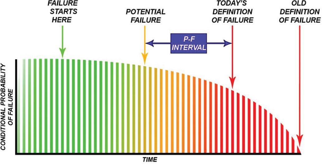
The P to F Interval
This warning is called a potential failure and is defined as an identifiable physical
condition, which indicates that a functional failure is either about to occur or in the process of occurring.
Functional failure is defined as the inability of an item to meet a specified performance standard. The P to F interval is a well-known illustration (see Figure 1).
There are many different techniques to measure and detect potential failures. For instance, if you had a slow-turning gearbox, you may use oil analysis. The most popular instruments to measure potential failures are for vibration, ultrasound, oil analysis, and temperature.
The sooner a potential failure can be detected, the longer the P-F interval can be. Longer P-F intervals mean that inspections need to be done less often, and more time is required to take whatever action is needed to avoid the consequences of the failure. The bottom line is, we take measurements and monitor them over time. If they change, then we react to the change.
Does Performing This Type of CBM or Condition Monitoring Work?
Yes, since you can avoid downtime and save money. Failure comes in many forms and there are many ways to combat it. If you detect the potential failure early enough (and it can be months before the actual failure), it means the breakdown can be avoided. You can schedule an outage to do a repair or maintenance. It’s not a breakdown because the machine hasn’t stopped, and it’s not downtime. This is cost avoidance and the plant can save on the interrupted loss of production because of downtime costs. Avoid the downtime, control the outage, and schedule the maintenance work. It’s a win.
Think about secondary damage. The seal might go in a gearbox and costs (costs are estimates) $1,000 to replace. If you don’t catch it and the bearing becomes contaminated, it becomes an overhaul of the gearbox for $5,000. But if the bearing seizes onto a shaft, now you have to replace the shaft and more.
The cost of secondary damage can be huge; therefore, condition monitoring does work and, if done right, saves time and money. However, there's a problem with condition monitoring, and it's the same with predictive maintenance: machine failure.
Root Cause Analysis and Defect Elimination are a Must
The definition of insanity is “to do the same thing over and over and expect a different result.” If we just keep replac-
Figure 1
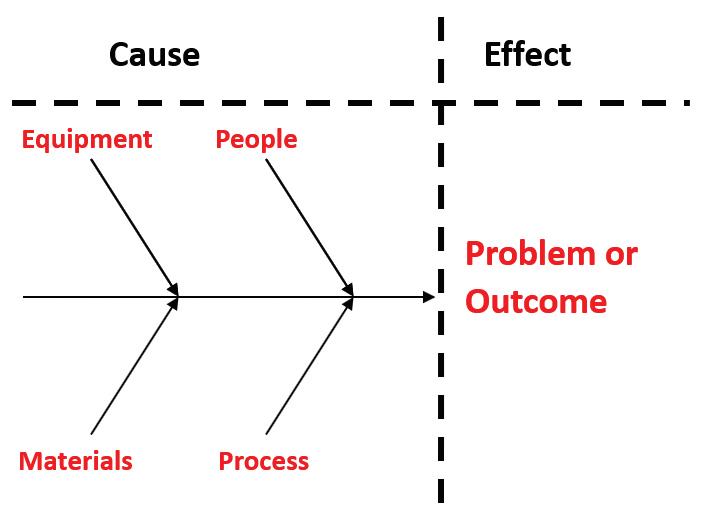
ing bearings and don’t figure out what’s causing the failure, are we crazy? Are we guilty of only repairing the effect and not finding the cause? To only fix the fault/effect is reactive maintenance. A CBM program or any program needs a defect elimination process. This is usually done through a root cause analysis, which is the process of defining, understanding, and solving a problem.
This fishbone diagram (below) is a basic tool used in root cause analysis. We know that the “effect” is that the machine is down, but what is the true “cause” of the failure.
The process was to set up a cross-functional team to brainstorm the cause of the failure. You must make sure that you have people who have direct knowledge of the process being examined. A stepby-step process is then needed to drill down in order to find the true cause of the failure.
This was just one tool used. We can also use the "Five Why." Simply to ask the question why enough times until you get down to the root cause of the issue. Of course, don't limit yourself to asking only five questions; ask as many as necessary. These are only two of the tools that are available; others include failure modes and effects analysis (FMEA). Whatever you use, ensure you do defect elimination as part of your maintenance processes.
Defect elimination is the removal of that cause, which will give you a longer life of your machine assets. The idea is making sure “you fix forever, rather than forever fixing.” Therefore, when something fails, you make sure it does not reoccur, over time you reduce the number of failures and increase your uptime. After defect elimination, whether you’re overhauling, repairing, or redesigning, you are reinstalling the machine. For this you need to implement precision maintenance skills and techniques.
Precision Maintenance
Precision maintenance is simple; it means to work to a recognized standard. A set of
tolerances that you and your team agree on. The tighter the tolerance, the better the result. However, you cannot have a tolerance that cannot be measured.
Precision maintenance means “upskilling” your people. Getting the right tools and the right training. It's machinery acceptance standards, precision balancing, alignment, base flatness standards, and the removal of machine stress.
More importantly, it’s commissioning to a standard and documenting the process. The answer to the question why that was asked in root cause analysis above is usually found in precision maintenance.
Controlling Factors in the Life of a Machine
1. Design/Redesign
A machine's design can have an effect on the machine’s life. However, in maintenance, very often we have to live with the design we have been given. If it's a pump that was underdesigned for the application, the pump would begin life in a functional failure state because it does not meet requirements. Therefore, the design has to be done right; otherwise, the inevitable redesign is done. A review of the machine’s design should be a must in any breakdown analysis.
2. Overhaul/Repair
A machines is overhauled many times throughout its life. It's extremely important that it be done correctly. Many companies will contract this work out, because they do not have the facilities to do the work correctly, as one of the biggest issues during overhaul is contamination. When a machine is overhauled, the most important aspect is that the OEM specification for machine fits is maintained. The goal is to make the machine new again.
3. Installation
Installation is the key. It's the most
critical thing for all machines. A well-designed machine or a well overhauled machine can be ruined with poor installation practices. The installation must be done to a standard such as the ANSI/ASA S2.75-2017/Part 1 or the OEM specification.
4.
Commissioning
Commissioning is actually a continuation of the installation. In fact, it should start with the review of the installation documentation. It should be done by another group, other than the group that did the installation, such as the reliability group. Each machine is different, so we cannot publish a list of what to do, but all of the OEM operation procedures should be followed. When the button is pushed to start the machine, this is where you should be taking measurements for thermal expansion (offline to running) so we know if a correction is necessary before putting the machine into service.
When the machine is online, different parameters should be measured, such as temperature, sound, and vibration, as part of your CBM program. These measurements are the benchmarks used to compare the new measurements taken throughout the life of the machine. Changes from these results mean the machine is deteriorating. However, if you have done a good job at understanding the root causes and using the precision maintenance techniques in the areas that you can control, this should be because the machine is worn out and has had a good long life. MRO
John Lambert is the President of BENCHMARK PDM. He can be reached at john@ benchmarkpdm.com or by visiting the BENCHMARK PDM web site at www. benchmarkpdm.com.
MAINTENANCE 4.0 VS CMMS
BY PETER PHILLIPS
Maintenance 4.0 is synonymous with Industry 4.0 and Factory 4.0 and is talked about everywhere in the maintenance community. Its name was given based on the current trend in automation and data exchange within industry technologies. They include the industrial internet of things (IIoT), wireless sensors, cloud-based computing, artificial intelligence (AI), and machine learning.
How did we arrive at Industry 4.0? Let’s have a quick history lesson. Industry 1.0 refers to the first industrial revolution. It is marked by the transition from hand production methods to machines through the use of water and steam power. Industry 2.0, the second industrial revolution, was made possible by extensive railroad networks and telegraph, which allowed for faster transfer of goods and ideas. The third industrial revolution, or Industry 3.0, occurred after the Second World War and was also called the digital revolution. This involves the use of computers and other digital technologies in the production process.
Maintenance 4.0 is a machine-assisted digital version of all the maintenance activities we have been doing for years to maintain the equipment in the best state of reliability. It is the next progressive step for maintenance departments to take and adopt to modern industrial technologies.
For example, traditionally skilled technicians were sent out to collect vibration readings on pumps, motors, and gearboxes and manually entered the readings into a maintenance program, our computerized maintenance management system (CMMS). In Maintenance 4.0, the technician no longer wastes time going out to collect the data; instead, the readings are gathered by remote sensors that tie directly into a digital system, which can analyze the data and take the appropriate action. The system might report a problem by setting off an alarm, stopping the process, or creating a work order.
Examining the Effects of the Maintenance 4.0 Revolution on the Current CMMS
For several decades, we have depended on CMMS to manage and generate preventive work orders, to record reactive work, maintain equipment and inventory records, and keep work order history on equipment. Inputting of data is a manual pro-
cess and analysis of breakdown data is a labour-intensive exercise. Technicians need to return to the maintenance shop to interact with the CMMS to process their work orders, look up parts inventory, and to research equipment documentation.
In Maintenance 4.0, this is all changing, and CMMS providers are working hard to catch up and to adopt their software to the new technology. Instead of collecting data points from several sources separately and trying to connect the dots, the new generation of CMMS will need to connect to many industrial devices like sensors, equipment monitoring software, safety systems, and other digital technologies, then analyzing the data and triggering the actions to address the problem.
CMMS are not as far behind as you might think. Many software providers are quickly adapting to the new revolution and digital connectivity between multiple systems. One example is the mobility of CMMS. Instead of returning to the maintenance shop to interface with the maintenance software, tablets are now being deployed with a CMMS application that is carried out to the factory floor.
Technicians carry their work orders directly to the equipment where the work order is executed and all the data is entered immediately. Follow-up work orders can be created on the spot. Pictures can be taken of the problem and fed back directly to the CMMS. If parts are needed, real-time inventory levels are available. Tablets can scan barcodes or QR codes that have been applied to the equipment and display equipment documents, manuals, drawings, vibration readings, BOM (bill of materials), and more.
Functions Future CMMS Will Need
In Maintenance 4.0, a CMMS needs to be able to connect to digital devices like sensors, where vibration, temperature, amperage and other readings are recorded. When they are outside predetermined values, the CMMS sets an alarm to alert the maintenance department and create a work order.
Other software, like WINCC, SCADA, and Wonderware, that monitors the production process and equipment, needs to be linked to the CMMS. These programs continuously scan the status of the equipment like temperature, amperage, vibration, and many other parameters and need to link to the CMMS.
Photo Credit: ipopba Getty Images
Production scheduling software needs to integrate with the CMMS, so work orders can be easily scheduled when the equipment will be out of production service, saving the maintenance planner valuable time scheduling work.
When it comes to reporting the new Maintenance 4.0, the CMMS has to produce top-of-the-line KPIs (key performance indicators). Everything from detailed work order completion rates, to mean time between failures, to when and what needs to be done on the equipment. Maintenance managers need comprehensive spending reports that integrate with financial software. The CMMS KPIs need to be available in histograms, pie charts, and comparison reports with the ability to drill down into the layers of data to view specific details.
This integration and holistic approach comes with its share of challenges for companies and their current CMMS. Can it support the new technology, or does it need to be replaced or upgraded? It’s not just a matter of purchasing the new technology and flicking a few switches. Putting all the right tools, processes, and systems in place takes time and resources. CMMS data needs to have structure and naming conventions for master data. Many past CMMS bad habits will not work in the new systems; CMMS garbage in will result in some pretty useless data out. We need to cultivate new habits through strong processes and procedures in order for Maintenance 4.0 to be successful. Help will be needed for some of the technicians with adapting to the new way of doing things.
The bottom line for organizations is, can Maintenance 4.0 help the maintenance teams save money? Will accurate data from multiple sources flowing to and from the CMMS increase reliability? Will it provide a healthy ROI? Will it reduce the cost per unit of what is manufactured?
Let’s face it, the spotlight usually shines brightest on the maintenance department when something goes wrong. They are either blamed for the problem or glorified for saving the day using a reactive approach. This way of thinking devalues maintenance best practices and often rewards poor performance.
This mindset is ready to change with Maintenance 4.0. New tools and methods linked to the CMMS are capable of measuring maintenance activities in minute detail and how
they affect equipment reliability. Maintenance 4.0 is in its infancy, so some industries and CMMS providers are sitting on the sidelines waiting to see what happens. The average manufacturing plant misses 17 days of production every year, costing millions of dollars in lost revenue. The risk of not pursuing Maintenance 4.0 is far greater than the risk of waiting. The CMMS is the key to the implementation and it’s time to start taking steps to explore, evaluate, and determine if you are ready for Maintenance 4.0. MRO
Peter Phillips is the owner of Trailwalk Holdings Ltd., a Nova Scotia-based maintenance consulting and training company. Peter has over 40 years of industrial maintenance experience. He travels throughout North America working with maintenance departments and speaking at conferences. Reach him at 902-798-3601 or peter@trailwalk.ca.
Range of high performance lubricants
WHAT’S NEW IN PRODUCTS
Twin Spring Coupling TSC150
Twin Spring Coupling announced today the release of its TSC150. Its design allows the coupling to do the job of two different coupling technologies in the one. It's a maintenance-free product as it contains no bearings.
TSC150 can handle high speed/low misalignment and has dual spring construction. It can also run at lower speeds and higher misalignment like the industry standard universal joint. It is torque rated to 150 foot/pounds of torque and can run at speeds of up to 3,500 RPM at low degrees of misalignment. www.twinspringcoupling.com
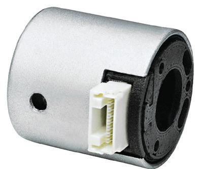
Endress+Hauser’s Liquiphant FTL51B
Endress+Hauser’s Liquiphant FTL51B is available in a full range of variants designed to meet Industry 4.0 requirements, including a mobile communication capability. Operators can communicate with the Liquiphant by
using the SmartBlue app, based on Bluetooth technology, and it provides 24/7 on-site access to all product and diagnostic data for iOS and Android mobile devices. With mobile monitoring, employees can choose a location within 20 metres of the FTL51B to receive the data. Liquiphant displays the status of the level switch via ultra-bright LED on the device or displayed in the SmartBlue app. www.ca.endress.com
Posital Miniature Multi-Turn Kit Encoders
Posital unveiled a fully functional prototype of miniature multi-turn kit encoders for integrated motor feedback. With a diameter of 22 millimetres and a height of 23 mm, they feature a self-powered rotation counter. They cover a multi-turn measurement range and provide digital output. They are rugged and resistant to contamination by oil, dust, or moisture; they offer 17-bit electronic resolution and a multi-turn measurement range of up to 32 bits. Vendor-neutral SSI and BiSS C interfaces are supported. Installation is straightforward and can be done under normal factory conditions. www.posital.com
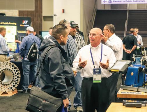
Find Your Facility’s Solution at Reliable Plant 2020
For over 20 years, the Reliable Plant Conference & Exhibition has proven to be the only place to find technical excellence, cutting-edge technologies and proven solutions for the maintenance and reliability industry. For 2020, Reliable Plant is racing back to the city which is famous for bourbon, baseball and the Kentucky Derby.
With an established and global reputation for technical excellence, Reliable Plant brings together key plant and maintenance managers, as well as reliability and lubrication professionals, from across the world.
Spanning four days, Reliable Plant 2020 includes workshops, learning sessions and case studies designed to upgrade the skills and knowledge of attendees. The conference will also feature approximately 130 exhibitors inside the Kentucky International Convention Center. For more information visit conference.reliableplant.com.
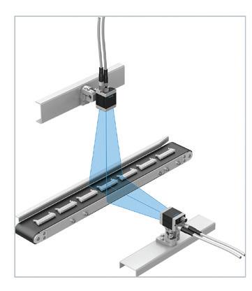
Festo SBRD Smart Camera
Festo SBRD smart camera system covers a dozen fields of analysis, tracking, and verification. The SBRD system has three elements: lightweight, compact high-resolution USB cameras in monochrome or colour with resolution up to five megapixels; a controller with two camera interfaces; and Camera Configuration Studio image processing software. The fanless remote head controller has a dual core processor and PROFINET communications. The tolerance ranges are based on the results data of the recorded images, but manual changes can be made. The software’s CCSxRun tool enables test tools to be parameterized quickly. www.festo.ca
FLIR TG267 Thermal Camera
FLIR Systems Inc. TG267 thermal camera helps inspect equipment and identify problems from a safe distance by visualizing hot and cold spots, from electrical connections to mechanical breakdowns within a temperature range of -25ºC to 380ºC. TG267 adds contact
measurement with a Type K thermocouple probe for temperature readings. It is built around a 160 by 120 FLIR Lepton thermal sensor. TG267 features a multipoint laser pointer and bright LED flashlight. Bluetooth Low Energy technology allows image and data upload to a mobile device. TG267 stores up to 50,000 images seen on the 2.4-inch colour display.
www.flir.com/tg267
Sullair Introduces LS160 Rotary Screw Compressor
Sullair modified LS160 oil-flooded rotary screw air compressor features larger and higher efficiency air end, resulting in greater free air delivery and increased efficiency in LS160 units up to 150 psi. The new air end is larger in size. The modified LS160 also includes a 25 per cent larger low restriction inlet valve. The LS160 Series includes offerings from 125 to 200 hp and 90 to 160 kW.
www.sullair.com
Municipalities to Work With PEMAC to Gain Asset Management Knowledge
The Honourable Catherine McKenna, Minister of Infrastructure and Communities, and Bill Karsten, President of Federation of Canadian Municipalities (FCM), announced that PEMAC has been chosen to work with Canadian municipalities to help them improve infrastructure decisions through stronger asset management practices.
PEMAC is one of the 18 partner organizations selected by the FCM to deliver asset management training activities, including group learning and hands-on training. They will help municipal staff and elected officials gain asset management knowledge and skills.
PEMAC will offer its Asset Management Professional (AMP) certification program to cross-functional municipal teams. This six-course program leads to a Certified AMP designation. Also, opportunities for participants to take the first course in the program, focused on asset management principles and strategic development, which will be offered face-to-face across Canada.
“PEMAC, in partnership with Northern Lakes College, is pleased to offer the Asset Management Professional (AMP) education program to professionals responsible for asset management strategy from municipalities across Canada,” said Cindy Snedden, Executive Director, PEMAC. “Practitioners will have access to the latest in strategic asset management thinking, and gain insight into asset management essentials in the context of ISO 5500x, all while developing the capacity to engage others and build their knowledge and skills.” MRO
PEMAC Appointments
To help support chapters and advance the quality of its programming, PEMAC has added three members to its team.
Mbo Mtetwa has been named as PEMAC’s new Marketing Specialist. He has digital marketing and graphic design experience, which will assist PEMAC in its marketing endeavours going forward.
Russell Zwicker joins PEMAC as a Learning Specialist. He has worked as an instructional designer for 10 years. He will work with the instructors and subject matter experts on curriculum maintenance and development. He has worked for several years in Nova Scotia with the Canadian military, developing training for the Air Force. Zwicker also has extensive experience in e-learning development and workshop facilitation.
Chyan Loyd has been named to the PEMAC administrative team. She brings accounting and bookkeeping knowledge and experience to assist in a bookkeeping capacity. Loyd has six years' experience working for an oilfield company. She completed a Bachelor of Commerce with a major in accounting and a Diploma in Human Resources Management. MRO
New or Improved?
Implementing a new computerized maintenance management system (CMMS) product or relaunching your existing one?
This could be a crossroad that many organizations face at least once in their lifetimes as many CMMS products are evolving to more complex enterprise asset management systems (EAMS), or even asset performance management systems (APMS).
There are many considerations from the product perspective and the organizational side, but the focus should be about the goal of using CMMS. Giving meaning to the utilization of such a powerful tool is paramount to compare your current reality to a future state.
A solid asset management strategy goes beyond maintenance and work management; it encompasses multiple disciplines, including finance, supply chain, inventory control, data management, management of change, quality control, operations, human resources, and every other department. Each will have a role to play in a well-established asset management plan. Having the big picture of an organizational operation, where all departments work together to achieve a common goal, definitively gives a clue about the data requirements and integration flexibility of the CMMS.
Establish a CMMS utilization policy based on your asset management strategy needs, as it will also highlight any strengths or weaknesses of your current product. This policy should list what the fields in the CMMS that are key to obtain the indicators that measure your performance, based on the value that your assets add to your organization. It should also include the information landscape, where you define the different software needed to integrate or interact with your CMMS, to achieve the maximum interoperability of information and technologies.
User feedback certainly is important, so consult your staff to gain firsthand likes and dislikes, functionality reviews, and ratings of the current user experience. Users are the cornerstone of your project; it is people who will embrace or reject the changes. Involving them from the start will give them more sense of ownership over the decisions made and will up the chances of success.
Take your time and include a multidisciplinary team to draft a solid CMMS requirement to evaluate your options; and do not rush the decision. Get your organization ready, and make sure you have change management support in either decision (new or improved) to get the right processes in place to ease the implementation. MRO
The problem: Damage caused by electrical current passing through bearings in electric motors.
The solution: Current-insulated bearings from Schaeffler — including hybrid ceramic or ceramic-coated versions featuring our proprietary Insutect™ coating — that have been engineered to stop stray electric current in its tracks.