ONLINE MARCH 30 & 31, 12 - 3:30


ONLINE MARCH 30 & 31, 12 - 3:30
Speakers include: Siegenthaler, Bean, Miller, Goldie, Bennett, MacNevin
Topics include:
- Air-to-Water Heat Pumps
- Reducing Water Temperature in Existing Hydronic Systems
- Energy Metering
- Selling Hydronics to Builders
- Buffer Tanks
- Snow and Ice Melt


MH4 SYSTEM EFFICIENCY
Flow Energy… Don’t Waste It
Taking steps to streamline and optimize the flow within a hydronic design contributes to the system’s overall efficiency.
By John Siegenthaler
MH8 HEAT EMMITERS
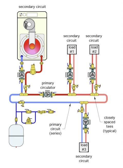
New School, New Hydronic Technology
The recently opened New Westminster Secondary School in B.C. is operating with a lowtemperature hydronic system and efficient heat emitter solutions.
By Cyrus Kangarloo
MH12 BOILERS
Bridge Technology
Ontario-based iGENTechnologies has developed a new combined heat and power boiler.
By Doug Picklyk
CONTROLS Over Controlling
After years of experience, it’s time to share my thoughts on geothermal system design and how we can all create better solutions with more collaboration up front.
By Curtis Bennett
EDITOR
ASSOCIATE PUBLISHER
ACCOUNT COORDINATOR
MEDIA DESIGNER
CIRCULATION MANAGER
PUBLISHER
COO
The session-packed 2021 Modern Hydronics Summit will be held online using a virtual event platform that enables interactive features including live text and video chat.
By HPAC Staff
MH21 EXHIBIT HALL
Modern Hydronics Summit Product Preview
MH24 COVID-19 SARS-CoV-2 and Mutations: What is the Message for Hydronics?
During a pandemic, in a cold-weather climate like Canada, the ability to separate thermal comfort systems from indoor air quality provides an inherent advantage.
By Robert Bean
MH26 PIPING No Torches Needed
The introduction of flexible tubing materials and new press fittings is revolutionizing the hydronics industry in many positive ways. By John Siegenthaler
Doug Picklyk (416) 510-5218 DPicklyk@hpacmag.com
David Skene (416) 510-6884 DSkene@hpacmag.com
Kim Rossiter (416) 510-6794 KRossiter@hpacmag.com
Emily Sun esun@annexbusinessmedia.com
Urszula Grzyb (416) 442-5600, ext. 3537 ugrzyb@annexbusinessmedia.com
Peter Leonard (416) 510-6847 PLeonard@hpacmag.com
Scott Jamieson


Taking steps to streamline and optimize the flow within a hydronic design contributes to the system’s overall efficiency.
BY JOHN SIEGENTHALER
Ask most heating professionals about the energy used by the systems they design or install, and the responses are almost guaranteed to deal with “fuel“ energy (e.g., natural, gas, propane, oil, pellets, etc.) required by their systems.
With the exception of systems using electric boilers or heat pumps as their primary heat source, few heating pros give much thought to the electrical energy used in their systems. Perhaps they view such energy as trivial in comparison to fuel energy. They might regard it as simply a “parasitic” necessity for delivering heat produced by the highefficiency heat sources they install.
That mindset has a historical parallel in the auto industry. Think back to what automobiles looked like in the mid-twentieth century. Many had large exterior “appurtenances” such as out-swinging vent windows, flat-facing mirrors, hood ornaments, chrome trim, massive front ends, and other objects that were part of the auto persona of that time. A 1956 Cadillac Fleetwood weighed more than 5,000 lbs., about the same as a new F-150 pickup. That Cadillac also got about 10.5 miles per gallon.
In that era fuel was relatively cheap and seemingly endless in supply. There wasn’t much concern for increasing mileage by streamlining cars. Those V8
engines with 4-barrel carburetors had the power to overcome the drag. One of the most recognized auto designers of that era, Enzo Ferrari, expressed it well: “Aerodynamics are for people who can’t build engines…”
Today’s cars are very different. Many have streamlined bodies designed to minimize drag. Nearly all are significantly lighter than those of the midtwentieth century. These details are all aimed at increasing fuel mileage.
So why all the discussion of old automobiles? It's because today's hydronics industry, at times, seems to treat the energy used to move heat from where it’s generated to where it’s needed in the building with the same attitude of the mid-twentieth-century car designer. If the heat isn’t moving along fast enough, or the flow path has high resistance, just use a larger circulator.
Every component that has fluid passing through it dissipates head (mechanical energy) from that fluid. The amount of mechanical power required to push flow through a component, or a string of components in a series, can be calculated using the following formula.
Formula 1.
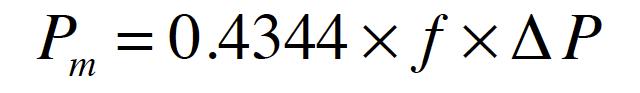
Where:
Pm = mechanical power dissipated (watts)
0.4344 = a constant required by the units in the formula
f = flow rate (gallons/minute)
∆P = pressure drop through the component(s) (psi)
“We shouldn’t treat the electrical energy used by our distribution systems as trivial.”
The higher the flow rate, and the higher the pressure drop, the greater the mechanical power dissipated. Here’s an example:
How much mechanical power will be required to move 120F water at 10 gpm through 120 feet. of 1-in. type M copper pipe? The flow rate is stated, but not the pressure drop. To get that pressure drop you can turn to several sources: tables, formulas, or software.
I like to use the Hydronics Design Studio software for such calculations because it accurately accounts for the changes in fluid properties based on
temperature, which in turn effects pressure drop. Putting the stated numbers into the software yields a pressure drop of 2.4 psi. The remaining math is easy:
determined to be 10.4 watts) by the wire-to-water efficiency of the circulator, as shown in formula 2.
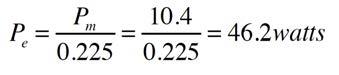
Formula 2. We’ll use this value as a baseline for comparison.
DO “SUBSTITUTIONS” MATTER?
How about if we used 1-in. PEX tubing instead of 1-in. type M copper tubing for this segment of the system, and we change the circulator, if necessary, to ensure that the same 10 gpm flow is achieved?
Changing the pipe changes the pressure drop. The Hydronics Design Studio software quickly returns a pressure drop of 6.24 psi for 120 feet of 1-in. PEX operating with water at 120F and 10 gpm.
This change pushes the mechanical power requirement to 27.1 watts, and the circulator input power (assuming the same 22.5% wire-to-water efficiency) to 120 watts. That’s a significant increase in pumping power. It’s the result of the smaller internal diameter of 1-in. PEX (0.875-in.) versus that of 1-in. type M copper (1.055-in.).
You might be thinking I made up this example to dissuade you from using PEX rather than copper for distribution piping. Not so. Instead, I’m trying to show that what might seem like an “equivalent” substitute (1-in. PEX for 1-in. copper) can have ramifications. In this case it adds significant operating cost over the life of the system.
Although the units on the result are in watts, and most of us associate watts with electricity, understand that this is not the electrical input power required to sustain the stated conditions. It’s the mechanical output power required by the circulator.
We pay for the electrical power input to the circulator, not the output power. To calculate the input power we would need to know the wire-to-water efficiency of the circulator creating this condition.
The efficiency is very dependent on where the circulator is operating on its pump curve. Ideally, the circulator is operating near the middle of its pump curve, where the wire to water efficiency is highest.
If we assume a small circulator with a PSC (permanent split capacitor) motor is operating under favorable conditions (e.g., near the centre of its pump curve), a reasonable value for wire-to-water efficiency is 20 to 25%. Let’s split the difference and assume 22.5%.
To calculate the electrical input power to the circulator in our example, divide the mechanical output power (which we
If we assume that flow passes through this 120 feet of pipe for an average of 3,000 hours per year, and that the electrical energy costs $0.15 per kWh, and that electrical energy costs escalate at 2% per year. The difference in operating cost over 20 years would be $807! That’s just for this 120 feet of 1-in. piping. You won’t pay it, but your customer will.
If you design, install or manufacture hardware for hydronic systems you should be continually thinking about ways to reduce the electrical operating cost of those systems.
Our industry should embrace ways to reduce circulator count. One example would be eliminating “dedicated” primary loop circulators. Those that only push flow through the primary loop, and not the heat source or any load circuits.
Another approach would be using (or creating) heat sources that don’t have high head loss heat exchangers, and thus conserve head energy. In my opinion, a “self-buffering” heat source with very low head loss is ideal. It eliminates the need
Continued on MH6
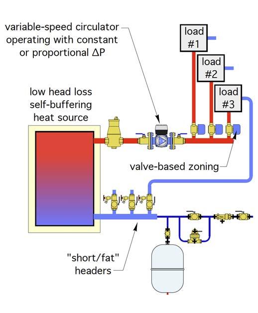
for a buffer tank as well as a circulator between that tank and the heat source.
This approach is likely to cost less (materials and labour) and install faster than using a heat source combined with a separate buffer tank and all the piping, fittings, valves, and circulator between them.
The use of variable speed circulators with integral speed control algorithms used in combination with valve-based zoning rather than dedicated zone circulators is another way to reduce the power demand of distribution systems.
Figures 1 and 2 above show several of these concepts.
We should avoid using excessively oversized circulators and then throttling away their excess head with balancing valves. That’s analogous to driving a car around with the gas pedal pressed down farther than necessary and controlling speed with partially applied brakes.
We should use dirt separators that don’t increase their pressure drop as internal screens load up.
We should use glycol-based antifreeze “judiciously.” The higher the concentration of glycol, the higher the density and viscosity of the solution, and the higher the ratio of viscosity divided by density is, the greater the “drag” as fluid passes through the system.
If your piping layout requires a lot of 90-degree turns, consider using a tube bender to create larger radius bends rather than using standard 90-degree elbows. Larger radius bends decrease turbulence and thus decrease head energy dissipation.
We should also take a close look at heat emitters such as panel radiators, which can operate with design load ∆Ts in the range of 30-36F rather than 20 F. The higher the ∆T the lower the required flow rate, and thus the lower the head loss for a given pipe size.
We should compare the added cost of using one size larger piping, and thus reduced head loss, against the life-cycle electrical energy savings associated with a smaller circulator.
The science of fluid dynamics has been extensively applied in many technologies where a fluid moves across a surface. Compare the planes, cars and boats from the middle of last century to those of today. The shapes are very different, and the reduction in energy use due to decreased drag has been remarkable.
If our charge as hydronic professionals is to improve the overall energy efficiency of the methods and materials we assemble, we shouldn’t treat the electrical energy used by our distribution systems is trivial. Energy, as fuel or embodied in flow (e.g., head), is a terrible thing to waste! <>

John Siegenthaler, P.E., is a mechanical engineering graduate of Rensselaer Polytechnic Institute and a licensed professional engineer. He has more than 40 years experience in designing modern hydronic heating systems. Siegenthaler’s latest book is Heating with Renewable Energy (see www.hydronicpros.com for more information).

AutoFill™ Is the original automatic, fast-filling boiler valve, offering precise pressure control in hydronic systems. Set it and forget it with a simple dial set point adjustment, factory pre-set at 15 psi. The valve combines with an optional ASSE 1012 dual check or ASSE 1013 reduced pressure zone backflow preventer to save time and reduce space requirements. An optional pressure gauge offers local setting indication at a glance. CALEFFI GUARANTEED.

The recently opened New Westminster Secondary School in B.C. is operating with a low-temperature hydronic system and efficient heat emitter solutions.
BY CYRUS KANGARLOO, P.ENG.
Considered one of the largest and most complex school projects in the history of British Columbia, the New Westminster Secondary School opened its doors to students for the first time Monday, January 11, 2021.
It is the second largest secondary school in B.C. and the new educational home for approximately 1,900 students in grades 9 through 12. The facility also serves as a community space for local New Westminster residents.
The project, the largest single school
investment in B.C. Ministry of Education history, has been several years in the making. The original high school, built in 1949, was outdated and found to be in need of seismic remediation. Funding for the project was announced in June 2016, and the $106.5-million contract was awarded to Graham Construction and KMBR Architects in Dec. 2017. Integral Group, a design firm focused on sustainability, was selected to lead engineering and design for the new state-ofthe-art learning facility constructed next to the existing school. Surrey, B.C.-
based Division 15 Mechanical was the mechanical contractor on the project. Designed to create flexible learning spaces, the building hosts several multipurpose spaces and modern shops, along with contemporary fine art and performance spaces. The project also includes community maintenance facilities.
Eunice Doroteo, senior engineer with Integral, began working on the project in 2017, designing the mechanical system using a low-temperature heating water loop. This would most effectively allow the project to achieve energy efficiency goals with the ultimate goal of achieving LEED-Gold certification.
“This job is very important to our team,” said Doroteo. “The children and families of New Westminster have been waiting for it for a long time and we are excited to provide them with a building that serves the whole New Westminster community.”
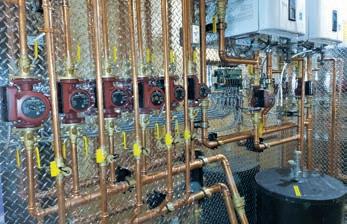
The mechanical system employed uses three large 3,500 MBtu high-efficiency condensing boilers to heat the 16,390-square-metre school. And an air separator removes any air in the system, which serves thousands of feet of hydronic convectors throughout the school.
Low greenhouse gas emissions are very important on this project, and the condensing boilers must be operating with return water temperatures below 100F (38C) to maintain rated efficiencies. Every convector selected for this project was sized with the low return temperature in mind.
There wasn’t an unlimited budget, so the heating solutions also had to be cost effective. The convectors used throughout the school proved to be the answer as they are cost effective while allowing for heat output with low water temperatures.

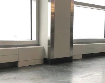
All classrooms use the low-temperature convectors along the perimeter, mounted within a casing, including covers so there is no exposed piping.
In addition to reducing the energy consumption, the units react quickly to internal heat loads. So, when students arrive in the morning, the units ramp up until the desired temperatures are reached. Just as with lighting, where you flick the switch and the lights turn on. It’s the same principle with these lowtemperature convectors in the classroom—there is no reason to heat a classroom when it is unoccupied when you can provide almost instantaneous heat on demand.
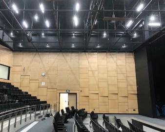
In larger spaces, such as shops and the theater, engineers specified unique unit heaters that operate on the existing lowtemperature heating water loop.
“We wanted a product that fits in a space with extremely high headroom, but the challenge is finding a heater that has enough capacity to make sure that occupants at lower levels would be comfortable,” said Doroteo. “We also wanted
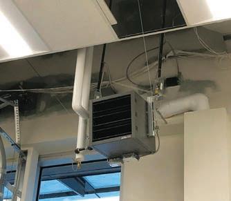
something with a nice finish.”
The unit heater selected features a technology that generates quick, powerful airflow with even temperature distribution. It does this by reducing the return temperature, which reduces stratification and the amount of cold air build-up at the ground level. This means shorter operational times and greater energy savings.
The product would also need to fit the school’s stringent acoustic requirements. This required all of the mechanical equipment to be less noisy. The use of EC motors in the unit heaters means there is very little fan noise along with 90% less electrical consumption when compared to traditional motors.
“The unit heaters installed are the quietest I’ve ever seen in my career,” said Doroteo. “Even though they are shops, they are still teaching spaces. That means when they’re not doing any activity, the teacher is still providing instruction. Having a quiet mechanical system reduces the background noise to facilitate better learning.”
In addition to shops, unit heaters were placed in janitorial closets to prevent pipes from freezing, in weight rooms and art galleries throughout the building. A total of 37 units were used,
The impact of noise on student performance in schools is only beginning to be examined. A study of 500 French primary school students published in the Journal of Urban Health in 2014 revealed that standardized test scores were 5.5 points lower for each 10 dB increase in noise level over the average of 50 dB.
which reduced the amount of space required from similar systems.
At entry and exit ways throughout the school, force flow cabinet style heaters provide individualized room temperature controls.
The facility was initially scheduled to open in September 2020, but COVIDrelated delays that included general workforce reductions caused setbacks along the way. Despite these challenges, the building opened with minimal delay.
“Students deserve to learn in modern and inspiring learning environments, and I am so excited that will now be the case for secondary school students in New Westminster,” said Jennifer Whiteside, Minister of Education in a government release a day after the school’s recent opening. “This new school is so important for our community, and I know that families in New West are thrilled to have a new, state-ofthe-art facility that will benefit students for generations to come.” <>
Cyrus Kangarloo, P.Eng., is the North American Operations Manager of Jaga Climate Systems, designers of low-temperature HVAC solutions designed for a better indoor and outdoor environment. For additional information about Jaga visit jaga-canada.com. Kangarloo can be reached at ckangarloo@jaga-canada. com.


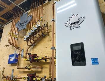
Here are a few of this years entries.
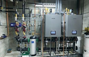
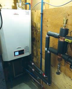
Get your cameras ready. Be a part of Canada’s first ever hydronic installation contest.
Proud of your work? Better than the rest? It’s time to bring it on!
ENTRY IS SIMPLE – send us pics (before and after shots will work best) of your installation. Include a brief description of the particular challenges that you faced with this installation and how you overcame the obstacles to deliver your customers Sweet Heat. This can be a new installation or a retrofit. Submissions are limited to one per contractor. Remember that aesthetics are only one part of the judging criteria. Deadline to enter is March 12, 2021. Show us your problem-solving ability too! The winning entry, and two runners up, will be discussed and announced at the end of the Modern Hydronics virtual Summit (March 30 and 31) by none other than our very own John Siegenthaler and Robert Bean. In addition to having your winning entry shared across our social media channels you’ll also be interviewed by HPAC’s editor and featured on the cover of the August edition of Modern Hydronics –

Ontario-based iGEN Technologies has developed a micro combined heat and power (CHP) boiler to provide a resilient option for home heating.
BY DOUG PICKLYK
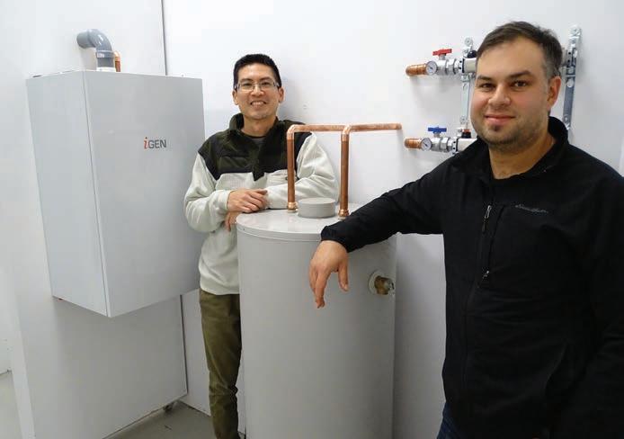
We like to consider ourselves a technology company—not like an Apple or Facebook—but relative to the HVAC industry, we see ourselves on the high-tech side,” says Patrick Lai, one of the co-founders of iGEN Technologies, a company that has developed a unit, about the size of a typical wall-hung boiler, that will provide heat for a modest-sized home and generate enough electricity to be self-sustaining.
The two founders, Lai and Michael Chatzigrigoriou, are mechanical engineers who initially met when working together at a small HVAC consulting firm. The two joined forces to launch their own HVAC consulting engineering business, which then led to forming iGEN Technologies in 2012. “We literally started in Michael’s garage” notes Lai, the classic high-tech origin story.
The initial driving force for Lai was to create a technology that would enable homeowners to get off the grid. Based on their combined engineering backgrounds and specific HVAC knowledge they wanted to build an appliance that could be practical and affordable.
As air conditioning units have become ubiquitous, Lai explains that if you take the typical components of an air conditioner (compressor, heat exchanger, and refrigerant piping), and you run the process backwards—not reversing the flow
like a heat pump but actually apply high temperature heat to the process—you can get power out.
He draws a comparison to how large nuclear generating stations operate, where inside you have a steam Rankine cycle and high-pressure steam drives a turbine connected to the generator which outputs electricity. The steam then runs through a condenser, returns to liquid form, and the closed-loop process continues. Essentially, they’ve reproduced the Rankine cycle inside a gas-fed module to produce heat and electricity for a house (see sidebar: “How it Operates”).
From 2012 to 2017 the duo conducted a lot of research and development, moving out of the garage and into an office space in Markham, Ont. After initial gas furnace-like prototypes, they looked at the trends leading towards high-efficient hydronic heating solutions and began experimenting by placing their heat and power module within the casing of a tankless water heater and coupling that with an air handler.
Then, in April 2018 iGEN Technologies acquired assets of UK based Flowgroup, including patents and inventory related to that company’s micro combined heat and power (micro-CHP) boiler technology.
“It was a deal that made sense for us,” says Lai, “Because they were manufacturing something very similar to what we were doing, the only difference was they had a 10-year head-start on us.”
As he explains it, the Flowgroup’s business model was to maximize the electrical power output of their units, but that solution didn’t take off. Although Lai’s initial drive was to provide home owners with energy independence, now it shifted to generating heat first, power second.
“We’re not going to replace the utility, we’re simply supplementing a home’s power supply,” he explains. What they are offering is a product which will be resilient enough to provide a self-sustaining heat source for homes in the case of power failure, and do it efficiently.


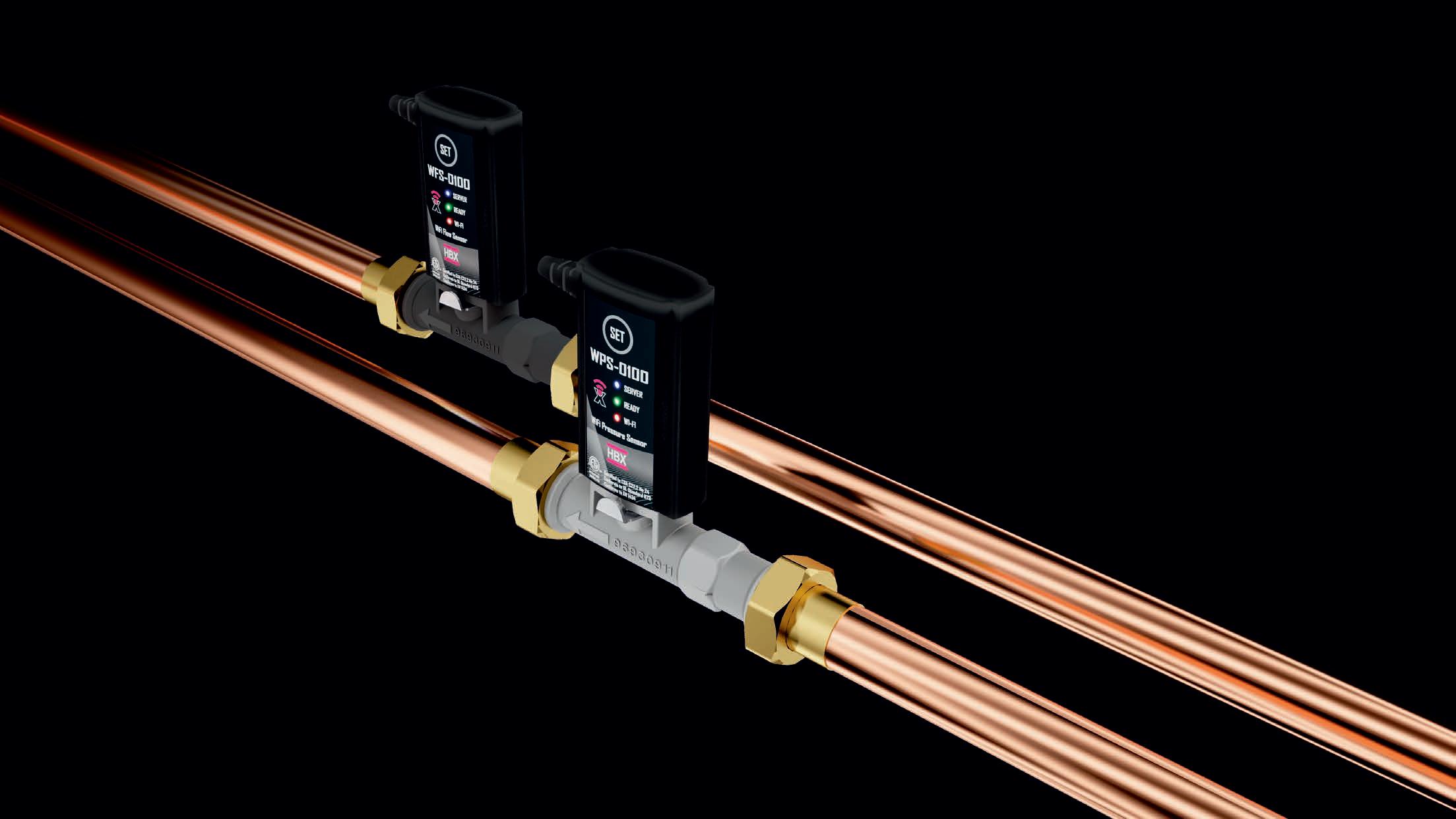
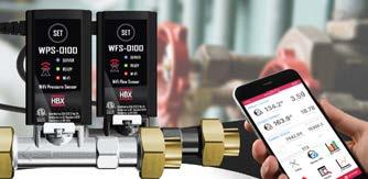
Sensorlinx is designed to measure energy used or transferred in a liquid heating application including HVAC, Solar and Geothermal. The sensors can be used individually to track system flow, temperature, pressure and allows for accurate BTU measurement up to 105 GPM when the sensors are used in conjunction. The sensors also allow for system balancing, triac output for relay operation, and remote system monitoring and configuration with the Thermolinx Hydronic Network.

“Our solution fills a gap,” says Lai. “Resiliency is a key value proposition, but there are other benefits as well. Because the unit is generating electricity when it’s operating you’re not buying that power from the grid, so depending on where you live there are potential utility savings if you’re using lower-cost natural gas to offset high-priced electricity.”
The unit, called the i2, is attached to a microgrid, consisting of a battery (that is required to start it up), a bi-directional inverter/charger, and a sub distribution panel in the home. The electricity the unit generates, while powering itself can also run hydronic pumps or an air handler while also recharging its battery.
“Resiliency is a key value proposition, but there are other benefits as well.”
- Patrick Lai
As for heating output, the unit is rated for 13 to 14 kW units, which is around 45 kBtu/hr. Lai acknowledges that it’s on the low end of the typical heating output range, saying one unit will suffice in a home that is within a certain square footage and quite air tight, but if you have a 4,000 sq. ft. house, you’re into two units.
As of the fall of 2020 the company had some 20 units installed in a testing capacity with remote monitoring attached. This winter (2020-21) is the second heating season for installed units.
“We’re learning from these early adopters, and that’s what’s allowing us to refine our next generation of products,” says Lai. The next units being worked on are combi heating systems, providing both space heating and domestic hot water (DHW). Those units would provide supplemental electricity
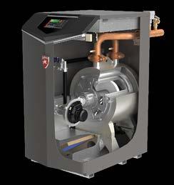
The iGEN Technology i2 unit is a self-powering gas-fueled (natural gas or propane) condensing heating appliance with around 95% optimal efficiency, using PVC or CPVC venting. It operates a Vapour Expansion Cycle to output heat and generate electric power using four main components (evaporator, expander, condenser and pump) and a refrigerant cycle:
• The evaporator takes heat from gas combustion and changes the refrigerant from liquid to vapour.
• In a scroll expander, decreasing the vapour pressure produces the electrical power.
• The condenser changes the refrigerant from vapour to liquid, emitting heat.
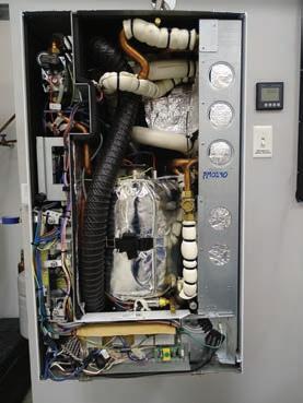
• The internal pump uses some electricity and drives refrigerant pressure in the loop. An inside view of the gas-fueled self-powered iGEN i2.
not only during the heating season, but year-round with the hot water supply.
While some other companies in the heating market are developing and marketing CHP products, they are primarily for larger commercial or light-industrial applications where the focus is more on the electrical output.
“We see this as an emerging market with only a few small players now, but we believe it will become more important,” says Lai. And as the company tries to broaden its reach, they know there are challenges ahead. “We understand it’s a premium product, and it’s going to be priced higher than even your most high-end boiler, because it’s doing more,” he says.
One of their challenges is educating the market on what they have. They’re working to educate home builders on the product, and they’ve co-authored a standard with UL because it is a whole new class of appliance.
Another potential challenge going forward is the long-term market shift towards electrification. Across the country, governments are promoting heat pump technologies and moving away from fuel-burning units. But this is where Lai
believes iGEN can help the market.
“We know for temperatures below -15C or so heat pumps require additional electric resistance heating, which drives up cost and decreases efficiency. Yes, we are a gas-burning appliance, but we can replace inefficient water heating and provide supplemental heat for a heat pump that can’t keep up on colder days.
“The people we’re speaking with, whether it’s the government, utilities or even other HVAC appliance manufacturers, we’re saying, ‘We’re a bridge technology, an enabling technology between where the industry is today and where it wants to get.”
He believes that as a small company, iGEN has a good sense of where the market is headed and what people want. “We just need the big boys to recognize that we’re on to something, and to see how we can help.”
In addition to its micro-CHP appliance, the company is also a Microsoft partner and is working to develop an HVAC IoT platform. They're working on cloud-based algorithms to optimize and bring advanced intelligence to many HVAC platforms. This Canadian company is working on solutions it believes will eventually elevate the entire HVAC industry into the high-tech field. <>
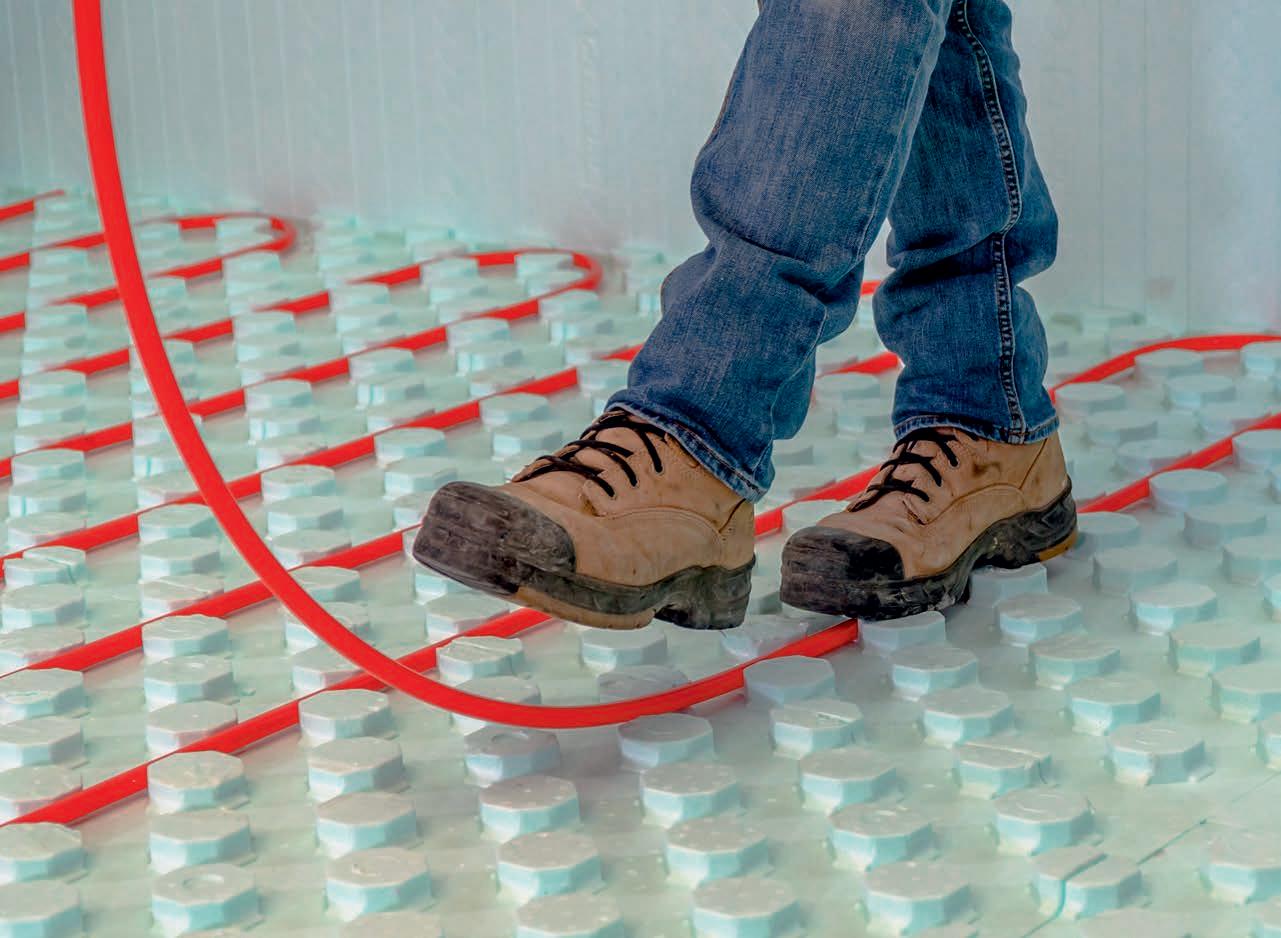
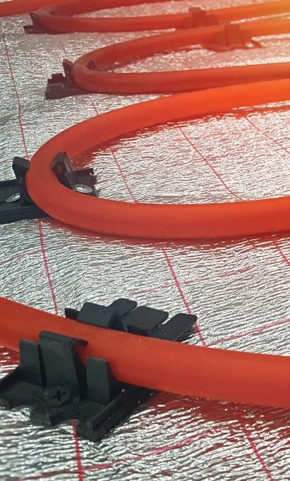
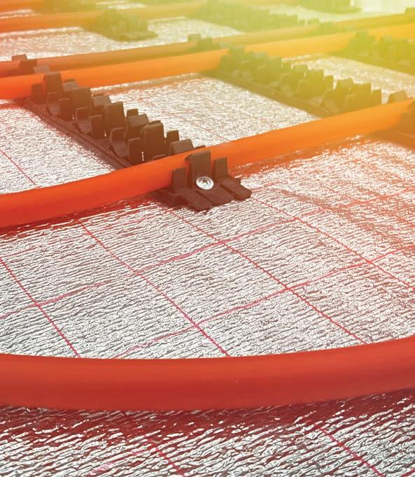
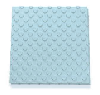
HYDROFOAM® IS THE IDEAL RADIANT FLOOR INSULATION PRODUCT FOR RESIDENTIAL AND COMMERCIAL CONSTRUCTION PROJECTS.
The floor of a building is often the most ignored surface when it comes to insulation. The floor, when insulated with HYDROFOAM, completes the building envelope and increases comfort and energy efficiency.
HYDROFOAM maximizes radiant floor heating by ensuring the heat is dispersed evenly throughout the entire floor area, providing building occupants with a comfortable living and working environment.

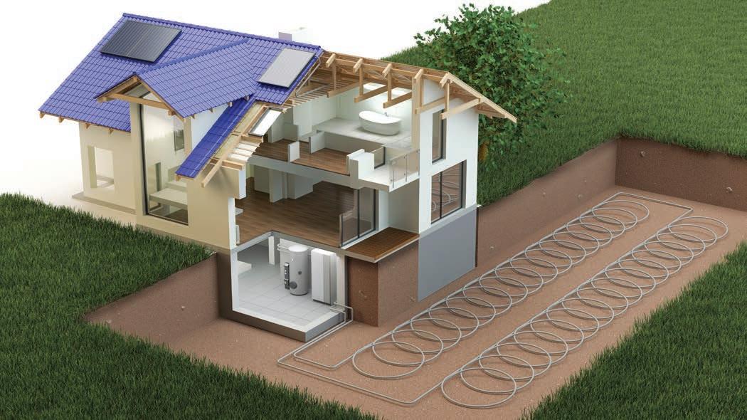
After years of experience, it’s time to share my thoughts on geothermal system design and how we can all create better solutions with more collaboration up front.
BY CURTIS BENNETT
When I told my wife that I was writing an article for this issue she asked what it was about. I said, “Over controlling.” Her and my daughter both laughed and said “That should be easy for you!”
I think they were talking about something else. Lol. I love controls. I eat and breathe controls. They’ve been my life for 20 years now. Controls are a subject that can be written about from at least two ways. The first would be how to keep projects simple and inexpensive, and the other extreme would be developing
building management systems (BMS) that are controlling every aspect of a complex system. Either way still takes skill and knowledge to achieve an end goal. That end goal is not to have controls installed on the wall; the end goal is a happy home or building owner.
There is something to be said about the simplicity of an aquastat—yes, there really is. They can be easily installed and just as easy to troubleshoot if something is going wrong. Today’s topic is not that “simple”. We are going to look at what has been done on the other end of the spectrum.
I have said many times before that I am no expert in controls, but I have been around them long enough to have seen some issues that may help out some people in the future. Many times, in the world of geothermal (otherwise known as ground source heat pumps) I have seen some “overkill” when it comes to controls. Sometimes simple is good,
and most of the time bigger is not better when it comes to these controls.
I have found over the years that geothermal systems tend to be the worst offenders when it comes to over complication. I do believe that the over control situation often comes from the fact that it is a geothermal system and there is a tendency to want to ‘wow’ the customer.
Now there is nothing wrong with doing that, I try to do it all the time, but sometimes it’s the controls that suffer. Geothermal by its nature is trying to gain efficiency in a system, so I think we tend to put a few more things in than might be needed. Once again, I never write to poke or prod anyone or pretend like I speak gospel. So just keep that in mind as you continue.
Over controlling is not done on purpose, at least not for the most part. I think it’s a gradual process that tends to come out of necessity in geothermal. Geothermal systems have more “parts” to them than a traditional boiler system. Another reason for the over controlling
“Geothermal by its nature is trying to gain efficiency in a system, so I think we tend to put a few more things in than might be needed.”
is the longing for every bit of efficiency—the big COP (coefficient of performance)—trying to squeeze every Btu out of the system with the least energy possible. I sometimes think that if the house being installed into had a few extra hamsters in it, some installers would try to hook them up to a wheel to get some extra heat.
The number one problem I see in over controlling comes from necessity, but not the good necessity. Too many times I have seen a full mechanical system designed, AND THEN the controls are designed in. This creates a huge problem. If you don’t design mechanical systems to be controlled with controls that are available then this is the start of the downhill slide.
Too many times we get this call: “Here is the mechanical system, what controls do we need?” Now don’t get me wrong, I do understand why it’s done this way, especially on big projects. Projects that are engineered are always done mechanical first and then controls are added after, and even with that the controls may need to be DDC or BMS.
The problem with adding controls after is that usually the controls cannot do everything that needs to be done in one control. So more controls are added, and then they have to communicate with each other, and that poses more problems. Relays get added to interlock and turn off pumps and heat pumps while other devices are running, and so on. This is what I mean by necessity.
The way the mechanical system was designed did not take into account how to control it properly. We tend to add more controls when the system seems to not be working correctly. When I think we should step back and try to see where the real problem lies.
Ok, tell me I’m not the only one out there that has seen a system where you know they just keep adding controls to fix issues because some things are not working, until you have this mess that is way too out of control (ironic, I know). The more complex a control design the harder it is to tie everything together.
The other more notorious version of over controlling “syn -
drome” is the one that comes when we try to do too much right from the start. Way too much. Like I said above, I understand that we want to make the most efficient systems—that’s why we keep evolving controls—but the issue is at what point do we start gaining very small amounts off efficiency at a higher cost. That desire for ultimate efficiency is why I think this happens in geothermal systems more than traditional boiler systems. I do caution at this point that the home owner is the one left with the system at the end of the day.
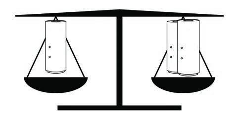
One of the biggest problems I see, well ok there are two. First is the infamous single tank for heat and cool water, when there should be two tanks. One for hot and one for cooling. We so often get calls to help out with a system that won’t work properly. Of course they blame the controls first (or maybe I just hear that more because that’s where my head is). After some quick deduction of the system and the needs of the installer you can see that they want heating and cooling at the same time, but that is not possible with a single tank. So then we start adding relays to interlock heating and cooling systems out of each other, and then add a winter and summer switch-over thermostat for the homeowner.
Continued on MH18


REGISTER TODAY for your chance to win one of 10, $50 gift certificates from Boston Pizza
There will be 5 winners awarded for each day of the Summit. Winners will be notified by HPAC on March 26th. Collect your digital gift card at the Amvic booth March 30-31.
Registration for the Summit is FREE from our friends at – what a deal!
These systems are installed to be efficient, but as soon as you heat up the tank to satisfy the heat load and then when that finishes it must cool the tank all the way down to satisfy the cooling load, and then vice versa all the time. Not good, not good at all.
The second big problem is when there is not enough field system. Either not enough holes drilled or not enough horizontal field system made. This presents some big issues with over heating or freezing the field system. Then we have to add more controls to alleviate this underlying issue. You also guessed it, these controls need to talk with all the other controls.
Now don’t get me wrong, I like controls, a lot, and I like to make sure systems run correctly, but I don’t like it when they have to add up because the mechanical system was not designed correctly. We definitely do our best to fix issues with controls, but sometimes we do end up over controlling things. And then we end up putting band aids on a compound fracture. It may stop the bleeding if we put enough on, but the arm is still broken underneath.
The final problem I see are people adding controls just to add controls. Most often the goal is efficiency, but the real loser is the homeowner. They become tied to the controls contractor, because the system is so complex anytime something is weird they need to call. Some of these over controlling items are extra set points for extra tanks, switchover thermostats for summer and winter, or just adding relays to interlock sys -
tems that don’t need it. It seems good at the time, but these additions become complex at the end of the day. Remember, the goal is to have a happy homeowner.
Designing geothermal systems with the controls in mind from the beginning is a good start. Controls are evolving with more capabilities to make the necessary adjustments needed to help systems to be more efficient, and these built-in extras it will make it easier for the installer as well as the homeowner. When homeowners are happy then contractors are happy. And that helps our industry. <>

Curtis Bennett C.E.T is product development manager with HBX Control Systems Inc. in Calgary. He formed HBX Control Systems with Tom Hermann in 2002. Its control systems are designed, engineered and manufactured in Canada to accommodate a range of hydronic heating and cooling needs commonly found in residential, commercial and industrial design applications.
Speakers include: Siegenthaler, Bean, Miller, Goldie, Bennett, MacNevin
Topics include:
- Air-to-Water Heat Pumps
- Reducing Water Temperature in Existing Hydronic Systems
- Energy Metering
- Selling Hydronics to Builders
- Buffer Tanks
- Snow and Ice Melt


The session-packed 2021 Modern Hydronics Summit will be held online using a virtual event platform that enables live text and video chat features.
BY HPAC STAFF
Since 2013 the team at HPAC Magazine has been hosting our one-day Modern Hydronics Summit every two years in the fall—with the event getting bigger and attracting larger crowds every time. With the worldwide pandemic placing all live industry events on the sidelines since the spring of 2020, this year our team has pushed the calendar forward and will be hosting the largest-ever Modern Hydronics Summit on March 30 and 31 as a virtual event.
Hosting the Summit online allows us to deliver more programming than our traditional one-day events, and also makes attendance accessible to a much greater audience of hydronic industry professionals from across the country.
Knowing how busy the industry is at this time of year, we have split the event into two half-days. Attendees will be able take in the educational sessions and also visit the online exhibit hall and network with colleagues.
Although nothing can replace the interactions at a live conference, our virtual event platform recreates some of the experiences, and instead of footsteps, clicks on the mouse will move you from place to place.
The Exhibit Hall offers attendees the opportunity to view and download literature from manufacturers and service providers, and networking features will allow attendees to strike up conversions, via email, live chat or even video
The 2021 Modern Hydronics Summit includes nine educational sessions from the largest cast of hydronic experts we’ve ever assembled.
TUESDAY, MARCH 30 (all times Eastern)
NOON – 12:50 PM: Reducing Water Temperature in Existing Hydronic Systems Part 1 (John Siegenthalter)
1: 20 – 2:00 PM (concurrent sessions):
Air-to-Water Heat Pumps (Mike Miller) Snow and Ice Melt Solutions (Lance MacNevin)
2:30 – 3:00 PM (concurrent sessions): Buffer Tanks (Steve Goldie) Selling Hydronics to Builders (Murray Pound)

WEDNESDAY, MARCH 31 Noon – 12:50 PM: Reducing Water Temperature in Existing Hydronic Systems Part 2 (John Siegenthalter)
1: 20 – 2:00 PM (concurrent sessions): Energy Metering (Curtis Bennett) Update on NRCan’s Energy Efficiency Policy (CHC)
2:30 – 3:15 PM: Siggy and The Bean: Things We’d Like to See (John Siegenthaler & Robert Bean)
3:15 – 3:30 Sweet Heat Award Presentation (John Siegenthaler & Robert Bean)
All of the sessions will be recorded and available to all registrants for on-demand viewing for two months following the event, so nothing will be missed. And courtesy of event sponsor Resideo, registration to the 2021 Modern Hydronics Summit is free.
chat with manufacturers and suppliers at the virtual booths.
A Networking section allows attendees to scroll through the list of attendees and start private chats at any time with colleagues, either texting or via video link. And a Group Chat section will enable like-minded hydronic pros to
drop in on chats with their colleagues. During the Sessions, while following along with the presentation, we encourage attendees to participate in the Public Session Chat that will appear on the right side of the screen. Instead of raising your hand to ask a question, just type it into the ongoing dialogue in the Chat.
“Hosting the Summit online allows us to deliver more programming than ever.”
Session speakers will be on-hand and able to address your questions and react to your comments on the spot.
The experience will be what you make of it. We encourage all registrants to visit the platform early and “walk” or click through the different features available.
Last Fall we launched the first ever Sweet Heat contest, inviting hydronic contractors across Canada to get their cameras out and share their creativity, artistry and resourcefulness in delivering “Sweet Heat” to their customers.
The response has been great, and the entries have been rolling in, but we’re looking for even more.
Entry is simple – send us photos (before and after shots) of an installation completed in Canada. Visit hpacmag.com to

TECA’s updated hydronic systems design software is integrated into the TECA Heat Loss & Heat Gain software to automatically start hydronic designs for: radiant floor design and layout; baseboard layout; fancoil CFMs; indirect water tank sizing; and pump sizing. The software is available for download. teca.ca
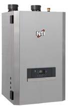
The FTVN series from NTI are high efficiency, wall hung boilers using a durable, vertical down-fired stainless heat exchanger. They also include 10:1 modulation and 96% AFU, an integrated ECM pump and DHW diverter, quick connect components, and WiFi connectivity for remote monitoring and alert notifications. ntiboilers.com
find the Sweet Heat Contest entry form and send it in. The entry deadline is March 12th. Submissions are limited to one per contractor, and it can be a new installation or a retrofit.
The winning entry, and two runners up, will be discussed and announced by John Siegenthaler and Robert Bean at the end of the Summit (March 31).
In addition to having the winning entry shared across our social media channels, the winner will be interviewed by HPAC’s editor and featured on the cover of the Fall 2021 edition of Modern Hydronics.
The 2021 Modern Hydronics Summit wouldn’t be possible without the support of sponsors and exhibitors. As of press time: registration sponsor – Resideo, is making the event FREE to register; lunch and coffee sponsors – Amvic and Roth; keynote speaker sponsor – Caleffi; session sponsors –Arctic Heat Pumps, Mitsubishi Electric Sales Canada, NTI, and Viessmann.<>
To register for the 2021 Modern Hydronics Summit visit: modernhydronicssummit.com , it's FREE.
When visiting the Modern Hydronics Summit online March 30 & 31, be sure to visit the Exhibit Hall for more details on these products and much, much, more.
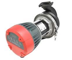
The Armstrong Compass R is an energy-efficient, variable speed, dry-rotor circulator available for heating and cooling, and potable water applications. It’s equipped with standard flange connections and large front-mounted wiring chamber and controls for easier and faster installation. armstrongfluidtechnology. com
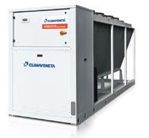
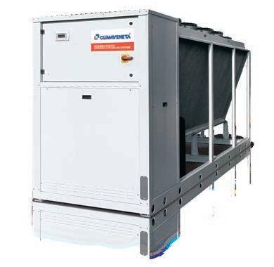
Climaveneta NX-N hydronic heat pump units are available in 14 different sizes from 45250 kW heating capacity, and are available with optional desuperheater for heat recovery function. Part of Mitsubishi Electric, the NX-N units can be used in combination with any hydronic equipment and can reduce a building's carbon footprint. climaveneta.ca
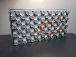
Amvic’s Ampex hydronic radiant panel combines rigid insulation, a vapor barrier and PEX tubing locking mechanism into a single solution that reduces installation time for both residential and commercial applications. The large, four-sided interlocking shiplap connector system makes for a quick, easy and secure installation of the panel, and the mushroom nub technology allows for easy walk-in pipe installation enabling increased job-site efficiency. amvicsystem.com
The next generation of the KNIGHT XL commercial boiler product family is here and available in five models, ranging from 399,000 to 1 million Btu/hr. The advanced units feature a 97% thermal efficiency, a 10:1 turndown ratio and extended venting up to 150 feet. Features also include a stainless-steel water tube heat exchanger and a 7-in. touch screen operating control.
aquatech-canada.com
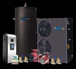
Arctic Heat Pumps are efficient monobloc low temperature air-to-water heat pumps capable of operating to -30C (-22F). Using enhanced vapor injection as well as DC inverter compressors and DC fan motors, the cold weather COPs are good for any hydronic heating system. The single system monobloc design means no refrigeration mechanical work is needed. Wi-Fi, with intelligent back-up are standard on all models. arcticheatpumps.com
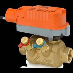
BELIMO’s PIQCV offers the advantages of a pressure independent control valve (PICV) in an ultra-compact size. The valve performs the function of a balancing valve and control valve. The pressure independent valve technology maximizes the energy savings of variable flow pumping systems while alsoaddressing unique control challenges for complex hydronic systems. belimo.ca
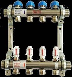
The Roth RSS Manifold, constructed of non-polished stainless steel, is available in 1-in. and 1-1/4-in. trunk sizes, with 2 to 12 loop connections. Sets include: straight isolation ball valves on trunk supply and return connections with temperature gauges; fill/drain/vent tees with ¾-in. garden hose thread, ¼-turn valve and manual (coin) vent; flowmeters on supply manifold outlets with 0 – 2 gpm scale; and flow regulator valves on return manifold outlets with manual multi-turn operators. roth-canada.com
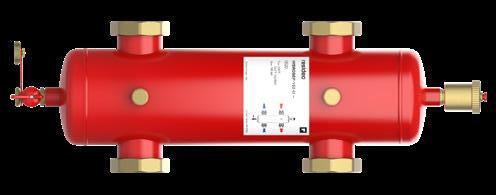
Adding the Resideo Hydraulic Separator to hydronic installs and retrofits, users can more easily balance source-side and load-side circulator flows, minimizing air turbulence while protecting components from backflow and debris. It’s a safeguard to help ensure a smooth-running system. Units come standard with insulation and magnet. Available in 1-in. to 2-in. union (NPT, sweat, press) and 2-in. to 6-in. flanged. www.resideo.com
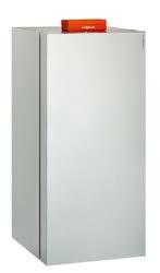
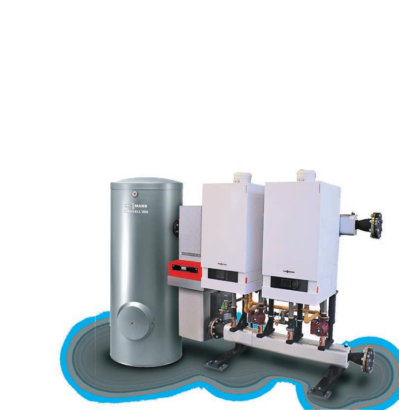
Viessmann’s Vitocrossal 300 is a compact, floor-standing, high mass, gas-condensing boiler, a solution for residential and light commercial applications – including high temp heating, cast-iron boiler replacements, and multizone systems. Rated input is 19 to 199 MBH (single)/1,592 MBH (cascade up to 8 boilers). There is no need for low-loss header, dedicated boiler pump, or primary/secondary piping, and it includes the Vitotronic 200 KW6B boiler & system controller. viessmann.ca
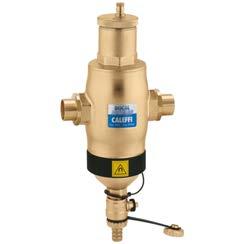
The Caleffi DIRTMAG magnetic dirt separator removes both ferrous and non-ferrous impurities continuously, featuring powerful removable magnets that remove up to 100% of the ferrous impurities, including magnetite, that can form in a hydronic system. The DIRTMAG has 2-½ times the removal performance of a standard dirt separator. caleffi.com
The SensorLinx Sensor System from HBX Control Systems is designed to measure and record the thermal energy used in a residential or commercial heating or cooling system for accurate Btu measurement—now with EN 1434 Certification. hbxcontrols.com
The AltSource highvolume electric boiler is a combination boiler-storage tank for residential use serving as a back-up energy source to the primary system in order to maximize output. Complete with its T2UltraSmart controller, the boiler provides improved comfort through precise temperature control. The AltSource comes with a limited 15-year warranty. thermo2000.com
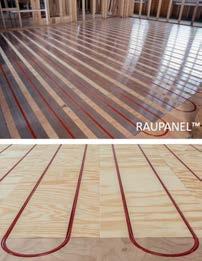
Used in residential and commercial projects, dry panel systems like REHAU RAUPANEL or RAUBOARD offer an easyto-install radiant heating option without pouring concrete or the need for structural reinforcements. The low thermal mass of the system components promote high heat conductivity, resulting in a fast response time to thermostat temperature changes. rehau.com
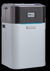
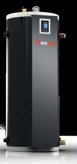
Weil-McLain Canada’s new ECO Tec high-efficiency condensing boiler for residential applications, delivers up to 95% efficiency in seven sizes. Available in both heating and combi versions, it can
provide space heating and up to 5.4 GPM of domestic hot water at a 70F rise. Features include a durable stainless steel fire tube heat exchanger, four thermostat inputs, built-in ECM circulator, and it can power and control up to five circulators. weil-mclain.ca
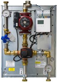
HeatLink's pre-fabricated commercial 4-way mixing panels include the components necessary to control a building’s radiant heating system supply water temperature. The panels may be used with a dedicated heat source or a nondedicated heat source with a heat exchanger. All panels include a 4-way mixing valve and motor, pump, circuit setter, thermometers, isolation valves, and cover.
www.heatlink.com

During a pandemic, in a cold-weather climate like Canada, the ability to separate thermal comfort systems from indoor air quality provides an inherent advantage.
BY ROBERT BEAN
Severe acute respiratory syndrome coronavirus 2 (SARSCov2) is the virus responsible for starting the 2019 pandemic that continues today with no foreseeable end in sight. The virus does NOT travel independently; instead, it is a respiratory particle guest originating from the respiratory pathways’ infected areas within infected individuals. The number of particles with the virus depends on the infection location(s) (nose, throat, bronchial tubes, and alveoli) and exhalation intensity (breathing, talking, coughing, sneezing, singing, shouting). This is important for general understanding, but it has little bearing on building design and operation and HVAC systems.
As we know, COVID-19 is a disease caused by the virus resulting in shortand long-term illnesses and death.
Despite the emphasis on personal and building hygiene, there remains little evidence that the virus’s spread frequently occurs from touching surfaces (fomite). That is not to suggest that one should not maintain good hygiene.
Close range inhalation of droplets and aerosols and inhalation of airborne par-

The American Society of Heating, Refrigerating and Air-Conditioning Engineers (ASHRAE) has dedicated pages on its website with guides, technical resources and recommendations for addressing COVID-19 concerns in the built environment: www.ashrae.org/technical-resources/ resources.
ticulates of some distance beyond the infected person(s) are the dominant transmission paths. The airborne vectors carrying the host particles with a virus is not magic; it is standard particle dispersion theory 101—that is…where the air goes – so goes the virus.
Suppose one person’s infected exhalation can become another person’s inhalation. In that case, there is a high probability of transmission if no protective measures are taken. That is why distancing and a proper mask appropriately worn indoors and, in some cases, outdoors is essential. These are two tactics in the overall strategy to reduce transmission.
Members of the international Indoor Environmental Quality General Alliance (IEQ-GA.net), including member organizations such as ASHRAE, believe there
is sufficient evidence to suggest that airborne transmission cannot be ignored. David B. Resnik noted in discussing the Precautionary Principle and Medical Decision Making, “One should take reasonable measures to avoid threats that are serious and plausible.”
ASHRAE’s most current position is “ventilation and filtration provided by heating, ventilating, and air-conditioning systems can reduce the airborne concentration of SARS-CoV-2 and thus the risk of transmission through the air. Unconditioned spaces can cause thermal stress to people that may be directly life-threatening and that may also lower resistance to infection. In general, disabling of heating, ventilating, and airconditioning systems is not a recommended measure to reduce the transmission of the virus.”
As I have said, “If satisfying a thermostat setting destroys the process of decontamination, deodorization and
dehumidification of ventilation air, the HVAC system is dysfunctional.”
How many HVAC systems do you know where ventilation and filtration are disabled when the thermostat has been satisfied? Think about that for a second, given the current situation. This is one of the significant benefits of hydronic systems; they enable the separation between indoor air quality systems and thermal comfort systems.
These systems are symbiotic under the umbrella of indoor environmental quality (IEQ) but independently serve the occupants without reducing effectiveness. When trying to manage an airborne pathogen’s transmission, we do not want to allow it to hang around. It is imperative to keep the ventilation and filtration systems operating ALL the time…and that lends itself perfectly to
hydronic-based systems.
My advice to readers; there is no safe definitive social distance nor exposure time. SARS-CoV2 does not come with a timer or an onboard navigational system; wherever the air goes, so goes the virus…it doesn’t know one metre from two metres from 10 metres. It doesn’t know what 10 seconds is, nor 30 seconds nor 15 minutes.
Wear proper masks properly in the presence of any uncertain risk. Personal and building hygiene is good but not a surrogate for air hygiene, resulting from appropriate ventilation and filtration. Vaccines are essential, but they are not the long-term solution to preventing transmission inside buildings. Counting on vaccines is a game of whack-a-mole. Preparing buildings and people for pandemics is a forever solution. <>
Public service announcement: if you must create an isolation room in your home, condo or apartment, see this link: www.healthyheating.com/2021.COVID. Residential.Isolation.Rooms/2021. Residential.Isolation.Room.htm
Resnik. 2004. The Precautionary Principle and Medical Decision Making. Journal of Medicine and Philosophy, 29(3):281-299.

Robert Bean is director of www.healthyheating.com, and founder of Indoor Climate Consultants Inc. He is a retired engineering technology professional (ASET and APEGA) who specialized in the design of indoor environments and high performance building systems. Some
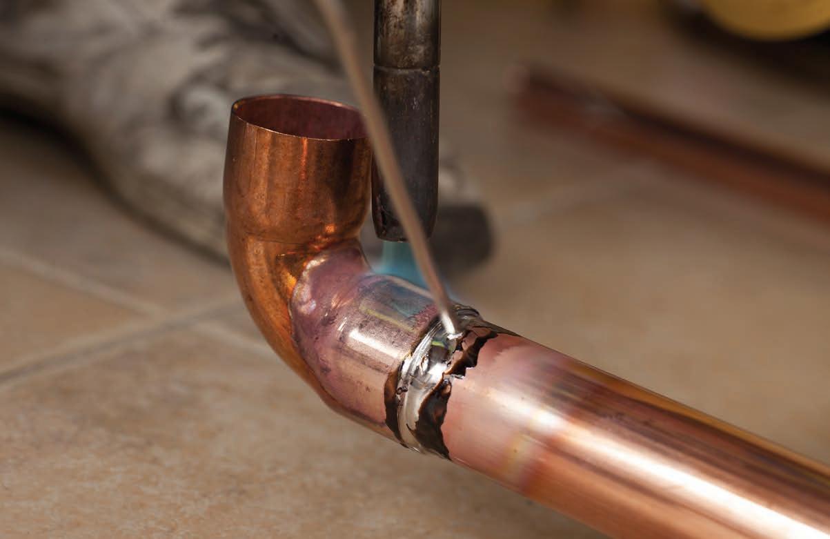
The introduction of flexlible tubing materials and new press fittings is revolutionizing the hydronics industry in many positive ways.
BY JOHN SIEGENTHALER
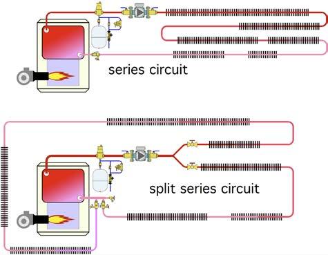
Few would argue that fin-tube baseboard was the “flagship” heat emitter in North American hydronic heating systems through much of the 20th century. It’s origins go back to the 1930s where it represented a radical departure from the status quo of cast-iron radiators. Since then fin-tube baseboards have maintained their place in residential hydronic systems, despite the fact that its fundamental construction hasn’t changed much.
A typical residential fin-tube baseboard system connected multiple baseboards into either series or “split series” circuits as shown in figure 1 .
In many systems the fin-tube elements in the baseboards used ¾-in. copper tubing. Baseboard elements were connected by soldering lots of copper elbows to short “stubs” of copper tubing. These piping assemblies routed flow down through the floor deck and offset it horizontally to account for
wider foundation walls relative to the typical 2x4 studs used in many 20th century homes.
It was common to use eight 90-degree soldered copper elbows to connect each baseboard in such systems. Much of that soldering had to take place in the cramped spaces between floor joists, and above foundation walls. The joints were often made in close proximity to wood, as evidenced by plenty of “char scars,” which to me scream of unprofessional workman-
Continued on MH28

THE BRUTE FT® BOILER & POWERSTOR SERIES® INDIRECT WATER HEATER.
Together, they deliver the perfect heat and hot water solution for your customers.
• True Power. The Brute FT® can easily handle the space heating needs of today’s modern homes – even on the coldest winter nights.
• Exceptional Efficiency. The Brute FT®’s modulating technology automatically adjusts fuel usage to match heat demand – to save up to 20%! ENERGY STAR® rated, 95% AFUE.
• Outstanding Hot Water Performance with Fast First Hour Delivery. The PowerStor Series® provides one of the lowest pressure drops and highest hot water outputs of any indirect fired water heater in the industry. Available in single wall, double wall and stainless steel. All Bradford White products, are built For The Pro® for easy installation and top performance and reliabilty. Backed by our unmatched 24/7 technical support. Learn more at bradfordwhite.com

ship. Lots of time was required to measure, cut, ream, clean, flux, solder and wipe all those joints.
Once these series or split-series systems were put in operation there wasn’t much that could be done to adjust heat output on a room-by-room basis. It was not uncommon to hear complaints that the heat output in the room at the end of a series baseboard circuit was a bit “light.”
This was usually caused by sizing the baseboards based on the average water temperature in the circuit, rather than the actual inlet temperature at each baseboard.
“It was not uncommon to hear that the heat output at the end of a series baseboard circuit was a bit 'light'.”
There weren’t many choices for materials when fin-tube baseboard was the standard for residential hydronic heating. Most installers just soldered ¾-in. copper tubing, elbows and baseboard elements together to form series circuits.
Some used diverter tees to allow some of the baseboards to be bypassed. The latter technique could be used to limit heat output of each baseboard— provided some type of valve was installed in each branch piping path.
However, because a single circulator provided flow to all baseboards, this approach still didn’t allow each baseboard to independently call for heat. It also suffered from the same sequential temperature drop characteristic associated with any circuit with series-connected heat emitters.
Parallel piping methods such as “two-

Thermostatic radiator valves
baseboard #6
baseboard #5
baseboard #4
baseboard #3
baseboard #2
Baseboard #1
Variable-speed pressure- regulated circulator 1/2" PEX or PEX-AL-PEX tubing
manifold station
pipe” reverse return, were understood by mechanical system engineers, and often used on commercial fin-tube applications, but seldom applied in residential systems.
The arrival of PEX tubing in North America in the early 1980’s did not immediately affect how the fin-tube baseboard was installed. Instead, when first introduced to North America PEX was viewed with a degree of skepticism by
many heating pros who had spent years working with rigid metal pipe.
Today, most heating pros view PEX, or similar tubing such as PEX-AL-PEX or PE-RT as a “universal” hydronic tubing. They have confidence that it can work in a wide variety of systems including many types of radiant panels as well as with panel radiators, fan-coils and even fin-tube baseboard.
Continued on MH30
PEX tubing makes it possible to connect fin-tube baseboards in parallel rather than series. Figure 2 (previous page) shows this concept as a “homerun” distribution system.
Each baseboard has two ½-in. PEX tubes routed to it from a central manifold station. That tubing can be easily pulled through holes in floor framing or up through studded walls. In most cases it’s possible to install this tubing without any joints between the manifold station and the baseboard. The parallel piping circuits provide several benefits not possible with series piping.
First, each baseboard receives essentially the same supply water temperature. The sequential temperature drop associated with series piping or diverter tee systems is eliminated. This makes it easier to size the baseboards to their respective room heating loads.
Second, it’s possible to regulate flow rate through each parallel circuit. This can be done using valves built into the manifold station, or with valves at each baseboard.
Third, even though it’s possible to operate all parallel circuits as a single zone, it’s very easy to go one step further and set up each baseboard as an independently-controlled zone.
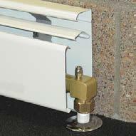
Flow through each baseboard can be controlled using “wireless” thermostatic radiator valves mounted at the inlet of each baseboard, as shown in figure 2. No wires, no batteries, no programming, just simple, reliable and accurate room comfort control.
Another option is to mount the radiator valve and actuator head inside the baseboard enclosure, or under the floor, and use a remote setting dial connected to the valve’s actuator head by a capillary tube. This is nice in situations where occupants don’t want to bend over to adjust the room comfort setting.
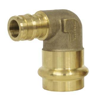
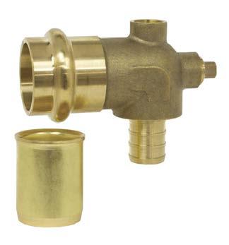
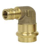
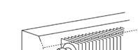
It’s now possible to connect PEX tubing to the copper tubing in a baseboard element without soldering the latter. Figures 3a and 3b show two fittings designed for this purpose.
The elbow in figure 3a transitions from an ASTM F1960 “cold expansion” connection for ½-in. PEX tubing, to a press connection on ¾-in. copper tubing.
The fitting in figure 3b transitions from an ASTM F1807 crimp connection for ½-in. PEX tubing to a press connection on ¾-in. copper. This fitting also has two 1 8 -in. FPT tappings, one of which can be used for an air vent. The other is simply plugged.
The brass sleeve shown in figure 3b is a tube stiffener that allows a press connection on the thin wall copper tubing used in modern fin-tube baseboard. Both of these fittings are ideal for “flameless” connections to fin-tube baseboard.
No more char marks or messing around with multiple copper elbows and short tube stubs in those tight confines between floor joists.
If electrical thermostats are preferred just mount 24VAC valve actuators on the manifold station and connect them to the thermostats using a multi-zone relay center.
When the system is zoned use a variable-speed pressure-regulated circulator. Set it for constant differential pressure operation. As the thermostatic radiator valves or manifold valve actuators open and close the circulator automatically ramps its speed up and down to keep the flow rate in each parallel branch nearly constant.
This type of circulator also eliminates the need for a differential pressure bypass valve, and significantly reduces electrical power consumption relative to fixed speed circulators.
From a single zone series circuit constructed using 100-plus solder joints, to multi-zone systems using zero soldered joints and low-power variable speed circulators. The methods and materials available for installing fin-tube baseboard have come a long way in the last few years. Are you taking full advantage of them? <>
John Siegenthaler, P.E., is a mechanical engineering graduate of Rensselaer Polytechnic Institute and a licensed professional engineer. He has more than 40 years experience in designing modern hydronic heating systems. Siegenthaler’s latest book is Heating with Renewable Energy (see www.hydronicpros.com for more information).
Low carbon, high performance, no compromise.
From light commercial applications to large multi-unit centralized plants, Climaveneta has a low carbon solution to help you realize your masterpiece, without compromise. So, whether you require a hydronic heating or cooling solution for a retrofit, a new construction project, or an industrial application, with Climaveneta you can bring your vision to life exactly as you imagine it.
• Climaveneta’s 50 years of experience meets Mitsubishi Electric’s nearly 100 years of innovation
• High-efficiency heat pumps that optimize heating performance for the Canadian climate
• Reliable heating and cooling solutions to maximize occupant comfort and minimize operational costs
• Flexible and customizable options to suit your individual project needs
Learn more at:
Climaveneta.ca