Suggestions for five technologies/products that could help move the hydronics industry forward.
BY JOHN SIEGENTHALER
Product innovation has moved the North American hydronic industry a long way over the last 50 years. In the 1970s, a typical residential hydronic system used a fossil fuel boiler to supply two or three zones of baseboard with scalding hot water. Today, some systems use geothermal or air source heat pumps, possibly supplied by renewably-generated electricity, to supply room-by-room comfort using bathtub temperature water circulating through radiant panels.
Continuous improvement is essential to maintaining a healthy industry, especially if that industry expects to gain market share against competing technologies. To promote future growth, new products and installation methods should (in no particular order):
• make systems easier and faster to install.
• deliver equal or better comfort than their predecessors.
• demonstrate increased efficiency.
• improve system reliability and reduce maintenance.
• correct deficiencies in existing products or installation methods.
With these objectives in mind, the following are my thoughts on five products I think could further enhance North American hydronics technology.
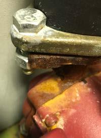
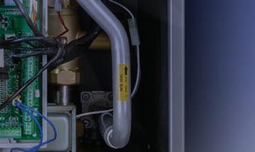
1A vapor-tight insulation system for circulator volutes
If you’ve used cast-iron circulators in any type of chilled water cooling system,
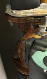
or in earth loops for geothermal heat pumps, you’ve likely seen what happens to the volute, steel flange bolts and even steel handles on isolation flange valves when they rack up a few operating hours well below the dewpoint temperature of the surrounding air. All these components quickly develop surface oxidation. (figure 1 shows an example.)
Over time the orange condensate drips onto anything below it. This “superficial” rust doesn’t compromise the circulators performance, but it does make a mess.
The obvious solution is to add a vapour-tight insulation envelope around all parts of the circulator other than the motor can and wiring compartment.
Some manufactures offer molded foam clam shells that fit specific circulators— usually commercial-sized ECM products. These can limit condensation if they are properly sealed at all locations where air could contact any chilled metal surface.
Wouldn’t it be nice to have an insulation/vapour barrier system that could fit any circulator that may have to operate at sub-dewpoint temperatures?
Perhaps a block of solid insulation
material that could be easily molded, on site, to the shape of the installed circulator, and then attached as two mating parts. Maybe a hollow plastic shell that could be fit around the installed circulator volute and flange joints and then filled with expanding foam.
An elastomeric gasket would be part of either approach to provide the air-tight seal with the circulator’s motor can. The portion of the circulator that contacts the insulation could be sprayed with a “release agent” that prevents strong bonding in case the insulation had to be removed to service or replace the circulator.
2A Simple, inexpensive temperature controller for variable speed ECM circulators
Over the last 25+ years I’ve designed many hydronic systems that had one or more circulators with standard PSC motors operated by variable speed controllers. The controllers used a combination of AC wave chopping and frequency control to vary the speed of the circulator.
However, the circulator world is changing. Those familiar wet-rotor circulators with PSC motors are about to go the way of 100 watt incandescent light bulbs. I suspect they will be out of production within the next five years. Circulators with higher efficiency ECM motors are quickly becoming the new normal.
Variable speed controllers using wave chopping and frequency control cannot be used with ECM circulators, so it’s just a matter of time until those controllers follow PSC circulators into the annals of hydronic history.
The good news is that many of the new ECM circulators can be speed-controlled using a 0-10 VDC input signal (not to be confused with the standard
Figure 1
up to 3 temperature sensors controller
0-10 VDC control signal
120 VAC electrical power supply). A typical scenario is for the circulator to remain off until the control signal reaches 2 volts. The circulator’s speed increases in direct proportion to the control voltage, reaching full speed at 10 volts.
What’s needed are simple and inexpensive controllers that generate a 0-10 VDC output signal in relationship to some temperature-based condition. The latter could be a user-set “target” temperature, with circulator speed selectable as increasing or decreasing as the temperature measured by the controller varies from the target value. This function allows for supply water temperature control as well as boiler anti-condensation protection.
The controller should also handle differential temperature control, such as used in solar thermal systems or biomass boiler systems. It should also be able to provide variable speed injection mixing based on either a fixed target supply temperature or a target temperature calculated using outdoor reset logic. All these functions are just selectable code within the controller’s firmware. The controller should have connections for up to three temperature sensors, as shown in figure 2
3 A multi-function controller for biomass boiler systems
There are lots of applications for boilers burning wood pellets or chips. These “biomass” boiler systems require several control functions including boiler anti-condensation protection, boiler firing based on two or more temperatures within a thermal storage tank, variable speed injection of heat into a distribution system, differential temperature control to prevent auxiliary heat from entering storage, coordinated operation of an auxiliary boiler and zoning.
All of these functions can currently be provided by combining several independent single-function controllers along with an assortment of relays.
Although these “multi-box” control systems work, their installation and programming can be challenging. I can attest that this has been a significant barrier to successful biomass boiler installations, especially in residential or light commercial applications.
This situation could be greatly improved if the market provided an integrated controller to handle all necessary control functions for these systems. The functionality exists, it’s just a matter of repackaging it in one box.
4
Indirect tanks with larger coil heat exchangers
The future of hydronics is low water temperature. Contemporary heat sources such as geothermal water-to-water heat pumps or air-to-water heat pumps typically max out at water temperatures in the range of 120-130F. That’s hot enough for many types of heat emitters, such as well designed radiant panels or panel radiators. It’s also sufficient to create domestic hot water at perhaps 110 to 115F—if there’s a suitable heat exchanger between the source water from the heat pump and the domestic water.
Most of the currently available indirect water heaters in North America are very limited in such applications. The internal coil heat exchangers in these tanks don’t have sufficient surface area to transfer heat from a much lower temperature heat source to the domestic water at the heat output rate of the source and at a minimum temperature differential of only 5 to 10F. The result will be short-cycling, heat pumps locking out on fault conditions and complaints about inadequate domestic hot water.
Most North American indirect water heaters were developed assuming a boiler would be the heat source, supply-
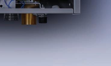
Figure 2
internal stainless steel or copper coil heat exchanger
Figure 3
ing water to the coil heat exchangers at temperatures of 180-200F. Swap in a heat pump and you have a very significant heat transfer “bottleneck.”
One solution is to use an external stainless steel heat exchanger sized for very low approach temperature differences. This works, but it’s arguably more complex than an indirect water heater.
Another solution would be to increase the surface area of the coil heat exchanger inside indirect tanks. Coils with three to five times the surface area of a typical indirect are needed. Such coils would likely span from the bottom to the top of the tank as depicted in figure 3.
The coils could be made of either stainless steel or copper. The water passing through them could be from the heat source, or it could be domestic water. The later “reverse-indirect” concept allows the tank to provide domestic wa -
ter as well as buffering for zoned space heating loads. It also allows the pressure vessel to be made of carbon steel, which is more affordable than stainless.
I would also suggest that such tanks have R-24 F•hr•ft 2/Btu insulation on all surfaces and ample ports for a variety of applications. Think of such tanks as high quality “Thermos bottles,” capable of storing heat for several hours, or perhaps a couple of days with minimal temperature drop.
5
Peel & stick elastomeric foam pipe insulation that sticks
My last plea is born out of frustration. I’ve had many occasions to see (and fix) peel & stick elastomeric foam pipe insulation with seams that have reopened only a few weeks after installation. I suspect that I’m not the only one who has experienced this problem.
I’ve fixed it using 1.5-in.-wide highquality vinyl electrical tape centered along the slit line. This works, but it shouldn’t be necessary. Perhaps the product branding should change from “peel & stick” to “peel, stick and stay.” Perhaps some of these ideas will come to fruition to advance the North American hydronic market. <>
John Siegenthaler, P.E., is a mechanical engineering graduate of Rensselaer Polytechnic Institute and a licensed professional engineer. He has more than 35 years experience in designing modern hydronic heating systems. Siegenthaler’s latest book is Heating with Renewable Energy (see www.hydronicpros.com for more information).
Representing Lochinvar branded residential and commercial hot water and heating boilers, Aqua-Tech Sales and Marketing Inc. provides top of the line branded solutions and support services to its clients across Canada. Our people bring experience, skills and commitment to supporting our distributors and installers to help them grow their businesses.
From many different product solutions to help you meet your customers’ needs, to technical engineering support, design and bid assistance, extended hours technical support, customer and market insights, well stocked inventory, training, support programs and so much more.
OUTDOOR RESET
The underutilized king of hydronic controls
BY ROBERT WATERS
Outdoor reset control technology for hydronic heating systems has been around for decades. I learned about the technology when I started working for CanaPex (predecessor of Uponor) in the late 80’s. I was designing hydronic radiant floor heating systems and was taught to recommend a Tekmar four-way mixing valve with motorized actuator and outdoor reset control for every system.
Later, when I moved to Viessmann in the mid 90’s, I learned about the Trimatik-MC, the Viessmann boiler control system that combines separate outdoor reset controls for both the boiler and the system via motorized mixing valve. Both of these European-based controls were examples of the rapidly growing market for digital outdoor reset control technology.
Outdoor reset control has been mandated for both new and existing boilers in many European countries since the 1990’s. The digital control market certainly has changed and grown significantly since those early days of my
career, but the benefits that outdoor reset technology provides are still very much the same; namely reduced energy use and cost while improving occupant comfort.
You would certainly expect a very mature and established technology like this, with such great benefits, to be widely used for all hydronic heating systems. However, based on my discussions with several industry veterans about the current usage rate of outdoor reset controls, this is not the case.
I was told that outdoor reset controls are still only being used sporadically on residential hot water boiler installations. They are more common in commercial applications where engineers and owners have recognized the significant energy, cost savings and comfort level increases that can be achieved.
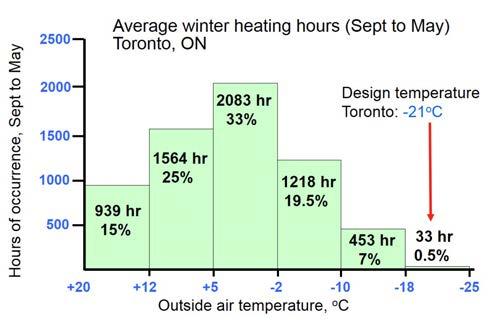
This control technology is especially important and timely with new pending NRCan efficiency regulations. As most may already know, NRCan Amendment 15 regulations that just passed into law last year will require all residential boilers <300 MBH to have an annualized fuel utilization efficiency (AFUE) ≥ 90% in 2023 (this means only condensing appliances). This regulation will also require that all residential boilers be equipped with an automatic water temperature adjustment device and must not be able to operate without the device.
Outdoor temperature reset controls, also referred to as weather responsive controls, work for both non-condensing and condensing boilers. They can also be used with heat pumps or biomass hydronic systems by controlling the temperature in the buffer storage tank.
As mentioned, outdoor reset controls provide two great benefits: 1) a dramatic reduction in energy use and cost, and 2) an increase in occupant comfort.
ENERGY SAVINGS
The energy savings result from the fact that the efficiency of any hydronic heat source is always higher when operating at a lower water temperature. This is due to lower stack temperatures, lower standby heat loss, and with condensing boilers, higher amounts of flue gas condensation. Another efficiency factor that also comes into play is that a boiler will be less likely to short cycle on and off in warmer times of the heating season when it is controlled with outdoor reset.
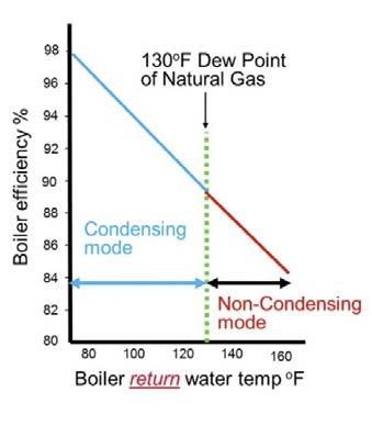
For any gas-fired condensing boiler the operating efficiency will vary in the range of 85% to 98% depending on the water temperature it is operated at (see figure 1).
Many are not aware of this efficiency range because they only look at the AFUE efficiency rating of the boiler. While a condensing boiler may have an AFUE rating of 95%, this rating was established in a test lab with a constant
140F supply temperature. If the boiler is operated in the real world, with a constant high temperature set point of 180F all heating season, it will very rarely condense and likely only have an efficiency in the 85% range.
However, if an outdoor reset control is used the supply water temperature is modulated all winter increasing the efficiency of the appliance in the shoulder seasons providing typical energy savings of 5 to 30%. They are also likely to extend the boiler lifespan by minimizing short cycling.
ENHANCED COMFORT
On the other hand, outdoor reset controls provide great energy savings while at the same time providing a more comfortable living environment for the building occupants. This is primarily achieved by eliminating the dramatic temperature swings that inevitably occur in any home whose heating boiler is operated at the same water temperature all year long. In order to provide consistent and even indoor temperatures, the heat supplied to the building must equal the heat loss from the building. The biggest factor affecting how much heat a building requires is the
outdoor temperature.
Even in a well-insulated building heat loss increases as the outdoor temperature falls. A hydronic heat source must be set to the highest water temperature setting that will satisfy the coldest day of the winter (design conditions). Design conditions however occur for a very small number of hours per year (less than 5% of the entire heating season: see ASHRAE data, following page), so for the vast majority of the heating season the heat source will be operated at a much higher temperature than is required to meet the load. So what happens when the outdoor temperature is warmer in the fall and spring? At these times the system inevitably overheats the building, creating temperature swings and poor control for the occupants. Overheating will be especially noticeable in high mass hydronic systems such as those with cast-iron radiators and radiant floor systems. In commercial or apartment buildings, where occupants do not directly pay for heating bills, energy use and costs increase even more as occupants open windows to compensate for overheating conditions. By continuously adjusting the system supply water temperature with an outdoor reset control the hydronic system is able to more closely match the exact heating requirements of the building at all times. The results are more consistent, comfortable space temperatures throughout the entire heating season. An added benefit in homes with fin-tube baseboard systems is a minimization of ticking expansion noises in baseboards by preventing large temperature swings.
HOW IT WORKS
Outdoor reset works by utilizing an outdoor temperature sensor mounted on the building’s exterior, ideally on the north wall and located away from anything that can give it a false reading such as a dryer or ventilation exhaust vent.
This electronic ambient air sensor actively monitors the outdoor tempera -
ture, and based on its reading a microprocessor calculates the heating demand and adjusts the output water temperature of the boiler accordingly. This results in the boiler only running as hot as necessary to achieve the desired indoor temperature.
There are two major categories of outdoor reset control; one being direct boiler reset control and the other being mixing reset control. Some controls will incorporate both boiler reset and mixing reset into one package. A mixing reset control utilizes either a motorized mixing valve or an injection pump to provide a mixed supply water temperature to an individual heating circuit.
Hybrid hydronic systems that have radiant floor heating (RFH) and fan-coil heating are the most common type of system that requires multiple supply water temperatures. For these systems the boiler reset control will provide a higher temperature to the fan coil circuit, and the mixing reset circuit provides a lower temperature to the RFH circuit.
There are many manufacturers today that provide both boiler and system outdoor reset controls. Most controls combine many other features and control capability such as multiple boiler control, wireless outdoor sensors, Wi-Fi connectability, and room temperature feedback. Many condensing boiler manufacturers now integrate the outdoor reset control directly into the boiler so there is no extra added cost.
SET UP
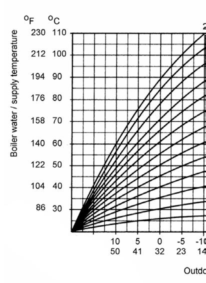
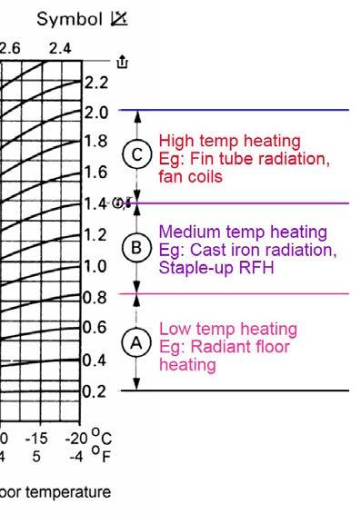
Outdoor reset controls must be set up and calibrated at the time of installation to meet the jobsite specific system requirements. The primary adjustment for any outdoor reset control is the heating curve setting. This setting determines what the maximum supply water temperature will be on the coldest day, and what the lowest supply temperature will be on the warmest day.
Continued on MH12
Figure 2
SOURCE: VIESSMANN/SOLAR WATER SERVICES
The heating curve is determined primarily by the type of heat emitter used in the system (see figure 2 above).
The control may come with a factory defaulted heating curve, but this will not meet the requirements of all types of systems. Different heat emitters such as high mass radiant floor, cast-iron radiator, and fin-tube will all require unique settings. When using a non-condensing boiler the minimum supply temperature must be set high enough to avoid flue gas condensation in the boiler and chimney (usually a minimum supply temperature of about 140-150F).
Other adjustments such as parallel shift, warm weather shut down (WWSD), and desired indoor temperature may also need to be adjusted. I do not have space in this article to get into the fine details of setting up an outdoor reset control, but there are many sources for those who want more information. Most manufacturers and distributors of hydronic equipment offer training and advice on how to do this properly, so reach out if you need help.
All of these adjustments must be done by the installing contractor at the jobsite, and I believe the lack of understanding of these settings is one of the primary reasons why some shy away from using outdoor reset controls.
UNDERUSED
In commercial hydronic systems outdoor reset control technology is being used extensively because it makes sense financially. Designers and building owners are seeing that savings can be substantial providing great ROI’s to the owner.
This same acceptance and use level has not spilled over into the residential hydronic market. Many hydronic installers still don’t use outdoor reset controls, even when the control is integrated into the boiler. Many don’t activate the outdoor reset control or bother to install the outdoor temperature sensor and wiring. They prefer to just set the boiler at one temperature and enable and disable it with a room thermostat through the TT connection.
Scott Boutilier, technical advisor/instructor with Viessmann-BC told me, “For many contractors, if they can get away without
using the outdoor reset control they will. Contractors just want to get in and out of jobs quickly, and they don’t want the hassle of running the sensor wire and setting up the control. Even with our boilers that have factory installed outdoor reset controls, many contractors don’t bother to install the outside sensor and just run the boiler at one temperature.”
Like many areas of the HVAC market, margins are always tight and very competitive, and many contractors want to make projects fast and easy. Many don’t want to ever have to return to the job after they are finished the installation. This usually results in a single thermostat, constant temperature boiler, and NO outdoor reset control. For many projects this means that the full potential of a new condensing boiler is not being optimized, and the customer is left with higher fuel bills and sub-optimal comfort levels.
It’s not all doom and gloom though, as everyone I spoke to say the true “wet-heads” are the exception to this trend and have definitely adopted the use of outdoor reset controls. According to Boutilier, “Good hydronic guys have taken the time to learn about outdoor reset technology, understand how it works, and they know how to adjust and fine tune the controls. They know how to make the controls work, can explain the benefits to their customers and they can easily sell the extra cost required to set up and configure the control.”
Unfortunately these hydronic contractors are not the majority. To those who are using them already, keep it up. These simple controls increase appliance efficiency, reduce greenhouse gas emissions, while at the same time make buildings more comfortable. This potent combination seems like a no-brainer to me!
It is time for everyone in the hydronic heating industry to step up and fully utilize this powerful, yet inexpensive, technology. This not only includes hydronic installers, but also regulators who inspect and enforce code and standards. No hydronic space heating system should be installed without one. <>
Robert Waters is president of Solar Water Services Inc. which provides training, education and support services to the hydronic industry. He has over 30 years experience in hydronic and solar water heating. He can be reached at solwatservices@gmail.com. <>
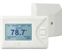
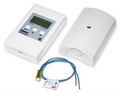
Sample outdoor reset controls and sensors.
UNDERSTANDING AIR TO WATER HEAT PUMP SYSTEMS: PART 1
The rise of electrification in residential HVAC will lead to greater adoption of heat pump technologies.
BY MIKE MILLER
As we all said goodbye to last year on December 31, for the HVAC industry this isn’t just the beginning of a new year, a new decade or an opportunity to set new personal and professional resolutions, 2020 and the years to follow will also represent further changes in our marketplace. And although we saw things change in the last decade, the one to come will be even more dramatic — of that I am sure.
The global conversations about a ‘greener’ world—electrification, carbon neutral or net zero buildings—is really starting to resonate across our continent and some geographic regions are already adopting rules and regulations that will prevent or make difficult to use fossil fuel fired equipment moving forward. These changes will, as has already been the
case in Europe, shift the landscape of heat sources away from fossil fuels as the primary energy provider.
Did you know that 2017 was the first time that heat pumps outsold the number of boilers as heat generators in Germany, and this shift continues to move faster and faster over there?
Like many other technologies in this industry, Europe sets the trend and North America typically follows. In the past it would take a number of years for
North America to catch up, but with the world becoming a smaller place, the transition is happening a lot sooner.
Heat pumps will likely lead the way in the immediate future as heat source replacements for fossil fueled radiant systems in the residential market. Geothermal heat pumps are a well tried and tested technology that works extremely well, if installed correctly, but the costs of drilled ground loop wells (depending on geographical location) has kept the adoption of this technology limited to high-end homes.
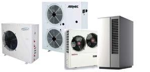
Air to water heat pumps (ATWHP) on the other hand have come a long way in recent years and can offer a much more cost-effective alternative for many structures, big or small, residential or commercial. Heat pumps, unlike boilers, can be reversed to provide cooled fluid for cooling applications in the summer to make this generation of equipment usable all year round. Heat pumps can also provide domestic hot water for a building.
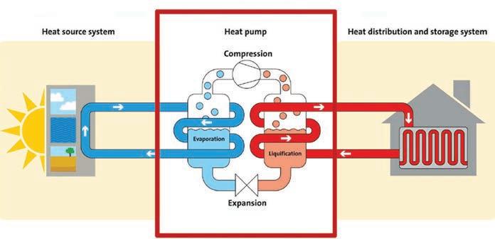
Figure 1. a very basic description of the refrigerant cycle in a heat pump.
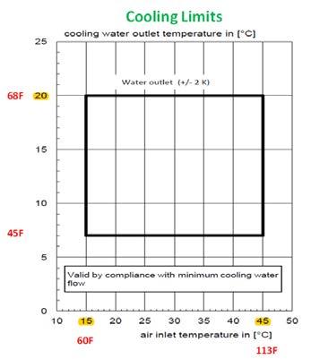
Figure 2b. cooling limits
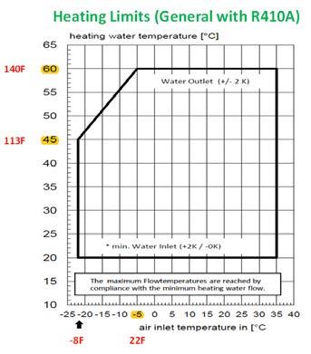
Figure 2a. heating limits
Figure 1 illustrates a very basic heat pump cycle consisting of a source (outdoors), a load (building or fluid storage) and the guts that makes it all happen, including the evaporator, compressor, liquefier and expansion valve.
Refrigerant pressure changes its ability to absorb heat or cool and either put heat into the building in heating mode or pull it from the building and put it outdoors in cooling mode. A reversing valve in the heat pump is used to make the cycle responsive for heating or cooling needs, depending on the requirement.
Using outdoor air as a source of energy is limited to ambient conditions. Today many ATWHPs have inverter driven compressors for added efficiency that can modulate to draw energy out of the ambient outdoors as long as it is above -22C (-8F) for heating operation and below 45C (113F) for cooling operation. That’s a pretty wide range, but in many of our regions some additional backup heat generation is required to supplement the ATWHP during extremely harsh conditions outside of that range. ATWHPs also have a limited fluid temperature that it can generate. The refrigerant used in most of these systems, R410A, limits its output capacity as described in figures 2a and 2b.
The maximum fluid temperature a typical ATWHP can provide is 60C (140F) in heating mode, but its output capability is reduced when the ambient outdoors drops below -5C (22F) and is somewhat in a linear relationship from there down to about -22C (-8F) with the fluid temperature of 45C (113F), as is shown in figure 2a
In cooling mode, the output capacity is pretty stable and can be anywhere between 7C and 20C (45F and 68F) for fluid temperature as long as the outdoor temperature is below 45C, as is shown in figure 2b. These limits must be considered when choosing the terminal units for heating and cooling of the building.
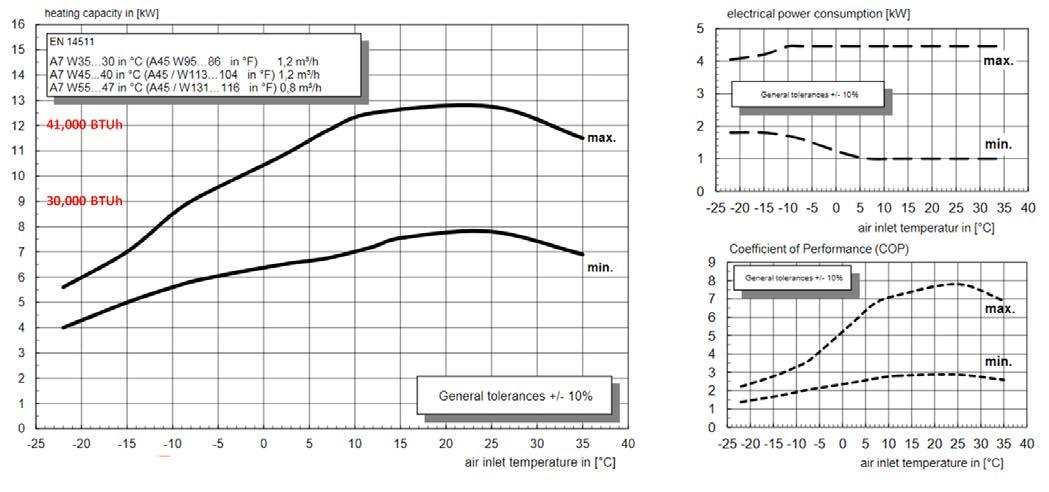
Of course, ambient outdoor temperature and fluid temperature provided affect the output capacity and efficiency of the ATWHP. This can vary from manufacturer to manufacturer, and it is important to understand the ranges when considering your design options and requirements. An example of how it may impact a system is shown in figure 3 for heating.
As the outdoor temperature drops the output capacity drops. In this particular example, at -5C outdoor temperature the output capacity is shown at about
9.5 kW or 32,000 BTUh and operating at a COP of 4. At -20C outdoor temperature, the output capacity is shown at about 6 kW or 20,500 BTUh and now operating at a COP of 2.5.
For the cooling operation, as the outdoor temperature rises the output capacity drops. As an example, at 15C (59F) outdoor temperature the output capacity will be about 14 kW or 4 tons of cooling and operating at an energy efficiency ratio (EER) of 5.5. At 45C (113F) outdoor temperature, the output capacity will be about 7 kW or 2 tons of cooling and operating at a EER of 2.
Understanding these limitations is absolutely necessary when designing a system. In the next issue of HPAC (Part 2 of this article) I will go through a very high level system design example using an ATWHP for a 2,000 sq. ft. home in Canada, looking at mechanical system and control logic that could be employed.
Mike Miller is director of sales, commercial building services, Canada with Taco Inc. and a past chair of the Canadian Hydronics Council (CHC). He can be reached at hydronicsmike@tacocomfort.com.
Figure 3.
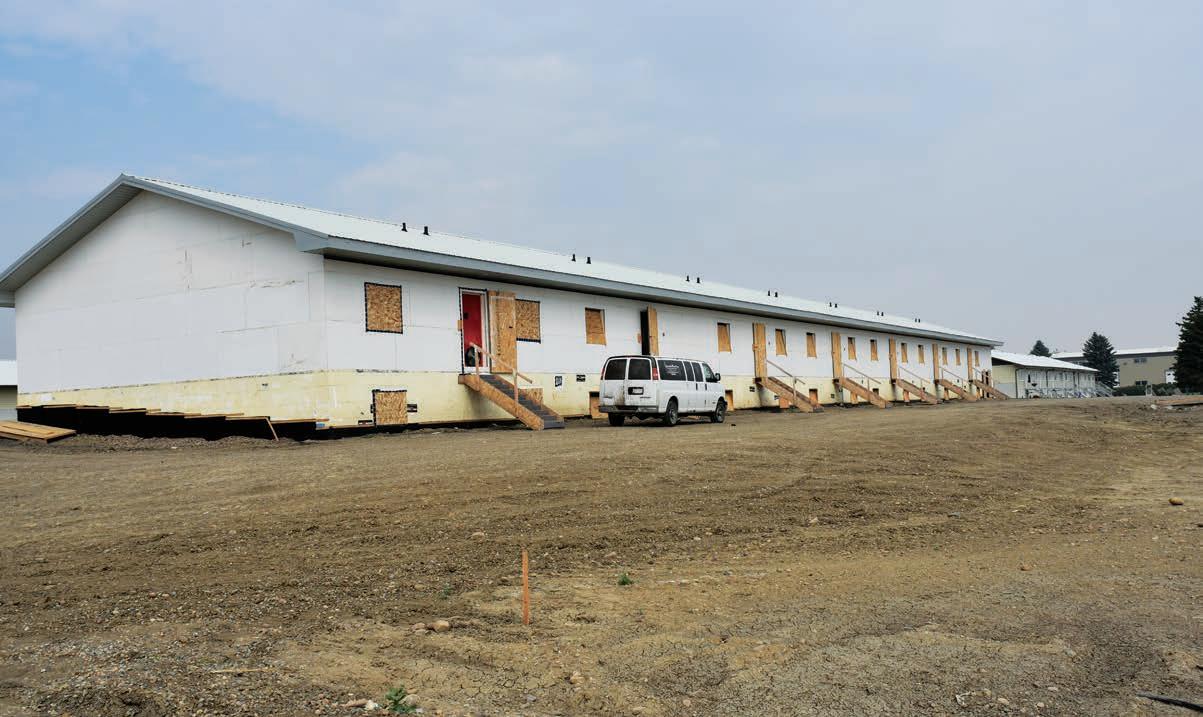
Figure 1: Conservative and practical architecture offers long-term resiliency and simplified control over noise, thermal transfer, air and light. Note the landscaping and foundation drainage plane to mitigate moisture issue and the low window-to-wall ratio to control sound, light, solar gains and radiant asymmetry and drafts.
INTEGRATED DESIGN
A case study in achieving IEQ and efficiency with human factor.
BY ROBERT BEAN
Iwas recently in Vancouver participating as a guest speaker at an integrated design process (IDP) workshop held at the British Columbia Institute of Technology (BCIT) High Performance Building Lab. The event was a collaboration of BC Housing with BC Hydro, FortisBC and the Province of BC. The day-long function was facilitated by Andy Oding from Building Knowledge Canada and Gary Hamer from BC Hydro. There is no single right or wrong definition of an of an IDP, and for the purposes of the workshop BC Housing’s Wilma Leung identified the group’s objectives as:
1. Describe, test, and refine an IDP that can be used to optimize the design of a home that will serve occupants for 100-200 years;
2. Describe the attributes of a home that is built to serve the needs of the occupants—including comfort, health and safety;
3. Agree upon the essential participants needed for a design charrette (IDP professionals) and the role of the engineer/ architect in leading the builder’s team process to deliver high performance/net zero homes.
I have worked on integrated design teams on many projects and see the process much like a business planning process I have used for years: It begins by identifying the business’s compass (the geography of the playing field and its sense of direction). Then you identify its purpose (why does it exist?), supported by a collections of visions (the pieces of the puzzle that must be achieved in order to fulfill the purpose). Those visions are achieved by a combination of executed strategies (the “what” that needs to happen to make the visions a reality) and tactics (the “work” required to complete the strategy) and goals (the “when” for the time-driven tactics). It is an integrated business planning method that is transparent, easy to
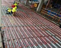
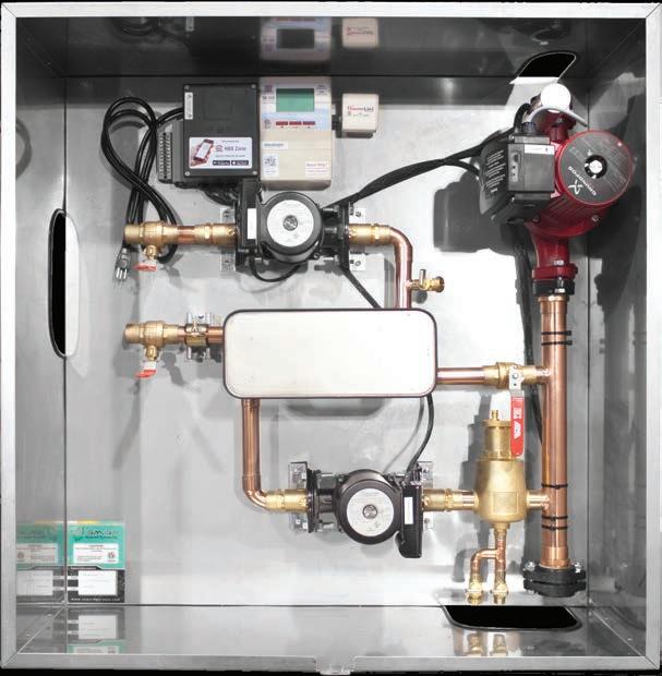
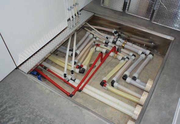
Figure 2: PEXa piping vaults in each unit supply heating, cooling and domestic hot and cold water (expansion loops shown).
understand and it works; and as I’ve discovered, it applies to the design and construction of buildings.
I have written before about the evils of the traditional design process where the architect/builder/owner segregates the project professionals.1 With the IDP it is all about integrating knowledge through the collaboration of the experts.
The differences are important. In the traditional method the building design is typically based on compliance with the minimum requirements of mandatory codes written for safety and reducing the risk of illness. However, with an IDP (in my experience) it adopts human based indoor environmental quality (IEQ) standards and philosophies around sustainability and earth stewardship. As noted by Pearl (2004), “In professional practice, IDP has a significant impact on the makeup and roleplaying of the initial design team. The client takes a more active role than usual, the architect becomes a team leader rather than the sole form-giver,
and the structural, mechanical and electrical engineers take on active roles at early design stages. The team includes an energy specialist (simulator) and hopefully, a bio-climatic engineer.”2
CASE STUDY
To prove a classic example of an IDP consider a project we engineered a few years ago. This case study was an 88,000 sq. ft. (8175.47m²) multi-family project comprised of 28 new homes in four buildings (Figure 1). Two identical mechanical rooms were designed, each serving 14 units.
BACKGROUND
The client is a farming community with a philosophy of building for the long term. They lead a very conservative life with few personal luxuries. The exception is in the design and fabrication of their, “state
of the art” farm buildings, equipment, systems and housing. Here the focus is on resiliency, minimal maintenance, hygiene and indoor environmental quality (IEQ). The architecture is very much antiflamboyant and pro-practical.
Using IEQ for the project ethos drove the compartmentalization of each unit. Each unit is served by independent hybrid HVAC systems using heated and chilled water from the central plants (Figures 3 and 4).
Since the community is sharing resources, including common walls between units, sound privacy is of utmost importance. There can be upwards of seven family members per unit, as such flanking paths needed to be mitigated by non-continuous flooring and wall assemblies.
There can also be outdoor noise issues
Continued on MH18
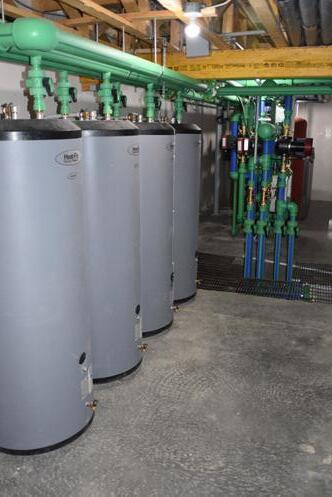
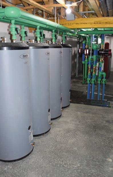
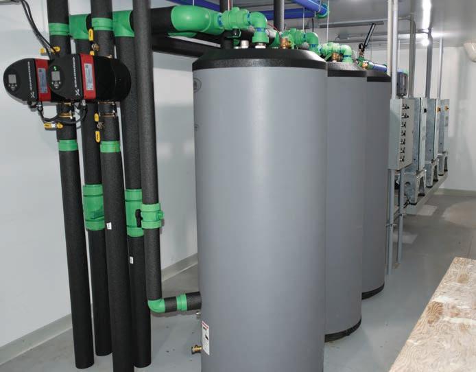
Figure 3: One of two central mechanical rooms for generating heated water for space heating and domestic hot water.
when farm equipment is used near the housing units. Here the enclosure design (conservative window-to-wall ratio, reduced bridging and infiltration) was important to reduce outdoor sound effects. These floor, wall and ceiling details also helped the thermal performance in controlling the mean radiant temperature and thus the operative temperature in compliance with ASHRAE Standard 55 Thermal Environmental Conditions for Human Occupancy.
Lighting quality included window design for achieving acceptable daylight factors which also reduced sound transmission, radiant asymmetry and down drafts; and the design contributed to improved indoor air quality by minimizing the destruction of interior finishes due to exposure to shortwave (solar) radiation. The latter principle is a source control requirement implied in ASHRAE Standard 62.2 Ventilation and Acceptable Indoor Air Quality in Residential Buildings and CSA F326 Residential Mechanical Ventilation Systems.
Air quality strategies also included reducing potential for moisture-related damage (through landscaping, enclosure
designs and ventilation systems) and the use of low VOC finishes, radon mitigation systems and high-quality filtration products.
Odours and vibration are real problems in these types of communities due to agriculture production. Within the homes, internally-generated odours are prevented from migrating to another unit by the compartmentalization details and each unit’s independent exhaust and make up air systems. These details are important since pressure differentials across a common wall created by the operation of exhaust fan(s) could pull odours from one unit into another. However, the most challenging odour issue is related to the hog, poultry and cattle production and outdoor intakes for each home’s ventilation system.
In this dynamic the first source of control is within the production facility itself and then using specialty filtration within each housing unit. Though it’s almost impossible to keep an odour-free environment with natural ventilation, especially during the summer, the community understands some farming odours are part of their culture. Vibration from heavy farm
of 28 mechanical rooms, one in each
machinery can sometimes be a problem mitigated by properly constructed roadways bypassing the housing complex.
PROJECT SPECIFICS
Building Systems:
• Below grade enclosure is 11-in. (280mm) ICF basement walls.
• 4-in. (100mm) slab bears on 2-in. (50mm) of rigid XPS insulation on a gravel radon plenum.
• Interior wood frame walls sheathed with OSB and then finished with drywall.
• Above grade walls are 6-in. (150mm) EPS panels with thermally isolated studs.
• Walls are vapour barriered, sealed and finished on the inside with drywall, and outside with weather barrier, strapping and PVC siding.
• The roof is assembled with engineered
with the radiant control closet to the left, air systems at the top and piping vault at the bottom. The central plants (Figures 3 and 4) eliminated 28 gas lines, venting and combustion air set ups; they also eliminated 28 heating and cooling plants and associated expansion tanks and fill assemblies. Continued on MH20
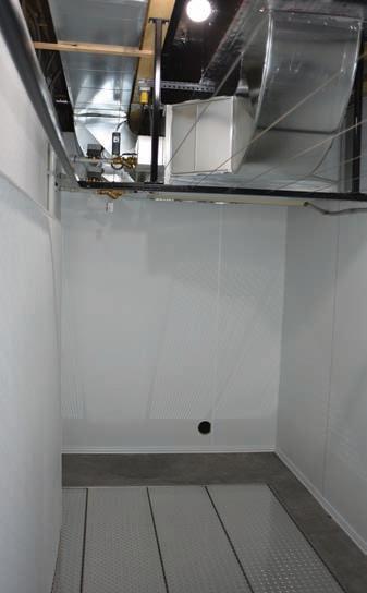
Figure 4: One of two mechanical rooms for generating chilled water for space cooling.
One
unit,
THE FOR RADIANT EASY INSULATION HEAT
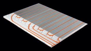
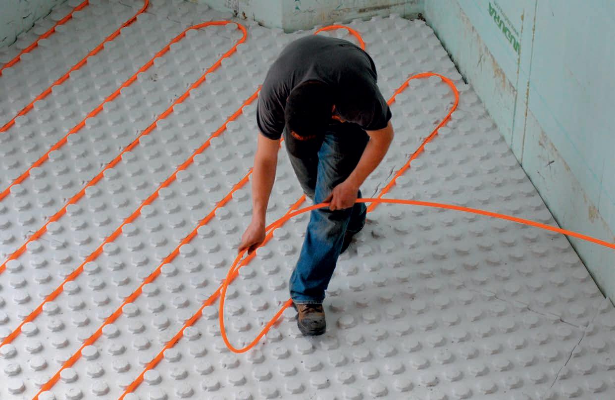
The floor of a building is often the most ignored surface when it comes to insulation. The floor, when insulated with HYDROFOAM®, completes the building envelope and increases comfort and energy efficiency.
HYDROFOAM® maximizes radiant floor heating by ensuring the heat is dispersed evenly throughout the entire floor area, providing building occupants with a comfortable living and working environment.
HYDROFOAM® is the ideal radiant floor insulation product for residential and commercial construction projects. Visit nudura/hydrofoam.com today to start your next project!
TABLE 1. INTEGRATED DESIGN PROCESS AND PROFESSIONALS ROLE IN IEQ ELEMENTS
Sound Reducing transmission of outdoor sounds by minimizing strategically placed openings and designing simplified geometries.
Thermal Reducing transmission of heat and moisture by minimizing openings, reducing solar loads with external shading and designing simplified geometries.
Air
Reducing infiltration by minimizing openings and designing simplified geometries.
Light Reducing excessive natural light using conservative WWR and proper shading.
Odour Reducing infiltration by minimizing openings and designing simplified geometries.
Vibration Reduce or drop complex geometries to simplify vibration control.
Reducing transmission of outdoor sounds through openings and assembly details.
Controlling heat and moisture flows across floor, wall and roof/ceiling assemblies using climate appropriate strategies and tactics including low SHGC.
Reducing transmission of outdoor moisture and particulate through openings and assembly details.
Strategic choices in visible light transmission through windows, doors and skylights.
Reducing transmission of outdoor odours through openings and assemblies.
Reducing transmission of external sources of vibrations through enclosure members.
wood trusses, sheathed and finished with steel roofing. The attic is sealed with a polyethylene membrane, open cell spray foam and filled with cellulose.
• All PVC windows are triple sealed, triple pane and argon filled. Window glass with frame rated at U=0.14 Btu/ft² h F (0.79 W/m²K).
MECHANICAL PLANTS
The heating boilers serve the low temperature radiant floor systems and make up air heating coils. Both are designed to operate on reset with maxi -
Reducing sound from motors and fluid flow through pipes, ducts, valves and dampers, registers, relays and contacts in controls.
Regulating heating and cooling operative temperatures and humidity, air velocity etc. to offset internal loads and loads through enclosure.
Conditioning of air for gases, odours and particulate, controlling moisture and air velocity.
Lighting loads that may have a thermal signature contributing to cooling loads.
Transfer of return air flow having odours, strategic choices in filtration.
Mounting of equipment with motors and fluid flow through pipes, ducts, valves and dampers
mum supply of 120F (49C) and a 20F (11C) differential at design conditions of -35F (-37C). Boilers are also domestic water prioritized, staged to switch to 180F (82C) for charging the four 120 gal (454L) storage tanks through a preheat/boost/reheat brazed plate heat exchanger system for an 80F (44C) rise.
The cooling coils were specified by the client for a 45F (7C) entering fluid temperature and a 10F (6C) rise for conditioning the space and make up air. Cooling airflow per unit is 700 cfm (330L/s) at 1 ton/1200 ft2 (3.5 kW/112m2) based on 2200 ft2 (204m2) of cooled space.
Reducing sound through strategic choices in electrical systems (i.e., motors, lights) and attachment of same to structural members.
Strategic choices in lights and appliances with low thermal signatures affecting heating and cooling loads.
Reducing sound through strategic choices in interior acoustic systems, materials of construction and installation methods.
Strategic choices in flooring affecting contact co-efficient affecting thermal comfort to feet.
Power loads for HVAC equipment and systems.
Strategic choices in lighting devices and systems.
Prevention of overloaded circuits or over heated conduit which can emit unique odours.
Minimizing vibration through motors and lighting systems.
Strategic choices in interior systems, materials of construction and installation methods, i.e., low VOC materials.
Strategic choices in general and task lighting.
Strategic choices in interior systems, materials of construction and installation methods.
Strategic attachments of systems and fixtures to structural members.
Ventilation is comprised of a centrallylocated variable speed in-line primary exhaust fan operating at 105 cfm (71 L/s) at 50% of total design exhaust flow. Ceiling located bathroom fans and range hoods provide additional exhaust capacity in conjunction with a unique odour exhaust system connected to each toilet.
The exhaust systems pull makeup air through an outdoor duct connected into the return air plenum. This air flow passes across the heating and cooling coils of the fan/coil unit for distribution through the supply air system when the
fan/coil blower is off. The temperature regulation of the makeup air and air for cooling is done with a unique non-electric auto heat/cool change-over control—the control modulating fluid flow to each of the coils to maintain a clientcontrolled set point.
A room thermostat is used to turn on the blower on call for cooling (or optional stand by heating). Primary heating is radiant floors but in the shoulder seasons can be done with the fan/coil if the occupants wish to use it for the occasional cold spell.
Heated, chilled and domestic water from the central plants to each of the houses is carried through an in-ground PEX distribution network running under the building. Each home is fitted with a piping vault in the basement floor offering access to the pipes and expansion joints (see Figure 2, page MH16)
FINAL THOUGHTS
Every project I have been involved with using an IDP has always resulted in better outcomes. The buildings provide higher indoor environmental quality using less energy, and the energy used is of the highest efficiency possible for the conditions.
The projects usually followed construction schedules and were completed on time. Often the capital cost premium was only slightly higher than normal because the client was willing to trade off expensive “short term” aesthetics for more practical solutions delivering better “lifetime” outcomes.
To help complete the message on how each profession plays a role in IEQ see Table 1. When one sees how integrated the service providers are to an IEQ metric one begins to understand how antiquated traditional segregated processes are and why they deliver such poor out-
comes. Just like in business, everything is related and everything matters. <>
NOTES:
1. Bean, R. (2014) Integrating Elements to Improve Comfort; Design wholeness can be achieved by proficiency in energy, environmental standards and guidelines. HPAC Magazine Canada. Accessed 2020.01.01 https://www.hpacmag.com/features/integrating-elements-to-improve-comfort/
2. Pearl, D. (2004) An Integrated Design Process (IDP) Canadian Architecture. Accessed 2020.01.01 https://www.canadianarchitect. com/an-integrated-design-process-idp/
Robert Bean is director of www.healthyheating.com, and founder of Indoor Climate Consultants Inc. He is a retired engineering technology professional (ASET and APEGA) who specialized in the design of indoor environments and high performance building systems.
CONSIDERATIONS FOR OPERATING HYBRID RADIANT-DOAS SYSTEMS
Designing for comfort and efficiency in commercial buildings through optimized controls of a hybrid system.
BY SANJIL KARKI
HVAC system designers do not need to choose between comfort and efficiency in commercial buildings. By integrating a radiant heating/cooling system with a dedicated outdoor air system (DOAS), both of these performance attributes can be optimized. This technology decouples sensible and latent loads, allowing the key variables that optimize comfort and energy efficiency to be independently and precisely controlled.
The potential synergy of hybrid radiant-DOAS systems is underutilized. This article discusses three important considerations for designing a sequence of operations that makes the most of this technology.
RADIANT SYSTEM CONTROL STRATEGY DURING SHOULDER SEASONS
A hydronic radiant floor system is controlled by changing either supply water temperature or supply water mass flow rate. Typically, outdoor temperature reset controls are used to modulate the supply water temperature based on outdoor air temperature and control the water flow rate to each room according to setpoint temperature. The average system supply
temperature should also be controlled for faster and more consistent operation.
A typical radiant heating system is designed to a handle space load up to 32 Btu/h-ft 2 (100 W/m2) with a maximum allowable slab temperature as per ASHRAE Standard 55 of 85F (29.4C). A radiant cooling system can provide a cooling capacity up to 14 Btu/h-ft 2 (44 W/m2) with latent loads and supplemental cooling typically provided by a DOAS system. In areas with high direct solar loads, the system’s capacity can significantly increase up to 25 Btu/h-ft 2 (79 W/m2), but accounting for this transient capacity is not always advisable from a system sizing standpoint. For comfort,
ASHRAE Standard 55 mandates a minimum radiant cooling slab temperature of 66F (18.9C).
During shoulder seasons, between heating and cooling modes, what is the best way to control the radiant system? Research by the Center for the Built Environment (CBE) at the University of California Berkeley reached the following conclusion: If the building has a lot of exposed thermal mass and a well-designed envelope, there are no times of the year when heating is required in the morning and cooling required in the evening. These types of buildings respond more closely to the 24-hr average of the outside air temperature conditions and
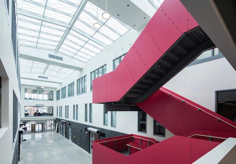
Radiant heating/cooling has been combined with DOAS at Sheridan College Davis Campus (Brampton, Ont.). Pictured: the three-story atrium at the Skilled Trade Centre. (source: REHAU)
can coast through shoulder season days on thermal mass.
DOAS SUPPLY AIR TEMPERATURE CONTROL STRATEGY
Radiant systems provide sensible cooling/heating and are typically configured as a hybrid with an air system, which is used for ventilation, dehumidification and supplemental cooling/heating, if needed. Typically, radiant does the heavy lifting to maintain the sensible load, by warming or cooling surfaces in the space. DOAS is primarily focused on latent loads, but can assist with sensible loads on summer and winter design days, depending on the project.
In cooling mode, DOAS dehumidifies and delivers the required amount of outdoor air conditioned to handle the latent load of both the outdoor air and the space. This requires a supply air dew-point lower than the room air dew-point, typically 48-50F (8.9-10C).
DOAS handles the entire latent load and radiant is only responsible for sensible cooling. This decoupling of the space sensible load from the latent load affords precise humidity control regardless of space thermal load. Humidity control problems often associated with part-load operating conditions are manageable and designers can easily prevent condensation in the space, even in humid cities such as Windsor, Ont.
The supply air temperature of the DOAS is an important factor in achieving maximum energy savings. To handle the entire latent load, the supply air must be dehumidified to a dew point that is lower than space, which typically means overcooling the outdoor air. Designers must choose between supplying air at “space neutral” or “cold air” condition straight off the cooling coil.
When “space neutral” air is supplied, the dehumidified air must be reheated to introduce fresh air into space without affecting the thermal loads, thus wasting all the sensible cooling done during dehumidification. When “cold air” is supplied, the air coming from the unit does not require reheating. With the outdoor air handling some of the sensible cooling, annual energy consumption of the local HVAC unit is significantly reduced.
One control strategy that can be implemented is resetting the discharge temperature based on outdoor air. When outdoor air conditions are such that overcooling is likely, the supply air is reheated to a neutral temperature. This can be accomplished using a microprocessor controller such as a direct digital control (DDC) for discharge air control; the DDC controller monitors the ambient temperature and resets the discharge temperature of the outdoor air unit accordingly.
A more advanced approach to this strategy is to implement a building management system (BMS) that can monitor multiple spaces and determine the “critical space.” Once the critical space is determined, the BMS can adjust the reheat capacity of the outdoor air unit to prevent the critical space
from being overcooled or overheated.
Another controls strategy for saving energy is to utilize humidistats and dehumidification in critical spaces. If the humidity begins trending up, the humidistat sends a signal to the controller that more dehumidification is needed. The controller then lowers the discharge dew point of the outdoor air unit for further dehumidification. Once the room humidity reaches an acceptable level, the dew point is reset back to normal operation.
ZERO-ENERGY-BUILDING (ZEB) TRENDS
Beginning with Vancouver, more than a dozen Canadian cities have taken steps toward the ambitious goal of 100% renewable energy. Last year, Berkeley, California became the first American city to ban natural gas infrastructure in new buildings after PG&E, the second-largest U.S. utility and notably, both a gas and electric utility, publicly supported the move. These cities are part of
Continued on MH24
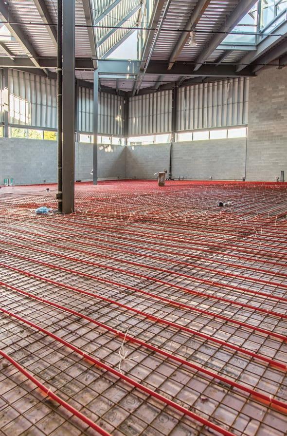
Radiant heating/cooling system being installed in Sheridan College Skilled Trade Center. (source: Klimatrol Environmental Systems Ltd.)
SYSTEM DESIGN
an international trend that will cut natural gas demand through building electrification, swapping out fossil-fuel-powered appliances for electric appliances.
With electrification, engineers are challenged to design HVAC systems that can provide efficient space conditioning without being penalized on utility bills. Heat pumps integrated with hydronic radiant are important components of ZEB design. By extracting heat from a lower temperature source and transferring it to a higher temperature source, modern heat pumps use 66 to 75% less energy than electric resistance heating/cooling appliances.
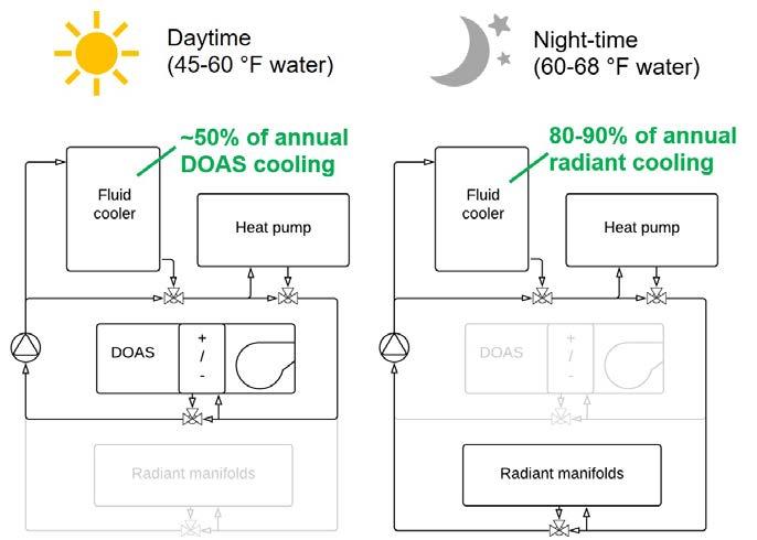
CBE’s all-electric design concept (figure 1) uses an air-to-water or groundsource heat pump, a DOAS system, a fluid cooler or closed-circuit cooling tower and a radiant system. At night, the heat pump provides warm or cool water to the radiant slab depending on the season. At the end of each day’s occupied period, the system gets feedback from the previous-day slab temperature and the controller gradually changes the slab setpoint during the next 12 hours. In this
way, the controller gradually responds to changes in the zone loads over the course of several days. These designs provide excellent hydronic system energy efficiency while being all-electric.
For example, if the previous day’s outdoor condition is 90F (18.9C), the radiant slab will be in cooling mode. The heat pump will generate 60-68F (15.620C) water that will be circulated through the radiant slab during the night, pre-cooling the slab.
As the occupants arrive in the morning, the slab begins absorbing heat from the space and DOAS begins providing ventilation. If the outdoor air needs to be dehumidified, then the heat pump will provide 45-60F (7.2-15.6C) water to the DOAS system. As the day progresses, the radiant slab slowly absorbs heat from the space. If the radiant system is not able to handle all of the cooling load, the DOAS system could then provide supplemental cooling using the chilled water from the same heat pump.
During milder weather, the closed-circuit cooling tower or fluid cooler is used for water-side economizer operation,
providing an additional 80-90% savings on the radiant cooling system.
Since the same heat pump is providing warm or cool water to radiant during the night and DOAS during the day, the mechanical plant size is significantly reduced. Another key benefit of this design is shifting the heating and cooling loads from peak to off-peak hours when utility rates and demand charges are lowest. Heat pump water temperature and savings will vary depending upon project location.
By addressing shoulder season variations, DOAS supply air temperature and meeting the market trajectory toward electrification, a well-designed hybrid radiant-DOAS system does not need to compromise comfort and controllability to optimize energy efficiency. From sequence of operations to building specification, these factors allow radiant and air-side systems to each do what they do best, even in ZEB designs. <>
Sanjil Karki is an engineering sales specialist for the building solutions division of REHAU, responsible for western United States, Alaska and Hawaii. In this role, he educates engineers and commercial contractors on radiant heating and cooling, snow and ice melting, PEX plumbing and geo-exchange systems. Karki serves on the advisory team of “Optimizing Radiant Systems,” an initiative of the Center for the Built Environment (CBE) at the University of California Berkeley.
SOURCES:
Lehrer, D., “CBE Rad Tool Enables Better Design of High-Mass Radiant Systems,” CBE, 16 April 2019, cbe.berkeley.edu/centerline/ cbe-rad-tool-enables-better-design-of-highmass-radiant-systems/.
Bauman, F., Raftery, P., and Karmann, C. “Lessons learned from field monitoring of two radiant slab office buildings in California.” Energy Procedia, 2015. 78, 3031–3036.
Feng, J. (Dove), Chuang, F., Borrelli, F., and Bauman, F. “Model predictive control of radiant slab systems with evaporative cooling sources.” Energy Build, 2015. 87, 199–210. Romaní, J., de Gracia, A., and Cabeza, L.F. “Simulation and control of thermally activated building systems (TABS).” Energy Build, 2016. 127, 22–42.
Figure 1: Example of all-electric design concept for high thermal mass radiant systems operating in cooling mode. This strategy leverages thermal mass to significantly reduce heating/cooling demand and utility cost, eliminating fossil fuels and approaching ZEB targets.
THE
THE ORIGINAL INNOVATORS DELIVER THE FUTURE IN HIGH-EFFICIENCY BOILERS
An all-stainless steel fire tube heat exchanger available in three Solo sizes - 110, 155, 199, and two Combi sizes - 155 and 199.
LOWER PRICE POINT
BREAKTHROUGH MARKET-LEADING WARRANTY PROGRAM with up to 6-year part, 3- year labor and 10-year heat exchanger warranty
ENHANCED QUALITY CONTROL and built with reliability in mind
Learn more about our Three-Point Warranty Program at our website.
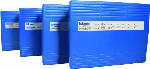
Temkar now offers four new switching relay and zone valve control models to its fleet: 2-zone pumps; 3-zone pumps; 3-zone valves and 5-zone valves. All four models are compatible with low-voltage thermostats and are fitted with RoomResponse, which automatically adjusts boiler temperatures to improve comfort and save energy. Other notable features include unlimited expansion, exercising to prevent pumps from seizing, zone priority and priority override to protect homes from freezing during the winter months. www.tekmarcontrols.com
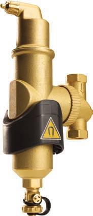
Spirotherm uses magnet technology to separate ferrous and non-ferrous air debris with its Spirocombi Magnet air eliminator. It can be installed horizontally or vertically on both traditional and wall-mount boiler systems. It is available in ¾-in., 1-in., 1
¼-in., 1 ½-in and 2-in. sizes and comes with threaded, sweat and press fit connection options. www.spirotherm.com
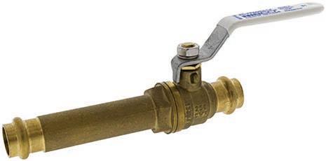
NIBCO has expanded its press valve line to include the Press Slip Ball Valve (PC-FP600A-S-LF). It is easy to install and is designed to adhere to existing copper piping. The PC-FP600A-S-LF is suitable for HVAC and domestic hot and cold water applications. It also has a patented leak detection feature rated to 250 psi Cold Working Pressure. www.nibco.com
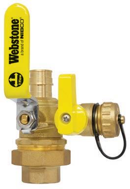
Webstone’s Pro Pal Ball Drain is now available in F1960 and F1807 end connections. The full Ball Drain lineup features FIP, SWT, Press, Press x Pex, PP-R, PP-RCT and union connections, in sizes ½ to 2-in. It features lead-free dezincification-resistant brass construction certified to all appropriate codes and standards. www.webstonevalves.com
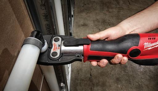
Milwaukee Tools’ new PEX Clip Jaws system is designed to increase the capability of the M12 and M18 FORCELOGIC press tools for F1807 and F2159 PEX. Engineered with user comfort in mind, the PEX Crimp Jaws are designed to eliminate the repetitive strain required of other handheld tools. www.milwaukeetool.ca
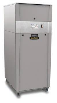
The LAARS OmniTherm series of near condensing boilers and volume water heaters come equipped with electronic airto-fuel ratio control, stainless steel heat exchangers and the Laars Linc icon-driven control system. OmniTherm units can be installed in Category I, II, III or IV vent systems for new or replacement system applications. An intuitive control system features a colour touchscreen. The control system also comes with a quick start option and a USB input for parameter upload. It connects to building automation systems via BACnet. The OmniTherm boiler systems are available in six sizes ranging from 1250 to 3000 MBH. The unit itself offers up to 7:1 turndown and thermal efficiencies up to 87 per cent . It can also be installed in low return water temperature applications. www.laars.com
HEAD VS. ∆P
Important differences between two commonly used terms.
BY JOHN SIEGENTHALER
Those who have worked with the technical side of hydronics have likely used terms such as: pressure, differential pressure, head and head loss. These terms all have legitimate and specific meanings. But when some of these words get scrambled into jargon the result can be an undefined or meaningless term. One example of such a scramble is “head pressure.”
To see why the phrase “head pressure” is not a valid technical term it’s important to understand both words.
Let’s start with head. Although I don’t know who coined this word for use in fluid mechanics, I do know where the concept that the word represents came from. It’s attributable to a Swiss mathematician named Daniel Bernoulli. In 1738 he published a book entitled Hydrodynamica which presented a concept that is now embodied in what’s appropriately called Bernoulli’s equation.
Anyone who has studied fluid mechanics has surely come across this equation. It provides the basis for analyzing a wide range of situations: such as a pipeline carrying water from a reservoir to a city, the shape of airplane wings, or—you guessed it—fluid flow in hydronic systems.
Fundamentally, Bernoulli’s equation describes the mechanical energy present in a fluid, and how that energy can be transformed as the fluid changes height, pressure and speed. The “head” of a fluid is simply the total mechanical energy contained in that fluid.
In the case of a closed-loop hydronic system, head energy is added to the fluid
by a circulator. Everything else the fluid flows through (piping, fittings, valves, heat emitters, etc.) removes head energy from the fluid due to the friction present between moving fluid molecules as well as between those molecules and the surfaces they come into contact with.
INVISIBLE BUT REAL
We can’t “see” energy. We can’t see it with our bare eyes, or under a microscope. Think about it, have you ever seen a Btu, a Kilowatt•hour, or a Joule of energy?
Neither have I.
Although we can’t see it directly, we can still detect when energy is added to, or removed from, a material. For example, consider water flowing into a boiler at 140F and leaving that boiler at 155F. If the piping into and out of the boiler were transparent, the water coming out would look identical to the water going in. Yet we know there’s more thermal en -
ergy in 155F water compared to 140F water. The indicator of that additional thermal energy is a temperature rise. When thermal energy is added to a material (and the material doesn’t change phase between being a solid, liquid or gas) the temperature of that material increases. Conversely, when thermal energy is removed from a material, and the material remains in the same phase, its temperature decreases. Thus, a change in temperature is the “evidence” that thermal energy, which we can’t directly see, has been added to or removed from the material.
When it comes to head energy and pressure there’s an analogy to the relationship between thermal energy and temperature. A decrease in pressure is the “evidence” that head energy has been removed from a liquid. An increase in pressure is the evidence that head energy
The Brute FT® Wall Hung Combination Boiler & Water Heater.
The Brute FT® rises to the challenge with outstanding performance and quick response in a compact design. Its modulating technology automatically adjusts fuel usage to match heat demand – saving up to 20% on heating utility bills compared to standard “on-off” boilers!
To find out more about the Brute FT® and other Bradford White products, visit our exclusive For The Pro® website dedicated to the professional. You’ll get:
• Product Information
• Technical Documentation
• Marketing & Sales tools
• Training Videos and more…
Visit bwforthepro.com now.
has been added to the liquid. We can’t see head energy, but we can detect it being added or removed from a liquid by measuring changes in pressure.
In North America the unit used to express head energy is “feet.” The word “feet” has undoubtedly caused a lot of confusion over the years. I know it confused me for a while. Why would energy be expressed in units that are commonly used for distance? Here again past practices have prevailed.
The unit of feet, abbreviated as ft, comes from a mathematical simplification of the units shown in figure 1.
Figure 1:
This arrangement of units would be properly stated as “foot pounds per pound.”
The unit foot pound, abbreviated as ft•lb, is a valid unit of energy, and as such it can be converted into any other valid unit of energy. For example: 1 ft•lb = 0.0012850675 Btu.
Consider water flowing through an operating circulator. In this situation the arrangement of units in figure 1 can be interpreted as the number of ft•lb of mechanical energy added to each pound of water passing through the circulator. Thus, a circulator that happens to be operating at say 10 feet of head is adding 10 ft•lb of mechanical energy to each pound of water passing through the circulator.
So why don’t we say it that way (e.g., the circulator is adding 10 ft•lb of mechanical energy to each lb of water passing through it)? It’s because mathematically the units of lb in the top of the fraction of figure 1 cancels out with the unit of lb in the bottom of the fraction, and thus the only remaining unit is ft. It’s shorter to just state head in feet rather than ft•lb/lb.
If I had a seat at the table when this simplification became the “standard” in the industry, probably back sometime in the 1800s, my vote would have been to
keep it ft•lb/lb. It’s longer, but it better represents the concept of energy per unit weight of liquid.
THE RELATIONSHIP
So how does one determine the amount of head energy added or removed from a fluid based on observed change in pressure? Answer: Use formula 1.
Formula 1:
Where:
H = head (added or removed) in units of (feet)
∆P = change in pressure in units of (psi)
D = density of the fluid in units of (lb/ft3)
144 = a number needed for the units to work correctly
Formula 1 can be used to calculate the head energy added to the fluid when a pressure increase occurs, such as a pressure increase measured across an operating circulator. The formula can also be used to calculate the head energy removed from the fluid when a pressure decrease occurs, such as across any component or group of components connected together in the circuit.
Water at 60F has a density of about 62.4 lb/ft 3. This makes the fraction of (144/62.4) equal to approximately 2.31.
However, the density of water changes significantly with temperature. The density of other liquids, such as solutions of glycol-based antifreeze, is also different from that of water, and also dependent on fluid temperature.
Thus, stating that the head energy exchanged is 2.31 times the pressure change is only an approximation. It gets you in the ballpark, but the best accuracy is still attained when you use formula 1 along with the density of the fluid.
In a hydronic circuit you can determine the density based on the average temperature of the liquid flowing through that circuit.
MEANINGLESS
So back to the jargon of head pressure. Based on what we just discussed these two words, paired together, are analogous to heat temperature, a term that has no meaning in our industry, or any other industry.
Our industry uses plenty of jargon. For example, we might say that the output of a boiler is 80,000 Btu, when what we mean is 80,000 Btu/hr. We might state that the electrical energy used by a small circulator is 50 watts, when what we really mean is that the power demand of the circulator is 50 watts. We may describe a circulator operating with a head pressure of 10 feet when what we mean is a head of 10 feet.
Jargon is usually acceptable, and perhaps even a bit “admirable” when describing hardware. For example, how many mere mortals know what is meant by a blind flange, street ell or bullhead tee?
However, when learning to manage the physics that determines how the system operates jargon often clouds understanding. That leads to uncertainty, lowered confidence and even finger crossing when making design decisions. We’ve all been there at times, and it makes us (or should make us) uncomfortable.
After reading this some may be thinking that I’m “nitpicking” about words that most of us already sort of understand. Why not be specific and take away the words “sort of” in the previous sentence? It’s precise, professional and ultimately profitable. <>
John Siegenthaler, P.E., is a mechanical engineering graduate of Rensselaer Polytechnic Institute and a licensed professional engineer. He has more than 35 years experience in designing modern hydronic heating systems. Siegenthaler’s latest book is Heating with Renewable Energy (see www.hydronicpros.com for more information).
PEX Expansion
Fits all of our most popular products
•Low-lead, dezincification resistant brass alloy for durability.
•Union fittings for fast and easy installation and service.
•Meets the requirements of ASTM F1960 for cold expansion fittings.