EXPLORING THE


EXPLORING THE


HVAC
UPSELLING RESIDENTIAL HVAC ACCESSORIES
Service contractors and technicians have been improving their sales prowess to the benefit of their customers and the profitability of their businesses.
By Ian McTeer
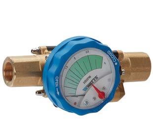
46 COVER STORY PLUMBING THE PLEASURE OF PRESSURE
When domestic water pressure becomes an issue, you have to determine: is it the pressure or the flow?
By Steve Goldie
50
MODERN MOTOR EFFICIENCY
Understanding the added benefits that EM motors bring to the refrigeration industry.
By Dave Demma
52 TECHNOLOGY
GAINING EFFICIENCY AND CONTROL
The introduction of electronically commutated motors changes everything.
By Curtis Bennett
Navigating
MH 4
EXPANSION TANKS
10 DETAILS FOR EXPANSION TANKS
Reviewing important design and installation considerations for a closed loop hydronic system.
By John Siegenthaler
UNINTENDED CONSEQUENCES
The impact of architectural changes on system design.
By Robert Bean
MH 14
GREEN ECONOMY
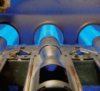
GAS FUELED SYSTEMS UNDER FIRE
Governments are applying pressure on fossil fuel systems.
By Rob Waters
MH 18
OPTIMAL EFFICIENCY
Exploring the proper application and operation of residential ECM circulators.
By Mike Miller
MH 24
SIMPLE AND REPEATABLE
Controlling a renewable heat source combined with an auxiliary heat source.
By John Siegenthaler
MH 22
HYDRONIC PRODUCT SHOWCASE


When a drain cleaning job puts you in a tight spot, using the Power-Vee is like having an extra hand. Just squeeze the feed lever and the Flexicore® cable spins into the line at up to 16 feet per minute. Retracting the cable is just as easy.
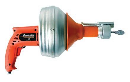
An indispensable tool for any Pro, the Power-Vee, with its quickchange cable cartridge system, durable metal and Dyna-thrust bearings, easily clears sinks, tubs and laundry drains.
Upgrade from manual feed machines. Have a Power-Vee ready for your next tight spot. It puts power in the palm of your hand.
Call the Drain Brains® at 800-245-6200, or visit www.drainbrain.com/powervee
BACK IN MID-MAY, WHICH SEEMS LIKE A LIFETIME AGO, PETER NORMAN, CHIEF ECONOMIST WITH ALTUS GROUP, led an online session hosted by the CIPH and HRAI, and he said that we are in a recession, but “not a regular recession.” And he predicted that “parts of the economy will come back online quickly.”
He cautioned that it could be until early 2021 before the general economy was back on track, but the relatively quick rebound from this health crisis would resemble a V-shaped graph as opposed to a gradual “U” that drags on for years.
Prior to that presentation, when I was speaking with HVAC contractors across the country, they were filled with anxiety; their businesses had dropped off a cliff and the uncertainty of the future was very unsettling.
Now the summer is almost over, and for at least some of those contractors Norman’s prediction was correct – business has come back, and quickly. For them it was a quick “V”.
If I may use a simple plumbing analogy: the taps had been turned off, and now they’re wide open and the sink is almost overflowing.
For some regions of the country a lot of factors combined to create the perfect storm for the residential HVAC industry. While office buildings sit empty, people are working from home and an exceptionally hot July in eastern Canada drove demand for air conditioning maintenance, repair and installation through the roof.
For one contractor I spoke with recently in Ontario, his business is booming and the primary challenge he’s having is getting his hands on new A/C units to fill his customers’ demands.
And despite the hit the economy experienced at the onset of the pandemic, it appears the re-sale housing market in sections of the country has bounced back strong. If my neighbourhood is any indication, houses are selling and renovations are proceeding without hesitation.
New construction, both residential and commercial, has simmered, but as the economy continues to open up it’s anticipated those areas will be placing greater demand on ventilation systems.
And the current back-to-school and back-to-the-office movements are two areas where maintenance and retrofit work to improve air quality will keep HVAC experts busy.
We’re still in the early days of the COVID-19 pandemic, and the anticipated ‘second wave’ of the virus could bring another halt to business activities. But if this recent history has taught us anything, it would seem that the essential services of the plumbing and HVAC/R industry will continue to bounce back. That “V-shaped” recovery could turn into a series of “W”s.
And if I may draw on a sports analogy: any team would be happy with a W. <>
– Doug Picklyk, Editor
HPAC MAGAZINE 111 Gordon Baker Road, Suite 400, Toronto, ON M2H 3R1 TEL: 416.442.5600 FAX: 416.510.5140 www.hpacmag.com
EDITOR
ASSOCIATE PUBLISHER
MEDIA DESIGNER
ACCOUNT COORDINATOR
CIRCULATION MANAGER
PUBLISHER
COO
Doug Picklyk (416) 510-5218
DPicklyk@hpacmag.com
David Skene (416) 510-6884 DSkene@hpacmag.com
Emily Sun esun@annexbusinessmedia.com
Kim Rossiter (416) 510-6794 krossiter@hpacmag.com
Urszula Grzyb (416) 442-5600 ext. 3537 ugrzyb@annexbusinessmedia.com
Peter Leonard (416) 510-6847 PLeonard@hpacmag.com
Scott Jamieson sjamieson@annexbusinessmedia.com
PUBLICATIONS MAIL AGREEMENT NO. 40065710
Heating Plumbing Air Conditioning (established 1925) is published 7 times per year by Annex Publishing & Printing Inc. HPAC Magazine is the leading Canadian business publication for the owner/manager of mechanical contracting businesses and their supply partners.
ISSN: 0017-9418 (Print) ISSN 2371-8536 (Online)
Contents Copyright © 2020 by Annex Publishing & Printing Inc. may not be reprinted without permission.
SUBSCRIBER SERVICES: To subscribe, renew your subscription or to change your address or information please visit us at www.hpacmag.com
Subscription Price per year: $44.00 (plus tax) CDN; Outside Canada per year: $112.00 US; Elsewhere: 1 year $123.00 (CDN); Single copy Canada: $5.00 CDN. Heating Plumbing Air Conditioning is published 7 times per year except for occasional combined, expanded or premium issues, which count as two subscription issues.
MAIL PREFERENCES: From time to time we make our subscription list available to select companies and organizations whose product or service may interest you. If you do not wish your contact information to be made available, please contact us via one of the following methods: Tel: 416-442-5600 ext. 3552, Fax: 416-510-6875 or 416442-2191; E-mail: blao@annexbusinessmedia.com; or by mail: 111 Gordon Baker Rd., Suite 400, Toronto ON M2H 3R1 Annex Privacy Officer Privacy@annexbusinessmedia.com Tel: 800-668-2374
HPAC Magazine receives unsolicited materials (including letters to the editor, press releases, promotional items and images) from time to time. HPAC Magazine, its affiliates and assignees may use, reproduce, publish, re-publish, distribute, store and archive such unsolicited submissions in whole or in part in any form or medium whatsoever, without compensation of any sort.
NOTICE: HPAC Magazine, Annex Publishing & Printing Inc., their staff, officers, directors and shareholders (hence known as the “Publisher”) assume no liability, obligations, or responsibility for claims arising from advertised products. The Publisher also reserves the right to limit liability for editorial errors, omissions and oversights to a printed correction in a subsequent issue. HPAC Magazine’s editorial is written for management level mechanical industry personnel who have documented training in the mechanical fields in which they work. Manufacturers’ printed instructions, datasheets and notices always take precedence to published editorial statements.

Proud member of:


The Canadian Institute of Plumbing & Heating (CIPH) had to pivot to a virtual online format for its 88th Annual General Meeting, held on Tuesday, June 16th. Some 115 member companies were represented at the virtual AGM, which was led by outgoing Chair, Andrew Dyck, the first manufacturer’s agent to hold the position.
The meeting highlights included celebrating the 25th anniversary of CIPH’s partnership with Habitat for Humanity Canada, and the election of Gail Kaufman, vice president of marketing and e-business for Wolseley Canada, as the 73rd Chair of CIPH.
Kaufman joined Wolseley Canada in 2005 in the role of director of marketing. Her CIPH Board experience includes serving on the CMPX Trade Show Committee, the CIPH Women’s Network, Chair of the Charity Committee in support of Habitat for Humanity and Chair of last year’s Annual Business Conference in Charlottetown, themed “Get Connected”.
Outlining her objectives for the year ahead, Kaufman pointed to three areas of focus:
• the need to provide more networking opportunities for members
• building revenue while adding value to members through tradeshows and more
• and hosting events that attract and engage a broader demographic and promote the industry to a wider audience.
The AGM was followed by a keynote session presented by Ian Heller of the Distribution Strategy Group. The talk was entitled, ‘Distribution Will Shift Again, but Not Back to Normal’ and Heller emphasized the growth of online marketplaces, noting in particular the disruption being caused by Amazon Business, which entered the Canadian market in October last year.
After sharing results of a recent survey of distributors and manufacturers in the industry, he made it clear that especially since the COVID-19 pandemic everyone is learning to buy online, so for distributors and sales forces of all types, digital capabilities are no longer optional.
CAPTION:
The Canadian Hydronics Council (CHC) held its virtual Annual Meeting in late June, an online event which included the naming of its new Chair, a presentation on the progress of the National Standards Hydronics

Curriculum, and the announcement of this year’s recipient of the CHC Award of Merit.
Outgoing chair, Dave Hughes (program instructor at NAIT), played a central role in all three aspects of the meeting: handing over the title of Chair to Jason Jackson (a professor at Fleming College in Peterborough, Ont.); leading the curriculum presentation; and being the surprised recipient of the Award of Merit.
Hughes, who completed two consecutive two-year terms as CHC Chair, outlined a few highlights from his tenure including the outcomes from recent strategic planning sessions, which included succession planning objectives and encouraging the recruitment of younger blood into the council leadership. The group’s ongoing liaison position with the Canadian Home Builders Association to build the hydronic industry’s profile was also mentioned, along with the creation of the CHC Conference – the first held last fall in Ottawa and the second planned for Saskatoon in 2021.
The new CHC Chair, Jackson, outlined a few objectives for his upcoming two-year term, which includes building upon the work already accomplished towards establishing a national certification, strengthening the education opportunities for the industry and building greater awareness of the benefits of hydronics to consumers and builders.
The naming of this year’s CHC Award of Merit winner was handled by Mike Miller (Taco, past Chair of CHC) who surprised Hughes when he called out his name.
“I’m not usually without words,” said a stunned Hughes following the announcement.
Launched in 2012, the Award of Merit is the highest honour for an individual in the Canadian hydronics industry.
The event organizers and of the MEET Show, the biennial trade show event in Atlantic Canada, have announced the show has been moved to May 2021.

Originally set for May 2020, and then postponed to November 2020, the show committee has made the decision to hold the MEET Show on May 5 and 6, 2021 at the Moncton Coliseum.
“Although changing these dates wasn’t an easy decision to make, it’s a positive move for the show and we’re ultimately pleased with a spring date,” said Shawn Murphy, show manager, in a media release.
With health guidelines and company policies surrounding international travel uncertain, the event committee felt confident that moving to Spring 2021 was best way to include the widest possible audience. meetshow.ca
Continued on p8
The Government of Canada announced in July its investment of over $200,000 in e-training opportunities for Canadians in the energy efficiency sector, including funding to the Heating, Refrigeration and Air Conditioning Institute of Canada (HRAI) for discounted virtual training courses.
Efficiency Canada, based in Ottawa at Carleton University’s Sustainable Energy Research Centre, is receiving $126,765 to work with the energy efficiency sector to create a training hub that will promote skills training and help Canadians better understand how to transition into the energy efficiency workforce.
The Canadian Institute for Energy Training (CIET) and HRAI will also receive $48,000 and $50,000 respectively for two e-training initiatives.
“The HVACR industry will play an important role in charting Canada’s path to economic recovery and to the important goal of reducing energy use and carbon emissions in homes and buildings across Canada,” said Sandy MacLeod, president and CEO, HRAI, in a Natural Resources Canada media release. “Charting this course will require thoughtful and strategic investments in the workforce of tomorrow. HRAI and its members are grateful for the federal government’s commitment to industry training, and we look forward to continued collaboration in this important partnership.” hrai.ca efficiencycanada.org

The Canada Green Building Council (CaGBC) has announced that the 40 King St. W. tower in downtown Toronto, part of the Scotia Plaza, has earned the Zero Carbon Building (ZCB) –Performance Version 2 certification, making it the first building to certify under CaGBC’s newly updated ZCB Standard v2.
The new certification for the 68-storey, 1.5 million sq. ft. office tower located at the core of Canada’s financial adds to an existing list of achievements for the building including LEED Platinum, Fitwel and WireScored Certified: Gold.
The new designation was celebrated by the property owners KingSett Capital, Alberta Investment Management Corp. (AIMCo) and James Richardson & Sons Limited (JSRL), along with the property management team of BentallGreenOak and lead tenant Scotiabank.
CaGBC president and CEO Thomas Mueller recognized the efforts of the partners in securing the certification, and honoured the building’s ownership: “We congratulate KingSett Capital on achieving Zero Carbon Building –Performance v2 certification, making Scotia Plaza’s 40 King St. W. both the largest ZCB-certified building yet and the very first under the newly updated standard. KingSett’s achievement validates that zero carbon buildings— whether new builds or retrofits—are both technically and financially feasible
for owners willing to innovate and invest in a low carbon future for Canada.”
Scotia Plaza’s 40 King St. W. has a transition plan in place to remove all carbon-intensive mechanical systems over the next 18 months. The building is going beyond the ZCB – Performance v2 certification’s latest zero carbon balance requirements by also offsetting its emissions from waste-to-landfill generated onsite using Gold Standard certified carbon offsets.
With respect to the HVAC set up, according to a building specification sheet, each floor is provided with compartment units servicing only that floor. Conditioned air is supplied to each floor by a variable air volume (VAV) duct system to perimeter slot diffusers and interior zone troffers over light fixtures. Heating is provided by heat reclaimed from the cooling systems, and supplemented by electric boilers.
Cooling is provided by six York centrifugal located in the P4 level mechanical room. They were converted to operate with R123 refrigerant and have a rated capacity of about 650 tons each. CaGBC.org
The first CO 2 -reducing air scrubber installed in a Canadian commercial building is now located in the 10th floor space of 100 Sheppard Avenue East in North York, Ont., the same building that is the new home of Canadian mechanical and electrical consulting engineering firm Smith + Andersen, and Footprint, the environmentally-focused arm of the Smith + Andersen Group.
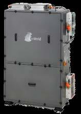
The air scrubber technology used is
the enVerid HVAC Load Reduction (HLR) “smart scrubber” – the AHR Expo Innovation Award-winning technology was developed and provided by enVerid Systems in partnership with O’Dell Associates.
Smith + Andersen and Footprint began exploring the option of an air scrubber installation while planning the relocation of their Toronto teams in 2018. Sustainability was the primary design driver for their new office space, and Manulife, the building's landlord, expressed a shared interest in the potential impact of the technology.
The Smith + Andersen Group moved their Toronto teams to the new site in the summer of 2019, and the enVerid HLR smart scrubber was installed in late December 2019.
The air scrubber contains an adsor bent material that removes particles, hazardous gasses (including CO harmful chemicals (such as formalde hyde and VOCs) from the air.
Through molecular cleaning, the unit can reduce the need for outside air by 60 to 80%, providing a potential 20 to 30% energy cost savings, reducing pol lution and HVAC maintenance, and im proving occupant comfort.
“This is an HVAC technology that has not yet been used in the Canadian mar ket, so it faces the initial battle of “bleeding-edge” technologies,” said Smith + Andersen managing principal Kevin Farbridge in a company release.
Health Canada posted a recall and safety alert for certain Lochinvar condensing gas boilers and condensing gas combi boilers due to risk of carbon monoxide poisoning. The recalled units contain a silicone flue grommet which is fitted through a small hole in the flue pipe and seals and holds a temperature sensor to the flue pipe.
Over time, it may be possible for the silicone to break down, and if this occurs, the vacant mounting hole allows flue gas to escape. Approximately 3,642 units were sold in Canada between Aug. 2016 and June 2020.
Triangle Tube is conducting a voluntary product recall to repair certain boilers. The recall involves 22 models
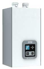
of the Prestige Solo and Prestige Excellence condensing gas boilers manufactured between November 2011 and October 2019. Flue gas can escape from the gas boilers if the vent adapter is not securely reattached to the boiler after maintenance or repair, posing a poisoning hazard.
waterheaterrecall.com/LocBoiler RecallPage
triangletube.com/about/news/recallinformation

“It seemed right to be testing this technology on ourselves as a proof-ofconcept for our clients.”
This air scrubbing system is connected to the building’s Desigo building automation system (Siemens). This connection enables Smith + Andersen and Footprint to monitor air quality, energy savings, HVAC load reductions and cost savings. sa-footprint.com smithandandersen.com
Adrian Steel’s Grip Lock and Drop Down Ladder Racks are designed with ergonomics and user safety in mind. Whether you’re upfitting a single van or an entire fleet, Adrian Steel has just what you need. Increased efficiency starts now.


BY IAN MCTEER
II can still remember most of the parts inventory stocked in my service van long before the day of electronic circuit boards and inverter drive compressors. Here is a sample: box of thermocouples; several thermopiles; pilot burner/aluminum tubing/ferrules; millivolt thermostat/24-volt inexpensive thermostat; millivolt and 24-volt gas valve; quarter and third horsepower fan motors; selection of fan belts/4-in. adjustable drive sheave; shaft and bearings; replacement humidifier pads; selection of condenser fan motor and compressor capacitors; 30-lb. container of R-22; and other odds and ends such as thermostat wire, nuts/bolts/ screws, Schrader valves and so on.
These items, intended mainly for a quick re & re then along to the next one. Some service contractors have been upselling items such as programmable thermostats, humidifiers and electronic air cleaners for many years. Technicians, in days gone by, were not noted for their sales prowess nor could many be both-
ered to spend extra time on the job upselling the customer to a newfangled programmable thermostat.
To say that the operation of a successful HVAC business in today’s cauldron of regulation, taxation and labour shortages is challenging only serves to camouflage the need of everyone in the residential HVAC marketplace to sell their company and its products every day.
Extracting as much revenue from projects typically means upselling smart thermostats, cabinet or bypass air filters, humidifiers and other devices at the front end so that installers can completely accessorize a job in one fell swoop. The so-called enhanced job ticket provides extra commission for salespeople and more profits for business owners.
HVAC businesses can also expect recurring revenue from the sale of maintenance contracts and equipment
servicing. Modern HVAC technicians have become consultants, too. Studies show that consumers will often not only trust, but seek out advice from a professional, qualified and honest technician. Many equipment sales are generated by techs factually demonstrating to frustrated customers that throwing any more money at a unit on its last legs simply is not worth it. When it comes to upselling accessories after the fact or to new service customers, contractors must decide what devices to sell and be sure everyone involved is professionally trained on how the device benefits any given customer. Techs, of course, must be trained to sell it, install it and commission it. It makes no sense to bulk up one’s inventory with devices few employees can or even want to sell.
I have already mentioned that air filters for residential forced warm air systems are often sold up front; technicians aren’t likely to stock a 4-in. MERV 13 cabinet and associated duct fittings on their trucks. However, homeowners often ask techs for advice on better air filtration,

humidification, HRV vs ERV and other indoor air quality related questions.
Certainly, a tech could make recommendations and even sell the IAQ job with an installation crew coming out later to complete the work. I’m thinking technicians are fielding COVID-19 questions every day now and I hope they’re knowledgeable enough to make appropriate recommendations.
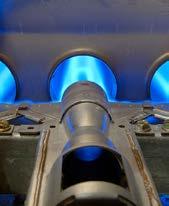
A few facts as of this writing: the air filter in a forced warm air system is not intended to filter-out biological agents, even though it likely does capture some bacteria and viruses. The filter’s primary job is to help keep critical heat exchanger surfaces such as the secondary heat exchanger, evaporator coil and blower wheel from loading-up with dirt.
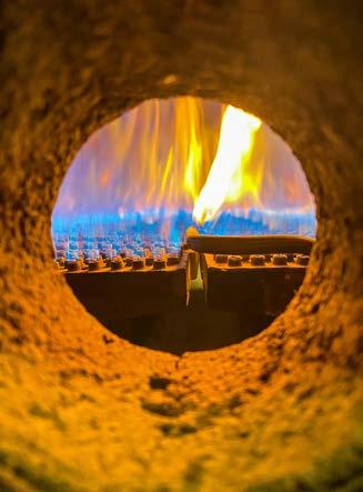
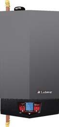
Far too many residential buildings in Ontario and likely elsewhere in Canada were never designed for the greater airflows required of high efficiency gas furnaces, conventional add-on heat pumps or cooling systems. Inadequate return air ducting reduces the effectiveness of high efficiency systems and the addition of restrictive filters often causes equipment damage or poor performance. This MERV 13 filter (Figure 1)) will trap some small particles (62% efficient down to 0.3 microns) but the initial pressure drop in a 1200 cfm three-ton sys-
tem is unacceptable.
Anyone intending to upsell high efficiency filtration must do a survey of the existing system to ensure a cabinet style high efficiency filter can work appropriately. In many cases, improved filtration might come from a HEPA bypass filter manufactured by companies like Amaircare, Five Seasons, Fantech and others.
I am pleased that our industry can promise homeowners significantly improved indoor air quality using several proven strategies. Relief from sometimes life-threatening allergens such as pollen, pet dander, dust and smoke continue to be a mainstay of our industry. Having said that, I am not sure we are ready to offer protection from dangerous viruses. Before COVID-19 took hold in North America, there were already several nasty influenza viruses circulating throughout the population. The Centers for Disease Control (CDC) in the United States said several strains of Influenza A(H1N1)pdm09 and Influenza B/Victoria had already taken many victims. Yet, most residential HVAC contractors made no effort to interdict these viruses.
As of this writing, it is still unknown if COVID-19 can spread throughout a building’s HVAC system. CDC tells us
“Studies show that consumers will ... seek out advice from a technician.”
that the primary mechanism for transmission is through person-to-person contact with small droplets. It is also known that the virus spreads more rapidly in air when the relative humidity is below 40% or above 60%. Thus. improperly sized, short cycling cooling systems leaving excess moisture in the air along with poorly ventilated houses need to be corrected by our industry; however, repairs will be expensive.
Selling a homeowner on a filter capable of removing viruses from the air is not a wise pitch, in my view. Assuming the return air system is even capable of streaming droplets all the way to the filter, should unprotected homeowners or HVAC technicians be expected to change and properly dispose of spent filters potentially containing more viruses than a Level 4 laboratory? Viruses are not alive; they are more like a seed simply waiting for the right set of conditions to present themselves before sprouting their nasty business.
UV-C lights have a long history in our industry and can neutralize many kinds of microorganisms. UV-C disrupts virus DNA rendering it harmless. As a residential upsell, however, the contractor must carefully assess the air handling system including the evaporator coil and ductwork so that sanitizing reflectivity is maximized.
UV-C light is dangerous to the eyes and skin so safety mechanisms to ensure the lights are off during servicing are especially important. UV-C bulbs have a short lifespan, perhaps two years of effective service can be expected in most cases. Again, do the droplets containing the virus make it to
Continued on p12
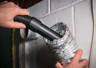
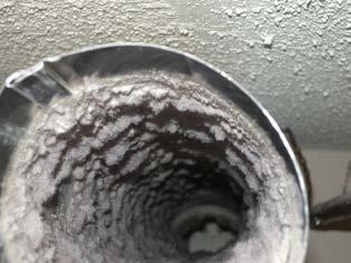
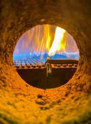
The International Association of Certified Home Inspectors published statistics from the U.S. National Fire Protection Agency (NFPA) that are truly frightening.
In 2005, 13,775 house fires related to clothes dryers caused 15 deaths, 418 injuries and a staggering $196 million in property damage. I haven’t seen any evidence that the incidence of dryer fires has improved over the years, in reality, such tragedies rarely make the daily news.
Standard Vent System Chart
Number of 90˚elbows
Type of vent Angled hoods
0 Rigid metal 64 ft. (20 m)
1 Rigid metal 54 ft. (16.5 m)
2 Rigid metal 44 ft. (13.4 m)
3 Rigid metal 35 ft. (10.7 m)
4 Rigid metal 27 ft. (8.2 m)
As an added service, contractors should consider offering a dryer vent inspection and upgrade program to every homeowner with an electric or gas-fired clothes dryer.
Dryer vents are not part of the HVAC system and might be considered to be none of our business. Companies offering duct cleaning will clean out the dryer vent, but do they offer an inspection service that includes upgrading the vent pipe using material prescribed by the dryer manufacturer?
Homeowners (and others) often make potentially dangerous mistakes when connecting the dryer vent:
• Too often improper material is used
• The vent run has too many elbows
• The vent run is too long
• The vent pipe is too small (still 3-in. material out there) or too big
• The pipe joints are not sealed properly
• The vent hood does not meet manufacturers requirements
Dryer vent material must be UL Listed semi-rigid flex duct or smooth bore rigid metal pipe. Aluminum is best: it’s “slipperier” and resists corrosion.
Typically, semi-rigid ducts are restricted to lengths less than 8 feet
Dryer manufacturers say a 4-in. vent should be able to handle between 100 and 200 cfm at a velocity no less than 1,100 fpm.
Larger ducts should not be used; lint will drop out too easily at lower velocities.
One manufacturer provides back pressure data: using a low range manometer installed into the vent at the dryer outlet connection must read in a range of -1.0” to 0.6” w.c.
Trained HVAC techs can properly test the venting system. Lint will coat aluminum too eventually causing dangerous concentrations of lint to build-up inside the dryer. Lint on the blower wheel increases drying time and energy consumption.
HVAC techs should not be dismantling the dryer unless they’re also trained appliance technicians. Suffice to say that once the vent is upgraded, an appliance technician should be called in to clean out the interior of the dryer. Annual inspection and maintenance is necessary.
the UV light? Perhaps a portable room UV-C filter would be a better upsell.
Another potential upsell that can effectively neutralize viruses along with mold, VOC’s, bacteria and can also oxidize odorous gases without generating any ozone is bipolar ionization. One unit, manufactured by Nu Calgon, mounts in the furnace or air handler blower compartment where the generated ions attach themselves to contaminants thus killing bacteria and neutralizing viruses.
The device allows for a reduced rate of ventilation in non-healthcare situations; however, it does produce some CO2 and water vapour that could, in some instances, throw a wrench into the target ventilation rate.
At this writing, it should be noted that neither the UV-C nor bi-polar ionization device manufacturers are making solid claims of providing protection from the SARS-COV-2 virus that causes the illness known as COVID-19. As a contractor, I would want to see positive results of accelerated testing along with the blessing of organizations such as ASHRAE, Health Canada and the CDC before aggressively upselling such products.
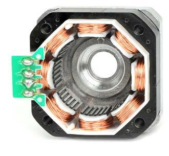
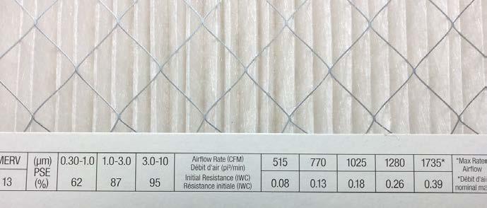
A popular upsell that can reduce electrical energy consumption by the HVAC system is an efficient fan motor such as the Genteq Evergreen or the MARS Azure brushless ECM’s (Figure 2). After upselling a better filtration system to catch dust, dirt, pollen and animal dander, the filter does its best work when the fan motor runs continuously. Yet, this upgrade is tricky because too many duct systems are already restrictive.
Curiously, PSC motors unload in the face of dirty filters and tight duct work, they use less energy whereas a programmed ECM will increase energy consumption to move the programmed amount of air. So, the contractor should

Montreal 9500, boul. Ray-Lawson
Anjou, QC, H1J 1L1
Tel: 514-493-6400
Fax: 514-493-8722
montreal@powrmatic.ca
Quebec
385, Fortin
Quebec, QC, G1M 1B2
Tel: 418-683-2708
Fax: 418-683-8860
quebec@powrmatic.ca
Ottawa 1412, Star Top Rd
Gloucester, ON, K1B 4V7
Tel: 613-230-7160
Fax: 613-230-0685
ottawa@powrmatic.ca
Toronto *new location* 157, Rivermede Rd Vaughan, ON, L4K 3M4
Tel: 905-660-0033
Fax: 905-660-8881
toronto@powrmatic.ca

London 1064, Hargrieve Road
London, ON, N6E 1P5
Tel: 519-675-1491
Fax: 519-675-4725
london@powrmatic.ca
Halifax 100, Wright Ave.
Dartmouth, NS, B3B 1L2
Tel: 902-454-8684
Fax: 902-453-5875
halifax@powrmatic.ca
be looking at duct renovations as an energy saving strategy before upselling expensive motors in some cases.
Many houses built during the boom years, starting in the late ‘60’s in Canada, have been renovated: better windows, doors, extra insulation and high efficiency heating systems have been installed. Yet, like a narrow, twisty gravel road is bad for an exotic sportscar, few older houses have had the proper duct renovations needed to handle the extra airflow requirements of high efficiency HVAC products.
Upselling smart thermostats to customers having WiFi makes good sense for everyone. Remote control capabilities through the internet allow homeowners to control their HVAC from anywhere, even allow for malfunction alerts to be directed to the contractor. Additional devices like remote sensors and an outdoor temperature sensor provide extra comfort and convenience. Some smart thermostats incorporate internet hubs allowing other devices such as smoke alarms and water leak detectors to be incorporated into a smart home system. I especially like the data collection function of smart thermostats (Figure 3) as daily and monthly run time data is invaluable for technicians looking for performance problems.


Perhaps the weakest link in a residential air conditioner or conventional heat pump is the contactor switch. HVAC manufacturers have for many years incorporated very inexpensive contactors typically consisting of an unprotected single pole that suffers significant abuse from its general surroundings.
Although in a sealed electrical compartment, dust and dirt can get in and insects like ants and earwigs love to curl up inside the contacts apparently attracted by the magnetic field generated by the contactor coil. Dead bugs along with dust and dirt electrically insulate the contacts causing arcing, chattering, and damaging voltage drop, this means death in the afternoon for compressors. Even a one volt drop across the contacts is unacceptable. Upgrade the customer’s unit to a device like Emerson’s Smart Switch (Figure 4):
• It’s completely sealed, no bugs, dirt, water, debris can get inside
• The compressor is protected from voltage drop across the contact as well as brownouts and short cycling
• An on-board microprocessor helps to prevent contact pitting and welding
• Test and cycle count functions
Use ferrules at the heavy-duty lugtype line voltage connections and be sure to use an equivalent grade of wire should any existing components need to be moved and rewired.
Consider upselling HVAC surge protec -
tive devices because modern equipment is full of expensive electronic controls (Figure 5 ). Furnace control boards, electronic txv’s, defrost controls, motor control modules, variable speed draft inducer controls and other devices are susceptible.
Considering my old service truck had a few hundred dollars’ worth of needed repair supplies, it is not likely that today’s service technicians are going to carry around a stock of high value inventory waiting for what amounts to an impulse sale, and only if the tech has the time.
Bryan Orr, co-founder of Kalos Services in Clermont, Florida talks about contractor sales: “Sales is something all employees need to be doing with every customer by discovering their needs, fears and desires and then providing them with solutions for which they will pay you.”
Some of the profits generated by multiple revenue streams help to build exceptional companies: there’s more money to better train all staff, money for top drawer pay and benefits, money for the best tools and equipment and money to help weather business related set-backs however caused. Remember: Nothing happens without a sale. <>

Ian McTeer is an HVAC consultant with 35 years experience in the industry. He was most recently a field rep for Trane Canada DSO. McTeer is a refrigeration mechanic and Class 1 Gas technician.
10 EXPANSION TANK POINTERS
OPTIMIZING EFFICIENCY WITH ECM CIRCULATORS

Navigating a ‘low carbon’ economy
RENEWABLE HEAT SOURCE CONTROLS
CONSTRUCTION CHANGES AFFECT DESIGN

4 EXPANSION
10 Details for expansion tanks
Reviewing important design and installation considerations for a closed-loop hydronic system.
BY JOHN SIEGENTHALER
EDITOR
ASSOCIATE PUBLISHER
ACCOUNT COORDINATOR
MEDIA DESIGNER
CIRCULATION MANAGER
PUBLISHER
COO
MH 8 DESIGN Unintended consequences
The impact of architectural changes on system design.
BY ROBERT BEAN
MH 14 GREEN ECONOMY
Gas fueled systems under fire
Governments are applying pressure on fossil fuel systems.
BY ROBERT WATERS
Optimal efficiency
Exploring the proper application and operation of residential ECM circulators.
BY MIKE MILLER
Product showcase
Doug Picklyk (416) 510-5218 DPicklyk@hpacmag.com
David Skene (416) 510-6884 DSkene@hpacmag.com
Kim Rossiter (416) 510-6794 KRossiter@hpacmag.com
Emily Sun esun@annexbusinessmedia.com
Urszula Grzyb (416) 442-5600, ext. 3537 ugrzyb@annexbusinessmedia.com
Peter Leonard (416) 510-6847 PLeonard@hpacmag.com
Scott Jamieson
MH 24 CONTROLS
Simple and repeatable
Controlling a renewable heat source combined with an auxiliary heat source.
BY JOHN SIEGENTHALER


Design and installation aspects to consider.
BY JOHN SIEGENTHALER
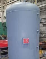
Water in its liquid state, like nearly all physical materials, increases in volume when heated and decreases when cooled. These actions occur at a molecular level. Although it may appear that more water is being “created” as a given volume of water gets heated, that’s not the case. The same number of molecules are present, they’re just taking up more space.
Since water molecules are very small, one might assume that thermal expansion is a “weak” effect. However, that assumption is very wrong. Any attempt to constrain molecular expansion will be met by tremendous forces.
If a strong metal container—such as a hydronic piping system—were to be completely filled with liquid water, sealed from the atmosphere, and heated, it would experience a rapid increase in pressure. If allowed to increase by further heating, the container would eventually burst, in some cases violently. That’s why all closed-loop hydronic systems must have a pressure relief valve.
Since we can’t mechanically “overpower” the expansion of water, we have to accommodate it. We need to give it something to “push” against when heated.
That something is a predetermined volume of air that stays within a closed hydronic system. The container for that air is called an expansion tank.
As the system’s water expands it
pushes against the air in the tank causing it to compress. When the water cools and contracts, the air re-expands.
Today, the most commonly-used expansion tanks use a highly flexible butyl rubber or EPDM diaphragm to completely separate the air and water inside the tank. This diaphragm conforms to the internal surface of the tank when the air side is pressurized (Figure 1)
When the system’s water is heated, the increased volume moves into the tank. The diaphragm moves toward the captive air chamber. The air pressure in the tank increases as does the water pressure in the system. However, if the tank is properly sized, the increase is small and not enough to cause the pressure relief valve to open.
Diaphragm expansion tanks can be sized using charts or software. A detailed procedure for sizing diaphragmtype expansion tanks is given in reference 1 at the end of the article.
There are several design and installation details that should be used to properly incorporate an expansion tank into
a closed-loop hydronic system.
Detail 1: Always make sure the expansion tank connects to the system close to the inlet side of the system’s circulator. This concept was correctly applied decades ago, but then slowly faded from practice as other installation “conveniences” seem to take priority.
The lack of attention to this detail is frequently the cause of chronic air entry into hydronic systems. Experienced hydronic technicians asked to fix systems that require frequent air purging know to check the placement of the expansion tank relative to the circulator inlet as one of the likely causes of the problem.
I’ve known of systems that suffered, from chronic air problems, but were instantly “cured” by repositioning the connection point of the expansion tank near the inlet of the circulator.
The point where the expansion tank connects to the piping system is the only location within the system where the pressure doesn’t change when the circulator is operating. This allows the differential pressure created by the circulator to be added to the static pres -
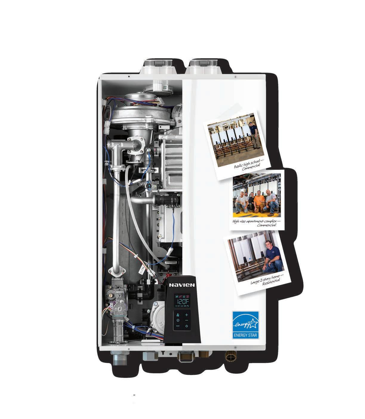
Navien... the PROVEN performer of highly engineered condensing tankless water heaters
Exclusive dual stainless steel heat exchangers resist corrosion better than copper
ComfortFlow ® built-in recirculation pump & buffer tank for NPE-A models
Easier installs with 2" PVC, 1/2" gas and field gas convertibility
Intuitive controls for faster set up, status reports and troubleshooting
Navien... the LEADER in high efficiency condensing tankless innovations since 2012
To learn why Navien NPE tankless is the best selling* condensing brand in North America, visit NavienInc.com
*According to BRG
sure in the system. Increased system pressure helps protect the circulator from cavitation and often allows for quieter operation. It also enhances the ability of air vents to eject air from the system. Figure 2 (below) shows acceptable placements of the tank.
Detail 2: It’s always best to install diaphragm type expansion tanks vertically with the piping connection at the top. This reduces stress on the tank’s connection relative to horizontal mounting. It also prevents air in the piping from getting trapped on the water side of the expansion tank when the system is first filled. The latter can occur when the tank is mounted vertically, but with the connection at the bottom.
Detail 3: The life of an expansion tank depends on system operating temperature, pressure, fluid chemistry and oxygen content. The higher the operating temperature, and the higher the availability of dissolved oxygen in the system’s water, the shorter the expected life of the tank.
When a tank fails due to a ruptured diaphragm or corrosion it’s relatively easy to replace IF the installer provided an isolation valve between the tank and where it connects to the system. Without this valve you may have to drain gallons from the system just to unscrew the failed tank and screw in a new one.
I suggest a ball valve for isolating expansion tanks. After the system is first commissioned remove the handle from this valve and store it somewhere in the mechanical room. This reduces the chance that someone might inadvertently close the valve and thus isolate the tank from the system.
Detail 4: Consider oversizing the expansion tank. The typical tank sizing calculations determine the minimum tank volume. Using a larger tank, although likely more expensive, is fine. Doing so reduces changes in system pressure as the fluid temperature varies. In systems without automatic fluid make-up, such as a circuit operating on antifreeze, extra fluid in an oversized expansion tank helps keep a newly commis -
sioned system operating at adequate pressures as the air separator removes dissolved air from the system.
Detail 5: Plan around the lowest temperature the fluid may achieve. In most hydronic heating systems expansion tank size and air side pressurization is based on the assumption that the cold fluid used to fill the system is in the temperature range of 45 to 60F. That’s fine in most space heating applications. However, when an expansion tank is used in a solar collector circuit, or a snowmelting system, the antifreeze solution will at times be much colder, perhaps even below 0F. If the tank’s diaphragm is fully expanded against the steel shell at a fluid temperature of perhaps 45F, any further cooling of the fluid will likely cause negative pressure in the system, and possible inflow of air from a float-type vent. Reference 2 explains how to correct for this possibility. The concept is to add sufficient fluid to the tank during loop pressurization so the diaphragm is not completely expanded against the inside of the tank until all fluid in the system is at the lowest possible temperature.
Detail 6: Adjust for antifreeze. Solutions of propylene or ethylene glycol have higher coefficients of expansion compared to water. The higher the concentration of antifreeze the greater the expansion volume required. The increase in volume for water heated from 60 to 180F is about 3%. The increase in volume for a 50% solution of propylene glycol heated from 60 to 180F is about 4.5%. This higher expansion rate should be accounted for when sizing tanks for systems such as snowmelting, solar thermal or other applications where glycol-based antifreeze solutions are used.
Detail 7: Never use a standard expansion tank with a carbon steel shell in any type of open loop application, such as a system that uses potable water to carry heat to hydronic heat emitters (which is a bad idea for several other reasons). The elevated dissolved oxygen content of the water will accelerate corrosion of the carbon steel shell. This limitation also applies to closedloop systems using non-barrier PEX tubing or other materials that may allow oxygen diffusion in the system. Expansion tanks with internal polymer linings should be used in any application where higher levels of dissolved oxygen could be present.
Detail 8: Don’t install expansion tanks directly below hydraulic separators. Doing so allows dirt collected at the bottom of the separator to drop into the expansion tank. Over time this could lead to failure of the diaphragm. If the tank needs to be near a hydraulic separator it’s best to mount it from a tee in either pipe connecting to the lower sidewall connections on the separator, as shown in Figure 3.
Detail 9: Whenever possible, avoid locating expansion tanks in proximity to very hot water. When the tank’s shell is heated the pressure of the air in the tank increases. This increases system pressure relative to a situation where the tank shell is cooler and may lead to leakage of the pressure relief valve.
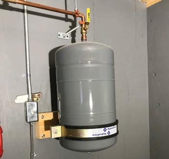
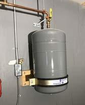
Detail 10. Don’t leave an expansion tank vulnerable to impact. Small expansion tanks that hang from ½-in. top con -
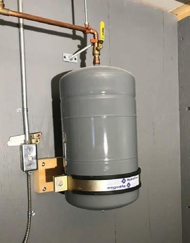
4
nections can be easily bent by accidental impact. Ask me how I know this… If the tank must be mounted in a vulnerable location use a strapping system to secure the shell to a solid surface, as shown in Figure 4 (above).
Expansion tanks perform a simple but very necessary function. Follow these details to keep them functioning as intended. <>

John Siegenthaler, P.E., is a mechanical engineering graduate of Rensselaer Polytechnic Institute and a licensed professional engineer. He has more than 35 years experience in designing modern hydronic heating systems. His latest book is Heating with Renewable Energy (see www.hydronicpros.com).
1. Modern Hydronic Heating, 3rd Ed., John Siegenthaler, Cengage Publishing 2012, ISBN -13: 978-1-4283-3515-8
2. Heating with Renewable Energy, John Siegenthaler, Cengage Publishing 2017, ISBN -13: 978-1-2850-7560-0

This case study illustrates the impact architectural changes can have on mechanical system design.
BY ROBERT BEAN
Over my career I have been fortunate to work with some great clients and design and construction teams where the relationship was not just about completing a successful project but also about education—that being the exchange of knowledge that one earns from challenging events. Any seasoned practitioners will tell you it is ‘project pain’ that provides the experience and any pleasure after that is just a bonus. This case study is an example of a ter-
rific client, an excellent team and a project with some interesting moments.
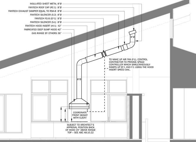
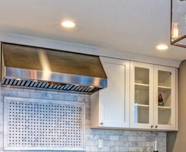
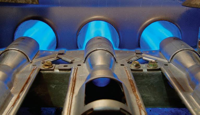
The 7,800 sq.ft. home (Figure 1) borders between climate zone 6 and 7 with a winter design temperature of -35F (-37C) and summer at 85F (30C). It had several common indoor environment quality (IEQ) challenges, initially including a six-burner gas range, a 6-foot (1.8m) gas fireplace in a great room that had a bank of windows extending 20 feet (6m) up from the floor, a gym and an attached garage that was big enough that it initially required CO monitoring. Several rogue zones had thermal comfort concerns due to large windowto-wall ratios and air quality concerns due to the attached garage, fireplace
and kitchen range combined with the required large exhaust hood. The latter adding a potential noise issue.
The five-person family reached out to us after an online search for healthy indoor environments introduced them to our website and services. After our introductory interview, project questionnaire and initial site meeting, it was clear our project values would work together.
We set out expectations and deliverables, which included consultation on the architecture, enclosure and HVAC design. Our thermal comfort and air quality targets were guided by ASHRAE Standard 55, and a mix between ASHRAE 62.2 and CSA F326.
We also conducted solar control and daylighting with several discussions on

external shading, window characteristics and performance.
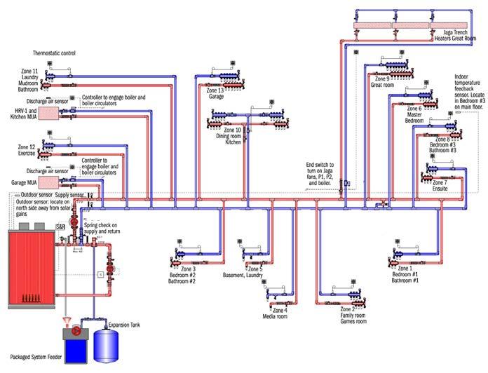
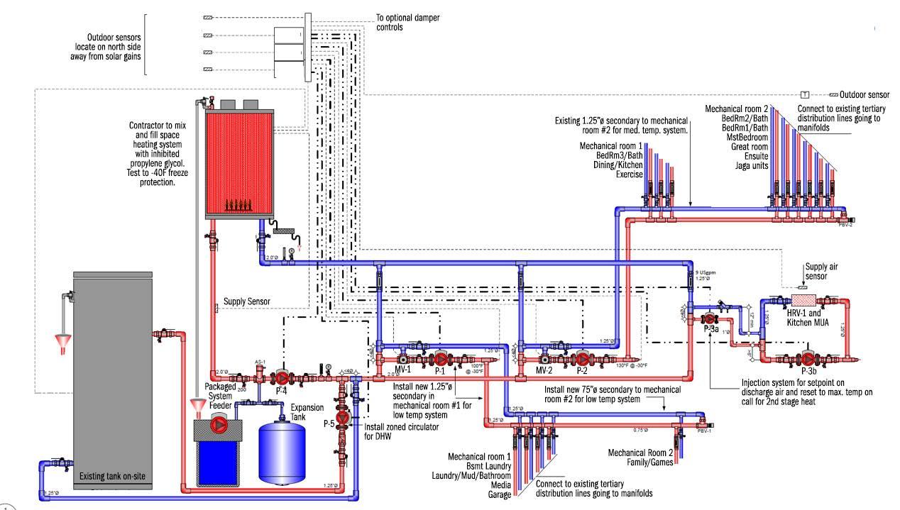
From these initial discussions and agreement on critical enclosure improvements, our load calculations resulted in a dead-simple single low-temperature hydronic heating system (Figure 2) with reset using only the boiler controls and with only one circulator for the system and non-electric thermostatic control valves for room control.
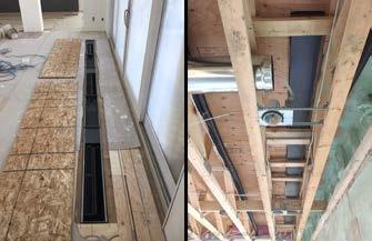
It does not get much easier for such a large home. The harmonized temperature was established by manipulating floor tube spacing where possible, increasing radiant surfaces in rogue zones using wall space under windows (Figure 3), adding a trench heater for the great room, and increasing the surface area of the makeup air coils. This approach is preferred over a multi-temperature system, which adds more costs for controls and circulators, commissioning complexity and future maintenance issues for the owner.
At least this was the plan until what was discovered after approval for construction drawings were issued. During a site visit, it became apparent that the specified exterior insulation and radiant walls had been omitted, and additional windows had been installed.
As any professional practitioner can attest, such deviations from a stamped design is not a minor event. We advised there would be heating and cooling load penalties on most zones requiring a complete system redesign.

After getting approval for the additional engineering fees, we developed design version 2 (Figure 4). The consequences from the revisions resulted in the very system we had tried to avoid initially. The new calculations revealed a need for more complicated systems with multiple temperatures, which meant electronic controls and more circulators and a redesign on the partially installed distribution piping system.
It also meant an increase in the heating plant and cooling equipment and
distribution piping. We did not do a postchange cost analysis, but I suspect between our fees, the increase in capital costs, including the service fees from
Continued on MH10
the installer, would have paid for a big part of the omitted insulation.
Indeed, any balance would have been quickly offset by lower operating costs relative to the now higher loads.
The client was entirely professional about the hick-up, as were the trades, which helped make the changes flow without any conflict.
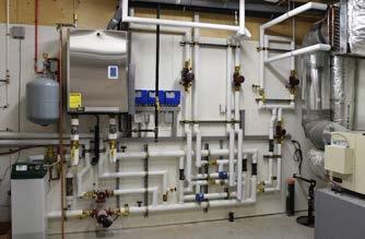
Ultimately the real consequence for the project is an increased load profile and more complex system. Fortunately, the final piping assembly was done the way I like them, plumb, parallel, level, and square (Figure 5 ).
Our ASHRAE Standard 55 assessment of several rooms, and specifically of the great room, showed potential for drafts, radiant asymmetry, and mean radiant temperature (MRT) issues due to the large bank of windows.
Our year-round solution, in addition to radiant floors, was to place a hydronic trench heater directly in front of the patio doors (Figure 6).
In the winter, this would provide a warm curtain of air to stop the down -
draft, warm the glass and improve the asymmetry. Also, a preheat coil on the HRV/kitchen exhaust make up air unit could be used for supplemental heat.
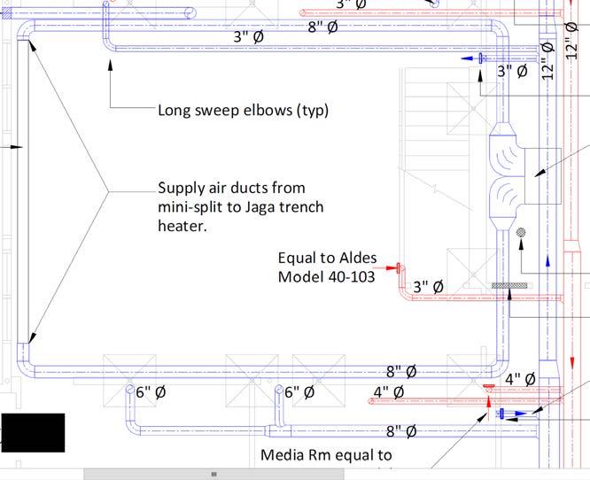
For cooling, we used a ducted minisplit and fed its cooled air into each end of the trench heater, and we used its linear fans to boost the airflow up the glass (Figure 7 ). This cooled the inside surface temperature of the glass, reducing the asymmetry and MRT issues.
In combination with elevated airspeeds from a large ceiling fan, the room fell within compliance with ASHRAE Standard 55.
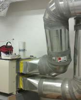
Next up was how to provide up to 800 cfm (378 l/s) of kitchen range exhaust with makeup air, and up to 400 cfm (189 l/s) of home ventilation air with a single air handler.
In either operation, the sound from
airflow had to be minimized. Our kitchen exhaust solution was an inline direct drive exhaust fan with silencers on the inlet and outlet. The fan was located about 20 ft (6m) away above the range in the attic space. A strategy I have used many times with excellent results (Figure 8).
The building ventilation was a multispeed HRV whose exhaust fan was disabled by controls when the kitchen exhaust fan was on (Figure 9). Thus, without exhaust flow, the HRV became a makeup air unit.
Preheating the air in both modes was a generously sized glycol coil. Home ventilation ducting was designed for low velocities from 200 fpm (1.0m/s) up to 500 fpm (2.5m/s) and kitchen exhaust from 1000 fpm (5.0 m/s) up to 2000 fpm (10m/s).
Continued on MH12

The control solution is proprietary, but I will take this opportunity to strongly suggest that manufacturers of both kitchen exhaust fans and HRV’s develop an integrated solution for speed matching their products and disabling the HRV exhaust fan.
Through the integrated design process, thermal comfort, lighting, sound, and in -
door air quality criteria should be first and foremost passive solutions.
Thus architecture, enclosure and interior design are the first solutions to indoor environmental quality challenges. These “three amigos’” when adequately designed simplify electrical and mechanical systems and their associated commissioning, maintenance, capital and operational costs.
Far too often energy conservation is ig-

nored, forcing designers to unnecessarily use the brute force of energy in the form of heat and electricity to solve IEQ problems. There is also a failure to use design solutions like harmonizing fluid temperatures to the lowest common denominator to enable higher system efficiencies.
In this case, the original intentions were good but were destroyed by what was thought to be an inconsequential decision.
As we have said before…in design –everything matters.
***
Considering the current pandemic there are no words to describe how comforting it is knowing our engineering philosophy of ‘designing for people’ has left behind indoor spaces that are serving our clients with excellent independent and dedicated air quality and thermal comfort systems. For the naysayers of days past – I told you so…there – I said it! <>
For more on ASHRAE Standard 55, interested practitioners can obtain for no charge a new book on Thermal Comfort Principles and Practical Applications in Residential Buildings. This project was funded in partnership with BC Housing and can be accessed through this link: www.linkedin.com/groups/13843486/

Robert Bean is director of www.healthyheating.com, and founder of Indoor Climate Consultants Inc.
He is a retired engineering technology professional (ASET and APEGA) who specialized in the design of indoor environments and high performance building systems.


The Brute FT® Combination Boiler and Water Heater utilizes the latest in fire tube technology to offer your customers:
• Exceptional Efficiency. The Brute FT®’s modulating technology automatically adjusts fuel usage to match heat demand – to help your customers save on heating utility bills compared to standard “on-off” boilers! ENERGY STAR® rated, 95% AFUE.
• Outstanding Performance with Higher Flow Rates (4.8 GPM at a 77°F rise). The Brute FT® Combi has a shell-and-tube domestic hot water heat exchanger that gives your customers unrestricted flow and better performance than brazed plate heat exchangers.
• Quicker Hot Water Delivery. The Brute FT® combines storage with on-demand hot water for faster performance.
• Compact Design. Easy to install and service, even in tight spaces.
• Excellent Flexibility. The Brute FT® is field convertible between natural gas & propane, is cascadable up to 20 units, and can be vented with PVC, CPVC, or polypropylene.
To learn more about the Brute FT® Combi, visit bradfordwhite.com
Drive to reduce greenhouse gases is putting pressure on fossil-fuel-fired mechanical equipment.
BY ROBERT WATERS
The push is on from many levels of government to go “low carbon”, reduce greenhouse gas (GHG) emissions and address climate change. The HVAC sector is part of this push and one result is that traditional oil and gas-fired heating equipment is under pressure. Governments would like to see this equipment become extinct. What does this mean for the hydronic industry and contractors?
There are several examples of recent government policies indicating that traditional fossil fuel heating equipment in Canada may be on the way out. Space and water heating equipment are certainly being targeted due to the fact that residential and commercial buildings account for 17% of total greenhouse gas emissions in Canada. Space heating represents 56 to 64% of the energy use in homes and buildings, and water heating represents 8 to 19% of the energy use.
The Pan-Canadian Framework on Clean Growth and Climate Change outlines the commitments of the federal, provincial and territorial governments to reduce greenhouse gas emissions and promote clean, low-carbon economic growth for Canadians. These governments have set aspirational goals for energy-using heating equipment in the building sector that reduces greenhouse gas emissions significantly.
To support the transition to a low-car-
bon economy, governments approved the “Market Transformation Road Map for Energy Efficient Equipment in the Building Sector” at the Energy and Mines Ministers’ Conference in August 2018. This plan sets short- and long-term goals for space and water heating equipment.
The short-term goal requires that by 2025 all fuel-burning technologies for space heating for sale in Canada must meet an energy performance of at least 90% (condensing technology).
The long-term goal states that by 2035 all space heating technologies for sale in Canada meet an energy performance of more than 100%. This goal would see the transition of the entire space and water heating market to heat pump technology or integrated gas absorption heat pump systems.
These ambitious goals still have a long way to go to become reality, however the writing seems to be on the wall … traditional fossil fuel boilers, water heaters and furnaces are under threat of being phased out.
The City of Vancouver is one jurisdiction that is taking greenhouse gas emission reduction very seriously. Vancouver’s “Renewable City Strategy” has set a longterm target to have all buildings in the city (including those already built) use only renewable energy by the year 2050. Vancouver has a head start on most jurisdictions around the world as its electricity supply is already close to 100% renewable. BC’s grid is over 97% renewable due to hydroelectric generation and therefore has very low GHG emissions. As a result, while electricity conservation remains important, the focus of the Vancouver plan is on reducing the demand for fossil fuel space heating and hot water heating. The plan is to transition these functions to renewable sources such as electricity and bio-gas.
In July 2016, Vancouver moved its plan forward by introducing their “Zero Emissions Building Plan” which requires the majority of new buildings in Vancouver to have no operational GHG
emissions by 2025, and all new buildings have no GHG emissions by 2030.
Under this plan Vancouver introduced the “Green Buildings Policy for Rezoning’s” in May 2017, which targeted new high-rise multi-unit residential buildings. The latest bylaw amendment from May 2020 will require all new residential buildings three storeys and under to install zero-emission space and water heating starting in January 1, 2022.
The next step is anticipated in 2025, when both new and replacement heating and hot water systems must be zero emissions. The city anticipates this shift towards zero emission space and water heating will be met with heat pumps.
Vancouver is predicting that air-to-water heat pumps are likely to be a common heating solution for new single-family homes, as over 90% of typical single-family homes built in 2019
were heated with hot water. Water heaters will need to be electric resistance or heat pump water heaters.
The City of Toronto's “TransformTO” plan includes a set of long-term low-carbon goals and strategies to reduce GHG emissions, improve health, grow the economy and improve social equity.
Toronto aims to achieve Net Zero builldings by 2050. The plan has targets for all new buildings to be built to produce near-zero GHG emissions by 2030. By 2050, all existing buildings will have been retrofitted to improve energy performance by an average of 40%. Toronto has not yet introduced any low-carbon equipment requirements.
There are immense challenges and barri-
ers to reach the goals set by these new policies. For low-carbon or zero emission equipment, the market transformation roadmap outlined by the Energy and Mines Ministers’ Conference outlines the “five A’s of market transformation”:
• Availability: Does the technology exist?
• Accessibility: Does the market have access to the technology?
• Awareness: Does the market know about the technology?
• Affordability: Is the technology affordable?
• Acceptance: Is the form, fit, and function of the technology acceptable? There are several examples of lowcarbon space and water heating equipment that are currently being utilized in the Canadian market. Space heating systems can utilize electric resistance heating systems such as baseboards, Continued on MH16


forced air furnaces and hydronic boilers. All of these products have been available and accessible for a long time, and offer affordability, public awareness and acceptance. The main issue that resistance heating has working against it is the high cost of electricity in many regions of Canada.
Heat pump options include both air and ground source (geothermal). Heat pumps are much more efficient than resistance electric, typically providing 2 to 4 times higher efficiencies. Air source and geothermal heat pumps are available to either provide heat to a forced air distribution system or to a hydronic heating system. Both air source and geothermal systems have high water temperature limitations, with neither type working very effectively above 140F.
Geothermal heat pumps provide the highest possible operating efficiency, with consistent year-round performance, but also have the highest installation cost due to the expense of adding vertical or horizontal ground loops.
Air source systems have good performance when outside temperatures are mild, however they can see a significant drop off in performance when the ambient air temperature drops much below -15C. Heat pumps have been around for many years, but the market for the different types has fluctuated based on performance issues (air source) and government subsidies (geothermal).
Air source heat pumps have seen a resurgence in recent years, especially in the Atlantic region. Heat pumps are widely accessible and generally have good market awareness, however barriers still exist with affordability (especially geothermal) and acceptance.
In their market transformation roadmap National Resources Canada (NRCan) identified a number of challenges and barriers to transitioning to low-carbon ground source, air source and gas heat pumps. These include technical barriers such as: the perfor-
mance of air source heat pumps at low ambient temperatures (as mentioned), a lack of standardized test procedures for rating the energy performance of airsource units, high cost for installation of geothermal, retrofit challenges that will add cost and require additional components and controls, variability of commercial building stock and the challenges in remote communities.
They also identified market barriers that include product availability and training requirements for designers, contractors and building owners. Governments envision gas absorption heat pumps playing a major role in the future for low-carbon heating systems, as they may offer a significant increase in performance beyond that of existing gas-fired heating systems. However, they still face barriers to availability, accessibility, awareness, affordability and acceptance because they are not yet commercialized in Canada.
Two big stumbling blocks to a full lowcarbon transformation across Canada are the affordability and availability of electricity supply.
While energy costs vary in different regions of Canada, the reality in most areas is that the cost of electricity is much higher than natural gas. Carbon taxes will gradually increase the cost of natural gas, with the federal carbon tax prices currently at $20/tonne, rising to $50/tonne by 2022.
Natural gas still remains abundant and inexpensive in Canada however, and even with the carbon tax added on will likely remain the preferred choice in most areas for years to come.
Natural gas is currently widely available and serves over 7 million customer locations and over two-thirds of Canadians. There are currently over 570,000 km of underground transmission pipes bringing natural gas across the country.
A transition to high levels of mandated electrification will require a costly expansion of Canada’s electrical infrastructure. Presently only 20% of our energy requirements are met by electricity.
With all of these challenges the transition to low-carbon equipment will likely hit speed bumps along the way. The economics alone will make it difficult to convince consumers to change from natural gas to more costly electricity.
Transitioning to heat pumps will require expensive retrofit costs and electrical service upgrades for many buildings. Finding space to add the heat pump outdoor condensing may be difficult for buildings with tight building lots. Added noise from the outdoor units is something customers will have to get used to.
The mechanical industry will have to transition as well, with new equipment and installation techniques to learn. These hurdles will require intensive marketing and information strategy from governments, utilities and the HVAC industry to get consumers on-side.
While the transition may appear difficult, the benefits of reducing GHG emissions cannot be overlooked. Phasing out millions of fossil fuel fired heating units is one of many actions required to enable Canada to reach its emission reduction targets. This transition should create a boost in economic activity, requiring skilled workers and create demand for new equipment.
This will certainly benefit the HVAC industry, and the reduction of GHG emissions will certainly benefit the planet. <>

Robert Waters provides training, education and support services to the hydronic industry. He has over 35-years’ experience in hydronic heating and solar water heating. He can be reached at solwatservices@gmail.com.


150% wider waterways - Wider pipes allows water to pass through the heat exchanger more effectively, with less risk of blockages.


• Onboard Wi-Fi provides remote control and monitoring

• Up to 11:1 modulation
• Up to 96% AFUE

• Heat only and combi versions


• Integrated ECM pump and diverter valve on all models
• Whisper quiet


• Small zone valve systems may not require primary/secondary piping


DEPENDABLE BY DESIGN.
A ll of our products feature NTI’s legendary combustion stability, durability and preformance.
Exploring the proper application, operation and commissioning of residential ECM circulators.
BY MIKE MILLER
Iabsolutely believe that the electronically commutated motor (ECM) circulator is as significant to this industry as the modulating condensing (ModCon) boiler was when it arrived and still is. Just knowing that the circulator has the ability to adjust the flow of the system to better match the current load condition is awe-inspiring.
The circulator, which has always been an important part of the hydronic system, now “dovetails” with the heating equipment to raise the overall system efficiency, and not just the reduction in wattage consumption (full speed comparison of approximately 50% when compared to a traditional PSC motor), but also the lower return temperatures, longer equipment run times—longer steadystate efficiency, and with the turn-down ability of Mod-Cons, being able to reach and maintain the “thermal equilibrium” for longer time periods.
I have seen results of ECM circulator trials for well over a decade and they have always passed scrutiny. In 2015 a colleague replaced a delta-P controlled system circulator with a ‘newer’ delta-T unit. He used the same model circulator as his condensing boiler primary circulator and both of them were operating at a fixed delta-T of 30F.
He reached design temperature twice that season (~11F). His typical watt consumption on the boiler circ went from a fixed 80 watts (spd. med.) to something typical of 11 watts. And the bigger deal, his boiler return temperature was at its
lowest average ever.
We know ECM circulators deliver efficiencies, but it’s important to understand how to properly apply and set the correct mode of operation.
Most current residential ECM products have multiple operating modes: fixed speed (FS), constant pressure (CP), proportional pressure (PP) and some have an additional “Automatic” mode (which is also a PP mode) and some use “Delta T” (the ultimate Auto mode), and all of them, if applied correctly, can result in the highest overall efficiency.
Fixed Speed (RPM) mode: (non-automatic) The fixed speed mode is appropriate when the application will not have changes in the operating points (varied hydraulic pressures down-stream of the circulator) like zone valves or actuators opening and closing. Examples of proper application of the fixed speed mode would include: single zone pumping, boiler circulator in a P/S piping configuration, DHW heat exchanger, pool or spa
heat exchanger, snow/ice melting etc. (see Figure 1)
Constant Pressure mode: (automatic) The constant pressure mode is suited for the traditional North American piping scheme; these are typically multiple zone systems using individual zone valves or actuators on a preassembled manifold with a “system” circulator. The distinguishing difference of this layout is the paralleled supply and returns that run to and from the “near boiler piping” header in the mechanical area. This has also been called a “Home-Run” configuration. (see Figure 2)
Proportional Pressure mode: (automatic) The proportional pressure mode is best suited for the “extended header” piping scheme. The distinctive difference of this layout is the supply and return piping is extended out in the building, and the branches/take-offs are out there as well. These multiple zone systems could be a mixture of different zone operating devices or terminal units such as: fan coils, fin-tube baseboard, cabinet unit heaters or simply several hydronic radi-
ant floor manifolds. All these heat emitters could be controlled by different devices: on/off zone valves, actuators, modulating valves, mixing valves or diverting valves. (see Figure 3, next page).
The primary benefit of ECM circulator technology is that it offers much more “controllability”. It allows complete control of the speed and direction of the circulators, and therefore complete, or more precise, control of the flow of hydronic systems.
The ECM also provides the capability to control the power consumption, and it allows the ability to know when something is wrong with the circ or motor. This information can be used to quickly assess a situation and make changes to the signal, its speed and its direction, or completely shut the motor off.
As previously discussed, I have looked at results from two particular different circulator input control methods; delta T (temperature differential) and delta P (pressure differential).
Delta P (∆P) controlled circs make their adjustments to the speed (rpm) based on what they feel. Things change in a multiple zone system “hydraulically” when zone valves close and open back up, or TRV’s squeeze close. So the mo -
tor feels these hydraulic changes within the system and can ramp down or back up depending on what is required at a given time. No special sensors or pressure transducers are required. Since hydraulic changes in the system can be felt almost instantly, the reaction time in a ∆P circ is very quick.
Delta T (∆T) controlled circs make their adjustments to the rpm based on what they measure. They look at feedback from two separate thermistors, one on the supply piping out to the system and the other on the return piping. When powered, these sensors constantly measure the temperatures and will ramp the circ’s motor down or up to maintain the “designed for” ∆T.
The ∆T is what you use in a flow rate (gallons per minute, GPM) calculation: GPM = Btuh / ∆T x 500; so to use a very important segment of this calculation to control the flow in a residential hydronic system can make sense for many applications. Since temperature changes in the system can take a little while to sense, the reaction time in a ∆T circ is a bit longer than a ∆P circ.
Fixed speed “non-automatic” mode is fairly straight forward as far as the piping
scheme goes so no additional explanation needed there. But a common question is, ‘Which “automatic” operating mode should the circulator be placed in; constant pressure (CP) or proportional pressure (PP)?
The answer relies on how the system is, or will be, piped.
When a system is piped with parallel supply and returns brought back to the boiler as illustrated in the constant pressure mode example (Figure 2), one of the zones will set the maximum pressure drop (PD) required (plus a little for the near boiler piping and incidentals). The system circ still needs to be able to achieve the pressure drop requirement of that single zone, the one that set the PD target.
When the other zones close in the system, the GPM can drop dramatically (due to the circ’s ECM responding to the hydraulic change) but the head requirement is still based on the zone that set the PD target.
CP mode will always try to maintain a “Fixed” desired head setting. For example, one model in the CP Mode has three fixed operating range settings: 5ft./hd, 10ft./hd and 15ft./hd. To select the right head setting requires some educated calculations/estimations. It’s always best to calculate the PD of the system so the correct setting can be used, but here’s a rule of thumb for generalized purposes: 5ft.= baseboard, 10ft.= typical radiant and 15ft.= fan coils or other high PD applications as long as the GPM requirement for any of them can be met.
Another point to understand, the circulator operating in CP mode will only slow down “automatically” if the system’s pressure drop from PVF (pipe valves and fittings) can induce enough resistance to maintain the particular head setting.
If you over estimate the PD of your system, let’s say you choose 15ft. head but the system will only impart 12ft., the circ will simply run out on its maximum rpm curve and it will not automatically
slow down. (It’s better to slightly underestimate/round down in the CP mode)
So as zone valves close in the system, the circulator’s EC motor senses that resistance change then adjusts the rpm of the motor to a lower speed, hence the flow decreases but the motor speed will work to maintain the desired head setting.
PP mode is similar to the CP mode however it uses a “proportional” reset adjustment. As the PD in the system increases due to hydraulic changes (valves closing etc.) the EC motor senses those changes just as it did in the CP mode and will lower its speed but with a slight difference, it moves the head setting downward on a slight decline or pitch from what it was at max rpm.
The manufacturer sets up control logic in the circ’s microprocessor to a predetermined percentage of decline slope. For example, one model of ECM circulator in PP mode has three operating ranges: low, med or high. That means from a maximum head/GPM point on any of the three settings the performance range slopes back at 58% as it approaches ‘0’ GPM. The operating range slightly declines so that when the circulator senses hydraulic resistances it slows down and lets the head reduce along with the GPM.
Now with what I’ve covered in regards to CP and PP control options, let’s go back and think about a potential negative scenario. Picture a typical North American parallel S&R piped system, zoned with zone valves served with an ECM system circulator, similar to Figure 2, but that circ is set to run in a PP mode.
Under conditions approaching outdoor design temperature, this configuration may not give you the GPM and head required for a specific zone calling on its own. Recall that in PP mode the circ motor is working to lower its head based on a reduction in GPM requirement.
I’ve heard of people being called out for a “low or no heat call” when it was at or approaching design temperature. They’ve said the ∆T across certain zones was
stretched way out and the quick fix was to change from PP to either CP or FS.
Delta T controlled system circulators are the easiest to discuss. The sensors, if located and installed correctly will read the system’s temperature differential in “real-time” and adjust the motor speed accordingly. It will keep the ∆T at the “designed for” condition depending on the model, from 5F to 50F in one degree increments, typical settings of 20 to 30. (see Figure 4)
My hope is that the information in this article helps you better understand the
application, operation and commissioning of residential ECM circulators. As you apply this knowledge we all win because our collective “systems” get better and more efficient.
A special thank you to Rick Mayo, Taco Comfort Solutions products and applications instructor, Western Region, for his enormous contribution to making this article happen. <>

Mike Miller is director of sales, commercial building services, Canada with Taco Inc. hydronicsmike@ tacocomfort.com


From heating controls to mixing valves, Resideo offers a full range of Honeywell Home hydronic product solutions. Find Hydronic Zoning Panels, Pro Press Zone Valves, T6 Pro Hydronic thermostats and more — all in one location.
Our reputation is based on providing you with products to provide homeowners with solutions. Our products have proven to be must-stock standards, engineered for accuracy, safety and reliability — and easy installation.
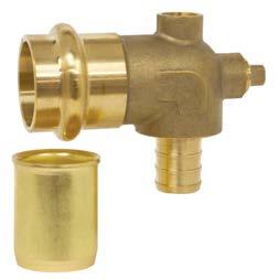
Webstone has expanded its line of transition products including Press × PEX reducing fittings, baseboard elbow and dual-vent elbow for use with a choice of 1/8-in. NPT vents. The dualvent design ensures an upright vent port is accessible. Ideal for boiler risers or baseboard radiator installations, each elbow includes a brass stiffener for copper finned tube press connections. Products are lead free and available for F1960 or F1807 PEX. webstonevalves.com/PEX
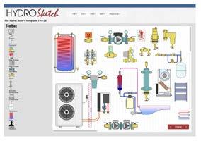
HydroSketch, a cloud-based software tool for quickly creating piping and electrical schematics for hydronic heating and cooling systems has introduced several enhancements. Developed by Appropriate Designs, the tool now has over 50 new component symbols for devices such as magnetic separators, air-to-water heat pumps and specialized buffer tanks. A growing library of “templates” also serve as starting points for basic hydronic schematics. A free 30-day trial is available. hydrosketch.com
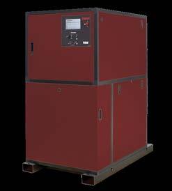
The RBI Torus commercial water tube condensing boilers and water heaters come in sizes from 1250 - 4000 MBH. Torus Boilers are up to 97.5% AHRI Certified efficient. Torus units feature a 5:1 turndown. The heat exchanger is made from 316L stainless steel and manufactured through tube hydroforming. The 4-pass design works with a multi-channel manifold and increased tube diameters resulting in ultra-high efficiency with very low pressure drop. rbiwaterheaters.com
A new addition to Calefactio’s hydraulic separators product range is the 2-Zone Calbalance. Hydraulic separators isolate primary circuits (boiler) from secondary circuits (application/heat transmitters). The 2-Zone Calbalance allows the connection of two zones directly. The unit is equipped with the Calvent automatic air vent. Housed in carbonized steel, it's provided with a wall bracket. Maximum operating pressure is 150 psi, and the maximum. operating temperature is 100C. calefactio.com
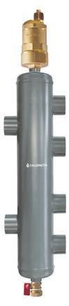
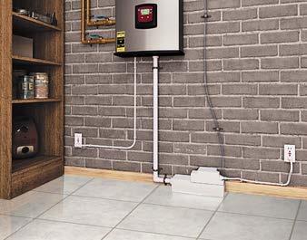
SFA SANIFLO Canada has introduced Sanicondens Best Flat, a low-profile condensate pump with a 0.9-gallon tank capacity and capability to serve multiple mechanical systems, up to a total of 500,000 Btu/hr. The 12-lb. unit combines a condensate pump with a pH-neutralizing pellet tray and can be installed on a level floor or wallmounted. The unit can discharge condensate 15 feet vertically and 150 feet horizontally. saniflo.ca
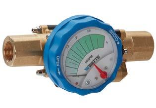
The iDROSET CSD series of static balancing valves from Watts offer contractors speed and ease when balancing a hydronic system. Its patented flow measuring technology allows users to set and read flow without additional tools. The valve’s gauge continuously indicates flow without the need to actuate a bypass circuit. A twist of the hand wheel sets flow and can be locked when the desired rate is set. watts.com

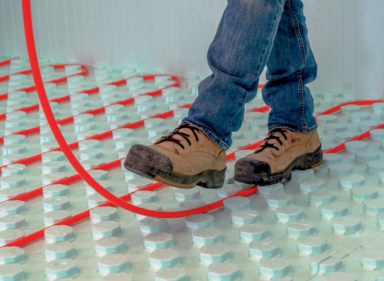
HYDROFOAM® IS THE IDEAL RADIANT FLOOR INSULATION PRODUCT FOR RESIDENTIAL AND COMMERCIAL CONSTRUCTION PROJECTS.
The floor of a building is often the most ignored surface when it comes to insulation. The floor, when insulated with HYDROFOAM, completes the building envelope and increases comfort and energy efficiency.
HYDROFOAM maximizes radiant floor heating by ensuring the heat is dispersed evenly throughout the entire floor area, providing building occupants with a comfortable living and working environment.
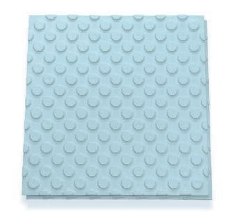
Controlling a renewable heat source combined with an auxiliary heat source.
BY JOHN SIEGENTHALER
Over the last 40 years I’ve had the opportunity to work with several types of renewable energy heat sources including solar thermal collectors, cordwood boilers, wood pellet boilers and heat pumps. They can all be integrated with hydronic heating distribution systems.
I’ve also worked with systems that took advantage of timeof-use electrical rates. or “off-peak” rates. During specific times of day, usually at night, and sometimes specific dates (e.g., weekday, weekend, holiday, etc.) the cost of purchasing electricity from the local utility is deeply discounted. Utilities do this to help manage peak demand by incentivizing the purchase of electricity at times of low demand.
So what do renewable energy heat sources and time-of-use electrical rates have in common? The answer is that systems using these energy sources almost always require significant thermal storage. For hydronic applications that storage consists of a large insulated tank filled with water.
Thermal storage tanks can be categorized as unpressurized and pressurized. Unpressurized thermal storage tanks must be vented to the atmosphere, usually through a small opening. This ensures that the pressure at the water’s upper surface cannot increase.
These tanks usually consist of an open-top insulated structural shell that’s assembled on site. A flexible liner made of EPDM rubber or polypropylene is placed into this shell, similar to how a trash bag fits into a trash can. The liner contains the water. An insulated lid goes over the top. Piping penetrations are usually made just above the highest water level in the tank.
A pressurized thermal storage tank, such as the 350-gallon tank shown in Figure 1, are usually constructed of steel. They can be insulated using several types of materials. That insulation is usually installed after the tank has been piped and all connections to the tank have been pressure tested.
Most mechanical codes require pressurized tanks larger than 119 US gallons to be ASME certified. This process involves traceable materials and physical inspections during fabrication. It adds assurance that the tank is well built and safe, when applied within the certification limits. It also adds significant cost to the units.
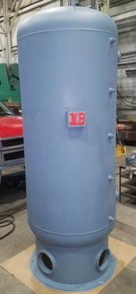
Systems using a thermal storage tank heated by a renewable source or off-peak electricity usually have an auxiliary heat source. In retrofit applications that auxiliary heat source is often an existing boiler. In new systems it could also be a boiler or a heat pump.
The control concept is to use heat from thermal storage whenever possible, and only use the auxiliary heat source when necessary to ensure the building remains comfortable. Heat is transferred from thermal storage into a heating distribution system as needed. Figure 2 shows a simple way to do this using a pair of closely spaced tees that provide hydraulic separation between the tank circulator (P2 , bottom right) and the distribution circulator (P3, top left).
Circulator (P2) in Figure 2 could be controlled as an on/off device, or as a variable speed injection pump. The latter allows accurate control of the water temperature sent to the space heating load. It also allows for outdoor reset of that supply water temperature.
Figure 3 (next page) shows how an auxiliary heat source would be integrated into this piping arrangement. Another set of closely spaced tees connects the auxiliary heat source to the distribution system. These tees provide hydraulic separation between circulator (P4) and the distribution circulator (P3). The auxiliary heat source also connects “downstream” of the thermal storage tank. This allows the coolest water in the system, that returning from the load, to flow into the lower tank connection. This enables the renewable energy heat source to operate at the lowest temperatures the system can provide. Lower water temperature operation increases the efficiency of most renewable energy heat sources.
The auxiliary heat source is only turned on when there is a demand from the space heating load, and when the temperature
of the water supplied to the load drops slightly below the minimum value necessary to maintain the heating load, as determined by an outdoor reset controller.
In systems with this configuration (e.g., thermal storage heated by a renewable heat source, along with an auxiliary heat source) it’s important not to allow heat produced by the auxiliary heat source to inadvertently enter the thermal storage tank.
Doing so would allow high grade energy such as gas, propane, fuel oil or electricity to be converted to lower grade energy (e.g., heat) before that energy is needed by the load. Heat is much harder to store compared to keeping energy in high grade form until needed.
The key to preventing inadvertent transfer of heat produced by the auxiliary heat source into thermal storage is by comparing the temperature of the water returning from the distribution system to that at the upper header of the thermal storage tank.
As long as the temperature at the upper tank header is a few degrees higher than the temperature of water returning from the distribution system, the thermal storage tank, or the renewable heat source that supplies it, can make a positive energy contribution to the space heating load. This control
Continued on MH26


September 22nd at 3:00 EST
Anticipated length: 50 minutes with 10 minutes for Q&A
Why air-to-water heat pumps are a market opportunity for hydronic professionals.
There’s a world wide trend underway that will undoubtedly affect the future of North American hydronics technology. That trend is away from fossilfueled boilers and toward electrically powered heat pumps. This trend presents a significant opportunity for hydronic pros that are ready to take advantage of it using modern air-to-water heat pump systems.
This webinar will introduce the basics of air-to-water heat pumps, describe why they will be a new niche for hydronic professionals, and show some basic system configurations. Attendees will see how their current knowledge and skills in crafting modern hydronic systems can be leveraged around this new heating / cooling source.
• Understand the basic operation & performance of air-to-water heat pumps
• Grasp global trends that will increase this market niche
• Understand the importance of low water temperatures in air-to-water heat pump systems
• Learn how to configure a basic system for heating and cooling
Presented by

tem. If the temperature at sensor (S3) subsequently drops to within 3-degrees F of the temperature at sensor (S4), circulator (P2) is turned off. The on/off temperature differentials of 5F and 3F are only suggested values. To minimize sensing error it’s best to use identical mounting techniques for both sensors.
Figure 4 shows the simple wiring needed to combine the functions of the outdoor reset controller with the differential temperature controller.
For the wiring shown, the controllers are turned on only when there is a demand for heat from the load. Both are assumed to be powered by 24 VAC.
When the normally open contact in the differential temperature controller closes it passes line voltage to operate circulator (P2). When the normally open contact in the outdoor reset controller closes it signals the auxiliary heat source to operate. That heat source is shown as being supplied from a separate electrical source. Circulator (P4) is powered through that same electrical source and operates whenever the auxiliary heat source is on.
The controllers shown are readily available and are relatively inexpensive. The control functions they provide are well established over several decades. The combined functionality of these two controllers provides a simple and repeatable way to manage heat input to a space heating distribution system from both a renewable heat source, (or heat stored from off-peak electricity), and an auxiliary heat source. <>
function is easily handled using a differential temperature controller.
Figure 3 shows a differential temperature controller installed to compare the temperature at the return side of the distribution system (S4) to the temperature at the upper tank header (S3). Circulator (P2) is only allowed to start if
the temperature at sensor (S3) is at least 5-degrees F above the temperature at sensor (S4).
This prevents heat generated by the auxiliary heat source from being inadvertently sent into thermal storage. It also prevents flow from what might be cool thermal storage into the distribution sys-

John Siegenthaler, P.E., is a mechanical engineering graduate of Rensselaer Polytechnic Institute and a licensed professional engineer. His latest book is Heating with Renewable Energy (see hydronicpros.com).

Fits all of our most popular products
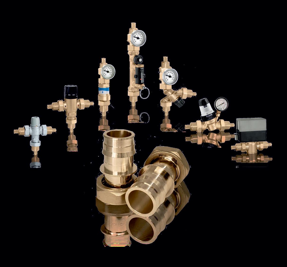
•Low-lead, dezincification resistant brass alloy for durability.
•Union fittings for fast and easy installation and service.
•Meets the requirements of ASTM F1960 for cold expansion fittings.
Components for today's modern hydronic systems

Heating & Cooling


Viessman is one of the most prefered and trusted brands in hydronic heating solutions in Canada for 40 years. Whether your project is a new home, commercial residence, or retrofit we offer heating solutions supported with digital tools to provide peace of mind at your fingertips:
• Program, remotely monitor & control your boiler using ViCare App
• Free expert advice when you request a heating system consultation online
• Extended 5 year parts and labour warranty for residential gas-fired condensing boilers up to 300 MBH input*

• DISTRIBUTORS • WHOLESALERS
Wolseley Canada is shifting its organizational structure from three operating regions to two, and has announced the following two promotions: .
Sébastien Laforge is now vice president, Eastern Canada and will oversee the Eastern plumbing and HVAC business, including Atlantic Canada, Quebec and Ontario, and the day-today operations of the industrial business in the region. He will be based in Laval, Que.
Chris Choquette is now vice president, Western Canada overseeing the Western plumbing and HVAC business, AMRE and the day-to-day operations of the industrial business in the region. He will be based in Burbaby, B.C.
Laforge and Choquette are members of Wolseley Canada’s executive management team, reporting directly to Kevin Fancey, president, Wolseley Canada.
Previously general manager, Western Canada plumbing and HVAC business, Choquette joined Wolseley in 2019 as senior director, B.C., plumbing and HVAC business. Prior to that he was the general manager business solutions at Ledcor Technical Services and held leadership positions at AcklandsGrainger Inc.
Laforge joined the organization as director, finance in 2007, where he managed financial responsibility for the eastern region of the business. In his most recent role as general manager, Quebec Plumbing and HVAC, he led and oversaw significant change and growth in the region.
Navien, Inc. has received the 2020 ENERGY STAR Canada Award for Manufacturer of the Year in the HVAC category. The annual Awards recognize manufacturers that have demonstrated excellence in developing and promoting energy-efficient products to the Canadian market.
The award was presented by Seamus O'Regan, Minister of Natural Resources, who said: “ENERGY STAR Canada winners are building a sustainable, energy-efficient and resilient future. By reducing pollution, lowering bills and creating jobs, Navien is helping Canada shine.”
Tool and technology maker
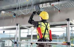
Hilti has announced the development of its EXO-01 wearable exoskeleton, a new human augmentation device designed to help commercial contractors and tradesman tackle health and safety issues and labour shortage challenges.
The wearable system helps reduce strain and fatigue for both experienced and novice users.
The product is Hilti’s first entry into exoskeletons for the construction industry, and development is initially focused on overhead and shoulder-height-and-above applications because this motion is physically intensive and fatiguing.
To develop the EXO-O1, Hilti partnered with Ottobock, a global leader in prosthetics, orthotics and exoskeletons that help people increase and retain their physical independence. Hilti is currently in real-world jobsite testing and will be bringing the exoskeleton to the market later this year.
The machinery is one part of the company’s solution. Hilti also plans to offer implementation, training and support services on site for Hilti’s customers and their teams. hilti.com
FortisBC, a utility serving over 1 million customers in B.C., is identifying six residential and four small commercial properties to test heat pump units from ThermoLift, a U.S.-based heat pump manufacturer.
The heat pumps, used for heating, cooling and hot water, have proven to be over 100% efficient, lowering energy costs by 30 to 50% and worked when outdoor temperatures dropped to -25C.
The utility launched its search for test properties in March and has completed 18 virtual home assessments over video calling and has identified residential candidates to move forward in the next stage of the pilot program.
FortisBC expects to install and begin testing the units later this year and early in 2021. In exchange for the heat pumps, participating property owners will allow the unit to be monitored and provide regular feedback for one year.
This information will help FortisBC better understand how these units operate on a day-to-day basis in a real world setting and determine if they meet the requirements for a fullscale energy efficiency rebate program. fortisbc.com/letsgo tm-lift.com
Past winners of the award in the HVAC category include: Venmar Ventilation (2019), ecobee (2018), Rheem Canada (2017), and LG Electronics (2016). Continued

Water technology company Grundfos will host a Virtual Walk for Water on Sept. 26 and 27, 2020 marking the company’s 10th annual walk in support of the fight against the global water crisis.
The Walk for Water is fundraising event held for Water Mission, a non-profit engineering organization that designs, builds and implements sustainable safe water solutions around the world. Participants walk 3.5 miles (5.6 km), the average distance that millions of women and children make each day to retrieve water that is often contaminated.
The Grundfos Virtual Walk for Water Kick-Off will be broadcast on Sept. 25, 2020 on global platforms including: LinkedIn, Facebook and YouTube. events.watermission.org/Grundfos Walk20
Enginuity Power Systems has acquired Detroit-based engine builder Katech as part of a strategy to speed the commercialization of its micro-Combined Heat and Power (mCHP) product, E1.
E1 replaces a standard water heater with a fully integrated system that provides a home with electric power and space and water heating requirements.
At the heart of E1 is a small internal combustion engine and. Katech is working on the latest generation, enginuitypowersystems.com
>> Masco Canada has announced a new partnership with Montrealbased Les Entreprises Roland Lajoie (Lajoie), and as of July 1 Lajoie now represents all of Masco Canada’s brands in Quebec. mascocanada.com lajoie.co
>> Centrotherm Eco Systems has launched Air Excellent, an air management system designed to improve IAQ in conjunction with an ERV/HRV system, to the Canadian market ahead of the rest of North America. The. Canadian representation includes: Barclay Sales (B.C. and Alta.); Equipco Ltd. (Sask., Man., Ont.); Lambert & Bégin Inc. (Que.); and Harris Atlantic Sales (NB, NS, PEI, Nfld.). airexcellent.ca


Noble recently promoted Rita Woodley to regional manager for the Greater Toronto Area (GTA). Woodley moves into this role from her previous position as GTA sales manager. With Noble since 2015, she has more than 25 years of experience in the plumbing and HVAC/hydronics industry and now will be responsible for enabling synergies between the sales teams and branch network to increase Noble’s position in the GTA. Darren Ince has taken on the role of regional manager for North East Ontario (NEO) at Noble. Ince has held several sales positions since joining Noble in 2003, including regional manager for the GTA. In his new role, he will be responsible for providing leadership, guidance and building the future landscape for Noble’s NEO region. The company has also promoted Stan Liberty to area manager for Northern Ontario. Liberty joined Noble in 2010 and most recently held the position of Barrie branch manager. In this new role, he will be responsible for expanding Noble’s branch network and overall footprint in Northern Ontario which is served by branches in Barrie and Gravenhurst today and a new Collingwood location opening this Fall.


ager, commercial sales training, and Karen Fox has been promoted to national showroom sales manager.

Wolseley announced the retirement of Akbar Makalai effective July 3, 2020. Makalai had over 40 years of experience in the industry and was a member of the Wolseley Canada leadership team since 2001. In 2017, he was the recipient of the Canadian Institute of Plumbing and Heating’s (CIPH) Lifetime Service Award. He held several roles with Wolseley Canada including vice president, plumbing and HVAC/R; general manager, British Columbia; and vice president, Western Canada plumbing and waterworks. Most recently he was vice president, vendor relations.
HRAI has named Lauralei Heggie to the role of business development director. Heggie brings more than 20 years of experience in leading revenue growth initiatives. Most recently she operated her own consulting company and has been consulting on specific projects with the HRAI. She previously held several progressive roles at Star Media Group.


Oatey has promoted Patrick Aquino to vice president of sales, wholesale plumbing. Aquino joined Oatey nearly five years ago as northeast regional sales manager, and most recently, was director of rough plumbing and commercial sales. With more than 15 years of experience in sales and business development, he will lead Oatey’s regional sales managers, commercial sales team and showroom sales team. The company has also promoted Adrien Scherer to manager, commercial healthcare sales, and John Waters to technical specialist, commercial sales. Scherer joined Oatey over three years ago and will now be developing relationships across the healthcare industry. Waters joined Keeney Manufacturing, which Oatey acquired late last year, more than three years ago, and in his new role will support commercial sales specification work within the engineering community. Oatey has promoted Dalithia Smith to vice president and Chief Human Resources Officer. Joining Oatey over two years ago as vice president, in her new role Smith will continue to lead all HR functions at Oatey and take responsibility for environmental, health, safety and security as well as diversity, equity and inclusion at the company. Darryl Jones is now serving as man -

When domestic water pressure becomes an issue, you have to determine: is it the pressure or the flow? BY STEVE GOLDIE
There is nothing quite like a worldwide pandemic to make you appreciate the simple pleasures of life. When life slows down, as it has for so many of us, we are able to notice those things we may have taken for granted during the frantic pace of so called “normal” life. The smell of coffee brewing in the morning, the sound of a child laughing, crisp clean sheets on a newly made bed; these are the kinds of simple pleasures that can sustain us amid the doom and gloom of uncertain times.
One of my favourite simple pleasures has always been a good long hot shower. Whether it is after a long day of work or a longer night of indulging in too much wine and too little sleep, there is nothing quite like a nice hot shower to rejuvenate and restore us to some semblance of humanity. Besides the hot water, the other essential element to a satisfying
shower is good water pressure, and the lack of good pressure is one of the most common complaints we hear about in the plumbing industry.
A typical residential plumbing system is designed to operate at between 40 and 70 pounds per square inch (psi) of pressure. In a municipally delivered system, water pressure is maintained through a series of pumping stations, elevated water reservoirs and water towers. Every 28 inches of elevation (water column) provides one psi of pressure, which calculates to just over 64 psi at the bottom of a 150-foot water tower.
Water pressure at any individual home or business is determined by its proximity to the pumping station and or the water tower or reservoir serving it. For a residence that is on a private well, water pressure is maintained via the well pump, usually in conjunction
with a pre-charged pressure tank.
When your customer is not getting enough water at the showerhead (or heads) the finger is always pointed at the water pressure, or lack of it, being the cause of the problem. However it may appear, poor water pressure is not always the culprit. The showerhead needs two things to perform effectively, it needs sufficient water pressure and it needs sufficient water flow to maintain that pressure.
Although both problems result in the same symptom, the solution depends on properly identifying the actual cause; is it insufficient flow or insufficient pressure?
Verifying the static pressure when all taps are turned off is as simple as attaching a pressure gauge at any point in the system. Gauges that attach to the hose connection are perfectly
suited to this application. Most well systems should have gauges already installed making verifying the pressure even simpler. If the static pressure is lower than 40 psi then the problem is indeed a low pressure problem.
Booster pumps are available from multiple manufacturers in various sizes, and if a simple boost of pressure is all that is needed, your local wholesaler should be able to help find one that is right for your application.
To size one properly you need to know what the required boost is, for example from 35 psi to 60 psi, as well as how much flow is required in gallons per minute (gpm). Most shower fixture manufacturers should publish the flowrates of their showerheads, so this will help you determine the gpm required. Booster pumps are well suited to take advantage of the variable frequency drive (VFD) motors that are becoming more and more common in recent
years. I would always recommend choosing the VFD option due to the vastly improved efficiency, quiet operation and very reliable results.
“Failing to correctly diagnose the cause of the problem can result in spending money and seeing no results.”
If the pressure was always culprit, the solution would always be the same; install a properly sized pump, adjust the pressure switch, and listen as everyone is singing in the shower. However, as I mentioned, pressure problems are very often not a pressure issue at all but rather a result of inadequate flow. Let’s go back to our pressure gauge.
When we check the pressure with all the taps turned off everything looks good. Now, have a look when one or two taps or fixtures are turned on. If the pressure drops dramatically, then the system piping is not able to supply sufficient flow to maintain adequate pressure.
The water service coming into the building may be undersized, or in an older building scale or corrosion may have built up restricting the flow. The same may be true of the distribution piping within the building; it may be undersized or obstructed. Providing the correct solution requires identifying where the deficiencies are located. Failing to correctly diagnose the cause of the problem can result in spending money and seeing no results.
Upgrading the incoming water service may be the best or most obvious solution. This likely requires trenching or torpedoing a new line in from the Continued on p48
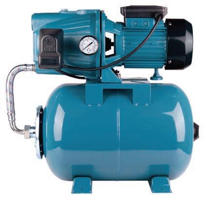
municipal service. If this option is not possible or too costly, a pressure pump system can be installed. These are very similar to those installed on private well systems, with a reservoir tank taking the place of the well (or lake).
Private well and pump systems include: the well (the water source), piping from the well to the building, a water pump, and a pressure tank to which building water supply plumbing is connected.
When water is turned on at a fixture, compressed air in the water pressure tank pushes water out into the buildings water supply piping and to its plumbing fixtures. The reservoir tank is not the same thing as the pressure tank, the pump cannot pull water through the service any faster than the service can already provide. The reservoir tank provides a ready supply of water for the pump to pull from, enabling the requisite boost in pressure and flow.
Too many times I have seen where a homeowner has paid good money for a pressure pump system only to have the same problem that existed before the system was installed. The reason; no reservoir tank was installed.
The key factor is providing enough flow to sustain the required pressure at the fixture. If you have a shower system that requires six gpm and the water service or well is only providing four gpm, there is no pump in existence that can fix this problem by itself.
I know that many contractors do great work and properly size their systems. Shower systems today are very different from those of just a few years ago, multi spray and large rainfall showerheads now seem to be the norm rather than the exception.
Dealing with pressure and flow problems in an older house is understandable, but having to live with it in a brand new home is never acceptable. Main supply lines and risers, both hot and cold, should be ¾-in. minimum, with ½-in. lines only used as feeders to individual fixtures.
Homerun systems are more popular than ever and offer very good results. A ¾-in. pipe has almost 50% more circumference and nearly 132% greater cross-sectional area than a half inch pipe. This means much more water, less resistance and, therefore, much more pressure and flow at the fixtures.
The difference in cost between doing it right or not is but a proverbial drop in the bucket, and few homeowners would hesitate to pay if they understood the benefits. It is a small price to pay for the ability to shower unencumbered without worry about who is flushing what.
Properly designed, installed and maintained plumbing systems are essential to our domestic happiness and bliss. It may just be that the simple pleasures, such as good hot showers, may just be the things that keep us all sane and prevent us from descending into full blown chaos. Who knew the humble plumber was responsible for keeping our civilization civilized? <>

Steve Goldie learned his trade from his father while working as a plumber in the family business. After 21 years in the field, he joined the wholesale side of the business in 2002. His expertise is frequently called on to troubleshoot systems and advise contractors. He can be reached at sgoldie@nextsupply.ca.

Understanding the added benefits that EM motors bring to the refrigeration industry.
BY DAVE DEMMA
Who doesn’t remember their first car? It’s one of those landmark decisions, and a rite of passage of sorts. With a single purchase, one goes from being dependent on the availability of your parent’s cars to get around, to complete freedom. This was brought to mind as one of my sons purchased a car last week; his first set of wheels. To say he was excited would be a complete understatement. After the excitement of the first few hours wore off, the reality of acquiring insurance, paying for his own gas and maintenance, and of course registering his car hit him.
The day after he made his purchase, in anticipation of talking to insurance brokers, he asked me this question:
“Where do I find the car’s VIN number”?
Attempting to be the annoying/instructive parent, I responded with “You mean the Vehicle Identification Number Number”?
I got a “deer in the headlight” look, then a “What”?
To help him understand, I shared that VIN stands for Vehicle Identification Number. One either refers to it as the VIN, or the Vehicle Identification Number. It’s a redundancy to add the word “Number” after saying VIN.
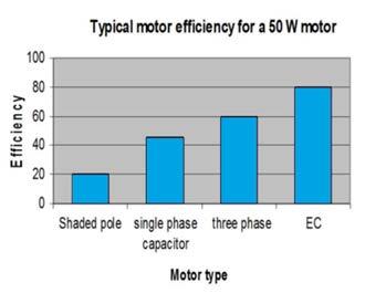
What is the point of this story?
Well, to further beat a dead horse, I’m reminded of the movie Mickey Blue Eyes. Certainly not an Oscar caliber movie, but as a light hearted romantic comedy, it provided a few good laughs.
In it, Michael Felgate (played by Hugh Grant) is an English auctioneer who manages a prestigious auction house. He’s madly in love with his American girlfriend, Gina Vitale (played by Jeanne Tripplehorn).
Early in the movie, Michael picks up Gina to take her to dinner. Knowing that her father owns a restaurant, he asks “Tell me what his restaurant is called, so I can sneak in, in a beard.”
Gina: “It’s called The La Trattoria”
Michael: “You mean, La Trattoria”.
Gina: “No”
Michael: “The La Trattoria means
The The Trattoria”.
Gina: “I know”
Michael: “Interesting”
At this point, you…the reader…are probably really starting to wonder where this is going.
Well…you see.
Why don’t we first locate the VIN Number on my son’s car, head to The La Trattoria, and over lunch we can discuss ECM Motors … Arggggg.
Since ECM stands for electrically commutated motor, there is no need to refer to them as ECM Motors, yet another redundancy I hear all of the time. Now, EC Motor is perfectly acceptable. OK, enough, I’m climbing down from my linguistics soap box now.
The EC motor is made up of two components; the motor and a motor control module.
The motor portion of the ECM is a three phase DC motor, but conventional systems do not have a DC power supply to power them. It is the motor control module which provides the necessary DC voltage. AC voltage is supplied to the motor control module which then converts it to three phase DC voltage. The motor is equipped with a permanent magnet rotor, which contributes to its efficiency.
While typical DC motors are supplied with brushes to provide the commutation (alternating the cycle), EC motors are brushless, the commutation is done electrically with the controller. The controller then sequentially energizes the three motor phases at the appropriate time for optimum operation. Additionally, the controller has the abil -
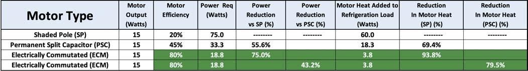
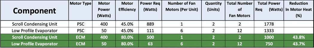
ity to modulate speed.
There are several benefits in using EC motors:
• Greater efficiency
• Quieter
• Variable speed
• Reduced motor heat (reducing the heat load)
The chart on the previous page (Figure 1) illustrates the differences in efficiency between the common motors used in refrigeration evaporators: shaded pole, single phase capacitor (SPC), three phase and EC.
Using those efficiencies, one can calculate the power requirement for a given size motor. A motor that is operating at 20% efficiency will require 5 watts of power for every watt of motor output (1 ÷ 20%).
The additional 4 watts (per watt of motor output) is transformed into heat energy. If this is an evaporator fan motor, that heat is transferred to the refrigerated space, and this must be accounted for when determining the refrigeration heat load, which is used to size the equipment.
In addition to potentially requiring equipment with higher capacity, this extra heat load will require that the refrigeration equipment operate longer to remove the heat.
The Motor Type chart (Figure 2, bottom left) quantifies the power requirement and heat added to the refrigerated space for the following motor types: (1) shaded pole (SP), (2) permanent split capacitor (PSC), and (3) ECM. Clearly, the ECM is the most efficient choice.
Now, let’s look at an actual application and see what and where the benefits
“The more efficient ECMs add less heat to a refrigerated space. The reduction in heat load results in reduced equipment runtime.”
are. This is a small grocery store with two frozen food walk-in boxes, each rated at 22,000 Btu. The equipment selection is as follows: two – 5.5hp scroll condensing units and two six-fan low profile evaporators
The chart above (Figure 3) quantifies the power requirement and heat added to the refrigerated space for this specific application, comparing the standard PSC motors with ECMs. Again, the ECM is the most efficient choice.
Now, the savings shown above are only part of the story.
In addition to the higher efficiency (lower energy consumption) benefit of ECMs, there are additional benefits.
The more efficient ECMs add less heat to the refrigerated space. The reduction in heat load results in reduced equipment runtime. (Savings)
One equipment manufacturer has modified its evaporator ECMs such that when the temperature in the refrigerated space is satisfied, the SPDT switch in the thermostat will simultaneously break the circuit powering the liquid line solenoid valve, and also make the circuit to a third terminal in the ECM circuitry. This provides a signal that reduces the motor speed, and more importantly reduces the motor’s power consumption to 13 watts. (Savings)
In order for an expansion valve to maintain its ability to supply the proper
amount of refrigerant to the evaporator, it has to be supplied with a minimum liquid pressure. During the low ambient conditions in spring/fall/winter, allowing the condenser to operate at full capacity would result in the liquid pressure dropping to a level that would inhibit the expansion valve’s ability to perform correctly. This is the reason head pressure control strategies are employed…to maintain the minimum liquid pressure required for proper expansion valve operation. The combination of the EC condenser fan motor, and the motor speed controller, allows the motor to vary its speed under varying ambient conditions to maintain very precise liquid pressure. This optimizes performance by maintaining stable liquid pressure via an efficient ECM operating at reduced speed/ power consumption. (Savings)
Is there any question as to why OEMs are offering ECMs on their refrigeration equipment? None at all.
The fact is, this superior technology results in energy and cost savings in many ways. <>

Dave Demma holds a degree in refrigeration engineering and worked as a journeyman refrigeration technician before moving into the manufacturing sector where he regularly trains contractor and engineering groups. He can be reached at ddemma@uri.com.
The introduction of electronically commutated motors changes everything. BY CURTIS BENNETT
Pumps, as I indicated in my last article (HPAC June, 2020), are the heart of any hydronic system—no pumps, no water movement. Well that’s not entirely true if you are blessed enough to have worked on a gravity system, but let’s not get into that debate today. Pumps move fluid around our hydronic systems, and as systems get more and more complex, pumping has also followed suit.
Inductive pumps have been the mainstay of pump manufacturers for years. The valve guys have been touting valve efficiency for years, and rightly so, at least they use less power. We are not here to debate that, as I’ve said before, Siggy (John Siegenthaler) has many articles that argue both points. So then why this article? Well today it’s to learn about motor efficiency.
Efficiency is a term that is widely used. We often talk about system efficiency, energy efficiency and electrical efficiency. The latter is the topic of today, sort of. In any industry devices evolve, and ours is no different. In the case of pumps, efficiency has been mandated by regulators and industry forcing manufactures to do better.
One of the ways pump manufacturers have made their devices more electrically efficient is to move to ECM construction. What the heck is ECM construction you ask? Well ECM stands for electronically commutated motor. Keep in mind ECM construction can be used for many different motors, but like I said we are talking about pumps. Electronically commutated motor, or ECM, is a good term to know, especially
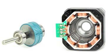
since they are everywhere in our industry today. Before we start in on the details, you need to know ECM motors are fundamentally different from AC inductive motors.
EC motors are direct current (DC) motors, not alternating current (AC). I’ll say it again, EC motors are DC motors not AC. This is why they are so cool, and by adding some electronics we can do almost anything we want with them. Now not to confuse you, they are still hooked up to AC power to run them, it’s just the motor “type” is DC. Ok time to dig in.
Let’s start by breaking apart the three words in ECM. Electronically seems pretty easy, it just means there are a bunch of electronics in the motor to do some calculations for us. It’s far different from your typical induction motor or pump, that just consists of some connections and a bunch of windings to spin the rotor.
The next word is the one you have been waiting for. What the heck is commutated? It’s a weird word, especially in our world. Essentially, and not to over simplify, it’s how the motor knows the position of the rotor.
Now if you remember my last article which broke down the sections of a motor, the rotor is the rotating part in the middle. In the case of a pump, the part that attaches to the impeller. If you
think of older DC motors, and you had to ever change out the brushes, the brushes touched the commutator. The brushes let the motor know the position. In the case of an ECM the electronics know the position of the motor via a rotor position sensor.
We still connect the pump to 120VAC, in most cases, but inside it converts the AC voltage to a DC voltage that it can use to run the DC “type” motor. If you have ever taken apart an ECM junction box, you will see a bunch of big capacitors and then some other electronics that are not found inside a regular AC inductive motor. This is essentially the brains of the ECM.
So then how does the DC motor work? It works on the same principle as any other electric motor. It has a stator that you “electrify” to push and pull (as noted in the last article) the rotor around. Remember that the stator is the electromagnet(s) around the rotor. The rotor is actually what spins. But this is where it gets really cool. Electromagnetism works when you put a current though some windings around a core. The magnetism pole (North or South of the magnet) changes based on which way the current flows through it.
One of the cool things about EC motors is that they can change the electromagnet portions of the stator from a push to a pull, and this is controlled electronically. It can also control how hard to push and pull, which in turn lets us control the speed of the motor. Unlike an AC motor, where the voltage and current go positive and negative, the ECM has full control over that how
it electrifies the stator. It senses the position of the rotor very accurately with the electronic commutator, and can then very accurately set the stator to push and pull the rotor around. With this accuracy comes efficiency.
Efficiency can be measured in many ways, and in the case of an EC motor there actually are many efficiencies to measure. The first being, no brushes, just bearings. There is nothing mechanical to impede the spinning of the rotor. The second, as stated above, is the effective way of energizing the stator at precisely timed intervals. Probably the biggest gain is the feedback efficiency. As you may or may not know, we over pump in North America. Bigger is better, as the old adage says. Well, if you are trying to make an energy efficient system, it does not work that way. Bigger is not better.
Getting feedback to create the exact head pressure, or the exact flow, required for the system is the best approach. As the environment of the system changes, whether just over time or because other valves or pumps are working, the pumps rates can be adjusted. At a minimum, an ECM pump is around 20% more efficient than a
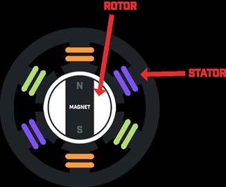
conventional inductive motor pump. Don’t shoot the messenger on the numbers, they are guidelines. Typical inductive pumps have an operating efficiency at a certain GPM. When sizing a pump you try to select the pump where the flowrate or pressure drops fall into the best spot on the curve. With ECM pumps this all changes. When we incorporate the feedback from the system, be that flow feedback or pressure feedback or even temperature feedback, with an ECM the speed can be set to exactly what we need, or what has been designed.
Keep in mind that this feedback can be external or it can be internal. This gives us two-fold efficiency; we gain the electrical efficiency, but we also gain the system efficiency because we all know that if we can hit the proper flow
rate for a system everything in it just works better. Heat transfer is where it should be and velocity is proper so erosion is down. Its win, win.
Now don’t get me wrong, ECM pumps are more expensive, so regular inductive AC pumps have their place, but just as with all devices, as manufacturing ramps up and government efficiency mandates demand to be better, the ECM pump will become more and more prevalent.
So there you have it. An explanation of ECM pumps without getting too political over pump curves.
Next time maybe I'll tell you about my experience with a home-made Taser.<>

Curtis Bennett C.E.T is product development manager with HBX Control Systems Inc. in Calgary. He formed HBX Control Systems with Tom Hermann in 2002. Its control systems are designed, engineered and manufactured in Canada to accommodate a range of hydronic heating and cooling needs commonly found in residential, commercial and industrial design applications.
Due to COVID-19 pandemic visit event websites for the
HRAI AGM
October 1
The Heating, Refrigeration and Air Conditioning Institute of Canada will be hosting its 52nd AGM in a virtual setting this year. All members are encouraged to attend the free event. www.hrai.ca
Retrofit Canada Conference
December 2-3
Being held in the City of Vancouver, the first Retrofit Canada Conference will focus on innovation, sustainability and energy efficiency through retrofitting Canada’s infrastructure and buildings. www.retrofitcanadaconference.com
ISH – International Trade Show for Water and HVAC
March 22-26
The world’s largest exhibition for the HVAC sector held in Frankfurt, Germany showcasing an array of leading-edge solutions. ish.messefrankfurt.com
Alberta
November 04-05
The largest event of its kind in Alberta, the show is to be held in the BMO Centre in Calgary. www.buildexalberta.com
Conference
January 23-37
The technical program for the 2021 ASHRAE conference will be held at the Palmer House Hilton in Chicago. www.ashrae.org/conferences
MCEE 2021
April 7-8
Industry professionals will gather at the Montreal Convention Centre for the Mécanex/ Climatex/Expolectriq/Éclairage (MCEE) 2021 trade show. www.mcee.ca
The Buildings Show
December 2-4
A premiere event for the built environment in Canada, the three-day show is held at the Metro Toronto Convention Centre. www.thebuildingsshow.com
January 25-27
This annual showcase on the future of HVAC/R technology is scheduled to be held at the McCormick Place in Chicago. www.ahrexpo.com
May 5-6
Postponed by a year, the biennial Mechanical, Electrical, Electronic Technology trade show in Atlantic Canada will be held at the Moncton Coliseum. www.meetshow.ca
CIPH Annual Business Conference
June 27-29
The networking event for the Canadian plumbing and heating industry will be held at the Algonquin Resort in St. Andrews, New Brunswick. www.ciph.com
Ventilation 2021
August 15-18
Held every three years, the 13th International Industrial Ventilation Conference for Contaminant Control is taking place in Toronto at the Sheraton City Centre. www.ashrae.org/conferences

CIPHEX West 2021
November 3-4
Western Canada’s plumbing, hydronics, heating, ventilation, air conditioning, refrigeration and water treatment show is being held at the Pacific National Exhibition in Vancouver. www.ciphexwest.ca

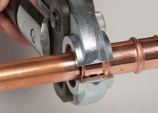
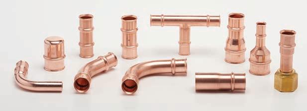
If you’re still brazing every HVAC/R joint, you’re missing out on huge time and cost savings. RLS press fittings create permanent, reliable mechanical joints in just 10 seconds, letting you get in and out of jobs faster – and get more jobs done. Plus, no brazing means no gas, no fire watch and no hot work permits.
RLS press fittings are field proven – with millions installed globally since 2015 – and are approved for field installation in Canada (CRN #0A22551). Flame-free connections are the future (especially with the increased use of flammable refrigerants). So don’t get left behind!
• Millions of fittings installed Finish jobs faster.
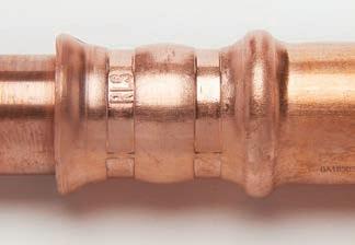
RLS Advantages:
• Connects in 10 seconds
• No gas or brazing materials
• No flame, no fire hazards
• No fire spotters
• No hot work permits
• No nitrogen purging
• Works in tight spaces
• UL listed to 700 psi

The Brute FT® Wall Hung Combination Boiler and Water Heater.
The Brute FT® rises to the challenge, checking all the boxes on your customers’ home and water heating wish list. Its modulating technology automatically adjusts fuel usage to match heat demand – saving up to 20% on heating utility bills compared to standard “on-off” boilers!
The Brute FT® delivers: Water Heating Big Performance
Outstanding Efficiency
Compact Design
ENERGY STAR® Rated
Cost-Saving Operation
Eligible for Many Utility Rebates Built to be the Best®
To find out more about the Brute FT® and other Bradford White products, visit our exclusive For The Pro® website dedicated to the professional: bwforthepro.com