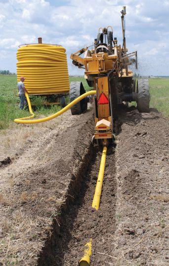
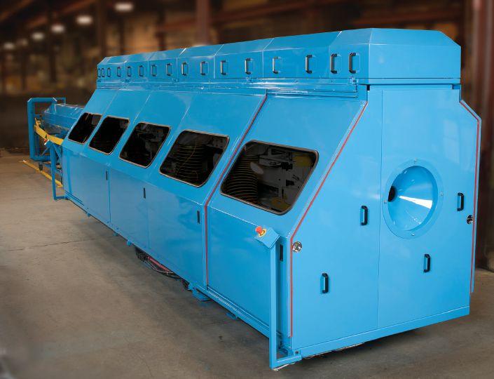
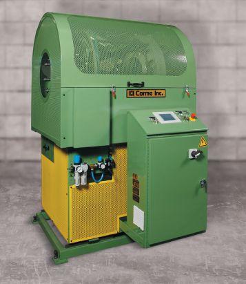
Since 1973, Corma Inc. has continuously innovated to meet the evolving demands of our customers. For example, our 630-12 and 830-12 High Speed Corrugators combined with our HSC Series 2 Adjustable Perforators will produce high quality 4" single wall HDPE pipes at high output rates up to 2,300 lbs/hr and 115' per minute. To learn how we can make a positive impact on your business, please contact: 830-12 Corrugator 2" (50 mm) I.D. to 12" (300 mm) O.D.
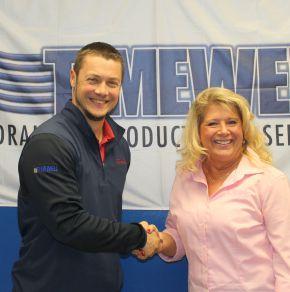
Timewell Drainage Products has acquired Midwest Plastic Products from Spell Capital. Midwest Plastic was founded by Gary Fish and has more than 40 years of experience serving drainage contractors and farmers with high-density polyethylene (HDPE) pipe and accessories.
The company brings robust blow molding capabilities to Timewell’s existing operations, and Midwest Plastic customers will now receive a complete companymanufactured product line, including two-inch to 18-inch single wall pipe and four-inch to 48-inch MaXflo dual wall pipe. Midwest Plastic’s facilities in Jefferson, WI, and Plainfield, IA, will continue to manufacture drain tile and fittings.
Timewell will continue to operate its existing facilities in Timewell, IL, Sibley, IA, and Providence, KY. The company will remain headquartered in Timewell, and Darren Wagner will continue serving as president.
MANITOBA SIGNS ON TO FLOOD AND DROUGHT PLANNING MODEL
The pieces are all falling into place for the Manitoba Forage and Grassland Association (MFGA) Aquanty modelling project for the Assiniboine River Basin (ARB).
Ralph Eichler, Manitoba’s minister of agriculture, recently signed the province’s commitment to the $1.7 million project, adding his signature to Lawrence MacAulay’s (Canada’s minister of agriculture) on the project.
“The Manitoba government is a proud partner on this project,” Eichler said in a press release. “This work will enhance the scientific understanding of how the landscape is affected by flooding and drought, as well as the practices available to farmers that may prevent or minimize these challenges.”
Agriculture and Agri-Food Canada (AAFC), under the Growing Forward 2 AgriRisk Initiative, is the primary funding partner committing $1,145,800. Manitoba Agriculture is the secondary funding partner, committing $180,000 to the twoyear project through Growing Forward 2, a federal-provincialterritorial initiative. The remainder of the $1,732,300 total project funding will be provided by partners
and supporters via a combination of in-kind and cash contributions.
The official signings, said Henry Nelson, MFGA’s vice-chair and project lead, mark a watershed moment for the project going forward.
“Recent flood events in the Assiniboine River Basin have resulted in significant crop losses, property and infrastructure damage, leading to unprecedented AgriRecovery claims above and beyond crop insurance,” Nelson said. “This project seeks to develop new risk management tools to reduce the impact of extreme flood or drought events for the agricultural industry within the basin by identifying preventative measures, implementing risk prevention and mitigation activities, all with the intention of lessening the need for government disaster programming in response to such events.”
The MFGA’s Aquanty project will encompass the Assiniboine, Qu’Appelle and Souris sub-basins, as well as a more detailed drill down on the Birdtail watershed located in the upper reaches of the Assiniboine sub-basin. The project has two key objectives: (1) to develop the customized, user-friendly integrated hydrologic model for the basin, and (2) to develop a detailed, model-
based assessment of how perennial forages, grasslands and wetlands influence the hydrologic characteristics of the basin under conditions ranging from flood to drought, and may play a key role in moderating/mitigating the risks of flooding and drought.
At the end of the project’s twoyear term, MFGA will be one of two licence holders for the final model, the other being AAFC. MFGA is currently developing a strategy to ensure all the key stakeholders are aware of the opportunity to access the model for their best decisions going forward.
“It is anticipated that the model could become a standardized platform for a number of different stakeholders, including multiple levels of government, research institutes, and NGOs [nongovernmental organizations] who want to perform targeted hydrologic analyses and research across a wide range of temporal and spatial scales within the ARB,” Nelson said. “Individuals such as primary agricultural producers and/or the business sector such as the oil and gas sector, may utilize the model on a much smaller scale, right down to individual fields or properties.”
For more information, contact Duncan Morrison, MFGA executive director, at 204-770-3548 or Duncan@mfga.net.
PIONEERING DRAINAGE RESEARCH STORIES NOW AVAILABLE
The year 2015 was the 50th anniversary of the beginning for the corrugated-wall high-density polyethylene (HDPE) plastic drainage pipe manufacturing industry in the United States. Drainage Contractor columnist James Fouss and his colleague, Norman Fausey, conducted the pioneering research with promising results that helped the industry get its start in 1965.
Working for the Soil and Water Conservation Research Division of the United States Department of Agriculture’s Agricultural Research Service (USDAARS) and stationed at Ohio State University, Fouss and Fausey created a paper on the early research project results, which was presented at the first National Drainage Conference held in December 1965. Many details and challenges encountered in the research had never been documented or published, although some special details and events were reported verbally at some engineering meetings. Early phases of the research involved developing improvements in the plastic-lined mole drainage channel concept, but through field experiments the long-term structural stability of the thin-walled plastic mole liner was found to be poor and therefore not acceptable. When corrugated-wall plastic tubing (originally developed in Germany) became available in the U.S. early in 1965, it was adopted for research and evaluation in the USDA-ARS drainage materials phase of the project. The activities and events of the overall research project were written in three main subprojects that made up the
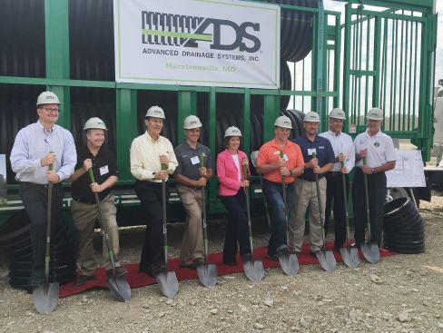
ADS BREAKS GROUND ON FIRST PLANT IN MISSOURI
Advanced Drainage Systems Inc. (ADS) hosted community leaders, elected officials and prospective employees in early October at the site of its new manufacturing facility, now under construction in Harrisonville, MO.
The 72,650 square-foot facility is expected to open in the first half of 2017, bringing new jobs to the region. ADS intends to employ approximately 50 people at the facility when fully staffed, and will hire locally for employment opportunities in management, machine operation and transportation, among others.
The Harrisonville plant will be the company’s 62nd manufacturing plant, and its first in Missouri.
It represents a significant capital investment for ADS, whose growth is a result of favorable policies enacted by the Missouri Department of Transportation (MoDOT).
In 2011, and again in 2014, MoDOT updated its standards specification to allow plastic pipe to be used in statewide infrastructure projects for storm water management. ADS reports demand for its products has grown
comprehensive research project. The three subprojects were written in separate stories, as follows:
• ARS story on research and development (R&D) for the American version of corrugated-wall plastic drainage tubing and plow-in method of installation;
• Story behind the story about the ARS co-op R&D project for laser-beam grade-control on a draintube plow; and,
• Story behind the story on the development of the ARS “Big Red” draintube plow with laserplane automatic grade-control system.
These three stories and supporting documents are now available in PDF format and can be viewed and/ or downloaded from the Transforming Drainage project website (www.transformingdrainage.org). Original printed copies of the research stories and many of the supporting publications and reports were provided as historical reference documents on the pioneering drainage research developments for the Drainage Research History section of the International Drainage Hall of Fame, housed in the department of food, agricultural and biological engineering at Ohio State University.
“It is hoped that the stories may provide some ideas and hints to future drainage researchers with pioneering ideas on ways to overcome barriers to research progress, including limited project funding and skepticism by research administrators, in their own revolutionary research and development drainage projects to further improve drainage technology in the years ahead,” Fouss said. Read about more research Fouss is involved in on page 24.
significantly, including revenue growth of 50 percent since the specifications were first updated.
The event featured remarks from Joe Chlapaty, chief executive officer of ADS, U.S. Representative Vicky Hartzler (R-MO), State Senator Ed Emery (R-Lamar), and Mayor Brian Hasek of Harrisonville.
COMPANY ON THE MOVE
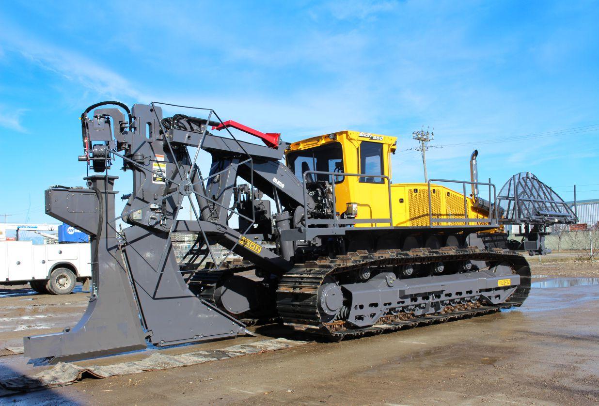
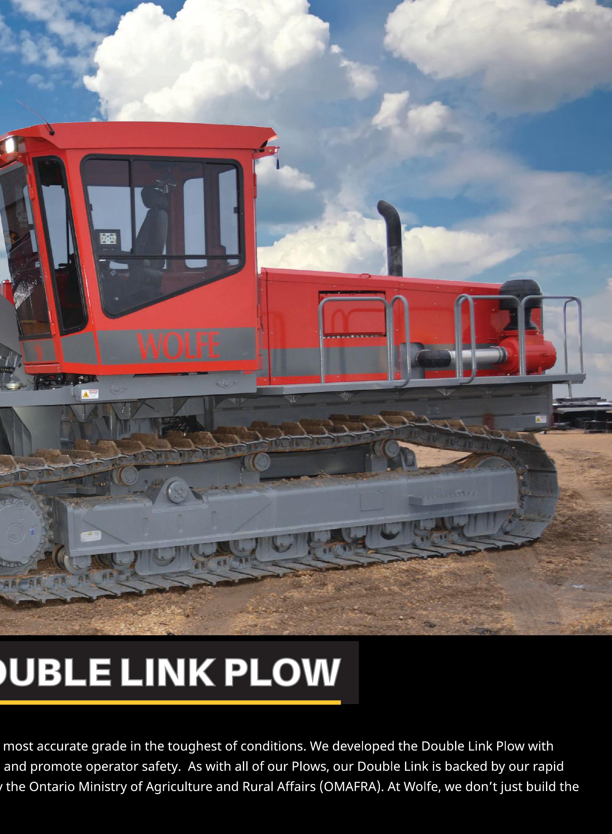
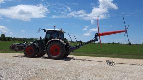
BRON DL850 Double Link Plow
Introducing the new DL850 Double Link Drainage Plow. Based on the proven DL750 architecture, this new plow design increases strength and durability with larger pins & bushings to handle the toughest ground conditions.
The stronger structure is powered by Heavy Duty cylinders designed to increase durability and uses bolt-on glands for improved field servicing.
DL850 Plow features & benefits
• Larger trunnion mounted swing cylinders
• Swing cylinder pins increased in area by 110%
• Increased area on the lower link ‘tow’ pins by 43% (2.5” vs 3.0”)
• Added internal cross-bracing on the larger links to increase torsional rigidity
• All cylinders designed with bolt-on glands to improve service access
• Cylinder pressure ratings increased by 33%
• Blade lock & wedge cylinder pins now 2” diameter
• DL850 blade holder accepts DL750 blades
• Simplified laser-mast/GPS-sensor arm increases stiffness for improved plowing depth accuracy
• External hose routing to improve durability & servicing
The DL850 is available on our 450 and 550 Drainage Plows.
BRON is pleased to announce its expansion into the United States with the opening of our Marine City Michigan, Parts Distribution Center. The main purpose of this facility is to better serve our customer’s parts requirements within the USA and save on shipping and brokerage costs. Most frequently ordered items are stocked at the 6500 sq. foot plant, with the ordering process still taking place through the BRON facility in Woodstock by calling 800-263-1060 or 519-421-0036 or direct e-mail to parts@rwfbron.com.
Everyone at BRON values our customer’s business and will continue to look for ways to improve our products and services.
Joining forces
Everyone benefits when associations collaborate for the greater good of the industry.
by Steven Anderson
In this time of increasing scrutiny of tile outflow and nutrient loss, there remains a lack of data to make determinations about best management practices in terms of fertilization rates and timing, as well as factors such as natural mineralization rates.
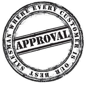
In mid-September, contractor members of the Illinois chapter of the Land Improvement Contractors of America (LICA) began a project in central Illinois, near the town of Macon, for the Illinois Corn Growers Association and the University of Illinois (UofI) designed to generate some of this important data. The project entailed the installation of a new main line and drainage system on a farm owned by the university. The cost of the installation was borne by the Illinois Corn Growers Association and the UofI. There were also considerable in-kind donations by the Illinois Land Improvement Contractors of America (ILICA) and tile suppliers Springfield Plastics, Fratco, River Valley Pipe, and Advanced Drainage Systems (ADS). There was also a much-appreciated contribution of equipment from Altorfer Inc., Birkey’s Inc., Bron, Central Illinois Ag, Martin Equipment, Schlatter’s Inc., and Roland Machinery Company.
An additional contribution by Agri Drain is what made this a unique system. Thirty-seven Agri Drain control structures were installed in the drainage system. These structures were placed to isolate areas of drainage, enabling samples to be taken from individual control areas to determine how different rates and timing can affect outflow of nutrients through a tile system. These control structures were placed at the inflow point into the main and isolated by stretches of solid pipe about 20 feet upstream in order to limit bypass seepage around them when the control boxes are closed. The resulting data should greatly add to the knowledge of what comes out the end
of a drainage pipe, and why. This information is needed to combat speculation, as tile is increasingly being looked at as a pollution source and not as the essential production tool it really is in most areas of the world.
Several more sites are under consideration for replicating this system in the future, to both verify results and increase the amount of data available.
Projects like this one are what make LICA a unique trade association: a group of contractors can get together to collaborate on a job with benefits for their industry as a whole, and the association itself. While these guys may be competitors in the areas they generally operate in, they are also friends through LICA, where they have gotten to know each other over the years at conventions, workshops and shows. Several contractors made considerable contributions in terms of time, equipment, and manpower, bringing their crews with them to work on the project. One doesn’t often see this in other trade associations.
There really is a family feeling to LICA. When a member takes the time to get involved, that member begins to see what the real value of their membership can be. There is a lot of knowledge gained in the trenches (pun intended). Those who get involved in a project like the one in Illinois take away more than they give: they find it fun to work together with the group and share together as friends after the day is done.
If you’re interested in getting involved in projects like the one in Illinois, consider joining LICA. Most of the state chapters work on projects aimed at increasing knowledge among contractors and building a stronger drainage industry. DC
Steven Anderson is chairman of the board of the Land Improvement Contractors of America.
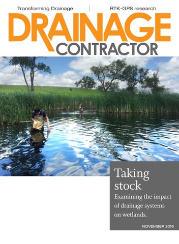
TAKING STOCK
South Dakota researchers are examining
the
impact of drainage systems on wetlands.
Wby TRUDY KELLY FORSYTHE
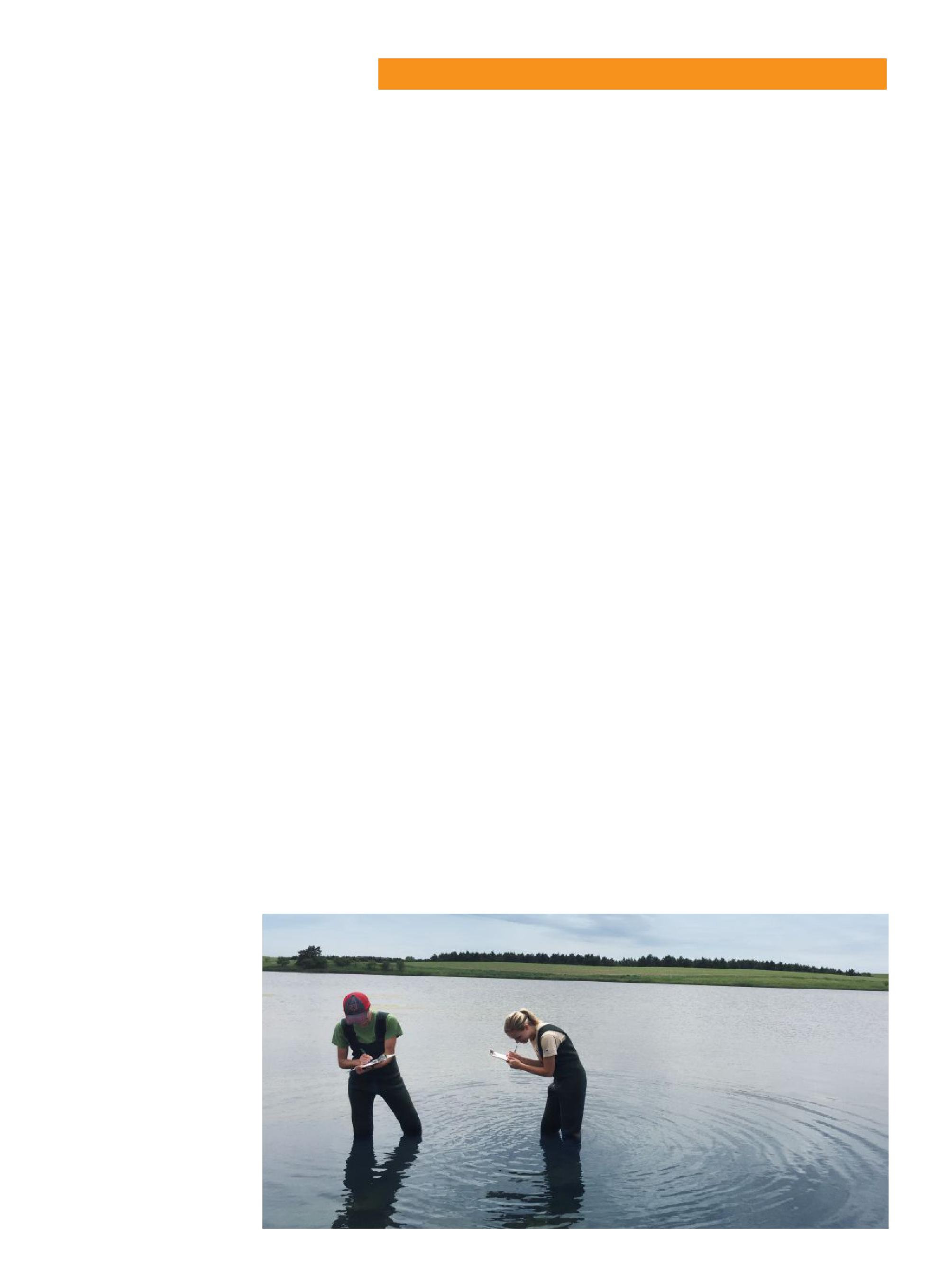
Students from the University of South Dakota collect data as part of a study to determine the impact of agricultural drainage on wetlands.
Photo courtesy of Jake Kerby.
hen Matt Schwarz, an environmental contaminants specialist with the South Dakota Ecological Services Field Office for the U.S. Fish and Wildlife Service (USFW), noticed more and more farms installing drainage systems, he began to wonder what impact
this might be having on the area’s
So, he turned to Jake Kerby, an associate professor at the University of South Dakota, to study the situation.
“Because the U.S. Fish and Wildlife Service has a number of water fowl production areas, he noticed tile drains collecting in outlet points and draining right into the wetland,” Kerby says. He explains there were a variety of scenarios, including surface runoff from farms, some buffered sites and some with pipes going directly into the wetlands. “He wanted to know what impact this was having on water quality.”
To find out, Kerby and his research team selected 18 sites to study. Six receive tile input directly, six receive runoff from agriculture land and six are buffered. The team surveyed the sites and collected water quality data over the past four years to find out exactly what is coming out of the pipes.
CHEMICALS FOUND
wetlands.
What they found, both coming out of the pipes and within the wetlands, is a higher level of two different chemicals.
One is a relatively new group of insecticides, called neonicotinoids (or neonics). Kerby hypothesizes neonics may be a culprit because they are chemically similar to nicotine, and can be lethal to insects as they can bind to neuron receptors and stay there.
“They are good for agriculture because they can apply it directly to the seed, so it is seen as an advance because not as much spraying is needed,” he adds. “In farmlands, it is underground so should be well contained, but drain tile is underground so when the seed is washed off, it precipitates down to the pipes and is carried through the pipes.”
The second chemical they discovered
was selenium, which they found in higher levels at the sites with pipes from drainage systems. “Selenium is naturally occurring in South Dakota soil but through farming, a lot of it has been removed,” Kerby says. “However, deeper down in the soil, it’s still there and because they bury the pipes low, it is getting into the pipes and is carried away.”
WETLAND DIVERSITY
As well as measuring what was in the water, researchers examined what isn’t in the water. “We don’t have the final analysis yet but early results indicate at our tile sites we have lower diversity and higher neonics and selenium,” Kerby says. “It could be the insecticide. It could be the selenium. It could be higher nitrogen and phosphorus.”
The researchers found fewer insects and less aquatic vegetation at the sites with drain tile and the insects they did find had higher levels of selenium in them. They did not look at neonic levels, as these are harder to measure. As well as fewer insects, Kerby says the timing of when insects emerge in the pond has shifted at the tile sites, with fewer emerging in June and July than typical.
“When you’re looking at a waterfowl production area, the ducklings feast on these emerging insects,” Kerby says. He adds they do not have a waterfowl specialist involved in the project yet to see what impact this might be having, but they do see fewer amphibians. “This may be linked with fewer insects.”
And in all cases, the differences are incremental based on the subset. “The control sites are better than the surface sites, which are better than the tile sites,” Kerby says. “The tile sites are worse than surface runoff alone, likely because there’s a lot of vegetation and soil to block and filter a lot of things.”
MOVING FORWARD
The researchers are currently seeking additional funding to continue the project. The goal is to collect enough data to inform policy-makers and management leaders, but Kerby also believes there is an engineering opportunity.
“There are two types of pollution: point-source pollution, such as when you have pipe from [a] mill dumping
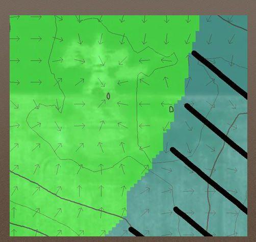
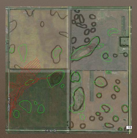
A watershed map with arrows illustrating the direction water flows. This is layered with maps from USFW and NRCS to determine how close North American Drainage can go with its drainage system.
pollution into a river, and non-point pollution,” he says. “Agriculture has always been non-point pollution because you can never be 100 percent sure where pollution is coming from. It could be Farm A or Farm B.”
One opportunity presents itself in being able to identify the source and manage any issues there. Another is to treat the water properly as it leaves the system through a single pipe.
ONE COMPANY’S PROCESS
Gabby and Tyler Heinsohn, the owners of North American Drainage in Aberdeen, SD, believe collaboration is one of the keys to protecting the environment and improving agricultural land. That’s why they work with government agencies to ensure their systems have minimal, if any, impact on protected lands.
“It was our strong desire to be proactive ambassadors for the drainage industry in our area,” Gabby says. “We reached out to local agencies and collaborated on a process that facilitates co-operation on all fronts.”
The Heinsohns consult with USFW and Natural Resources Conservation Service (NRCS), obtaining maps detailing protected lands and water sources that they overlay with a satellite image for a more comprehensive picture of the area. They then combine that information with the topographic data they gather from their surveying process to develop a design that is conscientious of that land’s watersheds.
“Some protected areas can neither
have water removed or added to them,” Gabby says. She explains they layer watershed maps from USFW and NRCS to determine how close they can go with their drainage system. “Each agency has its own formula or policy regarding buffers that are to be taken into account as well.”
Gabby says runoff is actually reduced when soil is properly drained rather than when left saturated or highly compacted.
“Properly drained soil allows for more absorption, which in turn keeps chemical applications in the desired area of the crop,” she says. “It also effectively decreases the amount of chemicals needed to be applied in order to achieve desired results. We support the theory of prescription farming, where only what’s needed need be applied. We also encourage the use of surface drainage with the use of a grass waterway.”
In a grass waterway, the grass helps prevent soil erosion and provides some filtration of surface runoff.
The Heinsohns recognize their process is not a definitive solution but they hope to further improve it through continued collaboration. And there is interest in their process. Tyler recently presented the company’s method of calculating setback distances for wetland and easement boundaries to more than 100 USFW employees from South Dakota, North Dakota, Minnesota, Nebraska and Montana.
“We received positive feedback and the interest to have other contractors start implementing similar methods,” Gabby says. DC
INDUSTRY NEWS
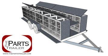
THE PARTS TRAILER
BIOREACTOR STUDY SECURES FUNDING
The Minnesota Department of Agriculture (MDA) has awarded a Clean Water Fund research contract to a project that will evaluate the effectiveness of bioreactors in treating tile water.
Carl Rosen from the University of Minnesota’s department of soil, water and climate will research, demonstrate and evaluate the effectiveness of woodchip bioreactors for treating agricultural tile water. The project will be conducted using a unique, replicated field-scale experiment that allows analysis of two variables that have the potential to enhance bioreactor performance.
The project is unique in that it will carefully monitor microbial performance using genetic and genomic technologies, and modify properties that facilitate removal of nitrogen and phosphorus. Increasing the efficiency and effectiveness of bioreactors may reduce the cost and increase adoption of the practice.
For additional information, visit www.mda.state.mn.us/ cleanwaterfund/research.
The 2017 Parts Trailer has user adjustable bins of varying sizes to accommodate all the necessary tile fittings needed to install and/or repair tile. All parts are easily visible from outside the trailer so that with one quick glance you know exactly what you have in the field or on hand in general. The trailer is 20 feet long with full-length center shelves and four 10-foot bolt-on bins, each of which can accept up to seven divider panels. LED lighting, full powder coat paint, and tandem torsion bar axles complete the trailer. www.thepartstrailer.com.
Water recycling feasibility
by Ben Reinhart
The latest on the Transforming Drainage project.
The Transforming Drainage project is capitalizing on the network established during our first year with new research to advance our understanding of drainage water storage systems (e.g. controlled drainage, saturated buffers, and drainage water recycling), foundations for innovative tools, and continued outreach to stakeholders across the Midwest. Research in Iowa, led by Chris Hay of the Iowa Soybean Association and Matt Helmers of Iowa State University, evaluated the feasibility of drainage water recycling systems to meet growing season irrigation requirements for corn and soybeans across 12 locations and 17 years between 1990 and 2011. Rain-fed cropping systems, which predominate across much of the Midwest, rely on seasonal rainfall to meet crop water requirements. If the amount of rainfall infiltrated and stored within the root zone cannot meet crop water requirement during certain periods, then a water deficit exists and supplemental irrigation can potentially increase crop yield. This study found there was an average water deficit of nearly six inches for soybeans in Ames, IA, over the study period. This represents a worst-case scenario, since soil water stored in the root zone in the spring was not included in this assessment. Deficit amount tended to increase from east to west and from north to south across Iowa. After comparing water deficits with the drainage volumes from Iowa State University drainage research plots, storing subsurface drainage water could potentially have been sufficient to meet the demand for irrigation in nine of the 17 years, even at this upper limit of water deficit. “This research provides a great foundation for future work in evaluating the impact, both in regards to crop yield and water quality, and management strategies for drainage water recycling in Iowa and elsewhere across the Midwest,” Hay says. “As we continue to refine the research to incorporate soils information, impacts on crop yield and economics across more sites, we can better understand the feasibility of this practice.”
In other efforts, Mohamed Youssef, agricultural engineer at North Carolina State University, led the development of an approach to estimate the impact of controlled drainage systems on reducing annual drainage volume and nitrogen loss. Using the field-scale modeling program, DRAINMOD, the team at North Carolina State conducted thousands of simulations across various climates, soil types, drainage designs, and cropping scenarios in the Midwest. The results were used to build simple statistical relationships that estimate annual drainage volume and nitrogen loss as functions of readily available data (e.g. precipitation, soil texture, soil organic matter, depth and spacing of tile drainage, grown crop, fertilizer rate). This will allow users to define site-specific, and management-specific, estimates of how much tile drainage water and nitrogen would be expected under both free drainage and controlled drainage scenarios. Packaged as a web-based interface, these regional empirical equations could represent a user-friendly tool for future drainage system designers and planners.
The Transforming Drainage project has now joined social media as another way to share work from the project. Folks can follow us on Twitter @TD_drainage and participate in the conversation using #transformingdrainage. One of the primary goals of the Transforming Drainage project is to support and grow the network of individuals and organizations out there working in agricultural drainage. Sharing ideas and feedback on tools, research and outreach or education opportunities is a great way to participate in the Transforming Drainage project and can lead to greater collaborations down the road. We encourage you to visit the website (www.transformingdrainage.org), sign up for our online newsletter, and follow us on social media. We look forward to working with all of you to advance drainage water storage for more resilient cropping systems. DC
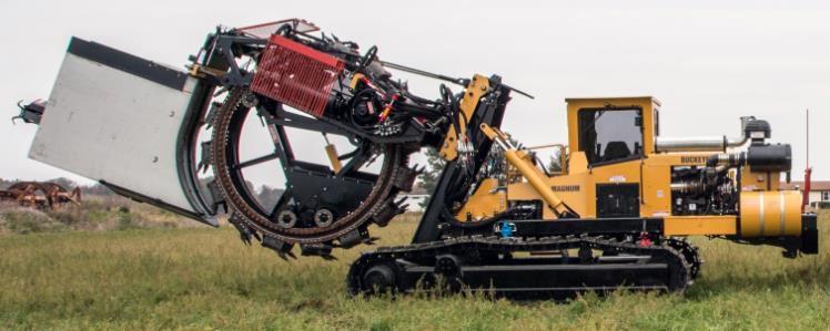
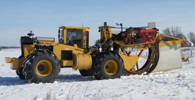
•Wider cab model
•Variable angle arc plate
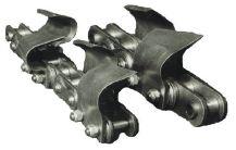
•Quick change teeth (reversible)
•Tubing chutes up to 16 inch
•GPS or Laser Guidance •Up to 7ft cutting depth •High production •Low ground pressure •Robustly built plow and frame
ENVIRONMENT
P IN SURFACE RUNOFF
The challenge of keeping nutrients in the root zone year-round highlights the importance of bundled BMPs to prevent runoff.
by TIM HARRIGAN
Patience is wearing thin in some communities because of water quality problems linked to the loss of crop nutrients from agricultural land and other sources. The city of Des Moines, IA, is moving ahead with a lawsuit against three of the state’s highly agricultural counties that manage drainage districts traced to high concentrations of nitrates in the Raccoon River, a major source of drinking water for the city.
Des Moines officials claim tile drains should be regulated as point sources under the Clean Water Act. Nonpoint pollution sources now make up the largest source of total phosphorus (P) leading to excessive algae growth and disruption of fisheries in Lake Erie.
Much of the most productive farmland in Ontario, Michigan and Ohio is tile drained. While drainage has economic and environmental benefits, under some conditions excess nutrients from commercial fertilizers and livestock
manure can quickly move to tile drains through preferential flow paths and thereby escape from the field.
Merrin Macrae, associate professor at the University of Waterloo in Ontario, opened a conference sponsored by the Michigan chapter of the Soil and Water Conservation Society and Michigan State University Extension in East Lansing on March 4, entitled A Matter of Balance: Systems Approaches to Managing the Great Lakes Landscapes. Her presentation summarized the results of work with farmers in southern Ontario in tracking nutrient cycling and water quality impacts from surface runoff and tile-drained lands to Lake Erie tributaries.
Southern Ontario farms are largely in cornsoybean-wheat rotations similar to many farms
in Michigan and Ohio. Macrae’s research group worked with several progressive farmers (ANSWERS group) and had help and funding support from the Ontario Ministry of Agriculture, Food and Rural Affairs (OMAFRA) to establish year-round sampling sites to measure runoff of both overland flow and tile drainage. The soils were silt loam, clay or sandy loams. Soil test P averaged 14 parts per million (ppm), ranging from five to 25 ppm with a tile depth of three feet and spacing ranging from 30 to 45 feet. Various low disturbance tillage practices were used. Commercial P was subsurface banded and poultry litter was used at one location.
In Ontario, precipitation is fairly well distributed throughout the year with no real predictable wet or dry periods, but runoff is highly seasonal. Very little runoff occurs during the growing season unless there is a huge storm; most rainfall is stored in the soil profile and is used by the crop. Most runoff occurs during the non-growing season. Typically, 80 percent of runoff occurred between October and June, with most of that at snowmelt in March. Because P loss was proportional to runoff, most nutrient loss occurred in the non-growing season, with most losses during spring snowmelt. During the growing season, the nutrient loss was linked to
QUALITY IN.
runoff following heavy rainfall events, so maintaining crop residue cover and other erosion prevention BMPs was important.
Nutrient loss from tile drains has come under close scrutiny in recent years. In Ontario, Macrae measured much higher P concentrations in the surface runoff than in the tile drain effluent. Compared to tile drainage, surface runoff was a much “hotter” source of P. At one site, surface runoff was only a minor contributor to the total runoff volume, but it was a major contributor to dissolved reactive phosphorus (DRP) loss. Tile drainage contributed most of the total runoff but overland flow carried most of the nutrients. Most of the total annual P loss was particulate P carried by sediment in runoff during snowmelt.
The timing of nutrient application and soil test P was important. When commercial P or poultry litter was applied in the fall, autumn rains led to spikes in tile drainage P. Late fall and all applications on the frozen ground should be avoided. Very early fall or spring applications carry less risk.
No-till cropping is associated with better soil aggregation and structure, but with little tillage nutrients can concentrate near the surface where they are at risk of loss to overland flow. No-till soils tend to have greater macropore development, which can enhance rapid movement of nutrients to the tile drains. Periodic tillage may break the flow paths and mix the nutrients more evenly throughout the root zone and thereby reduce soil test P at the surface. Subsurface placement of fertilizer P will help reduce surface stratification. Cover crops, buffer strips, grass waterways and other forms of vegetation to slow water movement and retain sediment are proven methods for reducing sediment and nutrient loss. There is some concern in northern locations that some winter-killed covers can release soluble P but the risk differs by species.
On a watershed basis, current estimates are that Michigan, Indiana and Ohio farmers in the Lake Erie watershed are losing about 1.5 pounds per acre of P per year. Logic dictates losses would be similar in the Saginaw Bay watershed. The goal for Lake Erie is to reduce losses by about 40 percent, to less than one pound per acre in the western basin. In Ontario, Macrae measured consistent field losses on the cooperating farms of less than half a pound per acre per year, even in wet years. The low losses were achieved with strategically low soil test P and subsurface banding or immediate (before rainfall) incorporation. Crop rotations, cover crops after wheat, residue management, rotational or minimum tillage after wheat, no nutrient applications in late fall or on frozen ground and the use of multiple, bundled BMPs held crop nutrients in the root zone for crop use.
The challenge of keeping nutrients in the root zone year-round highlights the importance of using multiple barriers with stacked and/or bundled BMPs to stabilize cropland and prevent runoff. Monitoring and sampling throughout the non-growing season, and particularly during snowmelt and early spring, is critical for truly understanding the timing and quantity of nutrient loss. Most runoff and nutrient loss occurs at snowmelt. Overland flow tends to be the “hottest” source of nutrient loss so select BMPs that slow the water down. Avoid late fall nutrient applications and all applications on frozen ground. Spring applications carry less risk. Banding carries less risk than surface broadcasting, but when nutrients are broadcast they should be incorporated before rainfall because the most loss occurs with the first rainfall events.
This article was originally published by Michigan State University Extension. Reprinted here with permission. DC
TESTING TECHNOLOGY
Reviewing the accuracy of RTK-GPS installations.
In
the hallways at Land Improvement Contractors of America (LICA) conventions, outside the classrooms of drainage workshops, and during informal conversations amongst contractors and vendors,
the topics of RTK-GPS
accuracy
and plow capabilities are frequently discussed.
by BOB CLARK III
It’s not uncommon for contractors to provide their opinions on plow types and the pros and cons of various methods of installation. It’s also recognized that there are no formal industry tests or certifications required of a professional contractor’s operators, machinery, or computer control systems in order to install subsurface drainage tile (corrugated-wall plastic drainage pipe) in the United States. In Ontario, by contrast, there is a certification program in place for drainage plows and contractors. To my knowledge, there are no pull-type plows certified for contractor use in Ontario. We mention this not to speak out against pulltype plows, or new technology, so much as to highlight an interesting point: these frequent
conversations amongst contractors are not just to pass the time, rather they allude to a very important but often unspoken concern across the industry: just how accurate and capable are our drainage installation machines, controller systems and operators? So it was with surprise and enthusiasm that I accepted a request from Jim Fouss to help explore these issues. Fouss was concerned that no testing and/or certification of drainage plows or contractor-operators had been adopted in the U.S., especially as modern drainage plows are capable of operating much faster than in the past. I thought the results would be of interest to all contractors. I was also excited to work with a pioneer in the use of laser-beam and plane
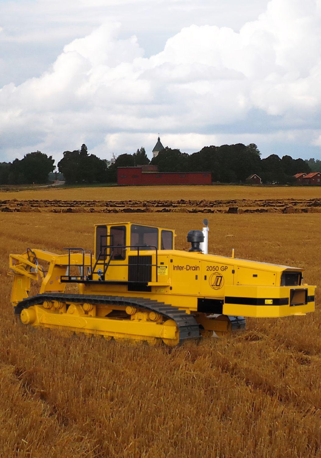
RIGHT: The 2016 Inter-Drain 2050 GP shown with three RTK-GPS receivers. Photo courtesy of Clark Farm Drainage.
Land Improvement Contractors of America
technology in the drainage industry. Much of Fouss’s early work focused on developing and testing laser technology for machine control, especially the drainage plow. He mentioned to me that he was surprised to see such broad acceptance of the use of GPS technology, when there was so little university- or industry-based research and testing reported in the literature; just decades earlier, the adoption of laser-plane technology faced tremendous uphill battles and required demonstrated proof that it worked. “I guess people were just more suspicious of new technology back then,” Fouss said to me. I mentioned that I thought there was significant interest in the topic by contractors, and we decided to get to work.
In brief, Fouss’s idea was to propose and pilot a testing process for the evaluation of RTK-GPS-based drain installations. We decided to make our focus twofold. First, we would focus on developing a process to identify potential differences between elevations recorded based on the cutting blade position of the drain plow and the feeder boot position (the position where the pipe is actually installed). Second, we would focus on deviations between the RTK-GPS drainage system design data and the RTK-GPS data recorded during installation. In this article I will discuss our efforts to evaluate the former.
Evaluating deviations between the position of the cutting edge of the plow blade and the pipe boot are important to contractors for two reasons: 1) the recorded position of the cutting edge is typically the documented position of the drain tile for record-keeping purposes; 2) these deviations may vary based on plow type, how the boot is attached to the plow, soil type, installation depth, installation speed, and pipe size as it affects drag and thus the mechanics of grading.
DIGGING INTO THE DETAILS
Many new drainage plows are now fitted with two RTK-GPS receivers: one on the tractor for steering and one above the cutting-edge of the plow blade for grade control. Different drainage plows are often fitted with different size and shape cutting blades or “shanks” and pipe boots. There are also
Blade and boot RTK receivers. Photo courtesy of Clark Farm Drainage.
numerous configurations for attaching the boot to the cutting blade. In general, the idea is that the blade will act as a rudder, pitching up and down in the soil to cut a trench bottom at the correct elevation, while three additional things happen: a groover forms the appropriate trench bottom for the pipe type and size being installed; a ramp or angle lifts and grates the soil to create finely milled initial backfill; and a pipe boot floats behind the plow blade in order to lay the pipe in its desired location at the bottom-center of the grooved trench. This freedom of movement between the boot and the blade is important, as it allows the boot to maintain a position on the bottom of the plowed-trench as the blade articulates during grading. The configuration and shape of the boot are critical to correct installation, trench bottom, and backfill.
But is the back of the boot always on the bottom of the trench? And is the trench bottom always at the same elevation as the plow blade was when it made the trench-bottom cut in front of the boot?
In order to pilot a process for answering those questions we deployed a third RTK-GPS receiver mounted directly above the pipe chute on the pipe boot. Fouss proposed this approach in an article published in the November 2014 issue of Drainage Contractor. We recorded real time RTK-GPS data during installation of drains for the cutting blade position and the pipe chute position. We then graphed and subjected the data to statistical analysis in order to evaluate the magnitude and significance of any deviations between the blade and boot elevations. We did this for a number of drain lines of varying lengths, and occasionally varying depths, installing the drains both up and down grade, plus various installation speeds with emphasis on the higher speeds, and across a few soil types. The trials were conducted during dry summer conditions in predominately silt loam and silty clay loam soils underlaid with significant clay restrictive layers.
We used Trimble TMX RTK-GPS systems on a 2016 Inter-Drain 2050 GP drain plow to evaluate installation of a
drainage system designed on the Trimble Farmworks desktop application. Technical support and additional equipment were provided during the field trials by Ron Schlatter of Schlatter’s Inc., John Downey, ag sales at Trimble, and Josh Shuler, WM technical product manager at Trimble.
SAMPLE DATA
For this article, we have chosen two sample graphs indicative of result from the trials.
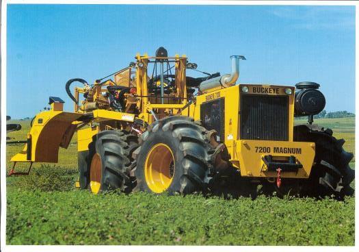
Figure 1 shows drain installation accuracy on the scale of hundredths of a foot. This is indicative of exceptionally accurate and precise RTK-GPS sensing equipment, coupled with extremely precise machine control, grading and boot placement.
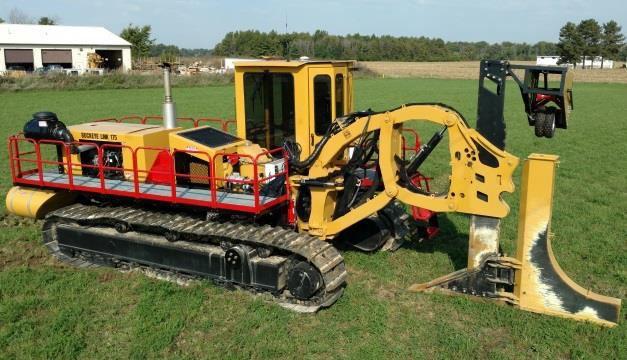
Figure 2 shows plow blade and boot position data for a segment of changing grade drain installation. The graph shows the elevation of the pipe boot and plow blade for a number of positions along the drain line to be very precisely in synch.
ASSESSING THE DATA
We also plotted the latter graph with an expanded Y-scale
Line through Installed Drain
Fig 1: Regression line for a segment of constant grade drain installation. This graph shows drain installation accuracy on the scale of hundredths of a foot. This is indicative of exceptionally accurate and precise RTK-GPS sensing equipment, coupled with extremely precise machine control, grading and boot placement.
Fig 2: Plow blade and boot position data for a segment of changing grade drain installation. This graph shows the elevation of the pipe boot and plow blade for a number of positions along the drain line to be very precisely in sync. Figures courtesy of James Fouss and Bob Clark III.
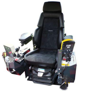
Double Trimble TMX set-up. Photo courtesy of Clark Farm Drainage.
(e.g., 92.4 to 93.6) to better illustrate the differences between the plow blade and pipe boot RTK-GPS plotted data. After data collection and analysis, we were pretty amazed and pleased with the consistency and accuracy of the RTK-GPS equipment, as well as the precision and ability of the plow boot to maintain an appropriate location at the bottom of the cut and formed trench during pipe installation. We expected to encounter more anomalies in the data, but they just weren’t there. However, we need to add that a similar field-based evaluation should be done for other types and configurations of drainage plows.
From the data analysis, we concluded the current, conventional practice of using the plow blade’s recorded position for mapping the installed position of the drain tile is likely sufficient in most applications. However, some outlier scenarios are still possible. For example, in sandy saturated soils, a floating beam plow would require special attention from the operator to maintain proper boot placement, as the plow boot could tend to “sink.” Also, we can imagine a
scenario in which a plow installing a large diameter pipe with a large boot at significant depth would tend to experience more drag, requiring special attention from the operator to maintain proper boot placement, as the plow boot could tend to rise off of the trench bottom.
LOOKING AHEAD
As noted previously, particular plow configurations and soil conditions may impact results. However, the technology to readily test and verify installation practices to a very high degree of precision and accuracy does exist. As plow speeds increase, equipment and technology evolve, and installation practices change, Fouss and I suggest that a certification program of some sort be adopted by the industry. It is also our intention to discuss the results of our continuing analysis of drain versus actual installation in the May 2017 issue of Drainage Contractor. DC
This article was written in partnership with James (Jim) Fouss, PhD, P.E.
BE PREPARED
Planning for a successful OSHA inspection.
Occupational Safety and Health Administration (OSHA) inspections can be stressful for contractors and are usually conducted without advance notice.
There are, however, circumstances under which OSHA may give advance warning to the employer, although it will usually be less than 24 hours’ notice. Advance warning may be given in imminent danger situations, investigation of a fatality and incidences where select people must be present.
Employers who receive advance notice of an inspection must inform their employees’ labor representative or arrange for OSHA to do so. If an employer refuses to admit an OSHA compliance officer, or if an employer tries to interfere with the inspection, the OSHA Act provides for legal action.
HOW THE INSPECTION UNFOLDS
OSHA inspectors/officers should come to your facility prepared, understanding relevant facts about your contracting business, such as its inspection history, its known potential hazards and the specific standards that might apply. Inspectors should show appropriate credentials, and as an owner, you can call the federal or local OSHA office to verify credentials.
An opening conference including involved parties and the OSHA team begins the inspection process. The conference covers the purpose of the visit, the scope of the inspection and the applicable standards. A copy of any employee complaint can be given to you at this time. The act does not require that an employee representative be present for an inspection. However, when no employees are in attendance, the compliance officer must consult with a reasonable number of employees concerning safety and health matters.
The compliance officer determines the length of the inspection and the areas to be covered. Safety and health conditions and practices are observed. Employee discussions are private. If necessary, the inspector takes photos and videos, measures instrument readings and noise levels, examines records and monitors employee exposure to toxic substances.
During the inspection, OSHA pays special attention to posting and recordkeeping requirements, such as totals from the last page of the OSHA Form Number 300 and the OSHA workplace poster (OSHA 3165), which explains employees’ safety and health rights. Records of toxic substances and harmful agents are also requested. Under OSHA’s Hazard Communication Program, employers must establish a written, comprehensive communication program that includes provisions for container labeling, material safety data sheets and an employee training program.
A closing conference completes the onsite inspection. The employer and all others involved then receive a copy of Employer Rights and Responsibilities (OSHA 3000). The inspector will discuss all unsafe/unhealthy conditions observed. The inspector will not indicate any specific proposed penalties, but will inform the employer of his or her appeal rights. During this time, the business owner may produce records of compliance efforts and information to help the inspector determine abatement time frames. If laboratory results are required, or when the hazard affects employees, OSHA may request one more closing conference.
by CNA Financial
PREPARING FOR AN OSHA INSPECTION
At a minimum, employers should: display the OSHA poster entitled, “Jobsite Safety and Health; It’s the Law”; always record injuries sustained on the site; develop procedures to notify management of potential hazards; have an “action plan” ready for an inspection; and coach all employees on the site how to respond appropriately to the inspector’s inquiries.
Understanding your hazards and controls for injury prevention is key. If you have had any incidents and/or accidents, make sure you have conducted a root cause analysis. Even if the causes are unrelated to your business, make sure you have addressed them, as OSHA may decide to investigate.
Have a clear documented history of all incidents and accidents. Maintain all appropriate recordkeeping, including training programs and records. If you have a health and safety manual, make sure it is updated with current OSHA standards.
Ensure that your site is organized and clean. Hazardous, flammable and combustible materials and products should be properly stored. Have your emergency evacuation plan updated, if needed. First aid kits and fire extinguishers should also meet current OSHA standards. DC
The purpose of this article is to provide information, rather than advice or opinion. CNA does not endorse any coverages, systems, processes or protocols addressed herein unless they are produced or created by CNA. For more resources, visit www.osha.gov.
•
•
GROWING WITH THE MARKET
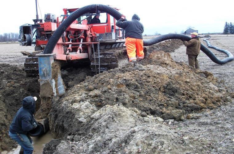
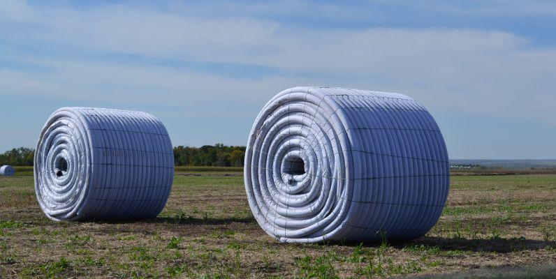
Increasing demand for subsurface drainage in Western Canada has helped Bo-Russ Contracting expand its business.
When long-time friends Sid Boeve and Tyler Russell started Bo-Russ Contracting in Manitoba in 2007, it was just a matter of time before installing tile drainage became one of their services.
by TRUDY KELLY FORSYTHE
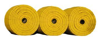
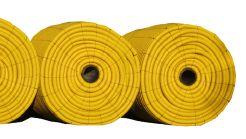
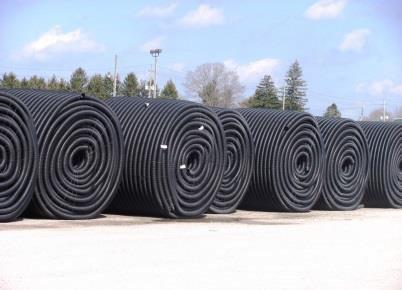
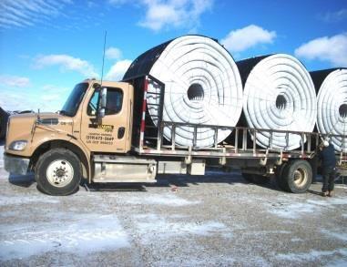
Rolls of four-foot perforated drain with geotextile fabric filter. Geotextile fabric filter prevents soil from entering the pipe, allowing pipe to drain to its full capacity.
Photos courtesy of Caroline Boeve.
While tile drainage is not new to Western Canada, the demand for it wasn’t there until recently because of lower land prices and the cost of tile drainage.
“As the price of land has increased, farmers have begun to look for tangible ways to improve their existing land and its productivity,” Boeve says. “Farmers have realized that improving their land makes sense financially, and more farmers are aware of the benefits of tile drainage. The technology seems to prove itself.”
Wet seasons help with the proof as well.
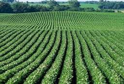
“With a year like the one we are having, you can drive around the countryside and easily identify which fields have tile drainage installed
and which don’t by looking at the quality,” Boeve says. “It makes it very easy for the farmers, and any neighbouring farmers, to see the benefits of installing tile drainage.”
THE BUSINESS
Boeve and Russell established Bo-Russ Contracting in the fall of 2007 to offer drainage and excavation services to the farmers in the area surrounding Carman, MB. Boeve had spent seven years working for a large-scale tree farm, learning first-hand the importance of drainage and irrigation.
Boeve took care of the installation and operation of the irrigation systems and solving
drainage problems, while Russell – who also operated his family’s farm just northeast of Carman, where the business was initially located – helped manage the business and allowed them to stay closely connected to the agricultural foundation of Bo-Russ Contracting.
Together, Boeve and Russell envisioned a company committed to providing excellent customer service and that’s one reason tile drainage didn’t become one of their service offerings until 2011.
“We began with excavating, ditching and surface drainage,” Boeve says. “We always wanted to do tile drainage and we recognized that this was a great opportunity, but we were basically just a small business starting up and trying to get our feet on the ground.”
They passed on an opportunity with investors to enter the tile drainage business earlier, deciding to wait until they could do it on their own.
“We knew there was local demand and that this would be another opportunity to work with our existing customers,” Boeve says. In 2011, when an area tile builder was looking for a local business to become a proper installer, the time was right. Thankfully we were in a position to expand our business when that opportunity arose.”
That spring, they purchased a Wolfe tile plow and began specializing in the installation of complete drainage solutions to help farmers manage excess water and improve their crop yields.
Russell remained with the business until 2014, when he decided to focus his time and energy on the family farm. Today, Boeve operates the business at its new location in Carman with his wife, Caroline, remaining true to his and Russell’s vision of providing excellent customer service.
As well as tile and drainage solutions, Bo-Russ Contracting specializes in GPS topography mapping, excavation and building site preparation. The company uses the newest and most up-todate technology to provide its clients with high-quality and accurate services.
The business currently focuses on the Manitoba market.
“We have been servicing clients within a three-hour driving radius of Carman and I believe we will continue to focus on our customers in that region for the foreseeable future,” Boeve says. He adds the current high local demand for drainage, as well as for the company’s other services, generate enough work that, for now, Bo-Russ isn’t looking to expand its service area.
“We have built a great customer base and typically end up working on other projects for the same customers in the following year and generally we get the opportunity to work with their neighbors as well,” he adds. “Most of our new work comes to us from satisfied customers who refer others.”
The tile drainage business is not without its challenges. Boeve says the biggest one is the paperwork involved with starting a project.
“Each project requires an application to be submitted to the affected municipality, as well as an application to Manitoba Water Stewardship [the province’s drainage licensing department],” Boeve says. “Most municipalities have their own policies, as well as every area and water stewardship zone. You need to be able to get on-board and understand that you have to be flexible as each municipality governs the idea of tile drainage differently.”
Certain areas also face more water issues, which tends to mean
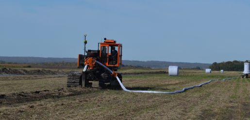
Sid Boeve and his tile drainage crew installing a complete tile drainage system that provides landowners a water management system with numerous benefits.
more people are involved, including concerned, neighboring landowners. Boeve says they have seen problems arise because individuals do things that shouldn’t be done despite the fact that policies are in place, causing some to take a negative view of the tile drainage industry.
“I strongly believe that tile drainage can lead to great positive outcomes when it is executed properly, following the policies that are in place. It should never affect anyone in a negative way.”
GROWING INDUSTRY
Boeve sees great potential for growth in the business of subsurface drainage in Western Canada.
“Tile drainage is an ever-growing industry,” he says. “As land prices increase, so does the demand for tile drainage. As it is supplied, more people see the benefits of tile drainage in action and become familiar with the potential that it has.”
He stresses the industry needs to focus on presenting solid solutions that are executed well for clients.
“We are more than happy to talk about tile drainage with anyone who wants to learn more about what it entails and what benefits it has,” Boeve says. “We think we provide great solutions for our clients and love to see the positive outcome that can be achieved with a properly executed tile drainage project. We stand behind our work.” DC
TACKLING WATER QUALITY
Research in the Red River Valley explores the benefits of conservation drainage systems.
Farmers install subsurface drainage on agricultural fields that have poor natural drainage to help get on their fields earlier and increase crop yields.
by TRUDY KELLY FORSYTHE
However, there are concerns about how this practice impacts water quality, movement and distribution. In the Red River Valley – a region that includes North Dakota, Minnesota and Manitoba – landowners, along with local, state and federal government agencies, agricultural businesses and the University of Minnesota, are working together to tackle these concerns.
The Red River Valley Drainage Water Management Project consists of two field sites approximately three miles apart in Wilkin County, MN, on Jared Nordick’s corn and soybean farm. The first site is 156 acres divided into three sections: a control section with surface drainage only; a section with controlled drainage and potential sub-irrigation; and a section with conventional subsurface drainage. The second site is 65 acres with two zones managed with
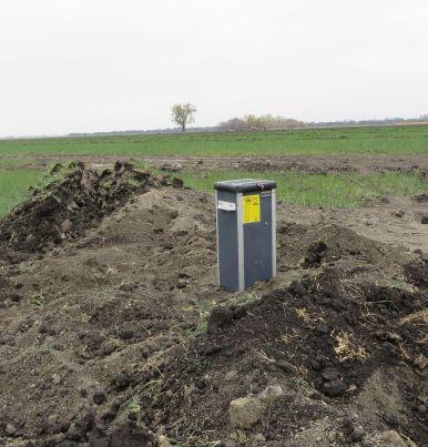
controlled drainage and a third zone with a saturated buffer.
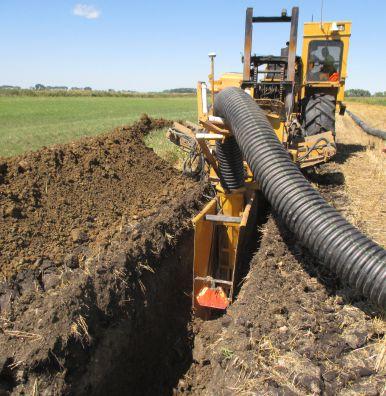
North Dakota’s Tightline Drainage installed the belowground drainage components and structures on both locations in the fall of 2015 so researchers could compare the controlled drainage, conventional subsurface drainage and surface drainage only systems, and document the benefit of a saturated buffer.
“We are encouraging people to do more on this sub-irrigation work but there is no real data if it works or not, so this will give us some real data,” says Myron Tschakert, a sales representative with Tightline Drainage.
Nordick agrees this data will be beneficial to help show these systems work. “Farmers don’t want to spend an extra penny on fertilizer, pesticide or insecticide so it will be good to have
LEFT: Installation of a portion of the main line. Photo courtesy of Jeppe Kjaersgaard.
RIGHT: A control structure after installation.
Photo courtesy of Aaron Janz.
the scientific data to say these are the facts,” he says.
To help get that data, researchers installed systems in the spring to monitor the sites for aspects such as: surface runoff; subsurface drainage flow; rainfall, air temperature and air humidity; soil moisture content and soil temperature; nitrate-nitrogen in surface runoff, subsurface drainage and through the saturated buffer; field management; and the time and management required for controlled drainage.
Jeppe Kjaersgaard, a research scientist with the Minnesota Department of Agriculture who is involved with the project, says they are looking at two different systems – controlled drainage and the saturated buffer – for this research, but “there are other methods out there as well that contractors and producers might want to look into.”
CONTROLLED DRAINAGE
“The way controlled drainage works is putting in a control structure at the outlet of the drainage system so we can adjust the outlet elevation. That way we can hold water back within the root zone during the times of the year where we don’t need to drain water,” Kjaersgaard says. By holding some water back within the root zone in late spring after planting, there is more water available to the crop later in the growing season, which may increase yields. “The idea here is during the fall, after the crop is harvested, we can drain water out, if there is any excess, into ditches and streams when their flow is lower, creating more water holding capacity within the soil for the spring when the risk of flooding is greatest. Without this system, the water drains freely and we are less able to manage when and how much water is leaving the field,” Kjaersgaard says.
“Producers want to keep as much of the nutrients they are adding to their crops on the field as they can and prevent them from getting into the water,” he adds. “Once the nutrients get into our lakes, they can cause algae growth and lead to oxygen removal from the water, which is harmful to fish and aquatic life. Elevated nitrogen concentrations, in the form of nitrate, are also a public health concern.”
Controlled drainage systems are typically installed with new drainage systems and on sites with little slope.
Kjaersgaard says it works best with typically half per cent of slope, but can also be designed for use on sloping terrain. Because the system can also be used for sub-irrigation, the drainage lines are spaced 15 meters apart, which is narrower than the typical spacing of 20 to 25 meters on these soils, Kjaersgaard says.
SATURATED BUFFER
The second method the researchers are looking at is a saturated buffer, which can be retrofitted on an existing system or on more sloping terrain. With this method, a buffer strip of vegetation such as grass, brush or, in some cases, trees, is utilized for the management of water flow and water quality. With the controlled drainage method, the researchers add to the traditionally designed tile system that drains directly into a ditch, stream or other waterway, installing a diversion box in the buffer and running the distribution line parallel to the stream for a distance.
“The idea is, rather than the runoff going directly into the stream, to move it out into the soil in the buffer. The water then moves through the soil towards the ditch,” Kjaersgaard says. He explains buffers of 10 or 20 metres in width are commonly used. “What happens, because the drainage water now is not going into the stream directly, it slows down the movement of the water without changing the efficiency of the drainage system to remove water. That way we can flatten out the peak in runoff amount, which in turn helps with flood mitigation, while maintaining the drainage efficiency.”
Some of the water is also taken up by the vegetation and evaporates from the buffer. As the water moves through
the soil, bacteria remove nitrate and turn it into nitrogen gas that is released harmlessly into the air.
RESEARCH RESULTS
Now that the systems are installed, the researchers collect water samples using automated water samplers and analyze them for nitrate-nitrogen. They also collect meteorological information using an automated weather station located within two miles of the sites, which enables them to calculate crop water use and will help them establish the field water balance. And while they have not yet collected enough data to definitively say how the systems work or what impact they have, there are some early results.
“In the field without tile drains, there is some loss of phosphorus and low nitrogen loss,” Kjaersgaard says. “When we put in subsurface drainage, it switches, so we see a much lower phosphorus loss, but an increase in the nitrate-nitrogen loss.”
This is important knowledge considering it is phosphorus that drives environmental issues like algae blooms in bodies of water such as Lake Winnipeg and Lake Erie. “From an environmental standpoint, putting in drain tile typically reduces the loss of phosphorus compared to surface runoff,” Kjaersgaard says.
Measuring the impact of both phosphorus and nitrogen loss for agriculture is one way this project will help the diverse partners involved meet their objective of demonstrating the water quality and quantity benefits of drainage water management, and to increase the acceptance and adoption of drainage water management in the Red River Valley. DC
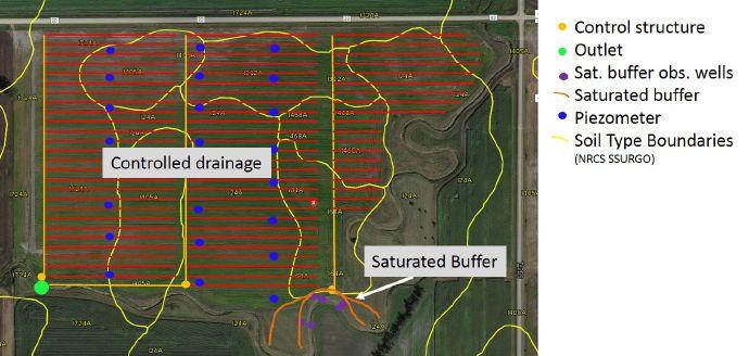
A drawing of Project Site 2, with controlled drainage and a saturated buffer. Image courtesy of Jeppe Kjaersgaard.
Doing the job right
by Sid Vander Veen
Avoid shortcuts when it comes to legal outlets.
Tile drainage is accused of increasing downstream peak flows, causing flooding, moving soil and sediment and making it easy for nutrients to move. Imagine a tile drainage system with no surface inlets. Research has shown it does not increase downstream peak flows; flooding is not increased. The existence of tile drainage encourages infiltration, which reduces overland flow. The reduced overland flow reduces the amount of sediment (topsoil) movement. Recent research suggests there is less phosphorus movement through the tile.
So how does tile drainage get this negative reputation? When surface inlets are added to the tile drainage system, they potentially cause increased peak flows, sediment movement from the surface into the tile drainage system and then into the outlet and movement of nutrients that can attach to soil particles.
In some situations, surface inlets are a necessary component of a tile drainage system, but not in all situations. Staff at the Ontario Ministry of Agriculture, Food and Rural Affairs (OMAFRA) continue to receive complaints about tile drainage systems installed by contractors without a sufficient outlet. After sharing the common law, I also note licensed tile drainage contractors are aware of the need to outlet into locations that don’t do damage to others. I suggest consulting a lawyer to examine their options –licensed contractors should know better.
With the pressure of too much work and not enough time, there may be a temptation to take shortcuts. We have heard about some drainage systems being directed to questionable outlets. The following are not legal outlets:
Roadside ditches: You can only use roadside ditches as an outlet if permission is granted by the road authority. If permission is granted, it is recommended to secure it in writing.
Private ditches: Private ditches located on neighboring properties are private infrastructure and no one has the right to connect a tile drainage
system into them or perform work on the ditch unless permission is given. If your client indicates the neighbor has granted permission, confirm this with the neighbor and ensure permission is in writing. Many contractors have found themselves in the middle of disputes because of differing expectations. If work needs to be done on the neighboring property, make sure all parties are clear on cost-sharing, as well as the extent of work and the potential disruption of land.
Municipal drains: Municipal drains have a defined watershed; the lands within that watershed have paid for the construction and management of that drain and only these lands have the right to connect to the municipal drain. If you are installing tile drainage on a property, it is possible only a portion of that property has the legal right to connect into that drain. Check with the local drainage superintendent before undertaking the work. If there is a section of land outside the limits of the watershed, you must ask for permission to connect those lands to the drain.
Wetland or low area: Sometimes it’s tempting to outlet a tile drainage system into a wetland area, particularly if it is located on your client’s property. However, before doing so, examine the area to determine if the outletting of the tile drainage system could have any impact on other property owners. If it could, don’t install the outlet without first acquiring permission.
If a property owner is unable to secure an outlet, that owner has the right to petition their municipality under the Drainage Act for an outlet. Although it takes longer to get the outlet using the Drainage Act, when it is done, you can have confidence that the tile drainage work you perform will not result in legal action. If you still decide to take shortcuts on legal outlets, remember that the courts consider the tile drainage contractor to be an expert. Be sure to check out the liability risk to you and your business. DC
Surface Water Intakes
• 8” & 10” riser with patented 8" & 10" combination Tees. Also 6” square & round risers with patented reducing Tee.
• Constructed of heavy-weight, high-density polyethylene.
• Parts highly adjustable & interchangeable with others on the market
• Orifice plate placed at tee level or at ground level.
• Exclusive locking device on each part. • User Friendly-Priced effectively.
• Adaptor available to repair old metal or broken intakes.
DC_precision_intake_nov16_MLD.indd 1 2016-10-13 10:04 AM
NEW PRODUCTS
HYDROLUIS DRAINAGE PIPE SYSTEM
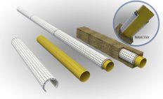
The Hydroluis drainage pipe system, manufactured in Turkey, is the first anti-root drainage pipe. It consists of a corrugated inner pipe with one row of perforations at the top and an unperforated outer pipe that covers approximately twothirds of the inner pipe, leaving the bottom part of the inner pipe in contact with the soil. The pipe saves underground water in drought seasons, and works only when the water table rises above specified levels. www.hydroluis.com.
HOMBURG DYNAMIC DRIVE DRAIN CLEANER
The Homburg Dynamic Drive drain cleaner delivers optimal drain cleaning, ease of use and extended service life. When it detects an obstacle, the feed
is halted and a procedure is initiated to remove the obstacle. Speed is automatically adjusted if increased resistance is encountered. The Dynamic Drive calculates the permissible resistance depending on the length of Homburg HPE hose already fed in. When slippage is detected the feed speed is reduced and eventually stopped, preventing unnecessary wear to the components. The user can input the desired feed distance and once this is reached, the hose is automatically rewound www.homburgholland.com
MAD DOG FOAM BRIDGES
Mad Dog Foam Bridges are made to help complete drain tile repairs along pipeline projects. The bridges are constructed out of lightweight expanded polypropylene. They are designed to attach firmly to the pipeline, and 15 sandbags ensure they stay firmly in place during the backfilling process. No maintenance is required
after installation. The bridges come in sizes ranging from 12 to 42 inches to suit different project needs. Their material is designed to work with current pipeline cathodic protection systems. www.maddogfoambridges.com.
NEW INLET DESIGN FROM HICKENBOTTOM
Hickenbottom Inc. is debuting a design update to its intake line. The new 8 x 5/16 bright orange inlet is specially manufactured to give the installer the ability to make cuts at almost every inch, providing a truly customizable experience in the field, while still retaining the integrity of the product and ease of use to interlock into new or existing Hickenbottom eight-inch drainage set-ups. www.hickenbottominc.com.
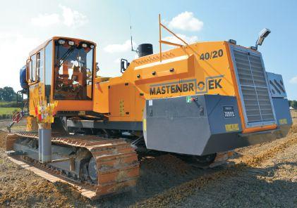
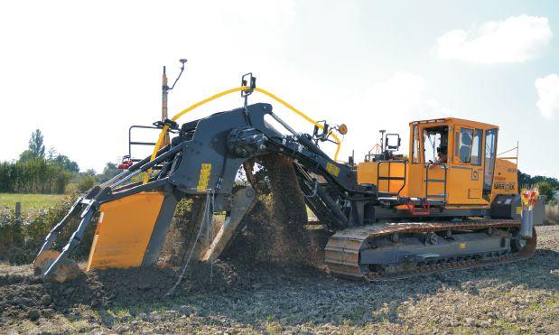
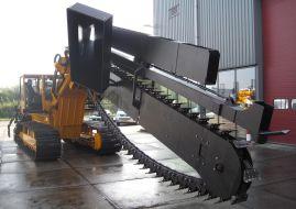
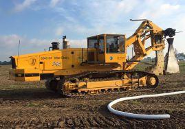
MASTENBROEK LAUNCHES NEW TRENCHER MODEL
British trencher manufacturer
Mastenbroek has released the 40/20 model drainage trencher at 385 horsepower and 70,000 pounds. The digging chain is driven by two heavy-duty hydraulic motors, with selectable low/mid/high speed ranges to suit soil type. With a regular trench depth of eight feet, the digging chain mechanism can be built to suit the customer’s specific requirements for deeper trench depths. Side tilt and extendable track widths aid stability and maximize clearance for spoil from deep trenching. The unit is factory-ready for Trimble GPS depth and autosteer. The operator’s cabin has been developed and is certified to ISO3471:2008 for operator safety. Mastenbroek has developed its range of drainage trenchers and crawler trucks to comply with US EPA Tier 4 Final / EU Stage IV emissions regulations by incorporating Volvo Penta industrial diesel engines. www.mastenbroek.com.
BUSINESS DIRECTORY
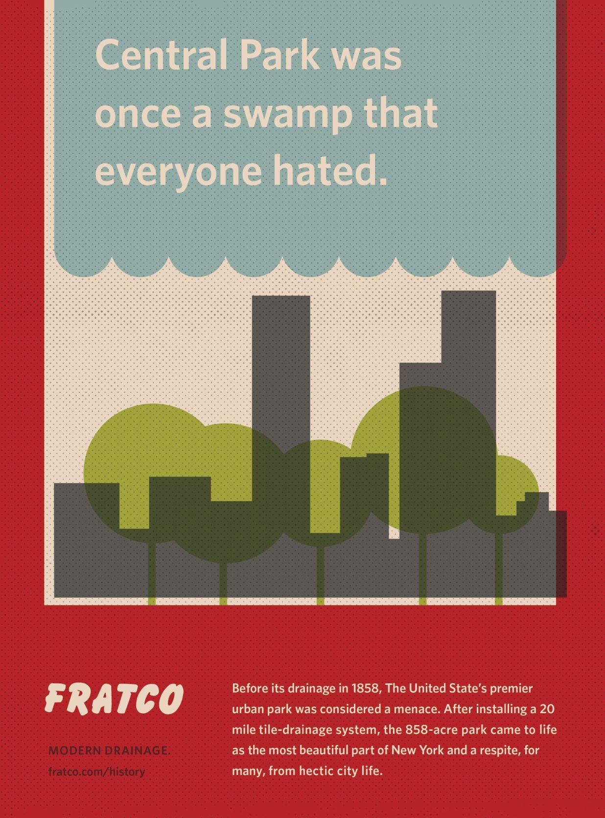
A turning point for drainage?
Britain’s looming exit from the European Union may create opportunities to elevate drainage’s profile in the country’s agricultural policies.
by Rob Burtonshaw
Ifeel like the little boy who cried wolf. In my last column I predicted a reduced workload and belt tightening, but as it happens, we have had just as busy a year as last year. Lesson learnt; from now on you will hear no predictions from me.
Sectors like drainage, which offer long-term investments, prosper in stable and predictable economic conditions.
Obviously on this occasion I’m very happy to be proven wrong. My error was due to being fortunate enough to win a couple of large jobs and the demand for drainage being far more robust than I expected. Despite low wheat prices and average rainfall, growers are still investing in drainage. This is excellent news. Here in the U.K. many farmers are taking soils seriously. For many years this has not been the case, but right now soils are in fashion. The pages of the farming press are full of articles about soil health, cover crops and no-till. With the exception of a sentence or two explaining how important it is, drainage still tends to be overlooked, but this is still an improvement. The more thought and value a farmer places in the soil, the more likely he or she is to think about installing drainage. I’m sure this is feeding the growth in our business and it is most welcome, especially as changes are afoot.
Following the referendum result on June 23, Britain will at some point leave the European Union. What this means is still unknown and, bearing in mind my earlier comments, I will refrain from even the slightest suggestion of a prediction. The change may be minimal or it may be the biggest change in British agriculture since the end of the Second World War. In addition, whilst we know this event
will happen, we have absolutely no idea when it will happen. I’ll be honest: I voted to remain and some of the reasons for my vote were work-related. I think British agriculture had a good (although sometimes maddening) deal in place. The European Union’s Common Agricultural Policy (CAP) took up 40 percent of the EU’s budget and, for all its faults, paid what many could describe as generous subsidies to European farmers. Sectors like drainage, which offer long-term investments, prosper in stable and predictable economic conditions – something the CAP tried and sometimes succeeded in providing. Time will tell if the vote to leave will turn out to be a good decision, but what we have now is an opportunity to influence policy and regulation.
It will be difficult to make our industry’s voice heard. We are a small part of the agricultural sector, which in turn is a small part of the British economy. I’m not entirely sure how we can do it (and maybe we can’t), but the recent interest in soils will, perhaps, offer not just an increase in workload but also an opportunity to leverage that interest into influence on regulation. There is a viewpoint that soils and good soil health are vital not just for successful farming but for the environment. Soil has the potential to act as a store for carbon dioxide. This might be a very useful characteristic. If wet soils prevent or hinder reduced tillage practices, it might provide a successful argument to promote drainage and a favorable regulatory framework. I do not know what will happen, but as always, my answer will be to work hard, put pipe in the ground as efficiently as possible and promote drainage as much as I can. We seem to be living in some interesting times. DC