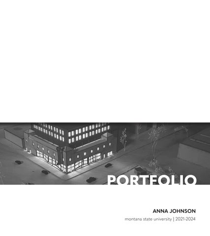
PORTFOLIO
JOHNSON montana state university | 2021-2024
ANNA

ABOUT | anna johnson
My name is Anna Johnson and I am currently pursuing an architecture degree at Montana State University. I grew up in a home that was always changing by the hands of my interior designer mom and “do it yourself” father. Whether I was using architecture plans as a coloring book when I was little, or spending my high school weekends ripping out dry wall, I have been intertwined with design and the built environment my whole life. I am excited to continue to discover my place and learn more about architectural design.
email: annajohnson2002@gmail.com
phone: 720.648.1290
address:
5411 May Fly St. Bozeman, MT 59718
PROJECT 04 | greenhouse work/live...................................................................27-40 CONTENT PROJECT 03 | grande ballroom revitalization......................................................13-26 PROJECT 02 | prosthetics lab...............................................................................05-12 PROJECT 01 | tippet rise art center.....................................................................01-04 PROJECT 05 | story mill center.............................................................................41-50
PROJECT 01
TIPPET RISE ART CENTER | fall 2021
PROJECT OVERVIEW
location: bozeman, mt year of school: second year professor: eric watson
The goal of this project is to provide a Tippet Rise visiting center and art gallery that is accessible to the Bozeman community. In other words, to bring a piece of tippet rise to Bozeman. The form of the building is inspired by the sculptures at Tippet Rise and the forces of the site.
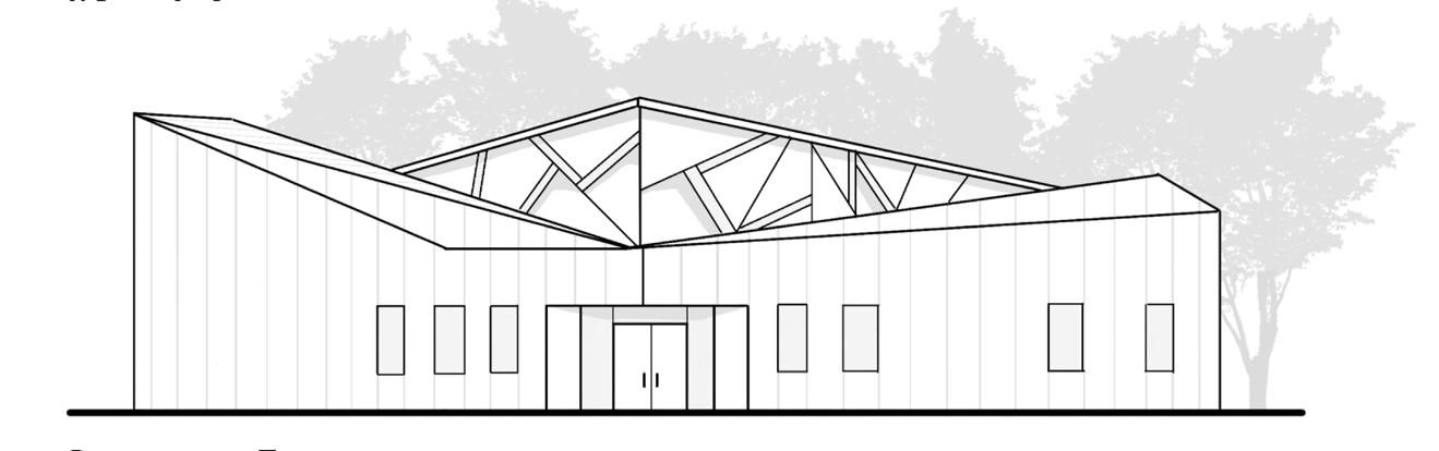
south elevation
northeast elevation
southwest elevation
PARTI DIAGRAM
1) Cut off northeast corner to allow soft northern light into gallery.
2) Continue to break building apart to mimic fractures that are represented in Tippet Rise art pieces.
3) Raise corners of roof to allow southern light into gallery and form fractured roof planes.
project 01 pg 03 tippet rise art center
section aa
project 01 pg 04 tippet rise art center
floor plan
section bb
section cc
PROJECT 02
PROSTHETICS LAB | spring 2022
PROJECT OVERVIEW
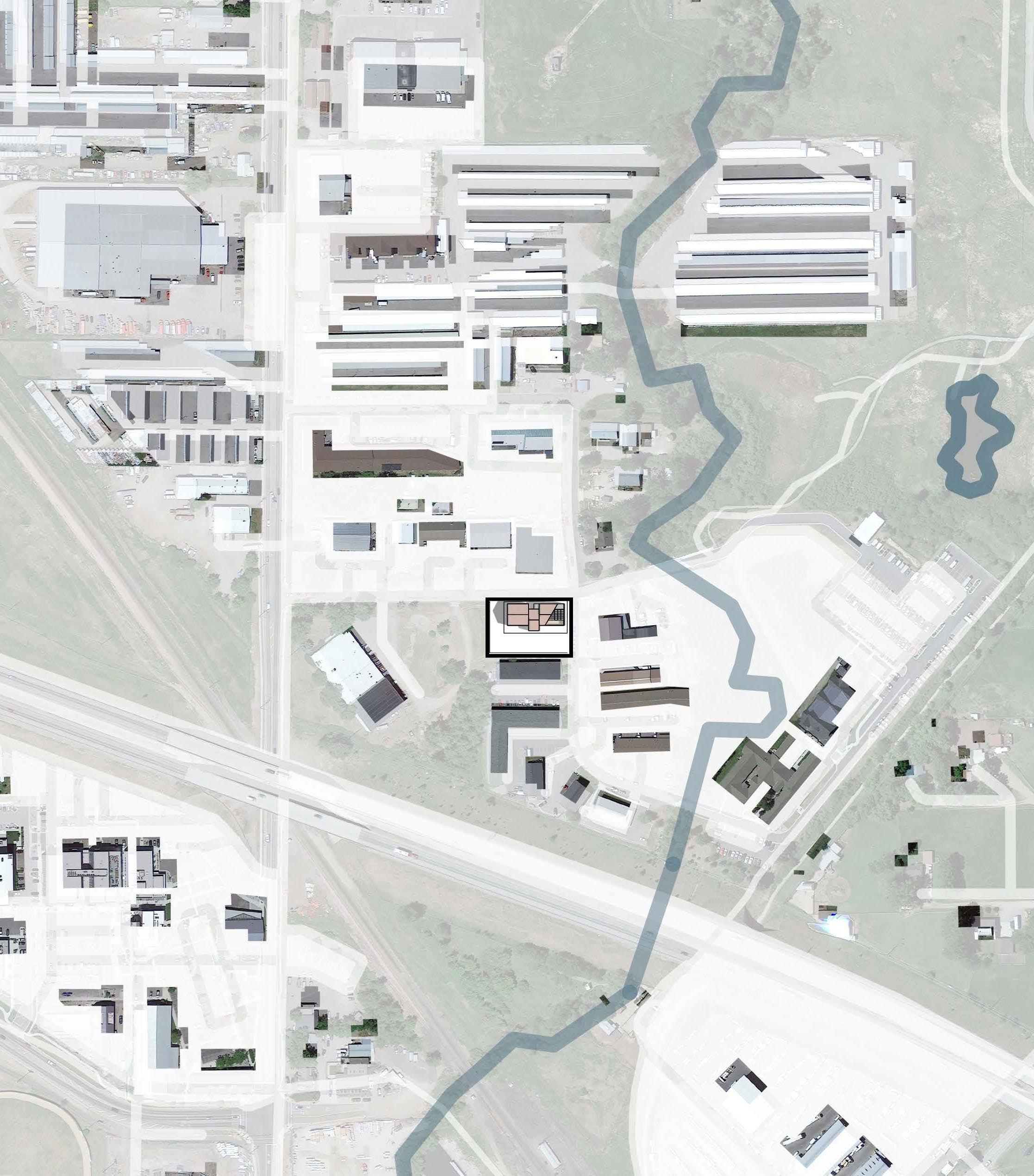
location: bozeman, mt year of school: second year professor: kelly olinger
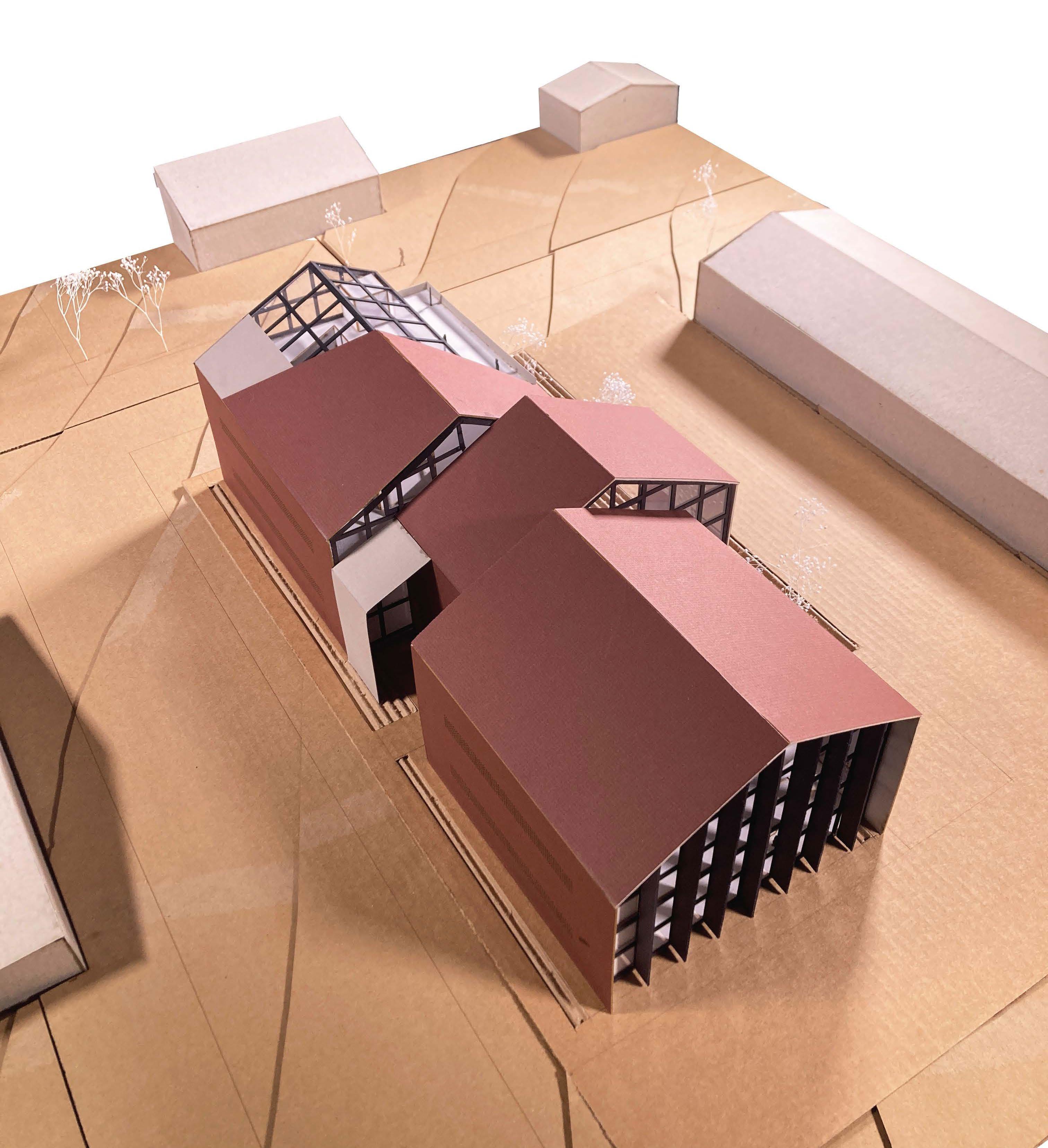
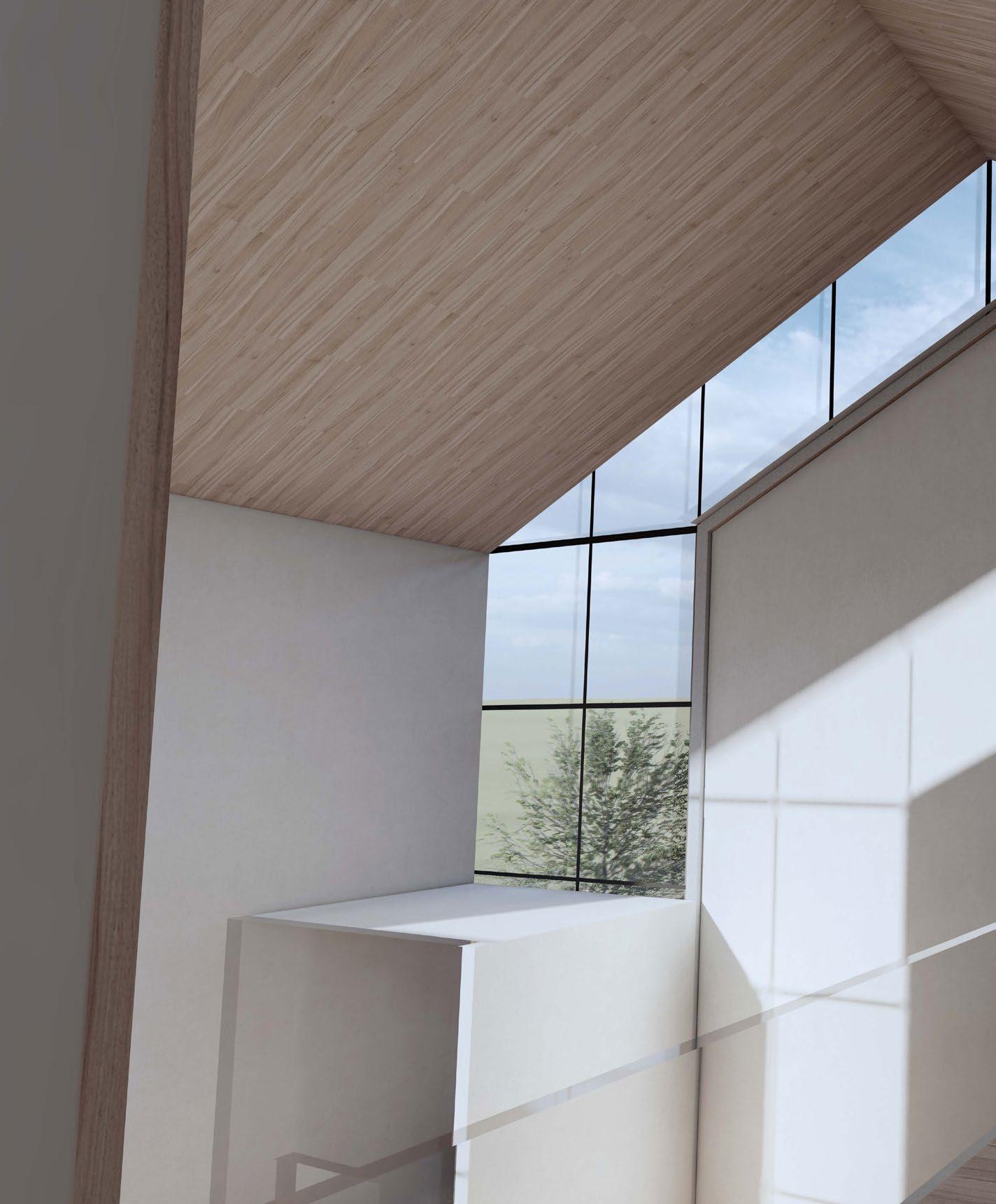
This project provides a space for patients and researchers to collaborate throughout the process of designing prosthetics. The altered gable form explores the differences between function and aesthetics, which is similarly explored in prosthetic development.
I-90 n rouse ave.
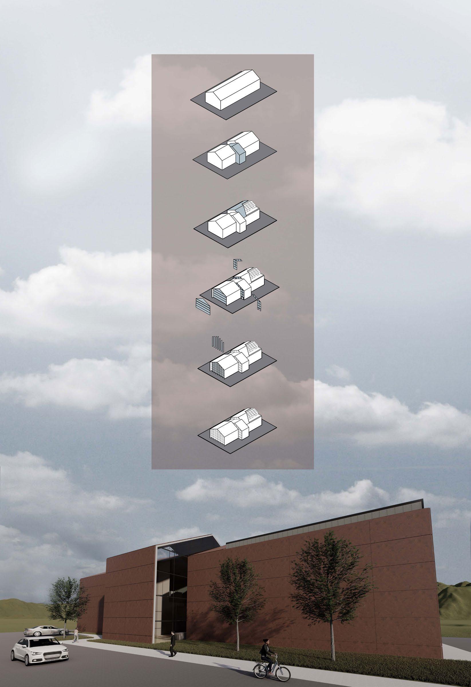
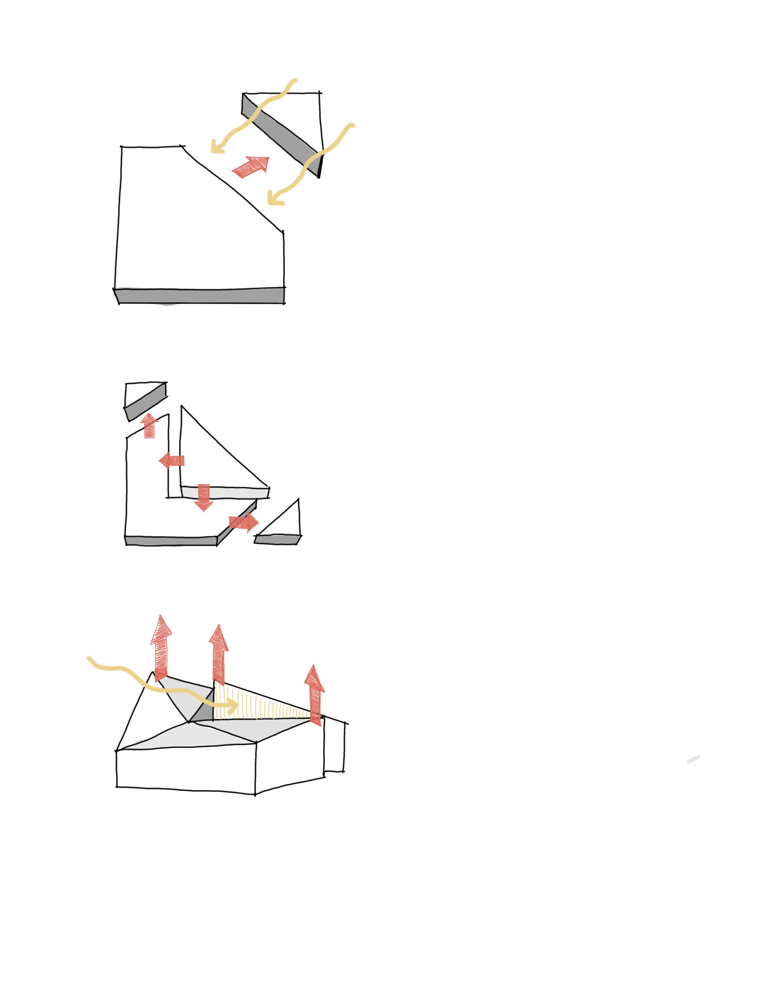
DESIGN PROCESS
I started with a basic gable form as response to the surrounding building typologies. Then I shifted the center of the gable towards the south to highlight both the entry and program. After, I peeled away the functional aspect of the gable form to reveal new forms below. This was in response to studying form vs. function within prosthetics. Then I added glazing to highlight the breaks in the building with louvers. Overall, the shifting and peeling of the gabled form helped me discover how the gable form and function relate to each other. This discovery process will also be reflected in the building program during prosthetic research.
project 02 pg 07 prosthetics lab
project 02 pg 08 prosthetics lab
project 02 pg 09 prosthetics lab
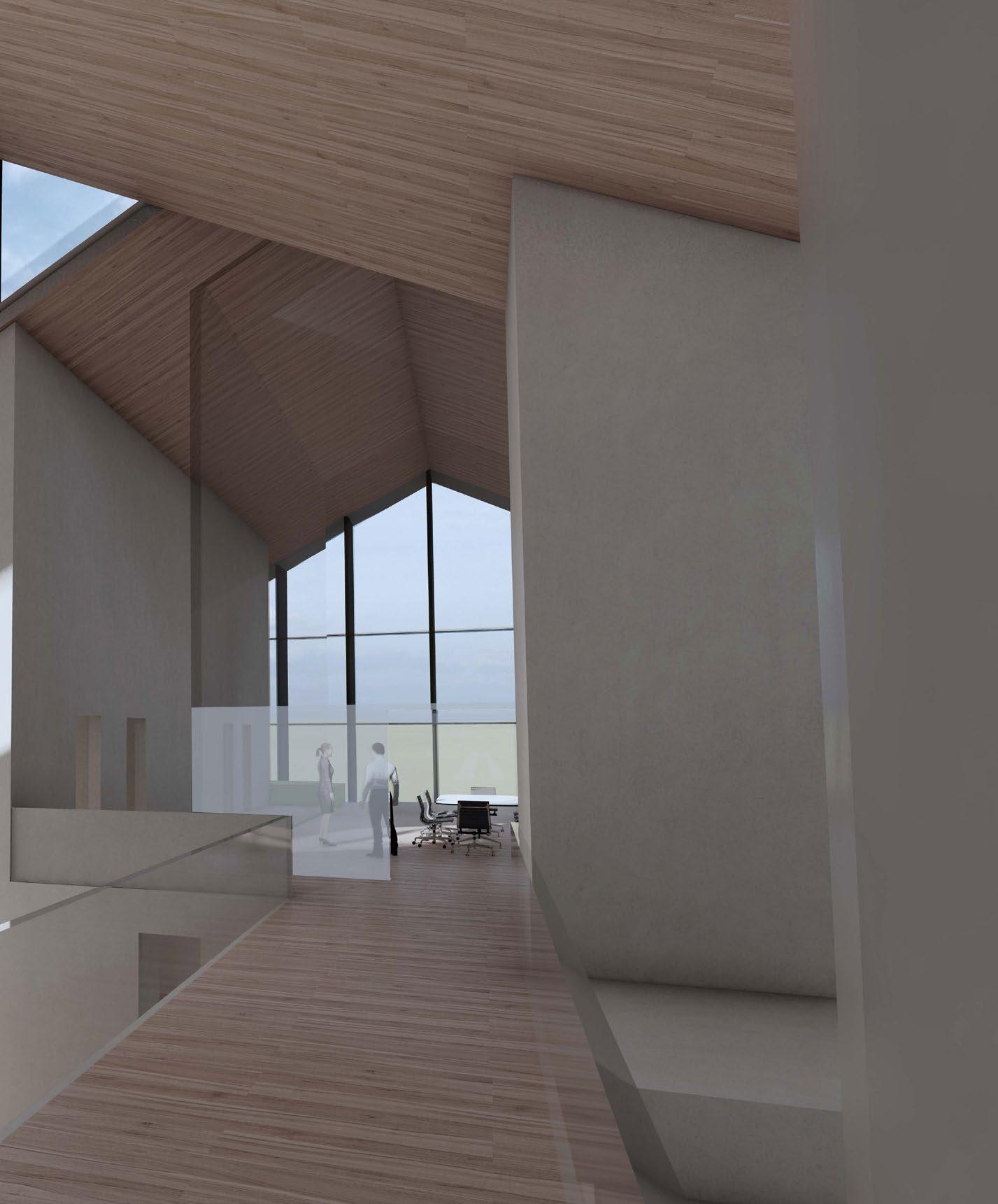
interior rendering standing on 2nd story bridge
project 02 pg 10 prosthetics lab
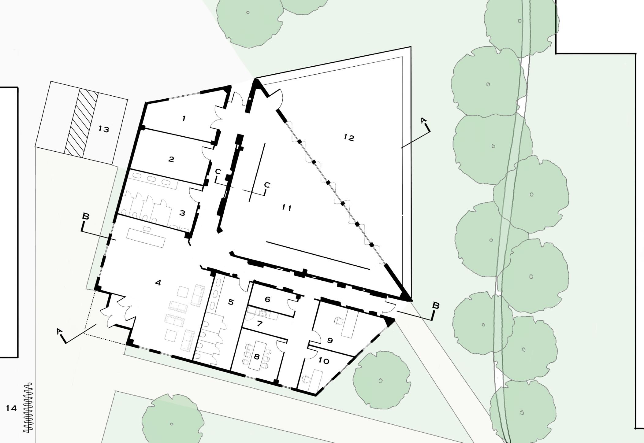
DRAWINGS
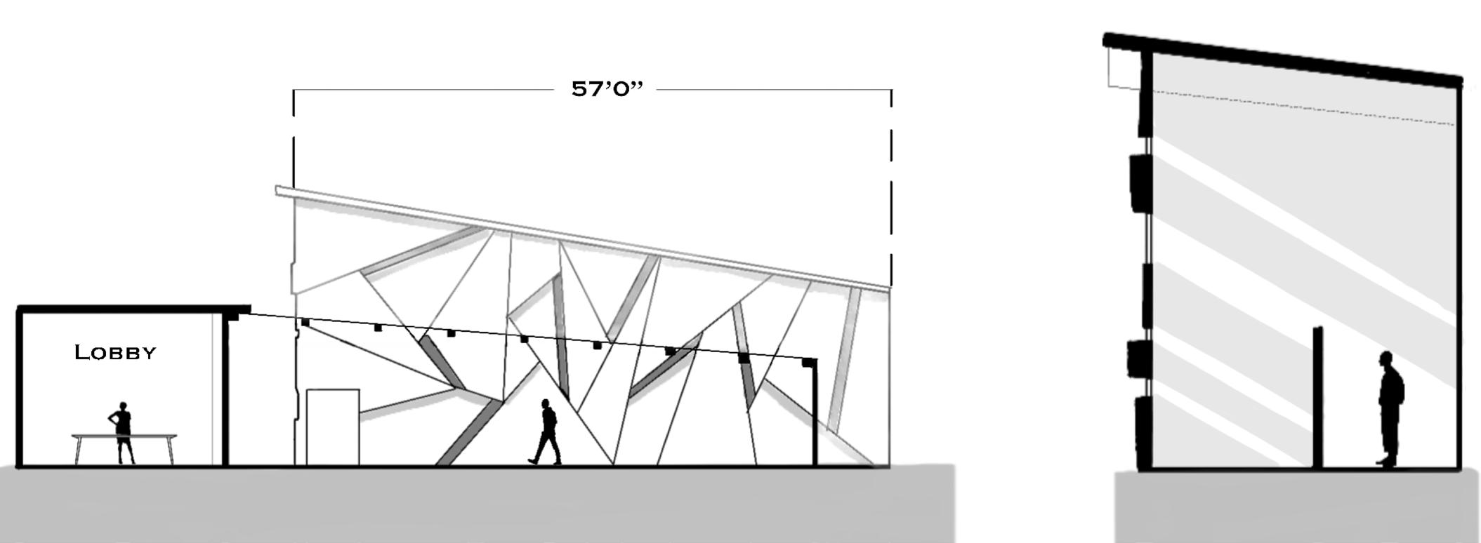
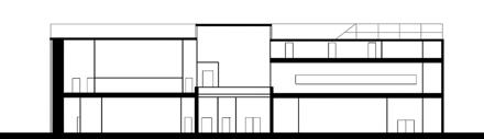
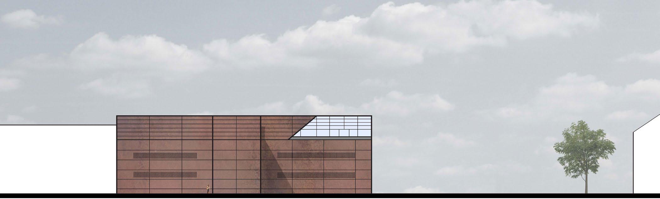
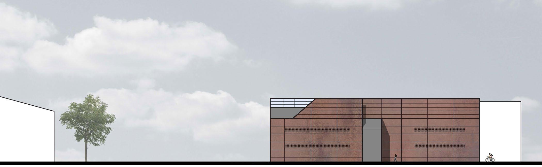
As seen on the elevations below, the exterior of the building is wrapped in corten steel panels. There are perforations throughout the steel to allow light into the rooms that need to remain private. The first floor consists of lobby space in the center, private patient rooms, an area for patient prosthetic testing, and the first level of the research lab. The second level has more lab space, a conference room, and a bridge connecting the two. The central part of the building remains open to the form of the gable roof. Finally, the third level has office space and an outdoor balcony.
project 02 pg 11 prosthetics lab
south elevation
north elevation
project 02 pg 12 prosthetics lab DN DN
A B
level 2 N^ level 3 N^
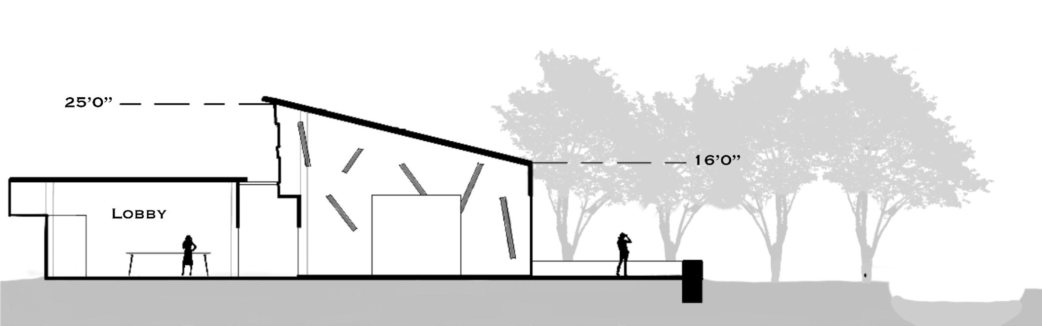
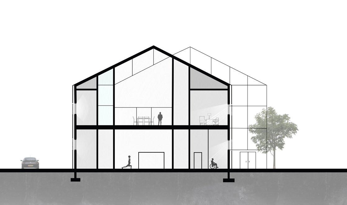
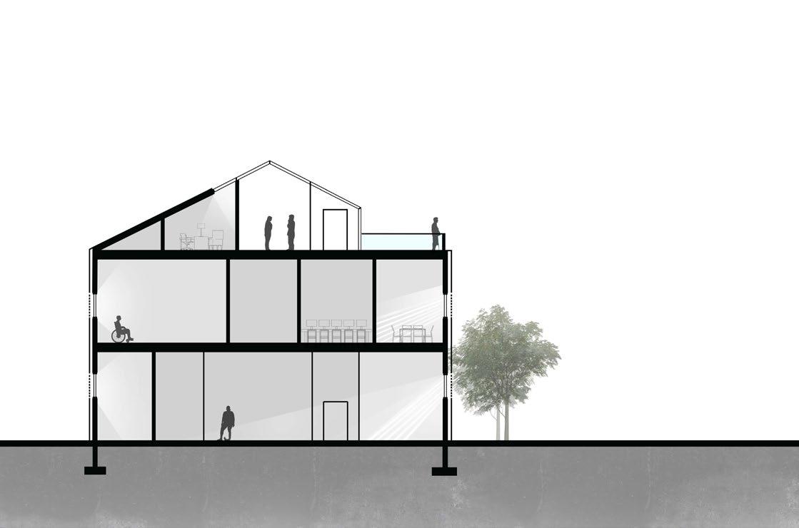
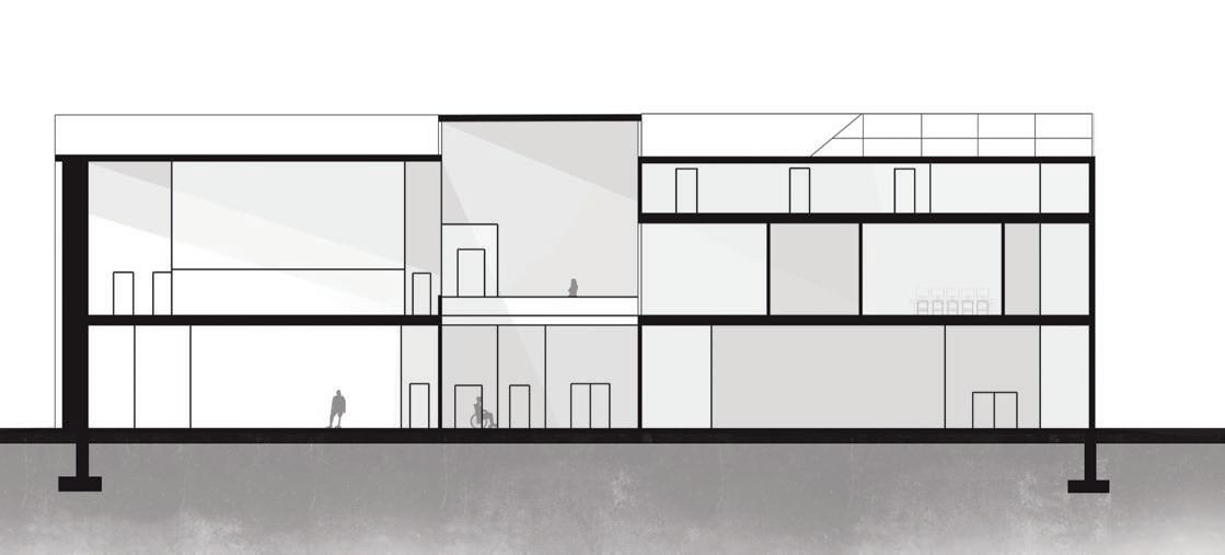
level 1 N^ section c
section b
C
section a
PROJECT 03
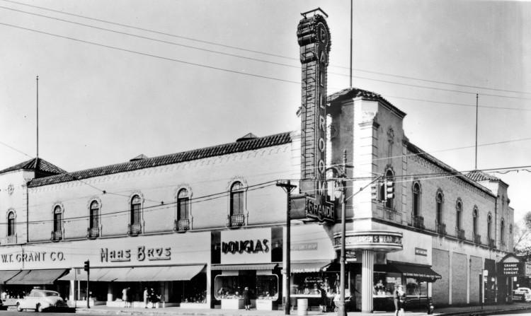
GRANDE BALLROOM REVITALIZATION | fall 2022
PROJECT OVERVIEW
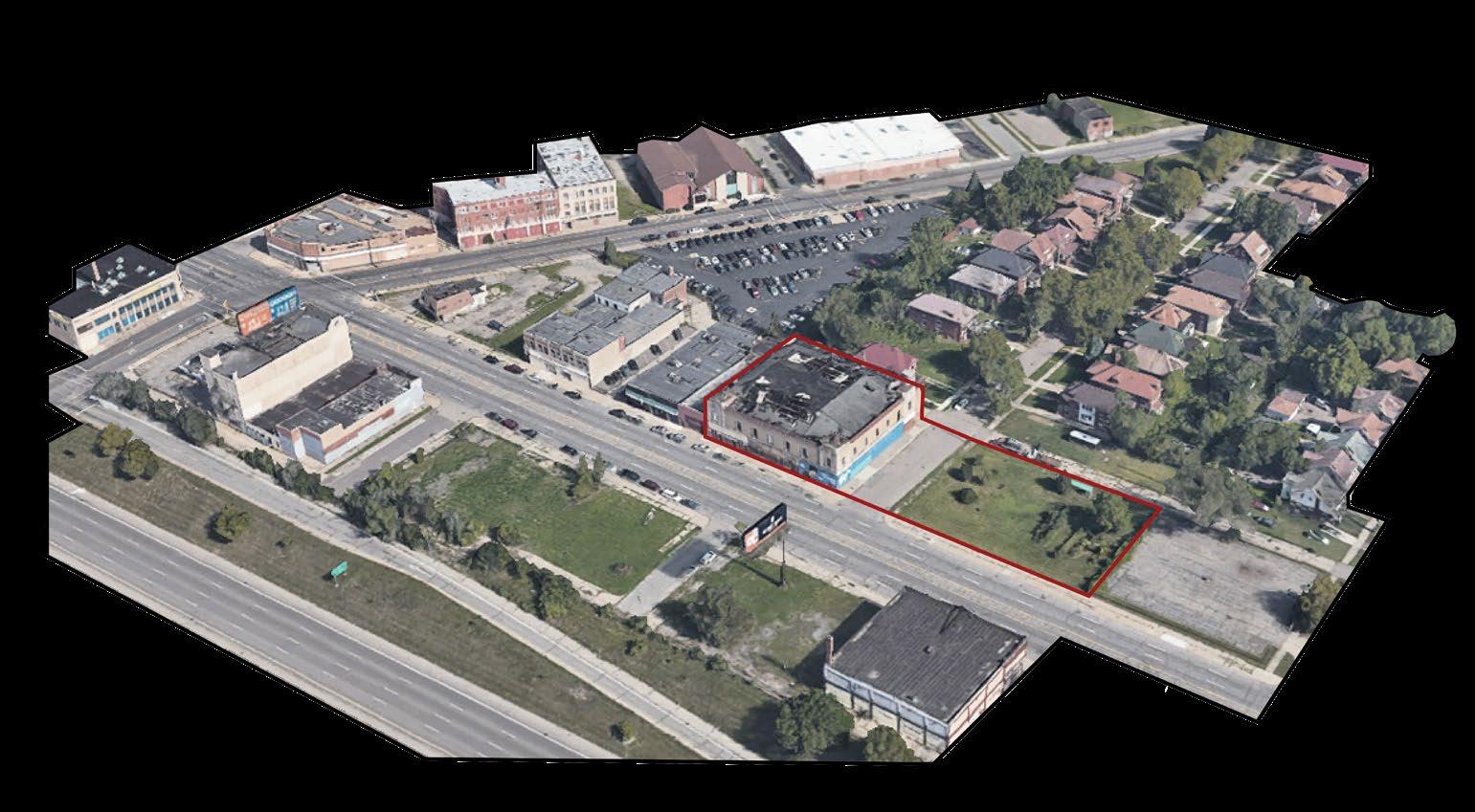
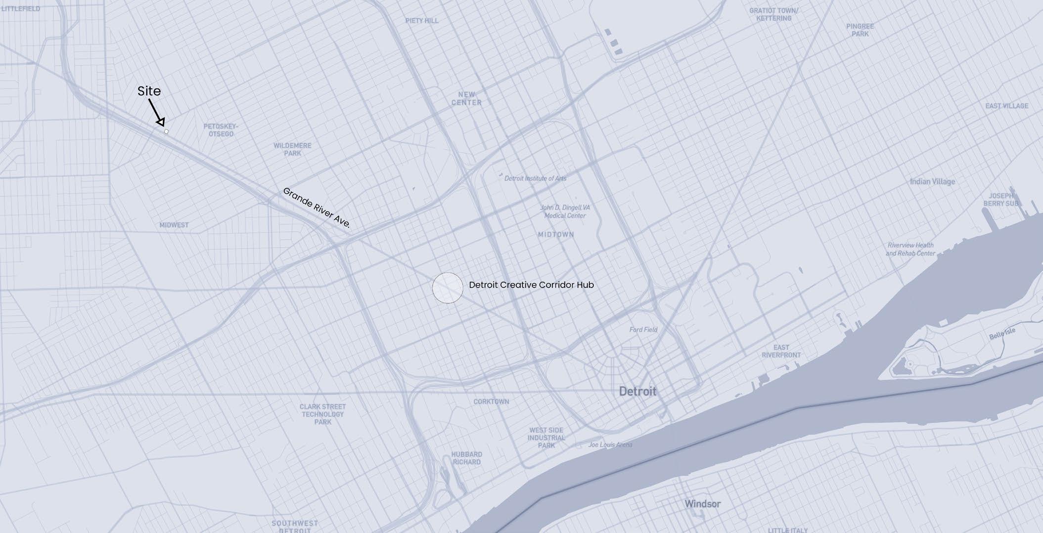
location: detroit, mi
year of school: third year professor: jordan zignego
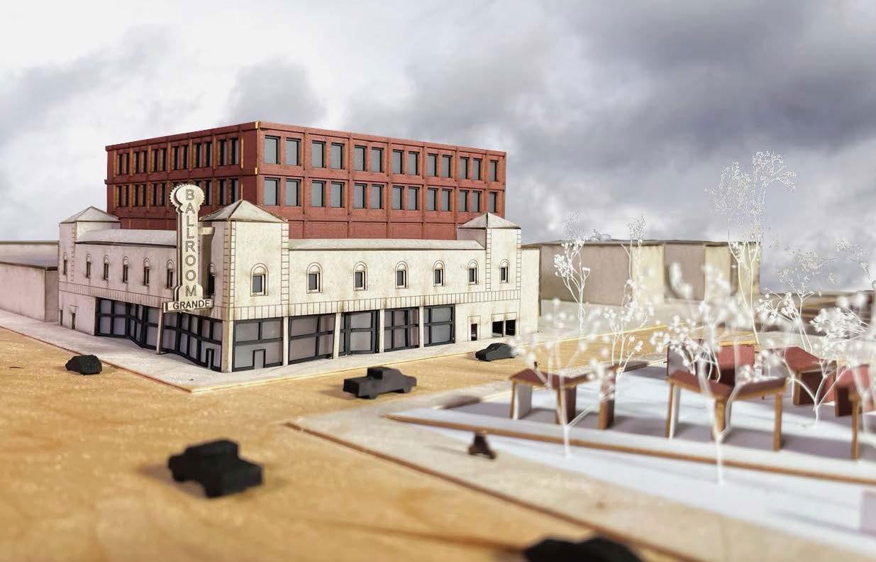
The Grande Ballroom has a rich history. The music at the ballroom been a unifying factor for the Detroit community despite social, race, and class separation and discrimination. This revitalization project consists of a new program in the existing building to serve and unite the community through music as it once did. There is also a residential addition built on top of the existing building.
project 03 pg 15 grande ballroom revitalization
project 03 pg 16 grande ballroom revitalization
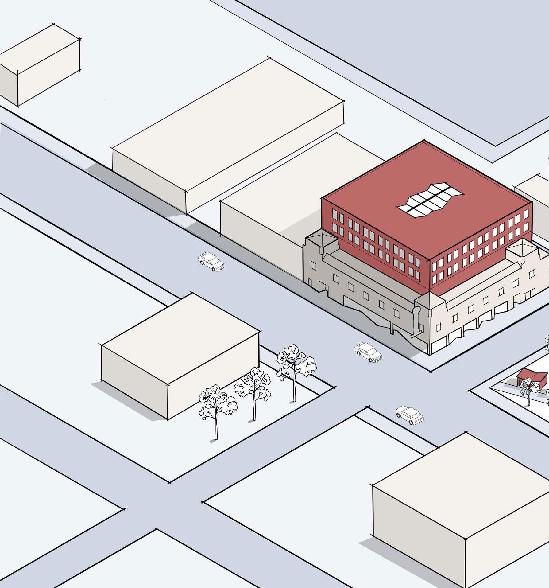
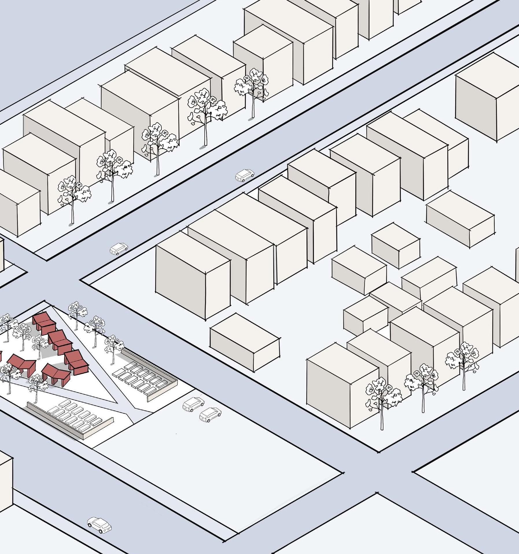
SITE AXON
The site axonometric shows the relationship between the Grande Ballroom and the community park/garden design. The shelters act as water collectors as well as canvases for local graffiti artists. Furthermore, I maintain the planter boxes to preserve the existing community program.
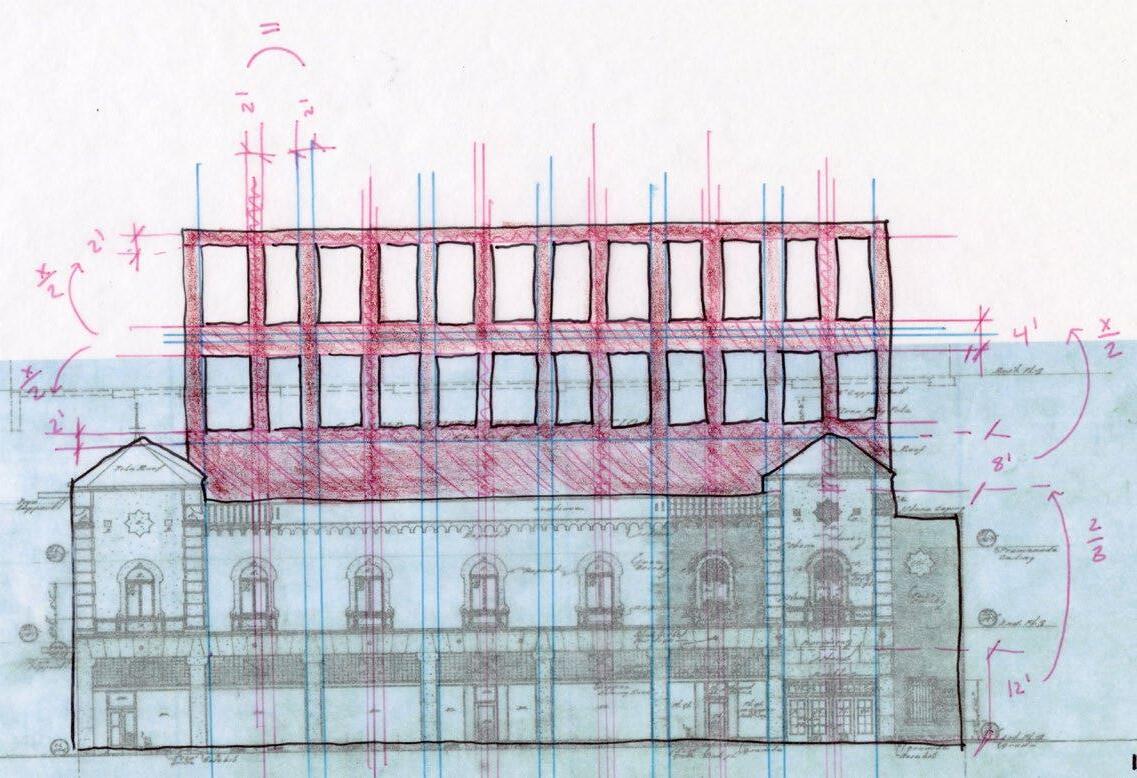
PROPORTION STUDY
In order to make an appropriate and respectful addition to the top of the historic Grande ballroom, I studied three iterations of the addition. I started by drawing primary lines that come from the original construction. From there, I constructed 3 unique elevations that respond to the original building rhythms. In the end, I chose iteration 3, as it is well balanced and does not over power the building below.
project 03 pg 17 grande ballroom revitalization

iteration one
iteration two
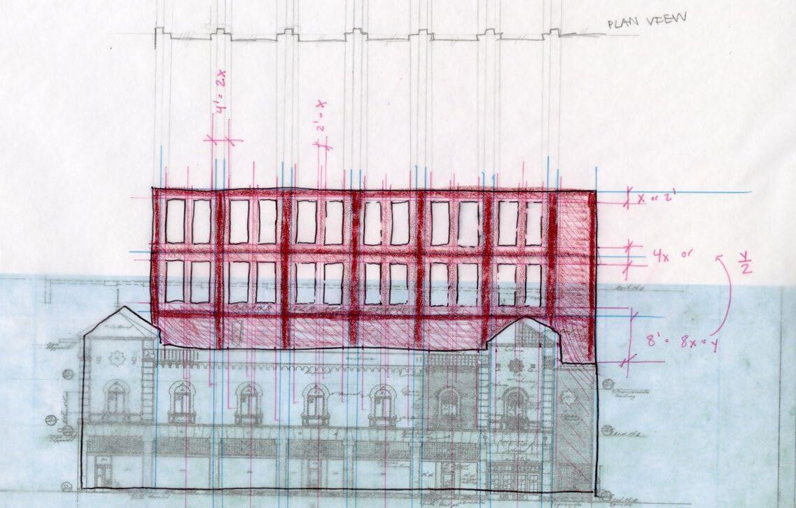
iteration three
project 04
pg 18 grande ballroom revitalization
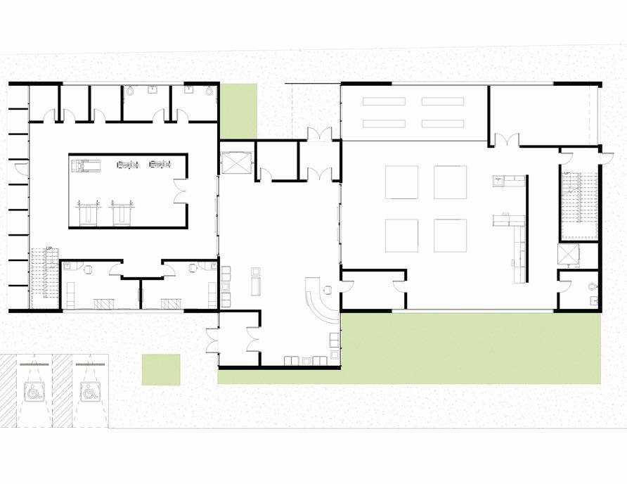
FLOOR PLANS
The first floor consists of exhibit space to display local the history of the Grande and recording studios. The second floor is a small restaurant and concert venue to honor the original music venue program. The third an fourth floor are apartment units. The blue areas of the floor plan indicate where the regularity of the walls is broken. This irregularity was inspired by architectural strategies for recording music.
level one
level two
pg 19 project 03 grande ballroom revitalization UP UP UP UP 132 SF ISO Room 133 SF ISO Room 132 SF Storage 390 SF Control Room 283 SF Recording Studio 336 SF Control Room 277 SF Men's Bathroom 366 SF Mech. Room 279 SF Women's Bathroom 1141 SF Artist's Lounge 326 SF Recording Studio 1246 SF Atrium 755 SF Residential Lobby 2643 SF Gallery 201 SF Ticket Office 81 SF Storage A A UP DN DN DN UP 469 SF Private Studio 428 SF Private Studio 528 SF Private Studio 1334 SF Collaboration Studio 1582 SF Kitchen 527 SF Backstage 233 SF Men's Bathroom 224 SF Women's Bathroom 5593 SF Restaurant 233 SF Original Stage 51 SF Mech. 1291 SF Waiting Room 225 SF Storage
project 03 grande ballroom revitalization pg 20 DN UP 144 SF Mechanical 129 SF Mechanical 988 SF 2 Bed 1000 SF 2 Bed 832 SF 1 Bed 749 SF 1 Bed 730 SF 1 Bed 1079 SF 2 Bed 889 SF 1 Bed DN UP 144 SF Mechanical 129 SF Mechanical 988 SF 2 Bed 1000 SF 2 Bed 832 SF 1 Bed 749 SF 1 Bed 730 SF 1 Bed 1079 SF 2 Bed 889 SF 1 Bed
level three
level four
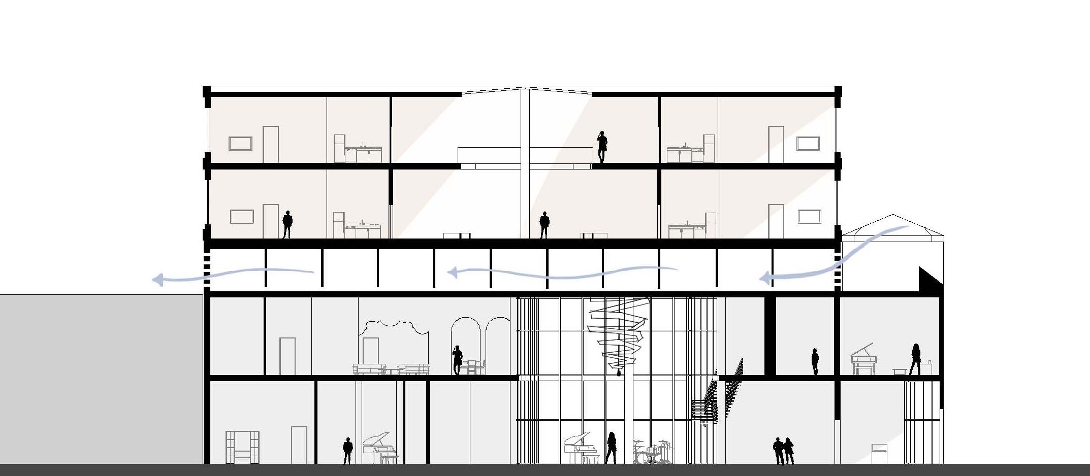
ACOUSTIC STRATEGIES AND BUILDING SECTION
The architectural acoustic strategies to the left are not only used for music production, but they also influence the architectural language the building. The use of irregular wall angles is best shown in the floor plans on the previous page. The use of atrium is best seen in the building section below. Furthermore, the structural system that supports the residential addition creates a intermediate space for mechanical systems that are naturally ventilated through openings in the brick pattern.
grande ballroom revitalization project 03 pg 21
section a
existing adjacent building
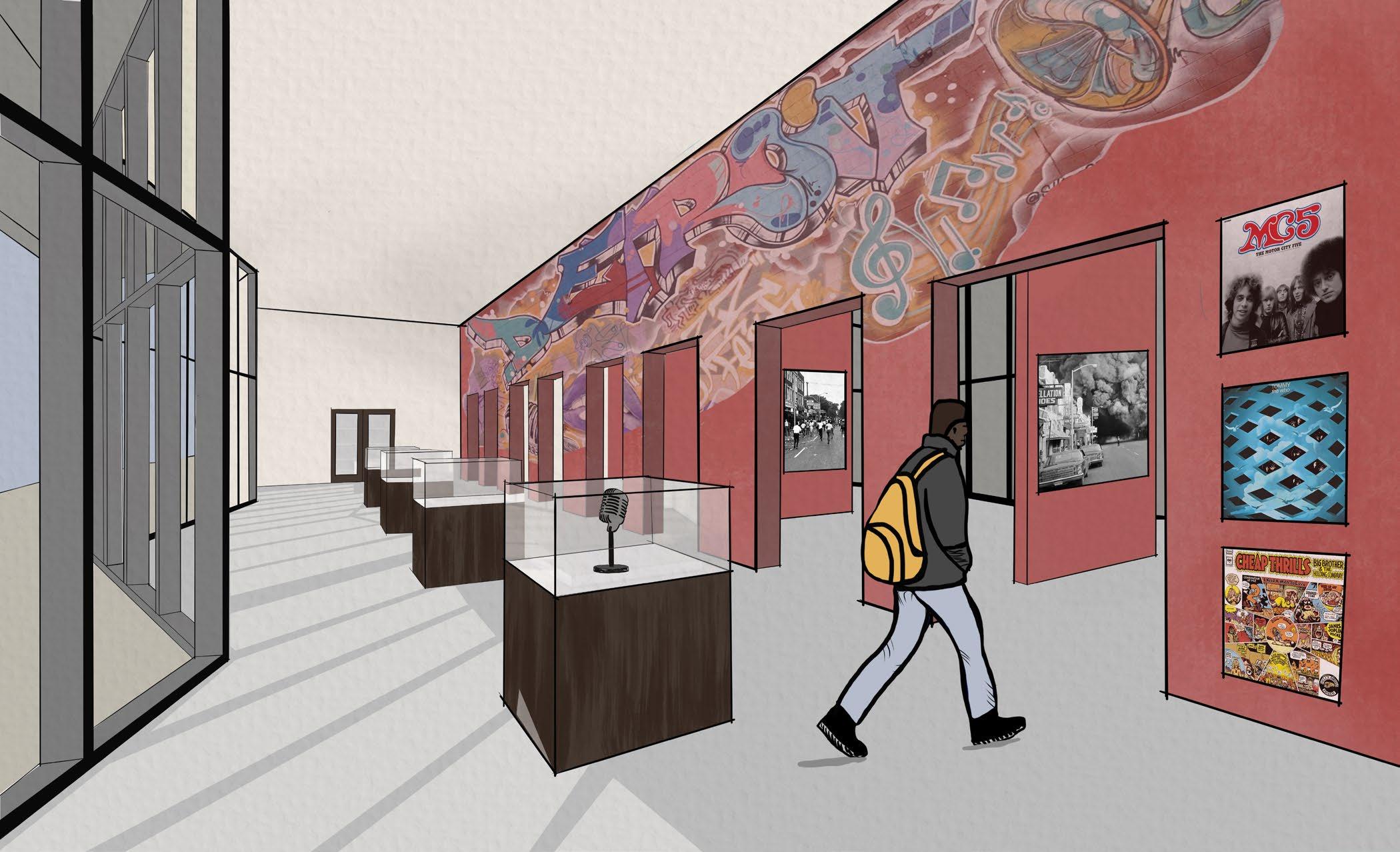
INTERIOR SPACE
The brick addition on the interior of the first floor visually ties the residential addition on top of the building to the ground floor. It also provides opportunity to display the history of the Grande as well as local artists to display their work.
project 03 grande ballroom revitalization pg 22

project 03 grande ballroom revitalization pg 23
residential wall section
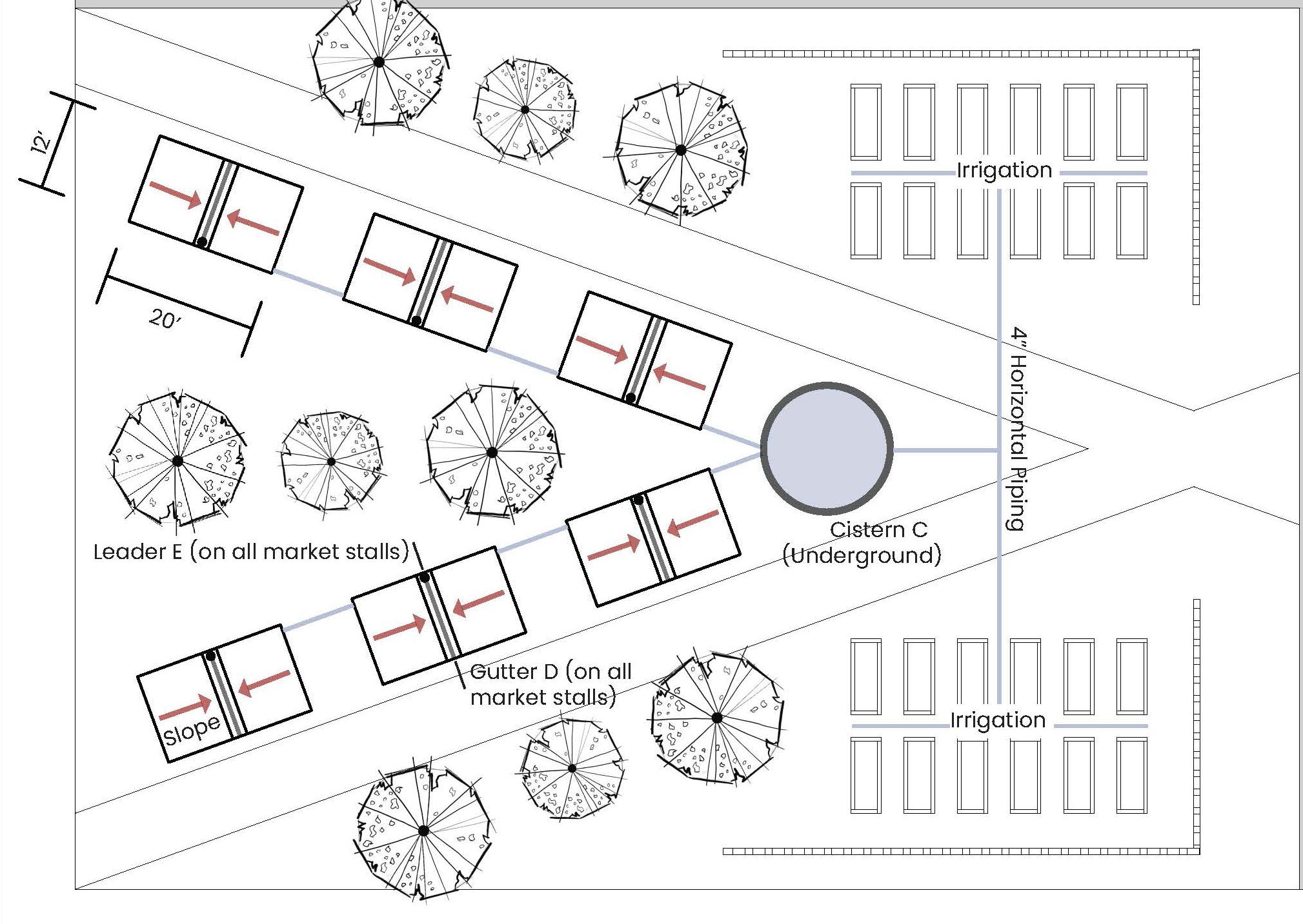


The existing park has rain water collection system. The community surrounding the Grande uses this to fuel their current urban garden. Therefore, the implementation of a new system will enhance the community’s use of the park. The rainwater collectors act as shelter and canvas for local artist to display their work.
grande ballroom revitalization project 03 pg 24
COMMUNITY PARK
PROJECT 04
GREENHOUSE WORK/LIVE | spring 2023
PROJECT OVERVIEW
location: bozeman, mt
year of school: third year
professor: barry newton
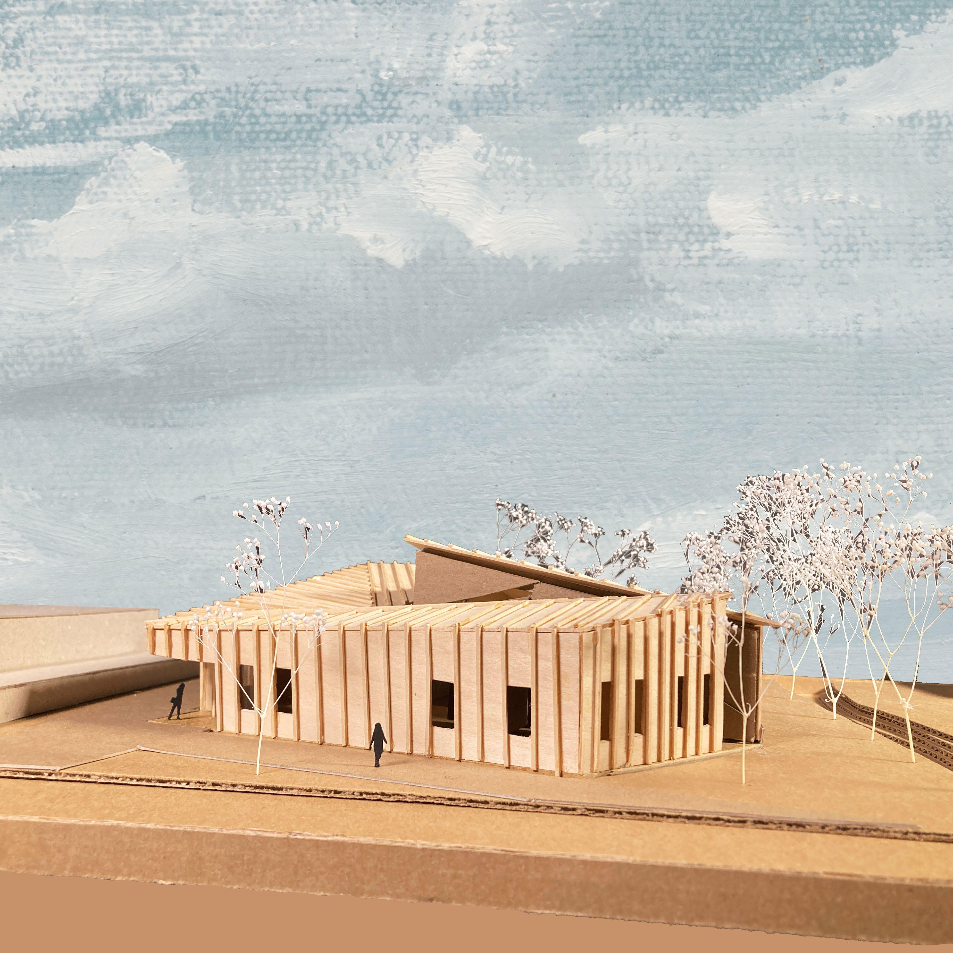
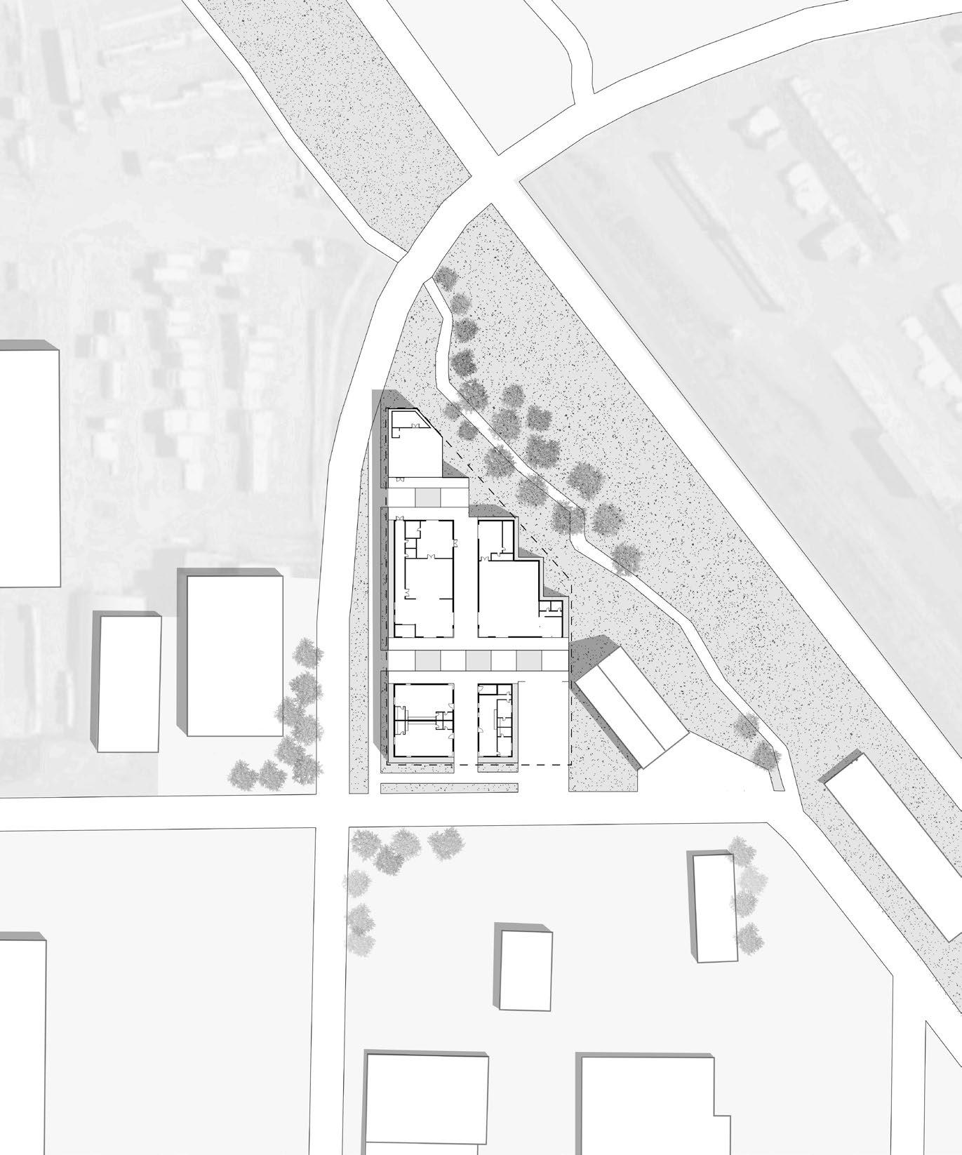
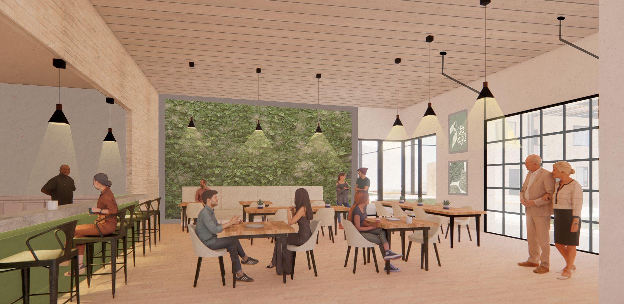
This live/work community project integrates and makes clean and sustainable food production accessible to both the live-in residents and the surrounding communities. It features an overhead greenhouse with a restaurant, grocery store, and apartment units.
n wallace ave
st traintracks
e tamarack
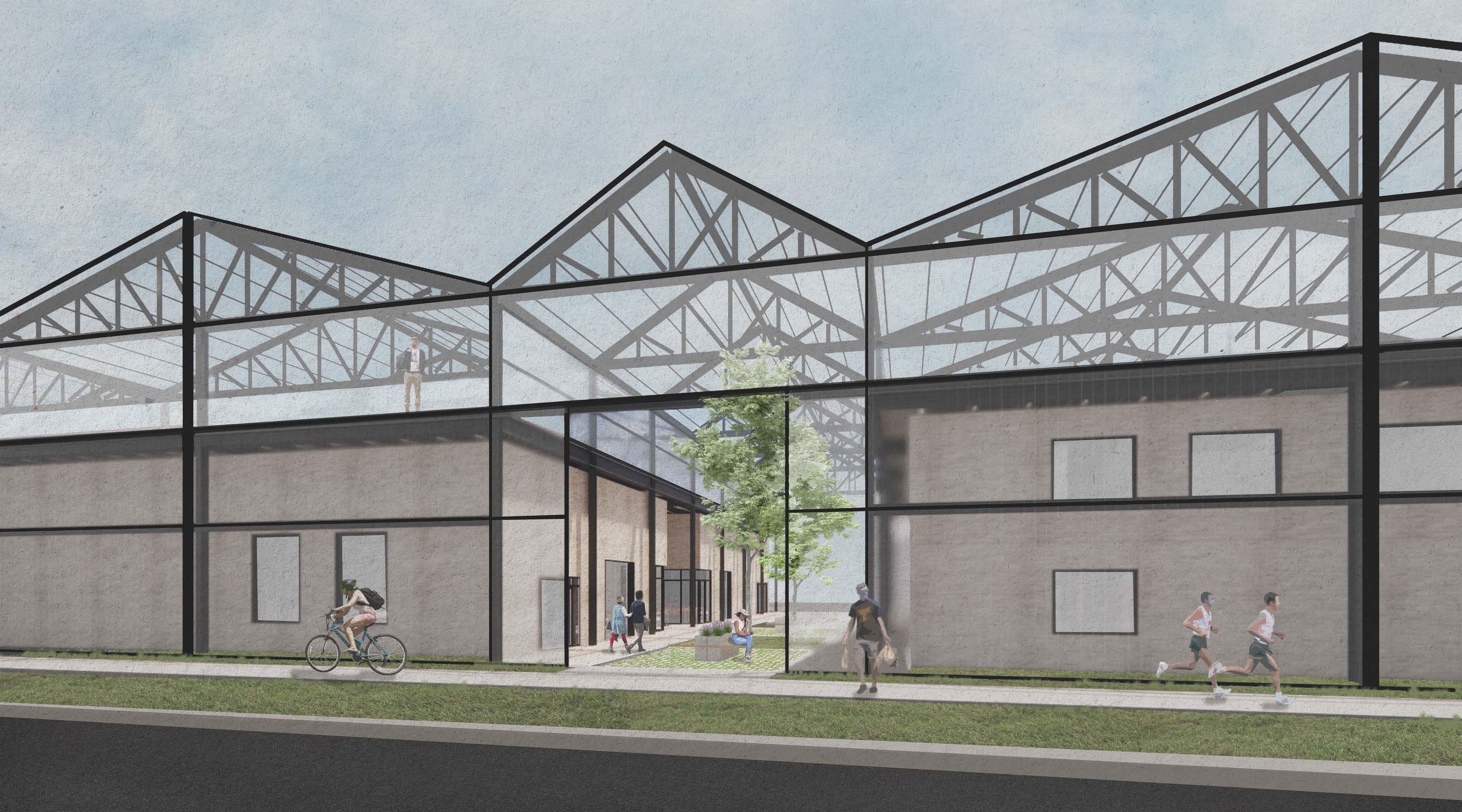 street view
FLOOR PLANS
The site for this project has a very unique property line (as seen in the previous site plan). This was one of the primary influences on the shape of the building. The ground level contains apartments, grocery store, cafe, and the first level of a hydroponic farm. The second level has more apartment units, and there is a greenhouse over head. There are openings throughout the greenhouse perimeter to promote circulation from the surrounding community.
project 04 pg 29 greenhouse work/live 1 2 3 4 5 6 7 8 9 10 A B C D E F G H UP level one
project 04 pg 30 greenhouse work/live 1 2 3 4 5 6 7 8 9 10 A B C D E F G H UP
level two level three (greenhouse)
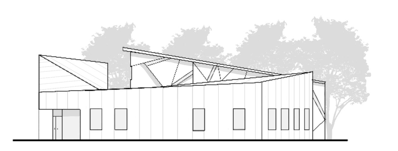
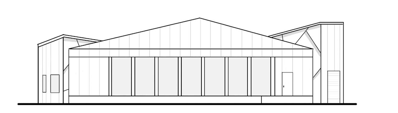
SECTIONS & ELEVATIONS
The sections and elevations show the relationship between the overhead greenhouse and the program below. The gabled roofs are at the optimal angle for sunlight into the greenhouse, and they also act as rainwater collectors.
project 04 pg 31 greenhouse work/live
east elevation
building section
project 04 pg 32 greenhouse work/live
pg 33 greenhouse work/live project 04
south elevation
building section
pg 34 greenhouse work/live project 04
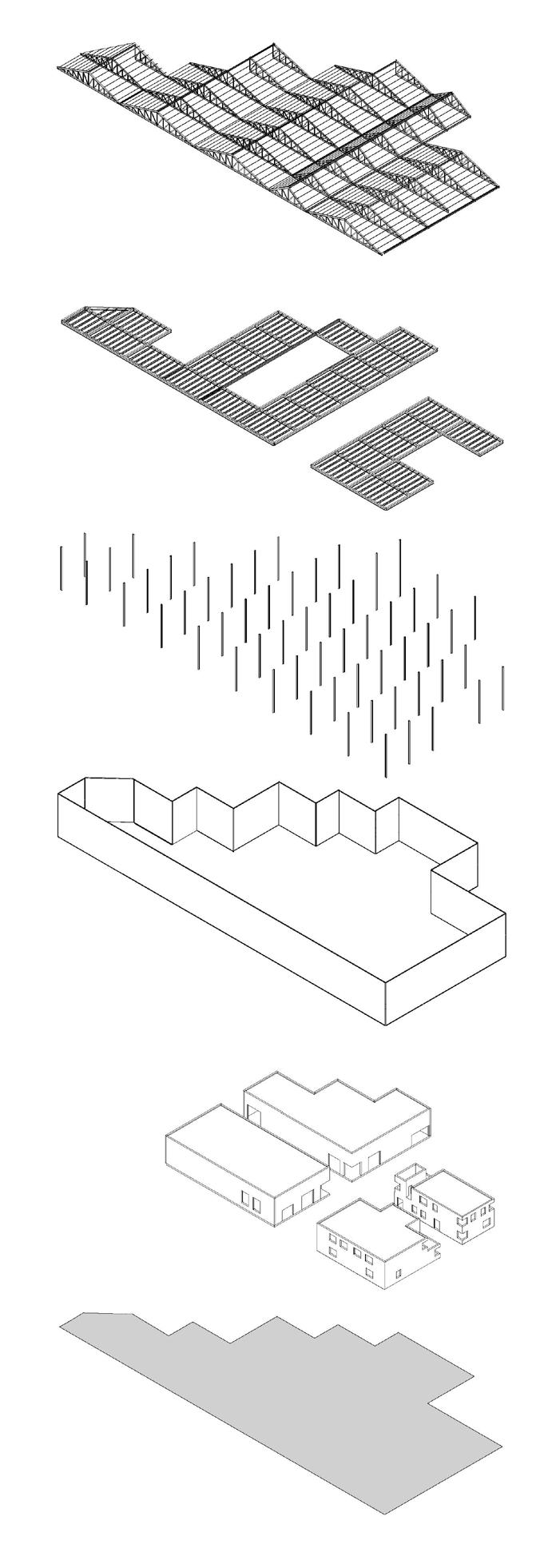
STRUCTURAL DIAGRAM
The structural digram helps communicate how the greenhouse is a shell that protects and surrounds the interior program.
project 04 pg 35 greenhouse work/live

project 04 pg 36 greenhouse work/live
Solar energy collected in PV panels is used to power artificial lighting for hydroponic farm
Rainwater and snow melt collected from roof slopes
Water stored and used for crops growing in greenhouse
Water heating/cooling in
pg 37 greenhouse work/live project 04
Polycarbonate panels and roof panels help transmit the most amount of light and eliminate harmful UV
Water can also be used to aid in the heating/cooling of excess heat generated in greenhouse
Excess heat can be redirected and recirculated
Heating for building in the winter
Cool air for greenhouse circulation and building air conditioning
SUSTAINABLE STRATEGIES
This section diagram demonstrates how the greenhouse and the main level program work together to create a sustainable building system.
greenhouse work/live pg 38 project 04
PROJECT 05
STORY MILL VISITORS CENTER | spring 2023
PROJECT OVERVIEW
location: bozeman, mt
year of school: third year professor: eric watson (building construction and environmental control systems) partner: tim ottey
The objective of this project was to generate a comprehensive set of construction documents, enhancing our proficiency in Revit, drawing sets, and gaining insights into mechanical, electrical, and structural systems. Initially designed by another student, the building design was passed on to my partner and I, challenging us to produce a construction drawing set for the building.
4709'- 0" 4712'0" Existing Building Existing River Roof Overhang E. Griffin Drive
SWR SWR SWR SWR SWR SWR SWR SWR SWR SWR SWR SWR SWR SWR SWR WTR WTR WTR WTR WTR WTR WTR RTW RTW RTW RTW W PWR PWR PWR PWR PWR PWR PWR PWR PWR
4715'0" 4716'0" 4717'0" 4718'0" 47190" 4720'0" 4722 -0" 4723 -0" 4721'0" Snow Storage N 899' - 5 3/32" E 348' - 8 7/32" New Pavement New Sidewalk New Boardwalk FFE = 100'-0" New Trees L Street EL: 4,720'-0" 177' - 0" 165'0" Transformer Box
PWR
PLANS AND SECTIONS
This building was deigned on a platform, elevating the building from the ground. A boardwalk connects the building to both sides of the open space in Story Mill Park. The second level of the building is a small private reading room. We were also tasked with creating overall sections as well as detailed wall sections to demonstrate our understanding of the building envelope.
project 05 pg 43 story mill visitors center 11 B A C Assembly Hall 9 Bathroom 11 Bathroom 12 Library 3 Mech 4 Bathroom 5 Bathroom 6 Lobby 1 Mech 8 Vestibule 7 Storage 2 Storage 10 D 12 13 14 15 16 17 18 19 20 A2.3 3 10 9 8 7 6 5 4 3 2 A6.1 4 1 A4.1 1 A4.1 2 A4.1 2 A4.1 10' 0" 10' 0" 10' 0" 10' 0" 10' 0" 10' 0" 10' 0" 10' 0" 20' 2 7/16" 10' 0" 10' 0" 10' 0" 10' 0" 10' 0" 10' 0" 10' - 0" 10' 0" 10' - 0" 18' 0" 7' 7" 18' 0" 5' 8" 15' - 0" 20' - 0" 20' - 0" 20' - 0" 15' - 0 1/4" 15' 0" 4' 8" 5' 0" 4' 8" 25' 0" 20' 0" 11 B A C D 12 13 14 15 16 17 18 19 20 10 9 8 7 6 5 4 3 2 1 1 A4.1 1 A4.1 2 A4.1 2 A4.1 Reading Room 14 10' 0" 6' 0" Scale DATE DRAWN 1/8" = 1'-0" 1 Level 1 1/8" = 1'-0" 2 Level 2 0' 4'8'16' 32' 0' 4'8'16' 32' No.DescriptionDate 1 Client: 11 B A C Assembly Hall 9 Bathroom 11 Bathroom 12 Library 3 Mech 4 Bathroom 5 Bathroom 6 Lobby 1 Mech 8 Vestibule 7 Storage 2 Storage 10 D 12 13 14 15 16 17 18 19 20 A2.3 3 10 9 8 7 6 5 4 3 2 A6.1 4 1 A4.1 1 A4.1 2 A4.1 2 A4.1 10' 0" 10' 0" 10' 0" 10' 0" 10' 0" 10' 0" 10' 0" 10' 0" 20' 2 7/16" 10' 0" 10' 0" 10' 0" 10' 0" 10' 0" 10' 0" 10' - 0" 10' 0" 10' - 0" 18'0" 7' 7" 18'0" 5' 8" 15' - 0" 20' - 0" 20' - 0" 20' - 0" 15' - 0 1/4" 15' 0" 4' 8" 5' 0" 4' 8" 25' 0" 20' 0" 11 B A C D 12 13 14 15 16 17 18 19 20 10 9 8 7 6 5 4 3 2 1 1 A4.1 1 A4.1 2 A4.1 2 A4.1 Reading Room 14 10' 0" 6' 0" Scale DATE DRAWN 1/8" = 1'-0" 1 Level 1 1/8" = 1'-0" 2 Level 2 0' 4'8'16' 32' 0' 4'8'16' 32' No.DescriptionDate 1 Client:


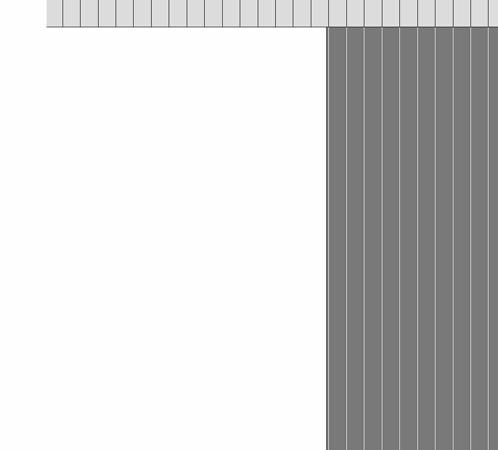
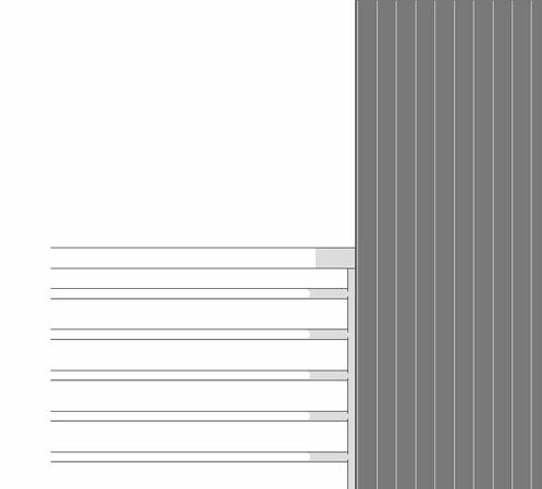
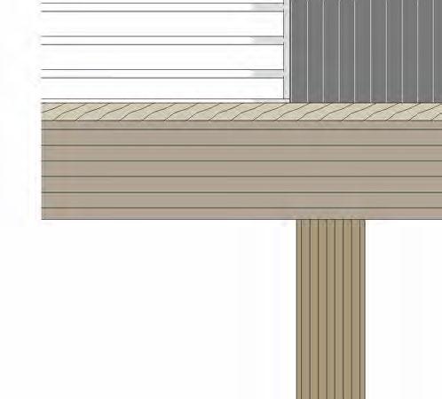
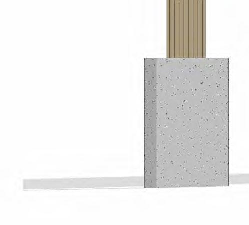


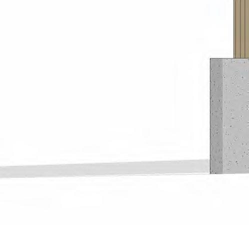
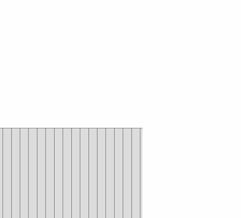
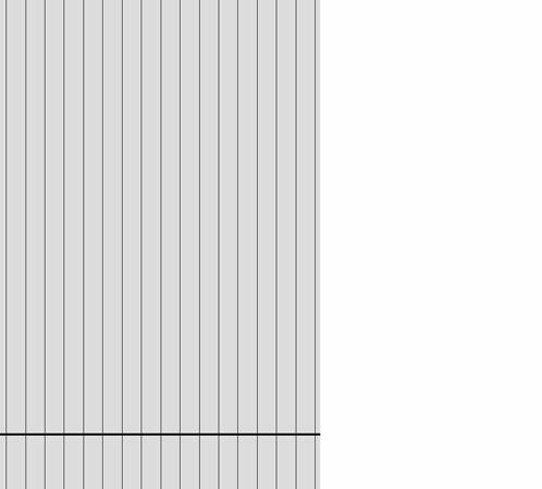
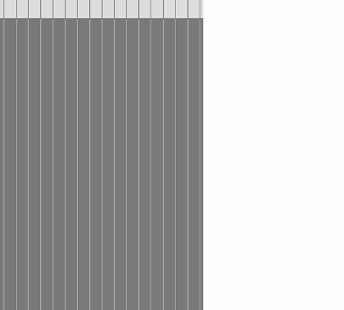

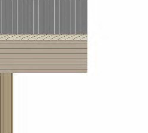
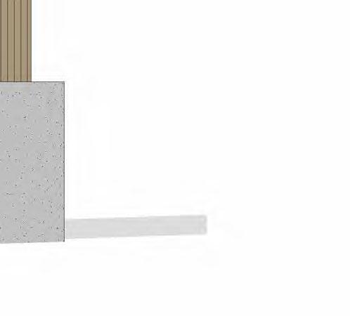
project 05 pg 44 story mill visitors center A Level 1 5' 0" Top of Structure Level 1 15' 0" Finished Ceiling 14' 0" Top of Window 12' 0" Level 0 -0 0' - 0" Level 1 5' - 0" 7 6 Top of Roof Level 1 19' - 8" Ground Level 0' - 0" Finished Ceiling 14' - 0" Top of Window 12' - 0" Scale DATE DRAWN BY 3/4" = 1'-0" 1 Wall Section Window - Callout 1 3/4" = 1'-0" 2 South Section Elevation 2 1. 1/2" Corrugated Aluminium Roof Panel 2. Air Weather Barrier 3. 2" Rigid Insulation 4. 3/4" Plywood Sheathing 5. 2"x8" Double Wood Header 6. 6" Batt Insulation 7. Wood Trusses 24" O.C. 8. Pressure Treated Plywood Soffit 9. 3/8" Gypsum Board 10. Vapor Barrier 11. 2"x6" Wood Studs 16" O.C. 12. 1 3/4" Rigid Insulation 13. 1" Air Space 14. Steel Z Clips 15. Corrugated Aluminium Panel Facade 16. 2"x8"Blocking 17. Steel Flashing 18. Wood Extension Jamb 19. Double Pane Glass 20. Window Sill 21. Wood Window Frame 22. Wood Sill Extension 23. 2"x8" Footer 24. 2"x8" Wood Floor Joist 25. Wood Slat Ceiling Panel 26. 2"x4" Wood Blocking 27. 7" Batt Insulation 28. 2"x12" Glulam Beam 29. 1.5" Plywood Subfloor 30. Slate Tile Finished Floor 31. Pressure Treated Plywood Deck Finish 32. 8"x8" Glulam Post 33. 18" Diameter Concrete Pier 34. Ceiling cable and steel bracket mount 1 2 3 4 5 6 7 8 9 10 11 12 13 14 15 16 17 18 19 20 21 22 23 16 26 27 28 29 30 32 33 31 3 4 24 25 34 17 May 3/4" Wall Library 1 15 28 Double pane wood framed window Wood Railing 32 33 Wood Decking No.DescriptionDate Client: Eric 1 2 wall section and elevation
pg 45 project 05 story mill visitors center Level 2 18' - 0" Level 1 5' - 0" 10 9 8 7 6 5 4 3 2 A5.1 1 A5.2 1 Top of Structure Level 2 27' - 0" Top of Roof Lvl 2 31' - 8" Ground Level 0' - 0" Library 3 Mech 4 Bathroom 5 Bathroom 6 Lobby 1 Reading Room 14 Finished Ceiling 14' - 0" Finished Ceiling Second Floor 26' - 0" B A C Level 1 5' - 0" D A5.4 1 A5.3 2 Top of Roof Level 1 19' - 8" Ground Level 0' - 0" Library 3 Assembly Hall 9 Finished Ceiling 14' - 0" Top of Window 12' - 0" 1/4" = 1'-0" 1 Tim Building Section 1 1/4" = 1'-0" 2 Section 13 Structural Wood Truss Aluminium Corrugated Roof Panel Exterior Wall (wood framed with aluminium corrugated wall panels) Wood framed double pane window Concrete pier foundation Glulam post Insulated floor assembly (wood framed with slate tile finish) Wood decking Wood floor joists Structural Wood Truss Aluminium Corrugated Roof Panel Exterior Wall (wood framed with aluminium corrugated wall panels) Concrete pier foundation Glulam post Insulated floor assembly (wood framed with slate tile finish) Wood decking Wood floor joists section one section two 10 9 8 7 6 5 4 3 2 A5.1 1 A5.2 1 Library 3 Mech 4 Bathroom 5 Bathroom 6 Lobby 1 Reading Room 14 B A C Level 1 5' - 0" D A5.4 1 A5.3 2 Top of Roof Level 1 19' - 8" Ground Level 0' - 0" Library 3 Assembly Hall 9 Finished Ceiling 14' - 0" Top of Window 12' - 0" Scale DATE DRAWN BY Story Mill Section 1 Tim Ottey, Anna Johnson May 12th, 2023 1/4" = 1'0" Building Sections A4.1 1/4" = 1'-0" 2 Section 13 Structural Wood Truss Aluminium Corrugated Roof Panel Exterior Wall (wood framed with aluminium corrugated wall panels) Wood framed double pane window Concrete pier foundation Glulam post Insulated floor assembly (wood framed with slate tile finish) Wood decking Wood floor joists Structural Wood Truss Aluminium Corrugated Roof Panel Exterior Wall (wood framed with aluminium corrugated wall panels) Concrete pier foundation Glulam post Insulated floor assembly (wood framed with slate tile finish) Wood decking Wood floor joists No.DescriptionDate 1 Adjust drawing scale 5/5 2 Add material notes 5/5 Client: Eric Watson
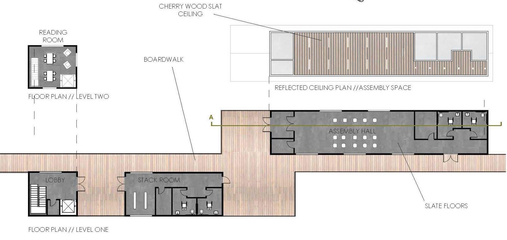
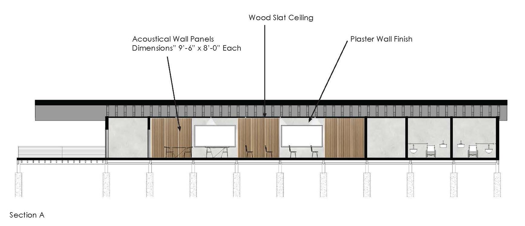
ACOUSTIC AND LIGHTING DESIGN
We completed both acoustic and lighting design for one room in the building. In order to appropriate STC ratings and acoustic character in the assembly hall, we utilized a wood panel system on the ceiling and portions of the wall. We also integrated our lighting system into the acoustic ceiling panels. This allowed us to achieve a cohesive aesthetic in the assembly hall. Through our selection of materials and products achieved appropriate acoustic and lighting levels for the assembly hall.
pg 46 project 05 story mill visitors center
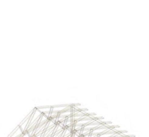
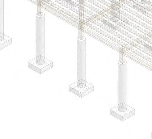
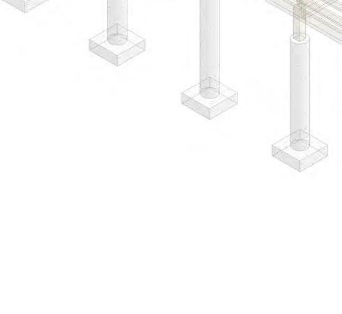
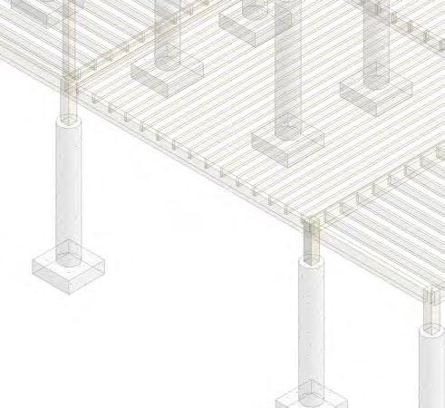
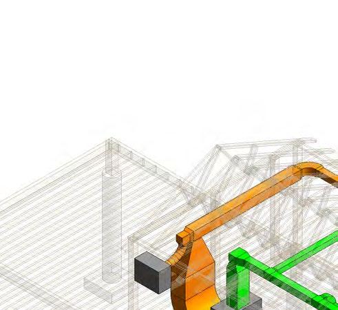
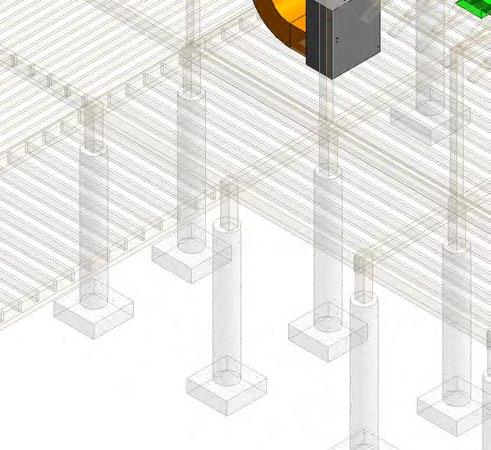
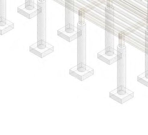
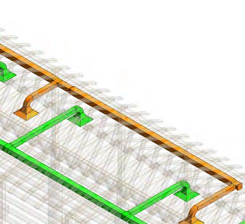
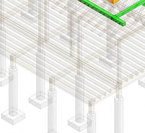
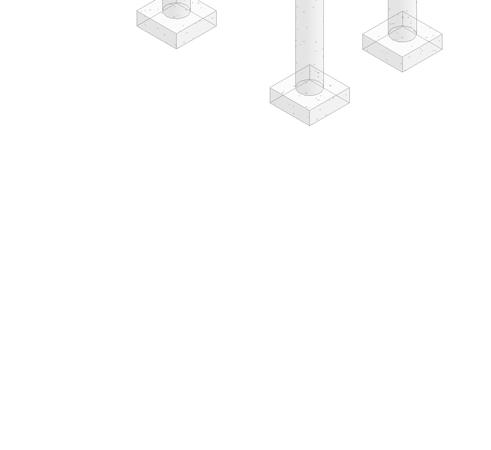
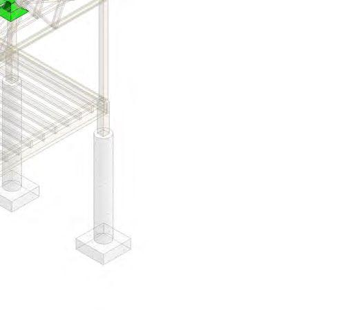
BUILDING SYSTEMS
These buildings axonometric drawings demonstrate the structural, mechanical, and electrical systems we designed for the building.
structural system
project 05 pg 49 story mill visitors center 6" Diameter Concrete Pier 3' x 3' x 1' Concrete Footing 1/2" Plywood Structural Panel for Shear 8" x 8" Glulam Post *Note: Stick frame construction Columns placed on all 10'0" O.C 2 (2" x 12") Perimeter Glulam 2" x 8" Wood Joists 16" 2" x 6" Wood Bottom (on all levels 1 and 2) 4X12 Glulam Beams to Support Roof Extension Scale DATE DRAWN BY 6" Diameter Concrete Pier x 3' x 1' Concrete Footing 0' 5' 10' 20' 40' No.DescriptionDate 1/2" Plywood Structural Panel for Shear 8" x 8" Glulam Post 6' X 6' Glulam Columns *Note: Stick frame construction between columns Columns placed on all corners, around openings, and/or 10'0" O.C Simple Fink Truss 24" O.C. 2" x 6" Wood Top Plate (on all levels 1 and 2) 2" x 12" Perimeter Glulam Beam 2 (2" x 12") Perimeter Glulam Beams 2" x 8" Wood Joists 16" O.C. 2" x 6" Wood Bottom Plate (on all levels 1 and 2) 4X12 Glulam Beams to Support Roof Extension Client: Eric 6" Diameter Concrete Pier 3' x 3' x 1' Concrete Footing 1/2" Plywood Structural Panel for Shear 8" x 8" Glulam Post *Note: Stick frame construction Columns placed on all corners, around 10'0" O.C 2 (2" x 12") Perimeter Glulam Beams 2" x 8" Wood Joists 16" O.C. 2" x 6" Wood Bottom Plate (on all levels 1 and 2) 4X12 Glulam Beams to Support Roof Extension DATE DRAWN 6" Diameter Concrete Pier 3' x 3' x 1' Concrete Footing 1/2" Plywood Structural Panel for Shear 8" x 8" Glulam Post 6' X 6' Glulam Columns *Note: Stick frame construction between columns Columns placed on all corners, around openings, and/or 10'0" O.C Simple Fink Truss 24" O.C. 2" x 6" Wood Top Plate (on all levels 1 and 2) 2" x 12" Perimeter Glulam Beam 2 (2" x 12") Perimeter Glulam Beams 2" x 8" Wood Joists 16" O.C. 2" x 6" Wood Bottom Plate (on all levels 1 and 2) 4X12 Glulam Beams to Support Roof Extension Client:


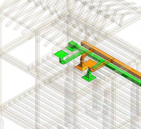
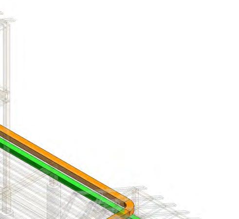
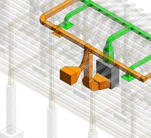
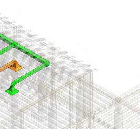


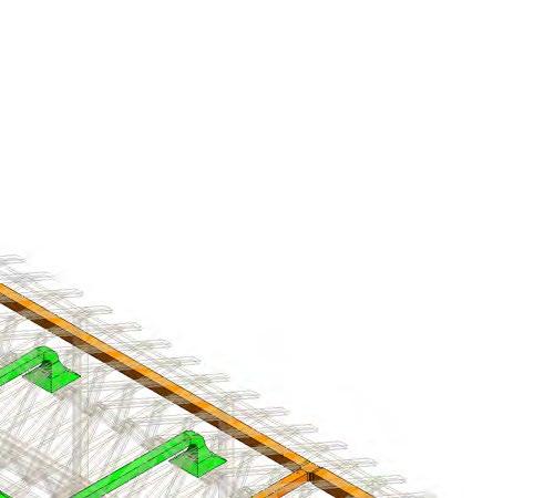
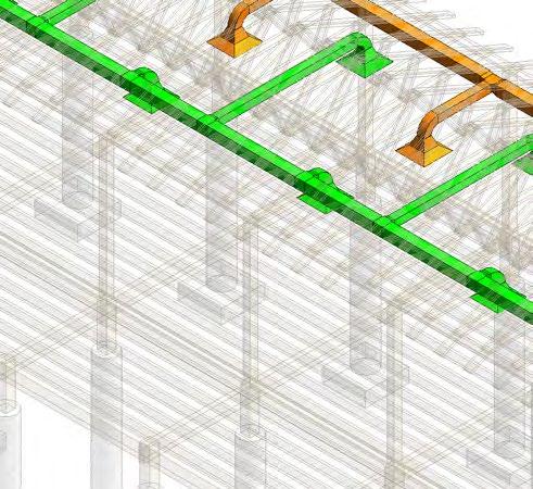

project 05 pg 50 story mill visitors center Scale DATE DRAWN BY Story Mill Tim Ottey, May 12th, M2.2 Mechanical No.DescriptionDate 1/8" -1'-0" Client: Eric Watson Scale DATE DRAWN BY Story Mill Tim 03.30.2023 A113 Mechanical No.DescriptionDate 1 MECHANICAL AXON Return Air Supply Air Outside Make-up Air Air Handling Unit Air Handling Unit Outside Make-up Air 1/8" -1'-0" Air supplied to LVL. 2 through floor Scale DATE DRAWN BY Story Mill E1.1 Electrical Tim Ottey, Anna Johnson May 12th, 2023 1/8" = No.DescriptionDate Client: Eric Watson D D 2 3 3 Scale DATE DRAWN BY Story Mill 1 Electrical Lighting A110 Electrical Tim Ottey, Anna 03.30.2023 As Indicated No.DescriptionDate Transformer Electric Panelboard Electric Panelboard Transformer Box Electrical Panelboard Electrical Panelboard electrical/lighting system mechanical system
THANK YOU.